Assembly Instructions for 128x64 Graphics Display Unit
|
|
|
- Donna Porter
- 6 years ago
- Views:
Transcription
 to be used in conjunction with the 16 Bit Micro Experimenter on a solderless breadboard.")

1 02/15/10 version 1.0 Assembly Instructions for 128x64 Graphics Display Unit This document describes the physical assembly of the Graphic Display unit for the 16 Bit Experimenter 128x64 Graphics kit. It was created by KibaCorp ( ) to be used in conjunction with the 16 Bit Micro Experimenter on a solderless breadboard. The graphics display unit consists of a LCD backlight modules and total assembly should take under 15 minutes, however, special attention needs to be given to the removal of protective covers and films on both the LCD display and backlight and then their final assembly. A soldering iron will be required. Kits Contents The kits should contain the following: 1. (1) EADOGM128W-6 LCD Display package 2. (1) EALED55X46-W LCD Backlight package 3. (9) 1 uf ceramic capacitors ( marked 105) 4. (3) 100 ohm ¼ watt resistors 5. CD-ROM with Assembly Instructions, Code See attached figure (CD-ROM Not shown) Figure 1 Kit Contents

2 Graphics Module Assembly Remove the Backlight and LCD module from their perspective packages. Line them up side by side and you should get something like is shown in figure below. Both modules contain protective films that will need to be removed before final assembly. The final assembly will consist of the LCD display mounted on top of the Backlight module and then soldered together. Let s start with the Back Light module first. 1. Backlight -Step 1 Remove plastic cover from top of back light module. As shown. 2. Backlight Step 2 Remove the next layer of covering material from front of backlight it is marked with white tape around the edges.


3 What you should be left with it is a final covering for light dispersion with black tape on top and bottom. Leave this covering you are done with the back light for now. 3. LCD Step 1 Let s now work the LCD module. Let s remove the front cover plastic protective film as shown.


4 4. LCD Step 2 We are done with the front of the LCD, let flip it on it back as shown. 4. LCD Step 3 Remove the protective plastic cover from the back of the display as shown. Ok we are now done with the LCD display.


5 5. Final Assembly the of Graphics Kit You should now have the units completely remove of all protective covers and lined up side by side as shown Take the LCD unit and place it on top the backlight. The Pins of the LCD should align with the corresponding holes in the backlight. The assembly should now look like what shown here. We are not done. The units need to be soldered together. Before doing so make sure both units are flush with each other. This is important for two reasons 1. Maximum light transfer from backlight to LCD 2. Maximum extension of pins from bottom to enable plug-in to solderless breadboard as a complete unit. Turn the unit up side down, again make sure the two modules are flush,-- and Apply solder to bottom pins. Congratulations- your graphics Unit is complete!
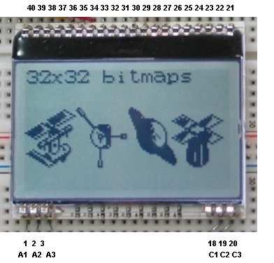
6 6. Integration and test You now need to integrate with your 16 Bit Micro experimenter. First turn off the Experimenter, and then plug in the Graphics Module as shown. You need to supply a large format solderless breadboard and hook up wires. The kit supplied capacitors and resistors are used to complete the circuit. Complete the circuit using the hook up diagram. You will need to supply +3.3VDC and ground to the unit. Power is readily available from the 16 Bit Experimenter. Once done you can turn on the Experimenter. The graphics unit should be backlit. The Demo application code for this project is downloadable from the Nuts and Volts website or and it also included in the kit CD- ROM. Make sure to install all Microchip tools ( MPLAB, P24F C Compiler, and PICKIT2) before hand. Please download, unzip, and place the project folder GRPAHICSDEMO on your desktop and put these in a convenient location on your computer. Now connect the PICKIT2 to USB of you computer and the other end to the ICSP on the Experimenter. Switch on power to the Experimenter. Open the folder containing our application code, and double click project file SDMMCTest.mcp. You should see the MPLAB GUI with the demo project directory visible, C code for Main function is open, and the output window should display PICKIT2 ready, PIC24FJ64GA002 found, and show that target power is applied. We are almost there. On the IDE toolbar click the Build button, and watch IDE and PIC 24 C Compiler compile the program. The output window should indicate no compile error. Use Program option pull down list and select program. The PICKIT2 will then actively program the PIC24F flash on your breadboard through ICSP. At the completion of this your Experimenter ought to automatically come up with Graphics Application. You can now either remove the PICKIT2 from the ICSP or leave it connected. The Experimenter will now work independently on each power up cycle. The demo should exercise the graphics unit with all the features of the KibaCorp graphics Library automatically enjoy! Figure 1 shows an example of the graphics kit in use with the Experimenter running the GRAPHICSDEMO software. Figure shows hook up of

7 The pin out orientation and hook up diagram for graphics Module is shown below.
8
9 KibaCorp believes in total customer support. Your success and satisfaction is also ours. Please feel free to drop us a line or discuss any issues you may have in using this product or the EXP-16 at kibacorpinc@gmail.com.
04/12/11 version 1.0
 04/12/11 version 1.0 Assembly Manual and Hardware Description for the Universal Graphics Display Module Kit This document describes the physical assembly and operation of the new KibaCorp Universal Graphic
Product Overview -A 16 bit Micro Experimenter for Solderless Breadboards
 Product Overview -A 16 bit Micro Experimenter for Solderless Breadboards 1.0 Introduction The 16 Bit Micro Experimenter is an innovative solderless breadboard kit solution developed by a Microchip Academic
32 bit Micro Experimenter Board Description and Assembly manual
 32 bit Micro Experimenter Board Description and Assembly manual Thank you for purchasing the KibaCorp 32 bit Micro Experimenter. KibaCorp is dedicated to Microcontroller education for the student, hobbyist
Introducing the 32 bit Micro Experimenter
 Introducing the 32 bit Micro Experimenter In a 2010, Nuts and Volts introduced the 16 bit Micro Experimenter with a seven article series. The 16 bit Experimenter offered the readership a new and significant
PIC KIT 2 BASIC-USERS GUIDE FEMTO ELECTRONICS
 PIC KIT 2 BASIC-USERS GUIDE FEMTO ELECTRONICS SPECIFICATIONS: ICSP (In Circuit Serial Programmer). Compatible with PIC Microcontrollers (5V chips only). Compatible with MPLAB, MPLAB X and PIC KIT 2 software.
PIC 28 Pin Board Documentation. Update Version 5.0
 PIC 28 Pin Board Documentation Update 2009.10 Version 5.0 Table of Contents PIC 28 Pin Board Documentation... 1 Table of Contents... 2 Introduction... 3 Circuit Schematic... 4 The following is the Circuit
Assembly Instructions (8/14/2014) Your kit should contain the following items. If you find a part missing, please contact NeoLoch for a replacement.
 Your kit should contain the following items. If you find a part missing, please contact NeoLoch for a replacement.") NeoLoch NLT-28P-LCD-5S Assembly Instructions (8/14/2014) Your kit should contain the following items. If you find a part missing, please contact NeoLoch for a replacement. Kit contents: 1 Printed circuit
NeoLoch NLT-28P-LCD-5S Assembly Instructions (8/14/2014) Your kit should contain the following items. If you find a part missing, please contact NeoLoch for a replacement. Kit contents: 1 Printed circuit
EE 354 August 1, 2017 Assembly of the AT89C51CC03 board
 EE 354 August 1, 2017 Assembly of the AT89C51CC03 board The AT89C51CC03 board comes as a kit which you must put together. The kit has the following parts: No. ID Description 1 1.5" x 3.25" printed circuit
AXE Stack 18. BASIC-Programmable Microcontroller Kit. An inexpensive introduction to microcontroller technology for all ability levels
 Ltd AXE Stack 18 BASIC-Programmable Microcontroller Kit a division of An inexpensive introduction to microcontroller technology for all ability levels Free Windows interface software Programmable in BASIC
Part 2: Building the Controller Board
 v3.01, June 2018 1 Part 2: Building the Controller Board Congratulations for making it this far! The controller board uses smaller components than the wing boards, which believe it or not, means that everything
Images Scientific OWI Robotic Arm Interface Kit (PC serial) Article
 Article") Images Scientific OWI Robotic Arm Interface Kit (PC serial) Article Images Company Robotic Arm PC Interface allows real time computer control and an interactive script writer/player for programming and
Images Scientific OWI Robotic Arm Interface Kit (PC serial) Article Images Company Robotic Arm PC Interface allows real time computer control and an interactive script writer/player for programming and
Building RoboPIC 18F4550
 RoboPIC 8F4550 Copyright 206 William Henning Building RoboPIC 8F4550 Copyright 206 William Henning RoboPIC 8F4550 build manual v0.90 The most up to date documentation will always be available at: http://www.mikronauts.com/robot-controllers/robopic-8f4550/
LED Knight Rider. Yanbu College of Applied Technology. Project Description
 LED Knight Rider Yanbu College of Applied Technology Project Description This simple circuit functions as a 12 LED chaser. A single illuminated LED 'walks' left and right in a repeating sequence, similar
Pacific Antenna Two Tone Generator
 Pacific Antenna Two Tone Generator Description Our Two Tone Generator kit provides two non-harmonic, sine wave signals for testing audio circuits Outputs of approximately 700Hz and 1900Hz and the combination
Dwarf Boards. DB057 : 40-pin controller board
 Dwarf Boards DB057 : 40-pin controller board PICmicro, In-Circuit Serial Programming and ICSP are registered trademarks of Microchip Technology Inc. DB057 for USB PIC DB057 for non-usb PIC Introduction
Sierra Radio Systems. HamStack. Project Board Reference Manual V1.0
 Sierra Radio Systems HamStack Project Board Reference Manual V1.0 Welcome HamStack Project Board Reference Manual Revision 1.0.3 2011 George Zafiropoulos, KJ6VU and John Best, KJ6K This guide provides
Rapid40i PIC Prototyping PCB User Manual
 Description This is a PCB designed to facilitate the rapid prototyping of a device based on a 40 pin Microchip PIC microcontroller. To allow users to focus on their application, we take care of key housekeeping
Assembly Guide. LEDs. With these assembly instructions, you can easily build your own SWT16. All required components are included in this kit.
 Assembly Guide With these assembly instructions, you can easily build your own SWT16. All required components are included in this kit. You need the following tools: soldering iron, wire cutter and solder.
Sierra Radio Systems. Making a Keyer with the. HamStack. Project Platform
 Sierra Radio Systems Making a Keyer with the HamStack Project Platform Introduction The HamStack Project Board includes primary interface elements needed to make a high quality CW keyer. Using the LCD
PIC Dev 14 Surface Mount PCB Assembly and Test Lab 1
 Name Lab Day Lab Time PIC Dev 14 Surface Mount PCB Assembly and Test Lab 1 Introduction: The Pic Dev 14 SMD is a simple 8-bit Microchip Pic microcontroller breakout board for learning and experimenting
Bill of Materials: Turn Off the Lights Reminder PART NO
 Turn Off the Lights Reminder PART NO. 2209650 Have you ever woke up early in the morning to find out that the kids (or adults) in your home forgot to turn off the lights? I've had that happen a number
TDSDB Features. Description
 TDSDB14550 Features Inexpensive development or project board providing quick start up solution. 5v Pic alternative to the 3.3v TDSDB146J50 Mini B USB socket to provide power and USB functionality. 40 pin
Morse Code Practice Oscillator
 Features Description Keyer speed range: Limited only by keying source True Sine wave tone output Tone Volume Control Tone Frequency Control Internal Speaker 1/8 External Speaker/Headphone Jack RCA Key
Bill of Materials: 8x8 LED Matrix Driver Game PART NO
 8x8 LED Matrix Driver Game PART NO. 2171031 This Game Maker II kit is a game design platform using a single color 8x8 matrix LED without the need for a shift register or expensive Arduino. The kit includes
Thank you for purchasing the RGB Multi-MCU base and driver board from SuperTech-IT and TheLEDCube.com
 CONGRATULATIONS Thank you for purchasing the RGB Multi-MCU base and driver board from SuperTech-IT and TheLEDCube.com In this document, MCU means Microcontroller such as the PIC32, ATmega328P, prototype
COS 116 The Computational Universe Laboratory 7: Digital Logic I
 COS 116 The Computational Universe Laboratory 7: Digital Logic I In this lab you ll construct simple combinational circuits in software, using a simulator, and also in hardware, with a breadboard and silicon
PIC Dev 14 Through hole PCB Assembly and Test Lab 1
 Name Lab Day Lab Time PIC Dev 14 Through hole PCB Assembly and Test Lab 1 Introduction: The Pic Dev 14 is a simple 8-bit Microchip Pic microcontroller breakout board for learning and experimenting with
Dwarf Boards. DN001 : introduction, overview and reference
 Dwarf Boards DN001 : introduction, overview and reference (c) Van Ooijen Technische Informatica version 1.6 PICmicro, In-Circuit Serial Prograing and ICSP are registerd trademarks of Microchip Technology
Post Tenebras Lab. Written By: Post Tenebras Lab
 Post Tenebras Lab PTL-ino is an Arduino comptaible board, made entirely out of through-hole components. It is a perfect project to learn how to solder and start getting into the world of micro controllers.
LCD Prototype Circuit on Solderless Breadboard. 840 Pin Solderless Breadboard (http://www.digikey.com/ # ND)
") Solderless Breadboard Tutorial Cornerstone Electronics Technology and Robotics I Week 3 Solderless Breadboards: o Solderless breadboards are commonly used in experimentation or to make a prototype of a
Solderless Breadboard Tutorial Cornerstone Electronics Technology and Robotics I Week 3 Solderless Breadboards: o Solderless breadboards are commonly used in experimentation or to make a prototype of a
4.1 Parts and Components... IV Assembly Tips... IV Assembly Precautions... IV Required Tools, Equipment and Materials..
 IV PERSONALITY MODULE ASSEMBLY 4.1 Parts and Components............ IV-1 4.2 Assembly Tips............... IV-1 4.3 Assembly Precautions............ IV-1 4.4 Required Tools, Equipment and Materials.. IV-1
Rapid28iXL PIC Prototyping PCB User Manual
 Description Features This is a PCB designed to facilitate the rapid prototyping of a device based on a 28 pin Microchip PIC microcontroller. To allow users to focus on their application, we take care of
Chill Interface PCB Assembly Instructions
 ExcelValley Chill Interface PCB Waveblaster Module MIDI Interface Board Chill Limited Edition V2 Assembly Kit Standalone midi interface board for Waveblaster synthesizer modules. Suitable for most Waveblaster
Rapid40iXL PIC Prototyping PCB User Manual
 Description This is a PCB designed to facilitate the rapid prototyping of a device based on a 40 pin Microchip PIC microcontroller. To allow users to focus on their application, we take care of key housekeeping
ARRL ETP Solder Hour Clock Kit Construction Manual
 ARRL ETP Solder 101 24-Hour Clock Kit Construction Manual Do a complete parts check cross checking the individual parts against the parts list. Pay particular attention to the color code for the resistors:
Transcendent Frequency Counter
 Transcendent Frequency Counter with blue 2 x 16 LCD display This manual will guide you how to assemble, test and operate this frequency counter KIT. Features: The transcendent counter has two input channels
Button Code Kit. Assembly Instructions and User Guide. Single Button Code Entry System
 Button Code Kit Single Button Code Entry System Assembly Instructions and User Guide Rev 1.0 December 2009 www.alan-parekh.com Copyright 2009 Alan Electronic Projects Inc. 1. Introduction... 4 1.1 Concept
APP-II PIC Development Kit by AWC
 APP-II PIC Development Kit 2001-2003 by AWC AWC 1279 FM 518 #2 Kemah, TX 77565 (281) 334-4341 http://www.awce.com V1.3 7 Sep 2004 Table of Contents Overview...1 If You Need Help...1 What Else You'll Need...1
RFID: Read and Display V2010. Version 1.1. Sept Cytron Technologies Sdn. Bhd.
 PR8-B RFID: Read and Display V2010 Version 1.1 Sept 2010 Cytron Technologies Sdn. Bhd. Information contained in this publication regarding device applications and the like is intended through suggestion
UF-3701 Power Board Construction Guide
 Page 1/5 Soldering and Part Placement See the Chapter 3 of the MIT 6270 Manual for information on electronic assembly, including soldering techniques and component mounting. Construction Information All
Build the Machine Science XBoard, with a programmable microcontroller.
 Build the Machine Science XBoard, with a programmable microcontroller. Site: icode Course: Machine Science Guides Book: Assembling the XBoard Printed by: Guest User Date: Monday, May 24, 2010, 10:46 AM
K8099 NIXIE CLOCK. * optional enclosure TKOK19 (black) - TKOK17 (white) ** optional plexiglass enlcosure B8099 ILLUSTRATED ASSEMBLY MANUAL
 - TKOK17 (white) ** optional plexiglass enlcosure B8099 ILLUSTRATED ASSEMBLY MANUAL") Total solder points: 230 + 74 Difficulty level: beginner 1 2 3 4 5 advanced NIXIE CLOCK K8099 ** * A unique combination of both vintage and modern electronics ILLUSTRATED ASSEMBLY MANUAL H8099IP-1 * optional
Total solder points: 230 + 74 Difficulty level: beginner 1 2 3 4 5 advanced NIXIE CLOCK K8099 ** * A unique combination of both vintage and modern electronics ILLUSTRATED ASSEMBLY MANUAL H8099IP-1 * optional
Storage Card Interface Kit
 Storage Card Interface Kit for MultiMediaCards(MMC) and Secure Digital Cards (SD) MMSD3K The MMSD3K is complete development kit interfaced to a SD or MMC card. This board ideal for projects that involve
PICado Alpha Development Board V1.0
 V1.0 Bluetooth Transceiver Module HC-05 Four onboard FET power output stage 34 freely assignable I/O pins ICSP interface 2015 Jan Ritschard, All rights reserved. V1.0 Table of Contents 1. Introduction...
Pacific Antenna Easy TR Switch Kit
 Pacific Antenna Easy TR Switch Kit Kit Description The Easy TR Switch is an RF sensing circuit with a double pole double throw relay that can be used to automatically switch an antenna between a separate
PROTO BOARD SETUP Here is a schematic of the circuit we will build.
 PROTO BOARD SETUP Here is a schematic of the circuit we will build. Cut off the connector from the end of your 5V supply and strip the insulation off for one half inch. Tin the striped ends with solder.
Getting acquainted with the development tools June 27, 2006 ELE492 Embedded System Design Exercise 1
 Getting acquainted with the development tools June 27, 2006 ELE492 Embedded System Design Exercise 1 Overview In this first exercise, a few tasks are given to get acquainted with the PIC microcontroller
Bill of Materials: Picaxe-based IR Control Module Pair PART NO
 Picaxe-based IR Control Module Pair PART NO. 2171014 The IRGEII is an IR (Infra Red) Transmitter and Receiver pair that uses a 38 KHZ frequency of invisible light to communicate simple instructions. The
Schematic Diagram: R2,R3,R4,R7 are ¼ Watt; R5,R6 are 220 Ohm ½ Watt (or two 470 Ohm ¼ Watt in parallel)
") Nano DDS VFO Rev_2 Assembly Manual Farrukh Zia, K2ZIA, 2016_0130 Featured in ARRL QST March 2016 Issue Nano DDS VFO is a modification of the original VFO design in Arduino Projects for Amateur Radio by
Nano DDS VFO Rev_2 Assembly Manual Farrukh Zia, K2ZIA, 2016_0130 Featured in ARRL QST March 2016 Issue Nano DDS VFO is a modification of the original VFO design in Arduino Projects for Amateur Radio by
CYTRON USB PIC Programmer v2009 UP00B
 CYTRON USB PIC Programmer v2009 UP00B User s Manual V1.0 Nov 2008 Information contained in this publication regarding device applications and the like is intended through suggestion only and may be superseded
HAND HELD PROGRAMMER QUICK START GUIDE
 HAND HELD PROGRAMMER QUICK START GUIDE IMPORTANT INFORMATION 1) Do not leave the programmer connected to the PC adapter or a target system, as this will drain the battery. Installing Software 1) Run the
Microsystems. SCI-6 Sound Card Interface Kit Version 1.09 January 2015
 UM Unified Microsystems SCI-6 Sound Card Interface Kit Version 1.09 January 2015 The SCI-6 interface was designed to be a low cost, high quality interface between your PC s sound card and radio transceiver.
LocoBuffer Documentation 08/07/2003
 LocoBuffer Documentation 08/07/2003 Subjects Disclaimer Overview Hardware Software Revision History PIC Programming Debugging Tips Printed Circuit Board ICSP (In Circuit Serial Programming) Assembly instructions
Bill of Materials: Handheld Game System PART NO
 Handheld Game System PART NO. 2245108 Build your own Handheld Game System with graphics and sound! This game kit includes a custom designed circuit board along with custom built tools and programming to
BuffaloLabs WiFi Lantern Assembly guide version 1
 BuffaloLabs WiFi Lantern Assembly guide version 1 Needed equipment: Solder iron Solder wire Cutter Wire stripper (optional) Hot glue gun Overview of the components (not including USB cable and box panels)
REMOTE HEAD ADAPTER INSTALLATION GUIDE
 REMOTE HEAD ADAPTER INSTALLATION GUIDE The Remote Head adapter is a valuable accessory for the Uniden BC-780, 785 and 796 scanners. It allows the scanner's control panel to be removed from the radio and
SK40C ENHANCED 40 PINS PIC START-UP KIT. User s Manual V1.3. March 2012
 SK40C ENHANCED 40 PINS PIC START-UP KIT User s Manual V1.3 March 2012 Information contained in this publication regarding device applications and the like is intended through suggestion only and may be
A Backlighted LCD for your K1
 A Backlighted LCD for your K1 (K1BKLTKIT) Tom Hammond - NØSS, July 27, 2006 Rev C Thanks to Wayne Burdick, N6KR for suggesting this implementation of backlighting the K1 display. APPLICABILITY This modification
Installing LE History Record Reader program software.
 INSTALLATION & OPERATING INSTRUCTIONS FOR THE LE HISTORY RECORD READER These Instructions will inform you on how to install software to use the RS-232/USB Isolator- Adapter and your LE History Record Reader
K1EL Morse Code Practice Oscillator CPO
 Features This is an oscillator not a Morse keyer Input source can be a keyer or straight key Near Sine wave tone output CPO Tone Volume Control CPO Tone Frequency Control Use headphones or external speaker
Good Idea to Working Electronic Model
 Good Idea to Working Electronic Model by Jan H. Lichtenbelt, March 2011 Abstract Seeing an idea manifest itself into a fully working creation is always satisfying, however so many good ideas go to waste
Digital Candle 1.0 Kit
 Kit Instruction Manual Eastern Voltage Research, LLC June 2012, Rev 1 1 http://www.easternvoltageresearch.com Introduction to the Kit Thank you for purchasing the Kit. This kit is definitely a favorite
GLiPIC Ver C Assembly manual Ver 1.0
 GLiPIC Ver C Assembly manual Ver 1.0 Last Rev 1.1 Oct 30, 2001 Author: Ranjit Diol Disclaimer and Terms of Agreement As with any kit, only the individual parts supplied are guaranteed against defects and
Specification. 1.Power Supply direct from Microcontroller Board. 2.The circuit can be used with Microcontroller Board such as Arduino UNO R3.
 Part Number : Product Name : FK-FA1410 12-LED AND 3-BOTTON SHIELD This is the experimental board for receiving and transmitting data from the port of microcontroller. The function of FK-FA1401 is fundamental
Description: USB to Serial interface and USB development platform
 Device: PLT-1003 This document Version: 1.0 Date: October 2010 Description: USB to Serial interface and USB development platform PLT-1003 datasheet Page 2 Table of Contents Introduction... 3 Features...
Connecting LEDs to the ADB I/O
 Application Note AN-2 By Magnus Pettersson September 26 1996 Connecting LEDs to the I/O Introduction The following notes are for those of you who are a bit inexperienced with hardware components. This
RS-232 Driver Module
 RS-232 Driver Module Low Cost TTL to RS-232 Adapter DCE (SKU #30000) DTE (SKU #30010) Transmit and receive RS-232 Data Can be mounted on any solderless breadboard, or hard-wired Reconfigurable for DCE
C S Technology Ltd. cstech.co.uk. DTMF display 32 kit with 2 line x 16 LCD display
 C S Technology Ltd cstech.co.uk DTMF display 32 kit with 2 line x 16 LCD display Our DTMF display can display up to 32 characters (16 per line). The display can be cleared by a button (not supplied) or
KNIGHT S GALLOP ALGO-RHYTHMIC GENERATOR BUILDING GUIDE
 KNIGHT S GLLOP LGO-RHYTHMIC GENERTOR UILDING GUIDE Table of Contents 01. Components List + Tools 02. PC Sides 03. Important Note 04. Top PC ssembly 04_1. Diode 1N4148 04_2. Laying Resistors 04_3. Zenner
Figure 3.0, Schematic for display application
 Including lighting for model railroad water towers, bridge, runway, running and crossing lights, rolling hardware and storefront dress-up lights are now easy then ever. While there are several kits readily
The PUMPKIN LIGHT LED
 The PUMPKIN LIGHT LED PUMPKIN LIGHT LED By Mark McCuller Email: mcculler@mail.com DESIGN SUMMARY The PUMPKIN LIGHT LED By: Mark McCuller The Pumpkin Light LED is a battery-powered device that illuminates
Manual Version March 2007
 Manual Version 1.1 - March 2007 Page 1 Table of Contents Section1: 6922 Line Board Build... 3 6922 Line Board Version Notes... 5 6922 Line Board Build - HARD-WIRED VERSION... 5 Final Connections and Checks
Building Morpheus v1.00a
 Building Morpheus v1.00a Version 0.95 Copyright 2009 by William Henning Updated documentation will always be available at Morpheus v0.1 in mid-2008 1 Table of Contents Introduction...4 Top of board:...4
Cumbria Designs T-1. C-1 Controller. User Manual
 Cumbria Designs T-1 C-1 Controller User Manual CONTENTS 1 INTRODUCTION 2 2 CIRCUIT DESCRIPTION 2 3 ASSEMBLY 3 4 CONNECTIONS AND CONFIGURATION 4 5 TESTING 6 Appendix A C-1 Circuit Diagram and PCB Component
USBCNC USB Disk Key reader for CNC Controls Machine Mount instructions
 USBCNC USB Disk Key reader for CNC Controls Machine Mount instructions 2008-2015 Calmotion LLC, All rights reserved Calmotion LLC 21720 Marilla St. Chatsworth, CA 91311 www.calmotion.com Introduction This
Drexel University Electrical and Computer Engineering Department ECE 200 Intelligent Systems Spring Lab 1. Pencilbox Logic Designer
 Lab 1. Pencilbox Logic Designer Introduction: In this lab, you will get acquainted with the Pencilbox Logic Designer. You will also use some of the basic hardware with which digital computers are constructed
Parts List: Part # Tools List: Instructions:
 Parts List: Part # 1 pair of Dayton Audio B652s 300-652 1 Dayton Audio DTA-2 amplifier 300-385 1 MP3 module 320-350 1 7805 +5 VDC voltage regulator 7805 1 12 VDC 2A power supply 129-077 1 2.1 mm panel
Electronic Coin Toss
 1 Electronic Coin Toss Why this circuit? This circuit was not designed for people who can make up their mind nor have a coin to use for a heads or tail coin toss. This circuit can also be used to ask it
Phi-panel backpack assembly and keypad options Dr. John Liu 12/16/2012
 Phi-panel backpack assembly and keypad options Dr. John Liu 12/16/2012 1. Introduction:... 3 Currently available:... 3 2. Backpack assembly... 4 3. Connecting to a keypad... 6 4. Rotary encoder keypads...
Carefully remove the translite from the backbox and then lower the speaker panel to the position shown in Fig. A to gain access to the backbox.
 Installation Instructions for Data East (wooden speaker panel) Congratulations on the purchase of your new display. The will enhance your pinball machine by introducing color to the dot matrix display
*on-board power supply capability limited. External battery should be used for higher power servos.
 Pan and Tilt Decoder II PART NO. Add affordable Pan and Tilt control to your security cameras using the Pan and Tilt Decoder II and the DFRobot DF05BB Tilt/Pan Kit (5kg), Jameco PN 2144518 or the DAGU
Using solderless breadboards
 Page 1 of 9 Using solderless breadboards This document describes how to use the solderless breadboards available in the experimental didactic lab (LED, previously LADISPE) of Politecnico di Torino. 1 Setting
Cygnos360 V2 Installation Manual
 VERSION 1.0. - OKTOBER, 2009 www.cygnos360.com Contents: 1. What you need...2 1.1. Tools...2 2. Preparation...3 2.1. Preparing the solder points...3 3. Installing in your Xbox360...4 3.1. Installing the
Wiring an LED Guide for BeagleBone (Black/Green) Table of Contents. by Brian Fraser Last update: November 16, Target Linux Kernel: 4.
 Table of Contents. by Brian Fraser Last update: November 16, Target Linux Kernel: 4.") Wiring an LED Guide for BeagleBone (Black/Green) by Brian Fraser Last update: November 16, 2017 Target Linux Kernel: 4.4 This document guides the user through: 1. Wiring an LED on P9.23 & controlling it
Wiring an LED Guide for BeagleBone (Black/Green) by Brian Fraser Last update: November 16, 2017 Target Linux Kernel: 4.4 This document guides the user through: 1. Wiring an LED on P9.23 & controlling it
K2 RIT-SPLIT LED Indicator Mod dated 18 October 2003 Circuit Design by: Wayne Burdick, N6KR Implementation by: Tom Hammond, NØSS
 K2 RIT-SPLIT LED Indicator Mod dated 18 October 2003 Circuit Design by: Wayne Burdick, N6KR Implementation by: Tom Hammond, NØSS Show & Tell Pictorial Supplement to the K2 RIT-SPLIT LED Mod Documentation
OpenSprinkler v2.1u Build Instructions
 OpenSprinkler v2.1u Build Instructions (Note: all images below are 'clickable', in order for you to see the full-resolution details. ) Part 0: Parts Check Part 1: Soldering Part 2: Testing Part 3: Enclosure
KPIC-0818P (V050919) Devices Included in this Data sheet: KPIC-0818P
 Devices Included in this Data sheet: KPIC-0818P") Devices Included in this Data sheet: KPIC-0818P Features: Carefully designed prototyping area Accepts 8 pin PIC12 series micro-controllers Accepts 14 and 18 Pin PIC16 series Accepts some 8,14 and 18 pin
Devices Included in this Data sheet: KPIC-0818P Features: Carefully designed prototyping area Accepts 8 pin PIC12 series micro-controllers Accepts 14 and 18 Pin PIC16 series Accepts some 8,14 and 18 pin
PIEXX UT36 px Installation Instructions
 PIEXX UT36 px Installation Instructions The PIEXX UT-36 px is a physical and electrical replacement for the original ICOM UT-36 speech synthesizer. UT-36 px Installation The UT-36 px speech synthesizer
3 pyro output datalogger altimeter with an ATmega 328 microcontroller Kit assembly instructions
 3 pyro output datalogger altimeter with an ATmega 328 microcontroller Kit assembly instructions Version date Author Comments 1.0 29/05/2013 Boris du Reau Initial version Rocket Type Micro-max Model Mid
Storage Card Interface Kit
 Storage Card Interface Kit for MultiMediaCards(MMC) and Secure Digital Cards (SD) MMSD3F The MMSD3K is complete development kit interfaced to a SD or MMC card. This board ideal for projects that involve
TIME WIZARD MULTI CLOCK DIVIDER BUILDING GUIDE
 TIME WIZARD MULTI CLOCK DIVIDER BUILDING GUIDE Table of Contents 0. Components List + Tools 0. PCB Sides 03. PCB Assembly 04_. Diode N448 04_. Laying Resistors 04_3. Capacitors 04_4. Quartz 04_5. 78L05
Carefully remove the translite from the backbox and then swing speaker panel to the open position as shown in Fig. A to gain access to the DMD.
 Installation Instructions for SEGA (wooden speaker panel) Congratulations on the purchase of your new display. The will enhance your pinball machine by introducing color to the dot matrix display graphics
Stamp Stack II-SX. BASIC Programmable Microcontroller Kit Quick and easy project prototyping for the Basic Stamp
 Stamp Stack II-SX BASIC Programmable Microcontroller Kit Quick and easy project prototyping for the Basic Stamp 100% BASIC Stamp 2-SX Easily replaced Interpreter Compatible chip and EEPROM Reverse-polarity
Fireloch 4 Digit 7 Segment Programmable Display Module
 NeoLoch FLS-4D7S-1010 Fireloch 4 Digit 7 Segment Programmable Display Module Features: 3 to 11 wire operation. Breadboard compatible. Compact design. Count up / down. Count in Hex / Dec. Two character
Exclusive 2.5 GHz Frequency Counter
 Exclusive 2.5 GHz Frequency Counter with blue 2 x 16 LCD display This manual will guide you how to assemble, test and tune this frequency counter KIT. Features: Frequency range from 5 MHz to 2.5GHz Factory
Motion Sensor Demo Board Quick Start Guide
 Motion Sensor Demo Board Quick Start Guide Contents Introduction:... 2 Box Contents:... 2 Getting Started:... 2 Hardware:... 3 Power supplies:... 3 Installation and use:... 4 Wireless Operation:... 4 Hard-wired
OpenSprinkler v2.2u Build Instructions
 OpenSprinkler v2.2u Build Instructions (Note: all images below are 'clickable', in order for you to see the full-resolution details. ) Part 0: Parts Check Part 1: Soldering Part 2: Testing Part 3: Enclosure
IS-S0108 Single Switch Solution
 IS-S0108 Single Switch Solution IS-S0108 Single Switch Solution Revision D NKK SWITCHES 7850 E. Gelding Drive Scottsdale, AZ 85260 Toll Free 1-877-2BUYNKK (877-228-9655) Phone 480-991-0942 Fax 480-998-1435
QRPometer Assembly Manual Copyright 2012 David Cripe NM0S The 4 State QRP Group. Introduction
 QRPometer Assembly Manual Copyright 2012 David Cripe NM0S The 4 State QRP Group Introduction Thank you for purchasing a QRPometer. We hope you will enjoy building it and and find it a useful addition to
Sierra Radio Systems. Getting Started With The. HamStack. Microcontroller Project Platform
 Sierra Radio Systems Getting Started With The HamStack Microcontroller Project Platform Welcome Getting Started With the HamStack Microcontroller Project Platform Revision 3.2 - April 2013 See appendix