Easy! Smooth! GP/ST-3500 Series->GP4000 Series Replacement Guidebook
|
|
|
- Suzan Murphy
- 6 years ago
- Views:
Transcription

1 Easy! Smooth! GP/ST-3500 Series->GP4000 Series Replacement Guidebook 1/45 Fifth Edition Aug Copyright Digital Electronics Corporation. All Rights Reserved.
2 Preface This guidebook introduces the procedures to replace a unit in GP/ST-3500 series with a GP-4000 series. Model in use Model No. Recommended Substitution GP-3500T GP-3500S GP-3500L ST-3501T ST-3501C AGP3500-T1-AF AGP3500-T1-D24 AGP3500-S1-AF AGP3500-S1-D24 AGP3500-L1-D24 AST3501-T1-AF AST3501-T1-D24 AST3501-C1-AF AST3501-C1-D24 GP-4501T GP-4501TW 2/45
3 GP4000 Series Model Number GP4000 series model number partly differs depending on a specification. Before placing an order, please make sure of the model number. A 2 GP-4200 series (3.5 ) 3 GP-4300 series (5.7 ) 4 GP-4400 series (7.5 /7.0 W) 5 GP-4500 series (10.4 ) 6 GP-4600 series (12.1 ) B 01 RS-232C/422/ RS-485 (isolation) C T TFT color LCD W TFT color LCD (Wide Type) D A Analog Resistive Film Touch Panel M Matrix Resistive Film Touch Panel E A AC Type Power Supply D DC Type Power Supply F W GP-4201TW/4301TW/4401WW/4501TW C Coated model WC Coated model of GP-4301TW 3/45
4 Contents PREFACE 2 GP4000 SERIES MODEL NUMBER 3 CONTENTS 4 CHAPTER 1 SPECIFICATION COMPARISON SPECIFICATIONS OF GP-3500T AND GP-4501T SPECIFICATIONS OF GP-3500S/L AND GP-4501TW SPECIFICATIONS OF ST-3501T/C AND GP-4501TW 9 CHAPTER 2 COMPATIBILITY OF HARDWARE LOCATIONS OF CONNECTOR TOUCH PANEL SPECIFICATIONS (ONLY WHEN REPLACING GP-4501T) DISPLAY COLORS (ONLY WHEN REPLACING GP-3500L OR ST-3501C) PANEL CUTOUT DIMENSIONS TRANSFER CABLE INTERFACE SERIAL INTERFACE CF CARD INTERFACE USB INTERFACE (FOR GP-3500 SERIES ONLY) AUXILIARY I/O INTERFACE (AUX) (FOR GP-3500 SERIES ONLY) SOUND OUTPUT INTERFACE (FOR GP-3500 SERIES ONLY) PERIPHERAL UNITS AND OPTION UNITS BARCODE READER CONNECTION PRINTER CONNECTION EXPANSION UNIT (FOR GP-3500 SERIES ONLY) ISOLATION UNIT POWER SUPPLY BACKUP BATTERY 19 4/45
5 2.10 POWER CONSUMPTION MATERIALS/COLORS OF THE BODY BACKUP MEMORY (SRAM) 20 CHAPTER 3 REPLACEMENT PROCEDURE WORK FLOW PREPARATION RECEIVE SCREEN DATA FROM GP/ST-3500 SERIES CHANGE THE DISPLAY UNIT TYPE TRANSFER THE SCREEN DATA TO GP-4500 SERIES DIFFERENCES OF SOFTWARE 33 CHAPTER 4 COMMUNICATION WITH DEVICE/PLC DRIVERS CONNECTABLE DEVICES CONNECTING TO MULTIPLE DEVICE/PLCS (ONLY WHEN REPLACING GP-4501TW) SHAPES OF COM PORTS SIGNALS OF COM PORTS SIGNALS OF COM SIGNALS OF COM MULTILINK CONNECTION CABLE DIAGRAM AT THE TIME OF REPLACEMENT 40 CHAPTER 5 APPENDIX CHANGING THE SETTING OF THE EXTERNAL MEDIA TO USE 42 5/45
 / 16,384 colors (with")
6 Chapter 1 Specification Comparison 1.1 Specifications of GP-3500T and GP-4501T GP-3500T GP-4501T Display Type Display Colors Display Resolution Panel Cutout Dimensions TFT Color LCD 65,536 colors (without blink) / 16,384 colors (with blink) VGA( pixels) 259(W) 201(H) (mm) External Dimensions 272.5(W) 214.5(H) 57(D) (mm) Resistive film (Analog/ Touch Panel Type Resistive film (Analog) Matrix) Application 16MB *1 UP! 32MB Memory SRAM 320KB Backup Battery Secondary Battery (Rechargeable Lithium battery) NEW! Primary Battery (Rechargeable Lithium battery) ->See 2.9 Input Voltage COM1 Serial I/F COM2 Ethernet I/F AC 100 to 240V / DC 24V D-Sub 9 pin (plug) D-Sub 9 pin (plug) RS-232C RS-232C/422/485 ->See and Chapter 4 D-Sub 9 pin (plug) D-Sub 9 pin (socket) RS-422/485 RS-422/485 ->See and Chapter 4 10BASE-T/100BASE-TX CF Card I/F (Type-II) - ->See SD Card I/F - NEW! USBI/F Type A (2 ports) (1 port) ->See 2.5 and Type mini B - ->See 2.5 Auxiliary I/O I/F - ->See Expansion Unit I/F - ->See /45
7 1.2 Specifications of GP-3500S/L and GP-4501TW GP-3500S/L GP-4501TW Display GP-3500S STN color LCD Type GP-3500L Monochrome LCD UP! TFT Color LCD GP-3500S 4,096 colors UP! Display Colors GP-3500L Monochrome, 16 levels 65,536 colors (without blink)/ 16,384 colors (with blink) ->See 2.3 Display Resolution VGA ( pixels) Panel Cutout Dimensions (mm) 301.5(W) 227.5(H) External Dimensions (mm) 313(W) 239(H) 56(D) 315(W) 241(H) 56(D) Touch Panel Type Resistive film (Analog) Memory Application 16MB *1 16MB SRAM 320KB 128KB ->See 2.12 Backup Battery Secondary Battery (Rechargeable Lithium battery) NEW! Primary Battery (Replaceable Lithium battery) ->See 2.9 Input Voltage AC 100 to 240V/ DC 24V DC 24V ->See 2.8 D-Sub 9 pin (plug) D-Sub 9 pin (plug) COM1 RS-232C RS-232C/422/485 Serial ->See and Chapter 4 I/F D-Sub 9 pin (plug) D-Sub 9 pin (socket) COM2 RS-422/485 RS-422/485 ->See and Chapter 4 Ethernet I/F 10BASE-T/100BASE-TX CF Card I/F (Type-II) - ->See SD Card I/F - NEW! 7/45
8 (1 port) Type A (2 ports) USB I/F ->See 2.5 and Type mini B - ->See 2.5 Auxiliary I/O I/F - ->See Sound Output I/F - ->See Expansion Unit I/F - ->See *1: 8MB available if the revision of the unit is earlier than Rev. 4 or GP-Pro EX Ver. 2.5 or earlier is used. 8/45
 65,536 colors (without blink)/ Colors 16,384 colors (with blink) ST-3501C 16 colors ->See 2.3 Display Resolution VGA (640 480 pixels) Panel Cutout 301.5(W) 227.")
9 1.3 Specifications of ST-3501T/C and GP-4501TW ST-3501T/C GP-4501TW Display ST-3501T TFT Color LCD Type ST-3501C Color LCD TFT Color LCD 256 colors (without blink)/ UP! ST-3501T Display 64 colors (with blink) 65,536 colors (without blink)/ Colors 16,384 colors (with blink) ST-3501C 16 colors ->See 2.3 Display Resolution VGA ( pixels) Panel Cutout 301.5(W) 227.5(H) 259(W) 201(H) Dimensions (mm) ->See 2.4 External Dimensions (mm) 270.5(W) 212.5(H) 57(D) 315(W) 241(H) 56(D) Touch Panel Type Resistive film (Analog) Memory Application 6MB UP! 16MB SRAM 320KB 128KB ->See 2.12 Backup Battery Secondary Battery (Rechargeable Lithium battery) NEW! Primary Battery (Replaceable Lithium battery) ->See 2.9 Input Voltage AC 100 to 240V/ DC 24V DC 24V ->See 2.8 Serial COM1 D-Sub 9 pin (plug) RS-232C I/F COM2 D-Sub 9 pin (plug) RS-422/485 Ethernet I/F - NEW! 10BASE-T/100BASE-TX CF Card I/F (Type-II) - ->See SD Card I/F - NEW! USB Type A ->See 2.5 I/F Type mini B - ->See 2.5 9/45
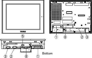
10 Chapter 2 Compatibility of Hardware 2.1 Locations of connector Connector locations of GP/ST-3500 series and GP-4500 series; GP-3500T GP-3500S/L 10/45
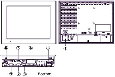
11 ST-3501T/C GP-4501T 11/45
 4 Ethernet I/F - Ethernet I/F 5 USB I/F (Type A) 6 - USB I/F (Type mini B) 7 - SD Card I/F 8 CF Card I/F - 9 Expansion Unit I/F - 10 Auxiliary I/O / Sound Output I/F (AUX) - 12/45")
12 GP-4501TW Interface names GP-3500T GP-3500S/L ST-3501T/C GP-4501T GP-4501TW 1 Power Input Terminal Block (AC) / Power Connector (DC) Power Connector (DC) 2 Serial I/F (COM1) 3 Serial I/F (COM2) 4 Ethernet I/F - Ethernet I/F 5 USB I/F (Type A) 6 - USB I/F (Type mini B) 7 - SD Card I/F 8 CF Card I/F - 9 Expansion Unit I/F - 10 Auxiliary I/O / Sound Output I/F (AUX) - 12/45
13 2.2 Touch Panel Specifications (only when replacing GP-4501T) For replacement with GP-4501T, the Matrix resistive film type which enables simultaneous 2-point touch input or the Analog resistive film type with 1-point touch input only can be selected. When you use 2-point touch input (touching 2 points on the screen at the same time), please select the Matrix resistive film type. PFXGP4501TMA (AC power supply type) or PFXGP4501TMD (DC power supply type) is available. When you replace GP-4501TW (only the Analog resistive film type), unlike GP-3500 series you use, even if two different points are touched at the same time, that s recognized as touch input on the middle coordinates between those two points. GP-4501T Analog Only the first detected touch is effective. Matrix Simultaneous 2-point touch operation is supported. GP-4501TW Analog When two different points are pushed at the same time, touch input on the middle coordinates between those two points is recognized. 13/45


14 2.3 Display Colors (only when replacing GP-3500L or ST-3501C) The display color of GP-3500L and ST-3501C (when using a monochrome mode) is monochrome, but GP-4501TW has a TFT color LCD. After replacement, the display color changes from monochrome to color. When the setting of the display unit type is changed from a monochrome model to a color one on GP-Pro EX, the data may be displayed in colors depending on the GP-Pro EX version or settings of the drawing/the parts on the screens. After changing the display unit type, please confirm the display colors of the drawing or the parts on the screens just in case. If the display is in colors after changing the display unit type GP-Pro EX Ver (Service Pack1) or later supports the function which changes drawing in colors to monochrome. To change the color to monochrome, follow the steps below. (1) Click [Project]->[System Settings]->[Display Unit]. (2) Open the [Display Settings] tab. (3) Change [Color] setting to 16 Levels Monochrome, 3-Speed Blink. * [Reverse Display] setting is for displaying the screen with black/white reversed. Check on this setting if needed. * Please confirm the display colors of the drawing or the parts on the screens after changing the [Color] setting. 14/45
15 2.4 Panel Cutout Dimensions For replacing ST-3501T/C with GP-4501TW, the panel cutout dimensions get larger. It s necessary to process the panel. In other cases, there s no change in the panel cutout dimensions. 2.5 Transfer cable To transfer screen data to GP-4500 series, use a USB transfer cable or Ethernet. The USB cables that can be used for GP-4500 series are as follows; Model Connector Type Connector on GP Options CA3-USBCB-01 USB (Type A) ZC9USCBMB1 Commercial Item - USB (Type mini B) The same USB transfer cable (CA3-USBCB-01) as that for GP/ST-3500 series can be used. 2.6 Interface Serial Interface The pin assignment and the shape of plug/socket connector of ST-3501T/C are the same as those of GP-4500 series, but GP-3500 series are different. To know the details about them, see [4.2 Shapes of COM ports] and [4.3 Signals of COM ports]. Because of it, the existing PLC connection cables cannot be used as they are for GP-3500S/L. If you use the existing connection cables, see [4.5 Cable Diagram at the time of replacement]. When both the COM1 port and the COM2 port have the RS-422/485 setting, only the COM2 port can be used for RS-422/485 connection after replacement. Using a USB/RS-422/485 Conversion Adapter (PFXZCBCBCVUSR41) may allow you to use GP4000 series USB interface as RS-422/485 serial interface for connection. 15/45
16 For more information, please refer to USB/RS-422/485 Conversion Adapter Installation Guide. ( &cat=3) IMPORTANT When using USB/RS-422/485 Conversion Adapter (PFXZCBCBCVUSR41) with a display unit, the device/plcs you can connect to its serial interface (RS-422/485) are limited. To check the connection configuration, please refer to refer to USB/RS-422/485 Conversion Adapter Connection Guide ( m_usc.pdf) CF Card Interface GP-4500 series is not equipped with a CF card slot. But a SD card slot and a USB interfaces are installed. In order to use the GP/ST-3500 series data saved in the CF card and the functions using the CF card, use a SD card or a USB flash drive instead. * When using a SD card with GP-4500 series, please verify it supports the following specifications: File format Maximum capacity SD FAT16 2GB SDHC FAT32 32GB When the setting of the output destination folder is set to CF Card on GP-Pro EX, if you change the display unit type, the setting will automatically change to the one that uses a SD card. 16/45
17 To change the setting of the output destination folder, see [5.1 Changing the setting of the external media to use] USB Interface (for GP-3500 series only) GP-3500T/S/L has two USB ports (USB Type A) but GP-4500 series has only one. If devices are connected to both USB ports on GP-3500 series, use an USB hub for GP-4500 series. Because of bus power limit on GP-4500 series USB port, it s recommended to use an USB hub supporting self-power supply and be sure to check the operation before use. Also, several USB devices of the same category in the following table cannot be simultaneously used. Even if multiple USB devices of the same category are connected to the display unit, only the first USB device recognized by the display unit can be used. USB Devices of the same category Category USB Device 1 Printer, USB-PIO converter 2 Keyboard, Numeric keys, Barcode reader 3 Mouse 4 USB storage (USB memory, CF/SD card reader, and so on) 5 USB transfer cable USB-Serial (RS-232C) conversion cable, SUB/RS-422/485 6 Conversion Adapter Auxiliary I/O Interface (AUX) (for GP-3500 series only) GP-4500 series is not equipped with Auxiliary I/O Feature. External Reset Input and 3 Outputs (RUN Output, System Alarm Output, and External Buzzer Output) that can be used for GP-3500 series cannot be used Sound Output Interface (for GP-3500 series only) GP-4500 series is not equipped with the sound output function. The sound output function for GP-3500 series cannot be used. 17/45
18 2.7 Peripheral units and option units Barcode reader connection Like GP/ST-3500 series, GP-4500 series allows you to connect a barcode reader to its USB interface (Type A) or its serial interface. For the models GP-4500 series supports, see [OtasukePro!] ( Printer connection Like GP/ST-3500 series, GP-4500 series allows you to connect a printer on its USB interface (Type A). For the models GP-4500 series supports, see [OtasukePro!] ( Expansion Unit (for GP-3500 series only) GP-4500 series is not equipped with an expansion unit interface. The expansion unit (each kind of unit like CC-LINK Unit) for GP-3500 series cannot be used Isolation Unit RS-485 isolation unit for GP/ST-3500 series (CA3-ISO485-01) cannot be used for GP-4500 series. You can use the RS-232C isolation unit (CA3-ISO232-01) for GP-4500 series instead. Note for using RS-232C isolation unit (CA3-ISO232-01) Connect it to GP-4500 series via COM1 (232C). COM2 cannot be used. It s necessary to set the 9 th pin of the COM port to VCC. [Settings on GP-ProEX] Select VCC from [System Settings] -> [Device/PLC] in the [Project] menu on GP-Pro EX. RS-422/485 (2-wire type) communication and serial multilink are not supported. 18/45
19 2.8 Power Supply GP-4501TW has a DC power supply type only. When replacing GP/ST-3500 series (AC type) with GP-4501TW, changing to DC power supply is required. If a unit with AC power supply is required, replace GP/ST-3500 series with GP-4501T instead. But please note that the attachment (model no.: CA4-ATM10-01) should be added because the panel cutout demensions are different from GP-3500T/S/L. 2.9 Backup Battery Unlike GP/ST-3500 series, GP4000 series does not use rechargeable secondary batteries but replaceable primary ones. (For both a rechargeable type and a replaceable one, contents to be backed up are the same.) When the time for replacement of backup batteries approaches, the message to urge you to replace the battery, RAAA053: Running out of power in the backup battery. Please change the battery. appears. When the message appears, replace the battery referring to the GP4000 series hardware manual. Replaceable Battery Model PFXZCBBT Power Consumption The power consumption of GP/ST-3500 series is different from that of GP-4500 series. GP-3500T/S AC Type 90VA or less (AC100V) 108VA or less (AC240V) DC Type 50W or less GP-3500L - ST-3501T/C 90VA or less (AC100V) 108VA or less (AC240V) 45W or less GP-4501T/TW - 17W or less For the detailed electric specifications, see the hardware manual Materials/Colors of the body The materials and the colors of GP/ST-3500 series and GP-4500 series are as follows: 19/45
 When replacing GP-3500S/L or ST-3501T/C with GP-4501TW, SRAM size becomes smaller (320KB -> 128KB).")
20 Color Material GP-3500 series Silver Aluminum alloy ST-3500 series GP-4500 series Light Gray Resin Resin with glass 2.12 Backup Memory (SRAM) When replacing GP-3500S/L or ST-3501T/C with GP-4501TW, SRAM size becomes smaller (320KB -> 128KB). In case that SRAM size of your project file is more than 128KB after changing the Display Unit type to GP-4501TW, replace GP-3500S/L or ST-3501T/C with GP-4501T instead of GP-4501TW. To check SRAM size, follow the steps below; (1) Double click and open the project file (*.prx) on GP-Pro EX. (2) Change the Display Unit type of your project file to GP-4501TW. To know how to do it, see [3.4 Change the Display Unit Type]. (3) Click [Project]->[Information]->[Project Information]. The Project Information window appears. (4) Click [SRAM Information] to see SRAM size. 20/45
21 Chapter 3 Replacement Procedure 3.1 Work Flow Installation Screen Communication Check the compatibility of hardware in Chapter 2. Remove GP/ST-3500 series. Receive screen data from GP/ST-3500 series. *1 Change the received data on GP-Pro EX. Check the connection between GP4500 series and a PLC in the GP-Pro EX Device/PLC Connection Manual. When replacing GP/ST-3500 series to GP-4500 series process the panel. Check and modify the data on GP-Pro EX. Install GP-4500 series. Transfer the screen data to GP-4500 series. Connect GP-4500 series and PLC with the PLC s bl Connect the power cord. Start connection and check the communi- cation. Check the performance and start operation. *1: This step is required if screen data is saved only in the GP unit, not in any other device. 21/45
22 3.2 Preparation Requirements for receiving screen data from GP/ST-3500 series *1 Requirements for converting screen data of GP/ST-3500 series and transferring the converted data to GP-4500 series. PC in which GP-Pro EX Transfer Tool is installed. *2 USB Transfer Cable (model: CA3-USBCB-01) * Possible to send/receive a screen via a CF card, a USB storage device or Ethernet (for GP-3500 series only). PC in which GP-Pro EX Ver.3.01 or later is installed. Transfer Cable (The following three types of cables are available) A USB transfer cable (model: CA3-USBCB-01) A USB data-transfer cable (model: ZC9USCBMB1) A commercial USB cable (USB Type A/mini B) * Possible to send/receive a screen via a SD card, a USB storage device or Ethernet. *1: This step is required if screen data is saved only in the GP unit, not in any other device. *2: Please use the same version or later as or than that of the software used during creating screens on GP/ST-3500 series. If you don t know the version, we recommend you to use the newest version. For the newest version, you can download the transfer tool from our web site called [OtasukePro!] ( 22/45
23 3.3 Receive screen data from GP/ST-3500 series You can transfer data to GP/ST-3500 series via; A USB transfer cable (model: CA3-USBCB-01) A CF card/usb storage device Ethernet (for GP-3500 series only) But this section explains, as an example, how to receive screen data from GP/ST-3500 series using a USB transfer cable (model: CA3-USBCB-01). If you have backed up screen data, this step is unnecessary, skip to the next section [3.4 Change the Display Unit Type]. 23/45
24 (1) Connect your PC and GP/ST-3500 series with a USB transfer cable. If the driver of the cable has not been installed on your PC yet, a dialog box will appear. Please follow the instructions. NOTE The Hardware Installation dialog box as shown below may appear during installing the USB driver depending on the security level of Windows XP. Click [Continue Anyway] to start installing the driver. When installation is completed, click [Finish]. If the following symptoms appear on Microsoft Windows 7, go to updating USB Data Transfer Driver on [OtasukePro!] for download. ( m) - An error occurs when GP-Pro EX or Transfer Tool is installed - An error occurs when data is transferred via a USB transfer cable (model: CA3-USBCB-01). 24/45
25 (2) Start the Transfer Tool of GP-Pro EX. (3) Make sure that the [Device] in the Transfer Settings Information is set to [USB]. If not, click the [Transfer Setting] button to open the Transfer Setting dialog box. Select [USB] in the Communication Port Settings field and click [OK]. 25/45

![(5) Click [Receive Project], and the following dialog box](/docs-images/73/68849557/images/26-1.jpg "will appear.")

26 (4) Start GP-Pro EX Transfer Tool and click the [Receive Project] button. (5) Click [Receive Project], and the following dialog box will appear. Specify a place to save the received data in and a project file name, and then click [Save] to start transfer. NOTE When a file exists, the window that confirms whether or not to overwrite the file is displayed. 26/45

27 (6) The following dialog box appears during transfer and you can check the communication status. (The display unit enters the Transferring mode and communication with the device such as a PLC is terminated.) Display Screen NOTE If you receive the project files that use CF card data such as Recipe Function (CSV data), the following dialog box will appear during transfer. Specify a place to save the CF card data in. Click [OK], and the [Receive Project] dialog box will return and transfer will be completed. GP-4500 series that is a replacement model is not equipped with a CF card slot. If the display unit type is changed to GP-4500 series, the CF card setting will be replaced with the SD card setting automatically. To check or change the destination folder setting, see [5.1 Changing the setting of the external media to use]. 27/45
28 (7) When transfer is completed, the status displayed in the dialog box will change from [Transferring] to [Complete Transfer]. Click [Close] to close the dialog box. (8) Close the Transfer Tool. 3.4 Change the Display Unit Type Open the received project file (*.prx) of GP/ST-3500 series on GP-Pro EX and change the display unit type to GP-4500 series. (1) Open the received project file (*.prx) on GP-Pro EX. (2) Click [System Settings]->[Display]->[Change Display] in [Project] menu and change the Display Unit type to the replacement model. (3) Click [Project]->[Save As] and save the changed project file. 28/45
29 3.5 Transfer the screen data to GP-4500 series Transfer the project file after the display unit type change to GP-4500 series. You can transfer data to GP-4500 series via; An USB transfer cable (model: CA3-USBCB-01) An USB data transfer cable (model: ZC9USCBMB1) A commercial USB cable (USB Type A/mini B) A SD card/usb storage device Ethernet But, this section explains, as an example, how to transfer screen data with an USB transfer cable (model: CA3-USBCB-01). 29/45
30 (1) Connect your PC and the GP unit of GP-4500 series with a USB transfer cable. If the driver of the cable has not been installed on you PC, a dialog box will appear. Please follow the instructions. NOTE The Hardware Installation dialog box as shown below may appear during installing the USB driver depending on the security level of Windows XP. Click [Continue Anyway] to start installing the driver. When installation is completed, click [Finish]. If the following symptoms appear on Microsoft Windows 7, go to updating USB Data Transfer Driver on [OtasukePro!] for download ( m). - An error occurs when GP-Pro EX or Transfer Tool is installed - An error occurs when data is transferred via a USB transfer cable (model: CA3-USBCB-01). 30/45

 On the GP-Pro EX s State Toolbar, click the [Transfer Project] icon to open the Transfer")
31 (2) Trun on the power of GP-4500 series. The Initial Start Mode screen will appear on the display unit. After transferring a project file once, this screen will not appear again. (3) On the GP-Pro EX s State Toolbar, click the [Transfer Project] icon to open the Transfer Tool. To transfer a different project file, click the [Select Project] button and select a project file. 31/45
![(4) Make sure that the [Device] in the Transfer Settings Information is set to [USB].](/docs-images/73/68849557/images/32-0.jpg "If not, click the [Transfer Setting] button to open the Transfer Setting dialog box. Select [USB] in the Communication Port Settings field and click [OK].")
![(5) Click [Send Project] to start transfer. When the following dialog box appears, click [Yes].](/docs-images/73/68849557/images/32-2.jpg "This dialog box doesn t appear when the same project file is sent again.")
32 (4) Make sure that the [Device] in the Transfer Settings Information is set to [USB]. If not, click the [Transfer Setting] button to open the Transfer Setting dialog box. Select [USB] in the Communication Port Settings field and click [OK]. (5) Click [Send Project] to start transfer. When the following dialog box appears, click [Yes]. This dialog box doesn t appear when the same project file is sent again. (6) The following dialog box appears during transfer and you can check the communication status. (The display unit enters the Transferring mode and communication with the device such as a PLC is terminated.) Display Screen 32/45
![(7) When transfer is completed, the status displayed in the dialog box will change from [Transferring] to [Complete Transfer]. Click [Close] to close the dialog box.](/docs-images/73/68849557/images/33-0.jpg "The display unit will be reset and a screen of the transferred project file will be displayed. (8) Close the Transfer Tool.")
33 (7) When transfer is completed, the status displayed in the dialog box will change from [Transferring] to [Complete Transfer]. Click [Close] to close the dialog box. The display unit will be reset and a screen of the transferred project file will be displayed. (8) Close the Transfer Tool. (9) Click the [X] mark on top right of the screen or [Project]->[Exit] to close GP-Pro EX. 3.6 Differences of software Some functions supported by GP/ST-3500 series are not supported by GP-4500 series. For details of the supported parts and functions, refer to [Supported Featuers] of GP-Pro EX Reference Manual ( 33/45
34 Chapter 4 Communication with Device/PLC 4.1 Drivers Connectable Devices More connectable drivers will be added. For the devices/plc each driver supports, see [Connectable Devices] ( Connecting to Multiple Device/PLCs (only when replacing GP-4501TW) GP-3500S/L can communicate with multiple device/plcs simultaneously with four drivers (COM1, COM2 and Ethernet), but GP-4501TW with two drivers only. Check out the table below to see which model is appropriate for replacement depending on the state of the connection with your Device/PLC. Number of Device/PLC Drivers *1 GP-3500S/L Connection Replacement Model 1 Any connection GP-4501TW 2 COM1: RS-422/485 COM2: RS-422/485 Ethernet connection All other connections 3 or more COM1: RS-422/485 COM2: RS-422/485 Ethernet connection All other connections GP-4501TW with USB/RS-422/485 Conversion Adapter (PFXZCBCBCVUSR41) *2 GP-4501TW GP-4501T with USB/RS-422/485 Conversion Adapter (PFXZCBCBCVUSR41) *2 GP-4501T *1: To see the number of device/plc drivers, click [System Settings] -> [Device/PLC] from the [Project] menu on GP-Pro EX. *2: About USB/RS-422/485 Conversion Adapter (PFXZCBCBCVUSR41), be sure to read [2.5.1 Serial Interface] for details before use. 34/45
35 4.2 Shapes of COM ports GP-3500T/S/L ST-3501T/C GP-4501T/TW D-Sub 9 pin (plug) RS-232C/422/485 D-Sub 9 pin (plug) RS-232C COM1 D-Sub 9 pin (socket) RS-422/485 D-Sub 9 pin (plug) RS-422/485 COM2 35/45
36 4.3 Signals of COM ports Signals of COM1 For GP-3500T/S/L RS-232C (plug) *1: RI and VICC of Pin 9 are switched on the software. VCC Output is not protected from overcurrent. Please follow the current rating to avoid false operation or breakdown. RS-422/485 (plug) 36/45
37 For ST-3501T/C RS-232C (plug) *1: RI and VICC of Pin 9 are switched on the software. VCC Output is not protected from overcurrent. Please follow the current rating to avoid false operation or breakdown. 37/45
38 For GP-4501T/TW RS-232C (plug) *1: RI and VICC of Pin 9 are switched on the software. VCC Output is not protected from overcurrent. Please follow the current rating to avoid false operation or breakdown Signals of COM2 For GP-3500T/S/L RS-422/485 (socket) For ST-3501T/C 38/45
39 RS-422/485 (plug) For GP-4501T/TW RS-422/485 (plug) 4.4 Multilink Connection For the communication drivers that support serial multi-link, see [Which drivers support serial multilink communication?] ( m). 39/45

 Before GP-4500 series is connected, be sure to change the port setting to COM2 on the Device/PLC setting.")
40 4.5 Cable Diagram at the time of replacement The pin assignment and the shape of plug/socket connector of ST-3501T/C are the same as those of GP-4501 series, but GP-3500 series are different. Please note that there are precautions and restrictions as described below when replacing GP-3500 series. When a RS-422/485 device is connected via the COM1 port, if GP-3500 series is replaced with GP-4500 series, it will be connected via the COM2 port of GP-4500 series. (The cable diagram can be still used.) Before GP-4500 series is connected, be sure to change the port setting to COM2 on the Device/PLC setting. Also, please check the communication settings with GP-Pro EX Device/PLC Connection Manual just in case. ( ) 40/45
41 The cable used for connection to GP-3500 series via COM2 can be used for GP-4500 series with a COM Port Conversion Adapter (CA3-ADPCOM-01) added in the following cases; In all other cases, the operation is not guaranteed and it's recommended to prepare a new connection cable. To check the cable diagram, please refer to GP-Pro EX Device/PLC Connection Manual. 41/45
42 Important If the homemade COM 2 cable diagram for GP-3500 series is used for GP-4501T/TW with a COM port conversion adapter (CA3-ADPCOM-01), no operation is guaranteed. It s recommended to get a new cable diagram prepared for GP-4501T/TW. For cable diagrams, see GP-Pro EX Device/PLC Connection Manual. ( m) When both the COM1 port and the COM2 port have the RS-422/485 setting, only the COM2 port can be used for RS-422/485 connection after replacement with GP4000 series. Using a USB/RS-422/485 Conversion Adapter may allow you to use GP4000 series USB interface as RS-422/485 serial interface for connection. For more information, please refer to USB/RS-422/485 Conversion Adapter Installation Guide. ( &cat=3) Important The connected devices/plc which can connect to the serial interface side of USB/RS-422/485 Conversion Adapter are limited. For details, see USB/RS-422/485 Conversion Adapter Connection Guide ( m_usc.pdf) Chapter 5 Appendix 5.1 Changing the setting of the external media to use If a CF card is used for GP/ST-3500 series, after the display unit type of the project file 42/45
43 is changed to GP-4500 series, a CF card is automatically replaced with a SD card for the external media setting. (1) After conversion of the project file data, at GP-Pro EX Error Check, if the message, The project contains features that require a SD card. However, the selected display does not support SD cards so these features will not run. appears, <Cause> The model without a SD card slot has the setting that uses a SD card. ->Solution 1 (2) To use a USB flash drive instead of a SD card ->Solution 1 (3) To check or change the SD card s data output destination folder setting ->Solution 2 [Solution] 1. Change the SD Card setting to the USB storage setting following the steps below. 43/45
44 <Procedure> i. Click [Project]->[Information]->[Destination Folder]. ii. Uncheck Enable SD Card and check Enable USB Storage. iii. Click the [Browse] button and specify a destination folder. iv. Click [OK] to confirm the setting. v. Click [Project]->[Save] to save changes. vi. Check each function that uses the CF card and replace the setting of [SD Card] with the one of [USB Storage]. NOTE To check each function setting of GP-Pro EX, refer to GP-Pro EX Reference Manual. 44/45
![2. Check and change the destination folder setting following the steps below. i. Click [Project]->[Information]->[Destination Folder]. ii.](/docs-images/73/68849557/images/45-0.jpg "The current setting is displayed. iii. After changing it, click [OK] to confirm the setting. iv. Click [Project]->[Save] to save changes.")
45 2. Check and change the destination folder setting following the steps below. i. Click [Project]->[Information]->[Destination Folder]. ii. The current setting is displayed. iii. After changing it, click [OK] to confirm the setting. iv. Click [Project]->[Save] to save changes. 45/45
Easy! Smooth! GP3600 Series->GP4600 Series Replacement Guidebook
 Easy! Smooth! GP3600 Series->GP4600 Series Replacement Guidebook 1/34 The 6th Edition April 2013 Copyright 2013.4 Digital Electronics Corporation. All Rights Reserved. Preface This guidebook introduces
Easy! Smooth! GP-3310T->GP4000 Series Replacement Guidebook
 Easy! Smooth! GP-3310T->GP4000 Series Replacement Guidebook 1 First Edition Jul. 2012 Copyright 2012.7 Digital Electronics Corporation. All Rights Reserved. Preface This guidebook introduces the procedures
Easy! Smooth! GP-3310, GP-3360, GP/ST-3400 Series ->GP4000 Series Replacement Guidebook
 Easy! Smooth! GP-3310, GP-3360, GP/ST-3400 Series ->GP4000 Series Replacement Guidebook 1/44 7th Edition Apr. 2017 Copyright 2012.8 Digital Electronics Corporation. All Rights Reserved. Preface This guidebook
Easy! Smooth! GP/ST-3300 Series GP4000 Series. Replacement Guidebook. Copyright Digital Electronics Corporation. All Rights Reserved.
 Easy! Smooth! GP/ST-3300 Series GP4000 Series Replacement Guidebook 1 Third Edition Apr. 2012 Copyright 2012.4 Digital Electronics Corporation. All Rights Reserved. Preface This guidebook introduces the
Easy! Smooth! ST-3300 Series->GP4000 Series Replacement Guidebook
 Easy! Smooth! ST-3300 Series->GP4000 Series Replacement Guidebook 1 Fifth Edition Jul. 2012 Copyright 2012.7 Digital Electronics Corporation. All Rights Reserved. Preface This guidebook introduces the
GP-577R Series GP4000 Series. Replacement Guidebook 1/48. Second Edition Mar. 2012
 GP-577R Series GP4000 Series Replacement Guidebook 1/48 Second Edition Mar. 2012 Copyright 2012.3 Digital Electronics Corporation. All Rights Reserved. Preface This manual introduces the procedures to
Easy! Smooth! GP-2500 Series->GP4000 Series Replacement Guidebook
 Easy! Smooth! GP-2500 Series->GP4000 Series Replacement Guidebook 1/51 5 th Edition 2014.11 Copyright 2014.11 Digital Electronics Corporation. All Rights Reserved. Preface This guidebook introduces the
Easy! Smooth! ST-400 Series->GP4000 Series Replacement Guidebook
 Easy! Smooth! ST-400 Series->GP4000 Series Replacement Guidebook 1/44 5th Edition Jul. 2012 Copyright 2012.9 Digital Electronics Corporation. All Rights Reserved. Preface This manual introduces the procedures
Easy! Smooth! GP-2600 Series GP4000 Series
 Easy! Smooth! GP-2600 Series GP4000 Series Replacement Guidebook 1/52 3rd Edition 2014.11 Copyright 2014.11 Digital Electronics Corporation. All Rights Reserved. Preface This guidebook introduces the procedures
GP-37W2->GP4000 Series Replacement Guidebook
 GP-37W2->GP4000 Series Replacement Guidebook 1/41 Third Edition Jul. 2012 Copyright 2012.7 Digital Electronics Corporation. All Rights Reserved. Preface This manual introduces the procedures to replace
Easy! Smooth! GP-577R Series GP4000 Series. Replacement Guidebook 1/52. 3rd Edition
 Easy! Smooth! GP-577R Series GP4000 Series Replacement Guidebook 1/52 3rd Edition 2014.11 Copyright 2014.11 Digital Electronics Corporation. All Rights Reserved. Preface This manual introduces the procedures
Replacement Guidebook
 Easy! Smooth! Replacement Guidebook GP-3510T Series ->SP-5500TP(Premium Display) + SP-5B10(Power Box) 1/28 The 3rd Edition 2014.11 Copyright 2014.11 Digital Electronics Corporation. All Rights Reserved.
Easy! Smooth! GP-37W2->GP4000 Series Replacement Guidebook
 Easy! Smooth! GP-37W2->GP4000 Series Replacement Guidebook 1/45 4th Edition 2014.11 Copyright 2014.11 Digital Electronics Corporation. All Rights Reserved. Preface This manual introduces the procedures
Replacement Guidebook
 Easy! Smooth! Replacement Guidebook GP-3750T ->SP-5700TP(Premium Display) + SP-5B10(Power Box) The 3rd Edition 2017.6 Preface This guidebook introduces the procedures to replace a unit in GP-3750T series
GP-2301S/L->GP4000M Series Replacement Guidebook
 GP-2301S/L->GP4000M Series Replacement Guidebook 1/45 Third Edition Jul. 2012 Copyright 2012.7 Digital Electronics Corporation. All Rights Reserved. Preface This guidebook introduces the procedures to
Replacement Guidebook
 Easy! Smooth! Replacement Guidebook GP-3300T, GP-3310T, GP-3360T Series ->SP-5400WA(Advanced Display) + SP-5B10(Power Box) 1/32 The 5th Edition Jun. 2017 Copyright 2014.11 Digital Electronics Corporation.
Easy! Smooth! GP-2301S/L->GP4000M Series Replacement Guidebook
 Easy! Smooth! GP-2301S/L->GP4000M Series Replacement Guidebook 1/48 4th Edition 2014.11 Copyright 2014.11 Digital Electronics Corporation. All Rights Reserved. Preface This guidebook introduces the procedures
Replacement Guidebook GP3000U SP5000X
 Replacement Guidebook GP3000U SP5000X The First Edition Feb.2019 Preface This guidebook introduces the procedures to replace a unit in GP3000U series with a SP5000X Series. Model in use Model No. Recommended
Replacement Guidebook
 GP-37W2 GP4000M Series Replacement Guidebook 1/42 Second Edition Apr. 2012 Copyright 2012.4 Digital Electronics Corporation. All Rights Reserved. Preface This manual introduces the procedures to replace
Easy! Smooth! ST400 Series->GP4000M Series Replacement Guidebook
 Easy! Smooth! ST400 Series->GP4000M Series Replacement Guidebook 1/39 Second Edition Apr. 2012 Copyright 2012.4 Digital Electronics Corporation. All Rights Reserved. Preface This guidebook introduces the
Preface. For the replacement of GP-2601T, 2501S, please refer to GP2000 series replacement booklet. Third Edition: Feb /38
 1/38 Preface This manual introduces the procedures to replace the unit in the GP2*01 series (GP-2501T, GP-2401T, GP-2301T/L) with the ST3000 series (AST-3501T, AST-3401T, AST-3301T/S/B). The recommended
Preface GP-3300L GP-3500T GP-2601T GP-2500S GP-2501S GP-3500S
 1/43 Preface This manual introduces the procedures to replace the unit in the GP2000 series (GP-2600T, GP-2601T, GP-2500T, GP-2500S, GP-2501S, GP-2400T, GP-2300T/L) with the GP3000 series (GP-3600T, GP-3500T,
PFXGR4301TAD. Pro-face Xycom GP4000 PFXGR4301TAD
 PFXGR4301TAD http://www.axcontrol.com/automation/pro-face/gp-4000/pfxgr4301tad Pro-face Xycom GP4000 PFXGR4301TAD Pro-face Xycom GP-4301T GP4301T Touch Screen Operator Interface 5.7 TFT Color LCD Display.
Easy! Smooth! GP3000H GP4000H (by GP-Pro EX) Replacement Guidebook
 Replacement Guidebook") Easy! Smooth! GP3000H GP4000H (by GP-Pro EX) Replacement Guidebook 2nd Edition Nov. 2016 Copyright 2012.9 Digital Electronics Corporation. All Rights Reserved. 1 Introduction Replacement / Model Code Equipment
Easy! Smooth! GP3000H GP4000H (by GP-Pro EX) Replacement Guidebook 2nd Edition Nov. 2016 Copyright 2012.9 Digital Electronics Corporation. All Rights Reserved. 1 Introduction Replacement / Model Code Equipment
Introduction. Summary. Otasuke GP-EX! Introduction Summary. Intro-21. Development Environment Intro-4. Procedures of Creating New Screen
 Introduction Summary Summary Intro-1 Development Environment Intro-4 Procedures of Creating New Screen Intro-5 Main Window Intro-6 Tips for man-hours reduction ~Full use of Work Space~ Intro-10 Simulation
Preface. Safety Information
 1/43 Preface This manual introduces the procedures to replace the unit in the GLC2000 series (GLC2600T, GLC2500T, GLC2400T, 2300T/L) with the GP3000 series C class, FLEX NETWORK type (GP-3600T-FN1M, GP-3500T-FN1M,
1/5 Copyright (C) 2012 Digital Electronics Corporation. All rights reserved.
 2012 Digital Electronics Corporation. All rights reserved.") Main Unit Model No. Global Code Description GP4104G1D PFXGP4104G1D 3.4-inch Compact Type. Interface: Ethernet. Display Colors: Monochrome Green/Red/Orange. Power Supply: DC. GP4104W1D PFXGP4104W1D 3.4-inch
Main Unit Model No. Global Code Description GP4104G1D PFXGP4104G1D 3.4-inch Compact Type. Interface: Ethernet. Display Colors: Monochrome Green/Red/Orange. Power Supply: DC. GP4104W1D PFXGP4104W1D 3.4-inch
PL-590*T Replacement Guidebook
 Easy! Smooth! Replacement Guidebook 1/28 Preface Thank you very much for using Pro-face panel computers. Thanks to your continued support, the 10.4-inch PL-5910 series introduced in January 2005 and its
Screen Data Adjustment Manual
 Screen Data Adjustment Manual (Upgrading to AGP/AST Series) 1/53 Dec-2008 Rev 1 Index IS THERE ANY TWO-POINT PUSH TOUCH OPERATION?... 3 IS ANY WINDOW SCREEN CALLED WHEN A MOMENTARY SWITCH IS PRESSED?...
1 Troubleshooting 1-1
 1 Troubleshooting This chapter describes solutions for problems you may encounter while using the GP3000 series. Read the section describing the problem you are encountering. 1.1 Identifying the problem...1-2
PL-79** Series Replacement Guidebook
 Easy! Smooth! PL-79** Series Replacement Guidebook 1/35 Preface This guidebook introduces the procedures to replace your unit in the PL-79** series with the PL3000 or PS3000 series. The recommended replacement
PFXGP4503TAD. Pro-face Xycom GP4000 PFXGP4503TAD
 PFXGP4503TAD http://www.axcontrol.com/automation/pro-face/gp-4000/pfxgp4503tad Pro-face Xycom GP4000 PFXGP4503TAD Pro-face Xycom GP-450xT GP450xT Touch Screen Operator Interface 10.4 TFT Analog Color LCD
Touch Operator Interface GP4000SERIES.
 Touch Operator Interface GP4000SERIES www.proface.com GP4000 SERIES L i n e up Standard Model 12.1" 10.4" Color variation Color variation 7.5" AC 100-240V DC 24V AC 100-240V DC 24V DC 24V DC 24V DC 24V
User Manual. cmt-iv5 Startup Guide
 User Manual cmt-iv5 Startup Guide v 2.2 JAN 8, 2016 Table of Contents Chapter1. Overview... 1 1.1. Specification... 1 1.2. Dimensions... 2 1.3. Ethernet port... 3 1.4. CR1225 battery... 3 1.5. Power connection...
PL-69** Series Replacement Guidebook
 Easy! Smooth! PL-69** Series Replacement Guidebook 1/27 Preface This guidebook introduces the procedures to replace your unit in the PL-69** series with the PL3000 or PS3000 series. The recommended replacement
Industrial Control SE-607
 Industrial Control SE-607 Controller and visualization combined as an automation solution with infrared touch operation Trend-setting industrial controls for heat treatment plants The controller is equipped
UniOP epad30, epad32. Tech-note PN# tn171-3.doc - 03/10/ Ver Highlights
 UniOP epad30, epad32 The epad30 and 32 are state-of-the-art HMI devices with a 10.4 graphic display (9.6 for the monochrome version) and a complete keypad. The aluminum bezel offers an appealing look in
PL-69** Series Replacement Guidebook
 Easy! Smooth! PL-69** Series Replacement Guidebook 1/27 Preface This guidebook introduces the procedures to replace your unit in the PL-69** series with the PL3000 or PS3000 series. The recommended replacement
Easy! Smooth! GP2000H Series Replacement Guidebook
 Easy! Smooth! GP2000H Series Replacement Guidebook 1/56 Preface This guidebook introduces the procedures to replace the unit in the GP2000H series (GP-2401HT, GP-2301HS/L) with the GP3000H series (GP-3310HT,
PFXGP4601TAD. Pro-face Xycom GP4000 PFXGP4601TAD
 PFXGP4601TAD http://www.axcontrol.com/automation/pro-face/gp-4000/pfxgp4601tad Pro-face Xycom GP4000 PFXGP4601TAD Pro-face Xycom GP-460xT GP460xT Touch Screen Operator Interface 12.1 TFT Analog Color LCD
GTWIN 1.1 CONTROL TECHNOLOGY CORPORATION. GTWIN 2.8 Quick Start. MGT Panel & GTWIN Quick Start Guide
 GTWIN 1.1 CONTROL TECHNOLOGY CORPORATION GTWIN 2.8 Quick Start MGT Panel & GTWIN Quick Start Guide CONTROL TECHNOLOGY CORPORATION MGT Panel & GTWIN Quick Start Guide Copyright 2004-2007 Control Technology
CPU-02 Module (Model: JAPMC - CP2210)
") CPU Module for MP2200 Machine Controller CPU-02 Module (Model: JAPMC - CP2210) Guide for Connections and Operations 1.1 How to Connect the CPU-02 Module - - - - - - - - - - - - - - - - - - - 2 1.1.1 Connecting
CPU Module for MP2200 Machine Controller CPU-02 Module (Model: JAPMC - CP2210) Guide for Connections and Operations 1.1 How to Connect the CPU-02 Module - - - - - - - - - - - - - - - - - - - 2 1.1.1 Connecting
Power Panel Integrated control, operation and visualization
 Power Panel Integrated control, operation and visualization The compact and intelligent PP15, PP21, and PP41 Power Panel devices are the fi rst choice for automating small to mid-sized machines and systems
Control Panel CP600 CP651, CP651-WEB
 DATA SHEET Control Panel CP600 CP651, CP651-WEB 1 Ordering Data Part No. Description Product Life Cycle Phase 1SAP551100R0001 CP651, control panel, TFT graphical display, single-touch screen, 10.4, Active
EMBEDDED HARDWARE. Core Board. ARM7 Development board. ARM7 Evaluation Board. Page 1 of 5
 Core Board * Size: 71.2mm *50.8mm * Industrial grade 32-bit RISC micro-controller * Mass storage device support * Industrial grade 16C550 Serial Interface * 10/100M Industrial Ethernet interface * USB
Machine TV Interface. mtv-100. Memory Processor. I/O Port RTC. Power. Specification. Certificate Software
 Machine TV Interface Features HD 720p High Resolution HDMI Output One Gigabit Ethernet Port Compact Design and DIN-rail Mountable Built-in 256MB Flash Memory SD Card Slot for Extension of Storage One USB
32.1 Settings Menu. Settings Menu. GP-Pro EX Reference Manual Checking the Display operation on the PC.
 32 Simulation This chapter provides an overview of the "Simulation" feature of GP-Pro EX and the basic operation for the simulation. Begin reading "32.1 Settings Menu" (page 32-2) and proceed to the description
UniOP epad03 and epad04
 UniOP epad03 and epad04 Compact low-cost HMI with graphic display. The epad03 and epad04 panels are defining a new standard for entry-level HMI products. They are the ideal replacement for the successful
Control Panel CP600 CP635, CP635-B, CP635-WEB
 DATA SHEET Control Panel CP600 CP635, CP635-B, CP635-WEB 1 Ordering Data Part No. Description Product Life Cycle Phase 1SAP535100R0001 CP635, control panel, TFT graphical display, single-touch screen,
PFXGP4501TADC. Pro-face Xycom GP4000 PFXGP4501TADC
 PFXGP4501TADC http://www.axcontrol.com/automation/pro-face/gp-4000/pfxgp4501tadc Pro-face Xycom GP4000 PFXGP4501TADC Pro-face Xycom GP-450xT GP450xT Touch Screen Operator Interface 10.4 TFT Analog Color
A Series CPU Direct Driver
 Mitsubishi Electric Corporation A Series CPU Direct Driver 1 System Configuration... 3 2 Selection of External Device... 8 3 Example of Communication Setting... 9 4 Setup Items...12 5 Cable Diagram...
EU DECLARATION OF CONFORMITY
 GP4000 Seires Digit 1 2 3 4 5 6 7 8 9 10 11 12 13 GP4000M Seires P F X model series size interface LCD touch GP 4 2: 3.5 3: 5.7 4: 7 /7.5 5: 10.4 6: 12.1 01: Normal 03: RS-485 (Iso) 21: Video unit T: W:
TPM Operation Manual
 Revision 1.1 July 17, 2017 TPM Operation Manual Parameter setting, monitoring and auto data memory for MDC & ADC www.mountztorque.com - 1080 N 11th St - San Jose CA 95112-408.292.2214 1 Index 1. Main feature
System concept. Hardware DATA SHEET VECTRON POS TOUCH 12 LIGHT
 System concept The Vectron POS Touch 12 Light has been developed for the highest demands. Thanks to its outstanding features, Vectron POS Touch 12 Light is particularly suitable for use in difficult environments
PFM-LNP. PC/104 Modules. Features. Specifications. Packing List. PC/104 Module With Intel Atom N450 Processor Intel Atom N450 1.
 PFM-LNP Module With Intel Atom N450 Processor Modules Front Panel LAN LED Keyboard & Mouse Power USB SATA SATA Power COM VGA LVDS Intel Atom N450 1.66 GHz Processor Intel ICH8M Onboard DDR2 667 Memory,
4-1. This chapter explains HMI settings.
 4-1 4. Hardware Settings This chapter explains HMI settings. 4.1. Overview... 4-2 4.2. I/O Ports... 4-2 4.3. LED Indicators... 4-2 4.4. System Reset... 4-3 4.5. System Toolbar... 4-4 4.6. System Setting
FUJI UG SERIES PROGRAMMABLE OPERATION DISPLAY USER S MANUAL. <Notes on Using UG221H- LE4, LR4> TYPE: UG221H-LE4 UG221H-LR4 FEH374
 FUJI UG SERIES PROGRAMMABLE OPERATION DISPLAY USER S MANUAL TYPE: UG221H-LE4 UG221H-LR4 FEH374 Preface This manual explains the notes and the limits for using UG221H-LE(R)4.
2 Preparation. 2.1 Items to Check Connecting PC with GP Setting PC Network Setting GP Network
 2 Preparation 2.1 Items to Check...2-2 2.2 Connecting PC with GP...2-6 2.3 Setting PC Network...2-9 2.4 Setting GP Network...2-21 Pro-Server EX Reference Manual 2-1 Items to Check 2.1 Items to Check Before
Remote PC Operation Screen (RPA) 10-1 Virtual Network Computing (VNC) Set up Server (VNC) Remote PC Access Set Key Code 10-10
 10-1 Virtual Network Computing (VNC) Set up Server (VNC) Remote PC Access Set Key Code 10-10") Chapter 10 Remote PC Operation Screen (RPA) Remote PC Operation Screen (RPA) 10-1 Virtual Network Computing (VNC) 10-3 Set up Server (VNC) 10-4 Remote PC Access 10-8 Set Key Code 10-10 Let s Set RPA 10-12
Chapter 10 Remote PC Operation Screen (RPA) Remote PC Operation Screen (RPA) 10-1 Virtual Network Computing (VNC) 10-3 Set up Server (VNC) 10-4 Remote PC Access 10-8 Set Key Code 10-10 Let s Set RPA 10-12
PE-4000B PS-5001B Replacement Guidebook
 PE-4000B PS-5001B Replacement Guidebook 1 Initial Edition Dec. 2018 Copyright 2012.9 Digital Electronics Corporation. All Rights Reserved. Introduction This document introduces the procedures and notes
8.1 Settings Menu. Settings Menu
 8 Bar Code This chapter provides a basic explanation of the operation of the "Bar Code" on the GP-Pro EX. Please read For more information, see 8.1 Settings Menu on page 8-2., and skip to the required
17 Writing the display unit s Filing Data to Excel
 17 Writing the display unit s Filing Data to Excel 17.1...17-2 17.2 Setting Guide...17-22 17-1 17.1 Refer to the 'GP-Pro Ex Reference Manual' for more details about filing data. [Action Example] Detect
Chapter 8. Recipe Input Screen. Otasuke GP-EX! Chapter 8 Recipe Input Screen 8-0. Recipe Input Screen 8-1. Perform/Set up Recipe Feature 8-2
 Chapter 8 Recipe Input Screen Recipe Input Screen 8- Perform/Set up Recipe Feature 8- Let s Enter Data from Recipe 8-5 Let s Check Recipe Data on Display Unit 8-0 How to set [Security] 8-3 Let s Create
USB Data Transfer Cable CA3-USBCB-01 Installation Guide
 USB Data Transfer Cable CA3-USBCB-01 Installation Guide Safety Precautions This guide contains a variety of safety markings related to the safe and correct operation of the USB Data Transfer Cable. Be
PANEL-MOUNTED INDUSTRIAL PC. ports (Ethernet, USB, serials, parallel, peripherals commonly utilized in the industrial
 DIGISTAR II PANEL-MOUNTED INDUSTRIAL PC Main applications Supervision of industrial processes Gateway between field and mainframe Application in critical environments Data centralization Human-machine
Technical Specifications: Dell OptiPlex GX150 System
 Technical Specifications: Dell OptiPlex GX150 System Processor Microprocessor type Internal cache Intel Pentium III or Celeron microprocessor 32-kilobyte (KB) first-level (16-KB data cache; 16-KB instruction
7 Device/PLC Communication
 7 Device/PLC Communication This chapter explains how to use the display unit to communicate with multiple devices/ PLCs. Procedures for stopping communications and changing devices/plcs are also discussed.
Hi5 Robot Driver. Hyundai Heavy Industries
 Hyundai Heavy Industries Hi Robot Driver System Configuration... 3 2 Selection of... 7 3 Example of Communication Setting... 8 Setup Items... Cable Diagram... 2 Supported Device... 32 7 Device Code and
User s Manual. PC-Based Measurement Instruments. Setup Guide for Windows Vista IM E. 1st Edition
 User s Manual PC-Based Measurement Instruments Setup Guide for Windows Vista 1st Edition Thank you for purchasing the PC-Based Measurement Instruments, WE7000. This setup guide describes how to install
ipanel CONTROL TECHNOLOGY CORPORATION ipanel Installation Guide and Specifications ipanel Installation Guide
 ipanel CONTROL TECHNOLOGY CORPORATION ipanel Installation Guide and Specifications ipanel Installation Guide CONTROL TECHNOLOGY CORPORATION ipanel Installation Guide and Specifications 2003 Control Technology
Package Contents. Package Contents. Installation Guide CD-ROM 2. Installation Guide (Japanese/ English) Pro-Server EX Reference Manual 1-2
 Pro-Server EX Reference Manual 1-2") 1 PREFACE Supported Models...1-3 OPERATING ENVIRONMENT...1-8 1.1 What is 'Pro-Server EX'?...1-10 1.2 What You can Do with 'Pro-Server EX'... 1-11 1.3 How the Data Management System Operates...1-17 1.4
1 PREFACE Supported Models...1-3 OPERATING ENVIRONMENT...1-8 1.1 What is 'Pro-Server EX'?...1-10 1.2 What You can Do with 'Pro-Server EX'... 1-11 1.3 How the Data Management System Operates...1-17 1.4
PCM-9386 Celeron M 3.5" SBC with MIO/VGA/LCD/LVDS Ethernet/USB2.0 and SSD
 PCM-9386 Celeron M 3.5" SBC with MIO/VGA/ LCD/LVDS Ethernet/USB2.0 and SSD Startup Manual Packing List Before you begin installing your card, please make sure that the following materials have been shipped:
PCM-4153-A2 PC/104+ SBC w/amd LX800, VGA, LCD, Dual LAN, USB 2.0, On-board Flash and Memory Startup Manual
 PCM--A PC/0+ SBC w/amd LX800, VGA, LCD, Dual LAN, USB.0, On-board Flash and Memory Startup Manual Packing List Specifications Before you begin installing your card, please make sure that the following
3 Environment Package Content Action Environment Supported Model List...3-8
 3 Environment This chapter explains the development environment of the GP-Pro EX and the package contents. A list of GP models supported by GP-Pro EX is also included. 3.1 Package Content...3-2 3.2 Action
V430J-TR34 V350-TR34 V350J-TR34. pnp inputs
 Vision PLC+HMI Order Information V130-33-TR34/V130-J-TR34 V350-35-TR34/V350-J-TR34 V430-J-TR34 Technical Specifications V130-33-TR34 PLC with Classic panel, Monochrome display 2.4" V130-J-TR34 PLC with
dialogue terminals 1 Description 1 Magelis touch-sensitive graphic terminals New Technology, XBT GT with 7.5 screen Description
 Description 1 New Technology, XBT GT with 7.5 screen Description Multifunction graphic terminals XBT GT4230 & 43p0 They have the following on the front panel: 1 A touch-sensitive graphical display screen
4-1. This chapter explains HMI settings.
 4-1 4. Hardware Settings This chapter explains HMI settings. 4.1. Overview... 4-2 4.2. I/O Ports... 4-2 4.3. LED Indicators... 4-2 4.4. System Reset... 4-3 4.5. System Toolbar... 4-4 4.6. EasySystemSetting...
Display. Control elements
 Data sheet AS OF 2015-01-01 THE PRODUCT IS BLOCKED FOR DELIVERY AND IS NO LONGER AVAILABLE AS A NEW PART. INFORMATION ABOUT SUCCESSOR SEE SIMATIC UPDATE ID: 62977695 FOR FURTHER QUESTIONS PLEASE APPROACH
SANYO DENKI Servo Amplifier SANMOTION R and Pro-face AGP-3****-CA1M/LT Connection Procedure. Instruction Manual. Version1.0 (
 SANYO DENKI Servo Amplifier SANMOTION R and Pro-face AGP-3****-CA1M/LT Connection Procedure Instruction Manual Version1.0 (2009.2.25) Table of Contents 1 Applicable devices... 1 2 Installation of GP-Pro
PFXGP4601TAA. Pro-face Xycom GP4000 PFXGP4601TAA
 PFXGP4601TAA http://www.axcontrol.com/automation/pro-face/gp-4000/pfxgp4601taa Pro-face Xycom GP4000 PFXGP4601TAA Pro-face Xycom GP-460xT GP460xT Touch Screen Operator Interface 12.1 TFT Analog Color LCD
Embest SOC8200 Single Board Computer
 Embest SOC8200 Single Board Computer TI's AM3517 ARM Cortex A8 Microprocessors 600MHz ARM Cortex-A8 Core NEON SIMD Coprocessor POWERVR SGX Graphics Accelerator (AM3517 only) 16KB I-Cache, 16KB D-Cache,
8600 RTU Serial Port Status Cable Assembly for PCM v1.8 25x86 LP Drawings
 8600 RTU Serial Port Status Cable Assembly for PCM-4862 1 v1.8 25x86 LP Drawings 8600 RTU Serial Port Status Cable Assembly for PCA-6135L 2 v1.8 25x86 LP Drawings 2572 RS-232 Status Board Connection 3
TOUCH CONTROLLER CUWIN
 TOUCH CONTROLLER CUWIN User Manual 1 1.0 Introduction The CUWIN combines a graphic display and touch interface with a high efficiency industrial controller. It is equipped with Microsoft Windows CE 5.0
Power Mate Series Driver
 FANUC LTD. Power Mate Series Driver 1 System Configuration... 3 2 Selection of External Device... 6 3 Example of Communication Setting... 7 4 Setup Items...10 5 Cable Diagram... 13 6 Supported Device...
Magelis ipc industrial PCs 0
 Presentation Presentation Magelis Compact ipc provides an easy means of optimising machine solutions, from the simplest to the most advanced. With identical dimensions to Magelis XBT GT (1) terminals,
PENKO Engineering B.V. When Weighing Counts FLEX Multi Channel Extended
 SPECIFICATIONS FLEX Multi Channel For each individual weighing channel (channel 1-4) Wiring Full Wheatstone bridge with passive connections (6-wire system) Sense system Passive sense system Excitation
256 MB RAM. 256 MB 32 bits RISC Cortex-A8 600MHz SD Card Slot. N/A USB Host. N/A USB Client
 User Manual V1.0.0 Table of Contents Overview... 1 1.1. Specification... 1 1.2. Dimensions... 2 1.3. Connector pinouts... 3 1.4. Restoring factory default... 3 1.5. LED indicator... 3 1.6. CR1225 battery...
General information. Display. Control elements
 Data sheet AS OF 2015-01-01 THE PRODUCT IS BLOCKED FOR DELIVERY AND IS NO LONGER AVAILABLE AS A NEW PART. INFORMATION ABOUT SUCCESSOR SEE SIMATIC UPDATE ID: 62977695 FOR FURTHER QUESTIONS PLEASE APPROACH
2 Preparation. 2.1 Items to Check Connecting PC with GP Setting PC Network Setting GP Network...
 2 Preparation 2.1 Items to Check...2-2 2.2 Connecting PC with GP...2-6 2.3 Setting PC Network...2-9 2.4 Setting GP Network...2-27 2-1 Items to Check 2.1 Items to Check Before installing this product, ensure
SIMATIC S5 CPU Direct Driver
 Siemens AG SIMATIC S5 CPU Direct Driver 1 System Configuration... 3 2 Selection of External Device... 7 3 Example of Communication Setting... 8 4 Setup Items... 9 5 Cable Diagram... 14 6 Supported Device...
V350-T38 V350J-T38.
 Vision OPLC V130/ V350/ Technical Specifications Order Information V130-33-T38 PLC with Classic panel, Monochrome display 2.4" V130-J-T38 PLC with Flat panel, Monochrome display 2.4" V350-35-T38 PLC with
Quick Start Guide. Quick Start Guide I
 Quick Start Guide Quick Start Guide I II Quick Start Guide Contents of Package The Multi-Converter package contains the following items: > One (1) Multi-Converter Device > One (1) USB Cable > One (1) Installation
3.1 I-7560 Pin Assignment and Specifications: Introduction
 3.1 I-7560 Pin Assignment and Specifications: Introduction The I-7560 adds a Windows serial Com port via its USB connection and is compatible with new & legacy RS-232 devices. USB Plug and Play allows
VP- X Pro & VP- X Sport
 VP- X Configurator Release Notes As of version 1.6 (May 13, 2013) This document updated October 31, 2013 Contents 1. Models...1 2. Updating the VP-X Pro and Sport firmware (Automatic)...1 3. Software Upgrade
SeaViewer Cameras, Inc. DVR-SD. SD Digital Video Recorder. User s Manual
 SeaViewer Cameras, Inc. DVR-SD SD Digital Video Recorder User s Manual Please read this User s Manual carefully to ensure that you can use the device correctly and safely. The contents of this manual are
GN series. 2x USB rear, 1x USB front (except GN07) Microsoft Windows CE 6.0
 Microsoft Windows CE 6.0") RS232, (optional) TFT display, 256k colors 2x LAN 10/100/1000 Base-T CF memory card slot 2x USB rear, USB front (except GN07) Microsoft Windows CE 6.0 1 Product lineup Display size (W x H in mm) GN07 GN10
RS232, (optional) TFT display, 256k colors 2x LAN 10/100/1000 Base-T CF memory card slot 2x USB rear, USB front (except GN07) Microsoft Windows CE 6.0 1 Product lineup Display size (W x H in mm) GN07 GN10
TM221CE24R controller M IO relay Ethernet
 Product data sheet Characteristics TM221CE24R controller M221 24 IO relay Ethernet Complementary Main Discrete I/O number 24 Number of I/O expansion module Supply voltage limits Network frequency Inrush
Box Module Model Type Power Box SP-5B10 PFXSP5B10 Open Box SP-5B40 PFXSP5B40. Series Name Model Type. GP-4301TM(Modular Type) *1 PFXGM4301TAD
 *1 PFXGM4301TAD") 1 PREFACE Supported Models...1-2 OPERATING ENVIRONMENT...1-8 1.1 What is 'Pro-Server EX'?... 1-11 1.2 What You can Do with 'Pro-Server EX'...1-12 1.3 How the Data Management System Operates...1-18 1.4
1 PREFACE Supported Models...1-2 OPERATING ENVIRONMENT...1-8 1.1 What is 'Pro-Server EX'?... 1-11 1.2 What You can Do with 'Pro-Server EX'...1-12 1.3 How the Data Management System Operates...1-18 1.4
PCM-9388 Celeron M 3.5 SBC with PC/104, VGA/ TTL/LVDS Ethernet/USB 2.0 and SSD Startup Manual
 PCM-9388 Celeron M 3.5 SBC with PC/104, VGA/ TTL/LVDS Ethernet/USB 2.0 and SSD Startup Manual Packing List Specifications Before installation, please make sure that you have received the following: 1.
Control Panel CP600-eCo CP604, CP604-B
 DATA SHEET Control Panel CP600-eCo CP604, CP604-B 1 Ordering Data Part No. Description Product Life Cycle Phase 1SAP504100R0001 CP604, control panel, TFT graphical display, single-touch screen, 4.3, Active