Dell Latitude E7470 Owner's Manual
|
|
|
- Theresa Bridges
- 6 years ago
- Views:
Transcription
1 Dell Latitude E7470 Owner's Manual Regulatory Model: P61G Regulatory Type: P61G001
2 Contents 1 Working on your computer... 6 Safety instructions... 6 Before working inside your computer... 6 Turning off your computer...7 After working inside your computer Removing and installing components... 8 Recommended tools...8 Subscriber Identification Module (SIM) card... 8 Installing the Subscriber Identification Module (SIM) card...8 Removing the Subscriber Identification Module (SIM) card... 8 SD card... 9 Removing the Secure Digital (SD) Card... 9 Installing the Secure Digital (SD) Card...9 Base cover... 9 Removing the base cover...9 Installing the base cover...10 Battery...10 Removing the battery Installing the battery Solid State Drive (SSD) Removing the Solid State Drive (SSD) Installing the Solid State Drive (SSD)...12 PCIe Solid State Drive (SSD) Removing the optional PCIe SSD...12 Installing the optional PCIe SSD Speaker...13 Removing the speakers...13 Installing the speakers...14 Coin cell battery...14 Removing the coin cell battery...14 Installing the coin cell battery...15 WWAN card...15 Removing the WWAN card...15 Installing the WWAN card WLAN card Removing the WLAN card Installing the WLAN card...17 Memory module Removing the memory module...17 Installing the memory module
3 Heat sink...18 Removing the heat sink assembly Installing the heat sink assembly Power connector port...20 Removing the power connector port Installing the power connector port Dock frame Removing the dock frame...21 Installing the dock frame System board...21 Removing the system board Installing the system board...23 Keyboard...23 Removing the keyboard assembly Removing the keyboard from the keyboard tray Installing the keyboard to the keyboard tray...25 Installing the keyboard assembly Display assembly Removing the display assembly...25 Installing the display assembly Display bezel...28 Removing the display bezel Installing the display bezel Display panel Removing the display panel Installing the display panel Display hinges...32 Removing the display hinge...32 Installing the display hinge edp cable...34 Removing the edp cable Installing the edp cable Camera Removing the camera Installing the camera...37 Palmrest Replacing the palmrest System Setup Boot Sequence...39 Navigation keys...39 System setup options...40 General screen options...40 System Configuration screen options...40 Video screen options...42 Security screen options
4 Secure Boot screen options Intel Software Guard Extensions screen options...45 Performance screen options Power Management screen options...46 POST Behavior screen options...48 Virtualization support screen options Wireless screen options...49 Maintenance screen options System Log screen options...50 Updating the BIOS System and setup password Assigning a system password and setup password...51 Deleting or changing an existing system and/or setup password Diagnostics Enhanced Pre-Boot System Assessment (epsa) diagnostics...53 Device status lights Battery status lights Technical specifications...56 System specifications Processor specifications Memory specifications Audio specifications...57 Video specifications...57 Camera specifications Communication specifications Port and connector specifications...58 Display specifications Keyboard specifications Touchpad specifications...59 Battery specifications...59 AC Adapter specifications...60 Physical specifications...60 Environmental specifications Contacting Dell
5 Working on your computer 1 Safety instructions Use the following safety guidelines to help protect your computer from potential damage and to help to ensure your personal safety. Unless otherwise noted, each procedure included in this document assumes that the following conditions exist: You have read the safety information that shipped with your computer. A component can be replaced or--if purchased separately--installed by performing the removal procedure in reverse order. WARNING: Disconnect all power sources before opening the computer cover or panels. After you finish working inside the computer, replace all covers, panels, and screws before connecting to the power source. WARNING: Before working inside your computer, read the safety information that shipped with your computer. CAUTION: Many repairs may only be done by a certified service technician. You should only perform troubleshooting and simple repairs as authorized in your product documentation, or as directed by the online or telephone service and support team. Damage due to servicing that is not authorized by Dell is not covered by your warranty. Read and follow the safety instructions that came with the product. CAUTION: To avoid electrostatic discharge, ground yourself by using a wrist grounding strap or by periodically touching an unpainted metal surface, such as a connector on the back of the computer. CAUTION: Handle components and cards with care. Do not touch the components or contacts on a card. Hold a card by its edges or by its metal mounting bracket. Hold a component such as a processor by its edges, not by its pins. CAUTION: When you disconnect a cable, pull on its connector or on its pull-tab, not on the cable itself. Some cables have connectors with locking tabs; if you are disconnecting this type of cable, press in on the locking tabs before you disconnect the cable. As you pull connectors apart, keep them evenly aligned to avoid bending any connector pins. Also, before you connect a cable, ensure that both connectors are correctly oriented and aligned. NOTE: The color of your computer and certain components may appear differently than shown in this document. Before working inside your computer To avoid damaging your computer, perform the following steps before you begin working inside the computer. 1. Ensure that you follow the Safety instructions. 2. Ensure that your work surface is flat and clean to prevent the computer cover from being scratched. 3. Turn off your computer, see Turning off your computer. CAUTION: To disconnect a network cable, first unplug the cable from your computer and then unplug the cable from the network device. 4. Disconnect all the network cables from the computer. 5. Disconnect your computer and all attached devices from the electrical outlets. 6. Press and hold the power button while the computer is unplugged to ground the system board. 7. Remove the cover. 6
6 CAUTION: Before touching anything inside your computer, ground yourself by touching an unpainted metal surface, such as the metal at the back of the computer. While you work, periodically touch an unpainted metal surface to dissipate static electricity, which could harm internal components. Turning off your computer CAUTION: To avoid losing data, save and close all open files and exit all open programs before you turn off your computer. 1. Turning off your computer: In Windows 10 (using a touch enabled device or mouse): 1. Click or tap. 2. Click or tap and then click or touch Shut down. In Windows 8 (using a touch enabled device): 1. Swipe in from the right edge of the screen, opening the Charms menu and select Settings. 2. Tap and then tap Shut down In Windows 8 (using a mouse): 1. Point to upper-right corner of the screen and click Settings. 2. Click and then click Shut down. In Windows 7: 1. Click Start. 2. Click Shut Down. or 1. Click Start. 2. Click the arrow in the lower-right corner of the Start menu and then click Log off. 2. Ensure that the computer and all attached devices are turned off. If your computer and attached devices did not automatically turn off when you shut down your operating system, press and hold the power button for about 6 seconds to turn them off. After working inside your computer After you complete any replacement procedure, ensure you connect any external devices, cards, and cables before turning on your computer. CAUTION: To avoid damage to the computer, use only the battery designed for this particular Dell computer. Do not use batteries designed for other Dell computers. 1. Connect any external devices, such as a port replicator or media base, and replace any cards, such as an ExpressCard. 2. Connect any telephone or network cables to your computer. CAUTION: To connect a network cable, first plug the cable into the network device and then plug it into the computer. 3. Replace the battery. 4. Replace the base cover. 5. Connect your computer and all attached devices to their electrical outlets. 6. Turn on your computer. 7

7 Removing and installing components 2 This section provides detailed information on how to remove or install the components from your computer. Recommended tools The procedures in this document require the following tools: Small flat blade screwdriver Phillips # 1 screwdriver Small plastic scribe Hex screwdriver Subscriber Identification Module (SIM) card Installing the Subscriber Identification Module (SIM) card 1. Follow the procedure in After working inside your computer. 2. Insert a paperclip or a SIM card removal tool into the pinhole [1]. 3. Pull the SIM card tray to remove it [2]. 4. Place the SIM card on the SIM card tray. 5. Push the SIM card tray into the slot until it clicks into place. Removing the Subscriber Identification Module (SIM) card CAUTION: Removing the SIM card when the computer is on may cause data loss or damage the card. Ensure your computer is turned off or the network connections are disabled. 1. Insert a paperclip or a SIM card removal tool into the pinhole on the SIM card tray. 8
 Card 1. Follow the procedure in Before working inside your computer 2. Press in on the SD card to release it from the computer. 3.")
8 2. Pull the SIM card tray to remove it. 3. Remove the SIM card from the SIM card tray. 4. Push the SIM card tray into the slot until it clicks into place. SD card Removing the Secure Digital (SD) Card 1. Follow the procedure in Before working inside your computer 2. Press in on the SD card to release it from the computer. 3. Slide the SD card out of the computer. Installing the Secure Digital (SD) Card 1. Slide the SD card into the slot until it clicks into place. 2. Follow the procedures in.after working inside your computer Base cover Removing the base cover 1. Follow the procedure in Before working inside your computer. 2. To remove the base cover: a. Loosen the screws that secure the base cover to the computer [1]. b. Lift the base cover from the edges and remove it from the computer [2, 3]. NOTE: You may need a plastic scribe to lift the base cover from the edges. 9

9 Installing the base cover 1. Align the tabs on the base cover with the slots on the computer. 2. Press the edges of the cover until it clicks into place. 3. Tighten the screws to secure the base cover to the computer. 4. Follow the procedure in After working inside your computer. Battery Removing the battery 1. Follow the procedure in Before working inside your computer. 2. Remove the base cover. 3. To remove the battery: a. Disconnect the battery cable from the connector on the system board [1]. b. Remove the screw that secures the battery to the computer [2]. c. Lift the battery away from the computer [3]. 10
10 Installing the battery 1. Align the tabs on the battery with the slots on the palmrest. NOTE: Ensure that the battery cable is routed through the routing clips on the battery. 2. Tighten the screws to secure the battery to the computer. NOTE: The number of screws will vary depending on the type of battery. 3. Connect the battery cable to the connector on the system board. 4. Install the base cover. 5. Follow the procedure in After working inside your computer. Solid State Drive (SSD) Removing the Solid State Drive (SSD) 1. Follow the procedure in Before working inside your computer. 2. Remove the: a. base cover b. battery 3. To remove the SSD: a. Remove the screw that secures the SSD to the computer [1]. b. Remove the SSD from the computer [2]. 11
 Removing the optional PCIe SSD 1. Follow the procedure in Before working inside your computer. 2.")
11 Installing the Solid State Drive (SSD) 1. Insert the SSD into the connector on the system board. 2. Tighten the screw to secure the SSD to the computer. 3. Install the: a. battery b. base cover 4. Follow the procedure in After working inside your computer. PCIe Solid State Drive (SSD) Removing the optional PCIe SSD 1. Follow the procedure in Before working inside your computer. 2. Remove the: a. base cover b. battery 3. To remove the PCIe SSD: a. Remove the screws that secure the SSD bracket to the computer [1]. b. Remove the SSD bracket [2]. c. Remove the SSD from the computer [3]. 12

12 Installing the optional PCIe SSD 1. Insert the SSD into the connector on the system board. 2. Place the SSD bracket over the SSD and tighten the screws to secure it to the computer. 3. Install the: a. battery b. base cover 4. Follow the procedure in After working inside your computer. Speaker Removing the speakers 1. Follow the procedure in Before working inside your computer. 2. Remove the: a. base cover b. battery 3. To remove the speaker: a. Disconnect the speaker cable from the connector on the system board [1]. b. Unroute the speaker cable from the routing clips on the touchpad and the computer [2]. c. Remove the speaker from the computer [3]. 13

13 Installing the speakers 1. Place the speakers into the slots on the computer. 2. Route the speaker cable through the retention clips on the computer. 3. Connect the speaker cable to the connector on the system board. 4. Install the: a. battery b. base cover 5. Follow the procedure in After working inside your computer. Coin cell battery Removing the coin cell battery 1. Follow the procedure in Before working inside your computer. 2. Remove the: a. base cover b. battery 3. To remove the coin cell battery: a. Disconnect the coin cell battery cable from the connector on the system board [1]. b. Lift the coin cell battery to release it from the adhesive and remove it from the system board [2]. 14

14 Installing the coin cell battery 1. Insert the coin cell battery into the slot on the computer. 2. Connect the coin cell battery cable to the connector on the system board. 3. Install the: a. battery b. base cover 4. Follow the procedure in After working inside your computer. WWAN card Removing the WWAN card 1. Follow the procedure in Before working inside your computer. 2. Remove the: a. base cover b. battery 3. To remove the WWAN card: a. Remove the screw that secures the WWAN card [1]. b. Remove the metal bracket [2]. c. Disconnect the WWAN cables from the connectors on the WWAN card [3]. d. Remove the WWAN card from the computer [4]. 15

15 Installing the WWAN card 1. Insert the WWAN card into the connector on the computer. 2. Connect the WWAN cables to the connectors on the WWAN card. 3. Place the metal bracket and tighten the screw to secure it to the computer. 4. Install the: a. battery b. base cover 5. Follow the procedure in After working inside your computer. WLAN card Removing the WLAN card 1. Follow the procedure in Before working inside your computer. 2. Remove the: a. base cover b. battery 3. To remove the WLAN card: a. Remove the screw that secures the metal bracket to the WLAN card [1]. b. Remove the metal bracket [2]. c. Disconnect the WLAN cables from the connectors on the WLAN card [3]. d. Remove the WLAN card from the computer [4]. 16

16 Installing the WLAN card 1. Insert the WLAN card into the connector on the system board. 2. Connect the WLAN cables to the connectors on the WLAN card. 3. Place the metal bracket and tighten the screw to secure it to the computer. 4. Install the: a. battery b. base cover 5. Follow the procedure in After working inside your system. Memory module Removing the memory module 1. Follow the procedure in Before working inside your computer. 2. Remove the: a. base cover b. battery 3. Pull the clips securing the memory module until the memory module pops up [1]. 4. Remove the memory module from the system board [2]. 17

17 Installing the memory module 1. Insert the memory module into the memory module socket until the clips secure the memory module. 2. Install the: a. battery b. base cover 3. Follow the procedures in After working inside your computer. Heat sink Removing the heat sink assembly 1. Follow the procedure in Before working inside your computer. 2. Remove the: a. base cover b. battery 3. Disconnect the fan cable. 4. Remove the screws that secure the heat sink assembly to the computer and the system board [1, 2]. 18
![5. To remove the heat sink: a. Remove the screws that secure the heat sink assembly to the system board [1, 2, 3, 4].](/docs-images/74/71388857/images/18-0.jpg "NOTE: Remove the screws that secure the heat sink to the system board in the order of the callouts shown [1, 2, 3, 4]. b. Lift the heat sink assembly from the system board [5].")
18 5. To remove the heat sink: a. Remove the screws that secure the heat sink assembly to the system board [1, 2, 3, 4]. NOTE: Remove the screws that secure the heat sink to the system board in the order of the callouts shown [1, 2, 3, 4]. b. Lift the heat sink assembly from the system board [5]. Installing the heat sink assembly 1. Align the heat sink assembly with screw holders on the system board. 2. Tighten the screws to secure the heat sink assembly to the computer and system board. 19
![NOTE: Tighten the screws on the system board in the order of the callout numbers [1, 2, 3, 4]. 3. Connect the fan cable to the connector on the system board. 4. Install the: a. battery b.](/docs-images/74/71388857/images/19-0.jpg "base cover 5. Follow the procedure in After working inside your computer. Power connector port Removing the power connector port 1. Follow the procedure in Before working inside your computer. 2.")
19 NOTE: Tighten the screws on the system board in the order of the callout numbers [1, 2, 3, 4]. 3. Connect the fan cable to the connector on the system board. 4. Install the: a. battery b. base cover 5. Follow the procedure in After working inside your computer. Power connector port Removing the power connector port 1. Follow the procedure in Before working inside your computer. 2. Remove the: a. base cover b. battery 3. To remove the power connector port: a. Disconnect the power connector port cable from the system board[1]. b. Unroute the power connector port cable from the clip on the heat sink. c. Remove the screw to release the metal bracket on the power connector port [2]. d. Lift the metal bracket from the computer [3]. e. Remove the power connector port from the computer [4]. Installing the power connector port 1. Insert the power connector port into the slot on the computer. 2. Place the metal bracket on the power connector port and tighten the screw to secure the power connector port to the computer. 3. Route the power connector port cable through the routing clip on the heat sink. 4. Connect the power connector port cable to the connector on the system board. 5. Install the: a. battery b. base cover 6. Follow the procedure in After working inside your computer. 20
20 Dock frame Removing the dock frame 1. Follow the procedure in Before working inside your computer. 2. Remove the: a. base cover b. battery 3. Remove the screws that secure the dock frame to the computer [1]. 4. Lift the dock frame from the computer [2]. Installing the dock frame 1. Place the dock frame on the computer. 2. Tighten the screws to secure the dock frame to the computer. 3. Install the: a. battery b. base cover 4. Follow the procedure in After working inside your system. System board Removing the system board 1. Follow the procedure in Before working inside your computer. 2. Remove the: a. base cover b. battery c. memory module d. SSD e. dock frame f. WLAN card g. WWAN card 21
![h. heat sink assembly i. coin cell battery 3. To remove the display assembly cable: a. Unroute the WWAN and WLAN cables [1]. b. Remove the screws that secures the display assembly cable bracket to the system board [2].](/docs-images/74/71388857/images/21-1.jpg "c. Lift the display assembly cable bracket from the computer [3]. d. Disconnect the display assembly cable from the computer [4]. 4.")
21 h. heat sink assembly i. coin cell battery 3. To remove the display assembly cable: a. Unroute the WWAN and WLAN cables [1]. b. Remove the screws that secures the display assembly cable bracket to the system board [2]. c. Lift the display assembly cable bracket from the computer [3]. d. Disconnect the display assembly cable from the computer [4]. 4. Disconnect the speaker cable [1], coin cell battery cable [2], LED board cable, touchpad cable [3, 4], and power connector port cable [5]. 5. To remove the system board: a. Remove the screws that secure the metal bracket to the system board [1] b. Lift the metal bracket [2]. c. Remove the screws that secure system board to the computer [3]. d. Lift the system board from the computer [4]. 22

22 Installing the system board 1. Align the system board with the screw holders on the computer. 2. Place the metal bracket over the memory module connectors and tighten the screws to secure it to the computer. 3. Tighten the screws to secure the system board to the computer. 4. Connect the speaker, power connector, LED, touchpad, and system board cables to the connectors on the system board: 5. Connect the display assembly cable to the connector on the system board. 6. Place the metal bracket over the display assembly cable and tighten the screws to secure it. 7. Install the: a. coin cell battery b. heat sink assembly c. WWAN card d. WLAN card e. dock frame f. SSD g. memory module h. battery i. base cover 8. Follow the procedure in After working inside your computer. Keyboard Removing the keyboard assembly NOTE: The keyboard and the keyboard tray together is called the keyboard assembly. 1. Follow the procedure in Before working inside your computer. 2. Remove the: a. base cover b. battery c. SSD d. WLAN card e. WWAN card f. memory module g. heat sink assembly h. coin cell battery 23
![i. dock frame j. power connector port k. system board 3. Peel the touchpad cable from the keyboard assembly [1]. 4.](/docs-images/74/71388857/images/23-0.jpg "Disconnect the keyboard cables from the connectors on the touchpad board [2, 3]. 5.")
![Remove the screws that secure the keyboard assembly to the computer [1]. 6. Lift the keyboard assembly from the computer [2].](/docs-images/74/71388857/images/23-1.jpg "Removing the keyboard from the keyboard tray 1. Follow the procedure in Before working inside your computer. 2. Remove the keyboard assembly. 3.")
23 i. dock frame j. power connector port k. system board 3. Peel the touchpad cable from the keyboard assembly [1]. 4. Disconnect the keyboard cables from the connectors on the touchpad board [2, 3]. 5. Remove the screws that secure the keyboard assembly to the computer [1]. 6. Lift the keyboard assembly from the computer [2]. Removing the keyboard from the keyboard tray 1. Follow the procedure in Before working inside your computer. 2. Remove the keyboard assembly. 3. Remove the screws that secure the keyboard to the keyboard assembly [1]. 4. Lift the keyboard away from the keyboard tray [2]. 24

24 Installing the keyboard to the keyboard tray 1. Align the keyboard with the screw holders on the keyboard tray. 2. Tighten the screws to secure the keyboard to the keyboard tray. 3. Install the keyboard assembly. Installing the keyboard assembly NOTE: The keyboard and the keyboard tray together is called the keyboard assembly. 1. Align the keyboard assembly with the screw holders on the computer. 2. Tighten the screws that secure the keyboard to the computer. 3. Connect the keyboard cables to the connectors on the touchpad board. 4. Install the: a. system board b. dock frame c. WLAN card d. WWAN card e. memory module f. heat sink assembly g. power connector port h. coin cell battery i. SSD j. battery k. base cover 5. Follow the procedure in After working inside your system. Display assembly Removing the display assembly 1. Follow the procedure in Before working inside your computer. 2. Remove the: a. base cover 25
![b. battery c. WLAN card d. WWAN card 3. To remove the display hinge brackets: a. Remove the screw that secures the display hinge bracket to the computer [1]. b. Remove the display hinge bracket from the computer [2].](/docs-images/74/71388857/images/25-1.jpg "4. To disconnect the display assembly cable: a. Unroute the WLAN and WWAN cables from the routing channel on the system bo")
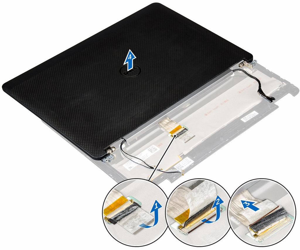
25 b. battery c. WLAN card d. WWAN card 3. To remove the display hinge brackets: a. Remove the screw that secures the display hinge bracket to the computer [1]. b. Remove the display hinge bracket from the computer [2]. 4. To disconnect the display assembly cable: a. Unroute the WLAN and WWAN cables from the routing channel on the system board [1]. b. Remove the screws that secure the display assembly cable bracket to the computer [2]. c. Remove the display assembly cable bracket to access the display assembly cable [3]. d. Disconnect the display assembly cable from the system board [4]. 5. To disconnect the display assembly: a. Remove the screws that secure the display assembly [1]. b. Release the WWAN and WLAN cables and display assembly cable from the slot on the computer [2]. 26
![6. To remove the display assembly: a. Remove the screws that secure the display assembly to the computer [1]. b.](/docs-images/74/71388857/images/26-0.jpg "Open the display assembly [2] and lift the display assembly to remove it from the computer [3]. Installing the display assembly 1. Insert the display hinges into the slots on the computer.")

26 6. To remove the display assembly: a. Remove the screws that secure the display assembly to the computer [1]. b. Open the display assembly [2] and lift the display assembly to remove it from the computer [3]. Installing the display assembly 1. Insert the display hinges into the slots on the computer. NOTE: This should be done with the display assembly in open position. Ensure that the cables are free from the hinge slots and computer. 2. Close the display assembly. 3. Insert the WLAN and WWAN cables through the slot on the computer 4. Route the display assembly cable through the slot and routing clips on the computer. 5. Tighten the screws to secure the display assembly to the computer. 6. Route the WLAN and WWAN cables through the routing channel on the system board. 7. Connect the WLAN and WWAN cables to the connectors on the WLAN and WWAN cards. 8. Connect the display cable to the connector on the system board. 9. Place the display cable bracket over the connector and tighten the screws to secure the display cable to the system board. 10. Tighten the screws to secure the display assembly to the computer. 11. Install the display hinge brackets and tighten the screws to secure it to the computer. 12. Install the: a. WLAN card b. WWAN card c. battery d. base cover 13. Follow the procedure in After working inside your computer. 27
27 Display bezel Removing the display bezel NOTE: The display bezel is available only for non touch systems. 1. Follow the procedure in Before working inside your computer. 2. Remove the: a. base cover b. battery c. display assembly 3. Using a plastic scribe, release the tabs on the edges to release the display bezel from the display assembly [1, 2]. 4. Remove the display bezel from the display assembly. Installing the display bezel 1. Place the display bezel on the display assembly. 2. Press the edges of the display bezel until it clicks onto the display assembly. 3. Install the: a. display assembly b. battery c. base cover 4. Follow the procedure in After working inside your system. Display panel Removing the display panel 1. Follow the procedure in Before working inside your computer. 2. Remove the: a. base cover b. battery c. display assembly 28

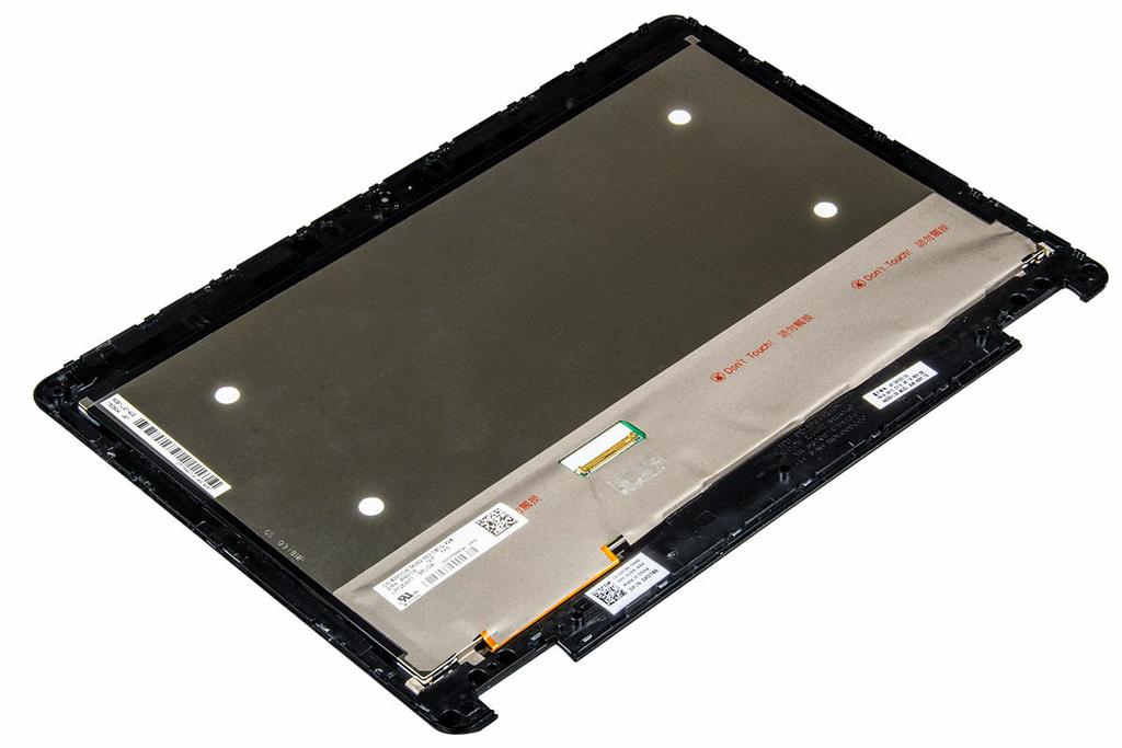
![ble [2]. c. Peel the adhesive [3] to access the edp cable. d. Disconnect the edp cable from the connector [4, 5, 6]. e. Lift the display panel. 4.](/docs-images/74/71388857/images/28-1.jpg "To remove the display panel for touch systems: a. Using a plastic scribe lift the edges of the display panel to disengage it from the display assembly. b.")
28 d. display bezel NOTE: This is applicable only for non touch systems. 3. To remove the display panel for non touch systems: a. Remove the screws that secure the display panel to the display assembly [1]. b. Lift the display panel and turn the display panel over to access the edp cable [2]. c. Peel the adhesive [3] to access the edp cable. d. Disconnect the edp cable from the connector [4, 5, 6]. e. Lift the display panel. 4. To remove the display panel for touch systems: a. Using a plastic scribe lift the edges of the display panel to disengage it from the display assembly. b. Place the display panel facedown. c. Slide the display assembly to access the edp cable. 29
29 30 d. Peel the adhesive to access the edp cable [1]. e. Disconnect the edp cable from the connector on the back of the display panel [2, 3]. f. Lift the display assembly from the display pane [4].
30 31
31 Installing the display panel 1. To install the display panel for non touch systems: a. Connect the edp cable to the connector on the back of the display panel and fix the adhesive tape. b. Align the display panel with the tabs on the display assembly. c. Tighten the screws to secure the display panel to the display assembly. 2. To install the display panel for touch systems: a. Place the display panel facedown. b. Place the display assembly over the display panel and slide it forward. c. Connect the edp cable to the connector on the back of the display panel and fix the adhesive tape. d. Turn the display assembly over. e. Align the display panel with the tabs on the display assembly. f. Press the edges of the display panel to secure it to the display assembly. 3. Install the: a. display bezel NOTE: This is applicable only for non touch systems. b. display assembly c. battery d. base cover 4. Follow the procedure in After working inside your system. Display hinges Removing the display hinge 1. Follow the procedure in Before working inside your computer. 2. Remove the: a. base cover b. battery c. display assembly d. display bezel e. display panel 3. To remove the hinges: NOTE: This is applicable only for non touch systems. NOTE: This is applicable only for touch systems. a. Remove the screws that secure the display hinge to the display assembly [1, 3]. NOTE: The number of screws will vary for touch and non touch systems. b. Remove the display hinge [2, 4]. 32


32 Figure 1. Removing hinges for a non touch system Figure 2. Removing hinges for a touch system Installing the display hinge 1. Align the display hinges with the screw holders on the display assembly. 2. Tighten the screws to secure the display hinge to the display assembly. 3. Install the: 33
33 a. display bezel b. display panel NOTE: This is applicable only for non touch systems. NOTE: This is applicable only for touch systems. c. display assembly d. battery e. base cover 4. Follow the procedure in After working inside your system. edp cable Removing the edp cable 1. Follow the procedure in Before working inside your computer. 2. Remove the: a. base cover b. battery c. display assembly d. display bezel e. display panel NOTE: This is applicable only for non touch systems. 3. Disconnect the camera cable from the camera [1]. 4. Peel the camera cable adhesive and unroute the edp and display cable from the routing clips on the display assembly [2, 3]. 5. Remove the edp cable from the display assembly. Figure 3. Removing the edp cable for non touch systems 34

34 Figure 4. Removing the edp cable for touch systems Installing the edp cable 1. Route the display cable through the routing clips on the display assembly. 2. Affix the camera cable adhesive and connect the camera cable. 3. Connect the edp cable to the connector on the display assembly. 4. Install the: a. display panel b. display bezel NOTE: This is applicable only for non touch systems. c. display assembly d. battery e. base cover 5. Follow the procedure in After working inside your system. Camera Removing the camera 1. Follow the procedure in Before working inside your computer. 2. Remove the: a. base cover b. battery c. display assembly d. display bezel NOTE: This is applicable only for non touch systems. 35

![Disconnect the camera cable from the connector on the display assembly [2]. 5.](/docs-images/74/71388857/images/35-1.jpg "Lift the camera away from the display assembly [3]. Figure 5.")
35 e. display panel 3. Peel the adhesive that secures the camera to the display assembly [1]. 4. Disconnect the camera cable from the connector on the display assembly [2]. 5. Lift the camera away from the display assembly [3]. Figure 5. Removing the camera from a non touch system Figure 6. Removing the camera from a touch system 36
36 Installing the camera 1. Place the camera on the display assembly. 2. Connect the camera cable to the connector on the display assembly 3. Affix the adhesive to secure the camera to the display assembly. 4. Install the: a. display panel b. display bezel NOTE: This is applicable only for non touch systems. c. display assembly d. battery e. base cover 5. Follow the procedure in After working inside your system. Palmrest Replacing the palmrest 1. Follow the procedure in Before working inside your computer. 2. Remove the: a. base cover b. battery c. memory module d. SSD e. dock frame f. WLAN card g. WWAN card h. heat sink assembly i. power connector port j. coin cell battery k. display assembly l. speakers m. keyboard n. system board NOTE: The component you are left with is the palmrest. 37
37 3. Install the following components on the new palmrest. a. keyboard assembly b. system board c. coin cell battery d. WLAN card e. WWAN card f. memory module g. heat sink assembly h. power connector port i. dock frame j. display assembly k. SSD l. speakers m. battery n. base cover 4. Follow the procedure in After working inside your system. 38
38 System Setup 3 Boot Sequence Boot Sequence allows you to bypass the System Setup defined boot device order and boot directly to a specific device (for example: optical drive or hard drive). During the Power-on Self Test (POST), when the Dell logo appears, you can: Access System Setup by pressing F2 key Bring up the one-time boot menu by pressing F12 key The one-time boot menu displays the devices that you can boot from including the diagnostic option. The boot menu options are: Removable Drive (if available) STXXXX Drive Optical Drive Diagnostics NOTE: XXX denotes the SATA drive number. NOTE: Choosing Diagnostics, will display the epsa diagnostics screen. The boot sequence screen also displays the option to access the System Setup screen. Navigation keys The following table displays the system setup navigation keys. NOTE: For most of the System Setup options, changes that you make are recorded but do not take effect until you restart the system. Table 1. Navigation keys Keys Up arrow Down arrow Enter Spacebar Tab Esc F1 Navigation Moves to the previous field. Moves to the next field. Allows you to select a value in the selected field (if applicable) or follow the link in the field. Expands or collapses a drop down list, if applicable. Moves to the next focus area. NOTE: For the standard graphics browser only. Moves to the previous page till you view the main screen. Pressing Esc in the main screen displays a message that prompts you to save any unsaved changes and restarts the system. Displays the System Setup help file. 39
39 System setup options NOTE: Depending on the computer and its installed devices, the items listed in this section may or may not appear. General screen options This section lists the primary hardware features of your computer. Option System Information Description This section lists the primary hardware features of your computer. System Information: Displays BIOS Version, Service Tag, Asset Tag, Ownership Tag, Ownership Date, Manufacture Date, and the Express Service Code. Memory Information: Displays Memory Installed, Memory Available, Memory Speed, Memory Channels Mode, Memory Technology, DIMM ASize, DIMM B Size, Processor Information: Displays Processor Type, Core Count, Processor ID, Current Clock Speed, Minimum Clock Speed, Maximum Clock Speed, Processor L2 Cache, Processor L3 Cache, HT Capable, and 64-Bit Technology. Device Information: Displays Primary Hard Drive, M.2 SSD-0, Dock esata Device, LOM MAC Address, Video Controller, Video BIOS Version, Video Memory, Panel Type, Native Resolution, Audio Controller, Wi-Fi Device, WiGig Device, Cellular Device, Bluetooth Device. Battery Information Boot Sequence Displays the battery status and the type of AC adapter connected to the computer. Allows you to change the order in which the computer attempts to find an operating system. Diskette Drive Internal HDD USB Storage Device CD/DVD/CD-RW Drive Onboard NIC Advanced Boot Options Date/Time This option allows you the legacy option ROMs to load. By default, the Enable Legacy Option ROMs is disabled. Allows you to change the date and time. System Configuration screen options Option Integrated NIC Description Allows you to configure the integrated network controller. The options are: Disabled Enabled Enabled w/pxe: This option is enabled by default. Parallel Port Allows you to configure the parallel port on the docking station. The options are: Disabled AT: This option is enabled by default. PS2 40
40 Option Serial Port Description ECP Allows you to configure the integrated serial port. The options are: Disabled COM1: This option is enabled by default. COM2 COM3 COM4 SATA Operation Allows you to configure the internal SATA hard-drive controller. The options are: Disabled AHCI RAID On: This option is enabled by default. Drives Allows you to configure the SATA drives on board. All drives are enabled by default. The options are: SATA-1 M.2 PCI-e SSD-0 SATA-2 SMART Reporting This field controls whether hard drive errors for integrated drives are reported during system startup. This technology is part of the SMART (Self Monitoring Analysis and Reporting Technology) specification. This option is disabled by default. Enable SMART Reporting USB Configuration This is an optional feature. This field configures the integrated USB controller. If Boot Support is enabled, the system is allowed to boot any type of USB Mass Storage Devices (HDD, memory key, floppy). If USB port is enabled, device attached to this port is enabled and available for OS. If USB port is disabled, the OS cannot see any device attached to this port. The options are: Enable USB Boot Support (by default enable) Enable External USB Port (by default enable) NOTE: USB keyboard and mouse always work in the BIOS setup irrespective of these settings. USB PowerShare Audio This field configures the USB PowerShare feature behavior. This option allows you to charge external devices using the stored system battery power through the USB PowerShare port. This field enables or disables the integrated audio controller. By default, the Enable Audio option is selected. The options are: Enable Microphone (by default enable) Enable Internal Speaker (by default enable) 41
41 Option Keyboard Illumination Description This field lets you choose the operating mode of the keyboard illumination feature. The keyboard brightness level can be set from 0% to 100%. The options are: Disabled Dim Bright (enabled by default) Keyboard Backlight with AC Keyboard Backlight Timeout with AC Keyboard Backlight Timeout on Battery Unobtrusive Mode Miscellaneous Devices The Keyboard Backlight with AC option does not affect the main keyboard illumination feature. Keyboard Illumination will continue to support the various illumination levels. This field has an effect when the backlight is enabled. The Keyboard Backlight Timeout dims out with AC option. The main keyboard illumination feature is not affected. Keyboard Illumination will continue to support the various illumination levels. This field has an effect when the backlight is enabled. The Keyboard Backlight Timeout dims out with Battery option. The main keyboard illumination feature is not affected. Keyboard Illumination will continue to support the various illumination levels. This field has an effect when the backlight is enabled. This option, when enabled, pressing Fn+F7 turns off all light and sound emissions in the system. To resume normal operation, press Fn+F7 again. This option is disabled by default. Allows you to enable or disable the following devices: Enable Camera enabled by default SD Card Read Only enabled by default Enable Media Card Disable Media Card Video screen options Option LCD Brightness Description Allows you to set the display brightness depending up on the power source (On Battery and On AC). NOTE: The video setting will be visible only when a video card is installed into the system. Security screen options Option Admin Password Description Allows you to set, change, or delete the administrator (admin) password. NOTE: You must set the admin password before you set the system or hard drive password. Deleting the admin password automatically deletes the system password and the hard drive password. NOTE: Successful password changes take effect immediately. Default setting: Not set System Password Allows you to set, change or delete the system password. NOTE: Successful password changes take effect immediately. 42
42 Option Description Default setting: Not set Internal HDD-2 Password Allows you to set, change, or delete the administrator password. NOTE: Successful password changes take effect immediately. Default setting: Not set Strong Password Allows you to enforce the option to always set strong passwords. Default Setting: Enable Strong Password is not selected. NOTE: If Strong Password is enabled, Admin and System passwords must contain at least one uppercase character, one lowercase character and be at least 8 characters long. Password Configuration Password Bypass Allows you to determine the minimum and maximum length of Administrator and System passwords. Allows you to enable or disable the permission to bypass the System and the Internal HDD password, when they are set. The options are: Disabled Reboot bypass Default setting: Disabled Password Change Allows you to enable the disable permission to the System and Hard Drive passwords when the admin password is set. Default setting: Allow Non-Admin Password Changes is selected. Non-Admin Setup Changes TPM 1.2/2.0 Security Allows you to determine whether changes to the setup options are allowed when an Administrator Password is set. If disabled the setup options are locked by the admin password. Allows you to enable the Trusted Platform Module (TPM) during POST. The options are: TPM On (enabled by default) Clear PPI Bypass for Enabled Commands PPI Bypass for Disabled Commands Disabled Enabled NOTE: To upgrade or downgrade TPM1.2/2.0, download the TPM wrapper tool (software). Computrace Allows you to activate or disable the optional Computrace software The options are: Deactivate Disable Activate NOTE: The Activate and Disable options will permanently activate or disable the feature and no further changes will be allowed Default setting: Deactivate 43
43 Option CPU XD Support Description Allows you to enable the Execute Disable mode of the processor. Enable CPU XD Support (default) OROM Keyboard Access Allows you to set an option to enter the Option ROM Configuration screens using hotkeys during boot. The options are: Enable One Time Enable Disable Default setting: Enable Admin Setup Lockout Allows you to prevent users from entering Setup when an Administrator password is set. Default Setting: Disabled Secure Boot screen options Option Secure Boot Enable Description This option enables or disables the Secure Boot feature. Disabled Enabled Default setting: Enabled. Intel Software Guard Extensions This fields specifies you to provide a secured environment for running code/storing sensitive information in the context of the main OS. The options are: Disabled (Default Setting) Enabled Enclave Memory Size: Intel Software Guard Extensions This option sets SGX Enclave Reserve Memory Size. The option are: 32 MB 64 MB 128 MB This fields specifies you to provide a secured environment for running code/storing sensitive information in the context of the main OS. The options are: Disabled (Default Setting) Enabled Enclave Memory Size: This option sets SGX Enclave Reserve Memory Size. The option are: 32 MB 64 MB 128 MB 44
44 Option Expert Key Management Description Allows you to manipulate the security key databases only if the system is in Custom Mode. The Enable Custom Mode option is disabled by default. The options are: PK KEK db dbx If you enable the Custom Mode, the relevant options for PK, KEK, db, and dbx appear. The options are: Save to File Saves the key to a user-selected file Replace from File Replaces the current key with a key from a user-selected file Append from File Adds a key to the current database from a user-selected file Delete Deletes the selected key Reset All Keys Resets to default setting Delete All Keys Deletes all the keys NOTE: If you disable the Custom Mode, all the changes made will be erased and the keys will restore to default settings. Intel Software Guard Extensions This fields specifies you to provide a secured environment for running code/storing sensitive information in the context of the main OS. The options are: Disabled (Default Setting) Enabled Enclave Memory Size This option sets SGX Enclave Reserve Memory Size. The option are: 32 MB 64 MB 128 MB Intel Software Guard Extensions screen options Option Intel SGX Enable Description This field specifies you to provide a secured environment for running code/storing sensitive information in the context of the main OS. The options are: Disabled Enabled Default setting: Disabled Enclave Memory Size This option sets SGX Enclave Reserve Memory Size. The options are: 32 MB 64 MB 128 MB 45
45 Performance screen options Option Multi Core Support Description This field specifies whether the process has one or all cores enabled. The performance of some applications improves with the additional cores. This option is enabled by default. Allows you to enable or disable multicore support for the processor. The installed processor supports two cores. If you enable Multi Core Support, two cores are enabled. If you disable Multi Core Support, one core is enabled. Enable Multi Core Support Default setting: The option is enabled. Intel SpeedStep Allows you to enable or disable the Intel SpeedStep feature. Enable Intel SpeedStep Default setting: The option is enabled. C-States Control Allows you to enable or disable the additional processor sleep states. C states Default setting: The option is enabled. Intel TurboBoost Allows you to enable or disable the Intel TurboBoost mode of the processor. Enable Intel TurboBoost Default setting: The option is enabled. Hyper-Thread Control Allows you to enable or disable the Hyper-Threading in the processor. Disabled Enabled Default setting: Enabled. Power Management screen options Option AC Behavior Description Allows you to enable or disable the computer from turning on automatically when an AC adapter is connected. Default setting: Wake on AC is not selected. Auto On Time Allows you to set the time at which the computer must turn on automatically. The options are: Disabled Every Day Weekdays Select Days 46
46 Option Description Default setting: Disabled USB Wake Support Allows you to enable USB devices to wake the system from Standby. NOTE: This feature is only functional when the AC power adapter is connected. If the AC power adapter is removed during Standby, the system setup removes power from all the USB ports to conserve battery power. Enable USB Wake Support Default setting: The option is disabled. Wireless Radio Control Allows you to enable or disable the feature that automatically switches from wired or wireless networks without depending on the physical connection. Control WLAN Radio Control WWAN Radio Default setting: The option is disabled. Wake on LAN/ WLAN Allows you to enable or disable the feature that powers on the computer from the Off state when triggered by a LAN signal. Disabled LAN Only WLAN Only LAN or WLAN Default setting: Disabled Block Sleep This option lets you block entering to sleep (S3 state) in operating system environment. Block Sleep (S3 state) Default setting: This option is disabled Peak Shift Dock Support on Battery This option enables you to minimize the AC power consumption during the peak power times of day. After you enable this option, your system runs only in battery even if the AC is attached. This option allows you to use the docking station when AC power is absent but only when the battery is above a certain charge percentage. The percentage may change per battery and per platform. Dock Support on Battery Default setting: Disabled Advanced Battery Charge Configuration This option enables you to maximize the battery health. By enabling this option, your system uses the standard charging algorithm and other techniques, during the non-work hours to improve the battery health. Disabled Default setting: Disabled 47
47 Option Primary Battery Charge Configuration Description Allows you to select the charging mode for the battery. The options are: Adaptive Standard Fully charges your battery at a standard rate. ExpressCharge The battery charges over a shorter period of time using Dell s fast charging technology. This option is enabled by default. Primarily AC use Custom If Custom Charge is selected, you can also configure Custom Charge Start and Custom Charge Stop. NOTE: All charging mode may not be available for all the batteries. To enable this option, disable the Advanced Battery Charge Configuration option. POST Behavior screen options Option Adapter Warnings Description Allows you to enable or disable the system setup (BIOS) warning messages when you use certain power adapters. Default setting: Enable Adapter Warnings Keypad (Embedded) Allows you to choose one of two methods to enable the keypad that is embedded in the internal keyboard. Fn Key Only: This option is enabled by default. By Numlock NOTE: When setup is running, this option has no effect. Setup works in Fn Key Only mode. Mouse/Touchpad Allows you to define how the system handles mouse and touch pad input. The options are: Serial Mouse PS2 Mouse Touchpad/PS-2 Mouse: This option is enabled by default. Numlock Enable Allows you to enable the Numlock option when the computer boots. Enable Network. This option is enabled by default. Fn Key Emulation Allows you to set the option where the Scroll Lock key is used to simulate the Fn key feature. Enable Fn Key Emulation (default) Fn Lock Options Allows you to let hot key combinations Fn + Esc toggle the primary behavior of F1 F12, between their standard and secondary functions. If you disable this option, you cannot toggle dynamically the primary behavior of these keys. The available options are: Fn Lock. This option is selected by default. Lock Mode Disable/Standard Lock Mode Enable/Secondary MEBx Hotkey Allows you to specify whether the MEBx Hotkey function should enable, during the system boot. 48
48 Option Description Default Setting: Enable MEBx Hotkey Fastboot Allows you to speed up the boot process by bypassing some of the compatibility steps. The options are: Minimal Thorough (default) Auto Extended BIOS POST Time Allows you to create an additional preboot delay. The options are: 0 seconds. This option is enabled by default. 5 seconds 10 seconds Virtualization support screen options Option Virtualization Description Allows you to enable or disable the Intel Virtualization Technology. Enable Intel Virtualization Technology (default). VT for Direct I/O Enables or disables the Virtual Machine Monitor (VMM) from utilizing the additional hardware capabilities provided by Intel Virtualization technology for direct I/O. Enable VT for Direct I/O - enabled by default. Trusted Execution This option specifies whether a Measured Virtual Machine Monitor (MVMM) can utilize the additional hardware capabilities provided by Intel Trusted Execution Technology. The TPM Virtualization Technology, and Virtualization technology for direct I/O must be enabled to use this feature. Trusted Execution - disabled by default. Wireless screen options Option Wireless Switch Description Allows to set the wireless devices that can be controlled by the wireless switch. The options are: WWAN GPS (on WWAN Module) WLAN/WiGig Bluetooth All the options are enabled by default. NOTE: For WLAN and WiGig enable or disable controls are tied together and they cannot be enabled or disabled independently. Wireless Device Enable Allows you to enable or disable the internal wireless devices. WWAN/GPS 49
49 Option Description WLAN/WiGig Bluetooth All the options are enabled by default. Maintenance screen options Option Service Tag Asset Tag BIOS Downgrade Data Wipe Description Displays the Service Tag of your computer. Allows you to create a system asset tag if an asset tag is not already set. This option is not set by default. This controls flashing of the system firmware to previous revisions. This field allows users to erase the data securely from all internal storage devices. The following is list of devices affected: Internal HDD Internal SDD Internal msata Internal emmc BIOS Recovery This field allows you to recover from certain corrupted BIOS conditions from a recover file on the user primary hard drive or an external USB key. BIOS Recovery from Hard Drive (enabled by default) System Log screen options Option BIOS Events Thermal Events Power Events Description Allows you to view and clear the System Setup (BIOS) POST events. Allows you to view and clear the System Setup (Thermal) events. Allows you to view and clear the System Setup (Power) events. Updating the BIOS It is recommended to update your BIOS (System Setup), on replacing the system board or if an update is available. For laptops, ensure that your computer battery is fully charged and connected to a power outlet 1. Restart the computer. 3. Enter the Service Tag or Express Service Code and click Submit. NOTE: To locate the Service Tag, click Where is my Service Tag? NOTE: If you cannot find your Service Tag, click Detect My Product. Proceed with the instructions on screen. 4. If you are unable to locate or find the Service Tag, click the Product Category of your computer. 5. Choose the Product Type from the list. 6. Select your computer model and the Product Support page of your computer appears. 50
Dell Latitude E7270 Owner's Manual
 Dell Latitude E7270 Owner's Manual Regulatory Model: P26S Regulatory Type: P26S001 Notes, cautions, and warnings NOTE: A NOTE indicates important information that helps you make better use of your computer.
Dell Latitude E7270 Owner's Manual
 Dell Latitude E7270 Owner's Manual Regulatory Model: P26S Regulatory Type: P26S001 Notes, cautions, and warnings NOTE: A NOTE indicates important information that helps you make better use of your computer.
Dell Latitude E5470 Owner's Manual
 Dell Latitude E5470 Owner's Manual Regulatory Model: P62G Regulatory Type: P62G001 Notes, cautions, and warnings NOTE: A NOTE indicates important information that helps you make better use of your computer.
Dell Latitude E5570 Owner's Manual
 Dell Latitude E5570 Owner's Manual Regulatory Model: P48F Regulatory Type: P48F001 Notes, cautions, and warnings NOTE: A NOTE indicates important information that helps you make better use of your computer.
Dell Precision 3510 Owner's Manual
 Dell Precision 3510 Owner's Manual Regulatory Model: P48F Regulatory Type: P48F001 Notes, cautions, and warnings NOTE: A NOTE indicates important information that helps you make better use of your computer.
Dell Latitude Owner's Manual. Regulatory Model: P73G Regulatory Type: P73G001
 Dell Latitude 7480 Owner's Manual Regulatory Model: P73G Regulatory Type: P73G001 Notes, cautions, and warnings NOTE: A NOTE indicates important information that helps you make better use of your product.
Dell Latitude E5470. Owner's Manual. Regulatory Model: P62G Regulatory Type: P62G001
 Dell Latitude E5470 Owner's Manual Regulatory Model: P62G Regulatory Type: P62G001 Notes, cautions, and warnings NOTE: A NOTE indicates important information that helps you make better use of your product.
Dell Latitude 3560 Owner's Manual
 Dell Latitude 3560 Owner's Manual Regulatory Model: P50F Regulatory Type: P50F001 Notes, cautions, and warnings NOTE: A NOTE indicates important information that helps you make better use of your computer.
Dell Latitude E5540 Owner's Manual
 Dell Latitude E5540 Owner's Manual Regulatory Model: P44G Regulatory Type: P44G001 Notes, Cautions, and Warnings NOTE: A NOTE indicates important information that helps you make better use of your computer.
Dell Latitude Owner's Manual. Regulatory Model: P73G Regulatory Type: P73G001
 Dell Latitude 7480 Owner's Manual Regulatory Model: P73G Regulatory Type: P73G001 Notes, cautions, and warnings NOTE: A NOTE indicates important information that helps you make better use of your product.
Dell Precision series (7710)
") Dell Precision 17 7000 series (7710) Owner's Manual Regulatory Model: P29E Regulatory Type: P29E001 2016 Dell Inc. All rights reserved. This product is protected by U.S. and international copyright and
Dell Precision 17 7000 series (7710) Owner's Manual Regulatory Model: P29E Regulatory Type: P29E001 2016 Dell Inc. All rights reserved. This product is protected by U.S. and international copyright and
Dell Latitude Owner's Manual. Regulatory Model: P63G Regulatory Type: P63G001
 Dell Latitude 3460 Owner's Manual Regulatory Model: P63G Regulatory Type: P63G001 Notes, cautions, and warnings NOTE: A NOTE indicates important information that helps you make better use of your computer.
Dell Latitude Owner's Manual. Regulatory Model: P63G Regulatory Type: P63G001
 Dell Latitude 3470 Owner's Manual Regulatory Model: P63G Regulatory Type: P63G001 Notes, cautions, and warnings NOTE: A NOTE indicates important information that helps you make better use of your computer.
Dell Precision M2800 Owner's Manual
 Dell Precision M2800 Owner's Manual Regulatory Model: P29F Regulatory Type: P29F001 Notes, Cautions, and Warnings NOTE: A NOTE indicates important information that helps you make better use of your computer.
Dell Precision series (7710) Owner's Manual
 Owner's Manual") Dell Precision 17 7000 series (7710) Owner's Manual Regulatory Model: P29E Regulatory Type: P29E001 2016 Dell Inc. All rights reserved. This product is protected by U.S. and international copyright and
Dell Precision 17 7000 series (7710) Owner's Manual Regulatory Model: P29E Regulatory Type: P29E001 2016 Dell Inc. All rights reserved. This product is protected by U.S. and international copyright and
Dell Latitude 3460 Owner's Manual
 Dell Latitude 3460 Owner's Manual Regulatory Model: P63G Regulatory Type: P63G001 Notes, cautions, and warnings NOTE: A NOTE indicates important information that helps you make better use of your computer.
Dell Precision series (7510) Owner's Manual
 Owner's Manual") Dell Precision 15 7000 series (7510) Owner's Manual Regulatory Model: P53F Regulatory Type: P53F001 Copyright 20152016 Dell Inc. or its subsidiaries. All rights reserved. This product is protected by U.S.
Dell Precision 15 7000 series (7510) Owner's Manual Regulatory Model: P53F Regulatory Type: P53F001 Copyright 20152016 Dell Inc. or its subsidiaries. All rights reserved. This product is protected by U.S.
Dell Latitude Owner's Manual. Regulatory Model: P73G Regulatory Type: P73G001
 Dell Latitude 7480 Owner's Manual Regulatory Model: P73G Regulatory Type: P73G001 Notes, cautions, and warnings NOTE: A NOTE indicates important information that helps you make better use of your product.
Dell Latitude 3550 Owner's Manual
 Dell Latitude 3550 Owner's Manual Regulatory Model: P38F Regulatory Type: P38F001 Notes, cautions, and warnings NOTE: A NOTE indicates important information that helps you make better use of your computer.
Dell Precision Mobile Workstation M6800 Owner's Manual
 Dell Precision Mobile Workstation M6800 Owner's Manual Regulatory Model: P30F Regulatory Type: P30F001 Copyright 2015 Dell Inc. All rights reserved. This product is protected by U.S. and international
Dell Latitude E7240 Owner's Manual
 Dell Latitude E7240 Owner's Manual Regulatory Model: P22S Regulatory Type: P22S001 Notes, Cautions, and Warnings NOTE: A NOTE indicates important information that helps you make better use of your computer.
Dell Latitude E7450 Owner's Manual
 Dell Latitude E7450 Owner's Manual Regulatory Model: P40G Regulatory Type: P40G002 Notes, Cautions, and Warnings NOTE: A NOTE indicates important information that helps you make better use of your computer.
Dell OptiPlex 7440 All-In-One Owner's Manual
 Dell OptiPlex 7440 All-In-One Owner's Manual Regulatory Model: W11C Regulatory Type: W11C001 Notes, cautions, and warnings NOTE: A NOTE indicates important information that helps you make better use of
Dell Latitude E5540 Owner's Manual
 Dell Latitude E5540 Owner's Manual Regulatory Model: P44G Regulatory Type: P44G001 Notes, Cautions, and Warnings NOTE: A NOTE indicates important information that helps you make better use of your computer.
Dell Latitude E6430 / E6430 ATG Owner's Manual
 Dell Latitude E6430 / E6430 ATG Owner's Manual Regulatory Model: P25G Regulatory Type: P25G001, P25G002 Notes, Cautions, and Warnings NOTE: A NOTE indicates important information that helps you make better
Dell OptiPlex 7440 All-In-One Owner's Manual
 Dell OptiPlex 7440 All-In-One Owner's Manual Regulatory Model: W11C Regulatory Type: W11C001 Notes, cautions, and warnings NOTE: A NOTE indicates important information that helps you make better use of
Dell Latitude E5250 / 5250 Owner's Manual
 Dell Latitude E5250 / 5250 Owner's Manual Regulatory Model: P25S Regulatory Type: P25S001 Notes, Cautions, and Warnings NOTE: A NOTE indicates important information that helps you make better use of your
Dell Latitude E5440 Owner's Manual
 Dell Latitude E5440 Owner's Manual Regulatory Model: P44G Regulatory Type: P44G001 Notes, Cautions, and Warnings NOTE: A NOTE indicates important information that helps you make better use of your computer.
Dell OptiPlex 9020 AIO Owner's Manual
 Dell OptiPlex 9020 AIO Owner's Manual Regulatory Model: W04C Regulatory Type: W04C002 Notes, Cautions, and Warnings NOTE: A NOTE indicates important information that helps you make better use of your computer.
Dell OptiPlex 3240 All-In-One Owner's Manual
 Dell OptiPlex 3240 All-In-One Owner's Manual Regulatory Model: W14B Regulatory Type: W14B001 Notes, cautions, and warnings NOTE: A NOTE indicates important information that helps you make better use of
Dell Latitude 14 Rugged Extreme 7404 Owner's Manual
 Dell Latitude 14 Rugged Extreme 7404 Owner's Manual Regulatory Model: P45G Regulatory Type: P45G001 Notes, Cautions, and Warnings NOTE: A NOTE indicates important information that helps you make better
Dell Latitude 3450 Owner's Manual
 Dell Latitude 3450 Owner's Manual Regulatory Model: P51G Regulatory Type: P51G001 Notes, Cautions, and Warnings NOTE: A NOTE indicates important information that helps you make better use of your computer.
Dell Latitude E7240 Owner's Manual
 Dell Latitude E7240 Owner's Manual Regulatory Model: P22S Regulatory Type: P22S001 Notes, Cautions, and Warnings NOTE: A NOTE indicates important information that helps you make better use of your computer.
Dell Latitude E6540 Owner's Manual
 Dell Latitude E6540 Owner's Manual Regulatory Model: P29F Regulatory Type: P29F001 Notes, Cautions, and Warnings NOTE: A NOTE indicates important information that helps you make better use of your computer.
The Dell Precision M6500 system setup can be navigated by keyboard or mouse / touchpad. Navigation Keystrokes
 System BIOS The Precision M6500 system offers you the following options: Access System Setup by pressing Bring up a one-time boot menu by pressing System Setup Press to enter System Setup
Dell Precision Workstation T7610 Owner's Manual
 Dell Precision Workstation T7610 Owner's Manual Regulatory Model: D02X Regulatory Type: D02X002 Notes, Cautions, and Warnings NOTE: A NOTE indicates important information that helps you make better use
Dell Latitude E6230 Owner's Manual
 Dell Latitude E6230 Owner's Manual Regulatory Model: P14T Regulatory Type: P14T001 Notes, Cautions, and Warnings NOTE: A NOTE indicates important information that helps you make better use of your computer.
Dell Latitude 3450 Owner's Manual
 Dell Latitude 3450 Owner's Manual Regulatory Model: P51G Regulatory Type: P51G001 Notes, cautions, and warnings NOTE: A NOTE indicates important information that helps you make better use of your product.
Dell OptiPlex 9030 All-In-One Owner's Manual
 Dell OptiPlex 9030 All-In-One Owner's Manual Regulatory Model: W09C Regulatory Type: W09C001 Notes, cautions, and warnings NOTE: A NOTE indicates important information that helps you make better use of
Dell Precision Owner's Manual. Regulatory Model: P60F Regulatory Type: P60F001
 Dell Precision 3520 Owner's Manual Regulatory Model: P60F Regulatory Type: P60F001 Notes, cautions, and warnings NOTE: A NOTE indicates important information that helps you make better use of your product.
Dell Latitude Owner's Manual. Regulatory Model: P28S Regulatory Type: P28S001
 Dell Latitude 7280 Owner's Manual Regulatory Model: P28S Regulatory Type: P28S001 Notes, cautions, and warnings NOTE: A NOTE indicates important information that helps you make better use of your product.
Vostro Owner's Manual
 Vostro 14-5459 Owner's Manual Regulatory Model: P68G Regulatory Type: P68G001 Copyright 2015 Dell Inc. All rights reserved. This product is protected by U.S. and international copyright and intellectual
Dell Latitude 6430u Owner's Manual
 Dell Latitude 6430u Owner's Manual Regulatory Model: P36G Regulatory Type: P36G001 Notes, Cautions, and Warnings NOTE: A NOTE indicates important information that helps you make better use of your computer.
Dell Latitude 14 Rugged 5414
 Dell Latitude 14 Rugged 5414 Owner's Manual Regulatory Model: P46G Regulatory Type: P46G002 Notes, cautions, and warnings NOTE: A NOTE indicates important information that helps you make better use of
Dell Latitude Owner's Manual. Regulatory Model: P27S Regulatory Type: P27S001
 Dell Latitude 5280 Owner's Manual Regulatory Model: P27S Regulatory Type: P27S001 Notes, cautions, and warnings NOTE: A NOTE indicates important information that helps you make better use of your product.
Dell Latitude 3160 Owner's Manual
 Dell Latitude 3160 Owner's Manual Regulatory Model: P21T Regulatory Type: P21T002 Notes, cautions, and warnings NOTE: A NOTE indicates important information that helps you make better use of your computer.
Dell Vostro Owner's Manual
 Dell Vostro 15 3559 Owner's Manual Regulatory Model: P52F Regulatory Type: P52F003 Notes, cautions, and warnings NOTE: A NOTE indicates important information that helps you make better use of your computer.
Dell Latitude Owner's Manual. Regulatory Model: P60F Regulatory Type: P60F001
 Dell Latitude 5580 Owner's Manual Regulatory Model: P60F Regulatory Type: P60F001 Notes, cautions, and warnings NOTE: A NOTE indicates important information that helps you make better use of your product.
Dell Precision Tower 7910 Owner's Manual
 Dell Precision Tower 7910 Owner's Manual Regulatory Model: D02X Regulatory Type: D02X003 Notes, cautions, and warnings NOTE: A NOTE indicates important information that helps you make better use of your
Dell OptiPlex 9020M Owner's Manual
 Dell OptiPlex 9020M Owner's Manual Regulatory Model: D09U Regulatory Type: D09U001 Notes, Cautions, and Warnings NOTE: A NOTE indicates important information that helps you make better use of your computer.
Dell XPS L702X Service Manual
 Dell XPS L702X Service Manual Regulatory model: P09E series Regulatory type: P09E002 Notes, Cautions, and Warnings NOTE: A NOTE indicates important information that helps you make better use of your computer.
Inspiron Service Manual. 2-in-1. Computer Model: Inspiron Regulatory Model: P69G Regulatory Type: P69G001
 Inspiron 13 5000 2-in-1 Service Manual Computer Model: Inspiron 13-5378 Regulatory Model: P69G Regulatory Type: P69G001 Notes, cautions, and warnings NOTE: A NOTE indicates important information that helps
Dell OptiPlex 9020 AIO Owner's Manual
 Dell OptiPlex 9020 AIO Owner's Manual Regulatory Model: W04C Regulatory Type: W04C002 Notes, Cautions, and Warnings NOTE: A NOTE indicates important information that helps you make better use of your computer.
Inspiron 22. Service Manual Series. Regulatory Model: W17B Regulatory Type: W17B001
 Inspiron 22 3000 Series Service Manual Regulatory Model: W17B Regulatory Type: W17B001 Notes, cautions, and warnings NOTE: A NOTE indicates important information that helps you make better use of your
Dell XPS 14z Owner s Manual
 Dell XPS 14z Owner s Manual Computer model: L412z Regulatory model: P24G series Regulatory type: P24G001 Notes, Cautions, and Warnings NOTE: A NOTE indicates important information that helps you make better
Dell Latitude 3350 Owner's Manual
 Dell Latitude 3350 Owner's Manual Regulatory Model: P47G Regulatory Type: P47G002 Notes, cautions, and warnings NOTE: A NOTE indicates important information that helps you make better use of your computer.
XPS 15 2-in-1. Service Manual. Computer Model: XPS Regulatory Model: P73F Regulatory Type: P73F001
 XPS 15 2-in-1 Service Manual Computer Model: XPS 15-9575 Regulatory Model: P73F Regulatory Type: P73F001 Notes, cautions, and warnings NOTE: A NOTE indicates important information that helps you make better
Dell OptiPlex 9020 Small Form Factor Owner's Manual
 Dell OptiPlex 9020 Small Form Factor Owner's Manual Regulatory Model: D07S Regulatory Type: D07S001 Notes, cautions, and warnings NOTE: A NOTE indicates important information that helps you make better
Dell Latitude Owner's Manual. Regulatory Model: P60F Regulatory Type: P60F001
 Dell Latitude 5580 Owner's Manual Regulatory Model: P60F Regulatory Type: P60F001 Notes, cautions, and warnings NOTE: A NOTE indicates important information that helps you make better use of your product.
OptiPlex Mini Tower
 OptiPlex 3046 - Mini Tower Owner's Manual Regulatory Model: D18M Regulatory Type: D18M002 Notes, cautions, and warnings NOTE: A NOTE indicates important information that helps you make better use of your
OptiPlex Mini Tower Owner's Manual
 OptiPlex 7040 - Mini Tower Owner's Manual Regulatory Model: D18M Regulatory Type: D18M001 Notes, cautions, and warnings NOTE: A NOTE indicates important information that helps you make better use of your
Dell Precision Tower 3620 Owner's Manual
 Dell Precision Tower 3620 Owner's Manual Regulatory Model: D13M Regulatory Type: D13M002 Notes, cautions, and warnings NOTE: A NOTE indicates important information that helps you make better use of your
Dell Inspiron N5110 Service Manual
 Dell Inspiron N5110 Service Manual Regulatory model: P17F Regulatory type: P17F001 Notes, Cautions, and Warnings NOTE: A NOTE indicates important information that helps you make better use of your computer.
Dell Vostro 5480 Owner's Manual
 Dell Vostro 5480 Owner's Manual Regulatory Model: P41G Regulatory Type: P41G002 Notes, Cautions, and Warnings NOTE: A NOTE indicates important information that helps you make better use of your computer.
Dell Precision Owner's Manual. Regulatory Model: P60F Regulatory Type: P60F001
 Dell Precision 3520 Owner's Manual Regulatory Model: P60F Regulatory Type: P60F001 Notes, cautions, and warnings NOTE: A NOTE indicates important information that helps you make better use of your product.
Dell Precision Tower 3420
 Dell Precision Tower 3420 Owner's Manual Regulatory Model: D11S Regulatory Type: D11S001 Notes, cautions, and warnings NOTE: A NOTE indicates important information that helps you make better use of your
Dell Precision Tower 7810 Owner's Manual
 Dell Precision Tower 7810 Owner's Manual Regulatory Model: D01T Regulatory Type: D01T005 Notes, cautions, and warnings NOTE: A NOTE indicates important information that helps you make better use of your
Dell Vostro Owner's Manual
 Dell Vostro 15 3549 Owner's Manual Regulatory Model: P45F Regulatory Type: P45F001 Notes, Cautions, and Warnings NOTE: A NOTE indicates important information that helps you make better use of your computer.
Dell OptiPlex 9010/7010 Mini-Tower Owner's Manual
 Dell OptiPlex 9010/7010 Mini-Tower Owner's Manual Regulatory Model: D09M Regulatory Type: D09M003 Notes, Cautions, and Warnings NOTE: A NOTE indicates important information that helps you make better use
Dell Precision Tower 5810 Owner's Manual
 Dell Precision Tower 5810 Owner's Manual Regulatory Model: D01T Regulatory Type: D01T006 Notes, cautions, and warnings NOTE: A NOTE indicates important information that helps you make better use of your
Dell PowerEdge T20 Owner's Manual
 Dell PowerEdge T20 Owner's Manual Regulatory Model: D13M Regulatory Type: D13M001 Notes, Cautions, and Warnings NOTE: A NOTE indicates important information that helps you make better use of your computer.
Dell Latitude Owner's Manual. Regulatory Model: P60F Regulatory Type: P60F001
 Dell Latitude 5580 Owner's Manual Regulatory Model: P60F Regulatory Type: P60F001 Notes, cautions, and warnings NOTE: A NOTE indicates important information that helps you make better use of your product.
Dell Vostro Owner's Manual
 Dell Vostro 20 3052 Owner's Manual Regulatory Model: W15B Regulatory Type: W15B002 Notes, cautions, and warnings NOTE: A NOTE indicates important information that helps you make better use of your computer.
OptiPlex Small Form Factor Owner's Manual
 OptiPlex 7040 - Small Form Factor Owner's Manual Regulatory Model: D11S Regulatory Type: D11S001 Notes, cautions, and warnings NOTE: A NOTE indicates important information that helps you make better use
Dell OptiPlex 9010/7010 Small Form Factor Owner's Manual
 Dell OptiPlex 9010/7010 Small Form Factor Owner's Manual Regulatory Model: D03S Regulatory Type: D03S002 Notes, Cautions, and Warnings NOTE: A NOTE indicates important information that helps you make better
OptiPlex 3050 Micro. Owner's Manual. Regulatory Model: D10U Regulatory Type: D10U002
 OptiPlex 3050 Micro Owner's Manual Regulatory Model: D10U Regulatory Type: D10U002 Notes, cautions, and warnings NOTE: A NOTE indicates important information that helps you make better use of your product.
Dell Precision Workstation T5600 Owner's Manual
 Dell Precision Workstation T5600 Owner's Manual Regulatory Model: D01T Regulatory Type: D01T001 Notes, cautions, and warnings NOTE: A NOTE indicates important information that helps you make better use
Vostro Owner's Manual. Regulatory Model: P75G Regulatory Type: P75G001
 Vostro 14-5468 Owner's Manual Regulatory Model: P75G Regulatory Type: P75G001 2016 2018 Dell Inc. or its subsidiaries. All rights reserved. Dell, EMC, and other trademarks are trademarks of Dell Inc. or
OptiPlex Small Form Factor Owner's Manual
 OptiPlex 7040 - Small Form Factor Owner's Manual Regulatory Model: D11S Regulatory Type: D11S001 Notes, cautions, and warnings NOTE: A NOTE indicates important information that helps you make better use
XPS 13 Convertible Service Manual
 XPS 13 Convertible Service Manual Computer Model: XPS 9365 Regulatory Model: P71G Regulatory Type: P71G001 Notes, cautions, and warnings NOTE: A NOTE indicates important information that helps you make
Dell Precision Tower 5810 Owner's Manual
 Dell Precision Tower 5810 Owner's Manual Regulatory Model: D01T Regulatory Type: D01T006 Notes, cautions, and warnings NOTE: A NOTE indicates important information that helps you make better use of your
Dell Inspiron XPS and Inspiron 9100 Service Manual
 Dell Inspiron XPS and Inspiron 9100 Service Manual Dell Inspiron XPS and Inspiron 9100 Service Manual Before You Begin Memory Module, Mini PCI Card, and Devices System Components Subwoofer Bluetooth Card
Dell Precision M4600 Owner's Manual
 Dell Precision M4600 Owner's Manual Regulatory Model P13F Regulatory Type P13F001 Notes, Cautions, and Warnings NOTE: A NOTE indicates important information that helps you make better use of your computer.
Dell Edge Gateway. Service Manual Series
 Dell Edge Gateway 5000 Series Service Manual Computer Model: Dell Edge Gateway 5000/5100 Regulatory Model: N01G/N02G Regulatory Type: N01G001/N02G001 Notes, cautions, and warnings NOTE: A NOTE indicates
Dell Precision M3800 Owner's Manual
 Dell Precision M3800 Owner's Manual Regulatory Model: P31F Regulatory Type: P31F001 Notes, cautions, and warnings NOTE: A NOTE indicates important information that helps you make better use of your product.
Dell XPS M1730 Service Manual
 Dell XPS M1730 Service Manual Model PP06XA www.dell.com support.dell.com Notes, Notices, and Cautions NOTE: A NOTE indicates important information that helps you make better use of your computer. NOTICE:
Service Manual - Memory Upgrade
 Inspiron 14 3000 Series Service Manual - Memory Upgrade Regulatory Model: P53G Regulatory Type: P53G002 Contents Before working inside your computer...3 Before you begin... 3 Safety instructions... 3 Recommended
Dell Inspiron 660 Owner s Manual
 Dell Inspiron 660 Owner s Manual Computer model: Inspiron 660 Regulatory model: D11M Regulatory type: D11M002 Notes, Cautions, and Warnings NOTE: A NOTE indicates important information that helps you make
Alienware X51 Service Manual
 Alienware X51 Service Manual Computer Model: Alienware X51 R3 Regulatory Model: D05S Regulatory Type: D05S003 Notes, cautions, and warnings NOTE: A NOTE indicates important information that helps you make
OptiPlex 3040M. Owner's Manual. Regulatory Model: D10U Regulatory Type: D10U001
 OptiPlex 3040M Owner's Manual Regulatory Model: D10U Regulatory Type: D10U001 Notes, cautions, and warnings NOTE: A NOTE indicates important information that helps you make better use of your product.
Dell XPS M1530 Service Manual
 Dell XPS M1530 Service Manual Model PP28L www.dell.com support.dell.com Notes, Notices, and Cautions NOTE: A NOTE indicates important information that helps you make better use of your computer. NOTICE:
Latitude Owner's Manual. Regulatory Model: P72G Regulatory Type: P72G003
 Latitude 5495 Owner's Manual Regulatory Model: P72G Regulatory Type: P72G003 Notes, cautions, and warnings NOTE: A NOTE indicates important information that helps you make better use of your product. CAUTION:
Dell Vostro Owner's Manual
 Dell Vostro 24 5460 Owner's Manual Regulatory Model: W12C Regulatory Type: W12C007 Notes, cautions, and warnings NOTE: A NOTE indicates important information that helps you make better use of your computer.
Dell Precision Tower 3420 Owner's Manual
 Dell Precision Tower 3420 Owner's Manual Regulatory Model: D11S Regulatory Type: D11S001 Notes, cautions, and warnings NOTE: A NOTE indicates important information that helps you make better use of your
OptiPlex 3040M Owner's Manual
 OptiPlex 3040M Owner's Manual Regulatory Model: D10U Regulatory Type: D10U001 Notes, cautions, and warnings NOTE: A NOTE indicates important information that helps you make better use of your computer.
Alienware Area-51 R5 Service Manual
 Alienware Area-51 R5 Service Manual Computer Model: Alienware Area-51 R5 Regulatory Model: D03X Regulatory Type: D03X002 Notes, cautions, and warnings NOTE: A NOTE indicates important information that
OptiPlex 7050 Small Form Factor
 OptiPlex 7050 Small Form Factor Owner's Manual Regulatory Model: D11S Regulatory Type: D11S002 Notes, cautions, and warnings NOTE: A NOTE indicates important information that helps you make better use
Dell Precision Tower 3620 Owner's Manual
 Dell Precision Tower 3620 Owner's Manual Regulatory Model: D13M Regulatory Type: D13M002 Notes, cautions, and warnings NOTE: A NOTE indicates important information that helps you make better use of your
Latitude Setup and Specifications Guide. Regulatory Model: P60F Regulatory Type: P60F002
 Latitude 5591 Setup and Specifications Guide Regulatory Model: P60F Regulatory Type: P60F002 Notes, cautions, and warnings NOTE: A NOTE indicates important information that helps you make better use of
Dell Latitude Owner's Manual. Regulatory Model: P72G Regulatory Type: P72G001
 Dell Latitude 5480 Owner's Manual Regulatory Model: P72G Regulatory Type: P72G001 Notes, cautions, and warnings NOTE: A NOTE indicates important information that helps you make better use of your product.