HP StorageWorks XP24000/XP20000 Disk Arrays. Disassembly
|
|
|
- Dwight Hubbard
- 6 years ago
- Views:
Transcription
1 HP StorageWorks XP24000/XP20000 Disk Arrays Disassembly
2 1
3 2
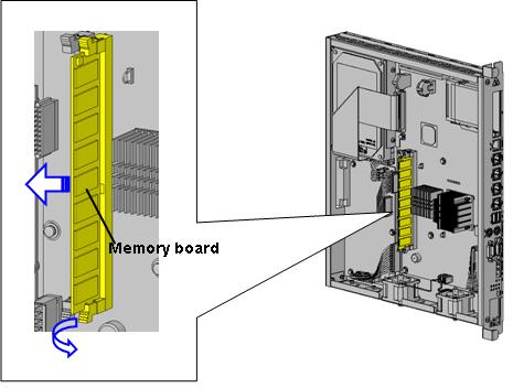
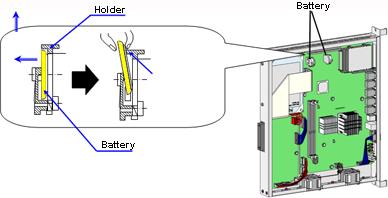
4 TABLE OF CONTENTS... 3 Purpose of This Manual... 5 Intended Audience... 5 SAFETY GUIDELINES... 5 Safety Notation... 5 Before Starting Work... 6 General Precautions... 6 Avoiding Electric Shock... 6 Batteries... 7 Moving the System... 7 Other Precautions OVERVIEW EXTERNAL APPEARANCE COMPONENTS AND PARTS TO BE REMOVED Components to Be Removed DISASSEMBLING THE OP-PANEL DISASSEMBLING THE SVP REMOVING THE TOP COVER REMOVE THE CABLES REMOVE THE HARD DRIVE REMOVE THE PS BOARD REMOVE THE DIMM MEMORY REMOVE THE BATTERY (CR2032 X2) REMOVE THE MAIN BOARD REMOVE THE FAN DISASSEMBLING THE FDD/CD-ROM REMOVING THE TOP AND BOTTOM COVER REMOVING THE SHIELD COVER REMOVING THE UPPER CHASSIS REMOVING CABLES REMOVING A MAIN BOARD REMOVING A MOTOR CONTROL BOARD DISASSEMBLING THE POWER SUPPLY DISASSEMBLING THE POWER SUPPLY PPD Removing the cover Removing Printed Circuit Board Removing the Fan Assembly DISASSEMBLING THE POWER SUPPLY PPD Removing Cover Removing Covers 2 and Remove the Front Assembly Removing Printed Circuit Boards 1, 2, and Removing the Connecter Assembly Removing Printed Circuit Boards 4 to 7 and the Fan DISASSEMBLING THE POWER SUPPLY HS Removing the Cover Removing Printed Circuit Board Removing the Fan Assembly
5 5.4. DISASSEMBLING THE POWER SUPPLY HS Removing the Cover Removing the Front Panel Removing Printed Circuit Boards 1-3 from the Front Removing the Rear Panel Removing Printed Circuit Board 4 at the Rear Removing Printed Circuit Boards Removing Printed Circuit Board Removing the Fan Assembly DISASSEMBLING THE SVR DISASSEMBLING THE HARD DRIVE (HDD) DISASSEMBLING THE BATTERY BOX REMOVING THE COVER REMOVING THE BATTERY REMOVING THE PRINTED CIRCUIT BOARDS 1 AND DISASSEMBLING BATTERY BOX PPH Removing the Cover Removing the Battery Pack Removing the Printed Circuit Boards 1 and REMOVING AND DISASSEMBLING THE AC POWER CABLE REMOVING AND DISASSEMBLING THE AE131A DKC AC POWER CABLE REMOVING AND DISASSEMBLING THE AE173A/AU DKU AC POWER CABLE
6 5
7 6
8 o o o o o o o o o o o 7


9 7
10 8
11 Disassembling the OP-PANEL Disassembling the SVP Disassembling the SVR Disassembling the Hard Drive (HDD) Disassembling Battery Box PPH1003 Removing and Disassembling the AE131A DKC AC Power Cable Disassembling the FDD/CD-ROM 9

12 5 10
13 11
14 Disassembling the SVR Disassembling the Hard Drive (HDD) Disassembling the Power Supply Disassembling the Battery Box Removing and Disassembling the AC Power Cable 12


15 13


16 14
17 15


18 16


19 17


20 18


21 19


22 20


23 CAUTION The CPU heat sink becomes very hot during operation. Allow to cool before touching. 21
24 22


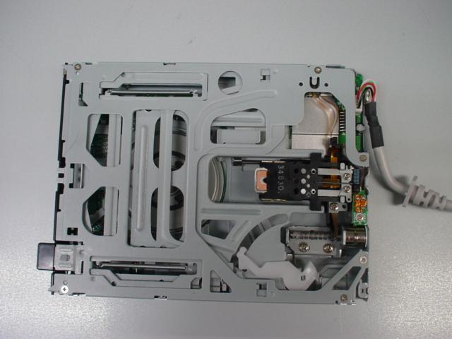
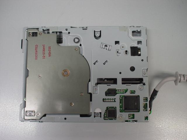
25 Bottom Top Tabs Shield Slide 23


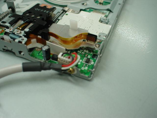

26 Upper chassis Slide FPC cut-off point Connecter 24


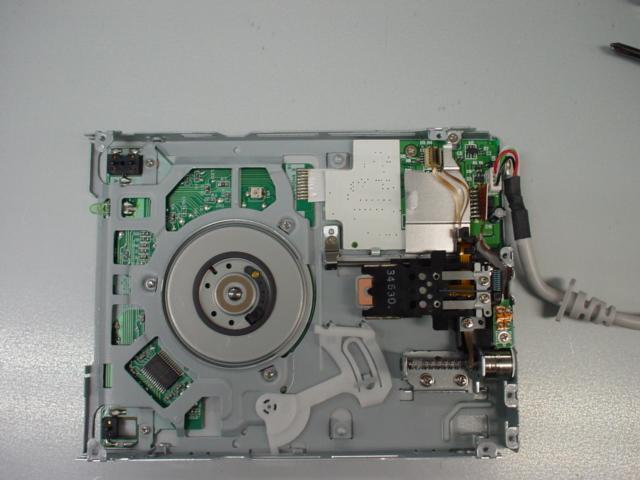

27 FPC cut off point Main board Motor control 25

 SIDE")


28 Cover (a) FRONT PANEL s (b) SIDE PANEL 26


29 Printed Circuit Board s Connector 5 Connector 6 Connector 7 Connector 1 Connector 2 Connector 3 Connector 4 s The attachment hook is released. s Connector Assembly 27


 28")
30 Cover 1 SIDE PANEL Cover 2 (a) Cover 3 TOP PANEL FRONT PANEL (b) 28
")

")

31 2. SIDE PANEL (a) Connector 1 Connector 2 Connector 3 SIDE PANEL (b) Front Assembly 29


32 Printed Circuit Board 1 Printed Circuit Board 2 Printed Circuit Board 3 Connector 1 Connector 2 Connector 3 The attachment hook is released. 30


")
33 Connector 1 Connector 2 Connector 6 Connector 7 Printed Circuit Board 4 Connector 3 Connector 4 Connector 5 Connector 8 (a) (b) Printed Circuit Board 5, 6, 7) Fan 31


34 (c) (b) (a) (c) 3. Printed Circuit Board 1 Connector4 Connector5 The attachment hook is released. Connector1 Connector2 Connector3 Connector Assembly 32


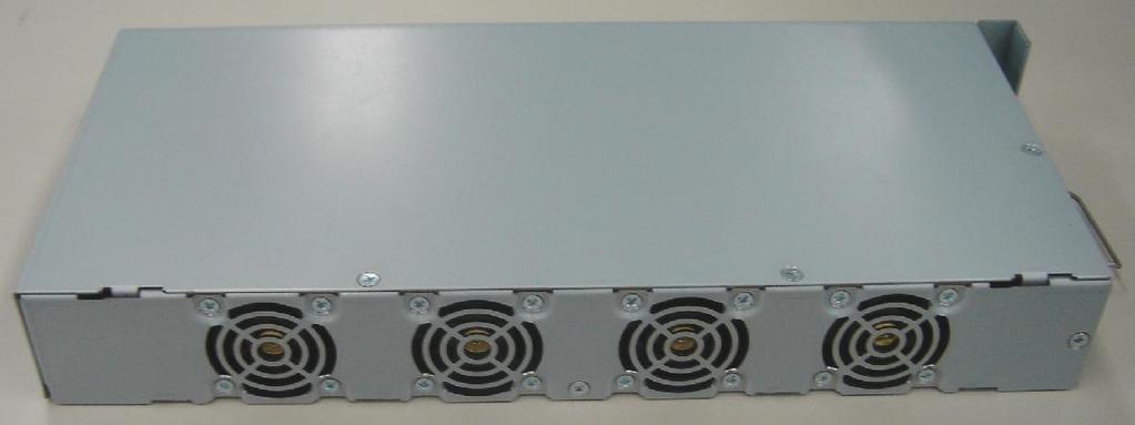
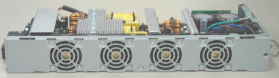
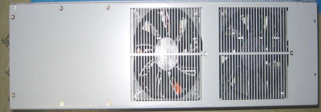
35 Fan Assembly FRONT PANEL Cover 33


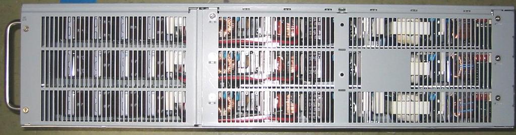
36 FRONT PANEL Connecter1 The attachment hook is released. Connecter2 Connecter3 Top view of the HS2960 Printed Circuit Board 3 Printed Circuit Board 2 Printed Circuit Board 1 Connector1 Connector2 Connector3 Connector4 Prop Connector5 Connector6 34


37 Top view of the HS2950 REAR PANEL Printed Circuit Board 4 REAR PANEL Connector 35

 Board 7 36")
38 Bracket (b) Printed Circuit Board 5-6 Chassis (a) Printed Circuit Board 7 36


39 Fan Assembly Bracket Flange nut Chassis 37
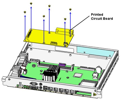
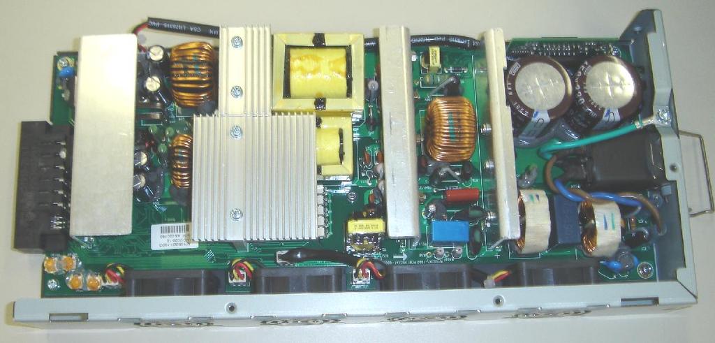
40 Printed Circuit Board 38


41 39


42 Cover 1 Cover 2 パッケージ Printed Circuit 1 Connector コネクタ 1 1 Connector コネクタ 2 2 バッテリーパック Battery ネジ プラケット Bracket コネクタ 3 Connector 3 コネクタ 4 Connector 4 40


43 3. Printed Circuit Board 1 Flat cable and washer Chassis Printed Circuit Board 2 41


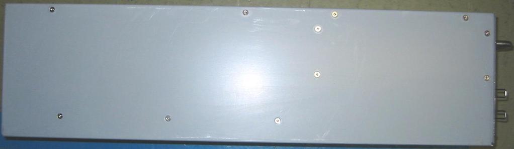
44 Cover 42


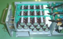
45 Connector 1 Connector 2 Connector 3 Battery pack Connector 4 Bracket Connector 5 Connector 6 Printed Circuit Board 1 Printed Circuit Board 2 Flat cable Chassis Printed Circuit Board 1 43
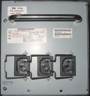
46 Terminal block cover Terminal block cover AC box AE131A DKC (Rear) FG cable AC power cable AC power cable FG cable 44
47 Terminal block cover Terminal block cover AC box AE173A/AU DKU (Rear) FG cable AC power cable AC power cable FG cable 45
Le Disassembly. Required Tools Disassembly Instructions Reassembly Instructions
 Le Div@ Disassembly Required Tools Disassembly Instructions Reassembly Instructions Required Tools All Le Div@ maintenance procedures can be performed using the following tools: Tweezers Small flat-head
Removal and Installation8
 8 Screw Types 8-4 Top Cover Assembly 8-5 Left Hand Cover 8-6 Right Hand Cover 8-10 Front Panel Assembly 8-14 Left Rear Cover 8-15 Right Rear Cover 8-16 Extension Cover (60" Model only) 8-17 Media Lever
Disassembly Manual Version 1.1
 EasyNote K5 Disassembly Manual Version 1.1 Required Tools Disassembly Instructions DIP Switch Setting Reassembly Instructions Required Tools ll EasyNote K5 maintenance procedures can be performed using
Chapter 2: Disassembly
 P370EM / P370EM3 Chapter 2: Overview This chapter provides step-by-step instructions for disassembling the P370EM / P370EM3 series notebook s parts and subsystems. When it comes to reassembly, reverse
Product End-of-Life Disassembly Instructions
 Product End-of-Life Disassembly Instructions Product Category: Personal Computers Marketing Name / Model [List multiple models if applicable.] HP Compaq 8200 Elite USDT Business PC Name / Model #2 Name
Installation & Replacement
 Installation & Replacement Follow the individual procedures to perform the notebook s installation and replacement of various major components. Z70N Series Notebook is a fusion of flexibility, style and
WEASEL N/B MAINTENANCE
 2. System Assembly & Disassembly 2.1 System View 2.1.1 Front View ❶ Microphone Connector ❷ Audio Input Connector ❸ Audio Output Connector ❹ Top Cover Latch ❹ ❶ ❸ ❷ 2.1.2 Left-Side View ❶ VGA Port ❷ S-Video
SCSI Cable Installation Instructions
 Identifying the SCSI Cable Parts SCSI Cable Installation Instructions for HP ProLiant DL100 Series Generation 2 Servers Item Description 1 Connector end 2 240 mm location 3 Terminator end Read instructions
EVGA assumes you have purchased all necessary parts needed to allow for proper system functionality.
 Before You Begin Parts NOT in the Kit This kit contains all the hardware necessary to install and connect your new EVGA e-7050/610i GPU motherboard with integrated GeForce graphics processing. However,
TravelMate 6493 Series Disassembly Instruction
 TravelMate 6493 Series Disassembly Instruction please refer to http://csd.acer.com.tw PRINTED IN TAIWAN Chapter 3 Machine Disassembly and Replacement This chapter contains step-by-step procedures on how
Dell Alienware 13 R3 Heat-Sink Assembly
 Dell Alienware 13 R3 Heat-Sink Assembly Replacement In this guide, we will show you how to remove and replace the Heat-Sink Assembly. Written By: Teren Wallace ifixit CC BY-NC-SA www.ifixit.com Page 1
HP ProLiant DL165 G7 Server
 HP ProLiant DL165 G7 Server Installation Instructions Part Number 601464-003 Identifying server components Front panel components Figure 1 Front Panel Components / 4 3.5 LFF HDD Item Description 1 Thumbscrews
Easy Note Alpha Disassembly. Required Tools Disassembly Instructions Reassembly Instructions
 Easy Note Alpha Disassembly Required Tools Disassembly Instructions Reassembly Instructions Required Tools All Easy Note Alpha maintenance procedures can be performed using the following tools: Tweezers
RACK-220 CHASSIS USER S MANUAL
 RACK-220 CHASSIS USER S MANUAL 1 Copyright Notice This document and product is copyrighted, Jun 1999, by ICP Electronics Inc. All rights are reserved. No part of this manual may be reproduced, copied,
Oracle <Insert Picture Here>
 Slide 1 Oracle Slide 2 WZT-6509 version B Sun Fire Nehalem and Westmere Rack-Mount Server Installation and Replacement Welcome to the installation and replacement
V5420 Host Card Upgrade Kit for R3082D Quick Start Guide
 Quick Start Guide Upgrade kit contents The table below shows the contents of the V5420 Host Card Upgrade Kit (components are not shown to scale). Part Function Pieces V5420 Host Card 1 Host card bracket
HP ProLiant SL160z G6 Server
 HP ProLiant SL160z G6 Server Installation Instructions Part Number 571291-004 Item Description 7 UID LED/SW 8 PCI Slot 9 Health LED 10 Power Button Rear Panel Components Figure 2 Rear panel components
FIELD REPLACEABLE UNIT DOCUMENTATION. Satellite Pro TM Series GENERAL INFORMATION. Tools Required for Proper Disassembly and Reassembly:
 GENERAL INFORMATION Tools Required for Proper Disassembly and Reassembly: 1. Phillips Screwdriver (Size 0&1) 2. Flat head Screwdriver 3. Security Torx (Size 7) 4. Case Separator 5. ESD Wrist Strap 6. ESD
Satellite Pro TM Series GENERAL INFORMATION. Disassembly and Reassembly:
 GENERAL INFORMATION Disassembly and Reassembly: 1. Phillips Screwdriver (Size 0&1) 2. Flat head Screwdriver 3. Case Separator 4. ESD Wrist Strap 5. ESD mats 6. Tweezers Before attempting any of the following
Installation & Replacement
 Chapter 5 Installation & Replacement Follow the individual procedures to perform the notebook s installation and replacement of various major components. Series Notebook balances novelty and mobility in
Chapter 4 Replacement Procedures
 Chapter 4 Replacement Procedures 4 4-ii Satellite P30 Series Maintenance Manual Chapter 4 Contents 4.1 General... 4-1 4.2 Battery... 4-7 4.3 PC Card... 4-8 4.4 HDD... 4-10 4.5 Optical Drive Module... 4-12
Thank you for selecting UTC RETAIL s innovative Model 1170 Point of Sale solution!
 1170 POS SYSTEM 1170 INSTALLATION GUIDE Thank you for selecting UTC RETAIL s innovative Model 1170 Point of Sale solution! This Installation Guide will help you efficiently install the 1170 POS. The document
FIELD REPLACEABLE UNIT DOCUMENTATION
 Satellite TM 1700 Series GENERAL INFORMATION Tools Required for Proper Disassembly and Reassembly: 1. Phillips Screwdriver (Size 1) 2. Flat head screwdriver (5mm) 3. Hex driver (5mm) 4. Case Separator
4.1 General. 4 Replacement Procedures
 4.1 General This chapter explains how to disassemble the computer and replace Field Replaceable Units (FRUs). It may not be necessary to remove all the FRUs in order to replace one. The chart below is
S E R V I C E N O T E
 IINFORMATIION ONLY S E R V I C E N O T E Supersedes: MSO8104A-05 MSO8104A Digitizing Oscilloscope Serial Numbers: MY00000000-MY46001900 SG00000000-SG46001900 The original scopes motherboard is no longer
Upgrading and Servicing Guide
 Upgrading and Servicing Guide The only warranties for Hewlett-Packard products and services are set forth in the express statements accompanying such products and services. Nothing herein should be construed
Disassembly Procedure
 Chapter 2 Disassembly Procedure Please follow the information provided in this section to perform the complete disassembly procedure of the notebook. Be sure to use proper tools described before. SUS A7T
Upgrade & Replacement
 Chapter 5 Upgrade & Replacement Follow the individual procedures in this chapter to perform the notebook s upgrade and replacement of various major components. A sus A6000U Series Notebook is a 2 spindles
HP ProLiant MicroServer
 HP ProLiant MicroServer Installation Sheet Part Number 615715-004 Panel door components Item Component 1 16 screws for HDD installation 2 4 screws for ODD installation 3 Screw driver Rear panel components
Colorful Technology Website:
 Colorful Technology Website: http://www.colorful.cn Thanks for purchasing our based on Intel B250 Chipset motherboard. The motherboard C.B250A-BTC PLUS V20 based on Intel B250 Express Chipset, support
ThinkCentre. Hardware Removal and Replacement Guide Types 8143, 8144, 8146 Types 8422, 8423, 8427
 ThinkCentre Hardware Remoal and Replacement Guide Types 8143, 8144, 8146 Types 8422, 8423, 8427 ThinkCentre Hardware Remoal and Replacement Guide Types 8143, 8144, 8146 Types 8422, 8423, 8427 First Edition
G-MAX TM. ATX Series User s Manual
 Copyright Notice Copyright 2001 Gigabyte Technology. All Rights Reserved. No part of this documentation, including but not limited to the products and software described in it, may be reproduced, transmitted,
Disassembly Procedure
 Chapter 3 Disassembly Procedure Please follow the information provided in this section to perform the complete disassembly procedure of the notebook. Be sure to use proper tools described before. A SUS
Installing the Cisco ADE 2130 and 2140 Series Appliance Hardware Options
 CHAPTER 4 Installing the Cisco ADE 2130 and 2140 Series Appliance Hardware Options This chapter provides instructions for installing, replacing, and removing various hardware options in your Cisco ADE
Nvidia Quadro FX 5600 graphics card and auxiliary power adapter cable installation
 Nvidia Quadro FX 5600 graphics card and auxiliary power adapter cable installation HP xw8600 and xw9400 Workstations This document describes how to install an Nvidia Quadro FX 5600 graphics card and an
X500 Parts Replacement Instructions
 X500 Parts Replacement Instructions This document is intended for service personnel. It provides information not found in the user manual. For information such as replacing the battery pack, hard disk
Product End-of-Life Disassembly Instructions Product Category: Personal Computers
 Product End-of-Life Disassembly Instructions Product Category: Personal Computers Marketing Name / Model [List multiple models if applicable.] HP ProDesk 400 G3 MT Business PC Name / Model #2 Name / Model
S4M 10/100 Internal ZebraNet PrintServer, Wireless Print Server, Parallel Port, and No Comm Option Kits
 S4M 0/00 Internal ZebraNet PrintServer, Wireless Print Server, Parallel Port, and No Comm Option Kits Installation Instructions This kit includes the parts and documentation necessary to install the 0/00
Installing System Board Options
 CHAPTER 8 Installing System Board Options This section describes how to install the following options: Expansion cards Memory modules Microprocessor This section also includes instructions for replacing
SySTIUM TM TECHNOLOGIES Model 215
 SySTIUM TM TECHNOLOGIES Model 215 MotherBoard Ready SM System ASSEMBLY GUIDE SySTIUM TM TECHNOLOGIES MOTHERBOARD READ Y SM SYSTEM MODEL 215 Radio Frequency Interference Notice (USA) This equipment has
XPS 15 2-in-1. Service Manual. Computer Model: XPS Regulatory Model: P73F Regulatory Type: P73F001
 XPS 15 2-in-1 Service Manual Computer Model: XPS 15-9575 Regulatory Model: P73F Regulatory Type: P73F001 Notes, cautions, and warnings NOTE: A NOTE indicates important information that helps you make better
19 Rackmount Cases A3211. Enrich Your Product Line and Build Your Brand Awareness
 19 Rackmount Cases A3211 Enrich Your Product Line and Build Your Brand Awareness 0303-00283 USER S MANUAL Table of Contents 1. Introduction. 1 2. Standard parts. 2 2-1 Disassembly of the Top Cover...2
Figure 4-29 Removing the CPU compartment cover
 4 Replacement Procedures 4.9 CPU 4 4.9 CPU Removing the CPU To remove the CPU, follow the steps below. 1. Turn the computer upside down and remove two M2.5 4 security screws securing the CPU compartment
H4 Series Hardware Replacement Guide
 Machine type: 10059/7723 10060/7724 10068/7752 10080/3099/1194 10091/2558/1196 H4 Series Hardware Replacement Guide Version 3.0 2011.08 31500379 Hardware Replacement Guide Copyright Lenovo 2011. All rights
ASUS A2000 Series Notebook consists of various modules. This chapter
 Chapter 2 Disassembly Procedure Please follow the information provided in this section to perform the complete disassembly procedure of the notebook. Be sure to use proper tools described before. ASUS
Dell Inspiron XPS and Inspiron 9100 Service Manual
 Dell Inspiron XPS and Inspiron 9100 Service Manual Dell Inspiron XPS and Inspiron 9100 Service Manual Before You Begin Memory Module, Mini PCI Card, and Devices System Components Subwoofer Bluetooth Card
Disassembly Procedure
 Chapter 3 Disassembly Procedure Please follow the information provided in this section to perform the complete disassembly procedure of the notebook. Be sure to use proper tools described before. A SUS
Parts list. Overall. For T20, T21 and T22. 3 l k. 146 ThinkPad T20, T21, T22 (MT 2647/2648)
") Overall Parts list For T20, T21 and T22 24 1 23 22 a 21 20 b 2 19 18 c d 3 l 17 16 15 14 k h 4 i e f g 5 13 6 7 12 11 j 10 9 8 146 ThinkPad T20, T21, T22 (MT 2647/2648) v Each FRU is available for all
Overall Parts list For T20, T21 and T22 24 1 23 22 a 21 20 b 2 19 18 c d 3 l 17 16 15 14 k h 4 i e f g 5 13 6 7 12 11 j 10 9 8 146 ThinkPad T20, T21, T22 (MT 2647/2648) v Each FRU is available for all
Upgrading and Servicing Guide
 Upgrading and Servicing Guide The information in this document is subject to change without notice. Hewlett-Packard Company makes no warranty of any kind with regard to this material, including, but not
HP UPS R/T3000 ERM. Overview. Precautions. Installation Instructions
 HP UPS R/T3000 ERM Installation Instructions Overview The ERM consists of two battery packs in a 2U chassis. The ERM connects directly to a UPS R/T3000 or to another ERM. Up to two ERM units can be connected.
Print Mechanism Maintenance Kit
 Print Mechanism Maintenance Kit Installation Instructions This kit includes the parts and documentation necessary to install the print mechanism maintenance kit in the following printers: ZT0 ZT0 ZT0 Read
Computer Assembly (Installing Mother Board & CPU)
") Computer Assembly (Installing Mother Board & CPU) IT@SCHOOL HARDWARE TEAM Biju Thiruvananthapuram Sree Kumar Kottarakkara Shamsudeen Attingal Pradeep Mattara Wandoor Pre-Installation Precaution Mother
Computer Assembly (Installing Mother Board & CPU) IT@SCHOOL HARDWARE TEAM Biju Thiruvananthapuram Sree Kumar Kottarakkara Shamsudeen Attingal Pradeep Mattara Wandoor Pre-Installation Precaution Mother
Cube YY-0420/0430 Technical Instruction
 Cube YY-0420/0430 Technical Instruction Contact Information YEONG YANG Technology Co., Ltd. Address 12F, 778-1, Chung Cheng Road, Chung-Ho City, Taipei, Taiwan, R.O.C. Telephone +886-2-3234-0020 Fax +886-2-3234-0014
ALIENWARE AURORA SERVICE MANUAL 01/
 ALIENWARE AURORA SERVICE MANUAL 01/ 01 Notes, Cautions, and Warnings NOTE: A NOTE indicates important information that helps you make better use of your computer. CAUTION: A CAUTION indicates either potential
Intel NUC Kit NUC5i3MYHE & NUC5i5MYHE User Guide. Intel NUC Kit NUC5i3MYHE Intel NUC Kit NUC5i5MYHE User Guide
 Intel NUC Kit NUC5i3MYHE Intel NUC Kit NUC5i5MYHE User Guide 1 Before You Begin CAUTIONS The procedures in this user guide assume familiarity with the general terminology associated with personal computers
Intel NUC Kit NUC7i3BNHX1 with Intel Optane Memory. Intel NUC Kit NUC7i5BNHX1 with Intel Optane Memory
 Intel NUC Kit NUC7i3BNHX1 with Intel Optane Memory Intel NUC Kit NUC7i5BNHX1 with Intel Optane Memory Intel NUC Kit NUC7i7BNHX1 with Intel Optane Memory User Guide 1 Before You Begin CAUTIONS The procedures
ww.battery-adapter.com
 Removing and replacing an FRU Lenovo G470/G475/G570/G575 This section presents exploded figures with the instructions to indicate how to remove and replace the FRU. Make sure to observe the following general
Product End-of-Life Disassembly Instructions Product Category: Personal Computers
 Product End-of-Life Disassembly Instructions Product Category: Personal Computers Marketing Name / Model [List multiple models if applicable.] OMEN X by HP Desktop PC 900 Purpose: The document is intended
Disassembly Procedure
 Chapter 2 Disassembly Procedure Please follow the information provided in this section to perform the complete disassembly procedure of the notebook. Be sure to use proper tools described before. A SUS
Rear Consumer LCD Hinge Assembly Large Displays
 7403-K454 Rear Consumer LCD Hinge Assembly Large Displays Kit Instructions Issue D Revision Record Issue Date Remarks A Nov 2008 First issue B June 2009 Removed Power Cable from the kit contents C May
1.1.Packing Contents 1*Colorful C.B250A-BTC V20 motherboard 2*SATA cables 1*Driver/Utility CD 1*User's Guide 1*I/O shield 1.2.MOTHERBOARD SPEC CPU
 Colorful Technology Website: http://www.colorful.cn Thanks for purchasing our based on Intel B250 Chipset motherboard. The motherboard C.B250A-BTC V20 based on Intel B250 Express Chipset, support Intel
3 1 ROM. Installation Manual
 3 1 ROM Installation Manual 3.1 ROM Installation Instructions Please read the following cartfully The following installation sequences should be performed by an authorised Amiga Technologies service centre,
Ollee Ultra Mini PC, a Mini PC with 32GB emmc and Windows 10 Pro MAPMG. Ollee Ultra Mini PC, a Mini PC with 120GB SSD and Windows 10 Pro MAPMG1
 Ollee Ultra Mini PC, a Mini PC with 32GB emmc and Windows 10 Pro MAPMG Ollee Ultra Mini PC, a Mini PC with 120GB SSD and Windows 10 Pro MAPMG1 User Guide Before You Begin CAUTIONS The procedures in this
Z-MACHINE GT900. English. English version
 English English version www.zalman.co.kr www.zalmanusa.com Table of Contents 1. Safety Notices 3 2. Components 4 3. Specifications 6 4. Front Panel Buttons and I/O Ports 7 5. Installation Guide8 2 (1)
SySTIUM TECHNOLOGIES. Assembly Guide. Model 133i
 Assembly Guide Model 133i Radio Frequency Interference Notice (USA) This equipment has been tested and found to comply with the limits for a Class B digital device, pursuant to Part 15 of the FCC Rules,
Chapter 4 Replacement Procedures
 Chapter 4 Replacement Procedures 4 Replacement Procedures 4-ii Satellite A40 Maintenance Manual (960-458) 4 Replacement Procedures Chapter 4 Contents 4.1 General... 4-1 4.2 Battery pack... 4-8 4.3 PC card...
Installation & Replacement
 Installation & Replacement Follow the individual procedures to perform the notebook s installation and replacement of various major components. Z30N Series Notebook balances novelty and mobility in an
Tower to Rack and Rack to Tower System Conversion Guide
 Tower to Rack and Rack to Tower System Conversion Guide HP Workstation zx6000 HP Server rx2600 Manufacturing Part Number : A7857-90017 Edition E0802 Copyright 2002 Hewlett-Packard Company. Legal Notices
HP ProLiant DL380 Generation 3 Server Maintenance and Service Guide. May 2003 (Third Edition) Part Number
 Part Number") HP ProLiant DL380 Generation 3 Server Maintenance and Service Guide May 2003 (Third Edition) Part Number 291916-003 2003 Hewlett-Packard Development Company, L.P. Microsoft, Windows, and Windows NT are
HP ProLiant DL380 Generation 3 Server Maintenance and Service Guide May 2003 (Third Edition) Part Number 291916-003 2003 Hewlett-Packard Development Company, L.P. Microsoft, Windows, and Windows NT are
Chapter 4 Replacement Procedures
 Chapter 4 Replacement Procedures 4 Replacement Procedures 4 4-ii Satellite R10 Maintenance Manual (960-509) 4 Replacement Procedures Chapter 4 Contents 4.1 Overview... 4-1 Safety Precautions... 4-2 Before
Intel NUC7 Home, a Mini PC with Windows 10 NUC7i3BNHXF. Intel NUC7 Home, a Mini PC with Windows 10 NUC7i5BNHXF
 Intel NUC7 Home, a Mini PC with Windows 10 NUC7i3BNHXF Intel NUC7 Home, a Mini PC with Windows 10 NUC7i5BNHXF Intel NUC7 Enthusiast, a Mini PC with Windows 10 NUC7i7BNHXG User Guide 1 Before You Begin
Intel NUC Kit NUC6CAYS User Guide
 Intel NUC Kit NUC6CAYS User Guide Regulatory Model NUC6CAY 1 Before You Begin CAUTIONS The procedures in this user guide assume familiarity with the general terminology associated with personal computers
MT-150. RENOGY 150A Peak High Precision Watt Meter and Power Analyzer E. Philadelphia St., Ontario CA Version: 1.
 MT-150 RENOGY 150A Peak High Precision Watt Meter and Power Analyzer 0 2775 E. Philadelphia St., Ontario CA 91761 1-800-330-8678 Version: 1.1 Important Safety Instructions Please save these instructions.
Installation Instructions
 Installation Instructions This document provides information on: important pre-installation considerations power supply requirements installing the module connecting the wiring using the indicators for
SC832/SC833 CHASSIS USER'S GUIDE
 R! 2 1 MUTE RESET SUPER SC832/SC833 CHASSIS USER'S GUIDE 1.0 SUPER SC832/SC833 Chassis User s Guide The information in this User s Guide has been carefully reviewed and is believed to be accurate. The
This 4200-RM Rack Mount Kit is for installation in 4200-CAB series cabinets only.
 Keithley Instruments, Inc. 28775 Aurora Road Cleveland, Ohio 44139 (440) 248-0400 Fax: (440) 248-6168 www.keithley.com Model 4200-RM Rack Mount Kit Packing List Introduction NOTE This 4200-RM Rack Mount
midi LOGGER 900 SERVICE MANUAL GL900-UM-251 GL900-UM
 midi LOGGER 900 GL900-UM-251 SERVICE MANUAL GL900-UM-251-01-9370 HISTORY OF REVISIONS No. Date issued Description of revision Page Edition 1 08.07.26 First Printing All 01 GL900-UM-251-9370 i TO ENSURE
Table of Contents - 1. Predator PO3-600 User s Guide
 Table of Contents - 1 Predator PO3-600 User s Guide 2 - Upgrading your Computer 2018. All Rights Reserved. Desktop Computer Covers: Tower models This revision: April 2018 V1.00 Important This manual contains
Intel NUC Kit DN2820FYKH User Guide. Intel NUC Kit DN2820FYKH User Guide
 Intel NUC Kit DN2820FYKH User Guide 1 Before You Begin CAUTIONS The procedures in this user guide assume familiarity with the general terminology associated with personal computers and with the safety
Hardware Replacement Guide
 Hardware Replacement Guide Types 6491, 8013, 8702, 8706 Types 8716, 8970, 8972, 8976 Types 8980, 8982, 8986, 8992 Types 8994, 9266, 9276, 9278 Types 9282, 9286, 9288, 9374 Types 9378, 9380, 9384, 9628
4.1 General 4 Replacement Procedures
 4.1 General 4 Replacement Procedures 4 1 4.1 General This chapter explains how to disassemble the computer and replace Field Replaceable Units (FRUs). Some replacement procedures may not require you to
Dell Inspiron 660 Owner s Manual
 Dell Inspiron 660 Owner s Manual Computer model: Inspiron 660 Regulatory model: D11M Regulatory type: D11M002 Notes, Cautions, and Warnings NOTE: A NOTE indicates important information that helps you make
8806 Series. 15 Multi-functional Touch Panel PC. Quick Reference Guide
 8806 Series 15 Multi-functional Touch Panel PC Quick Reference Guide 1st Ed 10 July, 2009 8806 Contents 1. Getting Started...3 1.1 Safety Precautions...3 1.2 Packing List...3 1.3 System Specifications...4
Serial ATA Hot Swap Drive Cage Upgrade Kit for: Intel Server Chassis SC5200 Intel Server Chassis SC5250-E
 Serial ATA Hot Swap Drive Cage Upgrade Kit for: Intel Server Chassis SC5200 Intel Server Chassis SC5250-E A Guide for Technically Qualified Assemblers of Intel Identified Subassemblies/Products Order Number:
Vector Drive - Troubleshooting Guide
 Haas Technical Documentation Vector Drive - Troubleshooting Guide Scan code to get the latest version of this document Translation Available The Haas Vector drive is the source of power for the spindle
1 Getting Started Installing & Configuring
 Before you begin Installation and Setup Instructions for E-Series 60-Drive Trays E760 and E5660 controller-drive trays DE6600 expansion drive trays Unpack & Prepare Install Hardware Connect Drive Trays
Intel NUC Kit D54250WYKH & D34010WYKH User Guide. Intel NUC Kit D54250WYKH Intel NUC Kit D34010WYKH User Guide
 Intel NUC Kit D54250WYKH Intel NUC Kit D34010WYKH User Guide 1 Before You Begin CAUTIONS The procedures in this user guide assume familiarity with the general terminology associated with personal computers
Vector Drive - Troubleshooting Guide
 Haas Technical Documentation Vector Drive - Troubleshooting Guide Scan code to get the latest version of this document Translation Available The Haas Vector drive is the source of power for the spindle
Installation & Replacement
 Installation & Replacement Follow the individual procedures to perform the notebook s installation and replacement of various major components. Z31N Series Notebook balances novelty and mobility in an
Dell Precision 3430 Small Form Factor
 Dell Precision 3430 Small Form Factor USB Type-C card Installation Guide Regulatory Model: D11S Regulatory Type: D11S004 Notes, cautions, and warnings NOTE: A NOTE indicates important information that
HP Touchsmart 300 Power Supply Replacement
 HP Touchsmart 300 Power Supply Replacement This details how to replace a defective power supply, e.g., with a new one from the HP Parts Store or other source. Geschreven door: Glenn P INTRODUCTIE This
Series 3700 Screw Terminal Assemblies Installation Instructions
 Keithley Instruments, Inc. 28775 Aurora Road Cleveland, Ohio 44139 1-888-KEITHLEY www.keithley.com Series 3700 Screw Terminal Assemblies Installation Instructions Introduction This document contains handling
Intel NUC Kit NUC7i7BNH Intel NUC Kit NUC7i5BNH Intel NUC Kit NUC7i3BNH
 Intel NUC Kit NUC7i7BNH Intel NUC Kit NUC7i5BNH Intel NUC Kit NUC7i3BNH User Guide 1 Before You Begin CAUTIONS The procedures in this user guide assume familiarity with the general terminology associated
Vector Drive - Troubleshooting Guide
 Haas Technical Documentation Vector Drive - Troubleshooting Guide Scan code to get the latest version of this document Translation Available The Haas Vector drive is the source of power for the spindle
PlayStation 3 Teardown PS3. Written By: Mint137. ifixit CC BY-NC-SA Page 1 of 22
 PlayStation 3 Teardown PS3 Written By: Mint137 ifixit CC BY-NC-SA www.ifixit.com Page 1 of 22 INTRODUCTION This is a teardown of an original launch 60GB PlayStation 3 system. One of the best units out
Firebox X Peak De-manufacturing Instructions
 Firebox X Peak De-manufacturing Instructions Document Number: 480-2528-001 WatchGuard Technologies. Doc #480-2528-001 Rev. A Page 1 of 18 1.0 Purpose This instruction defines the de-manufacturing process
Introducing the Cisco 1121 Secure Access Control System Hardware
 CHAPTER 2 Introducing the Cisco 1121 Secure Access Control System Hardware This chapter gives an overview of the Cisco 1121 Secure Access Control System (CSACS-1121) hardware. It covers the appliance hardware,
Arcserve UDP 8100 and UDP 8200
 HARDWARE INSTALLATION GUIDE Arcserve UDP 8100 and UDP 8200 Appliance Hardware Installation Guide Table of Contents Section 1 Safety Notice and Warnings........................................... 3 Section
HP Pavilion dv7-6c90us Cooling fan Replacement
 HP Pavilion dv7-6c90us Cooling fan Replacement This guide will walk you through the process of replacing the cooling fan in an HP Pavilion dv7 laptop. Written By: Angelina Clayton ifixit CC BY-NC-SA www.ifixit.com
Computer Maintenance. PC Disassembly and Reassembly. Copyright Texas Education Agency, All rights reserved.
 Computer Maintenance PC Disassembly and Reassembly 1 Enabling Objectives Computer Chassis (Cases) Power Supplies Configuring the Motherboard Configuring the Connectors CPU Interfaces RAM Installing a Hard