Microprocessors B (17.384) Spring Lecture Outline
|
|
|
- Clemence Paul
- 6 years ago
- Views:
Transcription
1 Microprocessors B (17.384) Spring 2013 Lecture Outline Class # 04 February 12, 2013 Dohn Bowden 1
2 Today s Lecture Administrative Microcontroller Hardware and/or Interface Programming/Software Lab Homework 2
3 Course Admin 3
4 Administrative Admin for tonight Syllabus Highlights Lab #1 is due in 2 weeks Tuesday (February 26 th ) Start Lab #2 NO CLASS NEXT WEEK Tuesday is a Monday Class Schedule In TWO Weeks NO lecture Lab only Attendance is required 4
5 Syllabus Review Week Date Topics Lab Lab Report Due 1 01/22/13 PIC pin out, General-purpose IO, C programming 2 01/29/13 LED/Switch Input / Output and Power Saving Modes /05/13 Lab 1 con t 4 02/12/13 Timers, Interrupts, interrupt-driven IO 2 X 02/19/13 No Class Monday Class Schedule 5 02/26/13 Lab 2 con t /05/13 Asynchronous/Synchronous Serial IO (UART, I 2 C, SPI) 3 X 03/12/13 No Class Spring Break 7 03/19/13 Examination /26/13 Lab 3 con t /02/13 Pulse Width Modulation and DC motor control /09/13 Lab 4 con t /16/13 Advanced Hardware Topics Project 12 04/23/13 Examination /30/13 Work on Course Project Project /07/13 Final Exam/Course Project Brief and Demonstration Demo 5
6 Microcontroller Hardware and / or Interfaces 6
7 Timers 7
8 Timers PIC24 Timers are very similar to the PIC16 Timers from Microprocessors A (17.383) As you recall A Timer Is a counter 8
9 Timers All timer/counters have unique features but Also have some characteristics that are common 9
10 Timers A source is required Either be a synchronous clock provided by an oscillator or An event that isn t so periodic such as a pushbutton connected to the Timerx Clock Input pin (TxCKI) 10
11 Timers Current value is stored in an 8 to 16-bit register located in data memory A binary value in this register will increment by one depending on a selected edge of a signal transition Example if we configured the module to increment on the negative edge of a signal the value register would increase by one every time a high-to-low transition on the source is encountered 11
12 Scalers 12
13 Timers Each timer/counters has at least one scaler Scalers are before (prescaler) and/or after (postscaler) A scaler works by dividing an input signal by a specific value 13
14 Prescaler A prescaler Used to reduce the frequency to a lower frequency by integer division Available prescale values are
15 Example 15
16 Prescaler Scaler example Input signal = F CY = 1000 Hz PRE = prescaler set to 2 16
17 Prescaler Scaler example Input signal = F CY = 1000 Hz PRE = prescaler set to 2 Period = T CY = 1/F CY = 1/1000 = 1 msec Period = T CY = PRE/F CY = 2/1000 = 2 msec (slowed down) New frequency = 1/2mSec = 500 Hz 17
18 Timers 18
19 Timer Classifications 16-bit timers are classified into three types to account for their functional differences Type A time base Type B time base Type C time base 19
20 Type A Timers At least one Type A timer is available on most PIC devices. For most PIC devices Timer1 is a Type A timer A Type A timer has the following unique features over other types: Can be operated from the device Low Power 32 khz Oscillator Can be operated in an Asynchronous mode from an external clock source In particular, the unique features of a Type A timer allow it to be used for Real-Time Clock (RTC) applications 20
21 Type B Timers Timer2 and Timer4 (if present) are Type B timers on most PICs Type B timer has the following unique features over other types of timers Can be concatenated with a Type C timer to form a 32-bit timer The TxCON register for a Type B timer has the T32 control bits to enable the 32-bit timer function The clock synchronization for a Type B timer is performed after the prescale logic 21
22 Type C Timers Timer3 and Timer5 (if available) are Type C timers on most PICs Type C timer has the following unique features over other types of timers Can be concatenated with a Type B timer to form a 32-bit timer On a given device, at least one Type C timer has the ability to trigger an A/D conversion 22
23 PIC24 Timers 23
24 PIC24 Timers Timers Three 16-bit timers Timer 1 Timer 2 Timer 3 Can combine Timers 2 and 3 16-bit timers into One 32-bit timer (Timer2/3) 24
25 Timers As a 32-bit timer the Timer2/3 feature permits operation in three modes Two Independent 16-bit timers (Timer2 and Timer3) with all 16- bit operating modes (except Asynchronous Counter mode) Single 32-bit timer (Timer2/3) Single 32-bit synchronous counter (Timer2/3) 25
26 Timer 1 26
27 Timer1 Block Diagram of Timer 1 all other timers are similar 27
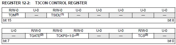
28 Timer1 TON Timer1 On bit 1 = Starts 16-bit Timer1 0 = Stops 16-bit Timer1 28
29 Timer1 TCS Timer1 Clock Source Select bit 1 = External clock from pin T1CK (on the rising edge) 0 = Internal clock (T CY ) 29
30 Gated Timer Mode Gated Timer Mode Used to measure the duration of an external gate signal The timer increments by one on every rising edge of the input clock As long as the external gate signal at the TxCK pin is high The timer interrupt is generated on the falling edge of the TxCK pin 30
31 Gated Timer Mode Gated Timer Mode 31
32 Timer1 TGATE Timer1 Gated Time Accumulation Enable bit When TCS = 1 This bit is ignored When TCS = 0 1 = Gated time accumulation enabled 0 = Gated time accumulation disabled 32
33 Timer1 TCKPS<1:0> Timer1 Input Clock Prescale Select bits 11 = 1: = 1:64 01 = 1:8 00 = 1:1 33
34 Timer1 TSYNC Timer1 External Clock Input Synchronization Select bit Choose either synchronous or asynchronous operation 34
35 Timer1 TSYNC Timer1 External Clock Input Synchronization Select bit When TCS = 1 TSYNC = 1 = Synchronize external clock input TSYNC = 0 = Do not synchronize ext clock input When TCS = 0 TSYNC bit is ignored (using internal clock) 35
36 PRx and TMRx Timers have two registers which are important Period Register (PRx) TiMer Register (TMRx) The timer counts by incrementing the value of the TMRx register until its value equals the value of the PRx register At that moment TMRx register automatically reset to zero and process repeats AND the moment TMRx equals PRx an interrupt is generated if interrupts are enabled 36
37 Timer1 Period Register (PRx) and the Timer Register (TMRx) 37
38 Timer Modes Configuration RECALL TCS Timer1 Clock Source Select bit 1 = External clock from pin T1CK (on the rising edge) 0 = Internal clock (T CY ) 38
39 Calculate Interrupt Time 39
40 Calculate Interrupt Time Clock Frequency F CY Clock period 1/F CY = T CY Prescaler PRE Interrupt Time T interrupt T interrupt = (PRx+1) x PRE x T CY = (PRx+1) x PRE/F CY Period Register PRx PRx = (T interrupt x F CY /PRE ) 1 40
41 Example 41
42 Calculate Interrupt Time Example Determine time of interrupt for the following F CY = 10MHz PRE =
43 Calculate Interrupt Time Example Determine time of interrupt for the following F CY = 10MHz PRE = 256 PRx = Clock period = T CY = 1/F CY = 1/10MHz = 100 nsec T interrupt = (PRx+1) x PRE x T CY = (PRx+1) x PRE/F CY = = ( )(256)/(10MHz) = seconds 43
44 Example 44
45 Calculate Interrupt Time Example Determine value for PRx given the following F CY = 10MHz PRE = 256 T interrupt = 0.25 seconds 45
46 Calculate Interrupt Time Example Determine value for PRx given the following F CY = 10MHz PRE = 256 T interrupt = 0.25 seconds Clock period = T CY = 1/F CY = 1/10MHz = 100 nsec PRx = (T interrupt x F CY /PRE ) 1 = = (0.25)(10MHz)/(256) -1 =
47 Determining Timer Interrupts PRx will equal the value in TMRx When the interrupt will occur 47
48 Configure Timer1 For Operation 48
49 To Configure Timer1 For Operation IMPORTANT Timer bits in the three timer control registers share many of the same names therefore RECALL that we must use the following nomenclature to assign bit values Use registername.bitname Because bitnames in these registers are NOT UNIQUE, therefore DO NOT use just _bitname Bit names that are NOT UNIQUE will not be defined in our header file 49


50 Timer Control Registers 50
51 To Configure Timer1 For Operation EXAMPLE Set T1CON TON bit (not unique to T1CON register) 51
52 To Configure Timer1 For Operation EXAMPLE Set T1CON TON bit (not unique to T1CON register) T1CONbits.TON = 1; 52
53 To Configure Timer1 For Operation 1. Set the TON bit (= 1) in the T1CON register 2. Select the timer prescaler ratio using the TCKPS<1:0> bits in the T1CON register 3. Set the Clock and Gating modes using the TCS and TGATE bits in the T1CON register 4. Set or clear the TSYNC bit in T1CON to select synchronous or asynchronous operation 5. Load the timer period value into the PR1 register 6. If interrupts are required, set the interrupt enable bit, T1IE. Use the priority bits, T1IP<2:0>, to set the interrupt priority. 53
54 Timer 2 54
55 Timer2 Block Diagram 55
56 T2IF Period The T2IF flag is set at the following period (T t2if ) T t2if = (PR2+1) x PRE x Tcy = (PR2+1) x PRE/Fcy Observe that because Timer2 is a 16-bit timer, if PR2 is its maximum value of 0xFFFF (65535), and the prescaler is 1, this is just: T t2if = x 1/Fcy We typically want to solve for T t2if, given a PRE value PR2 = (T t2if x Fcy /PRE ) 1 56
57 Example T2IF Periods 57
58 Timers The Timer2/3 feature also supports Timer gate operation Selectable Prescaler Settings Timer operation during Idle and Sleep modes Interrupt on a 32-bit Period Register Match Time Base for Input Capture and Output Compare Modules (Timer2 and Timer3 only) ADC1 Event Trigger (Timer2/3 only) 58
59 32-Bit Timer Configuration 59
60 To configure Timer2 32-Bit Operation To configure the Timer2 feature for 32-bit operation 1. Set the corresponding T32 control bit 2. Select the prescaler ratio for Timer2 using the TCKPS<1:0> bits. 3. Set the Clock and Gating modes using the corresponding TCS and TGATE bits 4. Load the timer period value. PR3 contains the most significant word of the value, while PR2 contains the least significant word 5. Set the interrupt enable bit T3IE, if interrupts are required. Use the priority bits T3IP<2:0> to set the interrupt priority. While Timer2 controls the timer, the interrupt appears as a Timer3 interrupt. 6. Set the corresponding TON bit 60
61 To configure Timer2 32-Bit Operation Therefore 1. Set the corresponding T32 control bit T3CONbits.TON = 0; // Stop any 16-bit Timer3 operation T2CONbits.TON = 0; // Stop any 16/32-bit Timer3 operation T2CONbits.T32 = 1; // Enable 32-bit Timer mode 61
62 To configure Timer2 32-Bit Operation 2. Select the prescaler ratio for Timer2 using the TCKPS<1:0> bits T2CONbits.TCKPS = 0b00// Select 1:1 Prescaler 62
63 To configure Timer2 32-Bit Operation 3. Set the Clock and Gating modes using the corresponding TCS and TGATE bits T2CONbits.TCS = 0; // Select internal instruction cycle clock T2CONbits.TGATE = 0; // Disable Gated Timer mode 63
64 To configure Timer2 32-Bit Operation 4. Load the timer period value. PR3 contains the most significant word of the value, while PR2 contains the least significant word PR3 = 0x0002; // Load 32-bit period value (msw) PR2 = 0x0000; // Load 32-bit period value (lsw) 64
65 To configure Timer2 32-Bit Operation 5. Set the interrupt enable bit T3IE, if interrupts are required. Use the priority bits T3IP<2:0> to set the interrupt priority. While Timer2 controls the timer, the interrupt appears as a Timer3 interrupt IPC2bits.T3IP = 0x01; // Set Timer3 Interrupt Priority Level IFS2bits.T3IF = 0; // Clear Timer3 Interrupt Flag IEC0bits.T3IE = 1; // Enable Timer3 interrupt 65
66 To configure Timer2 32-Bit Operation 6. Set the corresponding TON bit T2CONbits.TON = 1; // Start 32-bit Timer 66
67 In Summary To configure Timer2 in 32-Bit Operation T3CONbits.TON = 0; T2CONbits.TON = 0; T2CONbits.T32 = 1; T2CONbits.TCS = 0; T2CONbits.TGATE = 0; T2CONbits.TCKPS = 0b00 TMR3 = 0x00; TMR2 = 0x00; PR3 = 0x0002; PR2 = 0x0000; IPC2bits.T3IP = 0x01; // Stop any 16-bit Timer3 operation // Stop any 16/32-bit Timer3 operation // Enable 32-bit Timer mode // Select internal inst cycle clock // Disable Gated Timer mode // Select 1:1 Prescaler // Clear 32-bit Timer (msw) // Clear 32-bit Timer (lsw) // Load 32-bit period value (msw) // Load 32-bit period value (lsw) // Set Timer3 Interrupt Priority Level Continued next page. 67
68 In Summary To configure Timer2 in 32-Bit Operation IFS2bits.T3IF = 0; IEC0bits.T3IE = 1; T2CONbits.TON = 1; // Clear Timer3 Interrupt Flag // Enable Timer3 interrupt // Start 32-bit Timer /* Example code for Timer3 ISR*/ void attribute (( interrupt, shadow )) _T3Interrupt(void) { /* Interrupt Service Routine code goes here */ IFS0bits.T3IF = 0; //Clear Timer3 interrupt flag } 68
69 In Summary To configure Timer2 in 32-Bit Operation The timer value at any point is stored in The register pair TMR3:TMR2 TMR3 always contains the Most significant word (msw) of the count TMR2 contains the least significant word (lsw) 69
70 16-Bit Timer Configuration 70
71 To configure Timer2 16-Bit Operation To configure any of the timers for Individual 16-bit operation The process is similar Refer to the Family reference manual for timers» Section 11 71
72 Where do we head from here? 72
73 Interrupts 73
74 Interrupts To utilize the interrupt feature of the Timers and other module We need to have an understanding of Interrupts and How they work! 74
75 Interrupt Basics 75
76 Polled Input / Output Polled Input / Output (IO) Processor continually checks IO device to see if it is ready for data transfer Inefficient processor wastes time checking for ready condition Either checks too often or not often enough 76
77 PIC24 μc Interrupt Operation The normal program flow main() is referred to as The foreground code The Interrupt Service Routine (ISR) is referred to as The background code 77
78 PIC24 μc Interrupt Operation Code that executes when the interrupt occurs is The interrupt service routine (ISR) The ISR Responds to whatever event triggered the interrupt 78
79 PIC24 μc Interrupt Operation During normal program execution If we have an interrupt the following will occur 79
80 Interrupt Driven Input / Output Interrupt Driven Input / Output (IO)... IO device interrupts processor when it is ready for data transfer Processor can be doing other tasks while waiting for last data transfer to complete very efficient All IO in modern computers are interrupt driven 80
81 Vector Tables 81
82 Vector Tables Vector Tables Contains the starting address of the ISR for each interrupt source Interrupt Vector Table (IVT) Alternate Interrupt Vector Table (AIVT) 82
83 Interrupt Vector Table (IVT) The Interrupt Vector Table (IVT) resides in program memory Starting at location 0x The IVT contains 62 vectors consisting of 8 non-maskable trap vectors plus up to 54 sources of interrupt A trap is a non-maskable interrupt source intended to detect hardware and software problems Each interrupt source has its own vector Each interrupt vector contains a 24-bit wide address The value programmed into each interrupt vector location is the starting address of the associated Interrupt Service Routine (ISR) 83
84 Alternate Interrupt Vector Table (AIVT) The Alternate Interrupt Vector Table (AIVT) is located after the IVT Access to the AIVT is provided by the ALTIVT control bit (INTCON2<15>) If set all interrupt and exception processes will use the alternate vectors instead of the default vectors The alternate vectors are organized in the same manner as the default vectors The AIVT supports emulation and debugging efforts by providing a means to switch between an application and a support environment without requiring the interrupt vectors to be reprogrammed 84
85 85
86 Interrupt Sources 86
87 PIC24HJ32GP202 - Interrupt Sources Interrupt sources depends on On-chip peripherals The following slide gives the sources for our processor NOTE Vector Num column gives the value for the lower seven bits of the following special function register INTTREG (INTTREG<6:0>) INTTREG (INTTREG<11:8>) contains the interrupt priority 87
88 88
89 Interrupt Priorities 89
90 Interrupt Priorities An interrupt can be assigned a priority from 0 to 7 Normal instruction execution is priority 0 An interrupt MUST have a higher priority than 0 to interrupt normal execution Assigning a priority of 0 to an interrupt masks (disables) the interrupt An interrupt with a higher priority can interrupt a currently executing ISR with a lower priority 90
91 Interrupt Priorities If simultaneous interrupts of the SAME priority occur Then the interrupt with the LOWER VECTOR NUMBER is first in the interrupt vector table has the higher natural priority For example» The INT0 interrupt has a higher natural priority than INT1 91
92 Enabling an Interrupt Each interrupt source generally has FLAG bit PRIORITY bits and An ENBLE bit The flag bit is set whenever the flag condition is true Which varies by the interrupt The priority bits set the interrupt priority 92
93 Enabling an Interrupt The enable bit must be 1 for the ISR to be executed NOTE the enable bit does not have to be a 1 for The flag bit to be set One of the things that must be done by the ISR is to Clear the flag bit or else The ISR will get stuck in an infinite loop 93
94 Enabling an Interrupt By default All priority bits and enable bits are 0 so Interrupt ISRs are disabled from execution 94
95 Traps vs. Interrupts 95
96 Traps vs. Interrupts A Trap is a special type of interrupt is non-maskable has higher priority than normal interrupts. Traps are always enabled! Hard trap CPU stops after instruction at which trap occurs Soft trap CPU continues executing instructions as trap is sampled and acknowledged 96
97 Traps vs. Interrupts 97
98 GOLDEN RULE An ISR should Do its work as quickly as possible When an ISR is executing It is keeping other ISRs of equal priority and lower from executing as well as the main code 98
99 INTx External Interrupts 99
100 INTx External Interrupts INTx interrupt inputs are another source for interrupts INT0 is assigned to pin 16 INT1 and INT2 are not assigned Therefore they must be mapped to an external pin RPn Remappable pins 100
101 INTx External Interrupts They can be configured to be Rising edge triggered or Falling-edge triggered by Using an associated INTxEP bit 1 is falling edge 0 is rising edge 101
102 Remappable Inputs 102
103 Remappable Inputs continued 103
104 Interrupt Service Routines 104
105 Specifying Attributes of Functions In the compiler, you declare certain things about functions called in your program which help the compiler optimize function calls and check your code more carefully The keyword attribute allows you to Specify special attributes when making a declaration This keyword is followed by an attribute specification inside double parentheses 105
106 Specifying Attributes of Functions The following attribute is currently supported for functions interrupt Use this option to indicate that the specified function is an interrupt handler 106
107 INTERRUPT SERVICE ROUTINE CONTEXT SAVING Interrupts by their very nature can occur at unpredictable times Therefore the interrupted code must be able to resume with the same machine state that was present when the interrupt occurred To properly handle a return from interrupt The setup (prologue) code for an ISR function automatically saves the compiler-managed working and special function registers on the stack for later restoration at the end of the ISR 107
108 INTERRUPT SERVICE ROUTINE CONTEXT SAVING You can use the optional save parameter of the interrupt attribute to specify additional variables and special function registers to be saved and restored In certain applications it may be necessary to insert assembly statements into the interrupt service routine immediately prior to the compiler-generated function prologue 108
109 Specifying Attributes of Functions Program Space Visibility (PSV) Allocate the variable in program space When using the interrupt attribute You should specify either auto_psv or no_auto_psv If none is specified a warning will be produced and auto_psv will be assumed 109
110 Syntax for Writing ISRs The syntax of the interrupt attribute is void attribute ((interrupt, no_auto_psv)) _T1Interrupt(void) 110
111 An Example void attribute ((interrupt, no_auto_psv)) _T1Interrupt(void) { if ( flag ==0 ) {LATBbits.LATB2 =1; } else { LATBbits.LATB2=0; } flag =flag ^ 1; // Toggle flag // 1.2 clear the interrupt flag _T1IF = 0; } //T1Interrupt 111
112 Interrupt Summary 112
113 Dividing Work between the ISR and main() There are usually multiple ways to divide work between the ISR and main() The right choice is the one that services the I/O event in a timely manner, and there can be more than one right choice Golden Rules: The ISR should do its work as fast as possible Do not put long software delays into an ISR An ISR should never wait for I/O, the I/O event should trigger the ISR An ISR is never called as a subroutine 113
114 Programming/Software 114
115 Flashing LED1 115
116 Flashing LED - Using Timers and Interrupts Next Lab will be to update current Lab #1 programs such That we use Timers And use Interrupts 116
117 Summary 117
118 Summary Timers Interrupts Input / Output using the above 118
119 Lab 119
120 Peer Review of Software 120
121 Peer Review of Software Developed How did you write your code? What problems did you encountered? Any questions that you need resolved? 121
122 Lab #2 122
123 Lab #2 Update current Lab #1 programs such That we use Timers And use Interrupts 123
124 Next Class 124
125 Next Class Topics Lab #2 continues 125
126 Homework 126
127 Homework Labs Lab #1 Report due February 26 th Code development for Lab #2 REMINDER --- No class next week Tuesday is a Monday Class Schedule 127
128 Time to start the lab 128
129 Lab Start/continue Lab #2 129
130 References 130
131 References 1. PIC24 Data Sheets 131
dspic Interrupts The Interrupt Control and Staus Registers are :- ENG721-S2 Mixed Signal Processing : Hassan Parchizadeh Page 1
 dspic Interrupts The dspic30f4012 has 30 interrupt sources which 3 are external interrupts and 4 processor exception traps. There are 8 user selectable priority levels for each interrupt source. These
Microcomputers. Polled IO versus Interrupt Driven IO
 Microcomputers PIC24 Interrupts Lecture 6-1 Polled IO versus Interrupt Driven IO Polled Input/Output (IO) processor continually checks IO device to see if it is ready for data transfer Inefficient, processor
Interrupts. Embedded Systems Interfacing. 08 September 2011
 08 September 2011 An iterrupt is an internal or external event that forces a hardware call to a specified function called an interrupt service routine Interrupt enable must be set (initialization) The
MICROPROCESSORS A (17.383) Fall Lecture Outline
 Fall Lecture Outline") MICROPROCESSORS A (17.383) Fall 2010 Lecture Outline Class # 03 September 21, 2010 Dohn Bowden 1 Today s Lecture Syllabus review Microcontroller Hardware and/or Interface Programming/Software Lab Homework
MICROPROCESSORS A (17.383) Fall 2010 Lecture Outline Class # 03 September 21, 2010 Dohn Bowden 1 Today s Lecture Syllabus review Microcontroller Hardware and/or Interface Programming/Software Lab Homework
MICROPROCESSORS A (17.383) Fall Lecture Outline
 Fall Lecture Outline") MICROPROCESSORS A (17.383) Fall 2010 Lecture Outline Class # 08 November 02, 2010 Dohn Bowden 1 Today s Lecture Syllabus review Programming/Software Useful information Lab Discussion on your progress/techniques
MICROPROCESSORS A (17.383) Fall 2010 Lecture Outline Class # 08 November 02, 2010 Dohn Bowden 1 Today s Lecture Syllabus review Programming/Software Useful information Lab Discussion on your progress/techniques
MICROPROCESSORS B (17.384) Spring Lecture Outline
 Spring Lecture Outline") MICROPROCESSORS B (17.384) Spring 2012 Lecture Outline Class # 01 January 24, 2012 Dohn Bowden 1 Today s Lecture Administrative General Course Overview Microcontroller Hardware and/or Interface Programming/Software
MICROPROCESSORS B (17.384) Spring 2012 Lecture Outline Class # 01 January 24, 2012 Dohn Bowden 1 Today s Lecture Administrative General Course Overview Microcontroller Hardware and/or Interface Programming/Software
By the end of Class. Outline. Homework 5. C8051F020 Block Diagram (pg 18) Pseudo-code for Lab 1-2 due as part of prelab
 Pseudo-code for Lab 1-2 due as part of prelab") By the end of Class Pseudo-code for Lab 1-2 due as part of prelab Homework #5 on website due before next class Outline Introduce Lab 1-2 Counting Timers on C8051 Interrupts Laboratory Worksheet #05 Copy
By the end of Class Pseudo-code for Lab 1-2 due as part of prelab Homework #5 on website due before next class Outline Introduce Lab 1-2 Counting Timers on C8051 Interrupts Laboratory Worksheet #05 Copy
MICROPROCESSORS A (17.383) Fall Lecture Outline
 Fall Lecture Outline") MICROPROCESSORS A (17.383) Fall 2010 Lecture Outline Class # 04 September 28, 2010 Dohn Bowden 1 Today s Lecture Syllabus review Microcontroller Hardware and/or Interface Programming/Software Lab Homework
MICROPROCESSORS A (17.383) Fall 2010 Lecture Outline Class # 04 September 28, 2010 Dohn Bowden 1 Today s Lecture Syllabus review Microcontroller Hardware and/or Interface Programming/Software Lab Homework
PIC32&Overview& E155&
 PIC32&Overview& E155& Outline PIC 32 Architecture MIPS M4K Core PIC 32 Peripherals PIC 32 Basic Operations Clock 2 Microcontroller Approximately $16B of microcontrollers were sold in 2011, and the market
CENG-336 Introduction to Embedded Systems Development. Timers
 CENG-336 Introduction to Embedded Systems Development Timers Definitions A counter counts (possibly asynchronous) input pulses from an external signal A timer counts pulses of a fixed, known frequency
Interrupts (I) Lecturer: Sri Notes by Annie Guo. Week8 1
 Lecturer: Sri Notes by Annie Guo. Week8 1") Interrupts (I) Lecturer: Sri Notes by Annie Guo Week8 1 Lecture overview Introduction to Interrupts Interrupt system specifications Multiple Sources of Interrupts Interrupt Priorities Interrupts in AVR
Interrupts (I) Lecturer: Sri Notes by Annie Guo Week8 1 Lecture overview Introduction to Interrupts Interrupt system specifications Multiple Sources of Interrupts Interrupt Priorities Interrupts in AVR
MICROPROCESSORS B (17.384) Spring Lecture Outline
 Spring Lecture Outline") MICROPROCESSORS B (17.384) Spring 2011 Lecture Outline Class # 01 January 25, 2011 Dohn Bowden 1 Today s Lecture Administrative General Course Overview Microcontroller Hardware and/or Interface Programming/Software
MICROPROCESSORS B (17.384) Spring 2011 Lecture Outline Class # 01 January 25, 2011 Dohn Bowden 1 Today s Lecture Administrative General Course Overview Microcontroller Hardware and/or Interface Programming/Software
Microprocessors & Interfacing
 Lecture Overview Microprocessors & Interfacing Interrupts (I) Lecturer : Dr. Annie Guo Introduction to Interrupts Interrupt system specifications Multiple sources of interrupts Interrupt priorities Interrupts
CHAPTER 11 INTERRUPTS PROGRAMMING
 CHAPTER 11 INTERRUPTS PROGRAMMING Interrupts vs. Polling An interrupt is an external or internal event that interrupts the microcontroller To inform it that a device needs its service A single microcontroller
Using Timers of Microchip PIC18F Microcontrollers
 Using Timers of Microchip PIC18F Microcontrollers ARSLAB - Autonomous and Robotic Systems Laboratory Dipartimento di Matematica e Informatica - Università di Catania, Italy santoro@dmi.unict.it L.A.P.
PIC Discussion By Eng. Tamar Jomaa
 PIC Discussion By Eng. Tamar Jomaa 1 Write assembly language instructions to clear the general purpose registers of PIC16F84A microcontroller (don t write the whole program) 2 Islamic university Electrical
EE6008-Microcontroller Based System Design Department Of EEE/ DCE
 UNIT- II INTERRUPTS AND TIMERS PART A 1. What are the interrupts available in PIC? (Jan 14) Interrupt Source Enabled by Completion Status External interrupt from INT INTE = 1 INTF = 1 TMR0 interrupt T0IE
INTERRUPTS in microprocessor systems
 INTERRUPTS in microprocessor systems Microcontroller Power Supply clock fx (Central Proccesor Unit) CPU Reset Hardware Interrupts system IRQ Internal address bus Internal data bus Internal control bus
e-pg Pathshala Subject: Computer Science Paper: Embedded System Module: Interrupt Programming in Embedded C Module No: CS/ES/20 Quadrant 1 e-text
 e-pg Pathshala Subject: Computer Science Paper: Embedded System Module: Interrupt Programming in Embedded C Module No: CS/ES/20 Quadrant 1 e-text In this lecture embedded C program for interrupt handling
UNCA CSCI 255 Exam 3 Fall 2011
 UNCA CSCI 255 Exam 3 Fall 2011 This is a closed book and closed notes exam. Laptops, cell phones, and any other electronic storage or communication devices may not be used during this exam. Name: KEY If
Section 11. Timer0. Timer0 HIGHLIGHTS. This section of the manual contains the following major topics:
 M 11 Section 11. HIGHLIGHTS This section of the manual contains the following major topics: 11.1 Introduction...11-2 11.2 Control Register...11-3 11.3 Operation...11-4 11.4 TMR0 Interrupt...11-5 11.5 Using
e-pg Pathshala Subject : Computer Science Paper: Embedded System Module: Interrupt Handling Module No: CS/ES/13 Quadrant 1 e-text
 e-pg Pathshala Subject : Computer Science Paper: Embedded System Module: Interrupt Handling Module No: CS/ES/13 Quadrant 1 e-text 1. Interrupt An interrupt is the occurrence of a condition--an event --
Module 3. Embedded Systems I/O. Version 2 EE IIT, Kharagpur 1
 Module 3 Embedded Systems I/O Version 2 EE IIT, Kharagpur 1 Lesson 15 Interrupts Version 2 EE IIT, Kharagpur 2 Instructional Objectives After going through this lesson the student would learn Interrupts
Introduction to Embedded Systems
 Stefan Kowalewski, 4. November 25 Introduction to Embedded Systems Part 2: Microcontrollers. Basics 2. Structure/elements 3. Digital I/O 4. Interrupts 5. Timers/Counters Introduction to Embedded Systems
CPEG300 Embedded System Design. Lecture 6 Interrupt System
 CPEG300 Embedded System Design Lecture 6 Interrupt System Hamad Bin Khalifa University, Spring 2018 Correction Lecture 3, page 18: Only direct addressing mode is allowed for pushing or popping the stack:
Understanding the basic building blocks of a microcontroller device in general. Knows the terminologies like embedded and external memory devices,
 Understanding the basic building blocks of a microcontroller device in general. Knows the terminologies like embedded and external memory devices, CISC and RISC processors etc. Knows the architecture and
Microcontroller basics
 FYS3240 PC-based instrumentation and microcontrollers Microcontroller basics Spring 2017 Lecture #4 Bekkeng, 30.01.2017 Lab: AVR Studio Microcontrollers can be programmed using Assembly or C language In
EE458 - Embedded Systems Exceptions and Interrupts
 EE458 - Embedded Systems Exceptions and Interrupts Outline Exceptions Interrupts References RTC: Chapters 10 CUG: Chapters 8, 21, 23 1 Introduction An exception is any event that disrupts the normal execution
CprE 288 Introduction to Embedded Systems (Timers/Input Capture) Instructors: Dr. Phillip Jones
 Instructors: Dr. Phillip Jones") CprE 288 Introduction to Embedded Systems (Timers/Input Capture) Instructors: Dr. Phillip Jones 1 Announcements HW 4, Due Wed 6/13 Quiz 5 (15 min): Wed 6/13, Textbook reading: Section 9.1, 9.2 (your one-side
CprE 288 Introduction to Embedded Systems (Timers/Input Capture) Instructors: Dr. Phillip Jones 1 Announcements HW 4, Due Wed 6/13 Quiz 5 (15 min): Wed 6/13, Textbook reading: Section 9.1, 9.2 (your one-side
These three counters can be programmed for either binary or BCD count.
 S5 KTU 1 PROGRAMMABLE TIMER 8254/8253 The Intel 8253 and 8254 are Programmable Interval Timers (PTIs) designed for microprocessors to perform timing and counting functions using three 16-bit registers.
Interrupts on PIC18F252 Part 2. Interrupts Programming in C Language
 Interrupts on PIC18F252 Part 2 Interrupts Programming in C Language Programming interrupts in C language using XC8 compiler is significantly simplified compared to C18 compiler. This note explains the
Grundlagen Microcontroller Interrupts. Günther Gridling Bettina Weiss
 Grundlagen Microcontroller Interrupts Günther Gridling Bettina Weiss 1 Interrupts Lecture Overview Definition Sources ISR Priorities & Nesting 2 Definition Interrupt: reaction to (asynchronous) external
The University of Texas at Arlington Lecture 21_Review
 The University of Texas at Arlington Lecture 21_Review CSE 5442/3442 Agenda Tuesday December 1st Hand back Homework 7,8 and 9. Go over questions and answers Exam 3 Review Note: There will be a take home
Microprocessors and Microcontrollers (EE-231)
") Microprocessors and Microcontrollers (EE-231) Objective Interrupts Programming in C In Proteus On 8051 development board Interrupt An interrupt is an external or internal event that interrupts the microcontroller
Microprocessors and Microcontrollers (EE-231) Objective Interrupts Programming in C In Proteus On 8051 development board Interrupt An interrupt is an external or internal event that interrupts the microcontroller
Fredrick M. Cady. Assembly and С Programming forthefreescalehcs12 Microcontroller. шт.
 SECOND шт. Assembly and С Programming forthefreescalehcs12 Microcontroller Fredrick M. Cady Department of Electrical and Computer Engineering Montana State University New York Oxford Oxford University
SYLLABUS UNIT - I 8086/8088 ARCHITECTURE AND INSTRUCTION SET
 1 SYLLABUS UNIT - I 8086/8088 ARCHITECTURE AND INSTRUCTION SET Intel 8086/8088 Architecture Segmented Memory, Minimum and Maximum Modes of Operation, Timing Diagram, Addressing Modes, Instruction Set,
8051 Microcontroller Interrupts
 8051 Microcontroller Interrupts There are five interrupt sources for the 8051, which means that they can recognize 5 different events that can interrupt regular program execution. Each interrupt can be
MPLAB SIM. MPLAB IDE Software Simulation Engine Microchip Technology Incorporated MPLAB SIM Software Simulation Engine
 MPLAB SIM MPLAB IDE Software Simulation Engine 2004 Microchip Technology Incorporated MPLAB SIM Software Simulation Engine Slide 1 Welcome to this web seminar on MPLAB SIM, the software simulator that
For more notes of DAE
 Created by ARSLAN AHMED SHAAD ( 1163135 ) AND MUHMMAD BILAL ( 1163122 ) VISIT : www.vbforstudent.com Also visit : www.techo786.wordpress.com For more notes of DAE CHAPTER # 8 INTERRUPTS COURSE OUTLINE
Section 13. Timer0 HIGHLIGHTS. Timer0. This section of the manual contains the following major topics:
 Section 13. Timer0 HIGHLIGHTS This section of the manual contains the following major topics: 13.1 Introduction... 13-2 13.2 Control Register... 13-3 13.3 Operation... 13-4 13.4 Timer0 Interrupt... 13-5
11010 SBC 16-bit Architecture, C30 & Standard Peripherals Hand Out
 11010 SBC 16-bit Architecture, C30 & Standard Peripherals Hand Out 2005 Microchip Technology Incorporated. All Rights Reserved Page 1 MPLAB Navigation Quick ways to find functions or variables in MPLAB
Lecture-55 System Interface:
 Lecture-55 System Interface: To interface 8253 with 8085A processor, CS signal is to be generated. Whenever CS =0, chip is selected and depending upon A 1 and A 0 one of the internal registers is selected
Embedded systems. Exercise session 3. Microcontroller Programming Lab Preparation
 Embedded systems Exercise session 3 Microcontroller Programming Lab Preparation Communications Contact Mail : michael.fonder@ulg.ac.be Office : 1.82a, Montefiore Website for the exercise sessions and the
8051 Microcontroller
 8051 Microcontroller The 8051, Motorola and PIC families are the 3 leading sellers in the microcontroller market. The 8051 microcontroller was originally developed by Intel in the late 1970 s. Today many
EE Embedded Systems Design. Lessons Exceptions - Resets and Interrupts
 EE4800-03 Embedded Systems Design Lessons 7-10 - Exceptions - Resets and Interrupts 1 - Exceptions - Resets and Interrupts Polling vs. Interrupts Exceptions: Resets and Interrupts 68HC12 Exceptions Resets
AVR XMEGA Product Line Introduction AVR XMEGA TM. Product Introduction.
 AVR XMEGA TM Product Introduction 32-bit AVR UC3 AVR Flash Microcontrollers The highest performance AVR in the world 8/16-bit AVR XMEGA Peripheral Performance 8-bit megaavr The world s most successful
Basic Embedded Software C Review Using MPLAB SIM. Loops. Embedded Systems Interfacing. 25 August 2011
 25 August 2011 Basic Embedded Software Structure No Operating System to Return to Could Let Program Execute and Reset, But That s Not Efficient Main Function Initialization Code Endless Loop The while
Microcontroller and Embedded Systems:
 Microcontroller and Embedded Systems: Branches: 1. Electronics & Telecommunication Engineering 2. Electrical & Electronics Engineering Semester: 6 th Semester / 7 th Semester 1. Explain the differences
Section 6. Interrupts
 Section. Interrupts Interrupts HIGHLIGHTS This section of the manual contains the following topics:.1 Introduction... -2.2 Non-Maskable Traps... -7.3 Interrupt Processing Timing...-13.4 Interrupt Control
ECE332, Week 8. Topics. October 15, Exceptions. Hardware Interrupts Software exceptions
 ECE332, Week 8 October 15, 2007 1 Topics Exceptions Hardware Interrupts Software exceptions Unimplemented instructions Software traps Other exceptions 2 1 Exception An exception is a transfer of control
8-bit Microcontroller. Application Note. AVR134: Real-Time Clock (RTC) using the Asynchronous Timer. Features. Theory of Operation.
 using the Asynchronous Timer. Features. Theory of Operation.") AVR134: Real-Time Clock (RTC) using the Asynchronous Timer Features Real-Time Clock with Very Low Power Consumption (4µA @ 3.3V) Very Low Cost Solution Adjustable Prescaler to Adjust Precision Counts Time,
AVR134: Real-Time Clock (RTC) using the Asynchronous Timer Features Real-Time Clock with Very Low Power Consumption (4µA @ 3.3V) Very Low Cost Solution Adjustable Prescaler to Adjust Precision Counts Time,
MICROPROCESSOR BASED SYSTEM DESIGN
 MICROPROCESSOR BASED SYSTEM DESIGN Lecture 5 Xmega 128 B1: Architecture MUHAMMAD AMIR YOUSAF VON NEUMAN ARCHITECTURE CPU Memory Execution unit ALU Registers Both data and instructions at the same system
Fundamental concept in computation Interrupt execution of a program to handle an event
 Interrupts Fundamental concept in computation Interrupt execution of a program to handle an event Don t have to rely on program relinquishing control Can code program without worrying about others Issues
Chapter 2. Overview of Architecture and Microcontroller-Resources
 Chapter 2 Overview of Architecture and Microcontroller-Resources Lesson 4 Timers, Real Time Clock Interrupts and Watchdog Timer 2 Microcontroller-resources Port P1 Port P0 Port P2 PWM Timers Internal Program
EE4390 Microprocessors
 EE4390 Microprocessors Lessons 23, 24 - Exceptions - Resets and Interrupts Revised: Aug 1, 2003 1 - Exceptions - Resets and Interrupts Polling vs. Interrupts Exceptions: Resets and Interrupts 68HC12 Exceptions
Ali Karimpour Associate Professor Ferdowsi University of Mashhad
 AUTOMATIC CONTROL SYSTEMS Ali Karimpour Associate Professor Ferdowsi University of Mashhad Main reference: Christopher T. Kilian, (2001), Modern Control Technology: Components and Systems Publisher: Delmar
Section 32. Interrupts (Part III)
") HIGHLIGHTS Section 32. Interrupts (Part III) This section of the manual contains the following topics: 32 32.1 Introduction... 32-2 32.2 Non-Maskable Traps... 32-7 32.3 Interrupt Processing Timing... 32-13
HIGHLIGHTS Section 32. Interrupts (Part III) This section of the manual contains the following topics: 32 32.1 Introduction... 32-2 32.2 Non-Maskable Traps... 32-7 32.3 Interrupt Processing Timing... 32-13
Section 10. Watchdog Timer and Power Saving Modes
 Section 10. Watchdog Timer and Power Saving Modes HIGHLIGHTS This section of the manual contains the following topics: 10.1 Introduction... 10-2 10.2 Power Saving Modes... 10-2 10.3 Sleep Mode...10-2 10.4
Hi Hsiao-Lung Chan Dept Electrical Engineering Chang Gung University, Taiwan
 Interrupts and Resets Hi Hsiao-Lung Chan Dept Electrical Engineering Chang Gung University, Taiwan chanhl@mail.cgu.edu.twcgu Interrupts An event that will cause the CPU to stop the normal program execution
8051 Microcontroller
 8051 Microcontroller 1 Salient Features (1). 8 bit microcontroller originally developed by Intel in 1980. (2). High-performance CMOS Technology. (3). Contains Total 40 pins. (4). Address bus is of 16 bit
Infineon C167CR microcontroller, 256 kb external. RAM and 256 kb external (Flash) EEPROM. - Small single-board computer (SBC) with an
 EEPROM. - Small single-board computer (SBC) with an") Microcontroller Basics MP2-1 week lecture topics 2 Microcontroller basics - Clock generation, PLL - Address space, addressing modes - Central Processing Unit (CPU) - General Purpose Input/Output (GPIO)
Microcontroller Basics MP2-1 week lecture topics 2 Microcontroller basics - Clock generation, PLL - Address space, addressing modes - Central Processing Unit (CPU) - General Purpose Input/Output (GPIO)
acret Ameya Centre for Robotics & Embedded Technology Syllabus for Diploma in Embedded Systems (Total Eight Modules-4 Months -320 Hrs.
 acret Ameya Centre for Robotics & Embedded Technology Syllabus for Diploma in Embedded Systems (Total Eight Modules-4 Months -320 Hrs.) Module 0 Introduction Introduction to Embedded Systems, Real Time
Lab 4: Interrupt. CS4101 Introduction to Embedded Systems. Prof. Chung-Ta King. Department of Computer Science National Tsing Hua University, Taiwan
 CS4101 Introduction to Embedded Systems Lab 4: Interrupt Prof. Chung-Ta King Department of Computer Science, Taiwan Introduction In this lab, we will learn interrupts of MSP430 Handling interrupts in MSP430
CPUs. Input and output. Supervisor mode, exceptions, traps. Co-processors. Computers as Components 4e 2016 Marilyn Wolf
 CPUs Input and output. Supervisor mode, exceptions, traps. Co-processors. I/O devices Usually includes some non-digital component. Typical digital interface to CPU: CPU status reg data reg mechanism Application:
In this lecture, we will focus on two very important digital building blocks: counters which can either count events or keep time information, and
 In this lecture, we will focus on two very important digital building blocks: counters which can either count events or keep time information, and shift registers, which is most useful in conversion between
EE251: Thursday November 30
 EE251: Thursday November 30 Course Evaluation Forms-fill out Memory Subsystem continued Timing requirements Adding memory beyond 4 Gbyte Time Allowing: Begin Review for Final Exam Homework due next Tuesday,
Department of Electronics and Instrumentation Engineering Question Bank
 www.examquestionpaper.in Department of Electronics and Instrumentation Engineering Question Bank SUBJECT CODE / NAME: ET7102 / MICROCONTROLLER BASED SYSTEM DESIGN BRANCH : M.E. (C&I) YEAR / SEM : I / I
CPEG300 Embedded System Design. Lecture 8 Timer
 CPEG300 Embedded System Design Lecture 8 Timer Hamad Bin Khalifa University, Spring 2018 Review 8051 port and port schematic Internal read/write data path Serial communication vs. parallel communication
Programming in the MAXQ environment
 AVAILABLE The in-circuit debugging and program-loading features of the MAXQ2000 microcontroller combine with IAR s Embedded Workbench development environment to provide C or assembly-level application
EE251: Tuesday December 4
 EE251: Tuesday December 4 Memory Subsystem continued Timing requirements Adding memory beyond 4 Gbyte Time Allowing: Begin Review for Final Exam Homework #9 due Thursday at beginning of class Friday is
CMSC 313 COMPUTER ORGANIZATION & ASSEMBLY LANGUAGE PROGRAMMING LECTURE 09, SPRING 2013
 CMSC 313 COMPUTER ORGANIZATION & ASSEMBLY LANGUAGE PROGRAMMING LECTURE 09, SPRING 2013 TOPICS TODAY I/O Architectures Interrupts Exceptions FETCH EXECUTE CYCLE 1.7 The von Neumann Model This is a general
Embedded Systems. Software Development & Education Center. (Design & Development with Various µc)
") Software Development & Education Center Embedded Systems (Design & Development with Various µc) Module 1: Embedded C Programming INTRODUCTION TO EMBEDDED SYSTEM History & need of Embedded System Basic
Software Development & Education Center Embedded Systems (Design & Development with Various µc) Module 1: Embedded C Programming INTRODUCTION TO EMBEDDED SYSTEM History & need of Embedded System Basic
AGH University of Science and Technology Cracow Department of Electronics
 AGH University of Science and Technology Cracow Department of Electronics Microprocessors laboratory Tutorial 7 Interrupts Author: Paweł Russek http://www.fpga.agh.edu.pl/upt ver. 01/07/14 1/12 1. Introduction
Lab 4 Interrupts ReadMeFirst
 Lab 4 Interrupts ReadMeFirst Lab Folder Content 1) ReadMeFirst 2) Interrupt Vector Table 3) Pin out Summary Objectives Understand how interrupts work Learn to program Interrupt Service Routines in C Language
EMBEDDED SOFTWARE DEVELOPMENT. George Hadley 2017, Images Property of their Respective Owners
 EMBEDDED SOFTWARE DEVELOPMENT George Hadley 2017, Images Property of their Respective Owners OUTLINE Embedded vs. General Purpose Programming Layers of Abstraction (Hardware, Interface, Application) Embedded
ECE 354 Introduction to Lab 2. February 23 rd, 2003
 ECE 354 Introduction to Lab 2 February 23 rd, 2003 Fun Fact Press release from Microchip: Microchip Technology Inc. announced it provides PICmicro field-programmable microcontrollers and system supervisors
CN310 Microprocessor Systems Design
 CN310 Microprocessor Systems Design Microcontroller Nawin Somyat Department of Electrical and Computer Engineering Thammasat University Outline Course Contents 1 Introduction 2 Simple Computer 3 Microprocessor
UNIVERSITY OF BOLTON SCHOOL OF ENGINEERING MSC SYSTEMS ENGINEERING AND ENGINEERING MANAGEMENT SEMESTER 2 EXAMINATION 2016/2017
 TW30 UNIVERSITY OF BOLTON SCHOOL OF ENGINEERING MSC SYSTEMS ENGINEERING AND ENGINEERING MANAGEMENT SEMESTER 2 EXAMINATION 2016/2017 MICROPROCESSOR BASED SYSTEMS MODULE NO: EEM7016 Date: Wednesday 17 May
UNIVERSITY OF CALIFORNIA, SANTA CRUZ BOARD OF STUDIES IN COMPUTER ENGINEERING CMPE13/L: INTRODUCTION TO PROGRAMMING IN C SPRING 2013
 Introduction Reading Concepts UNIVERSITY OF CALIFORNIA, SANTA CRUZ BOARD OF STUDIES IN COMPUTER ENGINEERING CMPE13/L: INTRODUCTION TO PROGRAMMING IN C SPRING 2013 Lab 2 Bouncing LEDs In this lab, you will
Lab 9: On-Board Time Generation and Interrupts
 Lab 9: On-Board Time Generation and Interrupts Summary: Develop a program and hardware interface that will utilize externally triggered interrupts and the onboard timer functions of the 68HC12. Learning
Interrupts, timers and counters
 Interrupts, timers and counters Posted on May 10, 2008, by Ibrahim KAMAL, in Micro-controllers, tagged Most microcontrollers come with a set of ADD-ONs called peripherals, to enhance the functioning of
Lecture notes Lectures 1 through 5 (up through lecture 5 slide 63) Book Chapters 1-4
 Book Chapters 1-4") EE445M Midterm Study Guide (Spring 2017) (updated February 25, 2017): Instructions: Open book and open notes. No calculators or any electronic devices (turn cell phones off). Please be sure that your answers
EE445M Midterm Study Guide (Spring 2017) (updated February 25, 2017): Instructions: Open book and open notes. No calculators or any electronic devices (turn cell phones off). Please be sure that your answers
AGH University of Science and Technology Cracow Department of Electronics
 AGH University of Science and Technology Cracow Department of Electronics Microprocessors laboratory Tutorial 7 Interrupts Author: Paweł Russek http://www.fpga.agh.edu.pl/upt ver. 25/05/16 1/11 1. Introduction
Ali Karimpour Associate Professor Ferdowsi University of Mashhad
 AUTOMATIC CONTROL SYSTEMS Ali Karimpour Associate Professor Ferdowsi University of Mashhad Main reference: Christopher T. Kilian, (2001), Modern Control Technology: Components and Systems Publisher: Delmar
8051 Peripherals. On-Chip Memory Timers Serial Port Interrupts. Computer Engineering Timers
 8051 Peripherals On-Chip Memory Timers Serial Port Interrupts Computer Engineering 2 2-1 8051 Timers 8051 Timers The 8051 has 2 internal 16-bit timers named Timer 0 and Timer 1 Each timer is a 16-bit counter
The 8051 microcontroller has two 16-bit timers/counters called T0 and T1.
 Counters and Timers: The 8051 microcontroller has two 16-bit timers/counters called T0 and T1. As their names suggest, timer counts internal clock pulse i.e. machine cycle to provide delay. Counter counts
8086 Interrupts and Interrupt Responses:
 UNIT-III PART -A INTERRUPTS AND PROGRAMMABLE INTERRUPT CONTROLLERS Contents at a glance: 8086 Interrupts and Interrupt Responses Introduction to DOS and BIOS interrupts 8259A Priority Interrupt Controller
The Purpose of Interrupt
 Interrupts 3 Introduction In this chapter, the coverage of basic I/O and programmable peripheral interfaces is expanded by examining a technique called interrupt-processed I/O. An interrupt is a hardware-initiated
Interrupts in Zynq Systems
 Interrupts in Zynq Systems C r i s t i a n S i s t e r n a U n i v e r s i d a d N a c i o n a l d e S a n J u a n A r g e n t i n a Exception / Interrupt Special condition that requires a processor's
Emulating an asynchronous serial interface (ASC0) via software routines
 via software routines") Microcontrollers ApNote AP165001 or æ additional file AP165001.EXE available Emulating an asynchronous serial interface (ASC0) via software routines Abstract: The solution presented in this paper and in
Microcontrollers ApNote AP165001 or æ additional file AP165001.EXE available Emulating an asynchronous serial interface (ASC0) via software routines Abstract: The solution presented in this paper and in
Interrupt/Timer/DMA 1
 Interrupt/Timer/DMA 1 Exception An exception is any condition that needs to halt normal execution of the instructions Examples - Reset - HWI - SWI 2 Interrupt Hardware interrupt Software interrupt Trap
Introduction to the MC9S12 Hardware Subsystems
 Setting and clearing bits in C Using pointers in C o Program to count the number of negative numbers in an area of memory Introduction to the MC9S12 Hardware Subsystems o The MC9S12 timer subsystem Operators
Microprocessors & Interfacing
 Lecture Overview Microprocessors & Interfacing Interrupts (II) Interrupts in AVR External interrupts Internal interrupts Timers/Counters Lecturer : Dr. Annie Guo S2, 2008 COMP9032 Week7 1 S2, 2008 COMP9032
The Atmel ATmega328P Microcontroller
 Ming Hsieh Department of Electrical Engineering EE 459Lx - Embedded Systems Design Laboratory 1 Introduction The Atmel ATmega328P Microcontroller by Allan G. Weber This document is a short introduction
Lecture test next week
 Lecture test next week Write a short program in Assembler doing. You will be given the print outs of all the assembler programs from the manual You can bring any notes you want Today: Announcements General
ECE 354 Computer Systems Lab II. Interrupts, Strings, and Busses
 ECE 354 Computer Systems Lab II Interrupts, Strings, and Busses Fun Fact Press release from Microchip: Microchip Technology Inc. announced it provides PICmicro field-programmable microcontrollers and system
EEL 4744C: Microprocessor Applications. Lecture 7. Part 1. Interrupt. Dr. Tao Li 1
 EEL 4744C: Microprocessor Applications Lecture 7 Part 1 Interrupt Dr. Tao Li 1 M&M: Chapter 8 Or Reading Assignment Software and Hardware Engineering (new version): Chapter 12 Dr. Tao Li 2 Interrupt An
Reading Assignment. Interrupt. Interrupt. Interrupt. EEL 4744C: Microprocessor Applications. Lecture 7. Part 1
 Reading Assignment EEL 4744C: Microprocessor Applications Lecture 7 M&M: Chapter 8 Or Software and Hardware Engineering (new version): Chapter 12 Part 1 Interrupt Dr. Tao Li 1 Dr. Tao Li 2 Interrupt An
Interrupts and Serial Communication on the PIC18F8520
 Interrupts and Serial Communication on the PIC18F8520 Kyle Persohn COEN 4720 Fall 2011 Marquette University 6 October 2011 Outline 1 Background Serial Communication PIC18 Interrupt System 2 Customizing
Interrupt is a process where an external device can get the attention of the microprocessor. Interrupts can be classified into two types:
 8085 INTERRUPTS 1 INTERRUPTS Interrupt is a process where an external device can get the attention of the microprocessor. The process starts from the I/O device The process is asynchronous. Classification