DMU Engineering Analysis Review
|
|
|
- Samson Quinn
- 6 years ago
- Views:
Transcription
1 Page 1 DMU Engineering Analysis Review Preface Using This Guide Where to Find More Information Conventions What's New? Getting Started Inserting a CATAnalysis Document Using DMU Space Analysis From CATAnalysis Results Entering DMU Engineering Analysis Review Workbench Browsing Displacement Specification Generating a Basic Analysis Report User Tasks Results and Images Generation Generating Images Activating / De-Activating Images Editing Images Basic Analysis Report Results Management Animating Images Cut Plane Analysis Amplitude Modulation Extrema Detection Manipulating the Color Palette Information Images Layout Workbench Description Menu Bar Toolbar Index

2 Page 2 Preface DMU Engineering Analysis Review provides an easy to use capability to review the specifications and results of Engineering Analysis studies. Data created with Structural analysis products: GPS, GAS, EST, FMS or data created in by third party applications integrated through CAA. With this tool, any user can easily access and review Analysis results without the need for other Analysis capability, and in the context of the overall product definition. In the Context of the Digital Mock-Up (DMU), this product takes the integration of Design and Analysis to a new level with the ability to perform interference checking and measurements between the deformed shape of parts or products under in service loading and the surrounding parts and products. Thus ensuring that required packaging and clearances are validated for both nominal conditions and operational conditions. In addition, review can be in the form of contour plots or arrow plots, and displays can be animated, and HTML reports of results can be created. Using This Guide Where to Find More Information Conventions
3 Page 3 Using This Guide This book is intended for the user who needs to quickly become familiar with DMU Engineering Analysis Review.
4 Page 4 Where to Find More Information Prior to reading this book, we recommend that you read: Infrastructure User's guide Version 5 Part Design User's Guide Assembly Design User's Guide Real Time Rendering User's Guide Conventions chapter
5 Conventions Page 5 Certain conventions are used in CATIA, ENOVIA & DELMIA documentation to help you recognize and understand important concepts and specifications. Graphic Conventions The three categories of graphic conventions used are as follows: Graphic conventions structuring the tasks Graphic conventions indicating the configuration required Graphic conventions used in the table of contents Graphic Conventions Structuring the Tasks Graphic conventions structuring the tasks are denoted as follows: This icon... Identifies... estimated time to accomplish a task a target of a task the prerequisites the start of the scenario a tip a warning information basic concepts methodology reference information information regarding settings, customization, etc. the end of a task functionalities that are new or enhanced with this Release. allows you to switch back the full-window viewing mode. Graphic Conventions Indicating the Configuration Required Graphic conventions indicating the configuration required are denoted as follows: This icon... Indicates functions that are...
6 Page 6 specific to the P1 configuration specific to the P2 configuration specific to the P3 configuration Graphic Conventions Used in the Table of Contents Graphic conventions used in the table of contents are denoted as follows: This icon... Gives access to... Site Map Split View mode What's New? Overview Getting Started Basic Tasks User Tasks or the Advanced Tasks Workbench Description Customizing Reference Methodology Glossary Index Text Conventions The following text conventions are used: The titles of CATIA, ENOVIA and DELMIA documents appear in this manner throughout the text. File -> New identifies the commands to be used. Enhancements are identified by a blue-colored background on the text. How to Use the Mouse The use of the mouse differs according to the type of action you need to perform. Use this mouse button... Whenever you read...
7 Page 7 Select (menus, commands, geometry in graphics area,...) Click (icons, dialog box buttons, tabs, selection of a location in the document window,...) Double-click Shift-click Ctrl-click Check (check boxes) Drag Drag and drop (icons onto objects, objects onto objects) Drag Move Right-click (to select contextual menu)
8 Page 8 What's New? No enhancement in this release.

9 Page 9 Getting Started This tutorial will guide you step-by-step through your first DMU Engineering Analysis Review session, allowing you to get acquainted with the product. You just need to follow the instructions as you progress. Inserting a CATAnalysis Document Using DMU Space Analysis From CATAnalysis Results Entering DMU Engineering Analysis Review Workbench Browsing Displacement Specification Generating a Basic Analysis Report These tasks should take about 15 minutes to complete. In this scenario one extremity of the assembly smallest tube (Part4) needs to be moved of mm so that it can match the other part (Part5). You will therefore import the FEM Analysis document resulting from the imposed displacement. You start with the following Product document then visualize 3D Analysis data...
10 Page and will eventually generate the following html report file. Click here to open the whole text Basic Analysis Report file that we saved as a text file. This an extract of the whole html file:


11 Inserting a CATAnalysis Document Page 11 This first task will show you how to insert a CATAnalysis document in a CATProduct document. You will then be able to perform DMU Space Analysis operations, browse images and generate a report from this assembly. Open the Custom.CATProduct document. Before You Begin Go to View -> Render Style -> Customize View and make sure the Shading and Materials options are active in the Custom View Modes dialog box. 1. Select Product2 feature from the specification tree. 2. Right-click and select Components -> Existing Component... option from the displayed contextual menu. The File Selection dialog box appears. 3. Select the desired existing component from the dialog box.

12 Page 12 In this particular case, select Analysis_On_Product.CATAnalysis in the samples directory. 4. Click OK in the File Selection dialog box. The CATAnalysis component is added to the existing ones. Note that the coordinates of the added component need to be coherent with those of the existing product components. 5. Select Part4 (Part4.1) from the specification tree, right-click and select the Hide option from the contextual menu.
13 Page 13 This part is now turned into the No Show mode. Thus, only the Analysis results associated to this part are visualized. You can now launch the desired operations on the assembly. Of course, the specification tree is updated.

14 Using DMU Space Analysis From CATAnalysis Results Page 14 You can now perform any of the DMU Space Analysis operations using 3D Analysis results, as if this was CATPart geometry. 1. Go to Start -> Digital Mockup -> DMU Space Analysis workbench. The main added value is that you can perform a clash analysis computation using the deformed shape, or still analyze the section deformation of the tube. As shown below, you can perform any measurement between the deformed and the other components of the assembly. You can also attach 3D annotations to the 3D results if you need to add comments to the assembly. Of course, the accuracy of DMU Space Analysis operations depends on the accuracy of the CATAnalysis document (in other words, the size of the FEM mesh elements). DMU Space Analysis available toolbar: For more details, see DMU Space Analysis user's guide. 2. Open Custom2WithSpa.CATProduct document.
 from the specification tree, right-click and select the Hide option from the")
15 Page If needed, select Part4 (Part4.1) from the specification tree, right-click and select the Hide option from the contextual menu to turn the part into the No Show mode.

16 Entering DMU Engineering Analysis Review Workbench Page 16 You will now to enter DMU Engineering Analysis Review workbench. Make sure you did not install one of the following: ELFINI Structural Analysis Version 5 Generative Part Structural Analysis Version 5 Generative Assembly Structural Analysis Version 5 Otherwise, you will not access DMU Engineering Analysis Review workbench. 1. Double-click the CATAnalysis component. You automatically enter the DMU Engineering Analysis Review workbench. You now have access to the below features, in the specification tree: You are now able to:
17 Page 17 browse any of the specifications in order to return information on the computation hypothesis. manage the display of existing images included in the CATAnalysis document. generate standard images (Translational Displacement Magnitude and Von Mises Stress) edit any image in order to visualize results on pre-defined groups of finite elements. use Tools (Animate, examine results in a plane cut, scale the deformed mesh amplitude, global or local extrema, manipulate the color palette, layout images). Remember that an image is the 3D visualization of analysis results on the Finite Element Modeler mesh.

18 Page 18 Browsing Displacement Specification You will now browse the displacement specification to check whether the smallest tube (Part4) was properly displaced and can match the other part (Part5). 1. Double-click on Enforced Displacement.1 feature in the specification tree. The Enforced Displacement dialog box appears. You can perform your review by browsing the Translation 2 value (set to 91.23mm) at which Part 4 was displaced.

19 Page 19 Generating a Basic Analysis Report You will now generate a Basic Analysis Report. A report is a summary of an object set computation results and status messages, captured in an editable file. 1. Click the Basic Analysis Report icon. The Reporting options dialog box appears. Pressing the button on the right gives you access to your file system for defining a path for the output Report file. You can edit the title of the report. 2. Set the path and click OK to close the dialog box. A HTML file containing the Report of the Static Case Solution objects set computation is displayed. This HTML file contains information relative to the static computation procedure. You will find here below a global view of the whole html file: we split it into three images. First Image: Mesh Element Type Element Quality Properties Static Case
20 Page 20 Second Image: Static Case : Boundary conditions STRUCTURE computation RESTRAINT Computation LOAD Computation STIFFNESS Computation SINGULARITY Computation CONSTRAINT Computation NUMBERING Computation FACTORIZED Computation
21 Page 21 Third Image: DIRECT METHOD computation Deformed Mesh Von Mises Stress (nodal value)
22 Page If needed, save the file as a text type file. 4. Click here to open the text Basic Analysis Report file.
23 Page 23 User Tasks The basic tasks you will perform in the DMU Engineering Analysis Review workbench are the following: Results and Images Generation Results Management
24 Page 24 Results and Images Generation Image Generation Generate Images Generate images that are not those included in the Image toolbar. The list of these images will depend on the Case type. Activate / De-Activate Images Generate images that are not those included in the Image toolbar. The list of these images will depend on the Case type. Edit Images Generate images that are not those included in the Image toolbar. The list of these images will depend on the Case type. Result Generation Basic Analysis Report Create an analysis report.

25 Page 25 Generating Images This task shows how to generate images from a given solution. Images can be generated in accordance with the Case type. Static/Frequency/Free Frequency Case Solution You can use the sample01.catanalysis document from the samples directory for this task. 1. Select the Generate Image icon from the Results toolbar. The Image Generation dialog box appears with the list of the Available Images in accordance with the Case type (Static, Frequency, Free Frequency or Buckling). 2. Select the type of the image you wish to generate. The dialog box disappears and the image is automatically generated. The feature of the newly generated image appears in the specification tree. For the Frequency Case, the mode shapes are arbitrarily normalized displacements. In this case, the images of stress and energy results give only tendencies related to these mode shapes.
26 Page 26 You will find here a table with the Images available in the Image Choice dialog box: Image Names Meaning Case Solution type Deformed Mesh Translational displacement magnitude Deformed mesh Iso-value image of the nodal translation displacements magnitude. Static Case Frequency Case Free Frequency Case Buckling Case Combined Case Static Case Frequency Case Free Frequency Case Buckling Case Von Mises Stress (nodal value) Iso-value image of nodal Von Mises stress. Static Case Frequency Case

27 Page 27 Activating / De-Activating Images This task shows how to activate or de-activate an image using the contextual menu. You can modify the current visualization by activating or de-activating images. Open the Custom02.CATProduct document from the samples directory. 1. Right-click the Von Mises Stress (nodal value) feature from the specification tree.
28 Page Select the Image Activate/DeActivate contextual menu The image is now de-activated:. The specification tree is updated:


29 Page 29 Editing Images This task shows how to edit images. You can use the sample26.catanalysis document: you created a Stress Von Mises image. 1. Double-click the Deformed Mesh Image object in the specification tree and edit the image. The Image Edition dialog box appears. In the Selections tab, the dialog box now let's you select mesh entities for a given connection. These mesh entities are either all the elements included in the mesh part or the elements or nodes associated to the geometry supporting a specification. This is available for all types of specifications: Mesh specifications, connections, loads,
 corresponds to the visualized")
30 Page 30 restraints and masses. 2. Select the desired mesh entity in the Image Edition dialog box. The mesh entity you select in the Image Edition dialog box (whatever the type) corresponds to the visualized selection.

31 Page 31 Products Available in Analysis Workbench You could also start by creating a Finite Element Model containing a Frequency Analysis Case, and compute a Frequency Solution prior to beginning this task. In that case, if you double-click the Deformed Mesh Image object in the specification tree to edit the image, a different Image Edition dialog box is displayed: the Mesh tab let's you modify the shrink coefficient.

32 Basic Analysis Report Page 32 This task shows how to generate a Report for Computed Solutions: from DMU Engineering Analysis Review workbench from DMU Navigator workbench A Report is a summary of an objects set computation results and status messages, captured in an editable file. Once an objects set has been computed (meaning that the user-defined specifications have been converted into solver commands, which in turn have been transformed into degree of freedom data and processed), all data contained in the object is ready for use in the subsequent finite element computation process and the object can be analyzed. You can use the sample02_image_loads.catanalysis document. DMU Engineering Analysis Review 1. Click the Basic Report icon. The Reporting options dialog box appears. Pressing the button on the right gives you access to your file system for defining a path for the output Report file. You can edit the title of the report. 2. Set the path and click OK to close the dialog box.

33 Page 33 A HTML file containing the Report of the Static Case Solution objects set computation is displayed. It contains information relative to the static computation procedure: restraints translation loads translation numbering SPC singularity auto-fixing constraints factorization stiffness computation constrained stiffness and loads computation stiffness factorization

34 Page 34 displacement computation reactions computation equilibrium checking For example, you will find the image of the Von Mises Stress (nodal value) you previously generated. 3. If needed, you can perform the same operation with the Frequency Case. A HTML file containing the Report of the Frequency Case Solution objects set computation is displayed. It contains information relative to the frequency computation procedure. In complement to the Static Case Report, one finds items such as: a list of vibration frequencies a list modal participation factors 4. Click OK to exit the Report application. In addition to the HTML Report file, the program also generates a Text file ready for user editing. Click here to open the.txt file: sample02_image_loads.txt. 5. Click here to open the.txt file: sample02_image_loads.txt.
35 Page 35 DMU Navigator 1. Select Start -> Digital Mockup -> DMU Navigator from the menu bar. OR 1. From any of the DMU workbenches (except DMU Engineering Analysis Review), select the Tools -> Publish command. You can now use the available Publishing tools (Start Publish icon >Publish->Start Publish command from the menu bar). from the DMU Data Navigation toolbar or Tools- With the Publishing Tools, you can create a DMU html publish report with snapshots, features, text, VRML. In addition, if you select the Publish Feature icon and then the Analysis current view, a link to the Analysis Basic report will be automatically created in DMU publish report.

36 Page 36 Click here if you wish to enter both the DMU Navigator and Generative Part Structural Analysis report. For more details on Publishing Tools, see DMU Navigator User's Guide.
37 Page 37 Results Management Post-processes results and images Animate Images: Animate an image. Cut Plane Analysis: Examine results in a plane cut. Amplitude Modulation: Scale the deformed mesh amplitude. Extrema Detection: Search for global or local extrema of the analyzed field. Information: Give information on image. Manipulate the Color Palette: Edit the Palette on Von Mises display. Images Layout: Tile layout images.
38 Page 38 Animating Images This task shows how to Animate Images: from DMU Engineering Analysis Review workbench from DMU Navigator workbench Image Animation is a continuous display of a sequence of frames obtained from a given image. Each frame represents the result displayed with a different amplitude. The frames follow each other rapidly giving the feeling of motion. By animating a deformed geometry or a normal vibration mode, you can get better a insight of the behavior of the system. Sometimes you gain a more thorough understanding of the system behavior. You can use the sample26.catanalysis document: you created a Stress Von Mises image. DMU Engineering Analysis Review

39 Page Click the Animate icon. The image is animated with default animation parameters and the Animation dialog box is displayed. You access any point of the simulation at random. 2. Click the Pause button. The animation is interrupted. 3. You can now change the animation parameters to the desired values: Define the Loop mode: Play once in one shot Repeat play non stop Repeat play and reverse non stop Play: Jump to start Plays backward Steps backward Pause Steps forward Plays forward Jump to end
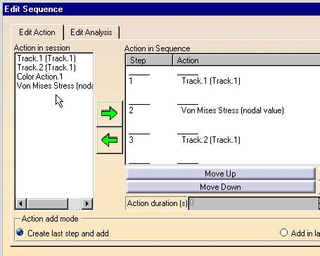
40 Page 40 Steps Number: To make the animation more or less fluent Speed For a smooth animation set the Number of steps parameter to its maximum value (20) and activate the Repeat play and reverse non stop button. 4. Click the Play forward button. Animation is resumed, with the new settings taken into account. 5. Click OK to exit the Animation application. The animation capability is also available for Frequency Solutions. DMU Navigator 1. Select Start -> Digital Mockup -> DMU Navigator from the toolbar and use the available Play a Simulation icon. OR 1. From any of the DMU workbenches (except DMU Engineering Analysis Review), select the Tools -> Simulation command. With the Play a Simulation functionality, you can animate the image. For more details on Publishing Tools, see DMU Navigator user's guide. Generated images are considered as DMU actions and can be integrated insides sequences (see command called Edit Sequence).
41 Page 41

42 Page 42 Cut Plane Analysis Cut plane analysis consists in visualizing results in a plane section through the structure. By dynamically changing the position and orientation of the cutting plane, you can rapidly analyze the results inside the system. This task shows how to use the Cut Plane Analysis capability. You can use the sample26.catanalysis document: you created a Stress Von Mises image. 1. Click the Cut Plane Analysis icon. The Cutting Plane automatically appears.

43 Page 43 The Cut Plane Analysis dialog box is displayed. The compass is automatically positioned on the part, with a Cutting Plane normal to its privileged direction. Note that if the compass is already positioned on the view, the normal of the compass is taken into account as the default normal of the cutting plane. 2. Handle the compass using the cursor and rotate or translate the Cutting Plane. For this, you will select an edge of the compass and drag the cursor. As you modify the plane position, results in the Cutting Plane are automatically updated.

44 Page Activate the View section Only option in the Cut Plane Analysis dialog box to see the section relatively to the position of the cutting plane. 4. De-activate the Show cutting plane option in the Cut Plane Analysis dialog box to see only the boundary of this cutting plane.
45 Page Click CLOSE in the Cut Plane Analysis dialog box to exit the Cut Plane application. The cut plane capability is also available for Frequency Solutions. All the existing images will be cut, if needed.

46 Page 46 Amplitude Modulation Amplitude Modulation consists in scaling the maximum displacement amplitude for visualizing a deformed mesh image. You can either choose a large scaling coefficient to zoom on the deformed geometry or a small coefficient to obtain a realistic visualization. This task shows how to use the Amplitude Modulation capability. You can use the sample26.catanalysis document: you created a Stress Von Mises image. 1. Click the Deformation Scale Factor icon in the bottom toolbar. The Deform Window dialog box is displayed. The deformed geometry is visualized with the default values of the following parameters: Deformed Coefficient: the scaling factor.
47 Page 47 Maximum Displacement: the value in mm of the maximum allowed displacement on the image. You can edit the Deform Window dialog box dialog box and set the parameters. The cursor further allows you to dynamically change the scale factor from None to Max. 2. Enter 100mm as Maximum Displacement new value in the Deform Window dialog box. The Magnification cursor is automatically set to Max. A new image is displayed with your settings taken into account. 3. Click OK to exit the Deform Window dialog box. The animation capability is also available for Frequency and Buckling Solutions.

48 Page 48 Extrema Detection Extrema Detection consists in localizing points where a results field is maximum or minimum. You can ask the program to detect either one or both global extrema and an arbitrary number of local extrema for your field. This task shows how to use the Extrema Detection capability. You can use the sample26.catanalysis document: you created a Stress Von Mises image. 1. Click the Search Image Extrema icon. The Extrema Creation dialog box is displayed.
49 Page 49 You can ask the program to detect given numbers of global (on the whole part) and/or local (relatively to neighbor mesh elements) extrema at most, by setting the Global and Local switches. If you activate the Global option, you will launch the detection of the minimum and maximum global extrema. Global means that the system will detect all the entities which have a value equal to the Minimum or Maximum value. If you activate the Local option, you will launch the detection of the minimum and maximum local extrema. Local means that the system will search all the entities which are related to the Minimum or Maximum value compared to the two-levelled neighboring entities. 3. Click OK to exit the dialog box. A new image corresponding to the default settings is displayed, with two arrow boxes locating the points of absolute extremum for the current field and containing information about the detected value. The Extrema object set containing the two Global Extrema appears under the current Image object in the specification tree.


50 Page Double click the Extrema object set in the specification tree. The Extrema Creation dialog box appears. You can modify the objects set by setting the Global and Local switches. 5. Set the Global switch to off and the Local switch to on. The boxes locating the global extrema disappear, and symbols locating the local extrema are visualized. The Extrema objects set in the specification tree now contains, in addition to the two Global Extrema objects, as many Local Extremum (Maximum or Minimum) objects as you have required.

51 Page Double-click one of the Local Extremum objects in the specification tree. The Image Extremum Editor dialog box is displayed. 7. Set the Show Label option to on and then OK, in the Image Extremum Editor dialog box. A new arrow box is visualized, locating the position of the corresponding point and containing information about the detected value. 8. Click OK to exit the Image Extremum Editor dialog box. The extrema detection capability is also available for images obtained under Frequency and Buckling Solutions.

52 Page 52 Manipulating the Color Palette The von Mises stresses, the Displacements, the Precision, the Principal Stress distributions are employed along with a Color Palette. This task shows how to edit the Palette on Von Mises display. You can use the sample26.catanalysis document: you created a Stress Von Mises image. 1. Click on the color palette once. The color palette is now active (the part viewer is deactivated and the part is shaded) and can be manipulated: either moved using the middle mouse button or zoomed using the middle mouse button and then the left mouse button. Move the palette Use the middle mouse button and drag the palette to the desired location.

53 Page 53 Zoom In / Zoom Out the palette Use the middle mouse button, then the left mouse button and zoom either in or out the palette to the desired size.
54 Page 54
55 Page 55 Information This task shows how to get information on one or more images and extrema you generated.. You can use the sample26.catanalysis document. You have to activate an image. 1. Click the Information icon. 2. Select the Von Mises Stress image in the specification tree. The Information dialog box appears.

56 Page Click Close in the Information dialog box. 4. Create extrema. For more details, please refer to Extrema Detection. 5. Click the Information icon. 6. Click Close in the Information dialog box.


57 Page 57 Images Layout This task shows how to tile layout images. Generated images corresponding to analysis results are superimposed into one image that cannot be properly visualized. You can tile these superimposed images into as many layout images on the 3D view. You can use the sample13.catanalysis document from the samples directory for this task. Make sure at least one image was created and activated on the part. 1. Click the Images Layout icon. The Images Layout dialog box appears. 2. Select the axis along which you will tile the images, in the Images Layout dialog box.

58 Page Click OK in the Images Layout dialog box. The images are tiled along the Y axis. Select the Untile option in the Image Layout dialog box if you want to have the images superimposed again. You can animate one or more of these images, if desired. Be careful: the cutting plane will cut all the images.

59 Page 59 Workbench Description This section contains the description of the icons and menus which are specific to the DMU Engineering Analysis Review workbench. You can click the sensitive areas on this image to see related documentation. Menu Bar Toolbar

60 Page 60 Menu Bar The DMU - Analysis Engineering Review menu bar contains the following commands: Tools Menu For... See... Basic Analysis Report Basic Analysis Report Animate an Analysis Image Image Animation: Cut Plane Analysis Cut Plane Analysis Deformation Scale Factor Amplitude Modulation Image Extrema Extrema Detection Image Layout Images Layout
61 Page 61 Toolbar The Analysis Tools and Results toolbars contain the following tools to manage results: See Generating Images See Reporting See Animating Images See Cut Plane Analysis See Amplitude Modulation See Extrema Detection See Images Layout
62 Page 62 Index A amplitude modulation animation image C color palette cut plane analysis E extrema G generation image I image animation generation layout
63 Page 63 L layout image R report
DMU Engineering Analysis Review
 DMU Engineering Analysis Review Overview Conventions What's New? Getting Started Entering DMU Engineering Analysis Review Workbench Generating an Image Visualizing Extrema Generating a Basic Analysis Report
Getting Started. These tasks should take about 20 minutes to complete. Getting Started
 Getting Started Getting Started This tutorial will guide you step-by-step through your first ELFINI and Generative Part Structural Analysis session, allowing you to get acquainted with the product. You
Advanced Meshing Tools
 Page 1 Advanced Meshing Tools Preface Using This Guide More Information Conventions What's New? Getting Started Entering the Advanced Meshing Tools Workbench Defining the Surface Mesh Parameters Setting
Electrical 3D Design & Documentation
 Electrical 3D Design & Documentation Page 1 Overview Conventions User Tasks Using Electrical 3D Design & Documentation Entering the Electrical Assembly Design Workbench Entering the Electrical Part Design
Tolerance Analysis of Deformable Assembly
 Tolerance Analysis of Deformable Assembly Overview Conventions What's New? Getting Started Entering the Workbench Creating a New Analysis Importing the Assembly Definition Computing a Tolerance Analysis
DMU Space Engineering Assistant User Guide
 Page 1 DMU Space Engineering Assistant User Guide Overview Conventions What's New? Getting Started User Tasks Setting Up Your Session Running a Interference Workbench Description DMU Space Engineering
DMU Space Engineering Assistant User Guide
 DMU Space Engineering Assistant User Guide Overview Conventions What's New? Getting Started User Tasks Setting Up Your Session Running an Interference Analysis Workbench Description DMU Space Engineering
DMU Fitting Simulator
 Page 1 DMU Fitting Simulator Preface Using This Guide More Information Conventions What's New? Getting Started Using Tracks Starting a Session Recording a Track Using Automatic Path Finder Using the Smooth
Electrical Harness Flattening
 Electrical Harness Flattening Overview Conventions What's New? Getting Started Accessing the Electrical Harness Flattening Workbench Defining the Harness Flattening Parameters Extracting Data Flattening
Electrical Harness Installation
 Electrical Harness Installation Page 1 Overview Conventions What's New? Getting Started Entering the Workbench Setting Up the Options Creating a Bundle Segment Document Creating Construction Points Defining
DMU Space Analysis Version 5 Release 13. DMU Space Analysis
 Page 1 DMU Space Analysis Preface Using This Guide More Information Conventions What's New? Getting Started Setting Up Your Session Measuring Minimum Distances Sectioning Detecting Clashes Measuring Between
Equipment Support Structures
 Page 1 Equipment Support Structures Preface Using This Guide Where to Find More Information Conventions What's New? Getting Started Setting Up Your Session Creating a Simple Structural Frame Creating Non-uniform
Generative Part Structural Analysis Fundamentals
 CATIA V5 Training Foils Generative Part Structural Analysis Fundamentals Version 5 Release 19 September 2008 EDU_CAT_EN_GPF_FI_V5R19 About this course Objectives of the course Upon completion of this course
FEA BENDING, TORSION, TENSION, and SHEAR TUTORIAL in CATIA
 1 FEA BENDING, TORSION, TENSION, and SHEAR TUTORIAL in CATIA This tutorial shows the basics of a solid bending, torsional, tension, and shear FEA (Finite Elemental Analysis) model in CATIA. Torsion - page
Product Synthesis. DMU - Engineering Analysis Review 2 (ANR) CATIA V5R18
 CATIA V5R18") Product Synthesis DMU - Engineering Analysis Review 2 (ANR) CATIA V5R18 Product Synthesis DMU - Engineering Analysis Review Provide an easy-to-use capability to visualize and perform DMU reviews of Engineering
Product Synthesis DMU - Engineering Analysis Review 2 (ANR) CATIA V5R18 Product Synthesis DMU - Engineering Analysis Review Provide an easy-to-use capability to visualize and perform DMU reviews of Engineering
Equipment Support Structures
 Equipment Support Structures Overview Conventions What's New? Getting Started Setting Up Your Session Creating a Simple Structural Frame Creating Non-uniform Columns Creating Plates with Openings Bracing
Fastening Review Overview Basic Tasks DMU Fastening Review Interoperability Workbench Description Customizing Index
 Fastening Review Overview Conventions Basic Tasks Displaying Joined Parts in a Balloon Running the Fastening Rules Analysis Reporting Creating Structural Reports Creating Flat Reports DMU Fastening Review
Circuit Board Design Version 5 Release 13. Circuit Board Design
 Circuit Board Design Page 1 Overview Conventions What's New? Getting Started Accessing the Circuit Board Workbench Creating a Board Pocket and Holes Constraint Area Exporting Data Importing Data User Tasks
Electrical Wire Routing
 Electrical Wire Routing Page 1 Overview Conventions What's New? Getting Started Accessing the Workbench Creating the Bundle Selecting Systems with External Data Routing Wires from External Data User Tasks
NC Manufacturing Verification
 NC Manufacturing Verification Overview Conventions What's New? User Tasks Accessing NC Manufacturing Verification Comparing the Machined Stock Part and the Design Part Pick Point Analysis in Video Mode
Generative Part Structural Analysis Expert
 CATIA V5 Training Foils Generative Part Structural Analysis Expert Version 5 Release 19 September 2008 EDU_CAT_EN_GPE_FI_V5R19 About this course Objectives of the course Upon completion of this course
Product Structure Version 5 Release 13. Product Structure
 Product Structure Page 1 Site Map Preface Conventions What's New? Basic Tasks Entering the Product Structure Workbench Opening a CATProduct with a Progress Bar Selecting Products only Selecting Modes Inserting
DMU Optimizer Overview What's New? Getting Started User Tasks
 DMU Optimizer Overview Conventions What's New? Getting Started Starting a Session Generating a Silhouette Generating a Wrapping Generating a Thickness Generating an Offset Generating a Free Space User
NC Manufacturing Verification
 NC Manufacturing Verification Page 1 Preface Using This Guide Where to Find More Information Conventions What's New? User Tasks Accessing NC Manufacturing Verification Comparing the Machined Stock Part
Electrical Library Version 5 Release 13. Electrical Library
 Electrical Library Page 1 Overview Conventions What's New? Getting Started Entering the Electrical Part Design Workbench Defining a Single Insert Connector Defining a Cavity Connection Point Entering Electrical
Electrical System Functional Definition
 Electrical System Functional Definition Preface What's New? Getting Started Basic Tasks Advanced Tasks Workbench Description Customizing Glossary Index Dassault Systèmes 1994-2000. All rights reserved.
Prismatic Machining Overview What's New Getting Started User Tasks
 Prismatic Machining Overview Conventions What's New Getting Started Enter the Workbench Create a Pocketing Operation Replay the Toolpath Create a Profile Contouring Operation Create a Drilling Operation
ABAQUS for CATIA V5 Tutorials
 ABAQUS for CATIA V5 Tutorials AFC V2.5 Nader G. Zamani University of Windsor Shuvra Das University of Detroit Mercy SDC PUBLICATIONS Schroff Development Corporation www.schroff.com ABAQUS for CATIA V5,
Electrical System Functional Definition
 Electrical System Functional Definition Overview Conventions What's New? Getting Started Creating a New System Creating Equipment Creating Connectors Creating a Signal Connecting Saving Your System User
Lesson 6: Assembly Structural Analysis
 Lesson 6: Assembly Structural Analysis In this lesson you will learn different approaches to analyze the assembly using assembly analysis connection properties between assembly components. In addition
Structure Preliminary Layout
 Page 1 Structure Preliminary Layout Preface Using This Guide Where to Find More Information What's New? Getting Started Setting Up Your Session Defining the Hull Form Setting Up Your Grid Creating Molded
Structure Preliminary Layout
 Structure Preliminary Layout Overview Conventions What's New? Getting Started Setting Up Your Session Defining the Hull Form Setting Up Your Grid Creating Molded Forms Creating a Compartment Creating Boundaries
2: Static analysis of a plate
 2: Static analysis of a plate Topics covered Project description Using SolidWorks Simulation interface Linear static analysis with solid elements Finding reaction forces Controlling discretization errors
Preface. Version 5 Release 5. Mold Tooling Design
 Version 5 Release 5 Mold Tooling Design Preface Getting Started Basic Tasks Advanced Tasks Customization Workbench Description Glossary Index Preface The CATIA Version 5 Mold Tooling Design application
Exercise 2: Bike Frame Analysis
 Exercise 2: Bike Frame Analysis This exercise will analyze a new, innovative mountain bike frame design under structural loads. The objective is to determine the maximum stresses in the frame due to the
FreeStyle Shaper Optimizer & Profiler
 FreeStyle Shaper Optimizer & Profiler Page 1 Preface Using This Guide More Information What's New? Getting Started Starting the FreeStyle Workbench Creating a First Surface Editing the Surface Creating
Introduction And Overview ANSYS, Inc. All rights reserved. 1 ANSYS, Inc. Proprietary
 Introduction And Overview 2006 ANSYS, Inc. All rights reserved. 1 ANSYS, Inc. Proprietary The ANSYS Workbench represents more than a general purpose engineering tool. It provides a highly integrated engineering
BioIRC solutions. CFDVasc manual
 BioIRC solutions CFDVasc manual Main window of application is consisted from two parts: toolbar - which consist set of button for accessing variety of present functionalities image area area in which is
Elfini Solver Verification
 Page 1 Elfini Solver Verification Preface Using this Guide Where to Find More Information Conventions What's new User Tasks Static Analysis Cylindrical Roof Under its Own Weight Morley's Problem Twisted
Exercise 2: Bike Frame Analysis
 Exercise 2: Bike Frame Analysis This exercise will analyze a new, innovative mountain bike frame design under structural loads. The objective is to determine the maximum stresses in the frame due to the
Lesson: Static Stress Analysis of a Connecting Rod Assembly
 Lesson: Static Stress Analysis of a Connecting Rod Assembly In this tutorial we determine the effects of a 2,000 pound tensile load acting on a connecting rod assembly (consisting of the rod and two pins).
SDC. Engineering Analysis with COSMOSWorks. Paul M. Kurowski Ph.D., P.Eng. SolidWorks 2003 / COSMOSWorks 2003
 Engineering Analysis with COSMOSWorks SolidWorks 2003 / COSMOSWorks 2003 Paul M. Kurowski Ph.D., P.Eng. SDC PUBLICATIONS Design Generator, Inc. Schroff Development Corporation www.schroff.com www.schroff-europe.com
CHAPTER 8 FINITE ELEMENT ANALYSIS
 If you have any questions about this tutorial, feel free to contact Wenjin Tao (w.tao@mst.edu). CHAPTER 8 FINITE ELEMENT ANALYSIS Finite Element Analysis (FEA) is a practical application of the Finite
Systems Space Reservation
 Systems Space Reservation Preface Using This Guide What's New? Getting Started Enter the Workbench Create an Equipment Reservation Set Correct Working Units and Grid Changing the Current Axis Saving Documents
Exercise 1: Axle Structural Static Analysis
 Exercise 1: Axle Structural Static Analysis The purpose of this exercise is to cover the basic functionality of the Mechanical Toolbar (MTB) in the context of performing an actual analysis. Details of
Tutorial 1: Welded Frame - Problem Description
 Tutorial 1: Welded Frame - Problem Description Introduction In this first tutorial, we will analyse a simple frame: firstly as a welded frame, and secondly as a pin jointed truss. In each case, we will
Aerospace Sheetmetal Design
 Aerospace Sheetmetal Design Page 1 Overview Conventions What's New? Getting Started Entering the Aerospace SheetMetal Design Workbench Defining the Aerospace SheetMetal Parameters Creating a Web from a
ME Week 12 Piston Mechanical Event Simulation
 Introduction to Mechanical Event Simulation The purpose of this introduction to Mechanical Event Simulation (MES) project is to explorer the dynamic simulation environment of Autodesk Simulation. This
CATIA Electrical Space Reservation TABLE OF CONTENTS
 TABLE OF CONTENTS Introduction...1 Manual Format...2 Electrical Reservations...3 Equipment Reservations...5 Pathway Reservations...31 Advanced Reservations...49 Reservation Analysis...67 Clash...69 Sectioning...73
Post-Processing Static Results of a Space Satellite
 LESSON 7 Post-Processing Static Results of a Space Satellite 3.84+05 3.58+05 3.33+05 3.07+05 2.82+05 3.84+05 2.56+05 2.30+05 2.05+05 1.79+05 1.54+05 1.28+05 1.02+05 7.68+04 0. 5.12+04 Z Y X Objectives:
Photo Studio. Preface What`s New? Getting Started Basic Tasks Advanced Tasks Workbench Description Customizing Glossary Index
 Photo Studio Preface What`s New? Getting Started Basic Tasks Advanced Tasks Workbench Description Customizing Glossary Index Dassault Systèmes 1994-2000. All rights reserved. Preface Welcome to Version
Analysis Steps 1. Start Abaqus and choose to create a new model database
 Source: Online tutorials for ABAQUS Problem Description The two dimensional bridge structure, which consists of steel T sections (b=0.25, h=0.25, I=0.125, t f =t w =0.05), is simply supported at its lower
Static Stress Analysis
 Static Stress Analysis Determine stresses and displacements in a connecting rod assembly. Lesson: Static Stress Analysis of a Connecting Rod Assembly In this tutorial we determine the effects of a 2,000-pound
CATIA V5 FEA Tutorials Release 14
 CATIA V5 FEA Tutorials Release 14 Nader G. Zamani University of Windsor SDC PUBLICATIONS Schroff Development Corporation www.schroff.com www.schroff-europe.com CATIA V5 FEA Tutorials 2-1 Chapter 2 Analysis
FEM Surface. Preface Getting Started Basic Tasks Glossary Index TOC. Dassault Systèmes All rights reserved.
 TOC FEM Surface Preface Getting Started Basic Tasks Glossary Index Dassault Systèmes 1994-99. All rights reserved. file:////moyenne/users/cma/fmsdoccxr5/fmsenglish/fmsug.doc/src/fmsugtoc.htm [09/26/2000
Piping Design. Site Map Preface Getting Started Basic Tasks Advanced Tasks Customizing Workbench Description Index
 Piping Design Site Map Preface Getting Started Basic Tasks Advanced Tasks Customizing Workbench Description Index Dassault Systèmes 1994-2001. All rights reserved. Site Map Piping Design member member
Human Posture Analysis
 Human Posture Analysis Page 1 Preface Using This Guide Where to Find More Information Conventions What's New? Getting Started Creating a Manikin User Tasks Using the Posture Editor Segments Degree of Freedom
Learning Module 8 Shape Optimization
 Learning Module 8 Shape Optimization What is a Learning Module? Title Page Guide A Learning Module (LM) is a structured, concise, and self-sufficient learning resource. An LM provides the learner with
Knowledge Expert Overview What's New? Getting Started Basic Tasks Advanced Tasks Reference
 Knowledge Expert Overview Conventions What's New? Getting Started Creating an Expert Check Creating an Expert Rule Basic Tasks About RuleBases Storing a Rule Base in a Catalog Using a Rule Base Stored
FreeStyle Shaper & Optimizer
 FreeStyle Shaper & Optimizer Preface What's New Getting Started Basic Tasks Advanced Tasks Workbench Description Customizing Glossary Index Dassault Systèmes 1994-99. All rights reserved. Preface CATIA
Human Posture Analysis
 Human Posture Analysis Overview Conventions What's New? Getting Started Creating a Manikin User Tasks Using the Posture Editor Selecting or Editing the DOF (Degree of Freedom) Displaying and Editing Angular
GMS 10.0 Tutorial Stratigraphy Modeling TIN Surfaces Introduction to the TIN (Triangulated Irregular Network) surface object
 surface object") v. 10.0 GMS 10.0 Tutorial Stratigraphy Modeling TIN Surfaces Introduction to the TIN (Triangulated Irregular Network) surface object Objectives Learn to create, read, alter, and manage TIN data from within
v. 10.0 GMS 10.0 Tutorial Stratigraphy Modeling TIN Surfaces Introduction to the TIN (Triangulated Irregular Network) surface object Objectives Learn to create, read, alter, and manage TIN data from within
GMS 8.2 Tutorial Stratigraphy Modeling TIN Surfaces Introduction to the TIN (triangulated irregular network) surface object
 surface object") v. 8.2 GMS 8.2 Tutorial Introduction to the TIN (triangulated irregular network) surface object Objectives Learn to create, read, alter and manage TIN data from within GMS. Prerequisite Tutorials None
v. 8.2 GMS 8.2 Tutorial Introduction to the TIN (triangulated irregular network) surface object Objectives Learn to create, read, alter and manage TIN data from within GMS. Prerequisite Tutorials None
LMS Virtual.Lab Durability
 LMS Virtual.Lab Durability Durability Step by Step Training Handouts Rev 9-SL1 LMS Virtual.Lab Durability Contents Contents... 3 Introduction... 4 Start LMS Virtual.Lab for the first time... 6 Exercise
Appendix B: Creating and Analyzing a Simple Model in Abaqus/CAE
 Getting Started with Abaqus: Interactive Edition Appendix B: Creating and Analyzing a Simple Model in Abaqus/CAE The following section is a basic tutorial for the experienced Abaqus user. It leads you
Tutorial: Simulating a 3D Check Valve Using Dynamic Mesh 6DOF Model And Diffusion Smoothing
 Tutorial: Simulating a 3D Check Valve Using Dynamic Mesh 6DOF Model And Diffusion Smoothing Introduction The purpose of this tutorial is to demonstrate how to simulate a ball check valve with small displacement
ICS Tutorials: Basic Operations
 ICS Tutorials: Basic Operations This tutorial introduces the basic components of Builder Xcessory. For more detailed information, see the Builder Xcessory Reference Manual. This book is directly accessible
Getting Started. The main tasks described in this section are the following:
 Getting Started Getting Started Before getting into the detailed instructions for using Interactive Drafting workbench, the following tutorial aims at giving you a feel of what you can do with the product.
v Stratigraphy Modeling TIN Surfaces GMS 10.3 Tutorial Introduction to the TIN (Triangulated Irregular Network) surface object
 surface object") v. 10.3 GMS 10.3 Tutorial Stratigraphy Modeling TIN Surfaces Introduction to the TIN (Triangulated Irregular Network) surface object Objectives Learn to create, read, alter, and manage TIN data from within
v. 10.3 GMS 10.3 Tutorial Stratigraphy Modeling TIN Surfaces Introduction to the TIN (Triangulated Irregular Network) surface object Objectives Learn to create, read, alter, and manage TIN data from within
전산응용설계 (Computer Aided Design)
") 전산응용설계 (Computer Aided Design) CATIA (Computer Aided Three dimensional Interactive Application) 기계자동차공학부자동차공학전공 Chapter 3. CATIA 기초 학습내용 : 객체선택 (Selecting Objects) 객체감추기와보이기 (Hiding and Showing objects)
전산응용설계 (Computer Aided Design) CATIA (Computer Aided Three dimensional Interactive Application) 기계자동차공학부자동차공학전공 Chapter 3. CATIA 기초 학습내용 : 객체선택 (Selecting Objects) 객체감추기와보이기 (Hiding and Showing objects)
Compartment and Access
 Compartment and Access Page 1 Preface Using This Guide What's New? Getting Started Entering the Workbench Set Correct Working Units and Grid Saving Documents User Tasks Creating/Modifying Wall Systems
Autodesk Moldflow Insight AMI Getting Started Tutorial
 Autodesk Moldflow Insight 2012 AMI Getting Started Tutorial Revision 1, 30 March 2012. This document contains Autodesk and third-party software license agreements/notices and/or additional terms and conditions
CATIA V5 Analysis. CATIA V5 Training Foils. CATIA V5 Analysis. Copyright DASSAULT SYSTEMES 1. Student Notes:
 CATIA V5 Training Foils CATIA V5 Analysis Version 5 Release 19 January 2009 EDU_CAT_EN_V5A_FF_V5R19 1 Lesson 1: Introduction to Finite Element Analysis About this Course Introduction CATIA is a robust
Tekla Structures Analysis Guide. Product version 21.0 March Tekla Corporation
 Tekla Structures Analysis Guide Product version 21.0 March 2015 2015 Tekla Corporation Contents 1 Getting started with analysis... 7 1.1 What is an analysis model... 7 Analysis model objects...9 1.2 About
Training Guide TopSolid Fea
 Training Guide i 2012, Missler Software. 7, Rue du Bois Sauvage F-91055 Evry, FRANCE Web: http://www.topsolid.com E-mail: info@topsolid.com All rights reserved. This information is subject to change without
Lesson: Adjust the Length of a Tuning Fork to Achieve the Target Pitch
 Lesson: Adjust the Length of a Tuning Fork to Achieve the Target Pitch In this tutorial, we determine the frequency (musical pitch) of the first fundamental vibration mode of a tuning fork. We then adjust
Compartment and Access
 Compartment and Access Preface Using This Guide What's New? Getting Started Entering the Workbench Set Correct Working Units and Grid Saving Documents User Tasks Creating/Modifying Wall Systems Building
Post Processing of Displacement Results
 WORKSHOP 16 Post Processing of Displacement Results Objectives: Examine the deformation of the MSC.Nastran model to evaluate the validity of the assumptions made in the creation of the mesh density and
Tutorial. How to use the Visualization module
 Page i Preface The purpose of this tutorial aims to describe certain visualization techniques in BRIGADE/Plus to facilitate and improve the users post-processing procedure. Page ii Contents 1. OVERVIEW...
Abaqus/CAE Axisymmetric Tutorial (Version 2016)
") Abaqus/CAE Axisymmetric Tutorial (Version 2016) Problem Description A round bar with tapered diameter has a total load of 1000 N applied to its top face. The bottom of the bar is completely fixed. Determine
Abaqus/CAE Axisymmetric Tutorial (Version 2016) Problem Description A round bar with tapered diameter has a total load of 1000 N applied to its top face. The bottom of the bar is completely fixed. Determine
Finite Element Analysis Using Creo Simulate 4.0
 Introduction to Finite Element Analysis Using Creo Simulate 4.0 Randy H. Shih SDC PUBLICATIONS Better Textbooks. Lower Prices. www.sdcpublications.com Powered by TCPDF (www.tcpdf.org) Visit the following
November c Fluent Inc. November 8,
 MIXSIM 2.1 Tutorial November 2006 c Fluent Inc. November 8, 2006 1 Copyright c 2006 by Fluent Inc. All Rights Reserved. No part of this document may be reproduced or otherwise used in any form without
Quarter Symmetry Tank Stress (Draft 4 Oct 24 06)
") Quarter Symmetry Tank Stress (Draft 4 Oct 24 06) Introduction You need to carry out the stress analysis of an outdoor water tank. Since it has quarter symmetry you start by building only one-fourth of
Quarter Symmetry Tank Stress (Draft 4 Oct 24 06) Introduction You need to carry out the stress analysis of an outdoor water tank. Since it has quarter symmetry you start by building only one-fourth of
Spur Gears Static Stress Analysis with Linear Material Models
 Exercise A Spur Gears Static Stress Analysis with Linear Material Models Beam and Brick Elements Objective: Geometry: Determine the stress distribution in the spur gears when a moment of 93.75 in-lb is
POST-PROCESSING A RATCHET WHEEL
 A POST-PROCESS CASE STUDY POST-PROCESSING A RATCHET WHEEL The objective of this case study is to run a post process analysis of a steel ratchet wheel subjected to a set of forces. We will observe the stresses
Introduction to Engineering Analysis
 Chapter 1 Introduction to Engineering Analysis This chapter introduces you to the Stress Analysis and Dynamic Simulation environments. You learn how digital prototyping can be used to simulate your designs
FINITE ELEMENT ANALYSIS OF A PLANAR TRUSS
 Problem Description: FINITE ELEMENT ANALYSIS OF A PLANAR TRUSS Instructor: Professor James Sherwood Revised: Dimitri Soteropoulos Programs Utilized: Abaqus/CAE 6.11-2 This tutorial explains how to build
TABLE OF CONTENTS WHAT IS ADVANCE DESIGN? INSTALLING ADVANCE DESIGN... 8 System requirements... 8 Advance Design installation...
 Starting Guide 2019 TABLE OF CONTENTS INTRODUCTION... 5 Welcome to Advance Design... 5 About this guide... 6 Where to find information?... 6 Contacting technical support... 6 WHAT IS ADVANCE DESIGN?...
Finite Element Analysis Using NEi Nastran
 Appendix B Finite Element Analysis Using NEi Nastran B.1 INTRODUCTION NEi Nastran is engineering analysis and simulation software developed by Noran Engineering, Inc. NEi Nastran is a general purpose finite
Creating and Analyzing a Simple Model in Abaqus/CAE
 Appendix B: Creating and Analyzing a Simple Model in Abaqus/CAE The following section is a basic tutorial for the experienced Abaqus user. It leads you through the Abaqus/CAE modeling process by visiting
1 awea.com.m y
 1 www.mawea.com.m y 2 www.mawea.com.m y Announcement (1.0) (1.1) LUM END of Support The support of LUM licensing technology was end on December 31 st 2013. This technology had been replaced by DSLS which
Prerequisites: This tutorial assumes that you are familiar with the menu structure in FLUENT, and that you have solved Tutorial 1.
 Tutorial 22. Postprocessing Introduction: In this tutorial, the postprocessing capabilities of FLUENT are demonstrated for a 3D laminar flow involving conjugate heat transfer. The flow is over a rectangular
Getting Started with ShowcaseChapter1:
 Chapter 1 Getting Started with ShowcaseChapter1: In this chapter, you learn the purpose of Autodesk Showcase, about its interface, and how to import geometry and adjust imported geometry. Objectives After
Importing Results using a Results Template
 LESSON 15 Importing Results using a Results Template Objectives: Write a custom nodal and displacement results template. Import a Patran 2.5 Neutral File model. Import a Patran 2.5 Results File. Perform
Engine Gasket Model Instructions
 SOL 600 Engine Gasket Model Instructions Demonstrated:! Set up the Model Database! 3D Model Import from a MSC.Nastran BDF! Creation of Groups from Element Properties! Complete the Material Models! Import
SOLIDWORKS: Lesson 1 - Basics and Modeling. Introduction to Robotics
 SOLIDWORKS: Lesson 1 - Basics and Modeling Fundamentals Introduction to Robotics SolidWorks SolidWorks is a 3D solid modeling package which allows users to develop full solid models in a simulated environment
Frame Analysis Using Visual Analysis
 Frame Analysis Using Visual Analysis 1. The software is available at the Open Access Labs (OAL) and the Virtual OAL at http://voal.tamu.edu in Programs under the Windows Start menu. The software can also
Introduction to CFX. Workshop 2. Transonic Flow Over a NACA 0012 Airfoil. WS2-1. ANSYS, Inc. Proprietary 2009 ANSYS, Inc. All rights reserved.
 Workshop 2 Transonic Flow Over a NACA 0012 Airfoil. Introduction to CFX WS2-1 Goals The purpose of this tutorial is to introduce the user to modelling flow in high speed external aerodynamic applications.
Surface Modeling With TINs
 GMS TUTORIALS The TIN module in GMS is used for general-purpose surface modeling. TIN is an acronym for Triangulated Irregular Network. TINs are formed by connecting a set of xyz points with edges to form
CECOS University Department of Electrical Engineering. Wave Propagation and Antennas LAB # 1
 CECOS University Department of Electrical Engineering Wave Propagation and Antennas LAB # 1 Introduction to HFSS 3D Modeling, Properties, Commands & Attributes Lab Instructor: Amjad Iqbal 1. What is HFSS?