DATA LOGGER (Version V1.3)
|
|
|
- Sheila Fleming
- 5 years ago
- Views:
Transcription


1 WYLER AG Im Hölderli CH-8405 WINTERTHUR Switzerland Tel (0) Fax (0) Homepage: Operating instructions DATA LOGGER (Version V1.3)
2 Table of contents Table of contents... 2 Overview System description Parameter Data connections Software installation System prerequisites Installation Driver installation Logger hardware Sensor connection SIM card Changing batteries Status LED Activate logger Activate/deactivate Bluetooth Activate/deactivate GSM Software Starting the software Projects Opening a project New project Copying a project Software settings FTP download Searching for logger Firmware update Context menu Adding an element Deleting an element Online connection Connection settings Programming from settings file Data query Deleting measured data file Ftp import Replace element Excel Logger settings Overview Measured data Measuring Logger Recording Monitoring Bluetooth GSM Message recipients Server Settings files Chart presentation Zoom function Change scale Printing Microsoft Excel Export


3 Overview 1.1 System description The Data-Safe800 logger was especially designed for harsh environments and long measuring periods and distinguishes itself due to its modular design. Due to its very small dimensions and the integrated battery, the device can quickly and easily be used for various autonomous measuring and monitoring applications. In the GSM design, the data is automatically transferred to the measurement center via Internet. Thanks to its low power consumption, the Data-Safe800 logger can reliably measure, record, and monitor for an extended period. Automatic data export to an FTP server Automatic data import from the server to the measurement center (PC) Various sensor modules for up to 4 channels Low power consumption for long measurement applications Short-distance radio for the connection from the PC to the on-site logger Remote maintenance by means of GSM connection SMS-messages such as exceeding limit values Simple configuration software Temperature range Small, robust housing (IP66) Multiple attachment possibilities on the back Optional solar power supply for maintenance-free operation External battery pack for long autonomous measuring periods Sensor modules for: - Current/voltage - Digital inputs - Level sensors - Temperature sensors - Extensometers and inclination sensors - Meteorological sensors (wind, temp./humidity, pressure) - Customer-specific sensor modules are possible Logger module - Memory for 80,000 measured values - Up to 3 years of battery life (depending upon the operating mode) - Replaceable battery pack - External power supply (e.g. solar, battery pack) - Sensor power supply up to 25V through the logger Interface: - Bluetooth or short-distance radio 860MHz - GSM/GPRS for remote access and FTP (can be combined with Bluetooth or radio) Software - Every channel can be configured individually - Measuring intervals and measuring periods are adjustable Time window for GSM access is adjustable - Limit value monitoring for every channel - Battery warning via SMS - Automatic data transfer to the FTP-server - Numerous additional functions
 See sensor module specifications Data storage, total Data storage per channel Dynamic 1) 80,000 Up to")
 Measuring periods per day with various measuring intervals FTP transmissions or GSM time window for remote access Battery life Sensor power supply (adjustable) Max.")
4 Specifications: Parameter Conditions Unit Precision See sensor module specifications Resolution 14 Bit 3) See sensor module specifications Data storage, total Data storage per channel Dynamic 1) 80,000 Up to 80,000 Measuring interval Max. 1 (adjustable) Measuring periods per day with various measuring intervals FTP transmissions or GSM time window for remote access Battery life Sensor power supply (adjustable) Max. load of the sensor power supply Logger module mass Ø x L with GSM antenna Operating temperature Storage temperature Operating temperature with GSM IP degree of protection / conformity Min. 1 Number 2 Number Interval Number Duration 2) Min. Max. Per channel Total Max. Max. Max Max Ø 41 x 100 Ø 41 x Measured values Per minute Per day Per day Hours Per day Minutes Years V ma mm mm C 66 (67) IP 1) The total number of measured values is dynamically distributed to the number of active channels 1) Depends upon sensor module, sensor type, and measurement interval, as well as GSM switch on time 2) Module-dependent 31mm 139mm 103mm 39mm

 SMS mobile phone")


5 1.2 Data connections PC, notebook Data-Safe Manager Bluetooth or 860MHz FTP server server (being prepared) SMS mobile phone Modem (landline/gsm) GSM SMS / GPRS Data-Safe Manager PC, notebook GPRS (mobile internet) Data-Safe800 logger Modem connection (landline/gsm) SMS Internet FTP / server Mobile phone SMS Measurement center

6 2 Software installation 2.1 System prerequisites The following system prerequisites must be met for the installation of the Data-Safe800 software: At least 512MB RAM 35MB free memory capacity on the hard drive Microsoft.Net 3.5 Microsoft Windows XP SP2, Vista, Windows 7/32Bit Internet connection 2.2 Installation Start the installation by double clicking on the setup file. Your system will be checked. If Microsoft.Net 3.5 is not installed on your system, the following message will appear: In this case, please install Microsoft.Net 3.5 first and start restart the installation. The Microsoft.Net 3.5 installation (dotnetfx35.exe) is also included on the provided data carrier
![Click on [Continue] to install the program.](/docs-images/90/103047046/images/7-0.jpg "When installation is finished, click on")
![[Finish].](/docs-images/90/103047046/images/7-1.jpg "The software has been successfully")
7 Click on [Continue] to install the program. When installation is finished, click on [Finish]. The software has been successfully installed and can now be used

8 2.3 Driver installation To use the Data-Safe800 logger, a radio interface must first be set up. If you have already connected the radio interface to your computer, disconnect it before beginning with the installation. Double click on the file CDM exe in order to install the driver. The driver will now be installed automatically. After the completion of installation, you can connect the radio interface to your computer

 blue 4 Rs485 (B) black 5 GND (0V) gray 6 Sensor feed 0.25V pink 3.")

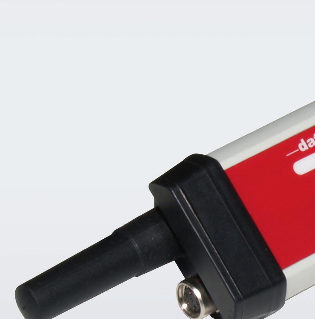
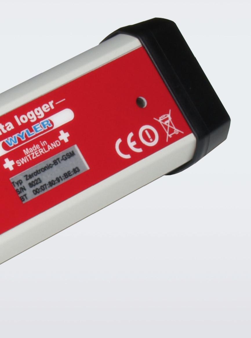
9 3 Logger hardware The Data-Safe800 logger is available in various versions. The pin assignment can therefore vary between the different models. For models without GSM equipment, you can skip Chapter Sensor connection The sensors are connected to the logger by means of a 6-pole plug. Please use the provided connection cable. Pin assignment for Zerotronic and Zeromatic: 1 Rs485 (A) brown 2 External logger feed 5..30VDC white 3 External logger feed (GND) blue 4 Rs485 (B) black 5 GND (0V) gray 6 Sensor feed 0.25V pink 3.2 SIM card The SIM card is located in the battery compartment of the device. The battery compartment must first be opened so that the SIM card can be inserted. To do this, loosen the attachment screw on the front of the device and remove the rubber cap. The SIM card can now be carefully inserted without applying force. Please ensure that the contact surfaces are in the correct position. SIM
.")
10 For a correct function of the card in the logger, you must deactivate the PIN-code on the SIM card. We recommend using a mobile phone to do this. 3.3 Changing batteries Before changing batteries, you must ensure that the radio module and GSM module are switched off (see and 3.5.2). Now, open the rubber cap of the battery compartment and carefully pull the battery out of the housing. Insert the new battery into the battery compartment until it stops within 2 minutes. Polarity is irrelevant in this case. Now, replace the battery cover on the device and tighten the attachment screw firmly. In order to ensure the watertightness of the housing, the seal surfaces must be free of contaminants. Now, create a connection to the logger and set the battery capacity to 100% (see ). 3.4 Status LED The logger has a status display in the form of a green LED on the logger front. The various operating conditions are displayed as follows: LED Operating condition Power Connection possibility consumption off Logger is inactive 1 minimal none flashing Bluetooth is active 2 low Bluetooth blinking 1s 1) Logging onto the GSM network 2) SMS sent, FTP data transmission 9 very high 9 very high none none on 1) There is a Bluetooth connection 2) Logger logged onto the GSM network 7 high 5 medium - modem


11 3.5 Activate logger The Data-Safe800 logger is equipped with an internal switch, which can be activated with a magnet. The magnetic switch is located near the green status LED of the logger. An activation magnet is installed in the handle of the battery tool, with which you can activate the logger at any time. Magnetic switch Battery tool Activation magnet Either the Bluetooth module or the GSM module, if applicable, can be switched on or off with the magnetic switch Activate/deactivate Bluetooth Activate the switched off Bluetooth module by holding the activation magnet on the logger for approx. 1 sec. The LED illuminates briefly. Deactivate the Bluetooth module in the same manner. 1 second Activate/deactivate GSM Activate the switched off GSM module by holding the activation magnet on the logger until the LED begins to blink (approx. 5 sec). Deactivate the GSM module in the same manner

12 The GSM module can only be deactivated when the LED-display illuminates constantly meaning after the GSM module has logged onto the network. If the network logon fails, the GSM is automatically switched off. The GSM module can also be activated with the Bluetooth module activated. >5 seconds


13 4 Software 4.1 Starting the software After starting, the software either changes directly to a project presentation or you will be asked to open a project. If no project exists, click on [Cancel] and then create a new project (see 4.2.2) Open project Project presentation


14 4.2 Projects The logger is managed by means of projects. Here, all of the required loggers are entered into a project. The loggers are then visible in a tree structure. You can add, delete, or move loggers. For greater clarity, the loggers can be combined into groups and subgroups. When you click on a group, a table with the information of all loggers in this group is displayed on the right side of the screen. A B C D E F G H I J A Operating condition of the logger Green dot for OK Red dot for exceeded limit value Stop for no data recording B C D E Data until States until what time measured data exists on your PC-drive Logger Designation of the logger Series number Logger messages Messages of the logger are entered in this field: Balance warning (for GSM with prepaid card) Battery level <30%
 Signal Reception quality during the last dial-up to the GSM network.")
15 Battery level <10% F G H I J GIS Only valid for card software (option) Info Here, information can be stored for each logger. For this, click on the field and then enter an information text. Balance Current balance when using a prepaid SIM card (only for GSM logger) Signal Reception quality during the last dial-up to the GSM network. Signal greater than -85dBm good reception quality Signal less than -95dBm poor reception quality Temperature Internal logger temperature (accuracy ± 2 C) The contents of the columns refer to the time of the last connection with the logger or the last Ftp data import. When a logger is clicked on, the measured data is graphically displayed on the right side of the screen (see 4.9)
16 4.2.1 Opening a project Projects are saved in *.prj files. Click on a project file and then click on [Open] to open an existing project New project Create new projects to manage your logger. A new folder is created with the necessary directory structure and all project files

17 A project has the following directories and files: Project directory Logger settings Data Project files Please do not make any changes to the directory structures or the project files! Copying a project Create a copy of a project in a new directory. You can create the copy of the project with or without the measured data. A new folder is created with the necessary directory structure and a copy of all project and data files


18 Editing a settings file You can save all of the settings of a logger in a settings file (see ) These settings files can be displayed and processed here without creating a connection with the logger. For this, select a settings file and click on [Open]


19 You can now view and change the settings. Click on Save the individual settings possibilities can be found in Chapter 4.8. to save all changes. A description of 4.3 Software settings You can define basic settings of the software here. Connection settings: After you have installed and connected the Bluetooth module, you must set the correct COM-port here. If a GSM modem or an analog modem is additionally used, you must also set the appropriate COM port here. Bluetooth external Stick Server settings: Please enter the access data for your FTP server here. You can set the software so that all existing measured data is automatically called up from the server with each program start. General settings: Lock the tree structure or the context menu in the main screen. 4.4 FTP download Click here in order to download the measured data of all loggers in the project from the FTP server. Here, it is checked for each logger whether measured data exists on the server. Existing data is downloaded and stored locally in a measured data file. If a file exists, the new data is attached to the existing file


20 Server: ftp.server.ch/logger 4.5 Searching for logger With this function, you can search for a logger in the project or in your environment via Bluetooth. Here, you can search for a certain logger in the project. The search is performed by means of the Bluetooth address or serial number. Here, you can search for all active loggers in your environment via Bluetooth. Please note that this function is not available with the Bluetooth stick

21 4.6 Firmware update You can update the firmware (internal logger software) by uploading a firmware file (*.bin) to your logger. This function can be applied to individual loggers as well as to groups of loggers. Before using this function, please ensure that all loggers are activated. Now, click on a logger or a group and then on Update. All loggers are called up one after the other and programmed with the new firmware. Please note that the appropriate firmware version must be loaded for each logger type. Therefore, a firmware update can only be used with groups with the same logger types. If the program file does not match the logger type, no firmware update will be performed. 4.7 Context menu You can reach the context menu by first highlighting a logger or a group in the tree structure with the right mouse button and then opening the context menu by clicking on it with the left mouse button. Elements (logger, groups, etc.) can be added or removed by means of the context menu. It is also used for all connecting, programming, and data query functions
 and open the context menu.")


22 4.7.1 Adding an element Click on a group (group is marked orange) and open the context menu. Now, select the element that you want to add to this group Adding a logger You can add a logger to a group by selecting the element logger in the context menu. Then, make the necessary connection settings. The connection settings can also be changed later (see 4.7.4)
")
23 Enter the Bluetooth address of the logger in the field BT Adr. and click on Save Adding a manager Add a manager to a group by selecting the element manager in the context menu. Then, make the necessary connection settings. The connection settings can also be edited later (see 4.7.1). Enter the Bluetooth address of the manager in the field BT Adr. and click on Save Adding a group You can add a subgroup to a group by selecting the element group in the context menu
 and open the context menu with the right mouse button. Then, select delete element.")
24 Enter the group designation now and click on Save. You can edit the group designation at any time by double clicking on the group name Deleting an element Mark an element (group, subgroup, or logger) and open the context menu with the right mouse button. Then, select delete element. This function can be applied to individual devices and groups. Deleting entire group:

25 Please note that all subgroups within the selected group will also be deleted. Deleting individual devices:

26 4.7.3 Online connection You can set up an online connection with a logger three different ways. Connection via Bluetooth Remote connection via GSM modem Remote connection via analog modem Ensure that the desired communication device is connected to your PC. Mark a logger and select the respective connection type in the context menu. The connection will be set up automatically. You can also set up the Bluetooth connection with a double click on a logger


27 4.7.4 Connection settings Mark a logger and select connection settings in the context menu. You can now enter a Bluetooth address or a GSM number. Click on save in order to save the settings

28 4.7.5 Programming from settings file You can program an individual logger or a logger group with the settings from a settings file. Here, the logger is completely reprogrammed except for the logger designation and the location. This function may only be used with groups with the same logger type. Programming with the wrong settings files can lead to malfunctions Data query A data query can include individual loggers or all loggers of a group. For this, mark a logger or a group and select the desired connection type in the context menu under data query. A connection to each logger is set up and the measured data transferred to the PC. The data will be attached to the respective measured data files. If no measured data file exists, this will be created in the project subfolder /Data


29 4.7.7 Deleting measured data file You can delete existing measured data on your PC by marking a logger or a group and then clicking on delete measured data file in the context menu. All measured data of the affected logger in the project subfolder /Data will be deleted


30 4.7.8 Ftp import An Ftp import can be performed for individual devices or for groups. Here, all measured data will be imported from the Ftp server. The data will be attached to the respective measured data files. If no measured data file exists, this will be created in the project subfolder /Data Replace element


31 You can replace an existing logger by entering the device data and the connection settings for the new logger here. Name, serial number and GSM number are optional entries. When you first connect the data is synchronized Excel With this function all loggers of the project can be exported in an Excel spreadsheet. 4.8 Logger settings After an online connection (see 4.7.3), an entry window is opened, in which all logger settings can be viewed and changed

 The most important time settings are shown in the following display: GSM activation Bluetooth activation Measurement interval Data transfer Active days of green")
32 4.8.1 Overview The most important settings of your logger are displayed in the overview. The left side shows the current operating condition of the logger and the right side gives information about the most important settings and the most recent events. These are: Measured data recording Bluetooth activations GSM activations Measured value monitoring Recent events (exceeded limit values, etc.) The most important time settings are shown in the following display: GSM activation Bluetooth activation Measurement interval Data transfer Active days of green activation Active days of yellow activation Time of day Active days of the week


33 You can make the activation time visible by placing the cursor on a time bar. The operating condition overview displays the following information: Internal clock of the logger Measurement mode: Run = data recording Pause = data recording interrupted Stop = no data recording Click on the fields in order to change the operating condition! Number of measurements in the memory Internal logger temperature Supply voltage of the sensors Battery condition Firmware version and serial number Last communication activity When changing from Stop to Run, all measured data in the logger is deleted and recording is started again. When changing from Pause to Run, the measured data remains in the memory and recording is continued Measured data Click on data query in order to read the measured data from the logger. Normally, you do not need to make additional settings because the date of the last existing measurement in the measured data file


34 is automatically entered into the field Since: meaning that only the data that has been added since the last data query is read. The new measurements will be attached to the existing file. You can read out all existing measured data, if desired, or only the data after a certain date. For this, fill out the following fields and click on data query Measuring You can directly call up and graphically display the current measured values by clicking on [Measure] or on [Online chart]. Individual measurement with each click Automatic measurements at the shortest possible interval Each measured value is entered on the right side of the chart

![For this, enter a desired value and click on [Adjust]. An average value is formed from 3 measurements.](/docs-images/90/103047046/images/35-1.jpg "An offset value is calculated from the result, which adjusts the current measured value to the desired value.")
35 Offset adjustment Switch to the tab offset adjustment in order to adjust one or several channels to a certain value. For this, enter a desired value and click on [Adjust]. An average value is formed from 3 measurements. An offset value is calculated from the result, which adjusts the current measured value to the desired value. This offset value is saved in the logger. Click on [Reset all channels to the standard offset] in order to reset this setting


36 4.8.4 Logger The loggers are identified by means of a designation and a location. The designation is used in all measured data files (PC-local or Ftp) as well as to tag an SMS. Here, the measurement channels and their settings can also be defined General logger settings Here, you define the designation and the location of the logger with a maximum of 30 characters each. Please note that the following characters are not permitted in the logger designation! [ \ / : *? " < > ] If the internal clock of the logger is to automatically switch to daylight savings time, you must activate the checkbox Switch to daylight savings time. If you do not want a status display with the LED, deactivate the checkbox LED display. Click here in order to adjust the internal clock of the logger to the clock of your computer. Click here in order to set the battery display to 100%


37 Channel settings First, select a channel by activating the respective tab. Click on Active now in order to enable recording of this channel and enter a channel designation. Then, select the desired sensor type from the list. Sensortyp Zerotronic Sensortyp Zeromatic Select the desired sensor from the list of standard sensors. Enter the sensor address so that the sensor can be properly addressed by the logger. You may also define an offset to match the sensor at a specific value. Zerotronic settings: Zeromatic settings:


38 Pin assignment You can find the pin assignment of the socket of the logger in the Connection tab. Colors of the connection cable Recording Here, you define when and in what intervals the data is recorded. You can define two different measurement periods with different intervals. For each measurement period, the recording duration can be determined over the duration of the day. It is also possible to record only on certain days of the week. You can delay the start of a measurement by entering a future date in the field Date of 1 st measurement. If the date is in the past, the measurement begins immediately. Each measurement always begins on a whole hour. Therefore, select a sensible interval such as 6h, 3h, 2h, 1h, 30min, 20min, 15min, 10min, 6min, 5min, 2min, 1min

39 For instance, you have selected an interval of 15min. You start the measurement at 14:35; the logger waits 10min until the 1 st measurement. This means that measurement 1 will be performed at 14:45, measurement 2 at 15:00, etc. Sample settings for recording the measured data: Example 1: Continuous measurements at 1h intervals. (7 days a week and 24h a day) Definition measurement period 1: Definition measurement period 2: Example 2: Continuous measurements at 2h intervals and 5min intervals between 11:00 and 14:00 from Monday through Friday Definition measurement period 1: Definition measurement period 2:


40 4.8.6 Monitoring The measurements can be monitored and selected for exceed limit values for each channel. For this purpose, an upper and lower limit value can be defined with hysteresis. The monitoring function can be activated for each channel and for each measurement period individually. In addition, you can determine after how many measurements, where the limit values are constantly exceeded, an alarm (e.g. SMS) will be triggered. Limit value settings: The upper and lower limit values can be activated individually. The hysteresis is the same for both limit values. Upper limit value Hysteresis the same for upper and lower values Lower limit value


41 Monitoring function: Here, a value in excess of the limit is detected. Here, an excess value is reset. Upper limit value: > 30 C excess value < 29 C excess value cancelled Lower limit value: < 0 C excess value > 1 C excess value cancelled You can limit the time of the measured value monitoring by defining two measurement periods with the same interval and activating limit value monitoring only for one measurement period Bluetooth The Bluetooth interface can be switched on automatically up to two times a day on any day of the week. It is also possible to activate the interface at any time with the magnetic switch. Switch-on time Switch-off time Active days of the week Switch-on duration with magnetic switch Please note that the switch-on duration of the Bluetooth module has a major influence on battery life. If the logger is easily accessible and can be switched with the magnetic switch, if needed, we recommend that you not automatically activate the Bluetooth module

42 4.8.8 GSM The GSM modem can be switched on automatically up to three times a day on any day of the week. At the beginning of every activation, you can also transfer the data to the FTP server. If a more frequent transfer of data to the server is desired, you can activate a data transfer at a fixed interval. Here, the data is transferred at the set interval with the shortest possible GSM activation. It is also possible to activate the GSM modem at any time with the magnetic switch. With each manual activation, a status-sms is sent to all message recipients if the checkbox Send status SMS is activated. Switch-on time Switch-off time active weekdays Interval (synchronous on full hours) Switch-on duration with magnetic switch Please note that the switch-on duration of the GSM module has a major influence on battery life. Select the shortest possible activation durations. If you only want to transfer data, an activation duration of one minute is sufficient. Here, the activation duration is automatically adjusted to the transfer duration Message recipients You can define up to 4 different message recipients. You define for each recipient whether the recipient shall receive only status messages (battery, balance, etc.) or only event messages (exceeding limit values) or both. Here, you can also stipulate message texts for sending SMS s. for each message, the GSM module can be switched to receive for a certain time. During this time, you can directly access the logger by means of a modem connection. If you have defined an FTP connection, the data is also automatically transferred to the server with each message

 of your network provider.")
43 Maximum of 4 message recipients File name for the FTP-transfer (is created automatically) Activate the SMS-messages for cancelled events here No messages are sent between 00:00 and 07: Server Here, you define your access data for your FTP server and the GPRS access point (APN Access Point Name) of your network provider. Click here in order to accept the FTP access point from the software settings


44 The access for the mobile Internet for some countries can be found here. This database will extended by us continuously!


45 Settings files You can save all settings of the logger in one settings file or program the logger with an already existing settings file. Click here in order to save the logger settings on your PC. Click here in order to program the logger with an already existing settings file. 4.9 Chart presentation Click on a logger to open the hydrograph portrayal. Logger designation (see ) Logger location (see )

46 4.9.1 Zoom function Details in the chart can be enlarged with the help of the zoom function. Click on the chart and mark the desired zoom area while pressing the mouse button. The selected section is enlarged. Zoom level


47 Click here in order to return to the last zoom level Click here in order to scroll left or right Change scale In general, the Y-axis scaling is automatically selected. However, you can select a fixed scale at any time by defining the minimum and maximum scale value. For this, click on Adjust scale. Here, you can remove a channel from the portrayal. If the automatic scaling is not activated, the values under Min and Max are in effect


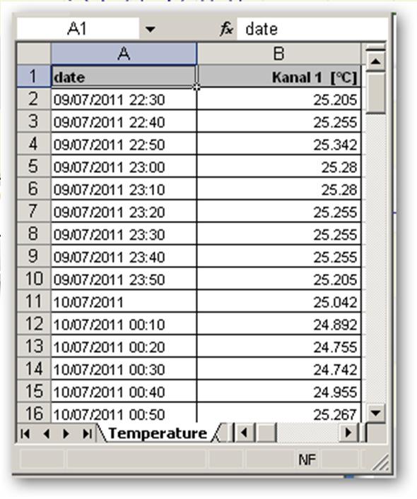
48 4.9.3 Printing For a printout, the paper size, the orientation, and the printer must first be selected. Then, click on Print to change to the print preview. Click on Print to start the printing process Microsoft Excel Export A series of data can be exported into an Excel table. Click on Excel for this

49
Quick Start Guide. Data Logger TrueLog100
 Quick Start Guide Data Logger TrueLog100 Antenna Port 3 Port 4 1 1 1 1 Port 1 1 Port 2 RSSI PC Measure SIM + Battery + Solar Power Supply Figure 1: Top view of the data logger TrueLog100. All ports and
SCHMIDT Programming Tool SS 20.4xx Instructions for Use
 SCHMIDT Programming Tool SS 20.4xx Instructions for Use SCHMIDT Programming Tool SS 20.4xx Table of Contents 1 Important Information... 3 2 Field of Application... 4 3 Scope of Delivery... 4 4 Programming
GSM HOME SECURITY SYSTEM
 Cell /Mobile phone home security system GSM HOME SECURITY SYSTEM Model : BS120 TABLE OF CONTENTS 1. FEATURES... 1 2. APPLICATION... 2 3. SPECIFICATIONS... 3 4. FRONT PANEL & LAYOUT DESCRIPTION...6 5. BASIC
TempLog & RH/TempLog User Guide. Sixth Edition First print Printed in July
 TempLog & RH/TempLog User Guide Sixth Edition First print Printed in July 2003 www.4oakton.com Contents Using the Guide... 15 Chapter 1 OaktonLog... 17 1.1. Overview... 18 1.2. Getting Started... 19 1.3.
MultiLog LX logger. MultiLog LX USER MANUAL
 Page 1 MultiLog LX USER MANUAL 34, route de Saint Romain - 69450 St Cyr au Mont Or - France Tél. +33 (0)4 72 53 11 53 - Fax +33 (0)4 78 83 44 37 - e-mail : hydreka@hydreka.fr Version Janvierr 2009 Page
LabEXCEL Clino. Manual. WYLER AG Im Hölderli CH-8405 WINTERTHUR Switzerland. Tel (0) Fax (0)
 Fax (0)") WYLER AG Im Hölderli CH-8405 WINTERTHUR Switzerland Tel. 0041 (0) 52 233 66 66 Fax. 0041 (0) 52 233 20 53 Homepage: http://www.wylerag.com E-Mail: wyler@wylerag.com Manual LabEXCEL Clino "LabEXCEL Clino"
WYLER AG Im Hölderli CH-8405 WINTERTHUR Switzerland Tel. 0041 (0) 52 233 66 66 Fax. 0041 (0) 52 233 20 53 Homepage: http://www.wylerag.com E-Mail: wyler@wylerag.com Manual LabEXCEL Clino "LabEXCEL Clino"
GPRS Pager 3 INSTALATION AND USER MANUAL
 GPRS Pager 3 INSTALATION AND USER MANUAL 1 Table of contents 1 Main functions of the GPRS Pager3...3 2 Operating mode, installation...3 2.1 Installation if no local network is available...3 2.2 Instalation
1 Introduction Required components Datalogger TrueLog Baseboard... 1
 - 1 Contents 1 Introduction... 1 2 Required components... 1 2.1 Datalogger TrueLog100... 1 2.1.1 Baseboard... 1 2.1.2 Battery holder with 2 pole power plug... 1 2.2 USB cable for logger configuration...
Track-It User s Guide. 1. Table of Contents. Track-It User Guide
 Track-It User s Guide Track-It is a PC based (Windows XP / Vista/ Windows 7) program to enable a user to program and view data from the Track-It series of micro data loggers. The program allows the loggers
ModemUSB/E12 User Manual v0.1
 User Manual v0.1 TABLE OF CONTENTS TABLE OF CONTENTS...2 1. ATTENTION...3 2. FOR YOUR SAFETY...3 3. USER S SERVICE...5 4. BASIC INFORMATION...6 4.1 Introduction...6 4.2 Legal Notice...6 4.3 Contacts...6
GPRS-T1. Monitoring Converter. SATEL sp. z o.o. ul. Schuberta Gdańsk POLAND tel
 Monitoring Converter GPRS-T1 Program version 1.01 gprs-t1_en 04/09 SATEL sp. z o.o. ul. Schuberta 79 80-172 Gdańsk POLAND tel. + 48 58 320 94 00 info@satel.pl www.satel.pl WARNINGS The module should only
Quick Start Guide. The Automotive Internet Experience
 Quick Start Guide The Automotive Internet Experience Table of Contents System Requirements Package Contents Overview Wi2U router Vehicle Installation Start-up Display Settings Regulatory Information Technical
CAMit I Camera with built in Modem
 CAMit I Camera with built in Modem User s Manual CAMit I AP revision: 3.3 CAMit I Setup revision: 2.0.1 Manual revision: 2.0 Date: February 27, 2002 Congratulations You just acquired a fine product from
TELTONIKA ModemUSB/G10 User Manual v0.1
 Address: Žirmūnų g. 27, Vilnius LT-09105, Tel.: +370 5 2127472, Fax: +3705 276 1380, E-mail: info@teltonika.lt TELTONIKA User Manual v0.1 TABLE OF CONTENTS TABLE OF CONTENTS... 2 1. ATTENTION... 3 2. FOR
TROVIS-VIEW 4 Software TROVIS Operating Instructions EB 6661 EN. Electronics from SAMSON
 TROVIS-VIEW 4 Software TROVIS 6661 Operating Instructions Electronics from SAMSON EB 6661 EN Edition January 2015 Definition of signal words DANGER! Hazardous situations which, if not avoided, will result
testo easyheat Configuration and Analysis software Instruction manual
 testo easyheat Configuration and Analysis software Instruction manual en 2 General Information General Information This documentation includes important information about the features and application of
MobilSwitch-5c. 1. Operation of the GSM device: Multi channel GSM signaling and remote control unit with analog, digital, counter inputs
 MobilSwitch-5c Multi channel GSM signaling and remote control unit with analog, digital, counter inputs The MobilSwitch-5c GSM device is developed for industrial signaling and remote controlling purposes.
Dual channel temperature logger with two voltage inputs 0-5V Instruction Manual
 LOGGER S0541 Dual channel temperature logger with two voltage inputs 0-5V Instruction Manual Instruction Manual for use of S0541 logger Instrument is designed for measurement and record of temperature
GSM communicator G16 USER MANUAL
 USER MANUAL UAB TRIKDIS Draugystės str. 17, LT-51229 Kaunas LITHUANIA E-mail: info@trikdis.lt Webpage: www.trikdis.lt Contents SAFETY REQUIREMENTS... 2 DESCRIPTION... 3 LIST OF COMPATIBLE CONTROL PANELS...
MobilGate - 128d. 1. Operation of MobilGate-128d. Gate and barrier control GSM module with 2 inputs and 2 outputs for 128 phone numbers
 MobilGate - 128d Gate and barrier control GSM module with 2 inputs and 2 outputs for 128 phone numbers MobilGate-128d is an industrial GSM module developed for remotely controlling doors, garage doors
GPRS-T4. GPRS/SMS Reporting Module. SATEL sp. z o.o. ul. Schuberta Gdańsk POLAND tel
 GPRS/SMS Reporting Module GPRS-T4 Program version 3.01 gprs-t4_en 10/13 SATEL sp. z o.o. ul. Schuberta 79 80-172 Gdańsk POLAND tel. + 48 58 320 94 00 info@satel.pl www.satel.eu WARNINGS The module should
User Manual. HOPPECKE sun powerpack premium. service software
 User Manual HOPPECKE sun powerpack premium service software Contents 1. INTRODUCTION 4 2. TARGET GROUP 4 3. MEANS OF REPRESENTATION 4 4. BASIC INFORMATION FOR APPLICATION USE 5 4.1. System requirements
HD32MTLogger Software Manual for the instrument HD32MT.1 Introduction
 HD32MTLogger Software Manual for the instrument HD32MT.1 Introduction WARNING: The software must always be run as administrator! The HD32MTLogger program allows management of the HD32MT.1 datalogger from
User Manual Revision 1.02
 User Manual Revision 1.02 Manufactured by Contents 1. Introduction... 4 2. Disclaimer and Warranty... 4 3. Specifications... 5 4. Features... 5 5. Quick Start Guide... 6 5.1 Hardware... 6 5.2 Software...
APS-3 Revision Important Quick Start Guide. Typical Box Contents
 APS-3 Revision 3.0.0 Important Quick Start Guide Congratulations on purchasing your new APS-3 System. This Important Quick Start Guide contains information you need to set up and begin using your APS-3.
MobilTherm 2ad. 1. How the interface works: GSM temperature alarm module with auxiliay inputs and relay outputs
 MobilTherm 2ad GSM temperature alarm module with auxiliay inputs and relay outputs The MobilTherm-2ad is a GSM temperature and remote signaling module, designed for GSM based remote control, remote signal.
Owners Manual i-bdl Battery Data Logger
 Owners Manual i-bdl Battery Data Logger Ref : PM-AR-BDL Date Part No : BDL01 (Battery Data Logger 01) Features Suitable for batteries up to 24 V Extremely low operating current Adjustable measuring intervals
User's Guide. For CarChip and CarChip E/X 8210 & 8220
 User's Guide TM For CarChip and CarChip E/X 8210 & 8220 Product Number: 8210, 8220 Davis Instruments Part Number: 7395.064 DriveRight CarChip User s Manual Rev A (January 2, 2003) Davis Instruments Corp.,
POWER VISION INSTRUCTION MANUAL
 NETWORK ANALYSIS SOFTWARE POWER VISION INSTRUCTION MANUAL (M98135801-03-11B) CIRCUTOR S.A. INDEX 1.- POWER VISION SOFTWARE INSTALLATION... 4 2.- INTRODUCTION TO POWER VISION... 12 3.- COMMUNICATIONS...
FLOWgate500. Software Manual. Software Manual FLOWgate500 Release 2.2. Revision number: V2.2. Manufacturer: SICK AG. Erwin-Sick-Str.
 FLOWgate500 Software Manual Software Manual FLOWgate500 Release 2.2 Revision number: V2.2 Manufacturer: SICK AG Erwin-Sick-Str.1 D-79183 Waldkirch Germany Place of manufacture: SICK Engineering GmbH Bergener
M170 USER'S / INSTALLER'S MANUAL V1.1 REV. 11/2016
 M170 USER'S / INSTALLER'S MANUAL V1.1 REV. 11/2016 00. CONTT INDEX 01. SAFETY INSTRUCTIONS STANDARDS TO FOLLOW 02. THE DEVICE DEVICE FUNCTIONS TECHNICAL CHARACTERISTICS VISUAL APPEARANCE 03. INSTALLATION
Instruction manual. testo easyemission Software
 Instruction manual testo easyemission Software en 2 General Information General Information This documentation includes important information about the features and application of the product. Please read
Operating manual. GTL - Configuration tool. Please keep the manual for future use.
 Operating manual GTL - Configuration tool Please keep the manual for future use. V1.00-01 GREISINGER Electronic GmbH Hans-Sachs-Str. 26 93128 Regenstauf Germany Fon +49(0)9402-9383-0 Fax +49(0)9402-9383-33
CORD-XL Dual-Channel Electronic Chart Recorder User s Manual
 CORD-XL Dual-Channel Electronic Chart Recorder User s Manual Rohrback Cosasco Systems Inc. 11841 E. Smith Ave Santa Fe Springs, CA 90670 Tel: (562) 949-0123 Fax: (562) 949-3065 P/N 720701-Manual Rev E
FIFOTRACK MOTORCYCLE/VEHICLE GPS TRACKER
 FIFOTRACK MOTORCYCLE/VEHICLE GPS TRACKER Model: S20 Version: V1.1 www.fifotrack.com Copyright and Disclaimer All copyrights belong to Shenzhen fifotrack Solution Co., Ltd. You are not allowed to revise,
Altus APS3G Quick Start guide
 Altus APS3G Quick Start guide Revision 1.0.1 Congratulations on purchasing your new Altus APS3G System. This Important Quick Start Guide contains information you need to set up and begin using your Altus
GPRS/SMS Reporting Module GPRS-T2
 GPRS/SMS Reporting Module GPRS-T2 Program version 2.01 gprs-t2_en 11/11 SATEL sp. z o.o. ul. Schuberta 79 80-172 Gdańsk POLAND tel. + 48 58 320 94 00 info@satel.pl www.satel.eu WARNINGS The module should
OPERATING MANUAL GSM-2
 OPERATING MANUAL GSM-2 GSM-2 Operating Manual 05-2010 Page 1/51 Content 1.1 GSM-2 Overview... 4 1.2 GSM-2 Features and Advantages... 4 2 General Description / GSM-2 Communication... 5 2.1 GSM Datamanager...
mobile PhoneTools User s Guide
 mobile PhoneTools User s Guide Contents Requirements...2 Installing mobile PhoneTools...3 Mobile installation and configuration...4 Online registration... 6 Uninstalling mobile PhoneTools... 6 mobile PhoneTools
USB Temperature and Humidity Data Logger Instruction Manual
 USB Temperature and Humidity Data Logger Instruction Manual 1 4 2 3 5 1. Display 2. Set key 3. + key 4. - key 5. USB port - 1 - 1. Temperature 4 2. MAX/MIN value 5 3. Humidity 1 2 3 4. Memory status 6
First Edition Termologger USB & OSAKA MicroLab Lite User guide
 First Edition Termologger USB & OSAKA MicroLab Lite User guide First Print February 2007 Introduction The Termologger USB is a compact 16-bit USB data logger designed for accurate temperature monitoring
FX Tools Software Package - FX CommPro N2 User s Guide
 User s Guide FX CommPro N2 Issue Date September 25, 2008 FX Tools Software Package - FX CommPro N2 User s Guide FX Tools Software Package FX CommPro N2... 3 Introduction...3 Installation... 4 Installing
MicroLite & MicroLab Lite User Guide. First Edition First Print February 2007 Fourier Systems Ltd.
 MicroLite & MicroLab Lite User Guide First Edition First Print February 2007 Fourier Systems Ltd. Contents Introduction... 1 Chapter 1 Using the MicroLite... 2 1.1. Overview... 3 1.2. Getting Started...
GSM Unit PU from software version Connecting cable RJ 12/ RJ 12, enclosed
 Document number A 30594 00 IT 74 1 CMC-TC GSM Unit DK 7320.820 Important note: For reasons of clarity, these user instructions contain only the most significant details and information and similarly cannot
Noise Guide. Manual UK.
 Noise Guide Manual UK www.soundear.com TABLE OF CONTENTS CONGRATULATIONS ON YOUR NEW NOISE GUIDE 3 BEFORE YOU START 4 Box Contents 4 Installing the device 4 How to insert the USB memory 5 How does Noise
EU Driver s Hours Rules covered by Digifobpro. Table of contents
 EU Driver s Hours Rules covered by Digifobpro Digifobpro provides analysis of Driver Cards both in it s Quick View and Driver Card - Download features ( see Digifobpro Functions page 4). There follows
HDT-318 Thermo-Hygrometer with Data Logger. (Air Humidity/Temperature) Instruction Manual
 Instruction Manual") HDT-318 Thermo-Hygrometer with Data Logger (Air Humidity/Temperature) Instruction Manual CONTENTS 1. SAFETY INFORMATION... 2 2. GENERAL DESCRIPTION... 2 3. FEATURES... 2 4. SPECIFICATIONS... 3 5. SYMBOL
HDT-318 Thermo-Hygrometer with Data Logger (Air Humidity/Temperature) Instruction Manual CONTENTS 1. SAFETY INFORMATION... 2 2. GENERAL DESCRIPTION... 2 3. FEATURES... 2 4. SPECIFICATIONS... 3 5. SYMBOL
TELTONIKA ModemCOM/G10 (CM1100) User Manual V0.1
 User Manual V0.1") TELTONIKA ModemCOM/G10 (CM1100) User Manual V0.1 Table of Contents TABLE OF CONTENTS...2 1. ATTENTION...3 2. SAFETY INSTRUCTION...3 3. LEGAL NOTICE...5 4. INTRODUCTION...5 5. PACKAGE CONTENTS...5 6. TECHNICAL
TELTONIKA ModemCOM/G10 (CM1100) User Manual V0.1 Table of Contents TABLE OF CONTENTS...2 1. ATTENTION...3 2. SAFETY INSTRUCTION...3 3. LEGAL NOTICE...5 4. INTRODUCTION...5 5. PACKAGE CONTENTS...5 6. TECHNICAL
SMS Transceiver V3 User manual
 SMS Transceiver V3 User manual SMS Transceiver V3 - User manual ver. 1.8.3 - Fw: 3.0.7 - Sw: 1.6.2 Contents Page 1. Introduction 3 2. Connections 3 2.1 Inputs 3 2.2 Outputs 3 2.3 Power supply 3 2.4 Contacts
AVL Tracking System TR-600
 AVL Tracking System TR-600 V 1.3 GlobalSat WorldCom Corporation 16F., No. 186, Jian 1 st Rd, Zhonghe Dist., New Taipei City 23553, Taiwan Tel: 886.2.8226.3799/ Fax: 886.2.8226.3899 service@globalsat.com.tw
FIFOTRACK VEHICLE GPS TRACKER. Model: S30 Version: V1.1
 FIFOTRACK VEHICLE GPS TRACKER Model: S30 Version: V1.1 www.fifotrack.com Copyright and Disclaimer All copyrights belong to Shenzhen fifotrack Solution Co., Ltd. You are not allowed to revise, copy or spread
M A C 3 Wind Speed Alarm & Controller
 M A C 3 Wind Speed Alarm & Controller Installation Instructions Thank you for purchasing the MAC3 wind speed alarm and controller. This manual is designed to lead you through a step-by-step process to
StarFinder Aire User Manual
 Document No.: Document Type: Security Level: 270-UM-001 User Manual Open StarFinder Aire User Manual (Preliminary) Version 1.00 Dec. 05, 2015 Copyright Laipac Technology Inc. Release History Revision Date
Quick Start Guide Vodafone Mobile Broadband USB Modem Stick Lite
 Quick Start Guide Vodafone Mobile Broadband USB Modem Stick Lite Welcome to the world of mobile communications 1 Welcome 2 Set up your USB Stick 3 Start the software 4 Software overview 5 Connect 6 SMS
MindSphere. Fleet Manager. Introduction to "Fleet Manager" 1. User interface for "Fleet Manager" 2. User rights in "Fleet Manager" 3.
 Introduction to "Fleet Manager" 1 User interface for "Fleet Manager" 2 MindSphere User rights in "Fleet Manager" 3 Asset navigation 4 Using extensions 5 System Manual V1801.K0507 V1801.K0214 Legal information
Mobil Switch-Nano. 1. Operation: Industrial grade GSM signalling and remote control module with common input and relay output
 Mobil Switch-Nano Industrial grade GSM signalling and remote control module with common input and relay output The MobilSwitch-Nano module is a general, industrial-grade GSM module, developed for remote
Temperature logger with internal sensor Instruction manual
 LOGGER R0110 Temperature logger with internal sensor Instruction manual Manual for use of temperature logger R0110 Logger is designed for measurement and record of temperature from built-in internal temperature
OPT2011. High-performance distance sensor. Operating Instructions
 OPT2011 High-performance distance sensor Operating Instructions Status: 15/07/2013 2 Table of Contents 1. Use for Intended Purpose 4 2. Safety Precautions 4 2.1. Safety Precautions 4 2.2. Laser/LED warning
User Manual. 1. Introduction MtrackScout OBD-II Compliant... 2
 User Manual Contents 1. Introduction... 2 1.1. MtrackScout OBD-II Compliant... 2 2. Hardware Features... 2 2.1. OBD-II Protocol... 2 2.2. Micro USB Connection... 2 2.3. Buzzer... 2 2.4. Power Supply...
Operation Manual GSM modem irz TG42-232
 Operation Manual GSM modem irz TG42-232 Table of Contents 1. Introduction... 4 1.1. About this Document... 4 1.2. Service Information... 4 1.3. Safety Precautions... 4 2. Overview... 5 2.1. Purpose...
1. Introduction to the Remotefox system
 1 Table of contents 1. Introduction to the Remotefox system... 3 2. Scope of delivery of the complete system... 5 3. Preparing the Remotefox hardware... 5 4. Configuring the SIM card... 7 5. The Remotefox
(For IT-550) CODE : I
 CODE : I") (For IT-550) CODE : I1000153000 INSTRUCTION MANUAL Before using the INFRARED THERMOMETER, throughly read this manual for the proper operation. After reading, keep this manual for future reference. Unauthorized
(For IT-550) CODE : I1000153000 INSTRUCTION MANUAL Before using the INFRARED THERMOMETER, throughly read this manual for the proper operation. After reading, keep this manual for future reference. Unauthorized
THE WORLD OF WEATHER DATA
 THIES Clima Meteorology and Environmental measurements. Datalogger DL16 PRO 2009 Adolf Thies GmbH & Co. KG 1 Content 1. Highlights 2. Introduction 3. Connectivity 4. Configuration 5. Miscellaneous Configuration
TFA. KlimaLogg Pro. User Manual. Revision: 1.1
 TFA KlimaLogg Pro User Manual Revision: 1.1 Table of Contents Overview... 2 Getting Started... 2 Setting up the KlimaLogg Pro device... 2 Installing the USB-Stick... 2 Installation... 2 System Requirements...
UP100-GSM. GSM based intercom and access control. Installation and user manual
 UP100-GSM GSM based intercom and access control Installation and user manual UP100-GSM REV.1.4 20/01/2014 Table of contents 1 Functions...3 2 Features...3 3 Application area...3 4 Operation...3 4.1 Visitor
-Table of Contents- 1. Overview Installation and removal Operation Main menu Trend graph... 13
 Thank you for buying Data Analysis Software. In order to use this software correctly and safely and to prevent trouble, please read this manual carefully. Notice 1. No part of this manual can be reproduced
TROVIS-VIEW 4 Software TROVIS Operating Instructions EB 6661 EN. Electronics from SAMSON
 TROVIS-VIEW 4 Software TROVIS 6661 Operating Instructions Electronics from SAMSON EB 6661 EN Edition August 2017 Definition of signal words DANGER! Hazardous situations which, if not avoided, will result
ETM350C & ETM450C User Manual
 Industrial Ethernet Router ETM350C & ETM450C User Manual Features ETM350C // ETM450C: HSDPA/UMTS 850/900/2100MHz // 850/900/1900/2100MHz GSM/GPRS 900/1800MHz // 850/900/1800/1900MHz HSUPA 14.4Mbps DL,
GREISINGER electronic GmbH. D Regenstauf, Hans-Sachs-Straße 26. T-Logg 120 W -... T-Logg 120 K -...
 E39.0.1X.6C-01 Data logger for standard signals as of version 1.0 Operating Instruction T-Logg 120... T-Logg 120 W -... T-Logg 120 K -... GREISINGER electronic GmbH D - 93128 Regenstauf, Hans-Sachs-Straße
Cellcop Communicator CP72u-M
 Cellcop Communicator CP72u-M Feb 2015 User Manual ABOUT THE CELLCOP COMMUNICATOR SYSTEM The Cellcop GSM communicator system is based on SMS and GPRS technology. It uses standard cellphone technology for
Hand-held thermometer Model CTH6200
 Calibration technology Hand-held thermometer Model CTH6200 WIKA data sheet CT 51.01 for further approvals see page 3 Applications Calibration service companies and service industry Measurement and control
VISY-X. Technical Documentation. Cinterion MC 55 i. Edition: Version: 1 Article no.:
 Technical Documentation VISY-X Edition: 2016-10 Version: 1 Article no.: 350033 FAFNIR GmbH Schnackenburgallee 149 c 22525 Hamburg Tel.: +49 / 40 / 39 82 07 0 Fax: +49 / 40 / 39 06 339 Table of contents
Technical Advisory Bulletin
 Date: Monday, December 13, 2010 Number: TAB-09-010 To: US Distributors Notice: GS3055-I & GS3060 Flash Update Utility This is to advise you that DSC has released the GS3055-I and GS3060 Flash Update Utility
GSM manual and Software User Guide
 GSM manual and Software User Guide ENGLISH TD 211-1-ENG www.euromag.com 2 EUROMAG GSM Manual and Software User Guide INDEX 1. SOFTWARE USER GUIDE 4 2. SIM INSERT / REPLACEMENT PROCEDURE 18 3. GSM MESSAGES
EPS 06 in rear housing type A1
 Field Installation and / or Replacement of RACO Electronic Position Sensor Board EPS 02 & EPS 06 - Electronic Limit Switches - Analog Output Position Signal - Very Accurate - Easy To Use - Robust - Dependable
GSM communicator GD-06 Allegro Complete manual
 GSM communicator GD-06 Allegro Complete manual The GD-06 ALLEGRO is a universal GSM dialer and controller. It can be used for both home and industrial automation purposes, for security applications or
Graphical User Interface V1.0.3
 Graphical User Interface V1.0.3 Application User Guide 2015 MCI Solutions. All rights reserved. 240815-01 www.mcisolutions.ca Page ii Getting Started Table Of Contents Introduction.................................................
Instruction Upgrade of firmware
 WYLER AG Im Hölderli CH-8405 WINTERTHUR Switzerland Tel. 0041 (0) 52 233 66 66 Fax. 0041 (0) 52 233 20 53 Homepage: http://www.wylerag.com E-Mail: wyler@wylerag.com Instruction Upgrade of firmware Mai
Instructions for I40XT GameSpy Digital Camera
 Instructions for I40XT GameSpy Digital Camera THANK YOU for your purchase of the Model. Please read this booklet before using the unit. If you should have any questions about this product or any other
Power Vision 1.7 (Cod )
") ELECTRICAL NETWORK ANALYSIS SOFTWARE Power Vision 1.7 (Cod. 775 353) USER S MANUAL (Cod. M 981 358 / 05B) 2005 - CIRCUTOR, S.A. INDEX 1.- POWER VISION SOFTWARE INSTALLATION...4 2.- INTRODUCTION TO POWER
ELECTRICAL NETWORK ANALYSIS SOFTWARE Power Vision 1.7 (Cod. 775 353) USER S MANUAL (Cod. M 981 358 / 05B) 2005 - CIRCUTOR, S.A. INDEX 1.- POWER VISION SOFTWARE INSTALLATION...4 2.- INTRODUCTION TO POWER
Drop-Off Release Transmitter
 Project: Drop-Off Release Transmitter Title: User's Manual Document No.: Drop-off User s Manual Version: 1.3 Last Change: 31.03.2011 Name Date Signature Prepared by Annette Krop- Benesch 23.12.2010 Edited
Dupline. Data Logger. Types G , G Product Description. Ordering Key G Type Selection. Input/Output Specifications
 Dupline Data Logger Types G 800 006, G 800 106 Product Description Programmable channel generator with optional built-in GSM Modem Event and time based data logging functions for digital, analog and counter
A1000 GSM ALARM DEVICE
 A1000 GSM ALARM DEVICE USER MANUAL A1000-REV2.1-1604 FW-A1000v2.93 ERBAŞ TEKNOLOJİ Innovative Solutions 1 www.erbasteknoloji.com SAFETY INSTRUCTIONS - This user manual contains important notices for installation,
Technical data. General specifications. factory setting: 125 ms Memory Non-volatile memory Write cycles Indicators/operating means
 Model Number Single head system Features IO-link interface for service and process data Programmable via DTM with PACTWARE Switch output and analog output Selectable sound lobe width Synchronization options
SMARTLINE WIRELESS INTERFACE SYSTEM INSTALLATION MANUAL
 SMARTLINE WIRELESS INTERFACE SYSTEM INSTALLATION MANUAL SmartLine (Wireless) Installation Manual v1.9 1.Contents 2. Overview...2 Equipment List...2 Introduction... 2 Monitoring Software Compatibility...2
On-board wireless temperature and humidity logger
 On-board wireless temperature and humidity logger v6.3 BT 1 Contents 1. Introduction... 4 2. Description of the operation... 4 3. Technical data... 6 4. Loggicar R package contents... 7 5. Logger overview...
GSM-X. Communication module. Quick installation guide. Full manual is available on Firmware version 1.02 gsm-x_sii_en 08/18
 GSM-X Communication module Quick installation guide Full manual is available on www.satel.eu Firmware version 1.02 gsm-x_sii_en 08/18 SATEL sp. z o.o. ul. Budowlanych 66 80-298 Gdańsk Poland tel. +48 58
IP68. Autarkic Data Loggers - MT-051 / MT-713 / MT-723
 Autarkic Data Loggers - MT-051 / MT-713 / MT-723 Use in the most demanding environments These data loggers are designed for use in difficult to reach and widely distributed locations. In places where neither
DPM-3221 Digital DC Power Meter with data logging capability.
 Introduction DPM-3221 Digital DC Power Meter with data logging capability. User Manual As a digital DC power meter, it measures the real time DC Voltage (5-60V), DC Current (0-200 A with the correct shunt),
User manual GeoChaser Control
 User manual GeoChaser Control 1.Introduction The GeoControle is a GPS tracking system designed for vehicle tracking. The device has superior reception sensitivity, fast positioning and supports four-band
motcom loganalyser User Manual
 User Manual Part No. 2 900 04 10000 Release 07.03.2016 English revision 160825 Kurt-Schumacher-Str. 28-30 66130 Saarbrücken, Germany e-mail: info@motcomgmbh.com web: www.motcomgmbh.com Contents Introduction...
RMS Monitoring Software System Operation
 RMS Monitoring Software System Operation 2017 ROTRONIC AG Bassersdorf Switzerland 2017 ROTRONIC AG Bassersdorf Switzerland Page 2 of 27 Contents Contents... 3 1 Overview... 4 1.1 System Requirements...
INSTRUCTION MANUAL. IBREXDLL Software for MS Excel. M e t r o l o g y. Messtechnik GmbH & Co. KG
 M e t r o l o g y INSTRUCTION MANUAL Software for MS Excel Document No. : D2MF710 001 Edition : April 2009 Copyright : IBR Messtechnik GmbH & Co. KG Contents 1. Introduction... : 3 2. Features... : 3 3.
X-Log Expert Data Logger
 > data loggers X-Log Expert Data Logger Highlights Built-in internet stack with web server Setup and data display by any web browser Data-Push to up to three different FTP sites Internal FTP site for easy
irz MC55iT GPRS class 10 GSM modem USER MANUAL
 irz MC55iT GPRS class 10 GSM modem USER MANUAL Contents 1. Safety Requirements... 3 2. General Information...4 2.1. Purpose of the Device...4 3.1. Configuration...4 3.2. Parameters...4 3.3. Exterior Appearance...6
PIVOT CMS CLIENT SOFTWARE USER MANUAL
 PIVOT CMS CLIENT SOFTWARE USER MANUAL 1 CMS USER GUIDE 1.1 PC REQUIREMENT Recommended PC Requirement OS CPU VGA RAM HDD Graphics Card OS CPU VGA RAM HDD Windows Vista, 7 or higher Intel Core2Quad Q9400
GS828. GPRS Data Logger
 Sirius Corp GPRS Data Logger Multi Channels Data Logging & Wireless Transmission Upload Data via GPRS and SMS on schedule or alarm triggered Programmable data logging and upload interval Support sensors
SOFREL LT/LT-US Data loggers Wastewater network solutions
 SOFREL LT/LT-US Data loggers Wastewater network solutions SOFREL LT and LT-US data loggers are designed to monitor wastewater and rainwater networks (collectors, Combined Sewer Overflows, etc.). Robust,
ADS PrimeWorks User Manual
 ADS PrimeWorks User Manual November 2010 QR 775018 A0 ADS LLC 4940 Research Drive Huntsville, AL 35805 Telephone (256) 430-3366 / Fax (256) 430-6633 www.adsenv.com Copyright 2010 ADS LLC. All rights reserved.
Data Logger November 2017
 Data Logger November 2017 Summary 1- INTRODUCTION... 3 2- INSTALLATION... 4 3- DATA LOGGER SETTING... 5 3-1. Loggers setting... 5 3-1-1. By tasks... 7 3-1-2. By logger data sending s... 7 3-2. Probes setting...