Intel Optane DC Persistent Memory Module (DCPMM) - DSM
|
|
|
- Melvyn Morris
- 5 years ago
- Views:
Transcription

1 Intel Optane DC Persistent Memory Module (DCPMM) - DSM Interface Revision V1.8 October, 2018 The following changes make up the publically released DSM V1.8 specification available on - Get SMART Health Info: o Renamed Spare Blocks Remaining field and Validity bit to Percentage Remaining o Added Health Reason field and new validity bit o Percentage Used has been deprecated and renamed Reserved o Added notes to DSC and LSS that these indicators are both controlled by the LSS latch enable logic o Add DCPMM Specific SMART Data using new Table 3-3 o Rename Vendor Specific Data to DCPMM Specific Data - Get SMART Threshold - Set SMART Threshold o Renamed Spare Blocks Remaining field to Percentage Remaining - NVDIMM Security Management o Addition of Master Passphrase support to match FIS 1.13 o Addition missing return status 01 - Failure - Function Not Supported returned for most security commands if not in correct state o Theory of Operation Updated Application In-band Get Security State Sequence diagram with Master Passphrase additions o Get Security State Updated both flows for Security Theory of Operation section. Note the updated GetSecurityState DSM status checking. These are clarifications only and not a logic change Add new return values to report Master Passphrase Enabled and Master Passphrase Limit Expired to match FIS 1.13 Added Extended Security State field to allow backwards compatibility with the V1.7 DSM spec o Set Master Passphrase New DSM to match FIS 1.13 addition of Master Passphrase feature o Secure Erase NVDIMM Updated responsibilities to better explain invalidating CPU caches Renamed Secure Erase NVDIMM w User Passphrase o Secure Erase NVDIMM w Master Passphrase New command to avoid changes to existing Secure Erase feature o Unlock Unit Added missing responsibility to invalidate CPU caches after an Unlock Unit has completed
2 Notices No license (express or implied, by estoppel or otherwise) to any intellectual property rights is granted by this document. Intel disclaims all express and implied warranties, including without limitation, the implied warranties of merchantability, fitness for a particular purpose, and non-infringement, as well as any warranty arising from course of performance, course of dealing, or usage in trade. This document contains information on products, services and/or processes in development. All information provided here is subject to change without notice. Contact your Intel representative to obtain the latest forecast, schedule, specifications and roadmaps. The products and services described may contain defects or errors known as errata which may cause deviations from published specifications. Current characterized errata are available on request. Copies of documents which have an order number and are referenced in this document may be obtained by calling or by visiting Intel and the Intel logo are trademarks of Intel Corporation in the U.S. and/or other countries. *Other names and brands may be claimed as the property of others Intel Corporation. 2
3 Contents Contents 1 Introduction... 5 Document Scope... 5 Related Documents... 5 Terminology _DSM Interface for NVDIMM ACPI0012 Root Device _DSM Interface for the NVDIMM Device... 7 SMART Health Monitoring & Alarms Get SMART and Health Info (Function Index 1) Get SMART Threshold (Function Index 2) Set SMART Threshold (Function Index 17) Command Effect Log Get Command Effect Log Info (Function Index 7) Get Command Effect Log (Function Index 8) Pass-Through Command (Function Index 9) Enable Latch System Shutdown (Function Index 10) Get Supported Modes (Function Index 11) NVDIMM FW Download Get FW Info (Function Index 12) Start FW Update (Function Index 13) Send FW Update Data (Function Index 14) Finish FW Update (Function Index 15) Query Finish FW Update (Function Index 16) Inject Error (Function Index 18) NVDIMM Security Management Theory Of Operation Get Security State (Function Index 19) Set Passphrase (Function Index 20) Disable Passphrase (Function Index 21) Unlock Unit (Function Index 22) Freeze Lock (Function Index 23)
4 3.8.7 Secure Erase NVDIMM w User Passphrase (Function Index 24) Overwrite NVDIMM (Function Index 25) Query Overwrite NVDIMM (Function Index 26) Set Master Passphrase (Function Index 27) Secure Erase NVDIMM w Master Passphrase (Function Index 28) Deprecated Functions Get Block NVDIMM Flags (Function Index 3) Get Namespace Label Size (Function Index 4) Get Namespace Label Data (Function Index 5) Set Namespace Label Data (Function Index 6)
5 1 Introduction Document Scope This document is targeted to writers of BIOS and OS drivers for NVDIMMs whose design adheres to the NFIT Tables in the ACPI V6.2 specification. This document specifically discusses the NVDIMM Device Specific Method (_DSM). Related Documents The related documents are: ACPI Specification Version 6.0, 6.1 & 6.2, 6.2 Errata A ( UEFI 2.7, 2.7 Errata A - NVDIMM Label Protocol, UEFI 2.7 NVDIMM BTT Layout ( This DSM Specification ( Terminology Refer to Table 1-1 for definitions of terms used in this document. Table 1-1 Terminology Term Intel Optane DC Persistent Memory Module or DCPMM or NVDIMM NFIT NVDIMM NVDIMM Namespace Label NVDIMM Namespace Persistent Memory SPA The non-volatile DDR DIMM form factor byte addressable PMEM. Also referred to throughout this specification as the NVDIMM or DCPMM. The NVDIMM Firmware Interface Table defines the ACPI 6.2 specified information created by the BIOS to inform the OS about NVDIMMs in the system. Non-volatile memory in a DIMM form factor. See DCPMM above. Labels, stored at a known location on NVDIMMs, which define the DIMM s contribution to NVDIMM Namespaces. This is a software mechanism; the DIMM itself just sees the labels as part of the overall data stored on the DIMM. See the ACPI 6.2 NVDIMM Label additions and the UEFI 2.7 NVDIMM Label Protocol additions to describe this in more detail. Similar to an NVMe Namespace or a Logical Unit (LUN) on a SCSI disk, this is a software mechanism for managing ranges of persistence on NVDIMMs. See the ACPI 6.2 NVDIMM Label additions, and the UEFI 2.7 NVDIMM Label Protocol additions to describe this in more detail. -addressable memory that retains its contents after power loss. System Physical Address. A physical address on the host operating system. 5
6 2 _DSM Interface for NVDIMM ACPI0012 Root Device All Root ACPI0012 scoped _DSMs and NVDIMM layout / Label interfaces are now found in the following specifications and have been removed from this document, which will now only document the Intel NVDIMM specific _DSMs. Please see: ACPI Specification V6.0 Initial NVDIMM NFIT additions ACPI Specification V6.1 Addition of Common ARS _DSMs, Clear Uncorrectable Error _DSM ACPI Specification V6.2 Addition of NVDIMM Label API, ARS Error Injection _DSMs ACPI Specification V6.2 Errata A Addition of RAS Capabilities structure as a new NFIT structure UEFI Specification V2.7 See additions of NVDIMM Label Protocol and BTT Layout UEFI Specification V2.7 Errata A Small fixes to the Label Protocol that remove inconsistencies with existing implementations 6
7 3 _DSM Interface for the NVDIMM Device Platforms that have the _DSM interface implemented, as outlined in this section, can support a NVDIMM region with Region Format Interface Code (RFIC) of 0x0201 or 0x0301. Note that the _DSM methods defined in this section are required to be implemented under NVDIMM devices that are child devices of the NVDIMM Root Device associated with _HID of ACPI0012 in ACPI name space hierarchy. The following tables outlines the required Arg1, Arg2 parameters that are to be utilized for this version of the specification. The platform shall support the Arg1 - Revision Id = 1 and Arg1 - Revision Id = 2 Function Indexes simultaneously as outlined below. No other Arg1 - Revision Id values are supported at this time. Arg0 UUID AC30-0D11-11E C9A66 Table 3-A Supported Function Index for Arg1 - Revision Id = 1 Arg1 - Revision Id Arg2 Function Index _DSM Function Name 1 0 Query implemented commands per ACPI Specification (returns the list below based on Arg1 - Revision Id = 1). 1 Get SMART and Health Info 2 Get SMART Threshold 3 Get Block NVDIMM Flags 4 Deprecated - Get Namespace Label Data Size 5 Deprecated - Get Namespace Label Data 6 Deprecated - Set Namespace Label Data 7 Get Command Effect Log Info 8 Get Command Effect Log 9 Pass-Through Command 10 Enable Latch System Shutdown 7
8 Table 3-B Supported Function Index for Arg1 - Revision Id = 2 Arg1 - Revision Id Arg2 Function Index _DSM Function Name 2 0 Query implemented commands per ACPI Specification (returns the list below based on Arg1 - Revision Id = 2). 1 Get SMART and Health Info 2 Get SMART Threshold 3 Deprecated - Get Block NVDIMM Flags 4 Deprecated - Get Namespace Label Data Size 5 Deprecated - Get Namespace Label Data 6 Deprecated - Set Namespace Label Data 7 Get Command Effect Log Info 8 Get Command Effect Log 9 Pass-Through Command 10 Enable Latch System Shutdown 11 Get Supported Modes 12 Get FW Info 13 Start FW Update 14 Send FW Update Data 15 Finish FW Update 16 Query Finish FW Update 17 Set SMART Threshold 18 Inject Error 19 Get Security State 20 Set Passphrase 21 Disable Passphrase 22 Unlock Unit 23 Freeze Lock 24 Secure Erase NVDIMM w User Passphrase 25 Overwrite NVDIMM 26 Query Overwrite NVDIMM 27 Set Master Passphrase 28 Secure Erase NVDIMM w Master Passphrase 8
9 Arg3 A package containing parameters for the function specified by the UUID, Revision ID, and Function Index. The layout of the package for each command along with the corresponding output are illustrated in the respective Function Index description sections. For DSM functions that take an input argument, Arg3 is a package containing a Buffer, list of bytes, values. For DSM functions that do not take an input parameter, Arg3 is an empty package. The output of all functions in the DSM is a Buffer with a list of bytes. The first four bytes provide and Extended for the DSM function. Depending on the status code, additional bytes may follow the status bytes. If status bytes signal an error condition, the additional bytes are not present, unless some additional information is explicitly defined for the particular error code. If status bytes signal success, all output bytes defined for the function are present. The following table outlines the returned field common to all of the DSMs defined in this specification. The status adopts the following conventions for the _DSM function return status codes. This status can always be utilized for the status of each _DSM function, whether the specific status value is defined in the output buffer or not. Table 3-C Supported _DSM Return Values Return Value - s[1-0] Return Value - 0 Success 1 Failure - Function Not Supported 2 Failure - Non-Existing Memory Device 3 Failure - Invalid Input Parameters 4 Failure HW Error 5 Failure Retry Suggested - Command Timed Out, Other Command In Progress, Mailbox not Ready Typically an operation is executing and cannot be interrupted. Operations most likely to be executing are: ARS, Overwrite NVDIMM, and Finish FW Update. Software shall wait for those operations to complete utilizing Get ARS, Query Overwrite NVDIMM, or Query Finish FW Update before restarting an ARS, Overwrite NVDIMM, or FW Update sequence respectively. 6 Failure Unknown Reason 7 Function Specific Error (details in Extended ) 8 Failure Retry Suggested - Out of Resources 9 Failure HW Not Ready 10 Failure Invalid Security State 11 Failure Invalid Current Passphrase Supplied - Returned by the NVDIMM when the Current Passphrase does not match the saved passphrase. If the NVDIMM is also in the wrong security state, the Invalid Security State status is reported instead of this status. 9
10 SMART Health Monitoring & Alarms Get SMART and Health Info (Function Index 1) This command requests the device to return Smart and Health information for the requested device. Function Input None Function Output The following tables outline the expected output payload for this command. Table 3-1 Get SMART and Health Info Output Format 2 0 Defined above in Table 3-C Extended Smart and Health Data 2 2 Extended Output formatted as shown in Table 3-2. Table 3-2 SMART and Health Data Output Format Validity Flags 4 0 Validity Flags if the corresponding validation flag is not set in this field, it is indication to software that the corresponding field is not valid and must not be interpreted. Bit[0] if set to 1, indicates that Health field is valid Bit[1] if set to 1, indicates that Spare BlocksPercentage Remaining field is valid Bit[2] Reserved, shall return 0.if set to 1, indicates that Percentage Used field is valid Bit[3] if set to 1, indicates that Current NVDIMM Media Temperature field is valid Bit[4] if set to 1, indicates that Current NVDIMM Controller Temperature field is valid Bit[5] If set to 1, indicates that Latched Dirty Shutdown Count field is valid Bit[6] If set to 1, indicates that the AIT DRAM field is valid Bit[7] If set to 1, indicates that the Health Reason field is valid 10
11 Bit[8:7] Reserved, shall return 0. Bit[9] if set to 1, indicates that Alarm Trips field is valid Bit[10] if set to 1, indicates that Latched Last Shutdown field is valid Bit[11] if set to 1, indicates that Size of Vendor-specific SMART Data field is valid. If this field is not valid, the software will ignore the vendor-specific data fields. Bits[31:12] Reserved, shall return 0. Reserved 4 4 Shall return 0. Health 1 8 Health (HS): Overall health summary. Normal health is indicated by all HS bits being clear. Only one bit will be set at a time. Spare BlocksPercen tage Remaining Percentage UsedReserve d Bit[0] if set to 1, indicates Non-Critical condition, maintenance required but no data loss detected Bit[1] if set to 1, indicates Critical condition, features or performance degraded due to failures but no data loss detected Bit[2] if set to 1, indicates fatal condition, data loss is detected or is imminent. Bit[7:3] - Reserved, shall return Spare BlocksPercentage Remaining: Remaining modules life as a percentage value of factory expected life span. The value of 0 means that the warranted life span of the device has been reached. Spare Capacity as % of factory configured space. Valid range 0 to = All of the factory configured spare block capacity has been utilized 100 = None of the factory configured spare block capacity has been utilized 1 10 Reserved, shall return 0.Percentage Used: Device life span as percentage Valid range 0 to = the warranted life span of the device has been reached. Alarm Trips 1 11 Alarm Trips: Bits to signify if values have tripped their respective alarm thresholds Bit[0] - Spare BlocksPercentage Remaining Trip - If set then the Spare BlocksPercentage Remaining value has gone below the preprogrammed threshold limit Bit[1] NVDIMM Media Temperature Trip - If set then the NVDIMM Media temperature value has gone above the preprogrammed threshold limit Bit[2] NVDIMM Controller Temperature Trip - If set then the NVDIMM Controller temperature value has gone above the pre- 11
12 programmed threshold limit Current NVDIMM Media Temperature Current NVDIMM Controller Temperature Dirty Shutdown Count AIT DRAM Bits[7:3] - Reserved, shall return Current Media Temperature: Current temperature of the NVDIMM Media Bits[14:0] - Temperature in degree Celsius resolution. Bit[15] Sign bit for temperature (1 = negative, 0 = positive) 2 14 Current Controller Temperature: Current temperature of the NVDIMM Controller Bits[14:0] - Temperature in degree Celsius resolution. Bit[15] Sign bit for temperature (1 = negative, 0 = positive) 4 16 Latched Dirty Shutdown Count (LDSC) Number of times the NVDIMM Last Shutdown (LSS) was non-zero, indicating a dirty shutdown. Incremented anytime Last Shutdown (LSS)!= 0 & Latch System Shutdown is set by host SW (via Enable Latch System Shutdown _DSM). Count wraps back to 0 at overflow. Only updated and valid when Latch System Shutdown is enabled on the NVDIMM via Enable Latch System Shutdown AIT DRAM 00 AIT DRAM is disabled 01 AIT DRAM is enabled Health Reason If the AIT DRAM is disabled, it will cause a performance degradation and will trigger a SMART Health change to critical state 2 21 Health Reason: Provides additional reasons why the current Health is Non-Critical, Critical, or Fatal: Bit[0] 0% < Percentage Remaining <= 1% Bit[1] Package Sparing has occurred Bit[2] CAP Self-Test returns a Warning Bit[3] Percentage Remaining == 0 Bit[4] - Die Failure after Package Sparing (if available) Bit[5] AIT DRAM state is disabled Bit[6] CAP Self-Test Failed Bit[7] Critical internal state failure Bit[15:8] - Reserved Reserved Shall return 0. Last Shutdown 1 31 Latched Last Shutdown (LLSS): status of last shutdown 00 Clean shutdown All other Values Not Clean Shutdown, indicates that there was 12
13 Size of Vendor-s Specific SMART Data Vendor-s Specific SMART Data either a platform or memory device-related failure occurred when saving data targeted for this memory device. Dirty Shutdown Count (DSC) above maintains a count of the number of times a non-clean shutdown occurs. Only updated and valid when Latch System Shutdown is enabled on the NVDIMM via Enable Latch System Shutdown Size of Vendor-specific SMART Data in bytes. If set to 0, indicates that there is no vendor Vendor-sspecific SMART data Data that follows. Otherwise, indicates size of the Vendor-specific SMART data Data that follows Vendor-specific SMART Data. The contents of this byte array are vendor specific based on the hardware installed. See Table 3-3 DCPMM Specific SMART Data, below, for the Intel Optane DC Persistent Memory Module (DCPMM) specific field definitions The following table outlines the Intel DCPMM specific fields that are utilized with SMART Last Shutdown for both latched and unlatched usages. Please see the DCPMM specific FIS specification for details on the other vendor specific fields not outlined here. Note: These vendor specific fields apply to the Intel Optane DC Persistent Memory Module based products ONLY. Table 3-3 DCPMM Specific SMART Data Output Format Overall SMART payload DCPMM Specific SMART Reserved See FIS for specific values. May not read as 0. Unlatched Dirty Shutdown Count Latched Last Shutdown Details Unlatched Dirty Shutdown Count (UDSC) is the free running count of dirty shutdowns that have been detected by the NVDIMM. This count is not affected by the state of the LSS latch (controlled by the Latch System Shutdown command) Latched Last Shutdown Details shows the additional signals and state utilized by the NVDIMM when determining the final latched Last Shutdown and latched Dirty Shutdown Count. Multiple bits can be set. Bit[0] When set to 1, PM ADR Command Received Bit[1] When set to 1, PM S3 Received 13
14 Bit[2] - When set to 1, PM S5 Received Bit[3] - When set to 1, DDRT Power Fail Command Received Bit[4] - When set to 1, PMIC 12V/DDRT 1.2V Power Loss Occurred Bit[5] - When set to 1, PM Warm Reset Received Bit[6] - When set to 1, Thermal Shutdown Received Bit[7] - When set to 1, Controller FW State Flush Completed Reserved See FIS for specific values. May not read as 0. Latched Last Shutdown Extended Details Latched Last Shutdown Extended Details shows additional signals and state utilized by the NVDIMM when determining the final Latched Last Shutdown (LLSS) and Latched Dirty Shutdown Count (LDSC). Multiple bits can be set. Bit[0] - When set to 1, Viral Interrupt Received Bit[1] - When set to 1, Surprise Clock Stop Received Bit[2] - When set to 1, Write Data Flush Complete Bit[3] - When set to 1, PM S4 Received Bit[4] - When set to 1, PM Idle Received Bit[5] - When set to 1, DDRT Surprise Reset Received Reserved Reserved. Read as 0. Unlatched Last Shutdown Details Unlatched Last Shutdown Extended Details Unlatched Last Shutdown Details shows the additional signals and state utilized by the NVDIMM when determining the final Unlatched Dirty Shutdown Count. These details are not affected by the state of the LSS latch (controlled by the Latch System Shutdown command) Unlatched Last Shutdown Extended Details shows additional signals and state utilized by the NVDIMM when determining the final Unlatched Dirty Shutdown Count. These details are not affected by the state of the LSS latch (controlled by the Latch System Shutdown command). Reserved See FIS for specific values. May not read as 0. 14
15 3.1.2 Get SMART Threshold (Function Index 2) This command requests the device to return Smart Threshold values that have been programmed by the platform for the requested device. Function Input None Function Output The following tables outline the expected output payload for this command. Table 3-4 Get SMART Threshold Output Format 2 0 Defined above in Table 3-C Extended 2 2 Extended Smart Threshold Data 8 4 Output formatted as shown in Table
16 Table 3-5 SMART Threshold Data Output Format Threshold Alarm Enable Spare BlocksPercen tage Remaining Threshold NVDIMM Media Temperature Threshold NVDIMM Controller Temperature Threshold 2 0 Threshold Alarm Control If a bit is set to 1, the specific alarm is enabled and the corresponding Alarm Trip bit in the SMART Health output payload will be set when a specific threshold outlined below has been reached. Bit[0] - Spare BlocksPercentage Remaining Threshold Alarm Enable Bit[1] NVDIMM Media Temperature Threshold Alarm Enable Bit[2] NVDIMM Controller Temperature Threshold Alarm Enable Bit[15:3] - Reserved, shall return Spare BlocksPercentage Remaining Threshold: Remaining Spare Capacity as % of factory configured space. Valid range 0 to 100. If the Spare BlocksPercentage Remaining Threshold Alarm Enable bit is set and when the remaining spare block capacity goes below this threshold, the Spare BlocksPercentage Remaining Trip bit will be set in the SMART and Health Data structure defined in Table Media Temperature Threshold Bit[14:0] Temperature in degree Celsius resolution. Bit[15] Sign bit for temperature (1 = negative, 0 = positive) If the NVDIMM Media Temperature Threshold Alarm Valid bit is enabled and when the NVDIMM Media temperature goes above this value, the NVDIMM Media Temperature Trip bit will be set in the SMART and Health Data structure defined in Table Controller Temperature Threshold Bit[14:0] - Temperature in degree Celsius resolution. Bit[15] - Sign bit for temperature (1 = negative, 0 = positive) If the NVDIMM Controller Temperature Threshold Alarm Valid bit is enabled and when the NVDIMM Controller temperature goes above this value, the NVDIMM Controller Temperature Trip bit will be set in the SMART and Health Data structure defined in Table 3-2. Reserved 1 7 Shall return 0. 16
17 3.1.3 Set SMART Threshold (Function Index 17) This command requests the device to simultaneously enable specific SMART Threshold Alarm Triggers and set the SMART Threshold Alarm Trigger values for the device. Parameter values are verified first before any enable/disable state or threshold values are updated. Function Input The following tables outline the expected input payload for this command. Table 3-6 Set SMART Threshold Input Format Threshold Alarm Enable Spare BlocksPercen tage Remaining Threshold NVDIMM Media Temperature Threshold NVDIMM Controller Temperature Threshold 2 0 Threshold Alarm Control - If a bit is set to 1, the specific alarm is enabled and the corresponding Alarm Trip bit in the SMART Health output payload will be set when a specific threshold outlined below has been reached. Bit[0] - Spare BlocksPercentage Remaining Threshold Alarm Enable Bit[1] NVDIMM Media Temperature Threshold Alarm Enable Bit[2] NVDIMM Controller Temperature Threshold Alarm Enable Bit[15:3] - Reserved, shall be Percentage Remaining Remaining Spare Capacity Alarm - A % of factory configured spare blocks. Values 0 & 100 are not valid and will result in an error. If the Spare BlocksPercentage Remaining Threshold Alarm Enable bit is set and when the spare block capacity goes below this threshold, the Spare BlocksPercentage Remaining Trip bit will be set in the SMART and Health Data structure defined in Table 3-2. This field is ignored if the Spare BlocksPercentage Remaining Threshold Alarm Enable bit above is cleared to Media Temperature Alarm Bit[14:0] Temperature in degree Celsius resolution. Bit[15] Sign bit for temperature (1 = negative, 0 = positive) If the NVDIMM Media Temperature Threshold Alarm Valid Enable bit is enabled and when the NVDIMM Media temperature goes above this value, the NVDIMM Media Temperature Trip bit will be set in the SMART and Health Data structure defined in Table 3-2. This field is ignored if the NVDIMM Media Temperature Threshold Alarm Enable bit above is cleared to Control Temperature Alarm Bit[14:0] - Temperature in degree Celsius resolution. Bit[15] - Sign bit for temperature (1 = negative, 0 = positive) 17
18 If the NVDIMM Controller Temperature Threshold Alarm Valid Enable bit is enabled and when the NVDIMM Controller temperature goes above this value, the NVDIMM Controller Temperature Trip bit will be set in the SMART and Health Data structure defined in Table 3-2. This field is ignored if the NVDIMM Controller Temperature Threshold Alarm Enable bit above is cleared to 0. Function Output The following tables outline the expected output payload for this command. Table 3-7 Set SMART Threshold Output Format 2 0 Defined above in Table 3-C 03 Invalid Input Parameters Returned If any threshold value requested to be enabled is invalid. No changes are made to any previously set threshold enable/disable state and no changes are made to any previously set threshold values. Extended 2 2 Extended 18
19 Command Effect Log Get Command Effect Log Info (Function Index 7) This command requests the device to return the Command Effect Log Information for the requested device. Function Input None Function Output The following tables outline the expected output payload for this command. Table 3-8 Get Command Effect Log Info Output Format 2 0 Defined above in Table 3-C Extended 2 2 Extended Max Command Effect Log Data 4 4 In bytes, Maximum size of the command effect log data buffer supported by the device 19
20 3.2.2 Get Command Effect Log (Function Index 8) This command requests the device to return the Command Effect Log associated with the requested device. If the OpCode is not in the Command Effect log, OSPM may block the Pass-Through Command calls for that OpCode. Function Input None Function Output The following tables outline the expected output payload for this command. Table 3-9 Get Command Effect Log Output Format 2 0 Defined above in Table 3-C Extended 2 2 Extended OpCode 2 4 Number of OpCode command effect logs returned Count Reserved 2 6 Shall return 0. Command Effect Data Max Command Effect Log Data from Get Command Effect Log Info 8 The command effect data for each OpCode. The s in Table 3-8 are repeated OpCode Count times. Table 3-10 Command Effect Data Output Format OpCode 4 0 OpCode representing a Vendor-specific command OpCode Command Effect 4 4 Bit[0] No Effects (NE) If set to 1, execution of this OpCode does not change DIMM state. If this bit is set, all the following bits must be clear. Bit[1] Security State Change (SSC) If set to 1, execution of this Opcode results in immediate security state change of the NVDIMM. Bit[2] DIMM Configuration Change after Reboot (DCC) If set to 1, execution of this Opcode results in change to the configuration of the NVDIMM or data contained within persistent 20
21 memory regions of the NVDIMM. The change does not take effect until the system re-boots. Bit[3] Immediate DIMM Configuration Change (IDCC) If set to 1, execution of this Opcode results in immediate change to the configuration of the NVDIMM or data contained within persistent memory regions of the NVDIMM. Bit[4] Quiesce All IO (QIO) If set to 1, execution of this Opcode may disrupt on-going operations of the memory region covered by this NVDIMM. The outstanding IO operations corresponding to this NVDIMM must be quiesced before executing this command; otherwise, undefined system behavior will result. Operations that must be quiesced include cpu load/store/move/flush memory operations, writes to NFIT Flush Hint Addresses, HW Block aperture programming sequences, in progress sequences including ARSs, and NVDIMM controller mailbox commands. Bit[5] - Immediate DIMM Data Change (IDDC) If set to 1, execution of this Opcode results in immediate change to the data written to the NVDIMM. Bit[6] Test Mode (TM) If set to 1, execution of this Opcode activates a test feature that may disrupt on-going operations. This may result in errors or error recovery operations. Bit[7] Debug Mode (DM) If set to 1, execution of this Opcode activates a debug feature that is non-disruptive, but may alter performance characteristics of the NVDIMM. Bit[31:8] Reserved, shall return 0. 21
22 Pass-Through Command (Function Index 9) This command requests the device to execute the vendor specific command contained in the input payload for the requested device. Function Input The following tables outline the expected input payload for this command. Table 3-11 Pass-Through Command Input Format OpCode 4 0 Vendor-specific command OpCode OpCode Parameters Data 4 4 In bytes of OpCode parameters data OpCode Parameters Data OpCode Parameters Data 8 Vendor-specific command input data Function Output The following tables outline the expected output payload for this command. Table 3-12 Pass-Through Command Output Format 2 0 Defined above in Table 3-C Extended 2 2 Extended Output Data Output Data 4 4 In bytes. If is not Success, output data length returned is 0. Output Data 8 The Output Data is valid only when the Output Data is non-zero. 22
23 Enable Latch System Shutdown (Function Index 10) DSM command to allow a SW agent enable the latching of SMART LSS & SMART Dirty Shutdown Count state of each NVDIMM. By default the NVDIMM powers up assuming that this latch is disabled. When the latch is disabled the NVDIMM will report the previously saved value for the SMART LSS and SMART DSC values. Those values will not change again until the next power down sequence following the enable of the latch utilizing this DSM. Function Input The following tables outline the expected input payload for this command. Table 3-13 Enable Latch System Shutdown Input Format Latch System Shutdown 1 0 Enable System Shutdown Enables latching of SMART Last Shutdown (LSS) & SMART Dirty Shutdown Count in NVDIMM on the next power down event. 01 Enable the latch. Update SMART LSS & SMART Dirty Shutdown Count on next power-down, power-up sequence All other values are reserved. Function Output The following tables outline the expected output payload for this command. Table 3-14 Enable Latch System Shutdown Output Format 2 0 Defined above in Table 3-C Extended 2 2 Extended 23
24 Get Supported Modes (Function Index 11) This command requests the platform to return details about the supported Modes of the NVDIMM Interface implementation. Function Input None Function Output The following tables outline the expected output payload for this command. Table 3-15 Get Supported Modes Output Format 2 0 Defined above in Table 3-C Extended 2 2 Extended Supported Modes 2 4 The list of the DIMMs capabilities: Bit[0] Memory Mode supported Bit[1] PMEM Mode supported Bit[2] Block Aperture Mode supported Bit[15:3] Reserved, shall return 0. 24
25 NVDIMM FW Download Get FW Info (Function Index 12) This command returns information for the limits utilized for Send FW Update Data function, the running FW image revision, the running FW image Firmware Interface Specification (FIS) version, and the Updated FW Image, if one exists. Function Input None Function Output The following tables outline the expected output payload for this command. Table 3-16 Get FW Info Output Format 2 0 Defined above in Table 3-C Extended 2 2 Extended Size of FW Update Image Storage Area 4 4 In bytes, Total size of the FW Update Image Storage Area supported by the platform. Max Send FW Update Data Query Finish FW Update Polling Interval Max Time to Query Finish FW Update FW Update Capabilities 4 8 In bytes, Maximum value that can be utilized with each Send FW Update Data command Polling interval in usecs describing how often software should issue a Query Finish FW Update polling command to check for Finish FW Update completion Maximum time in usec software should have to poll for Query Finish FW Update on a single NVDIMM Flags further defining the FW Update capabilities or features of the NVDIMM Bit[0] FW Update Requires System Cold Re-Boot If set the NVDIMM requires a system cold-boot for the new FW image to become the new executing FW image. This assumes that the FW update sequence has completed successfully. Bit[7:1] - Reserved Returned as 0. Reserved 3 21 Read as 0 25
26 Running FW Interface Version Running FW Revision Updated FW Revision 4 24 The current running FW Interface Specification (FIS) revision using the product specific format. -Implementations that do not report a full 4 bytes of Running FW Interface Version information shall fill unused MSB bytes with 0 s. Note: This is for informational purposes only and shall not be utilized to determine the command set that is supported by the NVDIMM Contains the revision information of the currently running NVDIMM firmware using the product specific format. -Implementations that do not report a full 8 bytes of Running FW Revision information shall fill unused MSB bytes with 0 s. -Larger version value indicate newer FW revision Upon successful completion of the Finish FW Update command this field contains the revision information of the updated NVDIMM firmware using the product specific format. -This revision becomes valid after successful completion of a Send FW Update Data & Finish FW Update sequence. This field then becomes invalid after a cold system boot and this revision shall be reported as all 0 s at that time. -If no FW image has been sent or an image has been sent but the update has not been finished, or the Finish FW Update fails, then this revision shall be reported as all 0 s. -Implementations that do not report a full 8 bytes of Updated FW Revision information shall fill unused MSB bytes with 0 s. -Larger version value indicate newer FW revision. 26
27 3.6.2 Start FW Update (Function Index 13) This command requests the NVDIMM device to start a FW download sequence. The FW download sequence consists of a single Start FW Update, followed by one or more Send FW Update Data commands and completes with a single Finish FW Update command followed by one or more Query Finish FW Update to poll for Finish FW Update completion. Function Input None Function Output The following tables outline the expected output payload for this command. Table 3-17 Start FW Update Output Format 2 0 Defined above in Table 3-C 00 Success. FW Update Context field is valid. Extended FW Update Context 07 Function Specific (see Extended below) 08 - Failure Retry Suggested - Out of Resources. Software may need to complete other outstanding FW update sequences, potentially for other NVDIMM devices before retrying the Start FW Update command. It is also possible to abort other FW update sequences in progress to recover internal platform resources, using the Control Flags in the Finish FW Update input payload. 2 2 Extended 01 FW Update already in progress for this NVDIMM device. The FW Update Context field returned is valid and indicates the context for the currently executing FW Update on the NVDIMM device. Software must complete the current FW update sequence with one of the two methods: -Sending a Finish FW Update command and possibly a system cold re-boot before another FW update sequence can be started on the same NVDIMM -Using the returned FW Update Context to abort the existing FW Update that is in progress by calling Finish FW Update with the Control Flag set to Abort Existing FW Update Sequence 02 FW Update already occurred A successful FW update sequence has already occurred and another Start FW Update command is being attempted without a system cold-boot. 4 4 Upon successful completion of the Start FW Update command this field contains a platform implementation specific value that must 27
28 be passed as an input parameter to Send FW Update Data and Finish FW Update commands. 28
29 3.6.3 Send FW Update Data (Function Index 14) This command requests the device to update the FW image in the NVDIMMs FW Update Image Storage Area as part of a FW download sequence. The FW download sequence consists of a single Start FW Update, followed by one or more Send FW Update Data commands and completes with a single Finish FW Update command followed by one or more Query Finish FW Update to poll for Finish FW Update completion. The and fields allow software to divide the FW image in to pieces based on the Max Send FW Update Data reported in the Get FW Info output payload. There is no ordering restriction regarding how the pieces of the FW image are sent to the NVDIMMs FW Update Image Storage Area. No validation of the FW image occurs until the FW download sequence is complete. The FW image is considered complete and its validity is verified only after the Finish FW Update command has completed. If software is aborting a FW Update sequence that is already in progress it can call Finish FW Update directly without issuing any Send FW Update Data commands. See the Control Flags in the Finish FW Update command for details on aborting an outstanding FW Update sequence. Function Input The following tables outline the expected input payload for this command. Table 3-18 Send FW Update Data Input Format FW Update Context 4 0 Platform specific FW update sequence context provided by the platform as part of the Start FW Update output payload. 4 4 In bytes Indicates the byte offset in the NVDIMMs FW Update Image Storage Area where this portion of the FW Image data will be written 4 8 In bytes Indicates the number of bytes to be written starting at the specified above FW Image Data 12 FW Image data to be written at the starting for bytes 29
30 Function Output The following tables outline the expected output payload for this command. Table 3-19 Send FW Update Data Output Format 2 0 Defined above in Table 3-C 03 Invalid Input Parameters - + is > Size of FW Update Image Storage Area reported in the Get FW Info command - is > Max Send FW Update Data reported in the Get FW Info command - does not match the size of the ACPI input package contained in Arg3 07 Function Specific (see Extended below) 08 - Failure Out of Resources. Software may need to complete other outstanding FW update sequences, potentially for other NVDIMM devices before retrying the Start FW Update command. It is also possible to abort other FW update sequences in progress to recover internal platform resources, using the Control Flags in the Finish FW Update input payload. Extended 2 2 Extended 01 FW Update Context invalid 30
31 3.6.4 Finish FW Update (Function Index 15) This command requests the NVDIMM device to begin the process of finishing a FW download sequence. The FW download sequence consists of a single Start FW Update, followed by one or more Send FW Update Data commands and completes with a single Finish FW Update command followed by one or more Query Finish FW Update to poll for Finish FW Update completion. Upon successful completion of this command, the NVDIMM has begun the process of finishing the FW update process. This consists of decrypting the FW image header, verifying header information including checksum, and saving the FW image in the internal NVDIMM FW Image Storage Area. This can take seconds to complete, requiring the use of the Query Finish FW Update so that applications can poll for Update FW completion without waiting for the update to be completed by the NVDIMM. Software must issue the Query Update FW command to poll for Update FW completion. The Update FW image sequence is not complete until the query command returns proper status indicating the Update FW process is complete. The Control Flags allow software to abort an existing FW Download instead of completing the sequence. Aborting a FW download sequence results in no change to the NVDIMM FW image. If aborting a FW Update sequence, software does not send the Query Finish FW Update command. Function Input The following tables outline the expected input payload for this command. Table 3-20 Finish FW Update Input Format Control Flags 1 0 Finish FW Update Control Flags 00 Finish the FW Update sequence. Once software instructs the platform to finish the FW Update, it is not possible to abort the Finish FW Update sequence at a later date. Software needs to wait for the FW Update to complete using the Query Finish FW Update. 01 Abort Existing FW Update Sequence. The FW Update Context describes an existing FW Download sequence that shall be aborted without updating the FW image on the NVDIMM. When aborting an active FW Update sequence, software does not call Query Finish FW Update. All other values are reserved. Reserved 3 1 Must be 0 FW Update Context 4 4 Platform specific FW update sequence context provided by the platform as part of the Start FW Update output payload. 31
32 Function Output The following tables outline the expected output payload for this command. Table 3-21 Finish FW Update Output Format 2 0 Defined above in Table 3-C 00 Success The Finish FW Update sequence has started. Software shall call Query Finish FW Update command to poll for FW Update sequence completion 05 - Failure Retry Suggested - Command Timed Out, Other Command In Progress, Mailbox not Ready Extended 07 Function Specific (see Extended below) 08 - Failure Out of Resources. Software may need to complete other outstanding FW update sequences, potentially for other NVDIMM devices before retrying the Start FW Update command. It is also possible to abort other FW update sequences in progress to recover internal platform resources, using the Control Flags in the Finish FW Update input payload Failure HW Not Ready 2 2 Extended - Any non-zero value returned here means the FW Update sequence is not active. Software does not need to call Query Finish FW Update for any of these cases. 01 FW Update Context invalid 02 FW Update already occurred A successful FW update sequence has already occurred and another Finish FW Update command is being attempted without a system cold-boot. 03 Current updated FW Image failed authentication checks fallback to prior FW image 04 FW update sequence successfully aborted. Only returned if the caller requested a FW Update sequence to be aborted by setting Control Flags to Abort Existing FW Update Sequence. 32
33 3.6.5 Query Finish FW Update (Function Index 16) This command allows software to poll for completion of the FW download sequence. The FW download sequence consists of a single Start FW Update, followed by one or more Send FW Update Data commands and completes with a single Finish FW Update command followed by one or more Query Finish FW Update to poll for Finish FW Update completion. Finish FW Update consists of decrypting the FW image header, verifying header information including checksum, and saving the FW image in the internal FW Image Storage Area. This can take seconds to complete requiring the use of the Query Finish FW Update so that applications can poll for completion without the BIOS blocking in SMM waiting for the update to be completed by the NVDIMM. The Query Finish FW Update Polling Interval returned in the Get FW Info command specifies what frequency software should utilize when polling for Finish FW Update completion using the Query Finish FW Update command. Upon successful completion of this command, the updated FW image will become the new executing FW image on the next system cold re-boot, replacing the currently executing FW image. Sending a Finish FW Update followed by one or more Query Finish FW Update commands completes the FW download sequence and requests the NVDIMM to verify the Updated FW Image and report the revision information for the Updated FW Image. If no updated FW image is sent or the updated FW image is incomplete, Query Finish FW Update command will return an appropriate error and the Updated FW Image Revision will be reported as all 0 s. Only a single FW Update sequence can be handled per NVDIMM per system cold-boot sequence. Once successful status is returned for Query Finish FW Update, the system must be go through a coldboot cycle before another FW Update sequence can be executed on that same NVDIMM. Multiple NVDIMMs can have FW images updated and utilize a single system cold-boot to activate the new FW image on all NVDIMMs. Function Input The following tables outline the expected input payload for this command. Table 3-22 Query Finish FW Update Input Format FW Update Context 4 0 Platform specific FW update sequence context provided by the platform as part of the Start FW Update output payload. 33
34 Function Output The following tables outline the expected output payload for this command. Table 3-23 Query Finish FW Update Output Format 2 0 Defined above in Table 3-C 00 Success The Update FW sequence has completed successfully. Authentication checks passed. Updated FW Revision field is valid. The Updated FW Image will be loaded on the next system cold-boot. 07 Function Specific (see Extended below) 08 - The Finish FW Update sequence timed out Extended Updated FW Revision 2 2 Extended 01 FW Update Context invalid 02 FW Update in progress 03 Current updated FW Image failed authentication checks fallback to prior FW image 04 Sequencing Error Query Finish FW Update called without first calling Finish FW Update 8 4 Upon successful completion of the Finish FW Update command this field contains the revision information of the updated NVDIMM firmware using the product specific format. -This becomes valid after successful completion of a Send FW Update Data & Finish FW Update sequence. This field then becomes invalid after a cold system re-boot. -If no FW image has been updated or the updated FW image is invalid, or the Finish FW Update fails, then this revision shall be reported as all 0 s. -Implementations that do not report a full 8 bytes of Updated -FW Revision information shall fill unused MSB bytes with 0 s. -Larger version value indicates newer FW revision. 34
35 Inject Error (Function Index 18) Inject NVDIMM specific errors not covered by the ACPI ARS Error Inject function. None of the injected errors are persistent across power cycles or re-boots unless otherwise stated below. An error will stay injected until disabled using this command or the system is restarted, unless otherwise stated below. Function Input The following tables outline the expected input payload for this command. Table 3-24 Inject Error - Input Format Error Inject Validity Flags Media Temperature Error Inject 8 0 Valid s if the corresponding validation flag is not set in this field, it is indication to software that the corresponding field is not valid and must not be interpreted. Bit[0] if set to 1, indicates that all Media Temperature Error Inject fields are valid Bit[1] if set to 1, indicates that all Spare BlocksPercentage Remaining Trigger fields are valid Bit[2] if set to 1, indicates that all Fatal Error Trigger fields are valid Bit[3] if set to 1, indicates that all Dirty Shutdown Error Trigger fields are valid Bit[63:4] Reserved, shall be Media Temperature Error Inject fields - This will override the NVDIMM from reading the actual temperature of the media device and spoof a media temperature reading of the injected value instead. [0] Bit[0] Enable If 0, injecting Media Temperature Errors is disabled. If 1, the Media Temperature specified will be injected. Bit[7:1] - Reserved, shall be 0. [2:1] - Media Temperature to Inject Bit[14:0] Temperature in Celsius with resolution Bit[15] Sign Bit, if 1 the Temperature is negative, if 0 the temperature is positive Note: Although actions taken due to the Media Temperature injected may cause adverse effects on the NVDIMM, including IO throttling, the media temperature injected is an artificial temperature and will not cause harm to the NVDIMM. If the critical shutdown temperature, or higher, is injected, the NVDIMM may shutdown in order to preserve the part and data. 35
36 Spare BlocksPercen tage Remaining Inject Fatal Error Inject Dirty Shutdown Error Inject 2 11 Spare BlocksPercentage Remaining Trigger - This will spoof the NVDIMM to trigger either: -User Configured Spare BlocksPercentage Remaining Alarm for a previously set value using the Set SMART Threshold function -SMART Health Change Notification for Health Non- Critical or Critical [0] Bit[0] Enable If 0, injecting Spare BlocksPercentage Remaining is disabled If 1, the Spare BlocksPercentage Remaining will be injected Bit[7:1] Reserved, shall be 0. [1] Spare BlocksPercentage Remaining to inject. Valid values are All other values are reserved and will result in returned of Invalid Input Parameters. Note: For this trigger to inject a User Configured Spare Block Alarm Threshold Trigger requires the Spare Block Alarm Threshold to be previously enabled using the Set SMART Threshold function. If the Spare Block Alarm Threshold has not been enabled, this function will inject SMART Health Change notification ACPI Notification 0x81 as follows: Spare BlocksPercentage Remaining of 1% - Causes Health to change to Non-Critical Spare BlocksPercentage Remaining of 0% - Causes Health to change to Critical 1 13 Fatal Error Trigger This trigger will spoof the NVDIMM to trigger a fatal NVDIMM error. Injecting this error will result in a change to the SMART Health Info Health of fatal. Bit[0] Enable If 0, injecting Fatal Error Trigger is disabled If 1, a Fatal Error Trigger will be injected Bit[7:1] Reserved, shall be Dirty Shutdown Error Trigger This trigger will spoof an ADR or system shutdown failure on the next power down as follows: -Enable SMART Last Shutdown (LSS) and Dirty Shutdown Count (DSC) increment via the Enable Latch System Shutdown DSM with Bit[0] - Enable System Shutdown set -Power down the system The device spoofs a failure and latches SMART LSS, increments SMART DSC -Power the system up SMART Health Change is reported with non-zero LSS ad incremented DSC 36
37 Bit[0] Enable If 0, injecting ADR Failure is disabled If 1, an ADR Failure will be injected Bit[7:1] Reserved, shall be 0 Function Output The following tables outline the expected output payload for this command. Table 3-25 Inject Error Data Output Format 2 0 Defined above in Table 3-C 03 Invalid Input Parameters Returned If any Error Inject parameter value requested is invalid. No changes are made to any previous enable/disable Error Injection state and no changes are made to any previously set Error Inject values. Extended 2 2 Extended 01 Platform not enabled for error injection. Error Injection must be enabled on the platform before attempting to inject NVDIMM specific errors. 37
38 NVDIMM Security Management Theory Of Operation The following sequences outline the supported DSM based Secure Erase NVDIMM and Overwrite NVDIMM execution flow that utilizes an in-band application. Note the following notes regarding the inband DSM based security implementation: The NVDIMM implements a security model similar to the legacy SATA/SCSI ATA security model utilized with HDDs and SSDs. To support this, the NVDIMM requires a pass phrase to enable security on the NVDIMM, disable of previously enabled NVDIMM security, Secure Erase NVDIMM and Overwrite NVDIMM requests. Removing the logical devices from access by the running OS while the Secure Erase and Overwrite NVDIMM operations are executed is recommended to remove any interactions with host IO while the erase or overwrite are executing. Speculative reads from the mapped in PMEM will pollute cpu caches with all 1 s data for a locked NVDIMM. It is imperative that the system either be restarted before first read access, OR cpu caches are invalidated before the first read access is allowed, after unlocking the NVDIMM. The DSM commands do NOT invalidate cpu caches. The NVDIMM allows access to the Label Storage Area and PMEM after the Overwrite NVDIMM completes and before the system has been restarted with a cold system re-boot. This allows optional re-configuration of the NVDIMM, including the initial re-write of the Label Storage Area to occur before the first reboot in the configuration process. In-Band Managed Overwrite NVDIMM Operation utilizing native DSMs: o This is an OEM implementation specific function required when overwriting AEP DIMMs without BIOS intervention or system reboots o Requires that all IO be quiesced for AppDirect regions before execution o May require passphrase knowledge to be available to ring3/0 application Requires no system re-boots until after Overwrite NVDIMM is complete In-band Applications utilizes the following mechanisms to handle the Secure Erase and Overwrite NVDIMM implementation: o DSM V1.7 Spec - Native DSMs are added for the following security commands to match FIS V1.12: GetSecurityState SetPassphrase DisablePassphrase UnlockUnit FreezeLock SecureEraseNVDIMM OverwriteNVDIMM QueryOverwriteNVDIMM 38

39 o o DSM V1.8 Spec - Native DSMs are added for the following security commands to match FIS V1.13: SetMasterPassphrase Secure Erase NVDIMM DSM broken in to Secure Erase NVDIMM w User Passphrase and Secure Erase NVDIMM w Master Passphrase DSMs. This allowed preserving backwards compatibility with the V1.7 DSM spec and released OS support code while adding the Master Passphrase support. This requires some BIOS translation to complete the payload mapping. The following figures shows the basic handling of the Get Security State DSM each time the application is executed or requires the current security state of the NVDIMM, and the Passphrase requirements when executing a Secure Erase NVDIMM or Overwrite NVDIMM command. 39

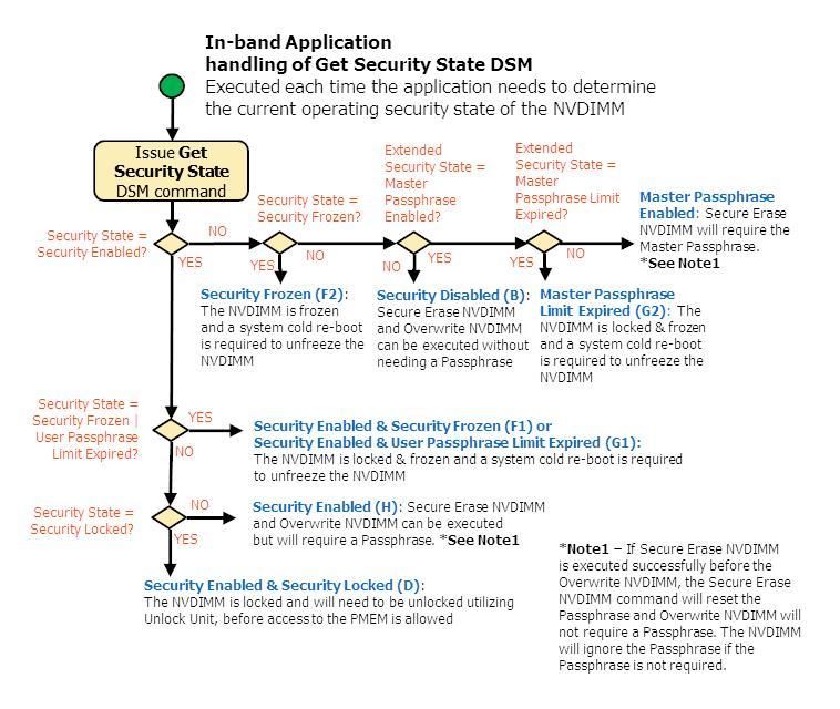
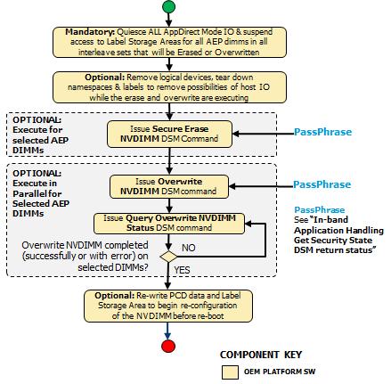
40 Application In-band Get Security State Sequence 40

41 Application In-band Secure Erase & Overwrite NVDIMM Sequence Get Security State (Function Index 19) Retrieve the current security state of the NVDIMM. Function Input None Function Output The following tables outline the expected output payload for this command. Table 3-26 Get Security State Output Format 2 0 Defined above in Table 3-C 00 Success. The security command executed successfully and the returned Security State is valid Failure Retry Suggested - Command Timed Out, Other Command In Progress, Mailbox not Ready 41
The following modifications have been made to this version of the DSM specification:
 NVDIMM DSM Interface Revision V1.6 August 9, 2017 The following modifications have been made to this version of the DSM specification: - General o Added two tables of supported Function Ids, Revision Ids
NVDIMM DSM Interface Example
 Revision 1.3 December 2016 See the change bars associated with the following changes to this document: 1) Common _DSMs supported by all NVDIMMs have been removed from this document. 2) Changes to SMART
NVDIMM Block Window Driver Writer s Guide
 NVDIMM Block Window Driver Writer s Guide Example NFIT-Based NVDIMM Block Window and Persistent Memory Interface Guide April July 20165 You may not use or facilitate the use of this document in connection
Managing Persistent Memory Tiffany Kasanicky Intel
 Managing Persistent Memory Tiffany Kasanicky Intel 1 Agenda Managing* Be in charge of; administer; run. The process of dealing with or controlling things or people. Persistent Memory Memory that retains
BIOS Implementation of UCSI
 BIOS Implementation of UCSI Technical White Paper February 2016 Revision 001 Document: 333897-001 You may not use or facilitate the use of this document in connection with any infringement or other legal
Intel Cache Acceleration Software for Windows* Workstation
 Intel Cache Acceleration Software for Windows* Workstation Release 3.1 Release Notes July 8, 2016 Revision 1.3 INFORMATION IN THIS DOCUMENT IS PROVIDED IN CONNECTION WITH INTEL PRODUCTS. NO LICENSE, EXPRESS
Clear CMOS after Hardware Configuration Changes
 Clear CMOS after Hardware Configuration Changes Technical White Paper August 2018 Revision 001 Document Number: 337986-001 You may not use or facilitate the use of this document in connection with any
Intel Desktop Board DZ68DB
 Intel Desktop Board DZ68DB Specification Update April 2011 Part Number: G31558-001 The Intel Desktop Board DZ68DB may contain design defects or errors known as errata, which may cause the product to deviate
Intel X38 Express Chipset
 Intel X38 Express Chipset Specification Update For the 82X38 Memory Controller Hub (MCH) December 2007 Document Number: 317611-002 Legal Lines and Disclaimers INFORMATION IN THIS DOCUMENT IS PROVIDED IN
Intel Solid State Drive Client PCIe* Microsoft* Windows* Driver
 Intel Solid State Drive Client PCIe* Microsoft* Windows* Driver Software 4.2.0.1002 Number: 331995-006US Intel may make changes to specifications and product descriptions at any time, without notice. Designers
Intel X48 Express Chipset Memory Controller Hub (MCH)
") Intel X48 Express Chipset Memory Controller Hub (MCH) Specification Update March 2008 Document Number: 319123-001 Legal Lines and Disclaimers INFORMATION IN THIS DOCUMENT IS PROVIDED IN CONNECTION WITH
Intel X48 Express Chipset Memory Controller Hub (MCH) Specification Update March 2008 Document Number: 319123-001 Legal Lines and Disclaimers INFORMATION IN THIS DOCUMENT IS PROVIDED IN CONNECTION WITH
Intel Solid State Drive Datacenter PCIe* Microsoft* Windows* Driver
 Intel Solid State Drive Datacenter PCIe* Microsoft* Windows* Driver Software 4.2.0.1002 Number: 331995-006US Intel may make changes to specifications and product descriptions at any time, without notice.
Reliability, Availability, Serviceability (RAS) and Management for Non-Volatile Memory Storage
 and Management for Non-Volatile Memory Storage") Reliability, Availability, Serviceability (RAS) and Management for Non-Volatile Memory Storage Mohan J. Kumar, Intel Corp Sammy Nachimuthu, Intel Corp Dimitris Ziakas, Intel Corp August 2015 1 Agenda NVDIMM
Reliability, Availability, Serviceability (RAS) and Management for Non-Volatile Memory Storage Mohan J. Kumar, Intel Corp Sammy Nachimuthu, Intel Corp Dimitris Ziakas, Intel Corp August 2015 1 Agenda NVDIMM
ACPI 6 and Linux* Rafael J. Wysocki. Intel Open Source Technology Center. August 19, 2015
 ACPI 6 and Linux* Rafael J. Wysocki Intel Open Source Technology Center August 19, 2015 Rafael J. Wysocki (Intel OTC) ACPI 6 and Linux August 19, 2015 1 / 30 Outline 1 Introduction: Overview of ACPI High
Intel Storage System JBOD 2000S3 Product Family
 Intel Storage System JBOD 2000S3 Product Family SCSI Enclosure Services Programming Guide SES Version 3.0, Revision 1.8 Apr 2017 Intel Server Boards and Systems Headline
Intel RAID Smart Battery AXXRSBBU6
 Intel RAID Smart Battery AXXRSBBU6 Technical Product Specification February 2008 Enterprise Platforms and Services Marketing Revision History Revision History Date Revision Number February 2008 1.0 initial
Intel Desktop Board DH55TC
 Intel Desktop Board DH55TC Specification Update December 2011 Order Number: E88213-006 The Intel Desktop Board DH55TC may contain design defects or errors known as errata, which may cause the product to
Intel Solid State Drive Client PCIe* Microsoft* Windows* Driver
 Intel Solid State Drive Client PCIe* Microsoft* Windows* Driver Software 3.2.0.1002 Number: 331995-006US Intel may make changes to specifications and product descriptions at any time, without notice. Designers
Intel 6400/6402 Advanced Memory Buffer
 Intel 6400/6402 Advanced Memory Buffer Specification Update October 2006 Reference Number: 313068-002 INFORMATION IN THIS DOCUMENT IS PROVIDED IN CONNECTION WITH INTEL PRODUCTS. NO LICENSE, EXPRESS OR
Intel 815 Chipset Family: Graphics and Memory Controller Hub (GMCH)
") Intel 815 Chipset Family: 82815 Graphics and Memory Controller Hub (GMCH) Specification Update May 2001 Notice: The Intel 82815 GMCH may contain design defects or errors known as errata which may cause
Intel 815 Chipset Family: 82815 Graphics and Memory Controller Hub (GMCH) Specification Update May 2001 Notice: The Intel 82815 GMCH may contain design defects or errors known as errata which may cause
Intel Desktop Board DP55SB
 Intel Desktop Board DP55SB Specification Update July 2010 Order Number: E81107-003US The Intel Desktop Board DP55SB may contain design defects or errors known as errata, which may cause the product to
Intel 848P Chipset. Specification Update. Intel 82848P Memory Controller Hub (MCH) August 2003
 August 2003") Intel 848P Chipset Specification Update Intel 82848P Memory Controller Hub (MCH) August 2003 Notice: The Intel 82848P MCH may contain design defects or errors known as errata which may cause the product
Intel 848P Chipset Specification Update Intel 82848P Memory Controller Hub (MCH) August 2003 Notice: The Intel 82848P MCH may contain design defects or errors known as errata which may cause the product
NVDIMM Overview. Technology, Linux, and Xen
 NVDIMM Overview Technology, Linux, and Xen Who am I? What are NVDIMMs? A standard for allowing NVRAM to be exposed as normal memory Potential to dramatically change the way software is written But.. They
Intel Desktop Board D945GCCR
 Intel Desktop Board D945GCCR Specification Update January 2008 Order Number: D87098-003 The Intel Desktop Board D945GCCR may contain design defects or errors known as errata, which may cause the product
Intel Desktop Board D975XBX2
 Intel Desktop Board D975XBX2 Specification Update July 2008 Order Number: D74278-003US The Intel Desktop Board D975XBX2 may contain design defects or errors known as errata, which may cause the product
DCMI Data Center Manageability Interface Specification v1.0, Revision 1.0. Addenda, Errata, and Clarifications
 DCMI Data Center Manageability Interface Specification v1.0, Revision 1.0 Addenda, Errata, and Clarifications Addendum Document Revision 1 Date: 4/21/2009 THIS SPECIFICATION IS PROVIDED "AS IS" WITH NO
Intel Desktop Board DQ35JO
 Intel Desktop Board DQ35JO Specification Update July 2010 Order Number: E21492-005US The Intel Desktop Board DQ35JO may contain design defects or errors known as errata, which may cause the product to
Intel Desktop Board DQ57TM
 Intel Desktop Board DQ57TM Specification Update December 2010 Order Number: E88215-006US The Intel Desktop Board DQ57TM may contain design defects or errors known as errata, which may cause the product
Intel Desktop Board D945GCLF
 Intel Desktop Board D945GCLF Specification Update July 2010 Order Number: E47517-008US The Intel Desktop Board D945GCLF may contain design defects or errors known as errata, which may cause the product
Intel Desktop Board D946GZAB
 Intel Desktop Board D946GZAB Specification Update Release Date: November 2007 Order Number: D65909-002US The Intel Desktop Board D946GZAB may contain design defects or errors known as errata, which may
Intel Desktop Board D945GCLF2
 Intel Desktop Board D945GCLF2 Specification Update July 2010 Order Number: E54886-006US The Intel Desktop Board D945GCLF2 may contain design defects or errors known as errata, which may cause the product
Intel Atom Processor E3800 Product Family Development Kit Based on Intel Intelligent System Extended (ISX) Form Factor Reference Design
 Form Factor Reference Design") Intel Atom Processor E3800 Product Family Development Kit Based on Intel Intelligent System Extended (ISX) Form Factor Reference Design Quick Start Guide March 2014 Document Number: 330217-002 Legal Lines
Intel Atom Processor E3800 Product Family Development Kit Based on Intel Intelligent System Extended (ISX) Form Factor Reference Design Quick Start Guide March 2014 Document Number: 330217-002 Legal Lines
Intel 7510/7512 Scalable Memory Buffer
 Intel 7510/7512 Scalable Memory Buffer June 2013 Document Number: 325123-002 Notice: This document contains information on products in the design phase of development. The information here is subject to
BIOS Update Release Notes
 PRODUCTS: DP45SG (Standard BIOS) BIOS Update Release Notes BIOS Version 0125 - SGP4510H.86A.0125.2010.0121.1927 About This Release: January 21, 2010 SATA RAID Option ROM Revision: 8.6.0.1007 LAN Option
Intel Solid State Drive NVMe* Windows* driver for the Intel Optane TM SSD 900P Series
 Intel Solid State Drive NVMe* Windows* driver for the Intel Optane TM SSD 900P Series Software 2.0.0.1024 Number: 331995-006US Intel may make changes to specifications and product descriptions at any time,
Intel SSD DC P3700 & P3600 Series
 Intel SSD DC P3700 & P3600 Series DP05 (Maintenance Release 8) Dell-PE March 2017 DP04 (MR7) Overview Intel SSD DC P3700/P3600 Series Changes from previous release: UEFI area is now populated, enabling
Intel Rack Scale Design Conformance and Software Reference Kit
 Intel Rack Scale Design Conformance and Software Reference Kit Getting Started Guide December 19, 2017 Revision 001 Document Number: 336811-001 No license (express or implied, by estoppel or otherwise)
Intel Dynamic Platform and Thermal Framework (Intel DPTF), Client Version 8.X
, Client Version 8.X") Intel Dynamic Platform and Thermal Framework (Intel DPTF), Client Version 8.X 8.1.10300.137 PV Release Release Notes March 2015 1 INFORMATION IN THIS DOCUMENT IS PROVIDED IN CONNECTION WITH INTEL PRODUCTS.
Intel Dynamic Platform and Thermal Framework (Intel DPTF), Client Version 8.X 8.1.10300.137 PV Release Release Notes March 2015 1 INFORMATION IN THIS DOCUMENT IS PROVIDED IN CONNECTION WITH INTEL PRODUCTS.
Intel Software Guard Extensions Platform Software for Windows* OS Release Notes
 Intel Software Guard Extensions Platform Software for Windows* OS Release Notes Installation Guide and Release Notes November 3, 2016 Revision: 1.7 Gold Contents: Introduction What's New System Requirements
Flash Memory Summit Persistent Memory - NVDIMMs
 Flash Memory Summit 2018 Persistent Memory - NVDIMMs Contents Persistent Memory Overview NVDIMM Conclusions 2 Persistent Memory Memory & Storage Convergence Today Volatile and non-volatile technologies
The Intel SSD Pro 2500 Series Guide for Microsoft edrive* Activation
 The Intel SSD Pro 2500 Series Guide for Microsoft edrive* Activation Solutions Blueprint January 2015 Order Number: 330880-002US INFORMATION IN THIS DOCUMENT IS PROVIDED IN CONNECTION WITH INTEL PRODUCTS.
Intel Extreme Memory Profile (Intel XMP) DDR3 Technology
 DDR3 Technology") Intel Extreme Memory Profile (Intel XMP) DDR3 Technology White Paper March 2008 Document Number: 319124-001 INFORMATION IN THIS DOCUMENT IS PROVIDED IN CONNECTION WITH INTEL PRODUCTS. NO LICENSE, EXPRESS
Intel Extreme Memory Profile (Intel XMP) DDR3 Technology White Paper March 2008 Document Number: 319124-001 INFORMATION IN THIS DOCUMENT IS PROVIDED IN CONNECTION WITH INTEL PRODUCTS. NO LICENSE, EXPRESS
Reference Boot Loader from Intel
 Document Number: 328739-001 Introduction INFORMATION IN THIS DOCUMENT IS PROVIDED IN CONNECTION WITH INTEL PRODUCTS. NO LICENSE, EXPRESS OR IMPLIED, BY ESTOPPEL OR OTHERWISE, TO ANY INTELLECTUAL PROPERTY
Intel Turbo Memory. Release Notes. October Revision
 Intel Turbo Memory Release Notes October 2008 Revision 1.8.0.1018 1B INFORMATION IN THIS DOCUMENT IS PROVIDED IN CONNECTION WITH INTEL PRODUCTS. NO LICENSE, EXPRESS OR IMPLIED, BY ESTOPPEL OR OTHERWISE,
Technical Note. SMART Command Feature Set for the eu500. Introduction. TN-FD-35: eu500 eusb SMART Commands. Introduction
 Technical Note SMART Command Feature Set for the eu500 Introduction Introduction This technical note provides the self-monitoring, analysis, and reporting technology (SMART) command (B0h) feature set for
Intel G31/P31 Express Chipset
 Intel G31/P31 Express Chipset Specification Update For the Intel 82G31 Graphics and Memory Controller Hub (GMCH) and Intel 82GP31 Memory Controller Hub (MCH) February 2008 Notice: The Intel G31/P31 Express
Open NAND Flash Interface Specification: Block Abstracted NAND
 Open NAND Flash Interface Specification: Block Abstracted NAND BA NAND Revision 1.1 8-July-2009 Hynix Semiconductor Intel Corporation Micron Technology, Inc. Numonyx Phison Electronics Corp. SanDisk Sony
Introduction to Intel Boot Loader Development Kit (Intel BLDK) Intel SSG/SSD/UEFI
 Intel SSG/SSD/UEFI") Introduction to Intel Boot Loader Development Kit (Intel BLDK) Intel SSG/SSD/UEFI Legal Disclaimer INFORMATION IN THIS DOCUMENT IS PROVIDED IN CONNECTION WITH INTEL PRODUCTS. NO LICENSE, EXPRESS OR IMPLIED,
Introduction to Intel Boot Loader Development Kit (Intel BLDK) Intel SSG/SSD/UEFI Legal Disclaimer INFORMATION IN THIS DOCUMENT IS PROVIDED IN CONNECTION WITH INTEL PRODUCTS. NO LICENSE, EXPRESS OR IMPLIED,
PCI-SIG ENGINEERING CHANGE REQUEST
 PCI-SIG ENGINEERING CHANGE REQUEST TITLE: ACPI additions for ASPM, OBFF, LTR ECNs DATE: October 30, 2009 Updated February 1, 2010 AFFECTED DOCUMENT: PCI Firmware Spec 3.0 SPONSOR: Intel Corporation Part
Capabilities and System Benefits Enabled by NVDIMM-N
 Capabilities and System Benefits Enabled by NVDIMM-N Bob Frey Arthur Sainio SMART Modular Technologies August 7, 2018 Santa Clara, CA 1 NVDIMM-N Maturity and Evolution If there's one takeaway you should
Intel Desktop Board DH61SA
 Intel Desktop Board DH61SA Specification Update December 2011 Part Number: G52483-001 The Intel Desktop Board DH61SA may contain design defects or errors known as errata, which may cause the product to
GUID Partition Table (GPT)
") GUID Partition Table (GPT) How to install an Operating System (OS) using the GUID Disk Partition Table (GPT) on an Intel Hardware RAID (HWR) Array under uefi environment. Revision 1.0 December, 2009 Enterprise
GUID Partition Table (GPT) How to install an Operating System (OS) using the GUID Disk Partition Table (GPT) on an Intel Hardware RAID (HWR) Array under uefi environment. Revision 1.0 December, 2009 Enterprise
March Getting Started with the Intel Desktop Board DQ77MK UEFI Development Kit
 March 2014 Getting Started with the Intel Desktop Board DQ77MK UEFI 2.3.1 Development Kit Getting Started with the Intel Desktop Board DQ77MK UEFI 2.3.1 Development Kit Legal Information INFORMATION IN
Intel Xeon W-3175X Processor Thermal Design Power (TDP) and Power Rail DC Specifications
 and Power Rail DC Specifications") Intel Xeon W-3175X Processor Thermal Design Power (TDP) and Power Rail DC Specifications Datasheet Addendum Revision 001 January 2019 Document Number: 338672-001 Intel products described herein. You agree
Intel Xeon W-3175X Processor Thermal Design Power (TDP) and Power Rail DC Specifications Datasheet Addendum Revision 001 January 2019 Document Number: 338672-001 Intel products described herein. You agree
Intel Desktop Board DG41CN
 Intel Desktop Board DG41CN Specification Update December 2010 Order Number: E89822-003US The Intel Desktop Board DG41CN may contain design defects or errors known as errata, which may cause the product
Intel Stress Bitstreams and Encoder (Intel SBE) 2017 AVS2 Release Notes (Version 2.3)
 2017 AVS2 Release Notes (Version 2.3)") Intel Stress Bitstreams and Encoder (Intel SBE) 2017 AVS2 Release Notes (Version 2.3) Overview Changes History Installation Package Contents Known Limitations Attributions Legal Information Overview The
Intel Stress Bitstreams and Encoder (Intel SBE) 2017 AVS2 Release Notes (Version 2.3) Overview Changes History Installation Package Contents Known Limitations Attributions Legal Information Overview The
Intel Desktop Board DH61CR
 Intel Desktop Board DH61CR Specification Update December 2011 Order Number: G27744-003 The Intel Desktop Board DH61CR may contain design defects or errors known as errata, which may cause the product to
Intel Rack Scale Design (Intel RSD) Conformance and Software Reference Kit
 Conformance and Software Reference Kit") Intel Rack Scale Design (Intel RSD) Conformance and Software Reference Kit Getting Started Guide Software v2.3.1 July 2018 Revision 002US Document Number: 337197-002US No license (express, implied, by
Intel Rack Scale Design (Intel RSD) Conformance and Software Reference Kit Getting Started Guide Software v2.3.1 July 2018 Revision 002US Document Number: 337197-002US No license (express, implied, by
Intel Solid State Drive Data Center Family for PCIe* Microsoft* Windows* Driver
 Intel Solid State Drive Data Center Family for PCIe* Microsoft* Windows* Driver Software 3.1.0.1021 Number: 331995-006US Intel may make changes to specifications and product descriptions at any time, without
Revision: 0.30 June Intel Server Board S1200RP UEFI Development Kit Firmware Installation Guide
 Revision: 0.30 June 2016 Intel Server Board S1200RP UEFI Development Kit Firmware Installation Guide Intel Server Board S1200RP UEFI Development Kit Firmware Installation Guide INFORMATION IN THIS DOCUMENT
BIOS Update Release Notes
 BIOS Update Release Notes PRODUCTS: NUC5CPYH, NUC5PPYH, NUC5PGYH (Standard BIOS) BIOS Version 0064 - PYBSWCEL.86A.0064.2017.0815.1055 Date: August 15, 2017 Option ROM: Build 1007 PC 14.34 UEFI Driver:
Intel 975X Express Chipset
 Intel 975 Express Chipset Specification Update For the Intel 82975 Memory Controller Hub (MCH) May 2006 Notice: The Intel 82975 Memory Controller Hub (MCH) may contain design defects or errors known as
Intel Desktop Board DP67DE
 Intel Desktop Board DP67DE Specification Update December 2011 Part Number: G24290-003 The Intel Desktop Board DP67DE may contain design defects or errors known as errata, which may cause the product to
Intel Solid State Drive Firmware Update Tool
 Intel Solid State Drive Firmware Update Tool Software Version 3.0.0 or later Document Number: 322570-011US Intel disclaims all express and implied warranties, including without limitation, the implied
Intel Desktop Board DG41RQ
 Intel Desktop Board DG41RQ Specification Update July 2010 Order Number: E61979-004US The Intel Desktop Board DG41RQ may contain design defects or errors known as errata, which may cause the product to
Techniques for Lowering Power Consumption in Design Utilizing the Intel EP80579 Integrated Processor Product Line
 Techniques for Lowering Power Consumption in Design Utilizing the Intel Integrated Processor Product Line Order Number: 320180-003US Legal Lines and Disclaimers INFORMATION IN THIS DOCUMENT IS PROVIDED
Intel Desktop Board DX48BT2. MLP Report. Motherboard Logo Program (MLP) 6/17/2008
 6/17/2008") Motherboard Logo Program (MLP) Intel Desktop Board DX48BT2 MLP Report 6/17/2008 Purpose: This report describes the DX48BT2 Motherboard Logo Program testing run conducted by Intel Corporation. THIS TEST
Motherboard Logo Program (MLP) Intel Desktop Board DX48BT2 MLP Report 6/17/2008 Purpose: This report describes the DX48BT2 Motherboard Logo Program testing run conducted by Intel Corporation. THIS TEST
LED Manager for Intel NUC
 LED Manager for Intel NUC User Guide Version 1.0.0 March 14, 2018 INFORMATION IN THIS DOCUMENT IS PROVIDED IN CONNECTION WITH INTEL PRODUCTS. NO LICENSE, EXPRESS OR IMPLIED, BY ESTOPPEL OR OTHERWISE, TO
Intel Desktop Board DP45SG
 Intel Desktop Board DP45SG Specification Update July 2010 Order Number: E49121-006US The Intel Desktop Board DP45SG may contain design defects or errors known as errata, which may cause the product to
Intel RealSense Depth Module D400 Series Software Calibration Tool
 Intel RealSense Depth Module D400 Series Software Calibration Tool Release Notes January 29, 2018 Version 2.5.2.0 INFORMATION IN THIS DOCUMENT IS PROVIDED IN CONNECTION WITH INTEL PRODUCTS. NO LICENSE,
BIOS Update Release Notes
 PRODUCTS: DH61AG (Standard BIOS) BIOS Update Release Notes BIOS Version 0104 - AGH6110H.86A.0104.2013.0227.1805 Date: February 27, 2013 ME Firmware: Ignition SKU 8.1.0.1248 LAN Option ROM: Intel(R) Boot
BIOS Update Release Notes
 BIOS Update Release Notes PRODUCTS: DQ57TM, DQ57TML (Standard BIOS) BIOS Version 0046 - TMIBX10H.86A.0046.2011.0722.0944 Date: July 22, 2011 Integrated Graphics Option ROM Revision on TM: 2114 PC Integrated
5 VOLT FlashFile MEMORY 28F004S5, 28F008S5, 28F016S5 (x8) SPECIFICATION UPDATE
 SPECIFICATION UPDATE") 5 VOLT FlashFile MEMORY 28F004S5, 28F008S5, 28F016S5 (x8) SPECIFICATION UPDATE Release Date: February, 1999 Order Number: 297796-007 The 28F004S5, 28F008S5, and 28F016S5 may contain design defects or errors
5 VOLT FlashFile MEMORY 28F004S5, 28F008S5, 28F016S5 (x8) SPECIFICATION UPDATE Release Date: February, 1999 Order Number: 297796-007 The 28F004S5, 28F008S5, and 28F016S5 may contain design defects or errors
NVM Express 1.3 Delivering Continuous Innovation
 Architected for Performance NVM Express 1.3 Delivering Continuous Innovation June 2017 Jonmichael Hands, Product Marketing Manager Intel, NVM Express Marketing Co-Chair View recorded webcast NVMe 1.3 -
Windows Support for PM. Tom Talpey, Microsoft
 Windows Support for PM Tom Talpey, Microsoft Agenda Industry Standards Support PMDK Open Source Support Hyper-V Support SQL Server Support Storage Spaces Direct Support SMB3 and RDMA Support 2 Windows
TCG Physical Presence Interface Specification
 TCG Physical Presence Interface Specification Specification Version 1.2 Revision 1.00 February 10 th, 2011 Contact: admin@trustedcomputinggroup.org TCG Published Copyright TCG 2003-2011 Disclaimers, Notices,
Intel Desktop Board D915GUX Specification Update
 Intel Desktop Board D915GUX Specification Update Release Date: July 2006 Order Number: C80894-005US The Intel Desktop Board D915GUX may contain design defects or errors known as errata, which may cause
Intel Desktop Board DH61SK. MLP Report. Motherboard Logo Program (MLP) 4/6/2012
 4/6/2012") Motherboard Logo Program (MLP) Intel Desktop Board DH61SK MLP Report 4/6/2012 Purpose: This report describes the DH61SK Motherboard Logo Program testing run conducted by Intel Corporation. THIS TEST REPORT
Motherboard Logo Program (MLP) Intel Desktop Board DH61SK MLP Report 4/6/2012 Purpose: This report describes the DH61SK Motherboard Logo Program testing run conducted by Intel Corporation. THIS TEST REPORT
Intel Desktop Board D915GEV Specification Update
 Intel Desktop Board D915GEV Specification Update Release Date: July 2006 Order Number: C80889-005US The Intel Desktop Board D915GEV may contain design defects or errors known as errata, which may cause
i960 VH Embedded-PCI Processor
 i960 VH Embedded-PCI Processor Specification Update November 1998 Notice: The 80960VH may contain design defects or errors known as errata. Characterized errata that may cause 80960VH s behavior to deviate
Notice for Express Report Service (MG)
") NEC Express5800, ilo Embedded Server Notice for Express Report Service (MG) Revision 1.0 Nov 22, 2017 NEC Corporation Table of Contents Table of Contents... 2 Trademarks... 3 Cautions... 3 Reference Sites...
NEC Express5800, ilo Embedded Server Notice for Express Report Service (MG) Revision 1.0 Nov 22, 2017 NEC Corporation Table of Contents Table of Contents... 2 Trademarks... 3 Cautions... 3 Reference Sites...
BIOS Update Release Notes
 BIOS Update Release Notes PRODUCTS: NUC5CPYH, NUC5PPYH, NUC5PGYH (Standard BIOS) BIOS Version 0069 - PYBSWCEL.86A.0069.2018.0314.1745 Date: March 14, 2018 TXE Firmware: 02.00.05.3117 PV Framework BIOS
Evolving Small Cells. Udayan Mukherjee Senior Principal Engineer and Director (Wireless Infrastructure)
") Evolving Small Cells Udayan Mukherjee Senior Principal Engineer and Director (Wireless Infrastructure) Intelligent Heterogeneous Network Optimum User Experience Fibre-optic Connected Macro Base stations
Evolving Small Cells Udayan Mukherjee Senior Principal Engineer and Director (Wireless Infrastructure) Intelligent Heterogeneous Network Optimum User Experience Fibre-optic Connected Macro Base stations
Intel Integrator Toolkit
 Intel Integrator Toolkit User Guide Version 6.1.8 May 4, 2018 INFORMATION IN THIS DOCUMENT IS PROVIDED IN CONNECTION WITH INTEL PRODUCTS. NO LICENSE, EXPRESS OR IMPLIED, BY ESTOPPEL OR OTHERWISE, TO ANY
Intel Desktop Board DG31PR
 Intel Desktop Board DG31PR Specification Update May 2008 Order Number E30564-003US The Intel Desktop Board DG31PR may contain design defects or errors known as errata, which may cause the product to deviate
3 VOLT FlashFile MEMORY 28F004S3, 28F008S3, 28F016S3 SPECIFICATION UPDATE. Release Date: February, Order Number:
 3 VOLT FlashFile MEMORY 28F004S3, 28F008S3, 28F016S3 SPECIFICATION UPDATE Release Date: February, 1999 Order Number: 297799-009 The 28F004S3, 28F008S3, and 28F016S3 may contain design defects or errors
Desktop/Motherboard WHC Report
 Windows Hardware Certification (WHC) Intel Desktop Board DH61AGL Desktop/Motherboard WHC Report 09/20/2012 Purpose: This report describes the DH61AGL Windows Hardware Certification testing conducted by
SFF Committee Specification for. Self-Monitoring, Analysis and Reporting Technology (S.M.A.R.T.) SFF-8035i Revision 2.0
 SFF-8035i Revision 2.0") SFF Committee Specification for Self-Monitoring, Analysis and Reporting Technology (S.M.A.R.T.) SFF-8035i Revision 2.0 April 1, 1996 This document is endorsed by Compaq Computer Corporation, Hitachi, Ltd.,
SFF Committee Specification for Self-Monitoring, Analysis and Reporting Technology (S.M.A.R.T.) SFF-8035i Revision 2.0 April 1, 1996 This document is endorsed by Compaq Computer Corporation, Hitachi, Ltd.,
Intel Rack Scale Design PSME
 Release s Software v2.2 December 19, 2017 Document Number: 336816-001 No license (express or implied, by estoppel or otherwise) to any intellectual property rights is granted by this document. Intel disclaims
User Guide. Storage Executive Command Line Interface. Introduction. Storage Executive Command Line Interface User Guide Introduction
 User Guide Storage Executive Command Line Interface Introduction Introduction This guide describes how to use Micron's Storage Executive command line interface (CLI) to monitor, manage, and configure Micron
Intel Desktop Board D845PT Specification Update
 Intel Desktop Board D845PT Specification Update Release Date: February 2002 Order Number: A83341-002 The Intel Desktop Board D845PT may contain design defects or errors known as errata which may cause
Intel True Scale Fabric Switches Series
 Intel True Scale Fabric Switches 12000 Series Doc. Number: H70235 Revision: 001US No license (express or implied, by estoppel or otherwise) to any intellectual property rights is granted by this document.
Intel E8500 Chipset North Bridge (NB)
") Intel E8500 Chipset North Bridge (NB) Specification Update June 2005 Notice: The Intel E8500 chipset North Bridge (NB) may contain design defects or errors known as errata that may cause the product to
Intel E8500 Chipset North Bridge (NB) Specification Update June 2005 Notice: The Intel E8500 chipset North Bridge (NB) may contain design defects or errors known as errata that may cause the product to
BIOS Update Release Notes
 BIOS Update Release Notes PRODUCTS: NUC5CPYH, NUC5PPYH, NUC5PGYH (Standard BIOS) BIOS Version 0058 - PYBSWCEL.86A.0058.2016.1102.1842 Date: November 02, 2016 Security Enhancements BIOS Version - PYBSWCEL.86A.0057.2016.1012.1134
Intel Entry Storage System SS4000-E
 Intel Entry Storage System SS4000-E Software Release Version 1.2: Release Notes September 2006 Storage Systems Technical Marketing Engineering Document Revision History Date Revision Number Modifications
BIOS Update Release Notes
 BIOS Update Release Notes PRODUCTS: NUC6i5SYK, NUC6i5SYH, NUC6i3SYK, NUC6i3SYH (Standard BIOS) BIOS Version 0052 - SYSKLi35.86A.0052.2016.0910.1456 Date: September 10, 2016 Fixed the issue where inserting
HPE ilo Federation User Guide for ilo 5
 HPE ilo Federation User Guide for ilo 5 Abstract This guide explains how to configure and use the HPE ilo Federation features. It is intended for system administrators, Hewlett Packard Enterprise representatives,
Intel Entry Storage System SS4000-E
 Intel Entry Storage System SS4000-E Software Release Notes January 2007 Storage Systems Technical Marketing Engineering Document Revision History Intel Entry Storage System SS4000-E Document Revision History
Windows Support for PM. Tom Talpey, Microsoft
 Windows Support for PM Tom Talpey, Microsoft Agenda Windows and Windows Server PM Industry Standards Support PMDK Support Hyper-V PM Support SQL Server PM Support Storage Spaces Direct PM Support SMB3
How to Create a.cibd File from Mentor Xpedition for HLDRC
 How to Create a.cibd File from Mentor Xpedition for HLDRC White Paper May 2015 Document Number: 052889-1.0 INFORMATION IN THIS DOCUMENT IS PROVIDED IN CONNECTION WITH INTEL PRODUCTS. NO LICENSE, EXPRESS