User manual for controller/data recorder. MultiCon CMC-99/141
|
|
|
- Darren Willis
- 5 years ago
- Views:
Transcription


1 Assisting the automation industry since 1986 User manual for controller/data recorder MultiCon CMC-99/141 Firmware: v or higher Read the user's manual carefully before starting to use the unit or software. Producer reserves the right to implement changes without prior notice MultiCon CMC-99/141_INSSXEN_v
2 CONTENTS 1. BASIC REQUIREMENTS AND USER SAFETY THE USE OF TOUCH-SCREEN GENERAL CHARACTERISTICS TECHNICAL DATA DEVICE INSTALLATION UNPACKING ASSEMBLY CONNECTION METHOD Available modules MAINTENANCE INTRODUCTION TO MULTICON CMC-99/ UNDERSTANDING CONTROLLER/DATA RECORDER MULTICON CMC-99/ Logical channels Groups HARDWARE CONFIGURATIONS WORKING WITH THE MULTICON CMC-99/ MULTICON CMC-99/141 POWER UP THE USE OF THE TOUCH-SCREEN DISPLAY Information bar Navigation bar Data panels Important messages CONFIGURATION OF THE MULTICON CMC-99/ EDIT DIALOGUES MAIN MENU SELECTION PANEL FILES MANAGEMENT DEVICE INFORMATION, LICENSE AND FIRMWARE UPDATE DEVICE CONFIGURATION CONFIGURATION MENU STRUCTURE GENERAL SETTINGS LOGICAL CHANNELS Logical Channels - general settings Logical channels in Hardware input mode Logical Channels in Hardware output monitor mode Logical Channels in Modbus mode Logical Channels settings for Set point value mode Logical Channels settings for Math function mode Logical Channels settings for Controller mode Logical Channels settings for Profile/timer mode Logical Channels for Profile/timer (cycle counter) mode Examples of Logical Channels configuration BUILT-IN OUTPUTS Build-in outputs - general settings Built-in Output: Relay, Sound signal, Virtual relay Build-in output: PWM mode for SSR relay output Build-in output - Current output Examples of build-in output configurations EXTERNAL OUTPUTS External outputs - general settings External outputs - Control type = as a relay External outputs - Control type = as a linear output Examples of external output configurations PROFILES/TIMERS Profile/timer - general settings
3 Profiles/timers for triggering mode: level (gate), edge (once), edge (retrig.) Profiles/timers for triggering mode: on time Examples of Profile/timer configurations CONTROLLERS Controllers - general settings Examples of Controller configurations GROUPS Groups - general settings Groups - Logging options Groups - Examples of visualisations of groups MODBUS Modbus - general settings Modbus - SLAVE mode Modbus SLAVE - The Modbus protocol handling Modbus SLAVE - List of registers Modbus SLAVE- Transmission errors handling Modbus SLAVE- Example of query/answer frames Modbus - MASTER mode Modbus MASTER - Device templates parameter block Modbus MASTER- Device channels parameter block Modbus MASTER- Register blocks parameter block Modbus - Register settings Modbus - Example of Modbus protocol configuration in the device NETWORK SETTINGS ACCESS OPTIONS APPENDIX - INPUT AND OUTPUT MODULES DESCRIPTION PS3, PS4 - POWER SUPPLY MODULE UI4, UI8, U16, I16, FI4 - VOLTAGE, CURENT AND FLOW MEASUREMENT MODULES TC4, TC8 THERMOCOUPLE SENSOR MEASUREMENT MODULES RT4 RTD MEASUREMENT MODULE UN3 OPTOISOLATED UNIVERSAL INPUT MODULE D8, D16 OPTOISOLATED DIGITAL INPUT MODULE CP4 OPTOISOLATED UNIVERSAL COUNTER MODULES S8, S16 - SOLID STATE RELAY DRIVERS MODULES R45, R81 - RELAY MODULES IO2, IO4 PASSIVE CURRENT OUTPUT COMMUNICATION MODULES Explanation of symbols used in the manual:! - This symbol denotes especially important guidelines concerning the installation and operation of the device. Not complying with the guidelines denoted by this symbol may cause an accident, damage or equipment destruction. IF THE DEVICE IS NOT USED ACCORDING TO THE MANUAL THE USER IS RESPONSIBLE FOR POSSIBLE DAMAGES. i - This symbol denotes especially important characteristics of the unit. Read any information regarding this symbol carefully 3
4 1. BASIC REQUIREMENTS AND USER SAFETY! - The manufacturer is not responsible for any damages caused by inappropriate installation, not maintaining the proper environmental conditions and using the unit contrary to its assignment. - Installation should be conducted by qualified personnel. During installation all available safety requirements should be considered. The fitter is responsible for executing the installation according to this manual, local safety and EMC regulations. - input of device should be connected to PE wire; - The unit must be properly set-up, according to the application. Incorrect configuration can cause defective operation, which can lead to unit damage or an accident. - If in the case of a unit malfunction there is a risk of a serious threat to the safety of people or property additional, independent systems and solutions to prevent such a threat must be used. - The unit uses dangerous voltage that can cause a lethal accident. The unit must be switched off and disconnected from the power supply prior to starting installation of troubleshooting (in the case of malfunction). - Neighbouring and connected equipment must meet the appropriate of appropriate standards and regulations concerning safety and be equipped with adequate overvoltage and interference filters. - Do not attempt to disassemble, repair or modify the unit yourself. The unit has no user serviceable parts. Defective units must be disconnected and submitted for repairs at an authorized service centre.! - In order to minimize fire or electric shock hazard, the unit must be protected against atmospheric precipitation and excessive humidity. - Do not use the unit in areas threatened with excessive shocks, vibrations, dust, humidity, corrosive gasses and oils. - Do not use the unit in areas where there is risk of explosions. - Do not use the unit in areas with significant temperature variations, exposure to condensation or ice. - Do not use the unit in areas exposed to direct sunlight. - Make sure that the ambient temperature (e.g. inside the control box) does not exceed the recommended values. In such cases forced cooling of the unit must be considered (e.g. by using a ventilator).! 4 The unit is designed for operation in an industrial environment and must not be used in a household environment or similar.
5 1.1. THE USE OF TOUCH-SCREEN Do not use pointers with sharp edges (like tips of pencils and pens, knifes, scissors, needles, wires, nails, bolts etc.) while working with touch-screen. It is strongly recommended to use a special stylus made of plastic or another soft material with round ends (for example the stylus delivered with the device). The display of the MultiCon CMC-99/141 should also be protected against aggressive substances and extremely high and low temperatures (see Chapter 3. TECHNICAL DATA). 2. GENERAL CHARACTERISTICS The MultiCon CMC-99/141 is a sophisticated multichannel unit which allows simultaneous measurement, visualisation and control of numerous channels. This device can operate autonomously or with cooperation with external measurement devices and actuators. Essential features of MultiCon CMC-99/141 are listed and briefly described below. Advanced processing unit and system based on LINUX The powerful MultiCon CMC-99/141 processor allows the device to run under the control of a LINUX operating system. Such a solution makes the firmware flexible and gives the possibility of simultaneous operation of many processes (like: measurement, communication, visualisation). The use of LINUX also makes software independent of installed hardware. Colour TFT display with Touch-panel The MultiCon CMC-99/141 displays all data and dialogue on a legible, 320x240 pixels, colour TFT screen. Full control of the device is realised using the built-in touch-panel which makes operating the MultiCon CMC-99/141 easy and intuitive. Hardware flexibility and a large variety of possible configurations MultiCon CMC-99/141 is designed as modular device consisting of a base and optional input and output modules. The base contains: main processor, display with touch-screen, Switch Mode Power Supply 19V V DC, 16V V AC 85V V, basic communication interfaces (USB and RS485). three slots (marked as A, B, C) designed for installation of measurement and/or output modules. one slot (marked as D) used for advanced communication module (additional USB Host, RS-485, RS-485/RS-232 and Ethernet). All measurement and output modules are optional and can be installed inside the device according to the customer's needs. Input modules that can be installed: 4/8/16x Voltage/Current input module, 4x RTD input module, 4/8x TC input module, 8/16x Optoisolated digital input, 3x universal input module, 5
6 4x universal counter module, 4x flowmeter input + 4x current input module. Output modules that can be installed: 8/16x SSR driver module, 4x Relay module 5A/250V, 8x Relay module 1A/250V, 2/4x Passive current output module. Full freedom of data sources, presentation modes and controlling methods The multi level structure of the MultiCon CMC-99/141 firmware allows for selection of presented data sources, presentation modes and controlling methods. The MultiCon CMC-99/141 displays the values of virtual logical channels which can be fed with: measurement data from built-in physical channels, measurement data from remote channels (other devices connected to the MultiCon CMC-99/141 by RS-485 interface), output states and quantities (looped back results of controlling processes), generate profiles/timers or also the mathematical combination of one or more logical channels. Build-in analog input Buid-in binary input External input (RS-485) Profiles/timers Controller Mathematical & logical combination data States of hardware & virtual outputs Set point values Interface Display Charts & bars Needles indicators Interface Numeric, logical or text values Reading data via Ethernet Reading data stored on the flash drive Grouping data Interface Build-in analog output Build-in binary output External output (RS-485) Fig Basic structure of the multichannel device 6
7 All of these can be freely named and described by the user, and presented in many forms: as numerical values, vertical and horizontal charts, vertical and horizontal bars, as needle graphs. Every logical channel (visualised or not) can be used as input data for one or more controlling process. The MultiCon CMC-99/141 implements many different controlling methods: above defined level, below defined level, inside defined range, outside of defined range PID control. Process control with built-in outputs can be done with programmable hysteresis and delays of the outputs control. It is possible to control (linearly or bistably) remote modules. Controlling processes can drive built-in physical outputs or virtual outputs which can be used as inputs to logical channels. 7
8 3. TECHNICAL DATA Power supply voltage (depending on version) External Fuse (required) Power consumption V AC/DC; Hz or V DC; 16V V AC T - type, max. 2 A typically 15 VA; max. 20 VA Display (depending on version) 3.5 or 5.7, TFT colour graphic display, 320 x 240 pixels, with LED backlight Sensor power supply output 24V DC ± 5% / max. 200 ma, Basic communication interfaces RS 485, 8N1/2, Modbus RTU, 1200 bit/s bit/s USB Host port, USB Device port Digital input 1 input 0/15..24V DC, galvanic insulation (low state: 0 5V, high state:8 24V) power consumption: 7,5 ma / 24V, insulation: 500V DC. Optional communication module* Second USB Host port Serial RS-485 and RS-485/RS-232 Ethernet 10M RJ-45 Optional input modules* 4/8/16x Voltage (0 10V) / Current (0 20mA)** 4x RTD (Pt100, Pt500, Pt1000, Cu50, Cu100)** 4/8x TC (J, K, S, T, N, R, B, E, L(GOST)** 8/16x Digital input** 3x Universal input** 4x Universal counter** 4x flowmeter + 4x Current** Optional output modules* 4x Relay 5A/250V (cos ϕ = 1)** 8x Relay 1A/250V (cos ϕ = 1)** 8/16x SSR driver (10 15V, up to 100mA per output)** 2/4x IO Passive current output (4 20mA)** Protection level USB interface on rear panel IP 65 (from front, after using waterproof frame) IP 54 (from front, with transparent door) IP 40 (from front, standard) IP 20 (housing and connection clips) USB interface from front IP 54 (from front, with transparent door) IP 40 (from front, standard) IP 20 (housing and connection clips) Housing type Housing material panel NORYL - GFN2S E1 Housing dimensions 96 x 96 x 100 mm (small housing) or 145 x 145 x 100 mm (big housing) Mounting hole 90.5 x 90.5 mm (small housing) or 137 x 137 mm (big housing) 8
9 Assembly depth Panel thickness 102 mm max. 5 mm Operating temperature Storage temperature Humidity Altitude 0 C to +50 C -10 C to +70 C 5 to 90% no condensation up to 2000 meters above sea level Screws tightening max. torque Max. connection leads diameter Safety requirements 0,5 Nm 2,5 mm2 according to: PN-EN installation category: II pollution degree: 2 voltage in relation to ground: 300V AC insulation resistance: >20MΩ insulation strength between power supply and input/output terminal: 2300V (see Fig. 4.1) PN-EN EMC Weight 340g (only base, see Fig. 4.8) * check the current list of measurement modules at producer's website ** see the full specification in the appendix 4. DEVICE INSTALLATION The unit has been designed and manufactured in a way assuring a high level of user safety and resistance to interference occurring in a typical industrial environment. In order to take full advantage of these characteristics installation of the unit must be conducted correctly and according to the local regulations.! - Read the basic safety requirements on page 4 prior to starting the installation. - Ensure that the power supply network voltage corresponds to the nominal voltage stated on the unit s identification label. - The load must correspond to the requirements listed in the technical data. - All installation works must be conducted with a disconnected power supply. - Protecting the power supply connections against unauthorized persons must be taken into consideration.!! This is a class A unit. In a residential or a similar area it can cause radio frequency interference. In such cases the user can be requested to use appropriate preventive measures. Carefully check that the insulation used with the unit (Fig. 4.1) meets the expectations and if necessary use appropriate measures of over voltage protection. Additionally, insure the appropriate air and surface insulation gaps when installing. 9
10 External sensor supply output Measurement inputs RS 485 interface and digital input Internal circuits Power supply Outputs circuits Insulation strength 2300V AC Insulation strength 500V AC No insulation Fig Schematic diagram showing the insulation between individual circuits of the unit UNPACKING After removing the unit from the protective packaging, check for transportation damage. Any transportation damage must be immediately reported to the carrier. Also, write down the unit serial number located on the housing and report the damage to the manufacturer. Attached with the unit please find: assembly brackets - 2 pieces, warranty, user s manual for MultiCon CMC-99/141 unit (device) 4.2. ASSEMBLY! - The unit is designed for mounting inside housings (control panel, switchboard) insuring appropriate protection against surges and interference. Metal housings must be connected to ground in a way that complies with the governing regulations. - Disconnect the power supply prior to starting assembly. - Check the connections are wired correctly prior to switching the unit on. In order to install the unit, a mounting hole must be prepared according to Fig The thickness of the material of which the panel is made must not exceed 5mm. When preparing the mounting hole take the grooves for catches located on both sides of the housing into consideration (Fig. 4.2). Place the unit in the mounting hole inserting it from the front side of the panel, and then fix it using the brackets 10
11 (Fig. 4.4). The minimum distances between the center points of multiple units - due to the thermal and mechanical conditions of operation - are shown on Fig W Small housing: H, W = 90.5 mm h = 16 mm h 8 mm Big housing: H, W = 137 mm h= 38.5 mm H 8 mm h 1 mm 1 mm max. 5 mm Fig Mounting hole dimensions W Big housing: H, W = 165 mm H Small housing: H, W = 115 mm Fig Minimum distances when assembly of a number of units 11
12 98 mm 8 mm removable terminals Fig Installing of brackets To avoid connectors slots destruction use the method shown on Fig. 4.5 GOOD back side of device connector WRONG back side of device connector Fig Connectors removing method 12
13 4.3. CONNECTION METHOD Caution! - Installation should be conducted by qualified personnel. During installation all available safety requirements should be considered. The fitter is responsible for executing the installation according to this manual, local safety and EMC regulations. - The unit is not equipped with an internal fuse or power supply circuit breaker. Because of this an external time-delay cut-out fuse with a small nominal current value must be used (recommended bipolar, max. 2A) and a power supply circuitbreaker located near the unit. In the case of using a monopolar fuse it must be mounted on the active wire (L). - The power supply network cable diameter must be selected in such a way that in the case of a short circuit of the cable from the side of the unit the cable shall be protected against destruction with an electrical installation fuse. - Wiring must meet appropriate standards and local regulations and laws. - In order to secure against accidental short circuit the connection cables must be terminated with appropriate insulated cable tips. - Tighten the clamping screws. The recommended tightening torque is 0.5 Nm. Loose screws can cause fire or defective operation. Over tightening can lead to damaging the connections inside the units and breaking the thread. - In the case of the unit being fitted with separable clamps they should be inserted into appropriate connectors in the unit, even if they are not used for any connections. - Unused terminals (marked as n.c.) must not be used for connecting any connecting cables (e.g. as bridges), because this can cause damage to the equipment or electric shock. - If the unit is equipped with housing, covers and sealing to protecting against water intrusion, pay special attention to their correct tightening or clamping. In the case of any doubt consider using additional preventive measures (covers, roofing, seals, etc.). Carelessly executed assembly can increase the risk of electric shock. - After the installation is completed do not touch the unit s connections when it is switched on, because it carries the risk of electrical shock. 13
14 Due to possible significant interference in industrial installations appropriate measures assuring correct operation of the unit must be applied. To avoid the unit of improper indications keep recommendations listed below. N 1 L 2! N FUSE L Depending on version: V AC/DC or V DC; V AC Fig Connection of power supply Avoid running signal cables and transmission cables together with power supply cables and cables controlling inductive loads (e.g. contactors). Such cables should cross at a right angle. Contactor coils and inductive loads should be equipped with interference protection systems, e.g. RC-type. Use of screened signal cables is recommended. Signal cable screens should be connected to the earthing only at one of the ends of the screened cable. In the case of magnetically induced interference the use of twisted pair signal cables is recommended. Twisted pair (best if shielded) must be used with RS-485 serial transmission connections. In the case of measurement or control signals are longer than 30m or go outside of the building then additional safety circuits are required. In the case of interference from the power supply side the use of appropriate interference filters is recommended. Bear in mind that the connection between the filter and the unit should be as short as possible and the metal housing of the filter must be connected to the earth with the largest possible surface. The cables connected to the filter output must not be run with cables with interference (e.g. circuits controlling relays or contactors). max. 1.5 mm Connections of power supply voltage and measurement signals are executed using the screw connections on the back of the unit s housing. 5-6 mm Fig Method of cable insulation replacing and cable terminals dimensions! 14 All connections must be made while power supply is disconnected!
15 Slot D Slot C Slot B Slot A 1 2 Power supply (depending on version) USB device V DC ±5% Imax. = 200mA BA+ digital input 0/15..24V DC RS-485 insulated Fig Terminals description The basic performance of the device (see Fig. 4.8) contains only the extreme left terminals: Power supply, USB device port, Sensor supply output +24V DC Imax=200mA, Digital input 0V V DC (low state: 0 5V, high state:8 24V) Interface RS-485, i In case of UN3 module installed, there is no +24V DC output and this terminal stay not connected. This limitation is temporary and will be removed soon. Depending on customer's needs, the basic version of the device can be upgraded with up to: three I / O modules (installed in a place designated as Slot A, Slot B Slot C), advanced communication module (additional serial, USB and Ethernet interfaces). According to the order these terminals can look different than shown in Fig. 4.8 or be not present. Terminals and connections of available modules are shown on Fig Shown below is an example of a configuration of the installed modules: base, Slot A - UI8 module (8 current input & 8 voltage input), Slot B - RT4 module (4 RTD input), Slot C - R81 module (8 relay output 1A/250V), Slot D - ACM module (additional serial, USB and Ethernet interfaces). 15
16 Available modules AIN9 AIN10 AIN11 n06 n07 n08 n09 n10 AIN4 n06 n07 n08 n09 n10 AIN5 AIN6 AIN7 AIN8 n11 n12 n13 n14 n15 AIN12 AIN13 n16 n17 n18 n19 n20 AIN14 AIN15 AIN16 n06 n07 n08 n09 n10 AIN5 AIN6 AIN7 AIN8 AIN9 AIN10 AIN11 AIN12 AIN13 AIN14 AIN15 AIN16 n11 n12 n13 n14 n15 n16 n17 n18 n19 n20 Fig Available current and voltage input modules FI4 n06 n07 n08 n09 n10 AIN1 AIN2 AIN3 AIN4 AIN5 AIN6 AIN7 AIN8 4 x 0-20mA n01 n02 n03 n04 n05 4 x 0-20mA (flowmeters) 4 flowmeter inputs + 4 current inputs Fig Available flowmeter modules 16 4 x 0-10V AIN4 AIN1 AIN2 AIN3 AIN4 AIN5 4 x 0-10V AIN8 AIN3 AIN3 n01 n02 n03 n04 n05 AIN6 AIN7 AIN8 AIN9 4 x 0-10V AIN7 AIN2 AIN2 16 voltage inputs AIN10 AIN11 AIN12 AIN13 4 x 0-10V AIN6 AIN1 AIN1 4 x 0-20mA AIN5 4 x 0-20mA n01 n02 n03 n04 n05 4 x 0-20mA AIN4 4 current + 4 voltage inputs n01 n02 n03 n04 n05 4 x 0-20mA n16 n17 n18 n19 n20 AIN3 UI4 4 x 0-10V n11 n12 n13 n14 n15 AIN2 4 x 0-10V n06 n07 n08 n09 n10 AIN1 4 x 0-10V n01 n02 n03 n04 n05 U16 4 x 0-20mA 16 current inputs 4 x 0-20mA I16 8 current + 8 voltage inputs 4 x 0-20mA UI8 AIN14 AIN15 AIN16
17 UN3 3 universal inputs - TC, mv + RTD AIN1 + V, ma TC, mv + RTD AIN2 + + TC, mv + RTD AIN3 n01 n02 n03 n04 n05 n06 n07 n08 n09 n10 n11 n12 n13 n14 n15 Fig Available universal input modules TC4 4 thermocouple inputs n09 n10 n11 n12 n13 n14 n15 n16 AIN2 AIN3 n05 n06 n07 n08 AIN4 n01 n02 n03 n04 AIN1 RT4 4 RTD inputs TC8 8 thermocouple inputs n01 n02 + AIN1 n01 n02 + AIN1 n03 n04 + AIN2 n03 n04 + AIN2 - - n05 n06 + AIN3 n05 n06 + AIN3 n07 n08 + AIN4 n07 n08 + AIN4 n09 n10 + AIN5 n11 n12 + AIN n13 n14 + AIN7 n15 n16 + AIN8 - Fig Available RTD and TC input modules 17
18 CP4 4 universal counters n01 n02 n03 n04 n05 n06 n07 n08 n09 n10 n11 n12 n13 n14 n15 n16 n17 n18 n19 n20 Inp11 Inp12 Prg1 Counter 1 Res1 COM1 Inp21 Inp22 Prg2 Counter 2 Res2 COM2 Inp31 Inp32 Prg3 Counter 3 Res3 COM3 Inp41 Inp42 Prg4 Res4 COM4 Counter 4 D16 16 Digital inputs D8 8 Digital inputs n01 n02 n03 n04 n05 n06 n07 n08 n09 n10 n11 n12 n13 n14 n15 n16 n17 n18 n19 n20 n01 n02 n03 n04 n05 n06 n07 n08 n09 n10 DIN1 DIN2 DIN3 DIN17 DIN4 COM 1-4 DIN5 DIN6 DIN7 DIN18 DIN8 COM 5-8 DIN21 DIN1 DIN2 DIN3 DIN4 COM 1-4 DIN11 DIN6 DIN7 DIN8 COM 5-8 DIN19 DIN12 COM 9-12 DIN13 DIN14 DIN15 DIN20 DIN16 COM Fig Available Counters and Digital input modules 18 DIN11 DIN5 DIN9 DIN10 DIN9 DIN10
19 S16 16 SSR outputs R81 8 relay outputs 1A/250V n09 n10 n11 n13 R1 n04 n05 n06 n11 n12 n13 n14 n15 n08 n09 n10 R8 R7 n12 n06 n07 n08 n09 n10 n07 R6 R5 n08 R4 n07 n02 R2 n06 R3 n05 n01 n03 n16 n17 n18 n19 n20 n11 n V DC n01 n02 n03 n04 n05 R3 n04 R2 n03 R45 4 relay outputs 5A/250V R4 n02 R1 n01 n14 SSR1 SSR2 SSR3 SSR4 SSR5 SSR6 SSR7 SSR8 S8 8 SSR outputs n01 n02 n03 n04 n05 n06 n07 n08 n09 n V DC SSR1 SSR2 SSR3 SSR4 SSR5 SSR6 SSR7 SSR V DC SSR9 SSR10 SSR11 SSR12 SSR13 SSR14 SSR15 SSR16 Fig Available output modules n07 n08 AOUT 3 AOUT 2 n05 n06 PASSIVE n05 n06 AOUT 4 AOUT 2 AOUT 1 n07 n08 PASSIVE n03 n04 PASSIVE n01 n02 PASSIVE 2 current output PASSIVE IO2 4 current output PASSIVE IO4 AOUT 1 Fig Available passive current output 19
 RS-232 / RS-485 converter (SRS-2/4-Z45) 20")
20 RS RS-485 insulated insulated RS RS (2) B- (2) A+ (2) RS (3) B- (3) A+ (3) RS (3) RxD (3) TxD (3) CTS (3) RTS (3) USB host RJ-45 ETH RS-485 Fig ACM communication module BA+ RS232/RS485 or USB/RS485 interface Fig Connection of RS-485 transmission signals The MultiCon CMC-99/141 device supports the following converters: USB / RS-485 converter (SRS-USB/4-Z45) RS-232 / RS-485 converter (SRS-2/4-Z45) 20
21 4.4. MAINTENANCE The unit does not have any internal replaceable or adjustable components available to the user. Pay attention to the ambient temperature in the room where the unit is operating. Excessively high temperatures cause faster ageing of the internal components and shorten the fault-free time of the unit's operation. In cases where the unit gets dirty do not clean with solvents. For cleaning use warm water with small amount of detergent or in the case of more significant contamination ethyl or isopropyl alcohol.! Using any other agents can cause permanent damage to the housing. Product marked with this symbol should not be placed in municipal waste. Please check local regulations for disposal of electronic products. 5. INTRODUCTION TO MultiCon CMC-99/ UNDERSTANDING CONTROLLER/DATA RECORDER MultiCon CMC-99/141 The MultiCon CMC-99/141 device was developed as a universal multichannel controller. To maintain this concept its firmware was written with multi level structure. The device runs under the control of a LINUX operating system keeping all subsystems ready to use and allowing independent and simultaneous operation of many processes (communication, data acquisition, post-processing, visualisation etc.). Such an approach gives great advantages to high level applications, making it flexible and dynamically configurable. Similarly data structures and streams were implemented in quite a different way than in most similar devices. The main difference is the concept of using Logical Channels as a bridge: physical inputs and outputs - visualisation and controlling processes. Designers of MultiCon CMC-99/141 decided to use such solution to increase functionality of the device and make software near fully independent on the hardware Logical channels A Logical Channel is a data stream existing in the memory of the device, having it's own name and can be displayed in almost any way. Logical Channels can be used as: measurement inputs, data source of control loop, control source of the physical outputs, input data to other Logical Channels, data source for visualisation and logging. 21
22 Hardware input Built-in output Bi Ai X2 X3 X4 X5 Digital input Analog input Digital input 24V Virtual demo input (sinus, tringle, rectangular) Rel X1 V1 V2... V16 Logical channel LC Output monitor Rel X1 V1 V2... V16 Relays Sound signal Virtual relay Modbus port address Modbus input MP input Set point value Value output F Sound signal Virtual relay External output address port Remote 1 Modbus... 2 output MP 255 Groups Group Slot Visualization & logging (optional)... G Profile/timer 1 2 Profile/timer... P/t Math function Function Relay Controller C Controller Fig The overall connections structure of the Logical channel with the device I /O Fig. 5.1 shows general structure of of connections between logical channels, and device inputs/outputs. Each of Logical Channels can be configured to represent: measurement data from built-in physical input channels, output data and states of physical output channels, output data and states of external modules connected to MultiCon CMC-99/141 via RS-485 interface, states and data coming from outputs of controlling processes, generated profile/timer states of virtual input channels, and timers, mathematical combination of other Logical Channels. 22

23 More information about Logical channels and samples of configuration Logical channels are presented in Chapter 7.8 LOGICAL CHANNELS. To make visualization clearer Logical Channels can be gather into Groups Groups A Group is a set of 1-6 Logical Channels. The MultiCon CMC-99/141 can show on the same screen only channels belonging to the same Group, additionally each Group has its own individual name making operation with the device very clear. Every Logical Channel can belong to one or more groups simultaneously, and also not to belong to any group (then it will not be shown, but it can still be used for other processes). It is common that channels belonging to the same Group are related to one another in some way (for example representing parameters of single object or representing similar parameters of few separate objects) but it is also possible to create a Group consisting of completely unrelated channels. Logical channels Groups 1 Visualization and logging Fig An overview of the concept of Group in the device Using Groups, Logical Channels and mathematical combinations of them gives incredible flexibility to the software, allowing for ease in designing advanced control methods and visualisation with a low cost MultiCon CMC-99/141. More information about Groups and samples of Group configurations are presented in Chapter 7.13 GROUPS HARDWARE CONFIGURATIONS The functionality of MultiCon CMC-99/141 can fit to the user's needs. The base of the MultiCon CMC-99/141 contains: the main processor, display with touch-screen, Switch Mode Power Supply (in one of two versions: 19V V DC 16V V AC and 85V V AC) and basic communication interfaces like USB and RS485. See Fig most far left connectors. All other modules are optional and can be installed inside the device according to 23
24 customer's needs. Next to the basic connectors is the slot for an advanced communication module. In the simplest version this module can be equipped only with rear USB Host connector (this is standard for the IP-65 version of the MultiCon CMC-99/141). The full version of this module contains also 2 additional serial ports (RS485 and RS485/RS232) and a 10Mb Ethernet RJ-45 connector (see Fig. 4.16). Three slots designed for built-in hardware inputs and outputs are installed on the right side of the case (see Fig. 4.8, terminals marked: slot A, slot B and slot C). The number and size of these terminals varies depending on module type. Brief descriptions of available modules are shown in Fig Measurement and actuator modules are constantly being developed, so the current list of available modules varies (visit manufacturers website to check current list of MultiCon CMC-99/141 modules). Basic measurement modules are: 4/8/16x Voltage/Current input module, 4x RTD input module, 4/8x TC input module. Output modules are: 8/16x SSR driver module, 8x Relay 1A/250V module, 4x Relay 5A/250V module, 2/4x IO passive current output. Communication module: ACM - advanced communication module. 6. WORKING WITH THE MultiCon CMC-99/ MultiCon CMC-99/141 POWER UP After powering up a starting Logo is showed on the MultiCon CMC-99/141 display. While the operating system is being loaded a progress bar is visible in the middle of the screen. During this process the view of screen may stay dimmed for 3-5 seconds. Please wait until the end of this operation before starting to operate the device. After that the main application is started. The view of the main program depends of the General settings (see the Chapter 7.8.1Logical Channels - general settings) and Group settings (see Chapter 7.13 GROUPS). An example view of the main program shown in Fig THE USE OF THE TOUCH-SCREEN Do not use pointers with sharp edges (like tips of pencils and pens, knifes, scissors, needles, wires, nails, bolts etc.) while working with touch-screen. It is strongly recommended to use a special stylus made of plastic or another soft material with round ends (for example the stylus delivered with the device) or a finger. The display of the MultiCon CMC-99/141 should also be protected against aggressive substances and extremely high and low temperature(see technical data in Chapter 3 TECHNICAL DATA). i 24 To clean the LCD screen you should use a special detergent designed for LCDs and a soft cloth.
25 6.3. DISPLAY The MultiCon CMC-99/141 displays all data and dialogue on a 3,5 320x240 pixel, colour TFT screen with embedded touch screen panel. New devices have the display protected with a thin transparent plastic cover. This protective layer should be removed before use to ensure perfect visibility of pictures and sensitivity of the touch-screen. While normal operation the MultiCon CMC-99/141 displays data in a form selected by user, at any time it is possible to switch presentation mode and group or show configuration menu. All details of the user interface are designed to make use of device easy and intuitive. To change display mode, group or to enter the menu, touch the screen of the MultiCon CMC99/141 and press appropriate button in the Navigation bar. i Further information about menu and presentation modes are described in further chapters. Information bar Chapter Data panels Chapter Navigation bar Chapter Fig Typical view of a MultiCon CMC-99/141 main page, after touching display Information bar The Information bar informs the user about current, display group, logging, actual date and time. name of the group which is visible on the display date group number logging data indicator time Fig View of information bar 25

26 Information bar displays (Fig. 6.2): name of the Group visible on the screen, in place of standard name (e.g. Group 4). It is possible to enter a more descriptive name for clarity (for more information see Chapter GROUPS), group number - number of the currently displayed Group, to change the displayed Group press button [ GROUP] or [GROUP ] in the Navigation bar (see Chapter Navigation bar), time and date - actual time and date display on the right upper corner on the screen can be set in General settings (see Chapter 7.7. GENERAL SETTINGS), logging data indicator - located in the Information bar the logging data indicator changes color depending of state logging: gray color - data logging option is not activated (to activate data logging option you need to enter the licence key provided by manufacturer - see Chapter 7.4. DEVICE INFORMATION, LICENSE AND FIRMWARE UPDATE), green color - after activation the data logging option indicator changes to green both when the data logging is enabled and when it is disabled (for more information about setting data logging see Chapter Groups - Logging options), yellow color - possibility to logging data in the device with additional information that there is only 10MB of free memory remaining (to clear the memory you need to move onto a removable flash drive any important data logging files and possibly the Modbus templates, after which remove them from the device - more information see Chapter 7.3. FILES MANAGEMENT), red color - warning about the lack of space on memory card, meaning data logging would not be possible until space is freed in the memory (how to remove data and exchange data with a flash drive is shown in Chapter 7.3. FILES MANAGEMENT) alternately blinking green with a blue color - when the indicator flashes blue the logged data is moved to memory (Note! at this time you must not turn off the device because it may cause a loss of recently logging data).! In order to turn off the device especially when the data logging is ON it is recommended to use the safe-off device by pressing the button Safe-shutdown in the main menu (see Fig. 7.14) Navigation bar The touching the screen at any place causes the Navigation bar to display(see Fig. 6.3) which allows the user to switch between visualisation modes, groups and to enter the menu. Fig Main window of device displaying the Navigation bar 26
27 This bar contains three kinds of buttons: switching between visualisation modes of current group (for possible modes see Chapter Data panels and Chapter GROUPS) entering the main menu (see details in Chapter 7. CONFIGURATION OF THE MultiCon CMC-99/141) switching between presented groups of logical channels (activation and settings for Group view see Chapter 7.13 GROUPS) i To enter directly into the configuration menu of particular Logical channel, press and hold screen over the channel data panel for 3-4 seconds (see option (1) in the Fig. 6.4 entering configuration of the logical channel named 'Temperature'). Similarly to go directly to configuration of displayed Group, touch and hold the group number or group name in the upper Information bar for a few seconds (see option (2) in the Fig. 6.4 entering configuration of the Group named 'Group 4'). In both cases if a password is set (see Chapter ACCESS OPTIONS) then the user has to enter the password before entering the configuration. 2 1 Fig Methods for direct entry to Logical channel configuration (1) and Group configuration (2) Data panels The great deal of the screen is being used for channel visualisation. Data can be presented in one of the following modes: as numerical values, as charts, as bars, as needle dials. All channels of the current group are simultaneously presented in the same mode. In the current version of software there is no possibility to mix different modes in one view. Figures show examples of different views. The switching between visualisation modes can be done by pressing the buttons [MODE ] or [MODE ] in the Navigation bar (see Chapter 27
![6.3.2. Navigation bar). Switching between groups can be done by pressing the buttons [GROUP ] or [GROUP ]. 4 3 1 5](/docs-images/93/112545168/images/28-0.jpg "2 Fig. 6.5. View of the Data panel In all data panels (a sample of a data panel is shown inside the frame marked (1) in Fig. 6.5) the following information is available: value of the logical channel (denoted by (2) in Fig.")
28 Navigation bar). Switching between groups can be done by pressing the buttons [GROUP ] or [GROUP ] Fig View of the Data panel In all data panels (a sample of a data panel is shown inside the frame marked (1) in Fig. 6.5) the following information is available: value of the logical channel (denoted by (2) in Fig. 6.5), data unit (denoted by (3)), channel's name (denoted by (4)), on some modes there is also a visible percentage indicator of the value in relation to it's full scale (denoted by (5)), Every Group of Logical Channels can be presented in one of 6 modes: as numerical values Fig. 6.6 as horizontal bars Fig. 6.7 as vertical bars Fig. 6.7 as horizontal charts Fig. 6.8 as vertical charts Fig. 6.8 as needle dials Fig. 6.9 Fig Examples of Numerical Values presentation mode 28

 Fig.")
 Fig. 6.9.")


29 Fig Examples of Horizontal (for 3 channels) and Vertical Bars (for 5 channels) Fig Examples of Horizontal (for 3 channels) and Vertical Charts (for 5 channels) Fig Examples of Needle Dials for 3 channels and for 5 channels Index of displayed groups Group Inactive logical channels in the groups 7 Fig Examples of simultaneous presentation of Many Groups 29


30 There is also the possibility to show many groups on a single screen (Fig. 6.10). In this mode channels belonging to the same group are displayed under one another, and groups are placed side by side. As much as 5 groups can be displayed simultaneously on a single screen (for example, groups starting from group 8 will display on the screen, starting from the left side of the page, groups: 8, 9, 10, 1, 2), See Chapter 7.13 GROUPS for more information about Groups Important messages The user will sometimes be asked, informed and alerted about a variety of events by messages displayed on the screen. Figures show below (Fig Fig. 6.14) present examples of these messages. Fig Information message Fig Question message Fig Warning message Fig Alert message 7. CONFIGURATION OF THE MultiCon CMC-99/ EDIT DIALOGUES Configuration process are based on edit dialogues. Some of the dialogues are common to different menus, such dialogues are: text editor, which is divided into tabs: letters, see Fig. 7.1, numbers and arithmetic signs, see Fig. 7.2, the special symbols, see Fig. 7.3, diacritical letters, Fig. 7.4, font and background colours, see Fig. 7.5, values editor, which is divided into tabs: decimal form, see Fig. 7.6, hexadecimal form, see Fig. 7.7, binary form, see Fig. 7.8, 30


31 switch editor, which is divided: single choice type options, see Fig. 7.9, multiple choice type options, see Fig. 7.10, file editor, which is divided: single file selection, see Fig. 7.11, multiple files selection, see Fig. 7.11, Fig Text editor letters Fig Text editor numbers Fig Text editor special symbols Fig Text editor diacritical letters Fig Text editor font and background colour selection Fig Value editor decimal form 31


32 Fig Value editor hexadecimal form Fig Value editor binary form Fig Single choice type editor Fig Multiple choice type editor Fig File editor - single file selection Fig File editor - multiple file selection Functions of common buttons Exit - exits from current menu or sub-menu OK - accept choice or changes of edit dialogue (and exit from this dialogue) 32
33 Cancel - reject entered choice or changes of edit dialogue (and exit from this dialogue) Selection of element for editing. Arrow buttons allow the user to select successive elements (groups, logical channels, controllers or outputs). The middle button allows a direct selection of particular element from the list. Navigation keys in choice type dialogues. Move arrows. Allow to move cursor along the edited text. Caps lock - switches between lower and upper case letters. Backspace. When editing values, pressing this button deletes last visible number. When editing text, the last edited symbol shown directly before cursor is deleted. Clear - clears the whole number when editing values. Sign - changes the sign of the edited value. This button deletes the selected file. All - selects all the available options. None - deselects all the available options. Press this button to enter Text editor window. Add a new object Delete a selected object Fig Button functions common for different views. 33
![7.2. MAIN MENU SELECTION PANEL Pressing the [MENU] button on the Navigation bar (see Chapter 6.3.2. Navigation bar) enters the main selection panel (see Fig. 7.14).](/docs-images/93/112545168/images/34-0.jpg "This panel allows users to select between entering the Device Configuration menu, Files management menu and Device Information window.")
34 7.2. MAIN MENU SELECTION PANEL Pressing the [MENU] button on the Navigation bar (see Chapter Navigation bar) enters the main selection panel (see Fig. 7.14). This panel allows users to select between entering the Device Configuration menu, Files management menu and Device Information window. Further information about the different menus are described in further chapters. Chapter 7.5 Chapter 7.3 Chapter 7.4 Fig Main menu window The Safe shutdown button allow for a safe power down of the device. After pressing the button and accepting the warning message the screen will look like in the Fig Now, the user can power off the device. The manufacturer recommends turning off the device this way. This method is especially recommended when data logging is enabled. Not complying with these instructions could couse loss of recently logged data samples. Fig The view of the screen after pressing the Safe shutdown button 34
35 7.3. FILES MANAGEMENT Fig This button allows to entry to the files management menu After pressing MENU -> Files management (see Fig. 7.16) we enter the files management menu which is used to exchange data with a flash drive. Requirements for a flash drive: Maximum current consumption is 100mA. Some flash drives with large capacities are not supported by the device (in this case can use an external USB hub with power supply). The manufacturer recommends the use of flash drives of 2GB in size. The flash disk must be formatted for Windows as FAT (NOTE!! not FAT32). update files, configurations files, and Modbus templates must be located in the main folder (the root of the drive). A view of the main menu of File management is shown in Fig There are two buttons called Logging files and Configuration files when in the device has the data logging option activated (more information about the licence key for data logging is located in Chapter 7.4 DEVICE INFORMATION, LICENSE AND FIRMWARE UPDATE), otherwise there is only one button named Configuration files. To prevent accidental or unauthorized changes to the settings in the Device configuration menu and File management menu, the user can set an access password. If the user has enabled the access options (see Chapter ACCESS OPTIONS) then before going to the next menu level they will be asked for a password as in Figure Pressing this button open the text editor window to enter the password. When the user enter the password, characters are replaced with '*'. Fig Enter password dialogue The Logging files button (see Fig. 7.18) opens the logging files management menu. This button exists only when the user has has input a valid licence for logging data. To export and/or delete logged files follow these steps: select a file/s of logged data from a group, select the more files in the other groups (if needed), export selected files to flash drive, and / or delete selected logged data files, 35

36 Fig Files management menu Fig View of the Logging files menu The Logging files menu is presented in Fig The menu consists of buttons: Export files - after pressing this button the selected logged files will be exported to a flash drive, Delete files - after pressing this button the selected logged files will be removed from the device, Press to select - if the user has enabled the logging of particular group of logical channels (see Chapter Groups - Logging options) in the Logging files menu next to the label of the group number appears the button 'Press to select'. Depending on how many groups (the device can define 10 groups) logging is enabled (past or present) as many 'Press to select' buttons will be active. 36
37 Fig A sample view of selected logged files from Group 1 In Fig presents a sample view of selected logged files from Group 1. The numbers refer to: (1) - group number, (2) - the selected logged file, (3) - no description for the logged file, (4) - description defined by the user (a description of the logged file is defined in the Groups menu - see Chapter Groups - Logging options (5) - date and time of the end of the logged data file, (6) - date and time of the start of the logged data file, (7) - date and time of the start of the logged data file whose logging has not yet ended. An example of exporting the logged data to a flash drive An example of exporting 2 logged files from group 1 is shown in Fig First plug the flash drive into the device. In step (1), press the button Press to select next to the Group 01 label, In step (2), select 2 files by pressing the selected files and then choose the button to accept: File 1. Name: "no description", Start: :24:58 p.m., stop: :34:11 p.m. " File 2. Name: "Ambient temperature" Start: " :53:15", stop: " :55:00" In step (3), press the Export selected files button and wait for a message to end the operations of exporting data to a flash drive, 37

38 1 2 3 Fig Steps of exporting logged files to flash drive After exporting logged files a folder is created on the flash drive with the same name as the product identification number, which includes a folder with the selected logged files. Deleting files from the device is similar export logging files, the difference is that instead of pressing the Export selected files button in (3) step (see Fig. 7.21), press the Delete button. Fig View window when the configuration changes The second button on the File management menu is the Configuration files button. Pressing this button, will open the menu shown in Fig. 7.22, which allows the user to load/save the configuration and Modbus templates. Load/save configuration will load/save the configuration defined by the user, which includes: general settings (see Chapter 7.7. GENERAL SETTINGS), logical channel settings, built-in, external inputs settings, built-in, external output settings, Modbus protocol settings, 38

39 profile/timer settings, control settings, network settings, group settings, Load/save Modbus templates allows the user to load/save the configuration of the Modbus protocol, e.g.: name, configuration of the device channels (the list of inputs and outputs) configuration of register blocks (block list) - see Chapter MODBUS, Having saved these Modbus templates means the user can at any time quickly establish a connection between the MultiCon and the SLAVE devices, needing only to choose the appropriate address of the SLAVE devices (more about templates in Chapter MODBUS). The process of exchanging configuration files or Modbus templates between the MultiCon and flash drive starts when you plug the flash drive to the unit. Then enter MENU -> File management -> Configuration Files. If you want to Load configuration/template the window panel will show a view of the contents of the flash drive with the available files: for configuration file with extension.cfg, for Modbus template file with extension.mcfg, Please note that the file name is defined by the user. If the user wants to Save configuration/modbus template, press the Save configuration or Save Modbus template button. A window appears with the available files that can be overwritten or a new file can be created by pressing button in the upper left corner (see Fig. 7.23). After confirming the write process the data is stored on the flash drive. An example of configuration files in Fig Fig Example of logging and configuration files 39

 will show window (see example window information Fig. 7.")
40 7.4. DEVICE INFORMATION, LICENSE AND FIRMWARE UPDATE Fig The button which will show information about the device The Device information menu gives basic information about the device and allows the user to enter a licence key for data logging, perform a firmware update of the device and run displaying on the remote screen. Pressing the MENU -> Device information button (see Fig. 7.24) will show window (see example window information Fig. 7.25) with basic information about software and hardware on the device, such as: type of device, version of the software available free memory, hardware configuration - a list of installed modules (number of slot: module type) network settings, active licences. Fig Device Information screen Enter licence key button (see Fig. 7.26) allows the user to enter a licence key purchased from the manufacturer (or supplier), enabling additional software options which enhance the functionality of the device. After entering and accepting the licence key the device automatically starts up with new software options (if the licence key for data logging is entered the text under the Licences heading appears as: Logging: the period of validity - see Fig. 7.26). Firmware update button (see Fig. 7.26) allows the user to update the device software. To perform the update: download the latest software version availlable form the manufacturers website and copy to a flash drive, plug in the flash drive - start the update process by pressing the Firmware update button (see Fig. 7.26). 40

41 Note on the update: do not power off the device or remove the flash drive from the USB port during the update, the update process must go continuously to the end, the user will be informed of the progress throughout the update cycle; Attention! The user can not start an unfinished update again because this may damage the device, there can not be more than one update file on a flash drive, update files must reside in the main folder (root of the drive), the update process may take about 5 minutes, depend on the version of the device. The requirements for removable flash drives are presented in Chapter 7.3. FILES MANAGEMENT. Fig Device information menu Service options is password protected and unavailable for user DEVICE CONFIGURATION Fig The device configuration menu The Device configuration menu is the main menu of the device that allows the user to configure all inputs and outputs of the device to measure and control the system. To prevent accidental or unauthorized change the settings in the Device configuration menu the user can set the access password. If the user has enabled the access password (see Chapter ACCESS OPTIONS), before proceeding to the next menu level you will be asked for password as in Fig Pressing this button displays the keyboard allowing user to enter a password. When entering the password, displayed signs are replaced with '*'. 41


42 Fig Enter password dialogue After pressing the MENU -> Device configuration button and correctly entering the password (if the user has enabled access protection), the main menu appears as in Fig i More information about selected sub-menus is described in further Chapters. Chapter 7.7 Chapter 7.8 Chapter 7.9 Chapter 7.10 Chapter 7.11 Chapter 7.12 Chapter 7.13 Chapter 7.14 Chapter 7.15 Chapter 7.16 Fig Main menu selection panel To exit the main menu, press the button located in the upper right corner of the screen. Due to the fact that the configuration process takes place in real time, all changes must be confirmed before saving them. In the confirmation window, you can Save or Revert the changes (see Fig. 7.30). 42

43 Fig Save / revert changes window 43
44 7.6. CONFIGURATION MENU STRUCTURE Basic General settings Language Input channels 1 Date and time LCD screen Backlight Screen saver Initial view Built-in inputs 6 Display mode Displayed group Automatic view change Display mode Displayed group Change mode Display time Setup list Add a new view Display time Delete this view Change timeout Move to pos. Name Name Built-in outputs Mode = Binary output Mode Mode Source Source Alarm state Alarm state Lavels Levels Level Level Lower level Lower level Upper level Hysteresis Upper level Hysteresis Timing ON delay Timing ON delay OFF delay Min. ON time OFF delay Min. ON time Min. OFF time Min. OFF time Mode = analog output Source Input levels Lower level External outputs Upper level Output levels Lower level 2 44 Upper level Alarm level
45 Name 1 6 Unit Mode Mode = Hardware input Name Source Configure source Source= analog input Name Mode = Hard.out.monitor Mode Source Low limit Mode = Modbus Port High limit SLAVE device Source = digital input Filter time Device input Mode = Set point value Unit Function Source X Type of source Y Source Y X error handling Set point value Unit Set point value Low limit Mode = Math function Function Mode = Controller Controller num. Set point channel Feedback channel 5 Source = Demo Mode Mode = Profile/timer Source Configure source Mode = P/t (cycle counter) Source Configure source High limit Input unit Scaling = linear Output unit Point 1 Input value Min. simulated val. Max.wart.symulacji Period High state time Rise time Output value Point 2 Input value Output value Scaling = offset Value to add Latch Mode Triggering source Processing Scaling Configure scaling Scaling = user char. Output unit Input value Number of points Output value Edit points Add point Delete point Filter type Filter conf. Decay constant Displaying Format Precision Off-state text On-state text Graph low Graph high 45
46 5 2 Months Days Profiles/timers 3 Name Week days Tiggering mode Hours Triggerin source Controller name Controllers Triggering times Minutes Seconds Mode Idle value Dead zone Section list Duration Looping Shape Controller parameters P coefficient Return to possition Final value I coefficient D coefficient Group Differentiated signal Display option Controller output Name Output unit Charts Offset Barsi Low output limit Line width High output limit Time scale Groups Background Channels Mode Modbus Baud rate Pozycja Slot 1 1 Address Pozycja Slot 2 2 Request timeout Slot 3 Request retials Slot 4 SLAVE device Reg.num.displaying DHCP IP address Network settings Subnet mask 4 Slot 5 Slot 6 Logging option Mode Triggering source Description Default gateway Remote display Record period IP address Unit Screen number Alternatice source Triggering source Alternative period Access options 46 Access password Unit Logging options
47 Mode Baud rate Format 4 Request timeout Device type Request retrials Load device templ. SLAVE devices Device name Reg. num. displaying Device templates Load device templ. Channel value Value register Register number Device channels Decimal point Input list Dec. poin register Output list Channel status '-HI-' Register type Save device templ. Control type Block config. mode -HI- register Max. Block size -HI- value Block list Channel status '-LO-' -LO- state 32-bit reading -LO- register Ordering -LO- value Date shift Channel status '-WAIT-' Data mask -WAIT- state Channel value Register blocks -HI- state Data format Output active Output register Register number Data format Block type Register size First register Last register 32-bit reading Ordering Date mask Data shift -WAIT- register -WAIT- value Channel status '-ERR-' -ERR- state -ERR- register -ERR- value 47
48 7.7. GENERAL SETTINGS MENU Device configuration General settings Logical channels Built-in inputs Built-in outputs External outputs Profiles/timers Controllers Groups Modbus Network settings Access options The General settings menu allows you to configure user interface display settings, the default screen when the device powers on and automatic view change settings. The parameters of the General settings menu are: Basic parameter block, this block includes two parameters: Language - this parameter allows the user to select the language, available languages are: english, polish, spanish, german, russian, french, Date and time - this parameter allows the user to set the current date and time, LCD screen parameter block: Backlight - this parameter allows the user to set the level of the LCD backlight. Available levels are: 20% (least backlight), 40%, 60%, 80%, 100% (the most backlight) Screen saver parameter block - these parameters can reduce backlight level of the LCD screen (or make it completlye blank) during normal operation, ie when the user does not touch the screen for a set time. This block has two parameters: Mode - this parameter has the following options: disabled - this option turns off screen savers, the LCD screen is illuminated at all times according to parameter settings: Backlight (see above Screen saver parameter block ) 1min, 5min, 10min, 30min, Brightness - this parameter is hiden for Mode = disabled, in the other modes (1min, 5min, 10min, 30min) this parameter is visible, the user can change the brightness level of the LCD screen after time set in parameter Mode elapses. The options are: 0% (screen blank), 20%, 40%, 60%, Initial view parameter block - this block allows the user to set the initial display screen on the LCD screen when the device is turned on, this block includes two parameters: Display mode - select the presentation of data in the displayed group (see parameter: Displayed group). For possible modes see Chapter Data panels, and Chapter GROUPS, Displayed group - select a group displayed at startup, if you choose Display mode = many groups, the parameter Displayed group selects the first group 48
49 (many group mode presents 5 groups in one window). For example, when the user sets Display group = Group 8 thenthe unit will display: starting from the left side of: Group 8 -> Group 9 -> Group 10 -> Group 1 -> Group 2, Automatic view change parameter block - this parameter block allows the user to set the display to change every time period. The parameters of this block include: Change mode - this parameter has the following options: disabled - no changes in the display. For this mode the remaining parameters in this block are not visible, change modes - this option allows the user to automatically change the displayed mode, change groups - this option allows the user to automatically change displayed group, detailed list, Display time - this parameter is visible for the Change mode: change modes, change group - duration (set in seconds) for each screen, Setup list button - this button is visible for Change mode = detailed list, this parameter is described below, Change timeout - this parameter determines the time from last touching the screen to first view change, Setup list parameter After pressing the Setup list button the user enters the View menu allowing the creation of 1 to 20 views. Arrows placed in the upper right corner of the screen allow you to move to the next view. The middle button allows you to directly select a particular view. Parameters of View menu are: Display mode - this parameter allows you to select the presentation of the data in the displayed group (see parameter: Displayed group). For possible modes see Chapter Data panels, and Chapter GROUPS, Displayed group - allows you to select a group displayed at startup, if you choose Display mode: many groups, the parameter Display group selects the first group (mode many group presents 5 groups in one window), for example, when setting the parameter to Display group=group 8 then the display will show: starting from the left side of: Group 8 -> Group 9 -> Group 10 -> Group 1 -> Group 2, Display time - this parameter sets the duration (in seconds) of the selected view, Add a new view button - adds a new view to the list Delete this view button - delete selected view from the list, Move to position - this parameter allows you to move the current view to the appropriate position, Example: Steps to create four views are as follows: 1. In the Change mode parameter select detailed list, 2. Press the Setup list button and enter the View menu, 3. Set parameters for a first View, Arrows placed in the upper right corner of the screen allow you to 49
50 move to the next view. The middle button allows direct selection of a particular view. 4. To add or delete further views use the Add a new view button or Delete this view button, respectively, 5. When the user wants to add a view between the existing views, eg between views 2 and 3, user can choose two ways: select the 2nd view (by the arrows in the upper right corner of the screen) and then add a new view by clicking the Add a new view button, after adding new view on the end of the list, set the Move to position parameter to value=3, 6. When finished, the user can see all the defined views by clicking the middle button between the arrows in the upper right corner of the screen, 7.8. LOGICAL CHANNELS General settings MENU Device configuration Logical channels Built-in inputs Built-in outputs External outputs Profiles/timers Controllers Groups Modbus Network settings Access options The Logical channels menu is used to configure the logical channels. Channels can be treated as input data for outputs, controllers or other Logical channels and can be collected into Groups for simultaneous display. To see a detailed definition of Logical Channel see Chapter Logical channels. i 50 To enter directly into the configuration menu of particular channel, press and hold on the screen over the channel data panel for 3-4 seconds (see option (1) in the Fig. 6.4 enter ring configuration of logical channel named 'Temperature'). If the password is set (see Chapter ACCESS OPTIONS) then the user has to enter the password before entering the configuration.
51 Logical Channels - general settings There are 60 Logical Channels available. Arrows placed in the upper right corner of the screen allow you to switch between a succession of logical channels. The middle button allows you to directly select a specific logical channel from the list. The parameters of a logical channel depends on the Mode of the logical channel. The Logical channel has modes: disabled Hardware input Hardware output monitor Modbus Set point value Math function Controller Profile / timer The channel for Mode=disabled has only one parameter - the name of the channel. In other modes the Logical channels are active and may affect the processing and control data. Parameters and blocks of parameters common for active Logical channels: Name - to rename a channel, press the button next to the Name label, and then set any name, Unit - is related with a data source of channel, for Built-in modules it will automatically use a default Unit, for Mode=Set point value and Mode=Controller the Unit can be defined freely, directly in the Logical Channel menu, for other modes the Unit can be added only using the Scaling parameter (see below in this Chapter for discussion about the Scaling parameter), Mode - in this parameter the user selects the source of the data for logical channel. It is possible to select one of eight modes: disabled Hardware input - see Chapter 7.8.2, Hardware output monitor - see Chapter 7.8.3, Modbus - see Chapter 7.8.4, Set point value - see Chapter 7.8.5, Math function - see Chapter 7.8.6, Controller - see Chapter 7.8.7, Profile / timer - see Chapter 7.8.8, Latch parameter block - allows user to set the latch function which will hold the last value of a channel; this block has the following parameters: Mode - this parameter allows the user to choose how to trigger the latch function; there are 2 options: disabled - the latch function is disabled, from logic channel - the latch function is activated depending of the value of channel selected in the Triggering source parameter, Triggering source - this parameter is only visible if user sets Mode=from logic channel; using this parameter the user chooses a logical channel which is the 51
52 triggering source of the latch function (when the value of triggering channel is 0 the latch is active, for a value >0 latch is disabled), i During device restart, the logical channels, which have the latch function enabled have value: '0' and on the LCD screen blinking dashes '----' appear in place of the value. Processing parameter block - is used for scaling and filtering data (for explanation see below) Displaying parameter block - for these parameters the user selects the format and range of the data displayed on the screen. For more information about Displaying parameters see below in this Chapter. Processing parameter block For this block the parameters are: Scaling and Filter Type. To enter the scaling menu press the button next to the Scaling label. The menu has the following options: a) disabled - no scaling of input data, b) linear - in the Configure scaling menu for linear scaling, the user can change the Unit of the displayed data and can linearly scale the result using 2 data points. Suppose that the data before scaling is denoted by a 'x' and after scaling by 'y'. The linear scaling function with parameters 'a' and 'b' is given by: y=a x b For Point 1 we have, y 1=a x 1 b where x1 is the input value and y1 is the output value for Point 1 For Point 2 we have, y 2=a x 2 b where x2 is the input value and y2 the output value for Point 2 Example (see Fig. 7.31): We want to scale the input signal where the output value half of input value. The output signal is also shifted positively with a value of 5 and the Unit=A. The scaling function is given by formule: 1 y= x 5 2 For Point 1 enter values: x=0, y=5 For Point 2 enter values: x=10, y=10 52

53 Fig Example of scaling configuration c) offset - this function offset the data input by a fixed positive or negative value. The offset function is given by: y=x b, where x - is the input value y - output value b - offset value To offset the data input with a certain value the user must select Scaling=offset and press the Configure scaling button and then enter the value by pressing the button next to the Value to add label. d) user characteristics - is defined as set of X-Y points. Number of the points is variable and may be set from 2 to 20 points which make linear segments (see Fig. 7.32). For 2 points the user characteristic behaves like a linear process (see subsection b)). For more than 2 defined points the user characteristic is a composite of the line characteristics therefore for input value 'x' the user obtain an output value 'y' which is described by the relationship: y=a n x b n, where 'a' and 'b' are coefficients of a segment contained between two points (see Fig. 7.32), and n = 1, 2.. is the number of the segment. If the input exceeds the extreme 'x' values of the designated points of Pn, the output value is scaled by the functions defined at the extreme segments. Example: Steps to create a user characteristic consisting of 6 points: 1. Press the button next to the Scaling label and select user characteristic option (point (1) and (2) in Fig. 7.33). 53
54 Press the Configure scaling button and enter the Scaling configuration menu (point (3) in Fig. 7.33). If you want to create an output Unit, which replaces the input unit, or if no unit is defined on the input, press the button next to Output Unit label. Press the Edit points button (point (4) in Fig. 7.33) and go to Edit points menu. The arrows placed in the upper right corner of the screen allow you to switch between points. The middle button allow direct selection of a particular point from the list. For Point 1 set input and output value (point (5) in Fig. 7.33). 5. Switch to Point 2 by using the arrow keys and there also set the value of input and output (point (6) in Fig. 7.33). 6. To add or delete points the user should use the Add point button or Delete point button, respectively, 7. When the user wants to add a new point between the existing point eg between 5 and 6, select the edit Point 5 and then add a new point by press the Add point button. 8. At the end we check all the points defined by clicking the middle button between the arrows in the upper right corner of the screen (point (8) and (9) in Fig. 7.33). 5-interval characteristics P4(X4=14, Y4=32) P2(X2=7, Y2=25) 0-3 +b 4 y= P3(X3=10, Y3=25) +b 1 x a1 a x4 25 y= Output value 32 P5(X5=18, Y5=0) P1(X1=0, Y1=0) P6(X6=20, Y6=-3) Input value Fig Example of user characteristic 54 20


55 Fig Configuring the user characteristic Filter type The Filter type parameter has options: disabled - filtering of the input value is turned off, exponential - this option enables a filter that is expressed by the formula: Y n= X n 1 e 0,1 sek. w Y n 1 e 0,1 sek. w,where n - number of sample, where n = 1, 2, 3..., Yn - output value for n-th sample, 55
56 Yn-1 - output value for n-1 sample, Xn - input value for n-th sample, w - time constant in seconds, this filter coefficient is defined by the user from the Decay constant parameter (a value of '0' for the filter is turned off), 0.1 sec. - sample time, After selecting Filter type= exponential new button is available - Filter configuration which allows the user to enter a time constant with the Decay constant parameter (see above filter formula). Example: An example of the filtered input signal with a step change from 10 to 15 for time constant of= 10s is shown in Fig output value filtered input 12 input time [s] Fig Example of the filtered input signal for the time constant = 10s Displaying parameter block The constant parameters of Displaying block are: Format - the logical channel data formats, which are: numeric, binary - only for values: '0' for low state and '1' for high state, Precision - this parameter is for Format=numeric, which specifies the precision to be displayed on the output value. The user can set: 0 (no decimal point), 0.0, 0.00 (Fig. 7.35), 0.000, (to 4 decimal places). The default is '0', Off-state text - this parameter is for Format=binary, for when the input value is 0 the value is replaced by the text defined by the user, for default settings text is: OFF, On-state text - this parameter is for Format=binary, for when the input value is >0 the value is replaced by the text defined by the user, for default settings text is: ON, Graph low - minimum range value for graphs, bars, needle dials and percentage bars (see Fig. 7.35), Graph high - maximum range value for graphs, bars, needle dials and percentage bars (see Fig. 7.35), The text of Off-state and On-state can be: text with black font such as: ALARM, off, OK, text using numbers and special characters such as: ALARM_ #12 56


57 text using font color and / or a background color for example: no text, only a rectangle with the selected color - the width of the rectangle on the screen is defined by pressing the Spacebar (empty string), and the color of the rectangle is the background color, for example: Fig Input channels menu 2 different kinds of Displaying parameters 57
58 Comments regarding the display: Precision of the display data can be set in the device with any accuracy (up to 4 decimal places), it must be remembered that the resolution and accuracy of external sensors connected to the device is finite, and usually not better than 0.1%. Time scale is common for the entire Group and can be set in the Groups menu (see Chapter GROUPS) Logical channels in Hardware input mode Device configuration Logical channel Mode disabled Hardware input Hardware output monitor Modbus Set point value Math function Controller Profile/timer This mode allows the user to measure data from installed input modules which can be displayed, and/or processed in any other logical channels (e.g. by math function or virtual relay) or it can be the data source for controlling outputs. The Logical channels parameters in Hardware input mode are: Name - to rename a channel, press the button next to the Name label, and then set any name, Unit - for Built-in modules it will automatically use the default Unit, to change the unit use the Scaling parameter, Mode=Hardware input - in this parameter user can select the source of the data for the logical channel, Source - in this parameter user selects the source of the data from the hardware input list for the logical channel (see below in this Chapter), Configure source button - after pressing this button user can change the source configuration, eg the range of the input value (see below in this Chapter) Latch parameter block - allows user to set the latch function which will hold the last value of a channel (discussed in Chapter Logical Channels - general settings), Processing parameter block - is used for scaling and filtering data (discussed in Chapter Logical Channels - general settings) Displaying parameter block - these parameters allow the user to select the format and range of the data displayed on the screen (discussed in Chapter Logical Channels - general settings), Source parameter in Hardware input mode. After pressing the Source button a list of available hardware inputs appears. The selected option will be the source of the data for this logical channel. A sample list of available hardware inputs for a device with only one input module, eg I16-16 current inputs (see 58
 Input 4 I16 Module 16 current inputs Built-in binary input Built-in Demo input Fig. 7.36.")
59 Appendix 8.2 UI4, UI8, U16, I16, FI4 - VOLTAGE, CURENT AND FLOW MEASUREMENT MODULES) is shown in Fig Slot A, Input 1 see Fig. 4.8 Slot X (built-in slot) Input 4 I16 Module 16 current inputs Built-in binary input Built-in Demo input Fig The view of a sample list of available hardware inputs for a device The Source for Hardware input mode can be (in the same order as list in the device - see Fig. 7.36): a) installed input modules in the appropriate slots A, B or C (see Fig. 4.8) - the list of currently available modules is on the website, Input modules Short description of configuration of the physical input is shown in Fig and is dependent on specific measurement modules. In Configure source menu (press Configure source button to enter Source configuration menu) for the module the user can: change the ranges covered (depending on module), see Appendix 8. APPENDIX input and output modules description, change the connection method - it depends on the module (see Appendix 8. APPENDIX - input and output modules description). change the type of reading of the input signal - depending on the module, e.g. a thermocouple module can read the temperature and voltage (see Fig. 7.37), 59
 - press the Mode button to change range of the current input, Step (3) - choose from the list of")
60 Fig Change source configuration for different types of modules The following steps change the Source configuration for the sample of 3 modules shown in Fig. 7.37: Step (1) - selection of Source for channel in Hardware input mode, for example: Inp.A1:Current, next press the Configure source button to enter Source configuration menu, Step (2) - press the Mode button to change range of the current input, Step (3) - choose from the list of available options for signal range - for example: Current 0-20mA (for current module), b) built-in digital input is always designated as Inp.X2: Digital 24V Inp.X2 : Digital 24V The device has a built-in digital input, which can be used, for example as a switch for a process. Specifications of digital input are included in Chapter 3. TECHNICAL DATA. This digital input has levels: input voltage [V] digital input min typ max 60 low level prohibited level >5 <8 x
61 high level The Source configuration menu of the digital input Inp.X2. : Digital 24V is limited to a single parameter - Filter time in which we can change the filter time from 0 to 1000 seconds. Filtering is disabled (0 sec.) by default. The Filter time parameter determines how quickly the input can change as noticed by the device. Filtration can be used if: contact bounce occurs when switching, you deliberately want to reduce the maximum frequency of the input. Example: When the Filter time parameter is set to 1 sec. then input changes which appear quickler than 1 second will be ignored. c) built-in Demo input numbered X3, X4, X, Inp.X3:Demo, Inp.X4: Demo, Inp.X5: Demo The device has 3 built-in simulation Demo inputs which can be defined by the user. The configuration contains parameters: Mode: rectangle, triangle, sine, Unit - any user-defined unit, Low limit - the value below which there is a low state at the output displayed as status '-Lo-', High limit - the value above which there is a high state at the output displayed as status '-Hi-', Minimum simulated value - for the Demo signal selected in Mode parameter, Maximum simulated value - for the Demo signal selected in Mode parameter, Period - duration (in seconds) of one cycle of the Demo signal selected in Mode parameter, High state time - this parameter is displayed only for the rectangle mode, Rise time - this parameter is displayed only for the triangle mode, i You cannot use Demos which have the same modes and configuration of parameters, for example, you can not configure 2 Demos in sine mode which have periods of 10 sec. and 20 seconds. Example configuration of a Demo for sinus mode shown in Fig

62 Set the value by pressing the appropriate boxes next to the labels 5 Fig Example configuration of Demo Logical Channels in Hardware output monitor mode disabled Hardware input Device configuration Logical channel Hardware output monitor Modbus Set point value Math function Controller Profile/timer This mode allows the user to display data from built-in output modules, processed in any other logical channels (e.g. by math function or virtual relay) or it can be the data source for controlling another output. A view of the configuration of a Logical channel in Hardware output monitor mode is shown in Fig The parameters of a Logical channel in Hardware output monitor mode are: Name - to rename a channel, press the button next to the Name label, and then set any name, Unit - for Built-in modules it will automatically default to the unit of the module. To change the unit use the Scaling parameter, Mode=Hardware output monitor - in this parameter user selects the source of data for logical channel, Source - in this parameter user selects the source of data from the available built-in outputs list for the logical channel (see below in this Chapter), Latch parameter block - allows the user to set the latch function which will hold the last value of a channel (discussed in Chapter Logical Channels - general 62
 Displaying parameter block - these parameters allow the user to select the format and range of data displayed on the screen (discussed in Chapter 7.8.1.")
63 settings), Processing parameter block - is used for scaling and filtering data (discussed in Chapter Logical Channels - general settings) Displaying parameter block - these parameters allow the user to select the format and range of data displayed on the screen (discussed in Chapter Logical Channels - general settings), Fig Input channels menu parameters specific for Hardware Output Monitor mode Source parameter in the Hardware output monitor mode. After pressing Source, a list of available hardware outputs appears. The selected option will be the source of data for that logical channel. An example list of available hardware outputs for the device with only one output module such as R81-8 relay outputs module (see Appendix 8.9. R45, R81 - RELAY MODULES) is shown in Fig Slot C, Output 7 See Fig. 4.8 Slot X (biuilt-in slot) Output 1 Slot V (built-in slot) Output 2 R81 module 8 relay outputs Built-in Sound output Built-in Virtual relay Fig Sample list of available hardware outputs 63
 - a list of modules currently available is on the website; more about the output modules in Chapter 7.9. BUILT-IN OUTPUTS, built-in Sound signal output is always marked as Out.")
64 Source for the Hardware output monitor mode can be (in the same order as in the list in device - see Fig. 7.40): installed hardware output modules in the respective slots A, B or C (see Fig. 4.8) - a list of modules currently available is on the website; more about the output modules in Chapter 7.9. BUILT-IN OUTPUTS, built-in Sound signal output is always marked as Out.X1: Sound signal - more about the Sound outputs is in Chapter 7.9. BUILT-IN OUTPUTS, built-in Virtual relays marked as Out. V1 - V16 - more about Virtual relay in Chapter 7.9. BUILT-IN OUTPUTS Logical Channels in Modbus mode disabled Hardware input Device configuration Logical channel Mode Hardware output monitor Modbus Set point value Math function Controller Profile/timer This mode allows the user to display data from SLAVE devices communicating with the MultiCon by serial port (Modbus). This data can be processed in other logical channels (e.g. by math function or virtual relay) or it can be the data source for controlling an output. Port MB1, Multicon in MASTER mode for this port Modbus address: '1', Device name: "SCK-10" Input channel number: '1', HOLDING Register: '1h', size: 'b.0-15': Fig Sample Logical channel setting in Modbus mode An example configuration of Logical channel in Modbus mode is shown in Fig The parameters of Logical channel in Modbus mode are: Name - to rename a channel, press the button next to the Name label, and then set any name, Unit - to create a unit use the Scaling parameter (more information see Chapter Logical Channels - general settings), 64
.")
65 Mode=Modbus - in this parameter the user selects source of data for logical channel, Port - this parameter allows the user to select a serial port from the list, the basic version of MultiCon has one built-in RS-485 port. The number of serial ports can be increased by installing a communication module into slot D of the device (Fig. 7.42). This module offers 2 additional serial ports (one RS-485, and one RS-485/RS-232), which allows an advanced Multi-Modbus system. Slave device - this parameter is only visible if the selected option in the Port parameter is in Modbus MASTER mode (see Chapter Modbus - MASTER mode). Using this parameter the user can select the SLAVE device from the list defined in the Modbus menu, Device input - this parameter is visible only if the selected option in the Port parameter is in Modbus MASTER mode (see Chapter Modbus - MASTER mode), using this parameter the user can select the read register of SLAVE device from the list defined in the Modbus menu, Latch parameter block - allows user to set the latch function which will hold the last value of a channel (discussed in Chapter Logical Channels - general settings), Processing parameter block - is used for scaling and filtering data (discussed in Chapter Logical Channels - general settings) Displaying parameter block - these parameters allow the user to select the format and range of data displayed on the screen (discussed in Chapter Logical Channels - general settings), RS-485 Slot D- ACM modul Port MB2 (depending on version) RS RS-485 Port MB3 1 2 Power supply USB device Port MB1 SLAVE device BA RS (2) 10 B- (2) 11 A+ (2) 12 RS (3) 13 B- (3) 14 A+ (3) 15 RS (3) 16 RxD (3) 17 TxD (3) 18 CTS (3) 19 RTS (3) BA+ BA+ MASTER SLAVE device SLAVE device USB host +24V DC ±5% (Imax. = 200mA) digital input 0/15..24V DC BA+ RJ-45 ETH RS-485 insulated Multicon is disabled for this network Multicon is SLAVE device for this network Multicon is MASTER device for this network Fig Sample list of available Modbus ports 65
66 i Logical channel's in Modbus mode reading registers from Slave devices that are not connected, will returns an error and instead of the value will display the state -ERR-. For more information about the Modbus protocol implemented in the MultiCon see Chapter MODBUS Logical Channels settings for Set point value mode disabled Hardware input Hardware output monitor Device configuration Logical channel Mode Modbus Set point value Math function Controller Profile/timer This mode allows the user to define the set point value for display on the screen, processed this data in any other logical channels (e.g. by math function or controller, etc.) or it can be the data source for output to the control and settings of any object. The parameters of the Logical channels in Set point value mode should be: Name - to rename a channel, press the button next to the Name label, and then set any name, Mode=Set point value - in this parameter user selects source of data for logical channel, Unit - this parameter allows the user to define any unit, Set point value - this parameter is visible only if Edit button=disabled, after pressing the button next to Set point value parameter appears in window allowing entry of a value (see Fig. 7.6), this value will be a source of data for this Logical channel. Edit button - this parameter allows you to activate the button in the panel data (see Fig. 7.43), this parametr has two options: disabled - the button is disabled on the display, in this case the data source of logical channel will be the value set in the Set poin value parameter, see Fig. 7.44, enabled - this button is active, in this case the data source of logical channel will be the value set after pressing the button, Latch parameter block - allows user to set the latch function which will hold the last value of a channel (discussed in Chapter Logical Channels - general settings), Displaying parameter block - for these parameters the user select format and range of data to be displayed on the screen (discussed in Chapter Logical Channels - general settings), 66

67 Area of data panel for Logical channel Button area Touch & hold 2-3 sec. data panel to inside into logical channel configuration Touch & hold 2-3 sec. button to inside into logical channel configuration Touch button to edit or change the value of logical channel Fig Data panels for Logical channel in Set point value mode Touch & hold 2-3 sec Fig Configuration of the value for Logical channel in Set point value for the disabled button Manual operation of a button in the data panel Action button in the data panel depends on the latch function set in the Latch parameter block (description of the Latch parameter block in Chapter Logical Channels - general settings) and on the Format parameter in the Displaying parameter block (description of the Displaying parameter block in Chapter Logical Channels - general settings). 67

 and On-state text (channel value = '1') in the Displaying parameter block, b) for enabled latch function For format: numeric - after")
68 a) for disabled latch function, see Fig For format: numeric - after pressing the button an edit window appears allowing entry of value (see Fig. 7.6), this value will be a source of data for that Logical channel, binary - pressing the button causes a switch between the states ('0' and '1') display in the data panel in accordance with the text states set in the parameters: Off-state text (channel value = '0') and On-state text (channel value = '1') in the Displaying parameter block, b) for enabled latch function For format: numeric - after pressing the button an edit window appears allowing entry of value (see Fig. 7.6), which enters the new value that isnt a data source for this channel but the value stored at the time of activation of the latch function, in the edit window the value of the button still appears a new value which will be the data source for that logical channel by disabling the latch function, binary - pressing the button does not switch between the states ('0' and '1') displayed in the data panel in accordance with the text states set in the parameters: Off-state text (channel value = '0') and On-state text (channel value = '1') in the Displaying parameter block, but with each new press of the button the state of button is stored in the buffer and set the value of logical channel with the currently stored state when the latch function is disabled again Fig Manual operation of the button for numeric and binary format 68
69 Logical Channels settings for Math function mode disabled Hardware input Hardware output monitor Modbus Set point value Device configuration Logical channel Math function Controller Profile/timer MultiCon has a wide variety mathematical function which increases functionality and the range of the applications of the device. Fig presents parameters of Input channel into Math function mode. This mode allows the user to display channel value, process this data in any other logical channel or it can be the data source for an output to control and set any object. Fig Input channels menu - parameters specific for Math function mode The parameters of Logical channel in Math function mode should be: Name - to rename a channel, press the button next to the Name label, and then set any name, Unit - to create a unit use the Scaling parameter (more information see Chapter Logical Channels - general settings), Mode=Math function, Function - this parameter allow user to select math function from the list, for more information see below in this Chapter, Latch parameter block - allows user to set the latch function which will hold the last value of a channel (discussed in Chapter Logical Channels - general settings), Processing parameter block - is used for scaling and filtering of data (discussed in Chapter Logical Channels - general settings) Displaying parameter block - for these parameters the user select the format and range of data displayed on the screen (discussed in Chapter Logical Channels - general settings), 69
70 Function parameter in the Math function mode. Basic math functions implemented into device are: addition, subtraction, multiplication and division. The unit allows the operatione of logic functions, trigonometric, array operations, determining the arithmetic mean, finding maximum and minimum values, and many other function that are discussed in the table below. After pressing the button next to the Function label go to a math function menu. This menu consists of the following parameters (Note! Not all parameters are available for each function): Function - available for all math functions, by pressing the button next to the Function label a list of available math functions appears, from which we can select the appropriate function, Source X - available for all math functions, select logical channel or group of logical channels designated as 'X' for math functions, X error handling - available for some math functions, depending on this parameter, the user can: errors forwarded to result - when the result of the selected channel (Source X) is a state: Error, Hi, Lo, or undefined then the output received states: Err, Hi, Lo, skip erroneous channels - means, that these channels, which result in a status of Error, Hi, Lo are ignored in the calculation of selected math function, Type of source Y - available for certain math functions. Available types are: channel - meaning that the 'Y' source will be a logical channel selected from a list in Source Y parameter, value - means that the 'Y' source will be a constant value entered in the Source Y parameter, Source Y - available for certain math functions. Depends of Type of source Y parameter. This parameter allows user to: select logical channel from list, or enter set point value (Type of source Y=value), Unit - available for certain trigonometric functions. Allow an option to be selected: degree radian Example of configuration of logical channel in Math function mode Steps to configure the function which summarizing values of logical channels: 1, 3, 4, 5 are shown in Fig If any logical channel has Error state or value exceeds the range of a logical channel (Hi, Lo) then output has the same state. The following steps are: (1) - Select Math function mode in the appropriate logical channel (e.g. 14). Press the button next to the Function label to enter the Function menu, (2) - Enter the Function sub-menu by pressing the button next to the Function label, (3) - Choose function from the list, in this case: Sum X[i], (4) - Choose the appropriate source 'X' by pressing the button next to Source X label, (5) - Choose logical channel from a list, in this case 1, 3, 4, 5, (6) - Set the X error handling parameter to errors forwarded to result, (7) - If the function is configured correctly, we should get a description of function next to the Function label: Sum [1,3,4,5]. 70

71 Fig Sample configuration of logical channel in Math function mode Explanation of the table: Scaling of logical functions. In the device the values of logical channel 0 are interpreted as a '0' logic, and the values of logical channel > 0 as a '1' logic. i Math function Description Example X+Y The sum of two channel or channel and constant value1 [1] + [2] The sum of channel 1 and 2 X-Y The subtraction of two channels or channel and a constant value1 [1] - [2] The subtraction of channel 1 and 2 X/Y The ratio of two channels or channel [1] / [2] The ratio of the and a constant value1 channel 1 to channel 2 X*Y The product of two channel or channel and a constant value1 [1] * [2] The product of channel 1 and channel 2 71
72 (X>0) AND (Y>0) Logical AND [1] AND [2] - result = 1, when the value of channel 1 and 2 is greater than 0 (X>0) OR (Y>0) Logical OR [1] OR [2] result = 1, when the value of channel 1 or/and 2 is greater than 0 (X>0) XOR (Y>0) Logical XOR [1] XOR [2] result = 1, when the value of the one channel is greater than 0 and the value of second channel is 0. When both channels have values 0 or when both channels have values >0 then the result is 0. SUM X[i] The sum of selected channels SUM[1,2,3,4] the result is the sum of channels 1, 2, 3, 4 MEAN X[i] The mean value of the selected channels. MEAN[1,2,3,4] the result is the arithmetic mean value of channels 1, 2, 3, 4 MULT X[i] The product of the value of the selected channels. MULT[1,2,3,4] - the result is the product of channels 1, 2, 3, 4 MIN X[i] The smallest value of selected value MIN[1,2,3,4] - the result is of the selected channels lowest value of the selected channels 1, 2, 3, 4 MAX X[i] The largest value of selected value of the selected channels MAX[1,2,3,4] - the result is highest value of the selected channels 1, 2, 3, 4 ANY X[i]>Y The result = 1 if the value of any set of selected channels is greater than the value of the channel or constant value Y ANY[1,2,3,4]>[5] if the value of any set of channel 1, 2, 3, 4 is greater than the value of the channel 5 then the result is 1, otherwise it will be 0 ALL X[i]>Y The result = 1 if all values of selected channels are greater than the value of the channel or constant value Y ALL[1,2,3,4]>[5] the result is 1 if all values of channels 1, 2, 3, 4 are greater than the value of the channel 5 ANY X[i]<Y The result = 1 if the value of any set of selected channels is less than the value of the channel or constant value Y ANY[1,2,3,4]<[5] - if the value of any set of channel 1, 2, 3, 4 is less than the value of the channel 5 then the result is 1, otherwise it will be 0 72
73 ALL X[i]<Y The result = 1 if all values of selected channels are smaller than the value of the channel or constant value Y X[i] selected by Y The result is a value of channel from [1,2,3,4]selected by[5] - by list of channel X which selected by the value of the channel 5 is the value of channel Y selected appropriate value from channels 1, 2, 3, 4 (for value 0 of channel 5 will be selected value of channel 1; for value (0,1> of channel 5 -> value of channel 2; for value (1,2> of channel 5 -> value of channel 3; for value >2 of channel 5 -> value of channel 4). (see the Example , Chapter ) sin(x) Sine value of the selected channel sin([17]) - sine value of channel 17 arcsin(x) Arcsine value of the selected channel arcsin([8]) - arcsine value of channel 8 cos(x) Cosine value of the selected channel cos([4]) - cosine value of channel 4 arccos(x) Arccosine value of the selected channel arccos([1]) - arccosine value of channel 1 tan(x) Tangent value of the selected channel tan([2]) - tangent value of channel 2 arctan(x) Arctangent value of the selected channel arctan([4]) - arctangent value of channel 4 cot(x) Cotangent value of the selected channel cot([10]) - cotangent value of channel 10 arccot(x) Arccotangent value of the selected channel arccot([3]) - arccotangent value of channel 3 XY Exponentiation - involving two numbers, the base X (value of selected channel) and the exponent Y (value of selected channel or set point value)1 [1][2] - value of channel 1 to power to value of channel 2 logy(x) Logarithm of selected channel X with log[2]([4]) - logarithm of respect to base Y (value of selected channel 4 with respect to base of channel 2 channel or set point value)1 ALL[1,2,3,4]>[5] the result is 1 if all values of channels 1, 2, 3, 4 are less than the value of the channel 5 73
74 min(x) reset by Y minimal value of selected channel X if value of channel Y 0, or current value of X (reset) if value of Y>0 max(x) reset by Y maximal value of selected channel X max([1]) reset by [4] maximal value of channel 1 if value of channel Y 0, or current reset by channel 4 value of X (reset) if value of Y>0 1 min([1]) reset by [4] minimal value of channel 1 reset by channel 4 the method of selecting logical channel or set point value is shown in Fig Fig The method of selecting a channel or a set point value for the Source Y Logical Channels settings for Controller mode disabled Hardware input Hardware output monitor Modbus Set point value Math function Device configuration Logical channel Controller Profile/timer This mode allows the user to set up the PID control loop which may control the objects. To create controlling process the Logical Channel should be set in Controller mode as in Fig
75 Fig Input channel configuration in Controller mode To the parameters of Logical channel in Controller mode should be: Name - to rename a channel, press the button next to the Name label, and then set any name, Mode=Controller - in this parameter user selects source of data for logical channel, Unit - this parameter allows the user to define the unit, Controller number - this parameter allows the user to select a controller from the list (1 8). Before selecting or after selecting the controller from the list inside the Logical channel, user must configure the selected controller in the Controllers menu (overview and configuration parameters that define the controllers can be found in Chapter CONTROLLERS). Set point channel - this parameter allows the user to select a logical channel with set point value (see Fig. 7.50), Set point channel defines input data for process control, Feedback channel - this parameter allow the user to select a channel with data returned from control system (see Fig. 7.50), Feedback channel define input data for process control, Output Input Multicon Set point value Controller Control system feedback Fig The overall structure of control system implemented in the device Latch parameter block - allows user to set the latch function which will hold the last value of a channel (discussed in Chapter Logical Channels - general 75
76 i settings), Processing parameter block - is used for scaling and filtering data (discussed in Chapter Logical Channels - general settings) Displaying parameter block - for these parameters the user select format and range of data displayed on the screen (discussed in Chapter Logical Channels general settings). User must configure the controller parameters in the Controllers menu before using this controller to control real object (see Chapter CONTROLLERS). To read more about Controllers profiles see Chapter CONTROLLERS Logical Channels settings for Profile/timer mode disabled Hardware input Hardware output monitor Modbus Set point value Math function Controller Device configuration Logical channel Profile/timer This mode allows the user to set up appropriate Profile/timer defined in Profiles/timers menu which may generate signal defined by the user to control any process. To create Profile/timer the Logical Channel should be set in Profile/timer mode as in Fig Fig View of the input channel configuration in Profile/timer mode The parameters of the Logical channel in Profile/timer mode should be: Name - to rename a channel, press the button next to the Name label, and then set any name, Unit - to create unit use the Scaling parameter (for more information see Chapter Logical Channels - general settings), 76
77 Mode=Profile/timer - in this parameter user selects source of data for logical channel, Source - this parameter allows the user to select a Profile/timer from the list (8 Profiles/timers are implemented in the device), which selected option will be data source for this logical channel. Before selecting or after selecting the Prodfile/timer from the list inside the Logical channel, the user must configure the selected Profile/timer pressing the Configure source button or enter into the Profiles/timers menu (overview and configuration parameters that define the Profiles/timers can be found in Chapter PROFILES/TIMERS), Configure source - this button allows the user to configure Profile/timer selected in the Source parameter. For more information see below in this Chapter, Latch parameter block - allows the user to set the latch function which will hold the last value of a channel (discussed in Chapter Logical Channels - general settings), Processing parameter block - is used for scaling and filtering data (discussed in Chapter Logical Channels - general settings) Displaying parameter block - for these parameters the user select format and range of data displayed on the screen (discussed in Chapter Logical Channels general settings), Configure source button in Profile/timer menu There are two methods for configuring Profiles/timers: by the Profiles/timers menu, following steps: MAIN->Device configuration>profiles/timers (see Chapter PROFILES/TIMERS), directly in the Logical channel in Profile/timer mode by pressing the Configure source button. View of window of configuration the profile/timer in both cases is the same. Overview of setting profile/timer is presented in Chapter PROFILES/TIMERS Logical Channels for Profile/timer (cycle counter) mode This mode is similar to Profile/timer mode but instead of signal value generated by Profile/timer, number of cycles released by profile is transferred to logical channel Examples of Logical Channels configuration Example : Application of input channel in the Hardware input mode for UI4 module (see the Appendix 8.2 UI4, UI8, U16, I16, FI4 - VOLTAGE, CURENT AND FLOW MEASUREMENT MODULES)and Math function mode Task: This example shows how to measure voltage and current and calculate a power consumption of the heater. Voltage, current and power of the heater must be display in one window in needle dials mode. Additional in this example user must use external converters to measure voltage and current exceed the range of UI4 input module. Solution: Before configure the device, connect the heater to converters and then to the device (in accordance with Fig. 7.52). 77
78 0 20mA Heater 1 Power supply 2 n06 n07 n08 n09 n10 (depending on version) V Voltage converter 0 10V AIN1 AIN2 AIN3 AIN4 AIN5 AIN6 AIN7 AIN8 4 x 0-10V 0 5A Current converter n01 n02 n03 n04 n05 4 x 0-20mA Slot A USB device V DC ±5% (Imax. = 200mA) BA+ digital input 0/15..24V DC Inp.A1 : Current Inp.A5 : Voltage RS-485 insulated Fig Schematic diagram for the UI4 module In the next step you need to define three logical channels: for current, voltage and power. To do this: a) For a current, touch screen and press the Menu button, then press the Device configuration button and enter the Input channels menu, using the arrows in the top navigation bar, select any logical channel such as 20, change the name to "Current" and set the Hardware input mode, choose as the source - Inp. A1: Current (see the connection in Fig. 7.52), press the Source configuration button to set the source configuration options, The Mode set to 0-20mA current range, because this current range it comes from current converter, the Low Limit parameter is set to 0mA, the High Limit parameter is set to 20mA, the parameters of the High and Low limit, restrict the range of the input module (total range for the current input is 0 22mA), beyond which the display displays the value of properly -Lo- and -Hi-. After setting the source configuration parameters must approve the changes and exit from the sub-menu, it is also necessary in this example, setting the scaling of the input signal (with values 0 to 20mA current input given on the current converter to the value 0 to 5A of heater), to do this in a Processing block parameters set Scale=linear, press Configure scaling, set the Output unit=a, in the Point 1 section set Input value: 0mA, Output value: 0A, in the Point 2 section set the Input value: 20mA, Output value: 5A, then exit this sub-menu, Set the Display block parameters, The numeric display format, Precision: 0.0 (the value to be displayed with one decimal place), The Graph low set to 0A, the Graph high: 5A, these parameters limit the range of the swing-needle in needle dials mode, b) For a voltage, using the arrows in the top navigation bar, select any logical channel such as 21, change the name to "Voltage", and set the Hardware input mode, choose as the source - Inp. A5: Voltage (see the connection in Fig. 7.52), press the 78
79 Source configuration button to set the source configuration options, The Mode set to 0-10V voltage range, because this voltage range it comes from voltage converter, the Low Limit parameter is set to 0V, the High Limit parameter is set to 10V, the parameters of the High and Low limit, restrict the range of the input module (total range for the voltage input is 0 12V), beyond which the display displays the value of properly -Lo- and -Hi-. After setting the source configuration parameters must approve the changes and exit from the sub-menu, it is also necessary in this example, setting the scaling of the input signal (with values 0 to 10V voltage input given on the voltage converter to the value 0 to 400V of heater), to do this in a Processing block parameters set Scale=linear, press Configure scaling, set the Output unit=v, in the Point 1 section set Input value: 0V, Output value: 0V, in the Point 2 section set the Input value: 10V, Output value: 400V, then exit this sub-menu, Set the Displaying block parameters, The numeric display format, Precision: 0.0 (the value to be displayed with one decimal place), The Graph low set to 0V, the Graph high: 400V, these parameters limit the range of the swing-needle in needle dials mode, c) For a power, using the arrows in the top navigation bar, select any logical channel such as 22, change the name to "Power", and set the Math function mode, press the button next to the Function label to select the appropriate function that allows the calculation of the heater power P = I * U, in the Function menu press the Function parameter and select the function X * Y, in the Source X parameter select logical channel 20, which defined as a reading of the heater current, In the Type of source Y parameter select channel, because we want to multiply two logical channels in order to calculate the heater power, in the Source Y parameter select logical channel 21, which is defined as reading of the heater voltage, next exit from this sub-menu, set the power scaling (use kw for better readability), to do this in a Processing block parameters set Scale=linear, press Configure scaling, set the Output unit=kw, in the Point 1 section set Input value: 0, Output value: 0kW, in the Point 2 section set the Input value: 1000, Output value: 1kW, then exit this sub-menu, Set the Displaying block parameters, The numeric display format, Precision: 0.00 (the value to be displayed with two decimal places), The Graph low set to 0kW, the Graph high: 2kW, these parameters limit the range of the swing-needle in needle dials mode, exit from Input channels menu, In the next step you need to define Group the set up logical channels to view them in one window on the screen. To do this: enter the Group menu, to enable the Group 1 if it is off, then go to the Display 79
80 options block parameters, in the Name parameter change a name to the Heater, the other parameters of this block is left to default (Charts, Bars, Line width, Time scale, Background) because they are not related to the needle display mode, go to the Channels block parameters, in the Channels block parameters we set, in the Slot 1 parameter select a logical channel 22 called the Power, in the Slot 2 parameter select a logical channel 21 called the Voltage, in the Slot 3 parameter select a logical channel 20 called the Current, other parameters in this block - Slot 4, 5, 6, set as disabled, because we want to show only three logical channels, in the Logging options block parameters (this block of parameters appear if you have license for logging) set mode to disabled (do not want to record the data from this group of logical channels), exit from the Group menu, The last step is to define the initial view displayed on the LCD screen when you start the device. Initial View has to display a defined group of logical channels: power, voltage and current in-needle mode. To do this: enter in the General settings menu, Basic block parameters left unchanged unless indicated date and time were to set incorrectly and should be improved, in the LCD screen block parameters in the backlight set the parameter to a value corresponding to the user, for example, the value of 80%, the Screen saver block parameters set to disabled mode, as in this example we want to display all the time Backlight with the same clarity 80%, in the Initial view block parameters set the initial view, Display mode parameter set to needle dials, Displayed group parameter set to Group 1: Heater, the Automatic view change block parameters set to disabled, as in this example we want to all the time displayed only Group 1 in the same needle mode, after setting all parameters exit the General settings menu, Ultimately, you must exit the menu by pressing the Save changes button. The result of the changes should be visible after a call to the first measurement and manual switch for displaying Group 1. Example of a window view for 3 logical channels is shown in Fig Fig Logical channels configuration - Example 1 80
81 Example : Application of input channel in the Hardware input mode for tc4 modules (see the Appendix 8.3TC4, TC8 THERMOCOUPLE SENSOR MEASUREMENT MODULES) and Math function mode. Task: The task is to measure the four temperatures in the production hall by using a thermocouple K type. If all temperatures are greater than the preset value of 140 C, in a separate channel (alarm condition) is to display the inscription:-hi-, in other cases is displayed -LO-. All logical channels and a channel with a temperature alarm condition will be displayed in one window in values mode. Solution: Before measuring temperature the thermocouple sensors should be connected to the device. An example of how the connection is shown in Fig (see also Appendix 8.3TC4, TC8 THERMOCOUPLE SENSOR MEASUREMENT MODULES). Slot A A1 A2 TC4 4 thermocouple input 1 Power supply 2 (depending on version) A3 A4 n01 n02 + AIN1 Inp.A1 : Thermocouple n03 n AIN2 Inp.A2 : Thermocouple n05 n06 + AIN3 Inp.A3 : Thermocouple n07 n08 + AIN4 Inp.A4 : Thermocouple - USB device V DC ±5% (Imax. = 200mA) BA+ digital input 0/15..24V DC RS-485 insulated Fig Schematic diagram for the TC4 module In the next step you need to define five logical channels respectively for four temperatures in the hall of the symbols A1, A2, A3, A4, and an temperature alarm condition. To do this: a) For the temperature reading of sensor 1 with the symbol A1: touch screen and press the Menu button, then press the Device configuration button and enter the Input channels menu, using the arrows in the top navigation bar, select any logical channel such as 1, change the name to "Temperature A1" and set the Hardware input mode, choose as the source - Inp. A1: Thermocouple (see the connection in Fig. 7.54), press the Source configuration button to set the source configuration options, The Mode set to Thermocouple K, the Low Limit parameter is set to -200 C, the High Limit parameter is set to 1370 C, the parameters of the High and Low limit, restrict the range of the input module (total range for the thermocouple K is C), beyond which the display displays the value of properly -Loand -Hi-. After setting the source configuration parameters must approve the changes and exit from the sub-menu, because it is not necessary or scaling, or filter data then the parameters in 81
82 Processing block as disabled, Set the Display block parameters, The numeric display format, Precision: 0, because this precision is enough to control the temperature of the Hall, The Graph low set to -200 C, the Graph high: 1370 C, these parameters limit the range of percentage values in value mode. b) For the temperature reading of sensor 2 with the symbol A2: Proceed the same as for sensor 1, except that: Using the arrows in the top navigation bar, select any logical channel (except for 1) for example 2, change the name to "Temperature A2", and set the hardware input mode, with the Source - Inp. A2: Thermocouple Other parameters are set as the sensor 1. c) For the temperature reading of sensor 3 with the symbol A3: Proceed the same as for sensor 1, except that: Using the arrows in the top navigation bar, select any logical channel (except for 1 and 2) for example 3, change the name to "Temperature A3", and set the hardware input mode, with the Source - Inp. A3: Thermocouple Other parameters are set as the sensor 1. d) For the temperature reading of sensor 4 with the symbol A4: Proceed the same as for sensor 1, except that: Using the arrows in the top navigation bar, select any logical channel (except for 1, 2 and 3) for example 4, change the name to "Temperature A4", and set the hardware input mode, with the Source - Inp. A4: Thermocouple Other parameters are set as the sensor 1. e) For alarm state, using the arrows in the top navigation bar, select any logical channel (except for 1, 2, 3 and 4) eg 5, change the name to "Alarm" and set the Math function mode, press the button next to the Function label to select the appropriate function that allows the calculation alarm condition, in the Function menu press the Function parameter and select the function All X[i] > Y, in the Source X parameter select logical channels 1, 2, 3, 4 which we defined as a measure of temperature, In the Type of source Y parameter select value, because we want to compare the measure values with constant value 140 C, in the Source Y parameter set value 140, next exit from this sub-menu, because it is not necessary or scaling, or filter data then the parameters in Processing block as disabled, Set the Displaying block parameters, The binary display format, because we wound to display states: LO and HI, set Off-state text to LO with blue font colour, set On-state text to HI with red font colour, The Graph low set to 0, the Graph high: 1, these parameters limit the range of the (the value of the alarm switches between 0 and 1), these parameters limit the range of percentage values in value mode, exit from Input channels menu, 82
83 In the next step you need to define Group the set up logical channels to view them in one window on the screen. To do this: enter the Group menu, to enable the Group 1 if it is off, then go to the Display options block parameters, in the Name parameter change a name to the Temp.Measurment, the other parameters of this block is left to default (Charts, Bars, Line width, Time scale, Background) because they are not related to the value display mode, go to the Channels block parameters, in the Channels block parameters we set, in the Slot 1 parameter select a logical channel 1 called the Temperature A1, in the Slot 2 parameter select a logical channel 2 called the Temperature A1, in the Slot 3 parameter select a logical channel 3 called the Temperature A1, in the Slot 4 parameter select a logical channel 4 called the Temperature A4, in the Slot 5 parameter select a logical channel 5 called the Alarm state, last parameter in this block - Slot 6, set as disabled, because we want to show only 5 logical channels, in the Logging options block parameters (this block of parameters appear if you have license for logging) set mode to disabled (do not want to record the data from this group of logical channels), exit from the Group menu, The last step is to define the initial view displayed on the LCD screen when you start the device. Initial View has to display a defined group of logical channels: 1, 2, 3, 4, 5 in value mode. To do this: enter in the General settings menu, Basic block parameters left unchanged unless indicated date and time were to set incorrectly and should be improved, in the LCD screen block parameters in the backlight set the parameter to a value corresponding to the user, for example, the value of 80%, the Screen saver block parameters set to disabled mode, as in this example we want to display all the time Backlight with the same clarity 80%, in the Initial view block parameters set the initial view, Display mode parameter set to value, Displayed group parameter set to Group 1: Temp.Measurment, the Automatic view change block parameters set to disabled, as in this example we want to all the time displayed only Group 1 in the same value mode, after setting all parameters exit the General settings menu, Ultimately, you must exit the menu by pressing the Save changes button. The result of the changes should be visible after a call to the first measurement and manual switch for displaying Group 1. Example of a window view for 5 logical channels is shown in Fig

84 Fig The proposition of the result the Example 2 Example : Application of input channel in the Hardware input mode for RT4 modules (see the Appendix 8.4 RT4 RTD MEASUREMENT MODULE). Task: The MultiCon with built-in RT4 module can measure simultaneously temperature at four points. Suppose you want to monitor the temperature in the basement, kitchen, bathroom and outside the home. To monitor the temperature in the first two channels, we will use the PT1000 sensors and connections 3-wire, and for the rest of PT100 and connections 2 and 4wire. We wound to read the temperature from 4 sensors in one window in vertical bars mode. In addition, we want to log temperature every 1 minute. Solution: First, connect the sensors as shown in Figure 7.60 (see Appendix 8.4. RT4 - RTD measurement module). After entering the configuration of the physical inputs can be configured in the Channel 4 channels input logic. Slot B Bathroom (depending on version) Basement Outside USB device V DC ±5% (Im ax. = 200m A) BA+ digital input 0/15..24V DC RS-485 n05 n06 n07 n08 Inp.B1 : RTD Inp.B2 : RTD n09 n10 n11 n12 Inp.B3 : RTD n13 n14 n15 n16 Inp.B4 : RTD insulated Fig Schematic diagram for the RT4 module 84 AIN1 2 Power supply AIN3 1 AIN2 n01 n02 n03 n04 AIN4 Kitchen RT4 4 RTD input
85 To read the temperature from sensor 1 (Bathroom): touch screen and press the Menu button, then press the Device configuration button and enter the Input channels menu, using the arrows in the top navigation bar, select any logical channel such as 32, change the name to "Bathroom" and set the Hardware input mode, choose as the source - Inp. B1: RTD (see the connection in Fig. 7.56), press the Source configuration button to set the source configuration options, The Mode set to Pt wire, the Low Limit parameter is set to -100 C, the High Limit parameter is set to 600 C, the parameters of the High and Low limit, restrict the range of the input module (total range for the thermocouple K is C), beyond which the display displays the value of properly -Loand -Hi-. After setting the source configuration parameters must approve the changes and exit from the sub-menu, because it is not necessary or scaling, or filter data then the parameters in Processing block as disabled, Set the Display block parameters, The numeric display format, Precision: 0.0, because this precision is good for precision of Pt1000 sensor connected to the RT4 module, The Graph low set to 15 C, the Graph high: 30 C, these parameters limit the range of bar indicator in bars mode. Assumed that in the bathroom does not appear the temperature below 15 C or higher and 30 C. Other channels set in the same way (logical channel 31: Kitchen, logical channel 30: Basement, logical channel 33: Outside ). For sensor 3 (Basement) and sensor 4 (Outside) in the Source configuration sub-menu is appropriately select PT100. In the next step you need to define Group the set up logical channels to view them in one window on the screen. To do this: enter the Group menu, to enable the e.g. Group 2 if it is off, then go to the Display options block parameters, in the Name parameter change a name to the Home, next we set: Bars=vertical (the remaining parameters of this block is left to default (Charts, Line width, Time scale, Background, because they are not associated with the bars display mode), next go to the Channels block parameters, in the Channels block parameters we set, in the Slot 1 parameter select a logical channel 32 called the Bathroom, in the Slot 2 parameter select a logical channel 31 called the Kitchen, in the Slot 3 parameter select empty, in the Slot 4 parameter select a logical channel 30 called the Basement, in the Slot 5 parameter select a logical channel 33 called the Outside, in the Slot 6 parameter select empty, in the Logging options block parameters (this block of parameters appear if you have license for logging) we set Mode=always, we want to register at all times until the we change the configuration to stop the registration, logging description: measure of House temperature, (it can be any text), Period=1 min., 85

86 Unit=minutes, sampling a group of channels at 1 minute, Alternative mode=disabled, exit from the Group menu, The last step is to define the initial view displayed on the LCD screen when you start the device. Initial View has to display a defined group of logical channels: 32, 31, 30, 33 in bars mode. To do this: enter in the General settings menu, Basic block parameters left unchanged unless indicated date and time were to set incorrectly and should be improved, in the LCD screen block parameters in the backlight set the parameter to a value corresponding to the user, for example, the value of 80%, the Screen saver block parameters set to disabled mode, as in this example we want to display all the time Backlight with the same clarity 80%, in the Initial view block parameters set the initial view, Display mode parameter set to bars, Displayed group parameter set to Group 2: Home, the Automatic view change block parameters set to disabled, as in this example we want to all the time displayed only Group 2 in the same bars mode, after setting all parameters exit the General settings menu, Ultimately, you must exit the menu by pressing the Save changes button. The result of the changes should be visible after a call to the first measurement and manual switch for displaying Group 2. Example of a window view for 4 logical channels is shown in Fig Fig Logical channels configuration - Example 3 Example : Application of input channel in the Hardware output monitor mode for r45, r81 modules (see the Appendix 8.9 R45, R81 - RELAY MODULES). Task: This example shows how to read the value from output module r45. Solution: First, connect the relay as shown in Fig (see Appendix 8.7. R45, R81-relay modules). After setting the configuration of the physical inputs can configure the input channel to read the output value. 86
87 Upper actuator 220V n01 Lower actuator n Power supply (depending on version) R1 n02 Out.C1 : Relay n04 Out.C2 : Relay n05 n06 R2 Supply Slot C R45 4 relay 5A/250V n07 USB device B- A+ digital input 0/15..24V DC n10 Out.C4 : Relay n11 n12 RS-485 R3 n09 +24V DC ±5% (Im ax. = 200mA) Out.C3 : Relay n08 R insulated Fig Schematic diagram for the R45 module To read the output value from module should be: touch screen and press the Menu button, then press the Device configuration button and enter the Input channels menu, using the arrows in the top navigation bar, select any logical channel such as 5, change the name to "Relay 1" and set the Hardware output monitor mode, choose as the source - Out. C1: Relay (see the connection in Fig. 7.58), because it is not necessary or scaling, or filter data then the parameters in Processing block as disabled, Set the Displaying block parameters, The binary display format, because we wound to display states: OFF and ON, set Off-state text to OFF with red font colour and yellow background, set On-state text to HI with green font colour and violet background, The Graph low set to 0, the Graph high: 1, these parameters limit the range of the percentage indicator in values mode (for low relay state is 0 for high relay state is 1), exit from Input channels menu, In the next step you need to define Group the set up logical channels to view them in one window on the screen. To do this: enter the Group menu, to enable the Group 1 if it is off, then go to the Display options block parameters, in the Name parameter change a name to the Monitor output, the other parameters of this block is left to default (Charts, Bars, Line width, Time scale, Background) because they are not related to the values display mode, go to the Channels block parameters, in the Channels block parameters we set, in the Slot 1 parameter select a logical channel 5 called the Relay 1, other parameters in this block - Slot 2, 3, 4, 5, 6, set as disabled, because we want to show only one logical channel, in the Logging options block parameters (this block of parameters appear if 87


88 you have license for logging) set mode to disabled (do not want to record the data from this group of logical channels), exit from the Group menu, The last step is to define the initial view displayed on the LCD screen when you start the device. Initial View has to display a defined group of logical channel 1 in values mode. To do this: enter in the General settings menu, Basic block parameters left unchanged unless indicated date and time were to set incorrectly and should be improved, in the LCD screen block parameters in the backlight set the parameter to a value corresponding to the user, for example, the value of 80%, the Screen saver block parameters set to disabled mode, as in this example we want to display all the time Backlight with the same clarity 80%, in the Initial view block parameters set the initial view, Display mode parameter set to value, Displayed group parameter set to Group 1: Output monitor, the Automatic view change block parameters set to disabled, as in this example we want to all the time displayed only Group 1 in the same value mode, after setting all parameters exit the General settings menu, After whole configuration exit the menu pressing Save changes, the result should be visible as soon as first measurement is done. View the window of MultiCon with the above configuration is shown in Fig Fig The proposition of the result of the Example 4 Example : Application of input channel in the Modbus mode. Task: The task is to read the temperature of the devices SLAVE 1 and 2 from the register 1, which is assigned a physical address: '1 ' and '8'. Solution: First, configure the device then connect the SLAVE device as shown in Fig
89 Slave device 1 Device name:temp. converter Modbus settings: Baud rate: 9600 bit./sek. Slave address: 1 Registers: Register: 1h Register: 2h Register: 3h BA+ 1 2 Power supply (depending on version) Master Device Slave device 2 Device name:temp. converter Modbus settings: Baud rate: 9600 bit./sek. Slave address: 8 Registers: Register: 1h Register: 2h Register: 3h USB device V DC ±5% (Im ax. = 200mA) B- A+ digital input 0/15..24V DC Port MB1 RS-485 insulated Fig Schematic diagram for SLAVE devices connected to MultiCon First, configure the Modbus in Modbus menu according to Example Then, set the logical channels that reads the register from SLAVE devices. To do this: touch screen and press the Menu button, then press the Device configuration button and enter the Input channels menu, using the arrows in the top navigation bar, select any logical channel such as 1, change the name to "Temperature 1" and set the Modbus mode, select Port: MB1 (MASTER), set the Slave devices parameter to Address 1 called Temp. converter, set the Input device parameter to Input 1 a device that reads Register 1h from SLAVE 1 device, in this example is not needed either scaling or filtering data, but we want to additionally display the unit so you should in a Processing block parameters set Scale=linear, and press Configure scaling, Output unit set to C, in the Point 1 section set Input value: 0, Output value: 0 C, in the Point 2 section set the Input value: 20, Output value: 20 C, then exit this sub-menu, Set the Display block parameters, The numeric display format, Precision: 0.0, The Graph low set to 10 C, the Graph high: 50 C, these parameters limit the range of percentage indicator in values mode. Assumed that the temperature does not exceed the range C. next using the arrows in the top navigation bar, select any logical channel such as 2, change the name to "Temperature 2" and set the Modbus mode, select Port: MB1 (MASTER), set the Slave devices parameter to Address 8 called Temp. converter, set the Input device parameter to Input 2 a device that reads Register 1h from SLAVE 2 device, in this example is not needed either scaling or filtering data, but we want to 89
90 additionally display the unit so you should in a Processing block parameters set Scale=linear, and press Configure scaling, Output unit set to C, in the Point 1 section set Input value: 0, Output value: 0 C, in the Point 2 section set the Input value: 20, Output value: 20 C, then exit this sub-menu, Set the Display block parameters, The numeric display format, Precision: 0.0, The Graph low set to 10 C, the Graph high: 50 C, these parameters limit the range of percentage indicator in values mode. Assumed that the temperature does not exceed the range C. In the next step you need to define Group the set up logical channels to view them in one window on the screen. To do this: enter the Group menu, to enable the Group 1 if it is off, then go to the Display options block parameters, in the Name parameter change a name to the Temperature, the other parameters of this block is left to default (Charts, Bars, Line width, Time scale, Background) because they are not related to the values display mode, go to the Channels block parameters, in the Channels block parameters we set, in the Slot 1 parameter select a logical channel 1 called the Temperature 1, in the Slot 2 parameter select a logical channel 2 called the Temperature 2, other parameters in this block Slot 3, 4, 5, 6, set as disabled, because we want to show only two logical channels, in the Logging options block parameters (this block of parameters appear if you have license for logging) set mode to disabled (do not want to record the data from this group of logical channels), exit from the Group menu, The last step is to define the initial view displayed on the LCD screen when you start the device. Initial View has to display a defined group of logical channels: 1, 2 in values mode. To do this: enter in the General settings menu, Basic block parameters left unchanged unless indicated date and time were to set incorrectly and should be improved, in the LCD screen block parameters in the backlight set the parameter to a value corresponding to the user, for example, the value of 80%, the Screen saver block parameters set to disabled mode, as in this example we want to display all the time Backlight with the same clarity 80%, in the Initial view block parameters set the initial view, Display mode parameter set to values, Displayed group parameter set to Group 1: Temperature, the Automatic view change block parameters set to disabled, as in this example we want to all the time displayed only Group 1 in the same value mode, after setting all parameters exit the General settings menu, After whole configuration exit the menu pressing Save changes, the result should be visible as soon as first measurement is done. 90
91 Example : Application of input channel in the Hardware input mode and Math function mode ( see Chapter Logical Channels settings for Math function mode). Task: In this example we calculate the mean value from logic channels 1, 2, 3, 4, 5, 6, 7 and 8. In these channels are values from thermocouple sensors that are located around the furnace. Solution: Before measuring temperature the thermocouple sensors should be connected to the device. An example of how the connection is shown in Fig (see also Appendix 8.3TC4, TC8 THERMOCOUPLE SENSOR MEASUREMENT MODULES). Slot A 1 2 TC4 4 thermocouple input 4 Inp.A1 : Thermocouple AIN2 Inp.A2 : Thermocouple AIN3 Inp.A3 : Thermocouple AIN4 Inp.A4 : Thermocouple AIN5 Inp.A5 : Thermocouple AIN6 Inp.A6 : Thermocouple AIN7 Inp.A7 : Thermocouple AIN8 Inp.A8 : Thermocouple n05 n06 + (depending on version) - n07 n08 + n09 n10 USB device AIN1 n03 n Power supply 2 3 n01 n n11 + n12 +24V DC ±5% (Imax. = 200mA) n13 n14 + B- n15 digital input 0/15..24V DC A+ RS-485 n16 + insulated Fig Schematic diagram for the TC8 module To configure logical channels for reading temperatures from 1-8 inputs (names Temperature 1, Temperature 2, etc.) should follow the same way as in Example For Logical channel in Math function mode calculated an average value should be: using the arrows in the top navigation bar, select any logical channel (except 1-8) such as 9, change the name to "Mean value", and set the Math function mode, press the button next to the Function label to select the appropriate function that allows the calculation of the mean value, in the Function menu press the Function parameter and select the function Mean X[i], in the Source X parameter select logical channel 1 to 8, which defined as a reading of the thermocouples temperature, set X error handling=errors forwarded to result - when the result of the selected channel (Source X) is a state: Error, Hi, Lo, or undefined then the output received states: Err, exit the sub-menu, 91
92 because it is not necessary or scaling, or filter data then the parameters in Processing block set as disabled, Set the Displaying block parameters, The numeric display format, Precision: 0, the Graph low set to -200 C, the Graph high: 1370 C, these parameters limit the range of percentage indicator in values mode. exit from Input channels menu, The next step is to define Groups set up logical channels to view them in two windows on the screen. To do this: enter the Group menu, to enable the Group 1 if it is off, then go to the Display options block parameters, in the Name parameter change a name to the Measure Temp. 1, the other parameters of this block is left to default (Charts, Bars, Line width, Time scale, Background) because they are not related to the values display mode, go to the Channels block parameters, in the Channels block parameters we set, in the Slot 1 parameter select a logical channel 9 called the Mean value, in the Slot 2 parameter select a logical channel 1 called the Temperature 1, in the Slot 3 parameter select a logical channel 2 called the Temperature 2, in the Slot 4 parameter select a logical channel 3 called the Temperature 3 in the Slot 5 parameter select a logical channel 4 called the Temperature 4 in the Slot 6 parameter select a logical channel 5 called the Temperature 5 in the Logging options block parameters (this block of parameters appear if you have license for logging) set mode to disabled (do not want to record the data from this group of logical channels), exit from the Group menu, using the arrows in the top navigation bar, select any Group (except 1) such as 2, in the Name parameter change a name to the Measure Temp. 2, the other parameters of this block is left to default (Charts, Bars, Line width, Time scale, Background) because they are not related to the values display mode, go to the Channels block parameters, in the Channels block parameters we set, in the Slot 1 parameter select a logical channel 6 called the Temperature 6, in the Slot 2 parameter select a logical channel 7 called the Temperature 7, in the Slot 3 parameter select a logical channel 8 called the Temperature 8 other parameters in this block Slot 4, 5, 6, set as disabled, because we want to show only three logical channels, in the Logging options block parameters (this block of parameters appear if you have license for logging) set mode to disabled (do not want to record the data from this group of logical channels), exit from the Group menu, 92
93 The last step is to define the initial view displayed on the LCD screen when you start the device. Initial View has to display a defined group of logical channels in values mode. To do this: enter in the General settings menu, Basic block parameters left unchanged unless indicated date and time were to set incorrectly and should be improved, in the LCD screen block parameters in the backlight set the parameter to a value corresponding to the user, for example, the value of 80%, the Screen saver block parameters set to disabled mode, as in this example we want to display all the time Backlight with the same clarity 80%, in the Initial view block parameters set the initial view, Display mode parameter set to values dials, Displayed group parameter set to Group 1: Measure Temp. 1, the Automatic view change block parameters set to disabled, as in this example we want to all the time displayed only Group 1 in the same values mode, after setting all parameters exit the General settings menu, Ultimately, you must exit the menu by pressing the button Save changes. The result of the changes should be visible after calling the first measurement. Use [ GROUP] or [GROUP ] button in the navigation bar to switch between display groups. Example : Application in Math function mode ( see Chapter Logical Channels settings for Math function mode). Task: Explanation of mathematical functions X [i] selected by the Y. The task is to create a logical channel with the function returns a value of logical channel (X [i]) selected by the other logical channel (Y). Suppose we have defined four logical channels 1, 5, 8, 12 in Set point mode. However, in the logical channel 2 will be the value derived from the temperature sensor. In the logical channel 3 create math function X [i] selected by the Y. Using the value of channel 2 we select value from the channels 1, 5, 8, 12. The result of this function is placed in the following table: Y value Value of logical channel 3 Y 0 Value of logical channel 1 0<Y 1 Value of logical channel 5 1<Y 2 Value of logical channel 8 Y>2 Value of logical channel 12 93
94 X[i] Logical channel 1 Output Logical channel 5 Logical channel 3 Logical channel 8 Logical channel 12 Y Logical channel 2 Select Logical channel Fig The block diagram of a mathematical function X [i] selected by Y Solution: We define a logical channels in Set point mode: using the arrows in the top navigation bar, select any logical channel such as 1, change the name to "1", and set the Set point mode, Unit is it not necessery for this example, Set point value set to e.g. 50, Set the Displaying block parameters, The numeric display format, Precision: 0, the Graph low set to 0, the Graph high: 80, these parameters limit the range of percentage indicator in values mode. Other logical channels set the same way (logical channel 5: The name "5" set value: 30, logical channel 8: name "8" set value: 80, logical channel 12: the name "12" set value: 5). For Logical channel in Math function mode you set: using the arrows in the top navigation bar, select any logical channel such as 3, change the name to "Function", and set the Math function mode, press the button next to the Function label to select the appropriate function that allows the calculation of the mean value, in the Function menu press the Function parameter and select the function X [i] selected by Y, in the Source X parameter select logical channel 1, 5, 8, 12, in the Source Y parameter select logical channel 2, exit the sub-menu, because it is not necessary or scaling, or filter data then the parameters in Processing block set as disabled, Set the Displaying block parameters, The numeric display format, Precision: 0, 94
95 the Graph low set to 0, the Graph high: 80, these parameters limit the range of percentage indicator in values mode. exit from Input channels menu, Example : Application of input channel in the Controller mode. Task: The example is the temperature control that sets point is value of the Logical channel (constant value 85ºC) and the feedback signal come from the sensor Pt100. Solution: The first step is to configure appropriate parameters for the Controllers menu (sets first Controller its name to Controller 1, see Chapter 7.12 CONTROLLERS and Example to know how to do it). Next we defined Logical Channels. We enter to the Device configuration Input Channels menu and using arrows in upper navigation bar select Logical Channel 1, set its name to Value, and Mode to Set point value. The parameter Unit sets ºC and in the Set point value parameter we enter a value of 85ºC. Default displaying mode is Format: Numeric, and precision: 0, Graph Low: 0, Graph High: 300. Next we defined the Logical channel 2 sets in the Hardware input mode and name: Sensor. Assuming that sensor is connected to Physical Input A1 select this channel as a source. Next press button Configure source to enter hardware configuration: we select Pt100 mode and Low Limit:50ºC High Limit:600ºC. Due to we do not need any post processing its both parameters can be disabled (Scaling: disabled, Filter type: disabled). Default displaying mode is Format: Numeric, and precision: 0.0 and it is proper for this purpose, Graph Low: 0, Graph High: 300. The Logical channel 3 sets in the Controller mode, and name Controller. We set unit: ma. The parameter Controller number we set the Controller 1 to defined before, a parameter Set point channel we select Logical channel 1 and parameter Feedback channel select Logical channel 2. Default displaying mode is Format: Numeric, and precision: 0.0 and it is proper for this purpose, Graph Low: 0 ºC, Graph High: 20. We have defined logical channels. Next exit from the menu Input channels. To visualise the data, channels must be added to some group. Using Configuration menu enter Groups definition, and enable Group 1 (Group: enabled). Then change its name to e.g. The temperature control, and select sources of data to be presented. To do this move window over parameters called Channels and set them as follow Slot 1: Log. ch. 3 Controller, Slot 2:Log. ch. 1 Value ; Slot 3:Log. ch. 2 Sensor, Slot 4: disabled, Slot 5: disabled; Slot 6: disabled. After whole configuration exit the menu pressing Save changes, the result should be visible as soon as first measurement is done. Example : Application of input channel in the Profile/timer mode. Task: Create the Profile/timer in the logical channel 1 in the edge (once) triggering mode. Trigger source is logical channel 2 is connected to hardware input from voltage/current module UI4. Profile consists of 4 sections: 1. ramp from 0 to 10 in 5 seconds, 2. constant value 8 in 2 seconds, 3. ramp from 8 to 4 in 3 seconds and 4. constant value 4 in 1 seconds. Idle value is 0 and looping is disabled. 95
96 Solution: We enter to the Device configuration Input Channels menu and using arrows in upper navigation bar select Logical Channel 1 and set its mode to Hardware input and name Triggering. Next we can select the current source Physical Input A1. - Inp. A1: Current. Next press button Configure source to enter hardware configuration. Set mode: Current 020mA, Low limit: 0mA, High limit: 20mA and exit hardware configuration menu. Due to we do not need any post processing its both parameters can be disabled (Scaling: disabled, Filter type: disabled). Default displaying mode is Numeric format, and it is proper for this purpose, but precision and data limits should be changed Precision: 0.0, Graph Low: 0 ma, Graph High: 20 ma. In the next step we define Profile/timer. There are two methods to configure Profiles/timers, first in the Profiles/timers menu (see Chapter 7.11 PROFILES/TIMERS and Example ) and second in the Logical channel in the Profile/timer mode. We choose a second method. Using arrows in upper navigation bar select the Logical channel 2 and select the Profile/timer mode and as source select not yet defined Profile 1. Sets its name Profile 1 We enter Configure source and select edge (once) in the parameter Triggering mode. In the parameter Triggering source we select Logical channel 1 Triggering. Idle value sets to 0, the parameter Looping as a disabled. We go to Section list menu by pressing the button. In the menu the mark '+' means adding new section and mark '-' - delete selected a section. In the block of parameters: Duration, Shape and Final value we set appropriate values is defined above e.g. first section: Duration 5s, Shape: ramp and Final value: 10. Exit from the configuration source. Due to we do not need any post processing its both parameters can be disabled (Scaling: disabled, Filter type: disabled). Default displaying mode is Format: Numeric, and precision: 0, Graph Low: 0 ºC, Graph High: 20. We have defined logical channel. Next exit from the menu Input channels. To visualise the data, channel must be added to some group. Using Configuration menu enter Groups definition, and enable Group 1 (Group: enabled). Then change its name to e.g. User Profile, and select sources of data to be presented. To do this move window over parameters called Channels and set them as follow Slot 1: Log. ch. 1 Triggering, Slot 2: Log. ch. 2 Profile 1 ; Slot 3: disabled, Slot 4: disabled, Slot 5: disabled; Slot 6: disabled. After whole configuration exit the menu pressing Save changes, the result should be visible as soon as first measurement is done BUILT-IN OUTPUTS General settings Logical channels Built-in inputs MENU Device configuration Built-in outpust External outputs Profiles/timers Controllers Groups Modbus Network settings Access options 96
97 Build-in outputs menu is directly related to the available outputs installed in the device. The basic version includes outputs: built-in Sound signal output is always marked as Out.X1: Sound signal - more about the Sound signal output see Chapter 7.9.2, 16 built-in Virtual relays marked as Out.V1: Virtual relay Out.V16: Virtual relay more about Virtual relay see Chapter 7.9.2, Depending on customer's needs output modules (description of available output modules is provided in Appendix 8. APPENDIX - input and output modules description and the producer's website) can be installed in respective slots A, B or C (location of slot see Fig. 4.8) Build-in outputs - general settings Available in the device in the basic configuration is 17 Built-in outputs (Sound signal and 16 Virtual relay) and output modules installed in the device depending on customer's needs. Configured output can be used to control any process or can be used by any logical channel switches to Hardware output monitor mode in order to visualize the result, or used for further processing the output data. Arrows placed in the upper right corner of the screen allow you to switch between built-in outputs. The middle button allows you to directly select a specific built-in output from the list. Parameters common for built-in outputs: Name - each outputs already has a name given by the device and user cannot change it - see Fig. 7.63, Source - after pressing the button next to the Source label a list of logical channels appears (up to 60), where the selected logical channel will be a data source for this built-in output (see Fig. 7.64). Input number inside slot Slot tag Type of output Fig Description of Name parameter in Built-in outputs menu 97
98 1 2 Fig Data source settings for built-in output (for SSR output module) i To check list of build-in output modules (slot tag and type of module) enter Device information menu, and read description of slots (see Chapter 7.4. DEVICE INFORMATION, LICENSE AND FIRMWARE UPDATE). Fig Main settings of disabled (left) and enabled (right) output State of physical outputs can be used as source for Logical Channels (for details see Chapter Logical Channels in Hardware output monitor mode) Built-in Output: Relay, Sound signal, Virtual relay The parameters of build-in outputs for: Relay, Sound signal, Virtual relay are: Name - each outputs already has a name given by the device and user cannot change it - see Fig. 7.63, Mode - this parameter allows the user to select the method of operation of the output, Mode parameter has options (see Fig and Fig. 7.67): disabled - the built-in output is inactive, above level - the result is a high state when the input data (see Source 98
99 i parameter) is above the level (see Level parameter block), otherwise the output is low state, below level - the result is a high state when the input data (see Source parameter) is below the level (see Level parameter block), otherwise the output is low state, inside range - the result is a high state when the input data (see Source parameter) will be within the range (see Level parameter block), otherwise the output is low state, outside range - the result is a high state when the input data (see Source parameter) will be out of the range (see Level parameter block), otherwise the output is low state, PWM - this option visible only for SSR relay output type, PWM mode is discussed in Chapter Build-in output: PWM mode for SSR relay output, Source - after pressing the button next to the Source label a list of logical channels appears (up to 60), where the selected logical channel will be the data source for this built-in output (see Fig. 7.64). Alarm state - the Alarm state is when the value of Logical channel in which the data source for built-in output returns Error state or the state of the exceeding range: the low -Lo- state and high -Hi- state. In this case, the device can detect this state and set the output value to: no change - means that at the time of an alarm state there is no change in the output, immediate OFF - means that in times of alarm state the device immediatly switches the output to low state, immediate ON - means that in times of alarm state the device immediatly switches the output to high state, timed OFF - means that in times of alarm state the device switches the output to low state after time delay set in Timing parameter block, timed ON - means that in times of alarm state the device switches the output to low state after time delay set in Timing parameter block, for PWM mode in SSR relay module instead of Alarm state parameter is Alarm level parameter which allows the user to enter value at the output in times of alarm state (for more information see Chapter Build-in output: PWM mode for SSR relay output) Levels block parameter - these parameters allows the user to set range of changes of the output depending on the input signal, is discussed below in this Chapter, Timing parameter block - these parameters allows the user to set delay time change the output state and minimum duration of the output state, is discussed below in this Chapter, For Built-in outputs: Relay, Sound signal and Virtual relay the low state is value '0' and the high state is value '1'. Levels parameter block (see Fig. 7.66, Fig and Fig. 7.68) This parameters depends on the Mode parameter. The parameters are: Level - this parameter defines the source signal level at which the output switches the state (from low to high state or vice versa from high to low state), occurs for the mode: 99
100 above level - above the level at the output we get high state, below level - below the level at the output we get high state, Lower level and Upper level - these parameters define the range at which a switches the output state (from low to high state or vice versa from high to low state), occurs for the mode: inside range - if the input data is within the defined range at the output we get high state, outside range - if the input data is outside the defined range at the output we get high state, Hysteresis - defining this parameter, the user can move the level (upper - value of Level+Hysteresis parameters and lower - value of Level-Hysteresis parameters) for changes in output state, Alarm level - this parameter is only visible for PWM mode, allows the user to enter value of fill of the pulse in times of alarm state (for more information see Chapter Build-in output: PWM mode for SSR relay output) Output state parameter: Level zone B zone A measurement parameter: Hysteresis Fig One threshold control of the relay outputs Parameter Lower level Upper level Output state zone B zone A zone B Parameter: Hysteresis Fig Two threshold control of the relay outputs 100
101 Fig Levels settings for above level mode (left) and inside range (right) Timing parameter block The parameters of this block include: ON delay - this parameter allows the setting of the time that must pass from the time of exceeds Level value until the output switch from low to high state (see Fig. 7.70), OFF delay - this parameter allows the user to set the time that must pass from the time of exceeds Level value until the output switch from high to low state (see Fig. 7.70), Minimum ON time - the minimum duration of a high state (if the output switches to high state the low state will occur after the Minimum ON time),see Fig Minimum OFF time - the minimum duration of a low state (if the output switches to low state the high state will occur after the Minimum OFF time),see Fig Input value Zone A Level Zone B Time [s] Output value 1 0 Zone A Zone B Time [s] t=5s t=4s Parameter: Minimum ON time, Minimum OFF time Fig Principle of relay output operation for sample timing settings: Min. ON time=1 sec., Min. OFF time=4 sec. 101
102 Input value Zone A Level Zone B Time [s] Output value 1 Zone B Zone A 0 Time [s] t=1s t=2s Parameter: ON delay, OFF dalay Fig Principle of relay output operation for sample timing settings: ON delay=1 sec., OFF delay=2 sec. Fig Timing settings for different modes Build-in output: PWM mode for SSR relay output Technical specifications of SSR relay can be found in Appendix 8.8. S8, S16 - SOLID STATE RELAY DRIVERS MODULES Built-in outputs prametres in PWM mode are: Name - each outputs already has a name given by the device and user cannot change it - see Fig. 7.63, Mode=PWM - this parameter allows the user to select method of operation the output, 102
103 Source - after pressing the button next to the Source label a list appear of logical channels (up to 60), where the selected logical channel will be a data source for this built-in output (see Fig. 7.64). Levels block parameter - these parameters allow the user to set range of changes of the output depending on the input signal, is discussed below in this Chapter, Timing parameter block - these parameters allow the user to set delay time change the output state and minimum duration of the output state, is discussed below in this Chapter, Levels parameter block The parameters are: Lower level and Upper level - by setting these parameters range is defined within which the change width of pulse depending on the source signal; below this range the signal is zero (zero width) and above this range the signal is completely filled (Fig. 7.72), Alarm level - when the Logical channel from which the data source for built-in output returns Error state or the range being exceeded: the low -Lo- state and high -Histate, Alarm level parameter for the PWM mode allows setting the fill of the pulse in time of alarm state according to the parameters of Lower level and Upper level, 1,2 PWM output value 1 0,8 0,6 0,4 0, Input value Lower level Upper level Fig Input-output characteristic of signal in PWM mode for parameters: Lower level=4, Upper level=14 Timing parameter block The parameters of this block include: Period - the output pulse (the minimum value is 0.1 seconds) Minimum ON time, Minimum OFF time, 103
104 Parameter: Minimum ON time, Minimum OFF time 12 PWM output [V] T=20s Time [s] Fig Sample of output signal of SSR relay in PWM mode Build-in output - Current output Fig Menu of the Passive current output The parameters of built-in output for Current outputs module are: Name - each outputs already has a name given by the device and user cannot change it - see Fig. 7.74, Unit - for this module the unit is defined ([ma]) and user cannot change it, Source - after pressing the button next to the Source label a list appears of logical channels (60), where the selected logical channel will be a data source for this builtin output, Input levels parameter block - determine the range of data source for this built-in output, this block has parameters: Lower level and Upper level - these parameters limit the range of the input signal selected in Source parameter, below this range input signal is Lower level value and above this range the signal will be Upper level value. Output levels parameter block - determine the range of output value, this block has the following parameters: Lower level and Upper level - these parameters limit range of the output signal 104


105 based on Input levels parameter, below this range input signal is Lower level value and above this range the signal will be Upper level value, see Fig. 7.76, Alarm level - when input signal returns Error state or the state of exceeding range: the low -Lo- state and high -Hi- state the user can define output value for alarm state according to the parameters of Lower level and Upper level, Lower level and Upper level parameter describe the transfer equation (linear) - see Fig Lower level of the output defines the current which can be generated when the value of the input signal is equal to the Lower level. Upper level of the output defines the current which can be generated when the value of the input signal is equal to the Upper level. 25 Upper level Lower level Output value [ma] Output levels Lower level Input value Input levels Upper level Fig Input-output characteristic of signal in PWM mode for parameters: Lower level=4, Upper level=14 Fig Parameters of the Passive current output 105
106 Examples of build-in output configurations Example : Application of the output for r45, r81 modules (see Appendix 8.9 R45, R81 RELAY MODULES). Task: Let's say that we would like to control temperature in some room by switching ON and OFF an electric heater. The temperature be measured using PT-100 sensor and RT4 input module, and let the heater be controlled using internal 5A relay (R45 module). Solution: To realize such task it is necessary to define at least one Logical channel. First, we defined Logical Channels. We enter to the Device configuration Input Channels menu and using arrows in upper navigation bar select Logical Channel 1, and set its name Temperature and mode: Hardware input. Next we can select the source. Assuming that sensor installed in the room is connected to Physical Input A1 select this input as a source. Next press button Configure source to enter hardware configuration. In this panel in the parameter Mode select the type of the sensor and connection method PT100, next set Low Limit: -50ºC and High Limit: 600ºC. Finally exit hardware configuration. Due to we do not need any post processing its both parameters can be disabled (Scaling: disabled, Filter type: disabled). Default displaying mode is Numeric format, and it is proper for this purpose, but we can change Precision and extend it by one digit after decimal point. Also lower and upper ends of graph can be changed. Lets say that temperature in the room can vary from 18 to 27 degrees, so we can set such range with e.g. 3 deg of margin. (Graph low = 15.0, Graph high = 30.0;). We have defined logical channel. Next exit from the menu Input channels. Then we define hardware output. We enter to the Device configuration Build-in outputs menu and using arrows or pressing middle button with a number in upper navigation bar select Output 1. Then switch its mode to below level (heating), and define source of input data as follows Source: Log. ch. 1 Temperature. Select the Alarm state: immed.off which will switch off the heater when the sensor is damaged. Finally define desired Level of switching - 23, and the Hysteresis - 2. To prevent relay against often switching it is possible and set minimal ON and OFF times and delays. Save the changes to finish the configuration. From this moment Relay C1 will be switched ON when temperature in controlled room drop below assumed level (minus Hysteresis) and OFF when temperature is higher then this level plus Hysteresis. Example : Application of output for IO2, IO4 modules (see the Appendix 8.10IO2, IO4 PASSIVE CURRENT OUTPUT). Task: Assume that Logical Channel 1 indicates pressure in range bars, and its result should be regenerated to current output in corresponding range 4-20mA. Solution: We enter to the Device configuration Build-in outputs menu and using arrows or pressing middle button with a number in upper navigation bar select output you want to use e.g. Output 1. Next set: Source: Logical Channel 1, (then unit of Input Levels will be changed automatically to bar ), Input Lower level: 100 bar, Input Upper level: 500 bar, Output Lower level: 4 ma, Output Upper level: 20 ma, Alarm Level: 3.5mA 106

107 Due to fact that output is passive type, it is required to power the current loop. Schematic is shown in the Fig Note that polarisation of IO2 and IO4 outputs has no matter EXTERNAL OUTPUTS General settings Logical channels Built-in inputs Built-in outputs MENU Device configuration External outputs Profiles/timers Controllers Groups Modbus Network settings Access options This menu is related to sending the date to SLAVE device using Modbus communication protocol. In this menu it is determined what data will be send to SLAVE device while the configuration of Modbus in Master mode (for example baud rate, define the SLAVE device, active output register list and etc.) is defined in the Modbus menu (see Chapter Modbus - MASTER mode) External outputs - general settings In the device there are as many external outputs as will be defined in the Modbus menu are available (see Chapter Modbus - MASTER mode). In case when the external outputs are not defined or inactive than in External outputs menu is an empty list. External outputs have a control type (control type setting, see Chapter Modbus MASTER- Device channels parameter block): as a relay, as a linear output, External output number Modbus port number SLAVE device address Output channel number The register number of SLAVE device (HR-HOLDING Register) The name of SLAVE device Data format Relay mode Fig View of External outputs menu for 'as a relay' type control 107

108 View of External outputs menu is created for two types of control: as a relay (digital output) and a linear output (analog output) is shown in Fig and Fig. 7.78, respectively Fig View of External outputs menu for 'as a linear output' type control Arrows placed in the upper right corner of the screen let you switch between a succession of external outputs. The middle button allows direct selection of a specific external output from the list. The parameters that are common for the External outputs (refer to Fig and Fig. 7.78) are: Communication port - this parameter is read only, and indicates the Modbus port number, a description of Modbus ports configuration and view of the Modbus port connectors is located in Chapter MODBUS, Device - this parameter is read only, it shows address and name of the SLAVE device configured in Modbus menu (Chapter Modbus - MASTER mode), 1 2 Fig Sample selection of Source for External output 108 Output channel - this parameter is read only, it shows output channel number, type of register and data format configured in Modbus menu (each SLAVE device as defined in a specific address, has its output list individually numbered),
109 Source - after pressing the button next to Source label a list appears of Logical channels where the selected Logical channel will be data source for External output (see Fig. 7.79), External outputs - Control type = as a relay The output has two state, low state: value '0' and high state: maximal value (for 16-bit format is the value 65535), The parameters of External outputs in the type of control as a relay are (see Fig. 7.78): Communication port - this parameter is read only, device displays here parameter the Modbus port number, a description of Modbus ports configuration and indication of the Modbus port connectors is located in Chapter MODBUS, Device - this parameter is read only, it shows address and name of the SLAVE device configured in Modbus menu (Chapter Modbus - MASTER mode), Output channel - this parameter is read only, it shows output channel number, type of register and data format configured in Modbus menu (each SLAVE device as defined in a specific address, has its output list individually numbered), Mode - this parameter allows the user to select the method of operation the external output, Mode parameter has options (see Fig and Fig. 7.67): disabled - for Mode=disabled further parameters are not visible, above level - the result is a high state when the input data (see Source parameter) is above the level (see Level parameter block), otherwise the output is low state, below level - the result is a high state when the input data (see Source parameter) is below the level (see Level parameter block), otherwise the output is low state, inside range - the result is a high state when the input data (see Source parameter) will be within the range (see Level parameter block), otherwise the output is low state, outside range - the result is a high state when the input data (see Source parameter) will be out of the range (see Level parameter block), otherwise the output is low state, Source - after pressing the button next to Source label a list appears of Logical channels where the selected Logical channel will be data source for External output, Alarm state - the Alarm state is when the value of Logical channel which the data source for built-in output returns Error state or the state of exceeding range: the low -Lo- state and high -Hi- state. In this case, the device can detect this state and set the output value to: no change - means that at the time of an alarm state there is no change on the output, immediate OFF - means that in times of alarm state the device immediatly switches the output to low state, immediate ON - means that in times of alarm state the device immediatly switches the output to high state, timed OFF - means that in times of alarm state the device switches the output to low state after time delay set in Timing parameter block, timed ON - means that in times of alarm state the device switches the output to low state after time delay set in Timing parameter block, Levels block parameter - these parameters allow the user to set range of changes of 109
110 the output depending on the input signal, is discussed below in this Chapter, Timing parameter block - these parameters allow the user to set delay time change the output state and minimum duration of the output state, is discussed below in this Chapter, Levels parameter block (see Fig. 7.66, Fig and Fig. 7.68) This parameters depends on the Mode parameter. The parameters are: Level - this parameter defines the source signal level at which the output switches the state (from low to high state or vice versa from high to low state), occurs for the mode: above level - above the level we get high state at the output, below level - below the level we get high state at the output, Lower level and Upper level - these parameters define the range at which a switch the output state (from low to high state or vice versa from high to low state), occurs for the mode: inside range - if the input data is within the defined range at the output we get high state, outside range - if the input data is outside the defined range at the output we get high state, Hysteresis - defining this parameter, the user can move the level (upper - value of Level+Hysteresis parameters and lower - value of Level-Hysteresis parameters) for changes in output state, Alarm level - this parameter is only visible for PWM mode, allows the value of fill of the pulse in times of alarm state to be entered (for more information see Chapter Build-in output: PWM mode for SSR relay output) Timing parameter block The parameters of this block include: ON delay - this parameter allows the user to the time that must pass from the time of exceeds Level value being exceeded until the output switch from low to high state to be seet (see Fig. 7.70), OFF delay - this parameter allows the user to the time that must pass from the time of exceeding Level value until the output switch from high to low state to be set (see Fig. 7.70), Minimum ON time - the minimum duration of a high state (if the output switches to high state the low state will occur after the Minimum ON time),see Fig Minimum OFF time - the minimum duration of a low state (if the output switches to low state the high state will occur after the Minimum OFF time),see Fig i Note! If external output is active (see the parameter Output active=yes in the Chapter Modbus MASTER- Device channels parameter block) for Mode=disabled the MultiCon send to Slave device value '0' External outputs - Control type = as a linear output The parameters of External outputs in the type of control as a linear output are (see Fig. 7.78): Communication port - this parameter is read only, device display in this parameter the Modbus port number, a description of Modbus ports configuration and view of the Modbus port connectors is located in Chapter MODBUS, 110
111 Device - this parameter is read only, it shows address and name of the SLAVE device configured in Modbus menu (Chapter Modbus - MASTER mode), Output channel - this parameter is read only, it shows output channel number, type of register and data format configured in Modbus menu (each SLAVE device as defined in a specific address, has its output list individually numbered), Source - after pressing the button next to the Source label a list of logical channels appears (60), where the selected logical channel will be a data source for this external output, Input levels parameter block - determine the range of data source for this external output, this block has parameters: Lower level and Upper level - these parameters limit the range of the input signal selected in Source parameter, below this range input signal is Lower level value and above this range the signal will be Upper level value. Output levels parameter block - determine the range of output value, this block has parameters: Lower level and Upper level - these parameters limit the range of the output signal based on Input levels parameter, below this range input signal is Lower level value and above this range the signal will be Upper level value, see Fig. 7.76, Alarm level - when input signal returns Error state or the state of exceeding range: the low -Lo- state and high -Hi- state the user can define output value for alarm state according to the parameters of Lower level and Upper level, Lower level and Upper level parameter describe the transfer function (linear, see Fig. 7.80). Lower level of the output defines the value which can be generated when the value of the input signal is equal to the input Lower level. Upper level of the output defines the value which can be generated when the value of the input signal is equal to the input Upper level. 25 Upper level Lower level Output value [ma] Output levels Lower level Input value Input levels Upper level Fig The relation between the input and output for External output 111
112 i Note! If external output is active (see the parameter Output active=yes in the Chapter Modbus MASTER- Device channels parameter block) for undefined Source parameter (e.g. a Logical channel in the Mode=disabled) or for undefined Input and Output levels parameter block (every parameter has value 0) the MultiCon send to Slave device value '0' Examples of external output configurations Example : Application of external output for protocol Modbus in the MASTER mode. Lets assume that we want to send the date to TRS-10a (the indicator) by protocol Modbus. We know the address (address 5) of the SLAVE device and a registry number (register 1). The first step is to configure appropriate parameters for the Modbus (Master) menu (see Chapter 7.14 MODBUS and Example ) i.e. baud rate, the definition of SLAVE device (the output must be a linear type), etc. Next we define the Logic channel. After entry to Input channels configuration we can configure Logical Channel using arrows or pressing middle button with a number in upper navigation bar select Logical Channel 1. Sets its name to Date, and Mode to Set point value. The parameter Unit sets empty and in the Set point value parameter we enter the value e.g. 10. Default displaying mode is Format: Numeric, and precision: 0, Graph Low: 0, Graph High: 300. Next exit from Input channels menu and go to the External outputs menu. Using arrows or pressing middle button with a number in upper navigation bar select External output that you want to define search Comm. Port MB1 (MASTER), Device: Addr.5: TRS10a, Output channel: Out.1:HR 1h,b Next we select source Log.ch. 1: Date. Than we set Input levels. Because in the Logical channel 1 we set displaying range of 0 to 300 than in the Input levels we set parameters: Lower level: 0 and Upper level: 300. Due to we want linear output without scaling than we set Output levels: Lower level 0 and Upper level 300. Alarm level we set to 0. After whole configuration exit the menu pressing Save changes, the result should be visible as soon as you exit the menu PROFILES/TIMERS General settings Logical channels Built-in inputs Built-in outputs External outputs MENU Device configuration Profiles/timers Controllers Groups Modbus Network settings Access options 112
113 Profiles/timers menu allow user to defined any profile/timer which can be used to control any process Profile/timer - general settings In the MultiCon is there are 8 independent settings of Profiles/timers available. Configured Profile/timer can be used by any Logical channel switched to Profile/timer mode - Fig (see also Chapter Logical Channels settings for Profile/timer mode). Device Triggering source Logical channel or selected time Profile/timer Logical channel in Profile/timer mode Generated Profil/timer Fig Block diagram of the device configuration for generating Profiles/timers The window with basic parameters of the Profile/timer shown on Fig Fig View of the configuration Profiles/timers window In Profiles/timers menu user can set: Arrows placed in the upper right corner of the screen allow you to switch between Profile/timer. The middle button allows you to directly select a specific Profile/timer from the list. Common parameters for Profile/timer are: Name - to change a name of Profile/timer press the button next to the Name label, Triggering mode - using this parameter user select a way to generated Profile/timer, 113
114 there are five modes of triggering: disabled, level (gate) - this means that which was configured by user Profile is generated when source signal will have a value > 0, otherwise (if source value 0) defined Profile will not be generated, edge (once) - this means that which was configured by user Profile will be triggered by rising edge signal (from values 0 to the value > 0) come from source signal. After the rising edge the Profile will be generated in whole (once), regardless of further changes to the signal source, edge (re-triggering) - this means that configured by user Profile will be triggered by rising edge signal (from values 0 to the value > 0) that comes from source signal. However, in this mode, unlike the edge (once) mode a defined Profile will be generated from the beginning every time when the Triggering source signal will generate a edge, whether that Profile had been completed or not, on time - in this mode the Profile/timer is generated in selected time (using parameter Triggering times), Idle value - is the value before and after generating the defined the Profile, Section list - invokes sub-menu which the user sets shape of the Profile, Looping - each Profile can be repeated: disabled - the Profile is generated only once, counted - this option allows the user to generated Profile specified number of times defined using Loop count parameter, infinite - this option allows the user to infinite repeated of generated Profile, Loop count - this parameter is visible only for Looping=counted, allows the user to enter number of repetitions generated Profile, Return to position - this parameter is invisible for Looping=disabled, allows user to select a fixed position from which it is to be generated each successive Profile, Section list Sub-menu This sub-menu allows the user to defined shape of the Profile signal, that is: duration, shape and final value of each section. This button allows the addittion of a new section to list. This button allows the removal of the section from the list. Arrows placed in the upper right corner of the screen allow switching between sections. Middle button allows direct selection of a specific section. The Section list parameters are: Duration - the duration of the section depends on the Unit parameter, Unit - user can select available options: second, minute, hour which sets unit of the duration, Shape - user can select any of these available options: constant value, slope which sets the shape of the defined section, Final value - this parameter allows the setting of the final value of the defined section, 114
115 slope slope const. value slope Shape: slope Section num: 1 const. value Final value for first section Idle value Time Legend: 1 Section for Profile without looping 1 Section for Profile with looping -> Retur to position 1 (slope) 2 Section for Profile with looping -> Retur to position 2 (const. value) 1 The duration of the Profile without looping 2 3 Looping of the Profile -> Return to position 1 4 Duration of the section 1 Looping of the Profile -> Return to position 2 Fig Sample of Profile/timer with description of parameters Comments for Looping parameter If the user select: counted or infinite, repeats of the Profile/timer the user has: if the section from which begins the next repeat Profile/timer is a ramp, then in the whole duration of this section is linear generating the output signal from the final value of the previous section to final value this section. This is shown in Fig (dashed line-run profile) if the section from which the next repeat of the Profile/timer begins is a constant value, then Profile signal quickly transient (0.1 seconds)from the final value of the previous section to a constant value in this section. This is shown in Fig (profile guided fine line). 115
 The parameters of Profiles/timers for triggering mode: level (gate), edge (once), edge (retrig.")
116 Definition of parameters 3 4 Fig Sample of Profile/timer configuration Profiles/timers for triggering mode: level (gate), edge (once), edge (retrig.) The parameters of Profiles/timers for triggering mode: level (gate), edge (once), edge (retrig.) are: Name - to change a name of Profile/timer press the button next to the Name label, Triggering mode - by using this parameter the user selects a way to generate Profile/timer, there are five modes of triggering: disabled, level (gate) - this means that configured by user Profile is generated when source signal will have a value > 0, otherwise (if source value 0) defined Profile will not be generated, see example a) in the Fig and Fig. 7.86, edge (once) - this means that configured by user Profile will be triggered by rising edge signal (from values 0 to the value > 0) from source signal. After the rise edge the Profile will be generated in whole (once), regardless of further changes to the signal source, see example b) in the Fig and Fig. 7.86, edge (re-triggering) - this means that configured by user Profile will be triggered by rising edge signal (from values 0 to the value > 0) come from source signal. However, in this mode, unlike the edge (once) mode a defined Profile will be generated from the beginning every time when the Triggering 116
117 source signal will generate a edge, whether that Profile had been completed or not, see example c) in the Fig and Fig. 7.86, on time - in this mode the Profile is generated in selected time (using parameter Triggering times), Triggering source - after pressing the button next to the Triggering source label a list of Logical channel appears (from 60) which selected Logical channel will be triggering source of Profile/timer, Idle value - is the constant value which is the set point before and after generating the defined Profile, Section list - invokes sub-menu which user set shape of Profile, Looping - each Profile can be repeated: disabled - the Profile is generated only once, counted - this option allows the user to generated Profile specified number of times defined using Loop count parameter, infinite - this option allows the user to infinite repetition of the generated Profile, Loop count - this parameter is visible only for Looping=counted, allows the entry of the number of repetitions of the generated Profile, Return to position - this parameter is invisible for Looping=disabled, allows user to select a fixed position from which it is to be generated each successive Profile, Section num.: Profile Idle value Time [s] Fig Sample of Profile/timer 117
118 Triggerring source signal Time [s] Output value a) level (gate) Idle value Time [s] Output value b) edge (once) Idle value Time [s] Output value c) edge (retrig.) Idle value Time [s] Fig Samples of Profile output waveforms defined in Fig. 7.85, triggered by signal selected in Triggering source parameter Profiles/timers for triggering mode: on time The parameters of Profiles/timers for triggering mode: on time are: Name - to change a name of Profile/timer press the button next to the Name label, Triggering mode=on time - in this mode the Profile is generated in selected time (using parameter Triggering times), Triggering times - this button enters sub-menu and allows the user to defining of triggering times of generated Profile, see below for more information about this submenu, Idle value - is the constant value of output signal which set before and after generating the defined Profile, Section list - invokes sub-menu in which the user configures the shape of Profile 118

119 divided to sections, Looping - each Profile can be repeated: disabled - the Profile is generated only once, counted - this option allows the user to generation of number of times the specified Profile has occurred, defined using Loop count parameter, infinite - this option allows the user to infinite repetition of generated Profile, Loop count - this parameter is visible only for Looping=counted, allows the entry of the number of repetitions of generated Profile, Return to position - this parameter is invisible for Looping=disabled, allows the user to select a fixed position from which it is to be generated from each successive Profile, Triggering times In Fig shown an example of Triggering times menu which allows the user to set up the time of generating the Profile. This menu has parameters: Months - in this parameter and all below parameters in this menu the user can select one or more options, if user does not select any option next to this parameter appears the description 'Press to select' and in this case Profile/timer will not be generated, Days, Week days, Hours, Minutes, Seconds, Respectively: 0 sec, 20 sec, 30 sec, 50 sec Fig Samples of time settings for Profile/timer 119
120 Output value On time 04 July (Thursday) 14:42:50 04 July (Thursday) 14:42:30 Time [s] 04 July (Thursday) 14:42:20 04 June (Thursday) 14:42:00 Idle value Fig Waveform for 'on time' triggering mode and time parameters in accordance with Fig In Fig and Fig shown examples of Profile/timer: triggering times configuration and output waveform. Operation of Profile in 'on time' mode is similar to edge (once) mode - see Chapter because after the rising edge of the triggering source the Profile will be generated in whole, regardless of further changes of the signal source at time generating the Profile Examples of Profile/timer configurations Example : Application of the Profiles/timers. This example describe the way to create the Profile in the logical channel 1 in level (gate) trigger mode. Triggering source of the Profile is the logical channel 2, which is set to hardware input i.e. current input A1 (UI4). The Profile consists of 4 sections: 1. ramp from 0 to 10 in 5 seconds, 2. constant value 8 in 2 seconds, 3. ramp from 8 to 4 in 3 seconds and 4. constant value 4 in 1 seconds. Idle value is 0 and the loop is disabled. There are two methods to configure Profiles/timers, first in the Profiles/timers menu and second in the Logical channel in the Profile/timer mode. In this case presents the first method. We enter to the Device configuration Profiles/timers menu and using arrows or pressing middle button with a number in upper navigation bar select Profile/timer 1. Next we can change the name to My Profile. We select level (gate) in the parameter Triggering mode. In the parameter Triggering source we select Logical channel 1 Triggering which be defined later. Idle value sets to 0, the parameter Looping as a disabled. We go to Section list menu by pressing the button. In the menu the mark '+' means adding new section and mark '-' - delete selected a section. In the block of parameters: Duration, Shape and Final value we set appropriate values as defined above e.g. first section: Duration 5s, Shape: ramp and Final value: 10. Exit from the configuration source. In the next point enter Input channels menu and define logical channel in the Profile/timer mode and select the Profile ( My Profile ) that is configured above. Finally, after defining the Logical channel and add to the Group the result should be visible in the display. The second method is described in section Examples of Logical Channels configuration in the Example
121 7.12. CONTROLLERS General settings Logical channels Built-in inputs Built-in outputs External outputs Profiles/timers MENU Device configuration Controllers Groups Modbus Network settings Access options Although most controlling processes can be realised using simple ON - OFF mode, there is sometimes necessity of application of more advanced way of driving the actuators. The MultiCon has implemented proportional integral derivative controllers (PID controllers) which is a generic control loop feedback mechanism (controller) by calculating an "error" value as the difference between a measured process variable and a desired setpoint. The controller attempts to minimize the error by adjusting the process control outputs. In the system is available 8 independent settings of PID type controllers Controllers - general settings In the system there are 8 independent settings of PID type Controllers available which can by used by any Logical channel switched in Controller mode - see Chapter Logical Channels settings for Controller mode. The window with basic parameters of the Controller shown on Fig Fig Main configuration of an Controller profile 121
122 Arrows placed in the upper right corner of the screen allow switching between controllers to configure settings of controller parameters. The middle button allows direct selection of specific controller from the list. The parameters of Controllers are: Name - to change a name of Controller press the button next to the Name label, Mode - in this parameter user can select control mode which is used to controller calculation (algorithm), there are 3 options: PD - proportional derivative mode, PI - proportional integral mode, PID - proportional integral derivative mode, Dead zone - this parameter determines how much the process variable must change in relation to its value in the previous cycle before it will be noticed by the controller, it means that the output of the controller will be changed if the difference between Set point channel value and Feedback channel value (more about Set point channel and Feedback channel parameters see Chapter Logical Channels settings for Controller mode) exceeds the Dead zone value, Controller parameters parameter block - this block allows the user to set PID coefficients: P coefficient - in this parameter user enter proportional gain, I coefficient - this parameter is available for PI and PID mode and allows the entry of integral value, D coefficient - this parameter is available for PD and PID mode and allows the entry of derivative value, Differentiated signal - this parameter is available for PD and PID mode and allows the selection of the option (see Fig and Fig. 7.91): feedback (measured) - in this option the value of Feedback channel is directly sent to D term, which allows the fast response of the device to fast changes with the controlled object, error (deviation) - in this option the value of Feedback channel is send to D term after calculation of error output and checking exceeds the range of Dead zone, this option is set for slow changes controlled object, Controller output parameter block - this block has parameters: Offset - value of this parameter causes offset of controller output value, Note! after offset the output signal the output value is limited to the range set in Low output limit and High output limit parameters:, Low output limit and High output limit - these parameters limit the output range of controller signal, In Fig shows the block diagram of a control process of an object with the Controller implemented in the device. Set the setting of the selected Controller to be connected to the Logical channel operating in the Controller mode. In this Logical channel, select a Set point channel and the Feedback channel, which store the data required to control the object. Respectively, Set point channel contains a destination value of the process, while the Feedback channel includes the value of feedback coming from the object controlled. MultiCon uses data collected from these channels and the corresponding Controller controls the object. 122
123 Device Controller Set point channel Logical channel in Controller mode Feedback channel Built-in output or External output Control object feedback Fig Block diagram of the control loop of the object by MultiCon Coefficient I Set point f(t) en =f n-gn - e n dz ;e n dz ; Const. Sample 0.1 sek. sn xn Mode 1. PI 0; e n dz ; dz + e n dz ;e n ; dz z-1 Const. Sample Coefficient D 0.1 sek. Dead zone (dz) 1. Feedback g(t) PD 3. PID + + yn dn High output limit (Hi) Offset O I D ID 3. - rn Rn Low output limit (Lo) z-1 Coefficient P Differentiated signal: 1. Error (deviation) 2. Feedback (measured) Fig Block diagram of the Controller implemented in the device Overall formula Controller output is: [ r t =P x t 1 dx t x t dt D 0 I dt ] For the time sampling the formulafor Contorller output is: [ 1 r n=p x n x n s n 1 D x n y n 2 I człon całkujący człon różniczkujący ], where: P - controller gain, set by P parameter, xn - error (deviation) the feedback signal relative to setpoint value, I - the integration time, set by I parameter, Sn-1 - integration signal for n-1 sample D - differential time, set by D parameter, Yn-2 - differential signal for n-2 sample 123
124 Examples of Controller configurations Example : Application of the Controllers (see Chapter 7.12 CONTROLLERS for more information about the parameters of Controllers) Task: Lets assume that we want to configure Controller in the PID mode which controls temperature in the room. The signal from temperature sensor PT100 is connected to Logical channel 1. The Controller controls the passive current output generating a signal in the range of 4 to 12mA to control the heater. Solution: We enter to the Device configuration Controllers menu and using arrows in upper navigation bar select Controller 1. Next we set the name e.g. Controller. In the parameter Mode we select PID. Dead zone parameter we set to 0. Next we set the Controller parameters block as follows P coefficient: 0.8, I coefficient: 0.1, D coefficient: 0.05, Differentiated signal we select the feedback (measured). However, the Controller output block of parameters we set as follows: Output unit: ma, Offset: 0, Low output limit:4ma, High output limit: 12mA. Exit from the Controllers menu. In the next point enter Input channels menu and define Logical channel 1 using arrows in upper navigation bar, and select Set point value mode. Parameter Name set to Set point, parameter Unit set to ºC and in the Set point value parameter we enter the value 23. Default displaying mode is Numeric format, and it is proper for this purpose, but precision and data limits should be changed Precision: 0.0, Graph Low: 15 ºC, Graph High: 30 ºC. Next we define Logical channel 2 by setting name Room and mode: Hardware input. Next we can select the source. Assuming that sensor installed in the room is connected to Physical Input A1 select this input as a source. Next press button Configure source to enter hardware configuration. In this panel in the parameter Mode select the type of the sensor and connection method PT100, next set Low Limit: -50ºC and High Limit: 600ºC. Finally exit hardware configuration. Due to we do not need any post processing its both parameters can be disabled (Scaling: disabled, Filter type: disabled). Default displaying mode is Numeric format, and it is proper for this purpose, but we can change Precision and extend it by one digit after decimal point. Also lower and upper ends of graph can be changed. Lets say that temperature in room can vary from 15 to 25 degrees, so we can set such range with e.g. 5 deg of margin. (Graph low = 10.0, Graph high = 30.0). In the next point define Logical channel 3 by setting name Controller and mode: Controller. We set Unit parameter to ma. In the Controller num. parameter select the Controller 1 (1.PID: Controller ). In the Set point channel parameter we set Logical channel 1, Feedback channel parameter we set to Logical channel 2. In the Displaying block of parameters we set Numeric format, change Precision extend it by one digit after decimal point. We set Graph low: 0 and Graph high to 20. To control the temperature in the room we need to connect the signal from the controller to appropriate output control e.g. heating. For this purpose we use the Passive current output. We enter to the Device configuration Build-in outputs menu and using arrows or pressing middle button with a number in upper navigation bar select output you want to use e.g. Output 1. Next set: Source: Logical Channel 3, (then unit of Input Levels will be changed automatically to ma ), Input Lower level: 4 ma, Input Upper level: 12 ma, Output Lower level: 4 ma, Output Upper level: 12 ma, Alarm Level: 4 ma. We have defined logical channel and build-in output. To visualise the data, channel must be added to some group. Using Configuration menu enter Groups definition, and enable Group 1 (Group: enabled). 124
125 Then change its name to e.g. Temperature controller, and select sources of data to be presented. To do this move window over parameters called Channels and set them as follow Slot 1: Log. ch. 1 Set point, Slot 2: Log. ch. 2 Room ; Slot 3: Log. ch. 3 Controller, Slot 4: empty, Slot 5: empty; Slot 6: empty. After whole configuration exit the menu pressing Save changes, the result should be visible as soon as first measurement is done. Due to fact that output is passive type, it is required to power the current loop. Schematic is shown in the Fig Note that polarisation of IO2 and IO4 outputs has no matter GROUPS General settings Logical channels Built-in inputs Built-in outputs External outputs Profiles/timers Controllers MENU Device configuration Groups Modbus Network settings Access options As it was mentioned Groups have the sets of 1-6 Logical Channels collected together for clearance. To see detailed definition of Group see Chapter 5.1. UNDERSTANDING controller/data recorder MultiCon CMC-99/141. If the MultiCon has license for data logging then each Group is able to log the data coming from Logical channel included in this Group Groups - general settings In the system there are 10 Groups available which can by used to display and logging the data from Logical channels. Arrows placed in the upper right corner of the screen allow switching between groups to configure settings of group parameters. The middle button allows direct selection of specific group from the list. The parameters of Group are: Group - each group can be: disabled - after selecting this option, the other parameters are not visible, the Group = disabled is not visible when you exit the menu, enabled, - for this option the group is active, Display options parameter block - this block has parameters: Name - to rename a group, press the button next to the Name label, and then set any name, 125
126 Charts - this parameter has option: horizontal - time axis is in horizontal position, vertical - time axis is in vertical position, Bars - this parameter has option: horizontal - horizontal direction of bars position, vertical - vertical direction of bars position, Line width - this parameter has option: 1 pixel - the char line one pixel width, 2 pixels - the char line two pixels width, 3 pixels - the char line three pixels width, Time scale - this parameter has option: 19 sec. - time scale of window displaying a graph is 19 sec., the significant graduation is 5 sec., 48 sec. - time scale of window displaying a graph is 48 sec., the significant graduation is 15 sec., 95 sec. - time scale of window displaying a graph is 95 sec., the significant graduation is 25 sec., 3 min. - time scale of window displaying a graph is 3 min., the significant graduation is 50 sec., 6 min. - time scale of window displaying a graph is 6 min., the significant graduation is 95 sec., 12 min. - time scale of window displaying a graph is 12 min., the significant graduation is 190 sec., Background - this parameter has option: white - the background of window displaying the chars is white, black - the background of window displaying the chars is black, Channels parameter block - this block defines the number and location of Logical channels that are displayed in the Group, includes the parameters: Slot 1, Slot 2, Slot 3, Slot 4, Slot 5, Slot 6 - in each slot user can select a option: disabled - disabled position is skipped which reduces the number of position to deploy in the display window, empty -the empty position remain empty so that in contrast to the disabled position it doesn't reduce the number of position to deploy in the display window, selected Logical channel from list, user can select 1 from 60 available Logical channel which will be displayed in the specific location on the screen, Logging options parameter block - logging options are available only in the device having a license for logging the data (for more information about the logging license is in Chapter 7.4. DEVICE INFORMATION, LICENSE AND FIRMWARE UPDATE); parametrs of this block shown and described in the Chapter Groups Logging options. 126


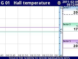
127 Fig Sample of Group parameters settings - all Slot set to Logical channel Fig Sample of Group parameters settings - Slots set to Logical channel and set to empty 127


128 Fig Sample of Group parameters settings - Slots set to Logical channel and set to disabled Groups - Logging options Logging options are available only in the device having a license to log the data (for more information about the logging license is in Chapter 7.4. DEVICE INFORMATION, LICENSE AND FIRMWARE UPDATE). To log the data from the Logical Channel should be: Logical channel attached to Group using the Channels parameter block, enable the data logging by setting the options in block of parameters -> Logging options, after exiting the menu accept the changes by writing configuration, received logging data files can be sent to flash drive (form more information about files management see Chapter 7.3. FILES MANAGEMENT) Each Group has its own data logging options and the MultiCon can log the 10 independent Groups of Logical channels at the same time. Logging of the data in the device is hardware limited, so the producer recommends to limit the logging to less than 200 samples per second (e.g. at the maximum sampling frequency of 0.1 sec. user should not log more than 20 Logical channels at one time). Failure to comply with these restrictions may cause the device to slow down. Logging options parameter block has the following parameters: Mode - this mode has options: disabled - logging of selection Group is disabled, always - logging is continuous in time, from logical channel - this option activate new parameter - Triggering source which enabled logging the data when the value of Triggering source > 0, Triggering source - this parameter is visible for Mode=from log.channel, when value of this source > 0 than the data logging is enabled, Description - user can set a description of a data logging file by pressing the button 128
129 next to the Description label and then setting any text, (in Fig are shown examples of descriptions of any logging files), Base period and Base unit - this parameters set duration of the sample of data logging, these parameters have the following options: unit: second -> duration form 0.1 to 3600 sec., unit: minute -> duration form 0.1 to 1440 minute, unit: hour -> duration form 0.1 to 24 hour, Alternative mode - this mode allows the user to log data in special situation where a deeper analysis is required (for example in critical state of object),this parameter has the following options: disabled - alternative logging of selection Group is disabled, from logical channel - this option activate new parameter - Triggering source which enabled logging the data when the value of Triggering source > 0, Alternative source - this parameter is visible for Mode=from log.channel, when value of this source > 0 than the data logging for alternative mode is enabled, Alternative period and Alternative unit - this parameters set duration of the sample of data logging for alternative mode, these parameters have options: unit: second -> duration form 0.1 to 3600 sec., unit: minute -> duration form 0.1 to 1440 minute, unit: hour -> duration form 0.1 to 24 hour, Fig The Logging options block parameters i For any changes to the settings of the configuration of logging Group (e.g. a change in the logging parameters, changing parameters of Display options parameter block or change parameters of Logical channel included in logging Group) creates a new logging file. If user shuts down the device or changes other parameters independent of logging Group new logging file is not created Groups - Examples of visualisations of groups Example : Single channel - one big needle. If user needs to visualise single hardware input value it is necessary to define one Logical channel and one Group with one active channel. Moreover to show incoming data as a single big needle (Fig. 7.96) it is necessary to disable all unused visualisation slots in a 129
![Group. Of course other presentation modes are also available, to switch between modes use [MODE] buttons in Navigation bar. Fig. 7.96. Single big needle example Example 7.13.](/docs-images/93/112545168/images/130-0.jpg "3.2: Three channels view - one bigger, two smaller If some measured parameters are more important then other there are some ways to emphasis them.")

130 Group. Of course other presentation modes are also available, to switch between modes use [MODE] buttons in Navigation bar. Fig Single big needle example Example : Three channels view - one bigger, two smaller If some measured parameters are more important then other there are some ways to emphasis them. Lets assume then the pressure in some chamber is key parameter, and temperature and humidity are less important. The process of MultiCon CMC-99/141 configuration starts with definition of 3 Logical Channels one for every parameter. Their sources should be in this example a Hardware inputs with appropriate scaling and definition of units. Defined channels should be collected into one group. The key matter for desired presentation is configuration of slots sources in the group. Example view of assumed problem is showed in Fig To get such result slots of the group should be set as follow: Slot 1: Log. ch. 7 Pressure ; Slot 2: disabled; Slot 3: disabled; Slot 4: Log. ch. 9 Temperature ; Slot 5: Log. ch. 1 Humidity ; Slot 6: disabled. Fig Example of three channels presentation with emphasis of Pressure 130
131 Switching between modes it is noticeable that position of particular channels can slightly vary. It is caused by aspect of different modes their position is selected in that way to obtain elements of particular data panels as big as possible MODBUS General settings Logical channels Built-in inputs Built-in outputs External outputs Profiles/timers Controllers Groups MENU Device configuration Modbus Network settings Access options The basic version of MultiCon has one RS-485 port built-in. The ability of communication can be increased by installing a communication module into slot D of the device (Fig. 7.98). This module offers 2 additional serial ports (one RS-485, and one RS-485/RS-232), which allows the creation of an advanced Multi-Modbus system. In the current software version, a MODBUS RTU protocol only is available and every port can be switch to Slave or Master mode. Port MB2 Power supply (depending on version) RS RS-485 Port MB3 1 2 RS-485 Slot D- ACM module RS (2) B- (2) B- A+ (2) RS (3) A+ SLAVE device B- (3) A+ (3) BA+ SLAVE device RS (3) RxD (3) TxD (3) CTS (3) RTS (3) USB device Port MB1 SLAVE device BA USB host +24V DC ±5% (Imax. = 200mA) BA+ digital input 0/15..24V DC RJ-45 ETH RS-485 insulated Fig Serial communication ports available in the device 131
132 Modbus - general settings Window with basic parameters of communication interfaces is shown in Fig Fig Configuration parameters for SLAVE mode Arrows placed in the upper right corner of the screen allow switching between available serial ports. The middle button can be used for direct selection of a specific communication port from the list. Parameter common for all Modbus protocol modes is: Mode - which has option: disabled, the selected Modbus port is inactive, SLAVE - this device is SLAVE device, see Chapter Modbus - SLAVE mode, MASTER, this device is MASTER device and manages the Slave devices, see Chapter Modbus - MASTER mode Modbus - SLAVE mode Parameters of Modbus protocol for SLAVE mode are: Mode = SLAVE, Baud rate - this parameter allows to the selection a baud rate RS-485 interface, available option: 1200, 2400, 4800, 9600, 19200, 38400, 57600, bit./sec., Format - data format of RS-485 interface, available options: Format Number of data bits 132 parity control Number of stop bits 8N1 8 N - none 1 8N2 8 N - none 2 8E1 8 E - even 1 8E2 8 E - even 2
133 Format Number of data bits parity control Number of stop bits 8O1 8 O - odd 1 8O2 8 O - odd 2 Address - SLAVE device address, available address range: 1 255, In this mode the device parameters and measurement result are available via RS-485 interface, as HOLDING-type registers of Modbus RTU protocol. The registers (or groups of the registers) can be read by 03h function, and written by 06h (single registers) or 10h (group of the registers) accordingly to Modbus RTU specification. See Chapter Modbus SLAVE - The Modbus protocol handling for detailed description of MODBUS protocol handling in MultiCon device Modbus SLAVE - The Modbus protocol handling Transmission parameters: 1 start bit, 8 data bits, 1 stop bit, no parity control Baud rate: selectable from: 1200 to bits/second Transmission protocol: MODBUS RTU compatible Modbus SLAVE - List of registers The device parameters and measurement result are available via RS-485 interface, as HOLDING-type registers of Modbus RTU protocol. The registers (or groups of the registers) can be read by 03h function, and written by 06h (single registers) or 10h (group of the registers) accordingly to Modbus RTU specification. Register Write Range 20h No h No 2050h, 2060h Register description Address of device Device identification code 2050h - device in big housing (5.7 display), 2060h - device in small housing (3.5 display). Measurements results (floating point format) 1 200h No 201h 0 0FFFFh Measurement result for logical channel 1 (high word) 0 0FFFFh Measurement result for logical channel 1 (low word) Status for logical channel 1: 0h - data valid, 1h - data not ready, 20h - software error, 40h - bottom border of the software measurement range is exceeded, 80h - top border of the software measurement range is exceeded, 2000h - hardware error, 4000h - bottom border of the hardware measurement range is exceeded, 8000h - top border of the hardware measurement range is exceeded, FFFFh - data not available (e.g. logical channel not configured) 202h No 0 0FFFFh 203h No 0 6 Register from 204h to 2F0h Decimal point for logical channel 1 Measurement results, status and decimal point for Logical Channels
134 Register Write Range Register description Measurements results (integer format) 1 400h No 0 0FFFFh Measurement result for logical channel 1 (high word, not considering the decimal point) 401h No 0 0FFFFh Measurement result for logical channel 1 (low word) Status for logical channel 1: 0h - data valid, 1h - data not ready, 20h - software error, 40h - bottom border of the software measurement range is exceeded, 80h - top border of the software measurement range is exceeded, 2000h - hardware error, 4000h - bottom border of the hardware measurement range is exceeded, 8000h - top border of the hardware measurement range is exceeded, FFFFh - data not available (e.g. logical channel not configured) 402h No 0 0FFFFh 403h No 0 6 Register from 404h to 4F0h Decimal point for logical channel 1 Measurement results, status and decimal point for Logical Channels 2 60 IEEE 754 standard, Float point format represents data as precision as possible. Integer 32 represents value with constant precision,selected by decimal point position. When decimal is set for example 0.0 then Int32 format represents integer part of the value contained in float registers and multiplied by 10 (e.g.: float is , D.P. = 0.0, then Integer = 12). Similarly when decimal pint is then integer represents integer part of the value contained in float registers and multiplied by 1000 (e.g.: float is , D.P = 0.0, then Integer = 1234) Modbus SLAVE- Transmission errors handling If during reading or writing one of registries an error occurs then the unit shall return the frame containing the error code (according to the Modbus protocol). Error codes should be interpreted as follows: 01h - illegal function (only functions 03h, 06h and 10h are available), 02h - illegal register address 03h - illegal data value Modbus SLAVE- Example of query/answer frames The examples concern a unit with address 1. All values are given in the hexadecimal system. Designations: ADDR Address of the device in the system FUNC Function number REG H,L Higher and lower part of registry number, to which the command refers to COUNT H,L Higher and lower part of registry counter number, to which the command refers to, starting with the register, which is defined by REG (max. 32) BYTE C Number of higher bytes in the frame DATA H,L Higher and lower part of data word CRC L,H Higher and lower part of CRC sum 134
135 1. Read of ID code ADDR FUNC REG H,L ADDR FUNC BYTE C COUNT H,L CRC L,H 01 D4 00 The answer: DATA H,L 20 CRC L,H 60 A1 AC DATA H,L - identification code (2060h) 4. Read of the registers 401h, 402h and 403h in one message (example of reading a number of registries in one frame): ADDR FUNC REG H,L COUNT H,L CRC L,H 55 3B COUNT L - the count of being read registers (max. 32) The answer: ADDR 01 FUNC BYTE C 03 DATA H1, L1 DATA H2, L2 DATA H3, L3 i 06 DATA H1,L1 00 0A DATA H2,L DATA H3,L CRC L,H 18 B4-401h registry (10 high word of value for channel 1, no decimal point), - 402h registry (2 low word of value for channel 1, no decimal point), - 403h registry (0 status for channel 1). There is no full implementation of the Modbus Protocol in the device. The functions presented above are the only available Modbus - MASTER mode The parameters of a Modbus protocol for MASTER mode are: Mode = MASTER, Baud rate - this parameter allows the user to select baud rate RS-485 interface, available option: 1200, 2400, 4800, 9600, 19200, 38400, 57600, bit./sec., Request timeout - is the amount of time (any value between 0.01 to 3 sec.) the master device waits for a response from the Slave device after sending a query, Request retrials - this is the number of times (integer value between 1 to 5) a Master device tries to send a message, Slave device - this Button enters submenu allows to define the list of Slave devices 135
136 connected to the current serial port of MultiCon and configure registers for read and/or write. See below for more informations about this menu. Reg. num. displaying - this parameter allows to change mode of displaying the Regsister adresses for Logical channel and External output menu. Two formats are available: hexadecimal - the registers are displayed in hexadecimal format. To indicate that data has a hexadecimal format, the letter 'h' is added at the end - for example, 12h (0x12), decimal - the registers are displayed in decimal format (without any marker) e.g. 123 Slave device menu. MultiCon allows to address as many as 255 slave devices on the addresses from 1 to 255. The Idea of SLAVE devices menu is based on defining the devices connected to the MASTER on a specific adresses. To define external data source, first an address must be chosen, next further parameters of the SLAVE device (having this address) set. Arrows placed in the upper right corner of the screen allow switching between addresses of SLAVE devices to define or modify the settings of Slave devices in specific address. The middle button allows direct selection of specific address from the list. If the particular address is not used, then a short menu is displayed: Device type which has the following options: not present - means that this address is not used (in other words - there is no SLAVE device with this address connected), defined - after selecting this option an extended list of SLAVE device parameters will appear, see below for details Load device template, this button allows the loading a template with predefined blocks of input and / or output registers. Pressing this button invokes a file selecttion window (Fig 7.100). After sucessful loading of the template an extended list of SLAVE device parameters will appear, see below for details. Templates can be imported into the MultiCon using a File Management menu and also created by the user using Save device template button after fully configuration of a slave device. If the Device type is set to defined or a Template has been loaded, then extended SLAVE device menu is shown. This menu as following fields: Device type = defined, Device name - to create or change the name of a SLAVE device, press the button next to the Device name label and enter the name using displayed editor, Device templates parameter block see Chapter for extended descriptopn, Device channels parameter block - see Chapter for extended descriptopn, Register blocks parameter block - see Chapter for extended descriptopn, Modbus MASTER - Device templates parameter block This block is composed of 2 buttons: Load device template - function is the same as presented in short menu description Save device template - allows tthe user to save a configured SLAVE device as 136
137 a template for further usage. Saved template can be used for: fast copying/moving of the SLAVE device to another address (use Load device template) easy creation of similar SLAVE devices by loading the tempalte in another address and modification of parameters. easy moving exchange of templates between different MultiCon devices (using File Management menu). An example of Modbus template selection window is shown in Fig Below this figure additional icons are described. Fig Template selection window This button invokes software keyboard window allowing write or search the template name. This button allows the user to delete selected template. Navigation keys allows the user to select appropriate template Modbus MASTER- Device channels parameter block This block includes following buttons: Input list this button runs submenu related to the Inputs of SLAVE device Output list this button runs submenu related to the Outputs of SLAVE device Both these submenus has basic icons presented below. Their functions are as follow: This button allows the user to add a new Input/Output to Input list / Output list, This button allows the user to delete the Input/Output from Input list / Output list 137
138 Arrows placed in the upper right corner of the screen allows user to switch between Inputs/Outputs. The middle button moves directly to specific Input/Output channel selected from the list. Input List sub-menu. When at least one Input Channel is added to the Input list, then an Input channel menu is displayed. This menu consist of following fields: Channel value parameters block composed of buttons: Value register - by pressing the button next to the Value register label, the user goes to the menu where the details of the Modbus register serving data of input being can be set, Decimal point - pressing of the button next to Decimal point label a list of available decimal point positions appears, in a last place there is an option: * exp (-point register). Selecting this value a new field (Decimal point register) will appear in the Channel value block. Decimal point register, this parameter appears when the Decimal point parameter is set to * exp (-point register) option and allows the user to select the SLAVE device's register containing information about decimal point position. Using this parameter, the Channel value is being displayed according to formula: data of Value register 10 Decimal Channel status '-HI-' parameter block, gathers parameters defined when a status -HI- should be displayed (returned) in a place of numerical value of Input Channel. In this block a folowing parameters can be displayed -HI- state - it has 3 options: never do not display status '-HI-'; for this option, other parameters of Channel status '-HI-' block are invisible, if register = value - state '-HI-' is returned if data read from '-HI- register' equals to '-HI- value' parameter, if register value - state '-HI-' is returned if data read from '-HI- register' differs from '-HI- value' parameter, 138 point register -HI- register - allows the user to select a status register to be read (see above) -HI- value - allow the user to define the value being returned corresponding to status -HI- (see above) Channel status '-LO-' parameter block, gathers parameters defining status -LO-: -LO- state - it has 3 options: never do not display status '-LO-'; For this option, other parameters of Channel status '-LO-' block are invisible, if register = value - state '-LO-' is returned if data read from '-LO- register' equals to '-LO- value' parameter, if register value - state '-LO-' is returned if data read from '-LO- register' differs from '-LO- value' parameter,
139 Channel status '-WAIT-' parameter block, gathers parameters defined when a status -WAIT-WAIT- state - it has 3 options: never do not display status '-WAIT-'; For this option, other parameters of Channel status '-WAIT-' block are invisible, if register = value - state '-WAIT-' is returned if data read from '-WAITregister' equals to '-WAIT- value' parameter, if register value - state '-WAIT-' is returned if data read from '-WAITregister' differs from '-WAIT- value' parameter, -WAIT- register - allows the user to select a status register to be read (see above) -WAIT- value - allows the user to define value returned corresponding to status -WAIT- (see above) Channel status '-ERR-' parameter block, gathers parameters defining when a status -ERR-ERR- state, - it has 3 options: never do not display status '-ERR-'; For this option, other parameters of Channel status '-ERR-' block are invisible, if register = value - state '-ERR-' is returned if data read from '-ERRregister' equals to '-ERR- value' parameter, if register value - state '-ERR-' is returned if data read from '-ERRregister' differs from '-ERR- value' parameter, i -LO- register - allows to select a status register to be read (see above) -LO- value - allow to define value returned corresponding to status -LO- (see above) -ERR- register - allows the user to select a status register to be read (see above) -ERR- value - allows the user to define value returned corresponding to status -ERR- (see above) When a Logical channel is configured to Modbus mode then while reading the registers from SLAVE device if connection to the SLAVE device is lost, the device returns an error and displays the state -ERR-. Output list sub-menu This submenu allows the user to edit the output channels registers to be writen. When at least one Output Channel is added to the list, then an Output channel menu is displayed. The parameters of the Output channels are: Output active, no - the output channel is defined but invisible in the External output menu, yes - the output channel is defined and visible in the External output menu Channel value parameter block gathers following fields: 139
140 Control type as a relay - the output has two state, low state: value '0' and high state: maximal value (for 16-bit format is the value 65535), as a linear output - can take any value depending of the settings in Output register and settings the parameters in the External outputs menu, Output register sub-menu - by pressing the button next to the Output register label user goes to the menu where user can set details of the Modbus register to be written. The submenu of registry settings in the Modbus protocol has the following fields: Register type, this parameter is only for the register settings in the Input list menu (for the Output list menu the registers are HOLDING type), a user can select two types: HOLDING - holding registers of SLAVE device compatible with Modbus protocol INPUT - input registers of SLAVE device compatible with Modbus protocol Register number - any value from 0 to Data format, we can select one of these options: 16 bits, signed - integer value, the most significant bit is the sign bit, 16-bits, unsigned - integer value without information about the sign, 32 bits, signed, integer value, the most significant bit is the sign bit, 32-bits, unsigned - integer value withoput information about the sign, 32 bits, float, floating point IEEE 754 format, 16-bits, BCD, unsigned BCD valuet, write two digits in each byte, 32-bits, BCD, unsigned BCD value, write two digits in each byte, 32 bit reading, this parameter is only for 32-bit format, user can select one of these options: two 16-bit registers, one 32-bit register Ordering - this parameter is only for 32-bit formats, the letters ABCD means: A - most significant byte of high words (word = 2 bytes), B least significant byte of the high words, C - most significant byte of low words, D - least significant byte of the low words ABCD (standard) CDAB, DCBA, BADC,
141 Data shift - values can be bit moved to the right any integer value in the range: for 16-bit format from 0 to 15, for 32-bit format from 0 to 31, shift not exist for float format, Data mask, the device allows the user to use the masking of data on individual bits, mask 0xFFFF for 16-bit format is means that the entire value of register is visible, while the 0x0 mask (no mask) means that the value is zero, Modbus MASTER- Register blocks parameter block The device has the ability to read data from the SLAVE devices using multi register queries. By default this feature is configured automaticaly, but can be switched to manual mode. Regsiter blocks group has following fields: Blocks config. mode automatic - the device automatically creates a blocks of registers to be read using the list defined in Device channels sub-menu. Then the Block list is informal only and cannot be edited. manual - user must create a list of registers blocks using Block list parameter Maximum block size - occurs only for the Blocks configuration mode = automatic. This parameter allows user to limit number of data registers to be read at once. It can be very useful when SLAVE devices has a limitation of max number of registers read in a single frame. Block list (invokes informal screen in automatic mode and a sub-menu in manual mode), Block list Sub-menu This button appears only for manual configuration mode and allows the user to add a new block of registers to list of register blocks. This button appears only for manual configuration mode and allows the user to remove the block of registers from the list of register blocks. Arrows placed in the upper right corner of the screen allow switching between register blocks. Middle button allows direct selection of a specific register block. To the Block list parameters are: Block type - defines the function used for data reading/writing, can be set to: read Holding register - register or group of registers read by 03h function, read INPUT register - register or groups of of registers read by the 04h function, write HOLDING register - preset single register by the 06h function and 141
142 i preset multiple registers by the 10h function, Register size - defines data size, can be set to: 16-bit registers - data is read/preset as 16 bit registers; this value can be also used for 32-bit registers reading/preseting. In a such case data is composed as two 16-bit registers and params: First register & Last register must select a minimum of 2 registers (e. g. First register: 3h, Last register: 4h). The important parameter is then also Ordering - see the Chapter ) 32-bit registers - for 32-bit registers reading/preseting only, data is read as one 32-bit register. First register - value indicating the number of the first register of the block, Last register - value indicating the number of the last register of the block, for single block with one 16-bit register the parameter First register and Last register must be the same number register, Manual mode configuration of registers blocks introduces a freedom when setting Block list parameters. Take care to set Block list parameters according to Input list and Output list in Device channels parameter block of the device (see above in this Chapter). If user creates a block of registers to read / preset in which there were not registers appearing on the Input list and Output list in the Device channels parameter this device in the case of: - read - the read whole register block and registers undefined in Input list menu will not be visible in the Logical channel in Modbus mode which cannot be read either a data from this registers and to use this registers to control and regulating process, - preset - will send the frame to preset the entire block of registers and registers which not defined in the Output list will not appear on the External output menu Warning! in this case to Slave devices will be sent to a random value of these registers, uncontrolled by the user, Modbus - Register settings The submenu of registry settings in the Modbus protocol has the following fields: Register type, this parameter is only for the register settings in the Input list menu (for the Output list menu the registers are HOLDING type), a user can select two types: HOLDING - holding registers of SLAVE device compatible with Modbus protocol INPUT - input registers of SLAVE device compatible with Modbus protocol Register number - any value from 0 to Data format, we can select one of these options: 16 bits, signed - integer value, the most significant bit is the sign bit, 16-bits, unsigned - integer value without information about the sign,
143 32 bits, signed, integer value, the most significant bit is the sign bit, 32-bits, unsigned - integer value withoput information about the sign, 32 bits, float, floating point IEEE 754 format, 16-bits, BCD, unsigned BCD valuet, write two digits in each byte, 32-bits, BCD, unsigned BCD value, write two digits in each byte, 32 bit reading, this parameter is only for 32-bit format, user can select one of these options: two 16-bit registers, one 32-bit register Ordering - this parameter is only for 32-bit formats, the letters ABCD means: A - most significant byte of high words (word = 2 bytes), B least significant byte of the high words, C - most significant byte of low words, D - least significant byte of the low words ABCD (standard) CDAB, DCBA, BADC, Data shift - values can be bit moved to the right any integer value in the range: for 16-bit format from 0 to 15, for 32-bit format from 0 to 31, shift not exist for float format, Data mask, the device allows the user to use the masking of data on individual bits, mask 0xFFFF for 16-bit format is means that the entire value of register is visible, while the 0x0 mask (no mask) means that the value is zero, Modbus - Example of Modbus protocol configuration in the device Example : Input configuration of Modbus protocol in MASTER mode Task: This example shows how to configure the Input channel to read the registers of SLAVE devices (eg temperature converters). Read the Register 1 that returns the temperature, Register 3 is a decimal point register and Register 2 is a status register. Devices: Slave device 1 and Slave devices 2 are set to address 1 and 8, respectively and have baud rate: 9600 bit/sec. MultiCon as Master has settings as: Request timeout: 0,2 sec. and Request retrials: 3. For Modbus configuration setting for two same devices may be helpful Modbus template that will be created in this example. Solution: First configure the device then connect the SLAVE device to the device (in accordance with 143
144 Fig ). Slave device 1 Device name:temp. converter Modbus settings: Baud rate: 9600 bit./sek. Slave address: 1 BA+ 1 Registers: Register: 1h Register: 2h Register: 3h 2 Power supply (depending on version) Master Device Slave device 2 Device name:temp. converter Modbus settings: Baud rate: 9600 bit./sek. Slave address: 8 Registers: Register: 1h Register: 2h Register: 3h USB device V DC ±5% (Im ax. = 200m A) BA+ digital input 0/15..24V DC Port MB1 RS-485 insulated Fig Connection diagram for the Modbus port MB1 Description of the register of SLAVE device shown below in the table Register Range Register description 01h The temperature measured with a resolution given to 2 decimal places (in the U2 code, excluding decimal point, for example, the value of 3523 means the temperature of C) 02h 00h, 10h, 20h,40h, 80h 03h 0 2 Status of the temperature, contains the error code, which must be interpreted as follows: 00h - measuring correctly 10h - flooding the interior of the sensor 20h - damage temperature sensor 40h - measured temperature is lower -40 C 80h - measured temperature is upper 85 C Specify the decimal point as a result, the value of 2 means that a point precedes the last 2 digits, the value of 0 means no decimal point To read the values sent by RS-485 interface the user needs: To be able to read the value sent by RS-485 include: touching the screen and press the Meningu button, then press the Device configuration button and entering the Modbus menu, using the arrows in the upper right corner to select the communication port, such as 1 (Port number: 1, MB1 in accordance with Fig ) Select Mode = Master, because comunication with SLAVE devices to read the registers set the baud rate, the same as the slave devices bit. / sec., set the Request timeout: 0.2 sec., 144
145 set the Request retials: 3, press the SLAVE devices button to configure the SLAVE devices: in the upper right corner using the arrow keys to select the SLAVE device address, in the case of this example the Modbus address: 1, select defined in the Device type parameter, enter the Device name: Temperature converter, skip Device templates parameter block because we have not defined any templates, in the Device channels parameter block press the Input list button to define the register to read, if the Input list is empty, press the sign '+' to add input channel (if the list has defined the input channels use the arrows in the upper right corner to select the input channels) in the Value register parameter set: Register type: HOLDING - using 03h function to read the holding registers as specified by the Modbus RTU, Register number: 1h - the number of the read register Data format: 16 bits, signed - the choice of format depends on SLAVE device register format, Data shift: 0, because we do not want to move data read from Slave device, Data mask: 0xFFFF, which reads the whole value of register, exit the Value register parameter menu, in the Decimal point parameter select option: * exp (-point register) causes that will be appear a new parameter to appear - Decimal point register that casues an automatic change of decimal point, depending on value of Decimal point register, in the Decimal point register parameter set: Register type: HOLDING, Register number: 3h, Data format: 16 bits, unsigned, Data shift: 0, Data mask: 0x0003, because the interest to us only the firsis t 2 bits changing register value, the value of which determines the decimal point, exit after the settings this menu, in the Channel status '-HI-' parameter block select option: if register = value in the -HI- state parameter, which will cause two new parameters: -HI- register and -HI- value, which were the cause, in the case of equality of values of these parameters the value in place of Value register will be located state -HI-, in the -HI- register parameter set: Register type: HOLDING, Register number: 2h, Data format: 16 bits, unsigned, Data shift: 0, Data mask: 0x0080, because we are only interested in changing the value of 8-bit, which in the case of value: '1' indicates over-range temperature converter used in this example, after selecting the settings of this menu, exit the -HI- register parameter, in the -HI- value parameter for the signal -HI- set the value of 0x0080, in the Channel status '-LO-' parameter block select option: if register = value 145
146 146 in the -HI- state parameter, which will cause two new parameters: -HI- register and -LO- value, which were the cause, in the case of equality of values of these parameters the value in place of Value register will be located state -LO-, in the -LO- register parameter set: Register type: HOLDING, Register number: 2h, Data format: 16 bits, unsigned, Data shift: 0, Data mask: 0x0040, because we are only interested in changing the value of 7-bit, which in the case of value: '1' indicates over-range temperature converter used in this example, after selecting the settings of this menu, exit the -LO- register parameter, in the -LO- value parameter for the signal -LO- set the value of 0x0040, skip the Channel status '-WAIT-' parameter block leaving the -WAIT- state parameter to the option: never, in the Channel status '-ERR-' parameter block select option: if register value in the -ERR- state parameter, which will cause t two new parameters: -ERRregister and -ERR- value, which were the cause, in the case of no equality of values of these parameters the value in place of Value register will be located state -ERR-, in the -ERR- register parameter set: Register type: HOLDING, Register number: 2h, Data format: 16 bits, unsigned, Data shift: 0, Data mask: 0x00C0, because we are only interested in changing all the values except the 7, 8 bits, which in the case of the value no being equal to '0' indicates error code, after selecting the settings of this menu, exit the -ERR- register parameter, in the -ERR- value parameter for the signal -ERR- set the value of 0x0000, exit from the Input list menu, don't enter into the Output list menu, because we only read the register in accordance with the contents of the exercise, move to the Register blocks parameter block, set the Blocks configuration mode parameter to automatic mode, The Maximum block size parameter set to eg 5, because the slave device selected in this example allows reading frame (using the Modbus function 03h) with up to 5 registers, this device automatically creates a block of registers (creates one block of 3 registers), the structure of block can see by pressing the Block list button, after creating the configuration of the Modbus register to read registers from SLAVE device can be saved by the Modbus settings by saving a Modbus template, move to the parameter block device templates and press the button Save Template move to the Device templates parameter block and press the button Save device template, in the Save device template menu, enter the template name, eg 'Temperature converter' (stored template can be used to configure the device to a different address), by arrows in the upper right corner of the screen, go to the Modbus address: 8, in the Modbus address: 8 - skip Device type parameter, and press the Load
147 device template button and in the template list select the template that has just been saved with the name 'Temperature converter'; in such a fast way to have set all the parameters for the SLAVE device 2 identical to SLAVE device 1, exit from the SLAVE devices menu, Register number displaying set in hexadecimal, Example : Configuration of the Modbus Input in the MASTER mode. In this example we show how to configure the Input channel of SLAVE device, e.g. for TRS04a device with address 3. We read the Register 1, Register 5 is the Decimal point register, Register 2 is the Status register which the value of 80h means that the temperature measurement exceeds the 85ºC. In the first step we enter the Modbus SLAVE device menu. We select by using arrows in upper navigation bar the appropriate address of SLAVE device (address 3). Device type parameter we set to defined or we can use predefined template with available settings for TRS-04a device by pressing Load device templates button. In this example we use first case when the SLAVE device is defined by user. Next we go to the block parameters Device channel and pressing the Input list button. In the Input list menu to open new input channel we press a button '+'. When we want to delete a channel press the button '-'. After adding the new input channel need to set appropriate parameters. Parameter Value register we set like in the Fig Next we exit from Value register menu. Fig Value register parameters In the Decimal point parameter we select option: value multiplied by the Decimal point register (*exp(-point register)) and in the Decimal point register parameter we write values as for the Value register of Fig with the change to the register number 5. Next point we set block parameters for Channel status -Hi-. The settings of block parameters shown in the Fig The remaining values are left inactive (value: never). 147

148 Fig Sample setting for the block parameters: Channel status -HiAfter configuration the Input channels of the device we set parameters Register blocks. However we exit Input list menu and move window over parameters called Register blocks and set them as follow Block configuration mode we set to automatic, Max. block size we set to 3. MultiCon CMC-99/141 device automatically select the optimal list of blocks. After whole configuration exit the menu pressing Save changes. Example : Configuration of the Modbus Output in the MASTER mode. In this example we show how to configure the Output channel of SLAVE device, e.g. for TRS-10a device with address 5. Save data to Register 1, Register 2 set to 0, Register 5 set to 0 (mode: decimal). In the first step we enter the Modbus SLAVE device menu. We select by using arrows in upper navigation bar the appropriate address of SLAVE device (address 5). Device type parameter we set to defined or we can use predefined template with available settings for TRS-10a device by pressing Load device templates button. In this example we use first case when the SLAVE device is defined by user. Next we go to the block parameters Device channel and pressing the Output list button. In the Output list menu to open new output channel we press a button '+'. When we want to delete a channel press the button '-'. After adding the new output channel need to set appropriate parameters. The Output active parameter set to active - when you set no then the output will be defined but invisible after exit from Modbus menu. Control type parameter set to as a linear output. Parameter Output register we set like in the Fig Next we exit from Output register menu. 148
User manual CONTROLLER/DATA RECORDER. MultiCon CMC-99/141
 Assisting the automation industry since 1986 User manual CONTROLLER/DATA RECORDER MultiCon CMC-99/141 Firmware: v.5.02.3 or higher Read the user's manual carefully before starting to use the unit or software.
USER MANUAL for. MultiCon
 SIMEX USER MANUAL for MultiCon device type: CMC-99 X/X/X-1-X-0XX firmware version: 1.00 or higher Read the user's manual carefully before starting to use the unit or software. Producer reserves the right
KBL Instruction Manual
 Electronic Multi-Channel Datalogger KBL Instruction Manual KOBOLD Instruments UK Ltd 8/9 Brunts Business Centre, Samuel Brunts Way, Mansfield, Nottingham, NG18 2AH Phone: 01623 427701 Email: info.uk@kobold.com
USER MANUAL for. data logger with 0/4 20 ma inputs Loggy Soft v or higher S-Toolkit v or higher
 USER MANUAL for data logger with 0/4 20 ma inputs Loggy Soft v. 1.5.5 or higher S-Toolkit v. 1.7.0 or higher device type: PAR-99X - X100 firmware version: 2.10 b972 or higher Read the user's manual carefully
Firmware version or higher
 průmyslová elektronika INSTRUCTION MANUAL Multifunctional graphical unit MGU 800 Firmware version 2.27.0 or higher Read.carefully.the.instructions.published.in.this.manual.before.the.fi.rst.use.of.the.level.meters..Keep.the.
User manual DATA RECORDER SRD-99
 Assisting the automation industry since 1986 User manual DATA RECORDER SRD-99 Firmware: v.3.34 b1 or higher Loggy Soft: v.1.9.0 or higher S-Toolkit: v.2.0.23 or higher Read the user's manual carefully
Operating manual. Multichannel Process Display LCD with Datalogger U / I Input CIT 650
 Operating manual Multichannel Process Display LCD with Datalogger U / I Input CIT 650 notes: Please read this operating manual carefully before installing and starting up the programming kit. This operating
User manual DATA RECORDER SRD-N16
 Assisting the automation industry since 1986 User manual DATA RECORDER SRD-N16 Firmware: v.3.34 b1 or higher Loggy Soft: v.1.9.0 or higher S-Toolkit: v.2.0.23 or higher Read the user's manual carefully
USER MANUAL for. Loggy Soft v or higher. S-Toolkit v or higher SRD-99 - X X
 SIMEX USER MANUAL for data logger with Pt 100/500/1000 inputs Loggy Soft v. 1.5.8 or higher S-Toolkit v. 2.0.0 or higher device type: SRD-99 - X328-1 - X firmware version: 3.00 b980 or higher Read the
User manual DATA RECORDER SRD-N16
 Assisting the automation industry since 1986 User manual DATA RECORDER SRD-N16 Firmware: v.3.17 b1 or higher Loggy Soft: v.1.8.0 or higher S-Toolkit: v.2.0.15 or higher Read the user's manual carefully
Operating manual. Multichannel Process Display LCD. U/I Input CIT 600
 Operating manual Multichannel Process Display LCD U/I Input notes: Please read this operating manual carefully before installing and starting up the programming kit. This operating manual must be kept
 www.omniinstruments.co.uk Introduction The MultiCon series includes advanced controllers and recorders with great potential closed in small casings. MultiCon CMC has been specifically designed for advanced
MULTICHANNEL DATA RECORDERS
 MULTICHANNEL DATA RECORDERS Introduction ma + V / mv RTD + - universal inputs + - TC universal inputs: RTD + TC or U + I (SRD-99) fixed inputs: RTD, TC, U, I (SRD-N16) 2 relay outputs memory up to 3 000
CMC-99 (RS ) multichannel CONTROLLERS data recorders
 multichannel CONTROLLERS data recorders") CMC-99 (RS 825-1382) multichannel CONTROLLERS data recorders The MultiCon series includes advanced controllers and recorders with great potential closed in small casings. MultiCon CMC has been specifically
CMC-99 (RS 825-1382) multichannel CONTROLLERS data recorders The MultiCon series includes advanced controllers and recorders with great potential closed in small casings. MultiCon CMC has been specifically
HITACHI. EH-150 series PLC EH-RTD8 Resistance Temperature Detective input module Instruction manual. Safety precautions
 HITACHI EH-150 series PLC Resistance Temperature Detective input module Instruction manual Thank you for purchasing a Hitachi Programmable Logic Controller. To operate it safely, please read this instruction
MULTICHANNEL DATA RECORDERS
 MULTICHANNEL DATA RECORDERS Introduction ma + V / mv RTD + - universal inputs + - TC universal inputs: RTD + TC or U + I (SRD-99) fixed inputs: RTD, TC, U, I (SRD-N16) 2 relay outputs memory up to 3 000
TOP - 1. Instruction Manual. Version 1.0 Produced in Jan. 2004
 Version 1.0 Produced in Jan. 2004 Instruction Manual LCD monitor IV-08MP Thank you for purchasing the SHARP IV-08MP LCD monitor. Read this introductory instruction manual carefully to thoroughly familiarize
multichannel CONTROLLERS data recorders
 multichannel CONTROLLERS data recorders Introduction The MultiCon series includes advanced controllers and recorders with great potential closed in small casings. MultiCon CMC has been specifically designed
User manual INDICATOR SWE-94-S
 Assisting the automation industry since 1986 User manual INDICATOR SWE-94-S Firmware: v.1.00 or higher Input type: RS-485 Master / Slave function, low-cost, no keyboard Read the user's manual carefully
User manual COUNTER SLE-73
 Assisting the automation industry since 1986 User manual COUNTER SLE-73 Firmware: v.4.00 or higher Input type: pulse Low-cost counter Read the user's manual carefully before starting to use the unit or
Portable Data LOGGING SYSTEMS. for Professionals
 Portable Data LOGGING SYSTEMS for Professionals Introduction SIMEX is a Polish manufacturer and supplier of industrial automation equipment. The company has been in the market for nearly 0 years and offers
Conductive Level Controller
 Conductive Level Controller 61F-D21T-V1 Ideal for level control for industrial facilities and equipment. Outputs can be set to self-hold at ON or OFF using self-holding circuits. Sensitivity adjustment
EX-RC1 Remote I/O Adapter
 EX-RC1 Remote I/O Adapter The EX-RC1 interfaces between Unitronics Vision OPLCs and remote I/O Expansion Modules distributed throughout your system. The adapter is connected to a PLC via CANbus. Each adapter
Tempco Instruction Manual
 Tempco Instruction Manual 1/16 DIN Solid State Temperature Controller Relay Output Solid State Output For Heating Model Numbers: TEC-901, TEC-902, TEC-905 Temperature controls in this series are designed
Operating instructions. Switching amplifier DN0210 DN / / 2015
 Operating instructions Switching amplifier DN0210 DN0220 UK 80011079 / 00 01 / 2015 Contents 1 Preliminary note...4 1.1 Symbols used...4 1.2 Warning signs used...4 2 Safety instructions...5 2.1 General...5
PanelView Plus/VersaView CE Terminals and Display Modules
 Installation Instructions PanelView Plus/VersaView CE Terminals and Display Modules (Catalog Numbers 2711P-xxxxxx, 6182H-xxxxxx) English Inside: Overview...2 For More Information...2 Modular Components...3
SOLARIMMERSION IV Advanced Installation Manual v1.9
 SOLARIMMERSION IV Advanced Installation Manual v1.9 1 Contents 1. Overview 2. Technical Specifications 3. Installation Mounting Electrical Installation Clamp Installation Wiring Diagrams 4. Installation
CEM M-RS485 INSTRUCTION MANUAL (M014B A)
") Communications interface CEM M-RS485 INSTRUCTION MANUAL (M014B01-03-14A) 2 SAFETY PRECAUTIONS Follow the warnings described in this manual with the symbols shown below. DANGER Warns of a risk, which could
Communications interface CEM M-RS485 INSTRUCTION MANUAL (M014B01-03-14A) 2 SAFETY PRECAUTIONS Follow the warnings described in this manual with the symbols shown below. DANGER Warns of a risk, which could
PRO-1250D CT MID DIN rail three phase four wire energy meter.
 PRO-1250D CT MID DIN rail three phase four wire energy meter. 1.1 Safety instructions 1.2 Foreword 1.3 MID certificate 1.4 Performance criteria 1.5 Specifications 1.6 Basic errors 1.7 Description 1.8 Dimensions
Installation Guide V290 (Color) This guide provides basic information for Unitronics LCD color touchscreen models V C30B and V T40B.
 This guide provides basic information for Unitronics LCD color touchscreen models V C30B and V T40B.") Vision OPLC Installation Guide V290 (Color) This guide provides basic information for Unitronics LCD color touchscreen models V290-19-C30B and V290-19-T40B. General Description Vision OPLCs are programmable
Vision OPLC Installation Guide V290 (Color) This guide provides basic information for Unitronics LCD color touchscreen models V290-19-C30B and V290-19-T40B. General Description Vision OPLCs are programmable
F1000 User's Manual. (Version: V1.01)
") (Version: V1.01) Contents Chapter 1 Overview... 2 Chapter 2 Installation... 3 2.1 Installation guide... 3 2.1.1 Installation position... 3 2.1.2 NEMA4 standard installation... 3 2.1.3 Environment precautions...
(Version: V1.01) Contents Chapter 1 Overview... 2 Chapter 2 Installation... 3 2.1 Installation guide... 3 2.1.1 Installation position... 3 2.1.2 NEMA4 standard installation... 3 2.1.3 Environment precautions...
H Series PLC. ! : Indicates Compulsion. EH-150 Analog input module EH-AXH8M Instruction manual. Safety precautions DANGER CAUTION COMPULSION
 H Series PLC EH-150 Analog input module EH-AXH8M Instruction manual Thank you for purchasing a Hitachi Programmable Logic Controller. To operate it safely, please read this instruction manual and all the
Operating instructions. Speed monitor D / / 2014
 Operating instructions Speed monitor D200 80005257 / 00 05 / 2014 Contents 1 Preliminary note...4 1.1 Symbols used...4 1.2 Warning signs used...4 2 Safety instructions...5 2.1 General...5 2.2 Target group...5
DXTH DUCT SENSOR / SWITCH FOR TEMPERATURE AND HUMIDITY. Mounting and operating instructions
 DUAL DUCT SENSOR / SWITCH FOR TEMPERATURE AND HUMIDITY Mounting and operating instructions Table of contents SAFETY AND PRECAUTIONS 3 PRODUCT DESCRIPTION 4 ARTICLE CODES 4 INTENDED AREA OF USE 4 TECHNICAL
OPLC Installation Guide
 Samba OPLC SM35-J-R20/SM43-J-R20 SM70-J-R20 SM35-J-T20/SM43-J-T20 SM70-J-T20 OPLC Installation Guide 12 Digital Inputs, include 1 HSC/Shaft-encoder Input, 2 Analog inputs (only when the digital inputs
LXEM145 SERIES Lanx Australis single Phase KWh Meter 45Amp. User manual
 LXEM145 SERIES Lanx Australis single Phase KWh Meter 45Amp Single phase two wire DIN rail energy meter (One module) 1.1 Safety instruction 1.2 Foreword 1.3 Performance criteria 1.4 Specifications 1.5 Basic
ESM H 77x35 DIN Size Heating Controller Digital, ON / OFF Temperature Controller
 Internal Buzzer ESM- 3711-H 77x35 DIN Size Heating Controller ESM-3711-H 77 x 35 DIN Size Digital, ON / OFF Temperature Controller - 3 Digits display - PTC Input or, J type Thermocouple Input or, K type
When any of the following symbols appear, read the associated information carefully. Symbol Meaning Description
 Uni-I/O Wide Modules Installation Guide UIS-WCB1 Uni-I/O Wide is a family of Input/Output modules that are compatible with the UniStream control platform. Wide Modules are 1.5 times as wide as Uni-I/O
RXTH DUAL ROOM SENSOR / SWITCH
 DUAL ROOM SENSOR / SWITCH FOR TEMPERATURE AND RELATIVE HUMIDITY Mounting and operating instructions Table of contents SAFETY AND PRECAUTIONS 3 PRODUCT DESCRIPTION 4 ARTICLE CODES 4 INTENDED AREA OF USE
LED W RGBA User Manual
 LED- 245-1W RGBA User Manual Please read the instructions carefully before use CONTENTS 1. Safety Instructions...2 2. Technical Specifications...3 3. How To Set The Unit...4 3.1 Control Panel...4 3.2 Main
STR-3 STANDARD 3-PHASE 230 VAC TRANSFORMER CONTROLLER. Mounting and operating instructions
 STANDARD 3-PHASE 230 VAC TRANSFORMER CONTROLLER Mounting and operating instructions Table of contents SAFETY AND PRECAUTIONS 3 PRODUCT DESCRIPTION 4 ARTICLE CODES 4 INTENDED AREA OF USE 4 TECHNICAL DATA
Operation Manual Series W-500
 Operation Manual Series W-500 Table of Content 1 Safety information... 2 1.1 Place of application of the unit... 2 1.2 Instructions for installation... 3 2 Start-up and adjustment of controller 4 3 General
When any of the following symbols appear, read the associated information carefully. Symbol Meaning Description
 Vision OPLC V350-35-R34/V350-J-R34 Installation Guide The Unitronics V350-35-R34/V350-J-R34 offers the following onboard I/Os: 22 Digital Inputs, configurable via wiring to include 2 Analog and 3 HSC/Shaft-encoder
Vision OPLC V TR6/V350-J-TR6
 Vision OPLC V350-35-TR6/V350-J-TR6 Installation Guide The Unitronics V350-35-TR6/V350-J-TR6 offers the following onboard I/Os: 8 Digital Inputs, configurable via wiring to include 2 Analog (current/voltage)
Professional Entertainment Technology. imove 50SR. Innovation, Quality, Performance 21-
 Innovation, Quality, Performance 21- imove 50SR User Guide Professional Entertainment Technology EC Declaration of Conformity We declare that our products (lighting equipments) comply with the following
MDM 011-Z1 Regen Resistor
 MDM 011-Z1 Regen Resistor Date of creation: 10.04.2017 Version date: 10.04.2017 Article number: 09-402-011-Z1-E Publisher: SIGMATEK GmbH & Co KG A-5112 Lamprechtshausen Tel.: 06274/4321 Fax: 06274/4321-18
Operating Instructions VEGAMET 381
 Operating Instructions VEGAMET 381 in out Contents Contents 1 About this document... 4 1.1 Function... 4 1.2 Target group... 4 1.3 Symbolism used... 4 2 For your safety... 6 2.1 Authorised personnel...
RXTP ROOM TEMPERATURE
 ROOM TEMPERATURE CONTROLLER WITH PI CONTROL Mounting and operating instructions Table of contents SAFETY AND PRECAUTIONS 3 PRODUCT DESCRIPTION 4 ARTICLE CODES 4 INTENDED AREA OF USE 4 TECHNICAL DATA 4
PM Series Power Meter
 PM Series Power Meter Quick Setup Guide - PMC-1000, PMC- 1001, PMM-1000, PMB-1960 Safety Information DANGER! HAZARD OF ELECTRIC SHOCK, EXPLOSION, OR ARC FLASH Follow safe electrical work practices. See
horizontal and vertical bargraph channel display of a group with units and scalabled plus standardized measured values
 Multichannel Process Display TFT with Contacts, Analogue Outputs and Datalogger Functional range standard configuration of max. 60 channels via inputs, outputs, mathematical / logical functions, controller,
POE084824B. PoE 54V/8x0,3A/4x7Ah PoE buffer power supply for up to 8 IP camera. v.1.1 EN* Edition: 7 from
 POE084824B v.1.1 PoE 54V/8x0,3A/4x7Ah PoE buffer power supply for up to 8 IP camera. EN* Edition: 7 from 15.11.2017 Supersedes the edition: 6 from 22.11.2016 GREEN POWER CCTV PoE PSU features: DC 54V uninterruptible
When any of the following symbols appear, read the associated information carefully. Symbol Meaning Description
 Uni-I/O Modules Installation Guide UID-0808R, UID-0808T, UID-1600,UID-0016R, UID-0016T Uni-I/O is a family of Input/Output modules that are compatible with the UniStream control platform. This guide provides
QUICK SETUP GUIDE PMC-1000, PMC-1001, PMM-1000, PMB PM Series Power Meter. Safety Information. Equipment Maintenance and Service.
 PM Series Power Meter QUICK SETUP GUIDE PMC-1000, PMC-1001, PMM-1000, PMB-1960 Safety Information DANGER! HAZARD OF ELECTRIC SHOCK, EXPLOSION, OR ARC FLASH Follow safe electrical work practices. See NFPA
This guide provides basic information for Unitronics Models 230/260/280/290 (Non-color Screens).
.") Vision OPLC Installation Guide Models 230/260/280/290 (Non-color Screens) This guide provides basic information for Unitronics Models 230/260/280/290 (Non-color Screens). General Description Vision OPLCs
Vision OPLC Installation Guide Models 230/260/280/290 (Non-color Screens) This guide provides basic information for Unitronics Models 230/260/280/290 (Non-color Screens). General Description Vision OPLCs
1. Safety Precautions (Read these precautions before use.)
") R P5102S/N/N1 HMI Installation Guide Thank you for purchasing FATEK HMI. Before installing or operating the unit, please read this installation guide carefully to ensure correct use. 1. Safety Precautions
R P5102S/N/N1 HMI Installation Guide Thank you for purchasing FATEK HMI. Before installing or operating the unit, please read this installation guide carefully to ensure correct use. 1. Safety Precautions
TEMPERATURE AND HUMIDITY TRANSDUCER P18 TYPE USER S MANUAL
 TEMPERATURE AND HUMIDITY TRANSDUCER P18 TYPE USER S MANUAL 1 2 CONTENTS 1. APPLICATION... 5 2. BASIC REQUIREMENTS, OPERATIONAL SAFETY... 5 3. INSTALLATION... 5 3.1. Assembly...5 3.2. Electrical Connections...7
PRO1250D CT MID DIN rail three phase four wire energy meter. User manual Version 1.5
 PRO1250D CT MID DIN rail three phase four wire energy meter. User manual Version 1.5 1 Safety instructions...3 2 Foreword...4 3 CE certificates...5 4 MID certificate...7 5 Performance criteria...8 6 Specifications...8
DRT-301 A/D. User manual. Three phase four wire DIN rail energy meter. (Seven modules) 1.1 Safety instruction. 1.2 Foreword. 1.3 Performance criteria
 1.1 Safety instruction. 1.2 Foreword. 1.3 Performance criteria") DRT-301 A/D Three phase four wire DIN rail energy meter (Seven modules) 1.1 Safety instruction 1.2 Foreword 1.3 Performance criteria 1.4 Specifications 1.5 Basic errors 1.6 Structure Diagram 1.7 Dimensions
DRT-301 A/D Three phase four wire DIN rail energy meter (Seven modules) 1.1 Safety instruction 1.2 Foreword 1.3 Performance criteria 1.4 Specifications 1.5 Basic errors 1.6 Structure Diagram 1.7 Dimensions
When any of the following symbols appear, read the associated information carefully. Symbol Meaning Description
 Uni-I/O Wide Modules Installation Guide UID-W1616R, UID-W1616T Uni-I/O Wide is a family of Input/Output modules that are compatible with the UniStream control platform. Wide Modules are 1.5 times as wide
MVS RAIL ELECTRONIC FAN SPEED CONTROLLER. Mounting and operating instructions
 DIN RAIL ELECTRONIC FAN SPEED Mounting and operating instructions Table of contents SAFETY AND PRECAUTIONS 3 PRODUCT DESCRIPTION 4 ARTICLE CODES 4 INTENDED AREA OF USE 4 TECHNICAL DATA 4 STANDARDS 5 WIRING
Druck DPI 620 advanced modular calibrator
 GE Sensing & Inspection Technologies A1.1 DPI 620: Channel 1 (CH1) Druck DPI 620 advanced modular calibrator safety and quick reference guide - K0454 Measure (M) / Source (S) / Power (P) a ±30 V (M) b
FLÄKTGROUP OFFERS A WIDE RANGE OF PER- MANENT MAGNET MOTORS (PM) AND FREQUENCY CONVERTERS FOR PLUG FANS. POWER RANGE IS FROM 0,8 KW TO 15 KW.
 AND FREQUENCY CONVERTERS FOR PLUG FANS. POWER RANGE IS FROM 0,8 KW TO 15 KW.") CENTRIFLOW PUR 3D (A, PLUG B, C, D) FAN GMPM FC101 AND SLIDE IN FREQUENCY ROTOR CASSETTE CONVERTER QUICK GUIDE FLÄKTGROUP OFFERS A WIDE RANGE OF PER- MANENT MAGNET MOTORS (PM) AND FREQUENCY CONVERTERS
CENTRIFLOW PUR 3D (A, PLUG B, C, D) FAN GMPM FC101 AND SLIDE IN FREQUENCY ROTOR CASSETTE CONVERTER QUICK GUIDE FLÄKTGROUP OFFERS A WIDE RANGE OF PER- MANENT MAGNET MOTORS (PM) AND FREQUENCY CONVERTERS
99 Washington Street Melrose, MA Phone Toll Free Visit us at
 99 Washington Street Melrose, MA 02176 Phone 781-665-1400 Toll Free 1-800-517-8431 Visit us at www.testequipmentdepot.com Table of Contents 1. General Safety Requirements... 1 2. Safety Terms and Symbols...
Operating instructions AS-i SmartLine module AC3200 AC /00 06/2016
 Operating instructions AS-i SmartLine module AC3200 AC3201 80237876/00 06/2016 Contents 1 Preliminary note...3 1.1 Symbols used...3 1.2 Warnings used...3 2 Safety instructions...3 2.1 General...3 2.2 Target
Operating Instructions (Translation) 3. Safety Information. 1. Description. 2. Explosion Protection. Supply module Type 17-21BB-170x
 3. Safety Information. 1. Description. 2. Explosion Protection. Supply module Type 17-21BB-170x") 1. Description The supply module was developed specially for direct mounting in hazardous areas in Zone 1 and 21 and is ATEX-certified. The supply module is a permanently installed piece of electrical
1. Description The supply module was developed specially for direct mounting in hazardous areas in Zone 1 and 21 and is ATEX-certified. The supply module is a permanently installed piece of electrical
RS232C/RS485 Data can be easily monitored by LAN
 KS SIGNAL CVERTER (AKS) RSC/RS8 Data can be easily monitored by LAN KS SIGNAL CVERTER FEATURES The connectors are located on the front panel. Easy to connect Easy to operate Can be connected to the LAN
S-14 S-14. Compact Digital Multimeter. Compact Digital Multimeter
 S-14 Compact Digital Multimeter S-14 Compact Digital Multimeter SAFETY INFORMATION The following safety information must be observed to insure maximum personal safety during the operation at this meter
Model P4017 Single Channel USB Oscilloscope. Quick Start Guide
 Model P4017 Single Channel USB Oscilloscope Quick Start Guide General Warranty BNC warrants that the product will be free from defects in materials and workmanship for 3 years from the date of purchase
IO-PT4. Component identification. User safety and equipment protection guidelines. Unitronics Industrial Automation Systems 1
 IO-PT4 I/O Expansion Module 4 PT100 Inputs (-50 to 460 C) The IO-PT4 is an I/O expansion module that can be used in conjunction with specific Unitronics OPLC controllers. The module offers 4 PT100 inputs
The power behind competitiveness. Delta Infrasuite Power Management. Power Distribution Unit. User Manual.
 The power behind competitiveness Delta Infrasuite Power Management Power Distribution Unit User Manual www.deltapowersolutions.com Save This Manual This manual contains important instructions and warnings
OPERATING INSTRUCTION
 OPERATING INSTRUCTION AUTORANGING MULTIMETER MAX Ω F C 10A MAX every 15 min. COM V SAFETY INFORMATION The following safety information must be observed to insure maximum personal safety during the operation
RTT2 ROOM TEMPERATURE SWITCH. Mounting and operating instructions
 Mounting and operating instructions Table of contents SAFETY AND PRECAUTIONS PRODUCT DESCRIPTION ARTICLE CODES INTENDED AREA OF USE TECHNICAL DATA STANDARDS OPERATIONAL DIAGRAMS WIRING AND CONNECTIONS
CPCI-PS24 24V-Power Supply
 24V-Power Supply Hardware Manual to Product I.2301.21 esd electronic system design gmbh Vahrenwalder Str. 207 30165 Hannover Germany http://www.esd.eu Phone: +49 (0) 511 3 72 98-0 Fax: +49 (0) 511 3 72
1 Channel Strobe Controller ORDERCODE 40226
 1 Channel Strobe Controller ORDERCODE 40226 Congratulations! You have bought a great, innovative product from Showtec. The Showtec Strobe Controller brings excitement to any venue. Whether you want simple
AI531 Analog Input Module
 Ordering Data DATA SHEET AI531 Analog Input Module 1 Ordering Data Part No. Description Product Life Cycle Phase *) 1SAP 250 600 R0001 AI531, analog input module, 8 AI, U/I/Pt100, TC, 15 bits + sign, 4-wires
5 B&W Rear View System Camera
 5 B&W Rear View System Camera Instruction Manual MODEL: CA453 www.lorexcctv.com Copyright 2007 LOREX Technology Inc. Thank you for purchasing the Lorex 5 Black & White Rear View System Camera. This system
SDM120 SERIES. SDM120 series User Manual. Single phase two wire DIN rail energy meter (One module)
") SDM120 SERIES Single phase two wire DIN rail energy meter (One module) User manual ------------ 1.1 Safety instruction 1.2 Foreword 1.3 Performance criteria 1.4 Specifications 1.5 Basic errors 1.6 Dimension
SDM120 SERIES Single phase two wire DIN rail energy meter (One module) User manual ------------ 1.1 Safety instruction 1.2 Foreword 1.3 Performance criteria 1.4 Specifications 1.5 Basic errors 1.6 Dimension
DESIGO RX Individual room controllers. for fan-coil systems, chilled ceilings and radiators, with LONMARK-compatible bus communications
 3 834 DESIO RX Individual room controllers for fan-coil systems, chilled ceilings and radiators, with MARK-compatible bus communications RXC20.1 RXC21.1 The RXC20.1 and RXC21.1 controllers are used for
RST ROOM TEMPERATURE TRANSMITTER. Mounting and operating instructions
 Mounting and operating instructions Table of contents SAFETY AND PRECAUTIONS 3 PRODUCT DESCRIPTION 4 ARTICLE CODES 4 INTENDED AREA OF USE 4 TECHNICAL DATA 4 STANDARDS 4 OPERATIONAL DIAGRAM 5 WIRING AND
PRO1250D CT MODBUS MID Three phase four wire energy meter.
 PRO1250D CT MODBUS MID Three phase four wire energy meter. User manual Version 1.11 1 Safety instructions...3 2 Foreword...4 3 MID certificate...5 4 CE certificate...6 5 Performance criteria...8 6 Specifications...8
USER MANUAL for universal counter with batching function SLIK-73. firmware version: 7.03 or higher
 SIMEX USER MANUAL for universal counter with batching function family: type: SLIK-73 firmware version: 7.03 or higher Read the user's manual carefully before starting to use the unit. Producer reserves
ELV12 Series. Instruction Manual
 Instruction Manual TDK-Lambda BEFORE USING POWER SUPPLY UNIT Be sure to read this instruction manual thoroughly before using this product. Pay attention to all warnings and cautions before using the unit.
BCM2 Series Branch Circuit Monitors Quick Setup Guide
 BCM2 Series Branch Circuit Monitors Quick Setup Guide Safety Information DANGER! HAZARD OF ELECTRIC SHOCK, EXPLOSION, OR ARC FLASH Follow safe electrical work practices. See NFPA 70E in the USA, or applicable
EX-RC1 Remote I/O Adapter
 EX-RC1 Remote I/O Adapter The EX-RC1 interfaces between Unitronics Vision OPLCs and remote I/O Expansion Modules distributed throughout your system. The adapter is connected to a PLC via CANbus. Each adapter
TVAC25100 TVAC25110 User manual
 TVAC25100 TVAC25110 User manual Version 11/2010 Original user manual. Keep for future use. 12 Introduction Dear Customer, Thank you for purchasing this product. This product meets the requirements of the
RТTH DUAL ROOM SWITCH
 DUAL ROOM SWITCH FOR TEMPERATURE AND RELATIVE HUMIDITY Mounting and operating instructions Table of contents SAFETY AND PRECAUTIONS PRODUCT DESCRIPTION ARTICLE CODES INTENDED AREA OF USE TECHNICAL DATA
IGLOO IGLOO EASY INSTRUCTION MANUAL
 ENGLISH EASY C695 C698 INSTRUCTION MANUAL PRELIMINARY Congratulations on choosing a Clay Paky product! We thank you for your custom. Please note that this product, as all the others in the rich Clay Paky
mark150s mark150/485s DDC controllers Summary
 mark150s mark150/485s DDC controllers Summary DDC (Direct digital control) controller mark150s and mark150/485s are free programmable process stations with ARM Cortex M4 processor and OS FreeRTOS. They
LBVR1718. Description. Features channel paperless recorder
 LBVR1718 18 - channel paperless recorder Description It is the world first paperless recorder of the same size in highest resolution 640x480 pixels VGA TFT display, infrared detector, maximum 18 channels,
PRO2DM DIN rail single phase two wire energy meter
 PRO2DM DIN rail single phase two wire energy meter User manual Version 1.04 1 Safety instructions...3 2 Foreword...4 3 CE Certificate...5 4 Performance criteria...6 5 Specifications...6 6 Basic errors...6
High Speed Remote I/O Module
 High Speed Remote I/O Module EXF-RC15 The Unitronics EXF-RC15 is a High Speed Remote I/O Module that offers three High Speed Counter inputs and four high speed outputs. Overall, the EXF-RC15 offers 9 digital
SAMURAI SCAN 50 LED-SC50D. User Guide. Innovation, Quality, Performance. Professional Entertainment Technology 19-
 SAMURAI SCAN 50 LED-SC50D Innovation, Quality, Performance User Guide Professional Entertainment Technology 19- EC Declaration of Conformity We declare that our products (lighting equipments) comply with
V TU24 V350-J-TU24
 Vision PLC+HMI V350-35-TU24 V350-J-TU24 Installation Guide 12 Digital Inputs, including 2 Analog, 2 PT100/TC,1 HSC/Shaft-encoder input 12 Transistor Outputs General Description All of the controllers covered
INSTALLATION DKM-409 NETWORK ANALYSER WITH HARMONIC MEASUREMENT AND SCOPEMETER. Before installation:
 DKM-409 NETWORK ANALYSER WITH HARMONIC MEASUREMENT AND SCOPEMETER The DKM-409 is a precision instrument designed for displaying various AC parameters in 3-phase distribution panels. Thanks to its isolated
DM-918 OPERATIONS MANUAL AUTORANGING MULTIMETER
 DM-918 OPERATIONS MANUAL AUTORANGING MULTIMETER SAFETY INFORMATION The following safety information must be observed to ensure maximum personal safety during the operation of this meter: This meter is
1/32-DIN TEMPERATURE CONTROLLER INSTALLATION, WIRING AND OPERATION MANUAL FORM 3882
 1/32-DIN TEMPERATURE CONTROLLER INSTALLATION, WIRING AND OPERATION MANUAL FORM 3882 This manual is intended for use in support of installation, commissioning and configuration of the 1/32-DIN Temperature
RUC-M industrial relays for DC loads
 Contact data Number and type of contacts Contact material Rated / max. switching voltage Min. switching voltage Rated load Min. switching current Max. inrush current Rated current Min. breaking capacity
Compact universal controllers
 7 867 Compact universal controllers RWF55... The RWF55 is used mainly for controlling the temperature or pressure in oil- or gas-fired heating plants. If the relevant parameters are set, the RWF55 can
QUICK SETUP GUIDE. BCM2 Series Branch Circuit Monitors. Safety Information. Equipment Maintenance and Service. Raritan DANGER!
 QUICK SETUP GUIDE BCM2 Series Branch Circuit Monitors Safety Information DANGER! HAZARD OF ELECTRIC SHOCK, EXPLOSION, OR ARC FLASH Follow safe electrical work practices. See NFPA 70E in the USA, or applicable
Autoranging True RMS Multimeter User Manual
 Autoranging True RMS Multimeter User Manual Please read this manual before switching the unit on. Important safety information inside. Contents Page 1. Safety Information... 4 2. Safety Symbols... 5 3.