Operator Manual. MS1000 Software. Trencher Monitoring System
|
|
|
- Thomasina Austin
- 5 years ago
- Views:
Transcription


1 Operator Manual MS1000 Software Trencher Monitoring System
2

3 MS1000 Software Trencher Monitoring System Operator Manual Release 1.2 This manual provides you with the basic information required to operate the Kongsberg MS1000 Software Trencher Monitoring System /1.2 January 2018 Kongsberg Mesotech Limited
4 Document information Product: Kongsberg MS1000 Software Document: Operator Manual Document number: Revision: 1.2 Date of issue: 01 January 2018 Copyright The information contained in this document remains the sole property of Kongsberg Mesotech Limited. No part of this document may be copied or reproduced in any form or by any means, and the information contained within it is not to be communicated to a third party, without the prior written consent of Kongsberg Mesotech Limited. Warning The equipment to which this manual applies must only be used for the purpose for which it was designed. Improper use or maintenance may cause damage to the equipment and/or injury to personnel. You must be familiar with the contents of the appropriate manuals before attempting to operate or work on the equipment. Kongsberg Mesotech disclaims any responsibility for damage or injury caused by improper installation, use or maintenance of the equipment. Disclaimer Kongsberg Mesotech Limited endeavours to ensure that all information in this document is correct and fairly stated, but does not accept liability for any errors or omissions. Support information If you require maintenance or repair, contact your local dealer. You can contact us by phone at , or by at: km.support.vancouver@km.kongsberg.com. If you need information about our other products, visit On our website you will also find a list of our dealers and distributors. Kongsberg Mesotech Limited
5 Operator Manual Table of contents ABOUT THIS MANUAL... 5 MS1000 SOFTWARE... 6 System description... 7 System diagram... 7 System units... 9 Sonar Processor... 9 MS1000-compatible Sonar Head Support information...11 GETTING STARTED Starting the MS1000 Software Setting up your sonars Adjusting the sonar views Setting the mounting offsets Setting the orientation of the sonar heads Setting the profiling properties Setting up the Trencher Monitoring window OPERATIONAL PROCEDURES Monitoring the trencher Exporting trencher monitoring data /1.2 3
6 MS1000 Software /1.2
7 About this manual About this manual The purpose of this manual is to provide the descriptions and procedures required to allow for safe and efficient use of the MS1000 Software Trencher Monitoring System. Target audience This manual is intended for all inexperienced and new users of the MS1000 Software. A good understanding of system functions and controls is essential to fully take advantage of the functionality provided. Careful study of the information in this manual is highly recommended, preferably while exploring the MS1000 Software functionality. We assume that you are familiar with the basic acoustic principles of sound in water. We also expect that you have some experience with sonar operation. License information The MS1000 Software is a licensed product. The MS1000 Standard Edition includes advanced features and requires a software key (dongle) to operate. In order to obtain a license, contact your local dealer. The MS1000 Express Edition cannot be used for the operations described in this manual. Software version This MS1000 Software Operator Manual complies to MS1000 software version Registered trademarks Observe the registered trademarks that apply. Windows is a registered trademark of Microsoft Corporation in the United States and other countries. We want your feedback We want to make the MS1000 Software as good as possible. We also want our end user documentation to be comprehensive and appropriate. You can help. Please provide comments, suggestions or constructive criticism to our support office. You can contact us by phone at , or by at: km.support.vancouver@km.kongsberg.com /1.2 5
8 MS1000 Software Operator Manual MS1000 Software Topics System description, page 7 System diagram, page 7 System units, page 9 Support information, page /1.2

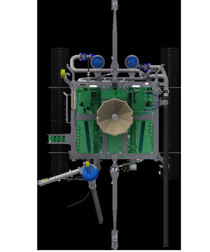
9 MS1000 Software System description The MS1000 Software Trencher Monitoring System is designed to help you land a trenching vehicle (trencher) over a pipeline. Each system has up to four profiling sonar heads mounted on the front and back of the vehicle. In addition, one forward-looking imaging sonar head is installed and used as a traditional Obstacle Avoidance Sonar. You will need a Sonar Processor computer to run the software and connect to the sonar heads. With the Trencher Monitoring option enabled in the MS1000 Software, you will be able to view the real-time detected pipe position. You can also view data from up to four sonar heads simultaneously. System diagram The system diagram identifies the main components of the MS1000 Software Trencher Monitoring System. Only the main connections between the units are shown. Detailed interface capabilities and power cables are not shown. Tip When installing the sonar heads, make a note of the location of each sonar head serial number. Label all cables connected to the Sonar Processor with each head serial number and location /1.2 7
 Note An internal dongle is also available, depending on your order.")
10 MS1000 Software Operator Manual This system diagram shows a four sonar-head configuration. If using two sonar heads, they will be mounted on the trencher centre-line both fore and aft. A B C D E Software key (dongle) Note An internal dongle is also available, depending on your order. Sonar Processor Obstacle Avoidance Sonar MS1000-compatible Sonar Heads The profiling sonar heads require an unobstructed view of the pipe and/or trench. Trencher /1.2

11 MS1000 Software Note You will need to enter the mounting offsets into the software. If your operator station is not close to the trencher, you may wish to measure the mounting offsets during installation for your convenience. Related topics Setting the mounting offsets, page 18 System units Topics Sonar Processor, page 9 MS1000-compatible Sonar Head, page 10 Sonar Processor The Sonar Processor is the computer that controls the MS1000 Software system. In this publication, the computer is referred to as the Sonar Processor. The Sonar Processor runs the MS1000 software that manages communication with the Sonar Head, performs all beamforming and image processing and presents the sonar imagery. The Sonar Processor communicates with the sonar through a USB, RS232/RS485 serial, or a standard Ethernet interface /1.2 9

12 MS1000 Software Operator Manual MS1000-compatible Sonar Head The Sonar Head transmits and receives an acoustic pulse when deployed underwater. The Sonar Head includes transmit and receive transducers and the electronics to generate the transmit pulse and digitize the received signal. The following Kongsberg Mesotech sonars are supported by the MS1000 Software Series Digital Sonar Head 1171 Series Digital Sonar Head 1007D Series Altimeter Single-Axis Heavy Duty Rotator ( ) /1.2
13 MS1000 Software Support information If you need technical support for your MS1000 Software you must contact your local dealer, or our support department. If you require maintenance or repair, contact your local dealer. You can contact us by phone at , or by at: If you need information about our other products, visit On our website you will also find a list of our dealers and distributors /1.2 11
14 MS1000 Software Operator Manual Getting started Topics Starting the MS1000 Software, page 12 Setting up your sonars, page 14 Adjusting the sonar views, page 17 Setting the mounting offsets, page 18 Setting the orientation of the sonar heads, page 20 Setting the profiling properties, page 20 Setting up the Trencher Monitoring window, page 23 Starting the MS1000 Software You must first power up the display and the Sonar Processor. After this you can start the MS1000 software. Prerequisites Any old versions of the MS1000 Software have been removed. The latest version of the MS1000 Software has been installed. All hardware units have been installed. To enable full Sonar Head operation, a software key (dongle) must be connected to the Sonar Processor s USB port. Alternatively, an internal dongle may be purchased /1.2
15 Getting started Note The dongle is not required for playback. To allow others to view data you have collected, you are free to make copies of the MS1000 Software and distribute them. Context The MS1000 software is not automatically started when the Sonar Processor is turned on. Double-click the MS1000 icon on the Sonar Processor desktop to start the software. Procedure 1 Power up the sonar heads. Note It may take up to 20 seconds for the MS1000 Software to connect to the sonar heads once the power is applied. 2 Turn on the Sonar Processor. Wait for the operating system to start up. 3 Log in to Windows. 4 Double-click the MS1000 icon on the Sonar Processor desktop to start the software. 5 Once the MS1000 software has started, observe that the presentation fills the entire screen. The software starts up using the same settings as the last time you used it. If these settings are acceptable, continue operation. If you wish to alter any of the settings, see the relevant procedures. 6 Make sure the MS1000 Software is set up for trencher monitoring. a b Click the MS1000 logo above the menu system on the right side of the presentation. Observe that the About MS1000 dialog box opens. Observe that Trencher Monitoring is included in the enabled options /1.2 13

16 MS1000 Software Operator Manual Note If this option does not appear, there may be a problem with your software key. Setting up your sonars If you are using your sonar for the first time, you must establish communications between the Sonar Head and the MS1000 Software. Context You can detect and set up the sonar heads using the System Configuration dialog box. Procedure 1 Click the Setup tab on the right side of the presentation. Observe that the Setup menu opens. 2 Click the Connect Sonar button. Observe that the System Configuration dialog box opens. 3 In the Devices list, select each port your Sonar Head is connected to /1.2
17 Getting started Tip If the expected port does not appear at first, click the Reset button to refresh the list of available ports. 4 Make sure the ports are configured correctly. a b Check the Enable for Head Control box. Uncheck the Multidrop box to reduce the time to detect each Sonar Head. Note If you have installed all sonar heads on one telemetry line, then you must check the Multidrop box. 5 Click the Detect Heads button. A progress bar will be shown as the MS1000 Software establishes communication with the sonar heads. When each Sonar Head has been detected, it will appear in the Devices list with details shown at the bottom of the dialog box. Tip If the Sonar Head cannot be detected, it may be programmed to a different baud rate than the factory default setting of 9600 bps. Click the Auto Detect button to detect any Sonar Heads using different baud rates. 6 After all the sonar heads are detected, rename each Sonar Head. a b c Select each default Sonar Head name in the Devices list (such as Head #1, for example). Observe the Serial Number for each Sonar Head. During installation, you will have noted the position of this Serial Number. In the Head Name field, enter in a name to identify the head according to its location on the trencher. Enter OAS for the Obstacle Avoidance Sonar (COM15 by default). Enter FORE PORT for the sonar mounted forward left (COM11 by default). Enter FORE STBD for the sonar mounted forward right (COM12 by default). Enter AFT PORT for the sonar mounted back left (COM13 by default). Enter AFT STBD for the sonar mounted back right (COM14 by default) /1.2 15

18 MS1000 Software Operator Manual Note If you have two sonar heads, rename them FORE and AFT. 7 Click Apply to save any changes you have made. 8 Click OK to close the System Configuration dialog box /1.2
19 Getting started Adjusting the sonar views Set up the layout so that you can view the data from all sonar heads simultaneously. Prerequisites The sonar heads must be running to perform this procedure. Procedure 1 If the sonar heads are not running, click the Run button on the Sonar tool bar. 2 Click the Display tab on the right side of the presentation. Observe that the Setup menu opens. 3 Click the + or - on the Layout button to select the desired layout option. You can arrange the view windows horizontally or vertically. Select Auto if you want the MS1000 Software to arrange your windows automatically. To interchange sonar view window locations, left-click on the first sonar view window. Observe that the mouse icon changes. Drag your mouse to the second sonar view window. Release the mouse button. 4 Scale each sonar view so that it is visible in a smaller window. a b Right-click in each sonar view. Observe that the context menu opens. Select Fit Image To Screen /1.2 17
20 MS1000 Software Operator Manual Result The following is an example of a possible sonar view layout. Setting the mounting offsets The mounting offsets are required to calibrate the position of each sonar head relative to a common reference point on the trencher. Prerequisites You need to measure the offsets before you configure them in the software. Select a reference point on the trencher that is common to all sonar heads. Measure the following offsets for each Sonar Head relative to the reference point. X Y Z Pitch Roll Yaw Positive Starboard Positive Forward Positive Up Positive Bow Up Positive Starboard Down Positive Clockwise /1.2

21 Getting started The sonar heads must be running to perform this procedure. Procedure 1 If the sonar heads are not running, click the Run button on the Sonar tool bar. 2 Right-click in any of the sonar views. Observe that the context menu opens. 3 Select Offsets. Observe that the Advanced Heads Setup dialog box opens. 4 Select each Sonar Head name in the list and enter the offsets you measured earlier into the Mounting Offsets boxes. 5 For the forward-looking imaging Obstacle Avoidance Sonar (OAS), un-check the Horizontal Mounting box. For the four profiling sonar heads, check the Horizontal Mounting box. Related topics System diagram, page /1.2 19
22 MS1000 Software Operator Manual Setting the orientation of the sonar heads The Orientation function allows you to specify which way the Sonar Head transducer is pointing. Prerequisites The sonar heads must be running to perform this procedure. Context This function determines how the image is plotted in the sonar view. If you set the orientation incorrectly, the image will be reversed. Procedure 1 If the sonar heads are not running, click the Run button on the Sonar tool bar. 2 Click the Operation tab on the right side of the presentation. Observe that the Operation menu opens. 3 Click the Orientation button to select an orientation. Match the orientation to the physical installation of the Sonar Head. For example, the sonar heads mounted in the Fore position are pointing forward (the domes face the front). The sonar heads mounted in the Aft position are pointing backwards (the domes face the back). The Obstacle Avoidance Sonar (OAS) dome can be pointing up or down. Related topics System diagram, page 7 Setting the profiling properties The profiling properties are used to generate the pipeline product profile. Context Set the profiling properties on the Profiling page of the Advanced Head Settings dialog box. This dialog box is only available when the Sonar Head is running /1.2

23 Getting started Note Good detection of the pipeline product profile is important if you wish to use the Trencher Monitoring window. Procedure 1 If the sonar heads are not running, click the Run button on the Sonar tool bar. 2 Click the Profiling tab on the right side of the presentation. Observe that the Profiling menu opens. 3 Click the Profiling Property button /1.2 21

24 MS1000 Software Operator Manual 4 Adjust the following parameters on the Profiling page for optimal pipeline product detection. Algorithm The First Return algorithm extracts the first point above the threshold within the Minimum Range and Maximum Range. The Peak Return algorithm extracts the peak point above the threshold within the Minimum Range and Maximum Range. Display Mode The Image and Profile mode displays both image data and profile points (for 3D views). Select this mode to properly view data in the Trencher Monitoring window. Scan Mode Enabling Multiping mode is not necessary when using the Trencher Monitoring window. Parameters The MS1000 Software will start looking for profile returns from the Minimum Range and stop looking above the Maximum Range. The signal level above the threshold needs to be maintained above the Minimum Width to be considered as a profile return. The Sample Interval is a read-only field and displays the sample resolution (used to measure the profile points). Threshold Curve Adjust the Threshold Curve to set the detection thresholds to different levels at different angles. This setting can be used to compensate for weaker returns at flatter grazing angles versus stronger returns at normal angles. Click the Reset button to reset the threshold curve to a flat line, giving the same threshold from 0 to 360 degrees. Related topics Monitoring the trencher, page /1.2

25 Getting started Setting up the Trencher Monitoring window Before you can monitor the trencher in the Trencher Monitoring window, you need to select which sonar heads to use, adjust the pipe diameter, and set up a background drawing. Context You can adjust the settings in the Trencher Monitoring Settings dialog box. Note The two Fore and Aft drop-down lists on the right side will be greyed out if you have enabled trencher monitoring for two sonar heads only. Procedure 1 If the sonar heads are not running, click the Run button on the Sonar tool bar. 2 Click the Setup tab on the right side of the presentation. Observe that the Setup menu opens. 3 Click the Trencher Monitoring button. Observe that the Trencher Monitoring Export dialog box opens. 4 If you want to export trencher monitoring data, select a COM port (such as COM16 in the default configuration), then click OK /1.2 23
26 MS1000 Software Operator Manual If you do not wish to export data, click Cancel. 5 Click the Settings button in the bottom-left corner of the Trencher Monitoring window. Observe that the Trencher Monitoring Settings dialog box opens. 6 Select which sonar heads to use. a b c Check the Select Heads box. In the Fore drop-down lists, select FORE PORT and FORE STBD. In the Aft drop-down lists, select AFT PORT and AFT STBD. 7 Drag the Pipe Diameter slider to a size that matches the actual pipe diameter. If there is no (or intermittent) detection of the pipe, try a larger pipe diameter. Tip Use the mouse scroll wheel or keyboard arrow keys to make fine adjustments. 8 Set up the background plan view trencher drawing. a b c d e f Select Set Plan View Scale. Click the Choose Image button. Navigate to C:\KML\MS1000_V0535 and select the file TrencherTop.bmp. This image will be used for the trencher plan view background. Tip Click the Reset button if the image appears at the wrong scale. In the Trencher Monitoring window, use the mouse to drag the M1 and M2 markers to two known points (relative to the reference point) on the trencher drawing. Press the Ctrl + arrow keys to make fine adjustments to the cursor positions on the drawing. Enter the known X and Y point coordinates into the M1 and M2 text fields in the Trencher Monitoring Settings dialog box. Enter X coordinates into the first text field, and Y coordinates into the second text field. Click Apply. 9 Set up the background rear view trencher drawing. a b c Select Set Rear View Scale. Click the Choose Image button. Navigate to C:\KML\MS1000_V0535 and select the file TrencherBack.bmp /1.2
27 Getting started d e f This image will be used for the trencher rear view background. In the Trencher Monitoring window, use the mouse to drag the M1 and M2 markers to two known points (relative to the reference point) on the trencher drawing. Press the Ctrl + arrow keys to make fine adjustments to the cursor positions on the drawing. Enter the known X and Y point coordinates into the M1 and M2 text fields in the Trencher Monitoring Settings dialog box. Enter X coordinates into the first text field, and Y coordinates into the second text field. Click Apply. 10 Close the Trencher Monitoring Settings dialog box /1.2 25
28 MS1000 Software Operator Manual Operational procedures Topics Monitoring the trencher, page 26 Exporting trencher monitoring data, page 29 Monitoring the trencher You can monitor the trencher in the Trencher Monitoring window. The Trencher Monitoring window allows you to view the real-time detected pipe position. Context The Trencher Monitoring window displays the top and rear view of the trencher, the plotting scale, the heading offset, the lateral offset, and the altitude above the pipe /1.2
29 Operational procedures Heading Offset: shown as an angle in degrees. A negative value represents the pipeline being offset counter clockwise to the centreline of the trencher. A positive value represents the pipeline being offset clockwise to the centreline of the trencher. Lateral Offset: the distance in millimetres (mm) from the centreline of the trencher. A negative value represents the pipeline being on the port side of the centreline. A positive value represents the pipeline being on the starboard side of the centreline. Altitude Above Pipe: the distance in metres from the pipe to the trencher reference point /1.2 27
30 MS1000 Software Operator Manual Procedure 1 If the sonar heads are not running, click the Run button on the Sonar tool bar. 2 Click the Setup tab on the right side of the presentation. Observe that the Setup menu opens. 3 Click the Trencher Monitoring button. Observe that the Trencher Monitoring Export dialog box opens. 4 If you want to export trencher monitoring data, select a COM port, then click OK. If you do not wish to export data, click Cancel. 5 Use the on-screen widget in the top-right corner of the Trencher Monitoring window to pan or zoom in and out of the window. Alternatively, click and drag with the mouse to pan or use the mouse scroll wheel to zoom in and out. 6 Observe the position of the yellow pipe relative to the trencher drawing and adjust the heading of the trencher as necessary. Related topics Setting the profiling properties, page /1.2
31 Operational procedures Exporting trencher monitoring data You can export trencher monitoring data to a serial port. Context The baud rate for the serial output is 9600 bps. The serial format is an ASCII string with the following format: $KSSMD,Hhhh.hh,Llll.ll,Aaaa.aa,Ddddd,Qq,*hh<CR><LF> $KSSMD = Header H = Heading Offset in degrees (2 decimal places) L = Lateral Offset in metres (2 decimal places) A = Altitude above pipe in metres (2 decimal places) D = Set Pipe Diameter in millimetres Q = Quality Flag (0, pipe is not detected; 1, pipe is detected) hh = Checksum (exclusive OR checksum between $ and *) Procedure 1 If the sonar heads are not running, click the Run button on the Sonar tool bar. 2 Click the Setup tab on the right side of the presentation. Observe that the Setup menu opens. 3 Click the Trencher Monitoring button. Observe that the Trencher Monitoring Export dialog box opens. 4 Select which COM port you wish to export the trencher monitoring status to. 5 Click OK. Observe that the Trencher Monitoring window opens /1.2 29
32 MS1000 Software Operator Manual Index A about comments... 5 constructive criticism... 5 feedback... 5 purpose of this manual... 5 registered trademarks... 5 software license... 5 software version... 5 suggestions... 5 target audience... 5 adjust sonar views Advanced Heads Setup dialog box setting the mounting offsets audience this manual... 5 B block diagram... 7 book purpose... 5 target audience... 5 C comments send us... 5 constructive criticism send us... 5 D description system... 7 drawing system diagram... 7 E exporting trencher monitoring data F feedback send us... 5 functional diagram... 7 H how to adjust sonar views export trencher monitoring data monitor the trencher power up set the mounting offsets set the orientation of the sonar heads set the profiling properties set up the sonar set up the Trencher Monitoring window I information support...11 introduction Sonar Head Sonar Processor... 9 K Kongsberg Mesotech support...11 L license software... 5 M manual purpose... 5 target audience... 5 monitoring trencher mounting offsets setting O office support...11 on power Orientation function setting the orientation of the sonar heads orientation of the sonar heads setting overview /1.2
33 Index P Sonar Head Sonar Processor... 9 power on procedure adjusting sonar views exporting trencher monitoring data monitoring the trencher powering up setting the mounting offsets setting the orientation of the sonar heads setting the profiling properties setting up the sonar setting up the Trencher Monitoring window Profiling function setting the profiling properties profiling properties setting publication purpose... 5 target audience... 5 purpose Sonar Head Sonar Processor... 9 this manual... 5 suggestions send us... 5 support information...11 switch on system description... 7 diagram... 7 System Configuration dialog box setting up the sonar T target audience this manual... 5 this manual purpose... 5 target audience... 5 trademarks registered... 5 trencher monitoring trencher monitoring data exporting Trencher Monitoring window exporting trencher monitoring data monitoring the trencher setting up R reader this manual... 5 registered trademarks... 5 V version software... 5 S setting mounting offsets orientation of the sonar heads profiling properties setting up sonar head Trencher Monitoring window software license... 5 version... 5 sonar head setting up Sonar Head introduction overview purpose Sonar Processor introduction... 9 overview... 9 purpose... 9 sonar views adjust /1.2 31
34 2018 Kongsberg Mesotech
Reference Manual. M3 Sonar. Multibeam Sonar
 Reference Manual M3 Sonar Multibeam Sonar M3 Sonar Multibeam sonar Reference Manual Release 1.3 This manual provides you with reference information required to operate and fully understand the commands,
Operator Manual. M3 Sonar. Portable Hydrographic System
 Operator Manual M3 Sonar Portable Hydrographic System M3 Sonar Portable Hydrographic System (PHS) Operator Manual Release 1.0 This manual provides you with the basic information required to operate the
Podium Data Analysis Software. User Manual. RCA40 Version
 RCA40 Version Issue 1.00 March 2003 Contents 1 Introduction 5 1.1 What is Podium? 5 1.2 About This Manual 5 1.3 Typographical Conventions 6 1.4 Getting Technical Support 6 2 Getting Started 7 2.1 System
SVP Manager Installation Manual
 SVP Manager Installation Manual This manual describes how to install the SVP Manager. 318213/A Jan 2008 Document history Document number: 318213 Rev. A January 2008 First version. The reader This operator
Podium Data Analysis Software. User Manual. SWIS10 Version
 SWIS10 Version Issue 1.00 March 2003 Contents 1 Introduction 5 1.1 What is Podium? 5 1.2 About This Manual 5 1.3 Typographical Conventions 6 1.4 Getting Technical Support 6 2 Getting Started 7 2.1 System
Simrad TD50 3D Visualisation software
 Simrad TD50 3D Visualisation software Reference Manual Release 1.3.x The purpose of this manual is to provide the descriptions and procedures required to allow for efficient use of the Simrad TD50. The
Teledyne PDS. Trailing Suction Hopper. Version April Teledyne RESON B.V. Stuttgartstraat AS Rotterdam The Netherlands
 Trailing Suction Hopper Teledyne PDS Version 1.1.0 April 2017 Teledyne RESON B.V. Stuttgartstraat 42-44 3047 AS Rotterdam The Netherlands Tel.: +31 (0)10 245 15 00 www.teledyne-reson.com Teledyne RESON
Podium Plus Data Analysis Software. User Manual. SWIS10 Version
 SWIS10 Version Issue 1.10 February 2005 Contents 1 Introduction 6 1.1 What is Podium Plus? 6 1.2 About This Manual 6 1.3 Typographical Conventions 7 1.4 Getting Technical Support 7 2 Getting Started 8
AEMLog Users Guide. Version 1.01
 AEMLog Users Guide Version 1.01 INTRODUCTION...2 DOCUMENTATION...2 INSTALLING AEMLOG...4 AEMLOG QUICK REFERENCE...5 THE MAIN GRAPH SCREEN...5 MENU COMMANDS...6 File Menu...6 Graph Menu...7 Analysis Menu...8
PENMOUNT DEVICE DRIVER USERS GUIDE FOR MICROSOFT WINDOWS
 PENMOUNT DEVICE DRIVER USERS GUIDE FOR MICROSOFT WINDOWS Version 2.4 16/Sep/ 15 Preface Disclaimer The information in this document is subject to change without notice. The manufacturer makes no representations
User s Manual. CW500Viewer IM CW500-61EN. 2nd Edition
 User s Manual CW500Viewer 2nd Edition Thank you for purchasing the CW500 Power Quality Analyzer. This manual explains the operating procedures of CW500Viewer, a software application included with the CW500.
StickFont Editor v1.01 User Manual. Copyright 2012 NCPlot Software LLC
 StickFont Editor v1.01 User Manual Copyright 2012 NCPlot Software LLC StickFont Editor Manual Table of Contents Welcome... 1 Registering StickFont Editor... 3 Getting Started... 5 Getting Started...
Reset Cursor Tool Clicking on the Reset Cursor tool will clear all map and tool selections and allow tooltips to be displayed.
 SMS Featured Icons: Mapping Toolbar This document includes a brief description of some of the most commonly used tools in the SMS Desktop Software map window toolbar as well as shows you the toolbar shortcuts
Simrad EK80. Software Release Note Introduction
 Simrad EK80 Software Release Note 1.12.2 Introduction This document describes the changes introduced with the new software version. Product: EK80 Software version: 1.12.2 This software controls all functionality
DesignWorks- CrystalWork Skillbuilder
 DesignWorks- CrystalWork Skillbuilder Crystal Shapes & Fills The following exercise will cover the basics of filling and editing a Crystal shape. For detailed CrystalWork software instructions, review
Teledyne PDS. Multibeam Calibration. Version January Teledyne RESON B.V. Stuttgartstraat AS Rotterdam The Netherlands
 Multibeam Calibration Teledyne PDS Version 2.0.4 January 2017 Teledyne RESON B.V. Stuttgartstraat 42-44 3047 AS Rotterdam The Netherlands Tel.: +31 (0)10 245 15 00 www.teledyne-reson.com Teledyne RESON
Software User s Manual
 1 About the manual 2 Navigating the manual 2 3 Opening the control panel 3 Control panel overview 4 Control panel settings 5 Calibrating the interactive pen display 6 Adjusting frequency and tracking (VGA
TOF-Watch SX Monitor
 TOF-Watch SX Monitor User manual Version 1.2 Organon (Ireland) Ltd. Drynam Road Swords Co. Dublin Ireland Contents General information... 3 Getting started... 3 File Window... 7 File Menu... 10 File Open
User Manual Version 1.1 January 2015
 User Manual Version 1.1 January 2015 - 2 / 112 - V1.1 Variegator... 7 Variegator Features... 7 1. Variable elements... 7 2. Static elements... 7 3. Element Manipulation... 7 4. Document Formats... 7 5.
ekaizen Lessons Table of Contents 1. ebook Basics 1 2. Create a new ebook Make Changes to the ebook Populate the ebook 41
 Table of Contents 1. ebook Basics 1 2. Create a new ebook 20 3. Make Changes to the ebook 31 4. Populate the ebook 41 5. Share the ebook 63 ekaizen 1 2 1 1 3 4 2 2 5 The ebook is a tabbed electronic book
Bosch Recording Station. Operating Manual
 Bosch Recording Station en Operating Manual Bosch Recording Station Table of Contents en 3 Table of Contents 1 Program Start/Login 5 1.1 Starting the Program 5 1.2 Logging on to the System 5 1.2.1 Logging
User Manual Australia
 User Manual Australia April 2009 EAZ0057B06A Rev. A Trademarks Acknowledgements Snap-on, ShopStream Connect, ETHOS, MODIS, SOLUS, SOLUS PRO, and Vantage PRO are trademarks of Snap-on Incorporated. All
[ Getting Started with Analyzer, Interactive Reports, and Dashboards ] ]
![[ Getting Started with Analyzer, Interactive Reports, and Dashboards ] ]](/thumbs/88/117545107.jpg "[ Getting Started with Analyzer, Interactive Reports, and Dashboards ] ]") Version 5.3 [ Getting Started with Analyzer, Interactive Reports, and Dashboards ] ] https://help.pentaho.com/draft_content/version_5.3 1/30 Copyright Page This document supports Pentaho Business Analytics
Version 5.3 [ Getting Started with Analyzer, Interactive Reports, and Dashboards ] ] https://help.pentaho.com/draft_content/version_5.3 1/30 Copyright Page This document supports Pentaho Business Analytics
TARGET LOGGER SOFTWARE MODULE ADDENDUM. EdgeTech 4 Little Brook Road West Wareham, MA _REV_B 3/8/2018
 TARGET LOGGER SOFTWARE MODULE ADDENDUM 0018974_REV_B 3/8/2018 EdgeTech 4 Little Brook Road West Wareham, MA 02576 Tel: (508) 291-0057 Fax: (508) 291-2491 www.edgetech.com ii The information, figures, and
IGSS 13 Configuration Workshop - Exercises
 IGSS 13 Configuration Workshop - Exercises Contents IGSS 13 Configuration Workshop - Exercises... 1 Exercise 1: Working as an Operator in IGSS... 2 Exercise 2: Creating a new IGSS Project... 28 Exercise
SIMPLE TEXT LAYOUT FOR COREL DRAW. When you start Corel Draw, you will see the following welcome screen.
 SIMPLE TEXT LAYOUT FOR COREL DRAW When you start Corel Draw, you will see the following welcome screen. A. Start a new job by left clicking New Graphic. B. Place your mouse cursor over the page width box.
DiBos/DiBos Micro. Operation Manual
 DiBos/DiBos Micro en Operation Manual DiBos/DiBos Micro Table of Contents en 3 Table of Contents 1 Program start/log-on 7 1.1 Starting the program 7 1.2 Logging on to the system 7 1.2.1 Logging on to
Amazing Designs Apps Instruction Manual
 Amazing Designs Apps Instruction Manual Amazing Designs Apps is a new embroidery software system from Amazing Designs that contains multiple features, in different toolpacks that are activated separately.
ezimagex2 User s Guide Version 1.0
 ezimagex2 User s Guide Version 1.0 Copyright and Trademark Information The products described in this document are copyrighted works of AVEN, Inc. 2015 AVEN, Inc. 4595 Platt Rd Ann Arbor, MI 48108 All
User manual Horus Movie Player 1
 User manual Horus Movie Player 1 REVISION HISTORY DATE VERSION AUTHOR October 2013 1.0 Bijwoordbeeld tekst en techniek User manual Horus Movie Player 2 1 WORKING WITH THE INSPECTION AND SURVEY SUITE 5
SaviSign Manager User Manual
 SaviSign Manager User Manual Digital Signage Management Software For The P100 Signage Player For use with Windows 7 or Higher Easy-to-use, powerful software Perfect for crafting digital signage displays!
set for a fixed view. Install the PTZ camera and the stationary camera in close proximity of each other
 CHAPTER 3 3.1 Object Tracking and Zooming Object Tracking provides you the real-time tracking and automatic magnification of a single moving object by the combination of one PTZ camera and one stationary
Palm Reader Handbook
 Palm Reader Handbook Copyright 2000-2002 Palm, Inc. All rights reserved. Graffiti, HotSync, the Palm logo, and Palm OS are registered trademarks of Palm, Inc. The HotSync logo and Palm are trademarks of
Maintenance Manual. M3 Sonar. Multibeam Sonar
 Maintenance Manual M3 Sonar Multibeam Sonar M3 Sonar Multibeam sonar Maintenance Manual Release 1.1 The purpose of this manual is to present the descriptions and drawings required to do basic maintenance
DiBos/DiBos Micro. Operation Manual
 DiBos/DiBos Micro en Operation Manual DiBos/DiBos Micro Table of Contents en 3 Table of Contents 1 Program Start/Login 7 1.1 Starting the Program 7 1.2 Logging on to the System 7 1.2.1 Logging on to the
Manual SmartGraph for Humlog 10
 Manual SmartGraph for Humlog 10 State: 10.12.2001 Version: V1.0 1 1 INTRODUCTION TO SMARTGRAPH... 4 1.1 Manage, Configure... 4 1.2 The Programme Interface... 4 1.2.1 Graphs... 5 1.2.2 Table... 6 1.2.3
FaxFinder Fax Servers
 FaxFinder Fax Servers Models: FF130 FF230 FF430 FF830 Client User Guide FaxFinder Client User Guide Fax Client Software for FaxFinder Series PN S000460B, Version B Copyright This publication may not be
User Guide. Model Temperature Datalogger Kit Model Temperature and Humidity Datalogger Kit Model SW276 Datalogging Software SW276
 User Guide Model 42265 Temperature Datalogger Kit Model 42275 Temperature and Humidity Datalogger Kit Model SW276 Datalogging Software SW276 Introduction Congratulations on your purchase of Extech Instrument
Getting Started with ShowcaseChapter1:
 Chapter 1 Getting Started with ShowcaseChapter1: In this chapter, you learn the purpose of Autodesk Showcase, about its interface, and how to import geometry and adjust imported geometry. Objectives After
IMAGE STUDIO LITE. Tutorial Guide Featuring Image Studio Analysis Software Version 3.1
 IMAGE STUDIO LITE Tutorial Guide Featuring Image Studio Analysis Software Version 3.1 Notice The information contained in this document is subject to change without notice. LI-COR MAKES NO WARRANTY OF
CellaVision Proficiency Software
 CellaVision Proficiency USER S MANUAL 2.3 CellaVision Proficiency Preface CellaVision is a trademark of CellaVision AB. All other trademarks used in this document are property of their respective owners.
TECHNICAL INFORMATION
 TECHNICAL INFORMATION MS1000 2U STANDARD PROCESSOR P/N 901-10320000 Specifications subject to change without notice 901-10327902 Iss. 1.0 KONGSBERG MESOTECH LTD. 1598 Kebet Way, Port Coquitlam B.C. Canada
TA Instrument Explorer. Getting Started Guide
 TA Instrument Explorer Getting Started Guide Revision A Issued May 2005 2005 by TA Instruments 109 Lukens Drive New Castle, DE 19720 Notice The material contained in this manual, and in the online help
Bombardier Business Aircraft Customer Services. Technical Publications. SmartPubs Viewer 3.0 User Guide. Updated January 2013 [2013]
![Bombardier Business Aircraft Customer Services. Technical Publications. SmartPubs Viewer 3.0 User Guide. Updated January 2013 [2013]](/thumbs/90/103657167.jpg "Bombardier Business Aircraft Customer Services. Technical Publications. SmartPubs Viewer 3.0 User Guide. Updated January 2013 [2013]") Bombardier Business Aircraft Customer Services Technical Publications SmartPubs Viewer 3.0 User Guide Updated January 2013 [2013] Table of Contents Application Views... 5 Collection View... 5 Manual View...
Bombardier Business Aircraft Customer Services Technical Publications SmartPubs Viewer 3.0 User Guide Updated January 2013 [2013] Table of Contents Application Views... 5 Collection View... 5 Manual View...
VMp Technical Support Phone: Online request:
 Copyright 2011 ViewCast Corporation. All rights reserved. ViewCast, Niagara SCX, ViewCast logo, Osprey, Niagara, SimulStream, Niagara logo, SchedulStream, GoStream, and ViewCast Media Platform (VMp) are
Navigator Software User s Manual. User Manual. Navigator Software. Monarch Instrument Rev 0.98 May Page 1 of 17
 User Manual Navigator Software Monarch Instrument Rev 0.98 May 2006 Page 1 of 17 Contents 1. NAVIGATOR SOFTWARE 2. INSTALLATION 3. USING NAVIGATOR SOFTWARE 3.1 STARTING THE PROGRAM 3.2 SYSTEM SET UP 3.3
MESURgauge Software. User s Guide
 MESURgauge Software User s Guide Thank you Thank you for purchasing MESURgauge software, a data collection and analysis program developed to: Measure Collect data from digital force gauges, torque gauges,
BUCKVIEW Advanced. User Guide
 BUCKVIEW Advanced User Guide Inside This Manual I. Inside This Manual... 2 II. Viewing and Managing Your Images... 3 Manage Image Folders...5 Manage Sites...6 Manage Locations...10 Erase Memory Card...14
Altering Layouts. Changing Font. Universal Engraving Machine. Chapter 18 Altering Layouts
 Universal Engraving Machine Changing Font Altering Layouts If you want to change the Font Style of your text. Left Click On the line you wish to change. If you wish to change more than one line, draw a
GV-VMS. New Feature Guide V VMSV FG-B
 GV-VMS New Feature Guide V15.10.1.0 VMSV151010-FG-B 2016 GeoVision, Inc. All rights reserved. Under the copyright laws, this manual may not be copied, in whole or in part, without the written consent of
VIMED JWEB Manual. Victorian Stroke Telemedicine. Version: 1.0. Created by: Grant Stephens. Page 1 of 17
 VIMED JWEB Manual Victorian Stroke Telemedicine Version: 1.0 Created by: Grant Stephens Page 1 of 17 1 Table of Contents 1 Table of Contents... 2 2 What is JWEB?... 4 3 Accessing JWEB... 4 3.1 For Mac
RIVA / Athena Pro-Series ECU
 RIVA / Athena Pro-Series ECU USING SOFTWARE (MAYA) Running Maya for First Time Once installed, Maya is available in the Start menu under Programs -> Maya, or from a desktop short cut, if created. The first
MESURgauge Software. User s Guide
 MESURgauge Software User s Guide MESURgauge Software Thank you! Thank you for purchasing MESURgauge software, a data collection and analysis program developed to: Measure Collect data from digital force
Virtual MODELA USER'S MANUAL
 Virtual MODELA USER'S MANUAL Virtual MODELA is a program that simulates the movement of the tool on the screen. Contents Contents Part 1 Introduction 1-1 System Requirements... 4 1-2 Overview of Virtual
Wizard PDS. Automated Perimeter Definition System. January Education and Training Center Wizard Date 5/4/2016. Page 1
 PDS Automated Perimeter Definition System January 2016 Page 1 Table of Contents Information Page 3 O Page 32 Operating Procedures Basic Operation Manually Reposition a Truss Snap to Rail Centerline Flip
Technology Assignment: Scatter Plots
 The goal of this assignment is to create a scatter plot of a set of data. You could do this with any two columns of data, but for demonstration purposes we ll work with the data in the table below. You
Welcome to MicroStation
 Welcome to MicroStation Module Overview This module will help a new user become familiar with the tools and features found in the MicroStation design environment. Module Prerequisites Fundamental knowledge
Vizit Pro User Manual
 Vizit Pro User Manual 1 Table of Contents Vizit Pro User Manual... 1 Using Vizit Pro... 3 The Vizit Pro User Interface... 3 Toolbars... 4 File Tab Toolbar... 4 Edit Tab Toolbar... 5 Annotations Tab Toolbar...
Mirasys N series. Network Video Recorder Quick Guide
 Mirasys N series Network Video Recorder Quick Guide 2006-2007 Mirasys Ltd. All rights reserved. No part of this document may be reproduced for any purpose, even in part. TRADEMARKS Mirasys and Mirasys
Spectrometer Visible Light Spectrometer V4.4
 Visible Light Spectrometer V4.4 Table of Contents Package Contents...3 Trademarks...4 Manual Driver and Application installation...5 Manual Application Installation...6 First Start of the Application...8
AEMLog users guide V User Guide - Advanced Engine Management 2205 West 126 th st Hawthorne CA,
 AEMLog users guide V 1.00 User Guide - Advanced Engine Management 2205 West 126 th st Hawthorne CA, 90250 310-484-2322 INTRODUCTION...2 DOCUMENTATION...2 INSTALLING AEMLOG...4 TRANSFERRING DATA TO AND
Océ Engineering Exec. Electronic Job Ticket
 Océ Engineering Exec Electronic Job Ticket Océ-Technologies B.V. Copyright 2004, Océ-Technologies B.V. Venlo, The Netherlands All rights reserved. No part of this work may be reproduced, copied, adapted,
AutoCollage 2008 makes it easy to create an AutoCollage from a folder of Images. To create an AutoCollage:
 Page 1 of 18 Using AutoCollage 2008 AutoCollage 2008 makes it easy to create an AutoCollage from a folder of Images. To create an AutoCollage: 1. Click on a folder name in the Image Browser. 2. Once at
SwiftView Quick-Start Guide. Revised for SwiftView
 SwiftView Quick-Start Guide Revised for SwiftView 9.2.3.4 Installing SwiftView To install SwiftView, place the SwiftView installer executable or MSI on your PC and doubleclick on it. You can download the
User Guide. FTR Reporter For more information, visit
 FTR Reporter 5.7.1 For more information, visit www.fortherecord.com TABLE OF CONTENTS INTRODUCTION... 5 Overview... 5 About This Document... 5 GETTING STARTED... 6 Installation... 6 Starting Reporter...
Student Quick Reference Guide
 Student Quick Reference Guide How to use this guide The Chart Student Quick Reference Guide is a resource for PowerLab systems in the classroom laboratory. The topics in this guide are arranged to help
Engine with Propeller Tutorial (Professional)
") Engine with Propeller Tutorial (Professional) Copyright 2017 FunctionBay, Inc. All rights reserved. User and training documentation from FunctionBay, Inc. is subjected to the copyright laws of the Republic
Engine with Propeller Tutorial (Professional) Copyright 2017 FunctionBay, Inc. All rights reserved. User and training documentation from FunctionBay, Inc. is subjected to the copyright laws of the Republic
Solo 4.6 Release Notes
 June9, 2017 (Updated to include Solo 4.6.4 changes) Solo 4.6 Release Notes This release contains a number of new features, as well as enhancements to the user interface and overall performance. Together
OpenForms360 Validation User Guide Notable Solutions Inc.
 OpenForms360 Validation User Guide 2011 Notable Solutions Inc. 1 T A B L E O F C O N T EN T S Introduction...5 What is OpenForms360 Validation?... 5 Using OpenForms360 Validation... 5 Features at a glance...
DJI GS PRO. User Manual V
 DJI GS PRO User Manual V1.4 2017.03 Video Tutorials Virtual Fence Mission 3D Map Area Mission Waypoint Flight Mission 2 2017 DJI All Rights Reserved. Contents Video Tutorials 2 Disclaimer 4 Warning 4 Introduction
AutoCAD 2009 User InterfaceChapter1:
 AutoCAD 2009 User InterfaceChapter1: Chapter 1 The AutoCAD 2009 interface has been enhanced to make AutoCAD even easier to use, while making as much screen space available as possible. In this chapter,
Introduction. Slide Basics. PowerPoint 2010 Slide Basics. Video: Slide Basics in PowerPoint About Slides. Page 1
 PowerPoint 2010 Slide Basics Introduction Page 1 PowerPoint includes all of the features you need to produce professionallooking presentations. When you create a PowerPoint presentation, it is made up
Viewing Listings. Viewing Listings with Multiple Photos. Viewing Enlarged Photos
 Found Listings Viewing Listings... 2 Printing Listings... 5 Street Map View... 6 Driving Directions... 9 Virtual Tour... 11 Viewing Virtual Tours... 12 Attach Fax Document to Listing... 13 1 Viewing Listings
Using Adobe Photoshop
 Using Adobe Photoshop 2 In this section we ll look at some essential things you need to know in order to use Photoshop effectively. First of all, we ll take a look at customising Photoshop s settings and
Profile Modeler Profile Modeler ( A SuperControl Product )
") Profile Modeler ( A SuperControl Product ) - 1 - Index Overview... 3 Terminology... 3 Launching the Application... 4 File Menu... 4 Loading a File:... 4 To Load Multiple Files:... 4 Clearing Loaded Files:...
Profile Modeler ( A SuperControl Product ) - 1 - Index Overview... 3 Terminology... 3 Launching the Application... 4 File Menu... 4 Loading a File:... 4 To Load Multiple Files:... 4 Clearing Loaded Files:...
User Guide for Avaya Scopia Control
 User Guide for Avaya Scopia Control Version 8.3 For Solution 8.3 March 2014 2000-2014 Avaya Inc. All intellectual property rights in this publication are owned by Avaya Inc. and are protected by United
Manual. User Reference Guide. Analysis Application (EMG) Electromyography Analysis
 Electromyography Analysis") Phone: (888) 765-9735 WWW.MINDWARETECH.COM User Reference Guide Manual Analysis Application Electromyography Analysis (EMG) Copyright 2014 by MindWare Technologies LTD. All Rights Reserved. 1 Phone: (614)
Phone: (888) 765-9735 WWW.MINDWARETECH.COM User Reference Guide Manual Analysis Application Electromyography Analysis (EMG) Copyright 2014 by MindWare Technologies LTD. All Rights Reserved. 1 Phone: (614)
DFS TOOLS 12.0 USER MANUAL
 DFS TOOLS 12.0 USER MANUAL 19.11.2012 Copyright 2012 Esko-Graphics Imaging GmbH, 25524 Itzehoe, Germany All rights reserved. This document and all information and instructions contained within are the
Photoshop and Lightroom for Photographers
 Topic 4 Panning and Zooming in Photoshop Learning Outcomes In this lesson, we will look at how we can pan and zoom to see our documents from a variety of angles. There are a number of ways to zoom in and
A QUICK TOUR OF ADOBE ILLUSTRATOR CC (2018 RELEASE)
") A QUICK TOUR OF ADOBE ILLUSTRATOR CC (2018 RELEASE) Lesson overview In this interactive demonstration of Adobe Illustrator CC (2018 release), you ll get an overview of the main features of the application.
A QUICK TOUR OF ADOBE ILLUSTRATOR CC (2018 RELEASE) Lesson overview In this interactive demonstration of Adobe Illustrator CC (2018 release), you ll get an overview of the main features of the application.
PediGait IP. Users Manual
 PediGait IP Users Manual April 2012 Table of Contents Clients Tab... 2 Open a Client file... 2 Delete Client file(s)... 2 Edit a Client... 3 Add a new client... 3 Add Comments to client files... 4 Profiles
GCC vinyl cutter, cutting plotter for sign making
 Plotter Setup In "Plotter Setup," you can choose "Plotter List," "Environment," "Pen," and so on. [Plotter list] In this area, you can choose the machine type and set some basic information for your plotter
Avigilon Gateway Web Client User Guide. Version 6.10
 Avigilon Gateway Web Client User Guide Version 6.10 2006-2018, Avigilon Corporation. All rights reserved. AVIGILON, the AVIGILON logo, AVIGILON CONTROL CENTER, ACC, and TRUSTED SECURITY SOLUTIONS. are
FREEDOM-Pad Installation and Operation
 FREEDOM-Pad Installation and Operation Quick Start Steps for installing FREEDOM-Pad Page 2 Desktop Install Overview Page 2 Mobile Device Installation Overview Page 2 Activating the Battery Page 2 Resetting
SolarSpeed Calculator INSTRUCTION MANUAL
 SolarSpeed Calculator INSTRUCTION MANUAL Login or register at https://solarspeed.avasco.be Registering Calculator. Click on Register at the homepage https://solarspeed.avasco.be. Fill in all fields (*
IRF90 - Rotating Focuser
 IRF90 - Rotating Focuser Part # 600180 REV092111 Page 1 Contents Introduction and Overview... 3 Limitations... 3 Packing List... 4 Installation... 5 Remove Existing Focuser... 5 Installing the Rotating
KIMOTO K I M O S E T T E R R I P. Kimosetter RIP User Guide 1. Revised: February 2015 U SER GUID E (FOR W INDOWS 7 )
") KIMOTO K I M O S E T T E R R I P U SER GUID E (FOR W INDOWS 7 ) Revised: February 2015 Kimosetter RIP User Guide 1 COPYRIGHT AND TRADEMARKS Kimosetter RIP User Guide Copyright Notices for the Software
KIMOTO K I M O S E T T E R R I P U SER GUID E (FOR W INDOWS 7 ) Revised: February 2015 Kimosetter RIP User Guide 1 COPYRIGHT AND TRADEMARKS Kimosetter RIP User Guide Copyright Notices for the Software
Getting Started. onset computer corporation. Software for HOBO Data Loggers & Devices
 onset computer corporation HOBOware Pro Software for HOBO Data Loggers & Devices Getting Started This software is furnished in accordance with a separate license agreement included with the software, and
Autodesk Fusion 360 Training: The Future of Making Things Attendee Guide
 Autodesk Fusion 360 Training: The Future of Making Things Attendee Guide Abstract After completing this workshop, you will have a basic understanding of editing 3D models using Autodesk Fusion 360 TM to
DOWNLOAD KIT CYCLOCOMPUTER INTRODUCTION. Download unit & Download Software [e-train Data Ver.3] for Windows 98/ME/2000/XP
![DOWNLOAD KIT CYCLOCOMPUTER INTRODUCTION. Download unit & Download Software [e-train Data Ver.3] for Windows 98/ME/2000/XP](/thumbs/78/78392561.jpg "DOWNLOAD KIT CYCLOCOMPUTER INTRODUCTION. Download unit & Download Software [e-train Data Ver.3] for Windows 98/ME/2000/XP") CYCLOCOMPUTER Download unit & Download Software [e-train Data Ver.3] for Windows 98/ME/2000/XP 0365510 (ENG) 3 INTRODUCTION The CC-TR100 Download Kit contains the software e-train Data TM Ver. 3 and the
CYCLOCOMPUTER Download unit & Download Software [e-train Data Ver.3] for Windows 98/ME/2000/XP 0365510 (ENG) 3 INTRODUCTION The CC-TR100 Download Kit contains the software e-train Data TM Ver. 3 and the
Speedway. Body. (S) on the Sketch toolbar. Fig. 1
 on the Sketch toolbar. Fig. 1") Chapter 1 A. New Part. Step 1. Click File Menu > New. Speedway Body Step 2. Click Part from the list and click OK, Fig. 1. B. Sketch Construction Rectangle. Step 1. Click Right Plane in the Feature Manager
Chapter 1 A. New Part. Step 1. Click File Menu > New. Speedway Body Step 2. Click Part from the list and click OK, Fig. 1. B. Sketch Construction Rectangle. Step 1. Click Right Plane in the Feature Manager
CyberComm Pro Data Acquisition Software Installation & User Guide
 CyberComm Pro 2.2.3 Data Acquisition Software Installation & User Guide ph 1100 and ph 2100 Bench ph and Bench ph/ion Meter Technology Made Easy... 68X090822 rev 1 Aug 2002 2 PREFACE Thank you for selecting
GIS DATA SUBMISSION USER GUIDE. Innovation and Networks Executive Agency
 Innovation and Networks Executive Agency GIS DATA SUBMISSION USER GUIDE Innovation and Networks Executive Agency (INEA) W910 Chaussée de Wavre 910 B-1049 Brussels, Belgium Tel: +32 (0)2 29 95252 Fax: +32
User's Guide. Temperature / Humidity Datalogger. Model 42270
 User's Guide Temperature / Humidity Datalogger Model 42270 Warranty EXTECH INSTRUMENTS CORPORATION warrants this instrument to be free of defects in parts and workmanship for one year from date of shipment
Expression Design Lab Exercises
 Expression Design Lab Exercises Creating Images with Expression Design 2 Beaches Around the World (Part 1: Beaches Around the World Series) Information in this document, including URL and other Internet
TECHNICAL INFORMATION
 TECHNICAL INFORMATION MS1000 2U SONAR PROCESSOR SMD P/N 901-10340000 Specifications subject to change without notice 901-10347902 Iss. 1.0 KONGSBERG MESOTECH LTD. 1598 Kebet Way, Port Coquitlam B.C. Canada
Lens Selection Software. User Manual
 Lens Selection Software User Manual Legal Information User Manual 2018 Hangzhou Hikvision Digital Technology Co., Ltd. About this Manual This Manual is subject to domestic and international copyright protection.
Web Viewer Guide. HiPER LOOK Version Copyright 2016 PIXIA Corp. All Rights Reserved.
 Web Viewer Guide 2016 HiPER LOOK Version 1.4.16.0 Copyright 2016 PIXIA Corp. All Rights Reserved. Table of Contents 1 System Requirements... 5 1.1 Prerequisites... 5 1.2 Web Browser... 5 2 HiPER LOOK Web
VANGUARD LOAD TAP CHANGER ANALYZER (LTCA) VERSION 2.xx SOFTWARE MANUAL. LTCA-10, LTCA-40, WRM-10P, WRM-40, TRM-20, TRM-40, TRM-203, and TRM-403
 VERSION 2.xx SOFTWARE MANUAL. LTCA-10, LTCA-40, WRM-10P, WRM-40, TRM-20, TRM-40, TRM-203, and TRM-403") VANGUARD LOAD TAP CHANGER ANALYZER (LTCA) VERSION 2.xx SOFTWARE MANUAL For Use with Vanguard s LTCA-10, LTCA-40, WRM-10P, WRM-40, TRM-20, TRM-40, TRM-203, and TRM-403 Load Tap Changer Analyzers and Winding
VANGUARD LOAD TAP CHANGER ANALYZER (LTCA) VERSION 2.xx SOFTWARE MANUAL For Use with Vanguard s LTCA-10, LTCA-40, WRM-10P, WRM-40, TRM-20, TRM-40, TRM-203, and TRM-403 Load Tap Changer Analyzers and Winding
The principles of CCTV design in VideoCAD
 The principles of CCTV design in VideoCAD By Stanislav Utochkin, cctvcad.com CCTV focus readers have already had an opportunity to read about VideoCAD in the past issues. This is the only specialised program