DEEP SEA ELECTRONICS
|
|
|
- Ethan Joseph
- 5 years ago
- Views:
Transcription

1 COMPLEX SOLUTIONS MADE SIMPLE DEEP SEA ELECTRONICS DSE SCADA Suite Software Document Number ISSUE 3 Author: Anthony Manton
2 DEEP SEA ELECTRONICS PLC Highfield House Hunmanby North Yorkshire YO14 0PH ENGLAND Sales Tel: +44 (0) Sales Fax: +44 (0) sales@deepseaplc.com Website : DSE SCADA Suite Software Manual Deep Sea Electronics Plc All rights reserved. No part of this publication may be reproduced in any material form (including photocopying or storing in any medium by electronic means or other) without the written permission of the copyright holder except in accordance with the provisions of the Copyright, Designs and Patents Act Applications for the copyright holder s written permission to reproduce any part of this publication should be addressed to Deep Sea Electronics Plc at the address above. The DSE logo and the names DSEUltra, DSEControl, DSEPower, DSEExtra, DSEMarine and DSENet are UK registered trademarks of Deep Sea Electronics PLC. Any reference to trademarked product names used within this publication is owned by their respective companies. Deep Sea Electronics Plc reserves the right to change the contents of this document without prior notice. Amendments List Issue Comments Minimum SCADA Suite Version required 1 Initial release 2 Support for 8600 V2 and 8700 V2 controllers Support for display and 8680 bus tie controller Typeface: The typeface used in this document is Arial. Care should be taken not to mistake the upper case letter I with the numeral 1. The numeral 1 has a top serif to avoid this confusion. 2
3 TABLE OF CONTENTS 1 DESCRIPTION INSTALLATION INSTRUCTIONS SOFTWARE INSTALLATION MINIMUM SYSTEM REQUIREMENTS INSTALLATION TROUBLESHOOTING SOFTWARE INSTALLATION WINDOWS WINDOWS VISTA WINDOWS XP WINDOWS NT, WINDOWS MILLENIUM, WINDOWS 98, WINDOWS 95, WINDOWS APPLE MAC, WINDOWS CE, PALM OS, SMARTPHONE, PDA HARDWARE INSTALLATION RS CONFIGURING THE SCADA SUITE PROPERTIES SAVING FOR USE WITH DSE8005 SCADA SUITE PC SOFTWARE SAVING FOR USE WITH DSE COLOUR OVERVIEW DISPLAY USING THE SCADA SUITE SYSTEM CONFIG RUNNING EDITOR AUTOSTART CONTROLLER HOME ENGINE GENERATOR BUS ALARMS I/O ABOUT MAINS CONTROLLER HOME UTILITY BUS ALARMS I/O ABOUT BUS TIE CONTROLLER HOME BUS ALARMS I/O ABOUT
4 1 DESCRIPTION This manual covers the operation of the DSE SCADA Suite software for DSE8600 / DSE8700 series synchronising modules. Separate manuals cover the remaining DSE modules supported by the software. The Help section of the software contains links to these documents, copied onto the PC during the software installation process. The DSE configuration suite allows the DSE8600 / DSE8700 family of modules to be connected to a PC via Belden 9841 RS485 cable. The SCADA suite should only be used by competent, qualified personnel, as changes to the operation of the module may have safety implications on the panel / generating set to which it is fitted. Access to the settings in the controller, may be barred by a security code set by the generator provider. The information contained in this manual should be read in conjunction with the information contained in the appropriate module documentation. A separate manual deals with the operation of the individual module (See section entitled Bibliography elsewhere in this document). 4
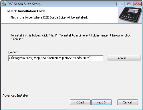
5 Installation 2 INSTALLATION INSTRUCTIONS 2.1 SOFTWARE INSTALLATION MINIMUM SYSTEM REQUIREMENTS Operating System Monitor Communications Windows 7, Windows Vista, Windows XP or Windows 2000 with Microsoft.Net 2.0 framework 17 inch recommended (1024 x 768 resolution) RS485 port required. NOTE: - As DSE configuration software for Windows is a 32 or 64 bit application requiring Microsoft.net 2 framework, it will not operate on Windows 2.0, 3.0, 3.1,3.11, 95, 98 or Me. NOTE: - Microsoft.Net 2.0 Framework can be obtained from Microsoft s website. Alternatively, it is included in the DSE Configuration Suite Software CD version which can be obtained on CD from Deep Sea Electronics PLC (DSE Part number ) or by downloading the CD version from the DSE website. NOTE: - Exit all other programs before installing the software. It is recommended that any earlier releases of the software be uninstalled prior to installing this version. NOTE: - Please register online at Once registered you will be able to download updates to the software to ensure that you always have access to the latest features INSTALLATION Insert the Software CD into the CD-ROM drive on the PC. The CD will then Auto-run if this feature is enabled on your PC. Alternatively: Double click on Computer Double click on CD-ROM Drive Double click CDSetup Click Next to continue
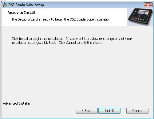
6 Installation Click Next to continue. Click Install to continue. 6

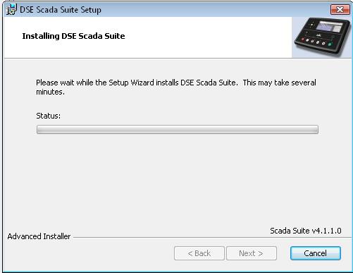
7 Installation 7
8 Installation TROUBLESHOOTING SOFTWARE INSTALLATION It is very rare that problems are encountered when installing the system, however if problems arise, use the following checklist to troubleshoot your software installation WINDOWS 7 32 bit and 64 bit versions Ensure the operating system is logged onto using an Administrator Account. Failure to do this results in installation failure due to incorrect user permissions disallowing registration of some parts of the SCADA Suite Software. When installing the software, instead of clicking the icon with the left mouse button, click on the installation icon with the right mouse button, then select Run as Administrator. Ensure the operating system is fully up to date using the Microsoft Windows Update facility. Ensure that Windows Installer is fully up to date using the Microsoft Windows Update facility. Ensure the operating system has Microsoft.net 2 Framework redistributable (for x86) installed and is fully up to date. This is available from Microsoft s website WINDOWS VISTA 32 bit and 64 bit versions Ensure the operating system is logged onto using an Administrator Account. Failure to do this results in installation failure due to incorrect user permissions disallowing registration of some parts of the SCADA Suite Software. When installing the software, instead of clicking the icon with the left mouse button, click on the installation icon with the right mouse button, then select Run as Administrator. Ensure the operating system is fully up to date using the Microsoft Windows Update facility. Ensure that Windows Installer is fully up to date using the Microsoft Windows Update facility. Ensure the operating system has Microsoft.net 2 Framework redistributable (for x86) installed and is fully up to date. This is available from Microsoft s website WINDOWS XP Ensure the operating system is logged onto using an Administrator Account. Failure to do this results in installation failure due to incorrect user permissions disallowing registration of some parts of the SCADA Suite Software. Ensure the operating system is fully up to date using the Microsoft Windows Update facility. Ensure that Windows Installer is fully up to date using the Microsoft Windows Update facility. Ensure the operating system has Microsoft.net 2 Framework redistributable (for x86) installed and is fully up to date. This is available from Microsoft s website WINDOWS NT, WINDOWS MILLENIUM, WINDOWS 98, WINDOWS 95, WINDOWS 3.1 DSE Configuration Suite does not support these operating systems. It is recommended that the system is operated under Windows 7, Windows Vista or Windows XP operating systems APPLE MAC, WINDOWS CE, PALM OS, SMARTPHONE, PDA DSE Configuration Suite requires a Windows Personal Computer (PC). It is recommended that the system is operated under Windows 7, Windows Vista or Windows XP operating systems. 8


 Set to Half Duplex, Autogating with CTS")
 Set to Half Duplex, Autogating with")
151 220 2500 Web: http://www.brainboxes.")
9 Installation 2.2 HARDWARE INSTALLATION 2.3 RS485 All DSE modules must be connected to the PC RS485 port using RS485 rated cable such as Belden Recommended PC Serial Port add-ons (for computers without internal RS485 port). Remember to check these parts are suitable for your PC. Consult your PC supplier for further advice. Brainboxes PM154 PCMCIA RS485 card (for laptops PCs) Set to Half Duplex, Autogating with CTS True set to enabled Brainboxes VX-023 ExpressCard 1 Port RS422/485 (for laptops and nettop PCs) Brainboxes UC320 PCI Velocity RS485 card (for desktop PCs) Set to Half Duplex, Autogating with CTS True set to enabled Brainboxes PX-324 PCI Express 1 Port RS422/485 (for desktop PCs) Supplier: Brainboxes Tel: +44 (0) Web: Sales:sales@brainboxes.com NB DSE Have no business tie to Brainboxes. Over many years, our own engineers have used these products and are happy to recommend them. 9


10 Operation Graphical Setup 3 CONFIGURING THE SCADA SUITE To run the SCADA Suite Editor Software click the Windows start button or depending upon your version of Windows. In the Programs section of the computer s START menu, select DEEP SEA ELECTRONICS PLC DSE SCADA suite configuration tool : This program allows the creation of a custom graphical interface for the SCADA Suite program or DSE8003 remote colour overview display module. To add devices to the system, drag them from the side bar to the canvas. Example of an entire system : When adding mains or generator parts to the canvas, it is not necessary to specify the controller type, this is automatically made when the SCADA suite communicates with the controllers. The software is compatible with DSE8610, DSE8660, DSE8680, DSE8710 and DSE8760 controllers. Alignment tools, load, save etc are provided in the modules menu bar and associated toolbar at the of the graphical editor screen.
 and whether the")


11 Operation Graphical Setup 3.1 PROPERTIES The properties section is used to setup the communications with the controller and set the graphical properties of the display such as the controller s name (ie Gen1) and whether the symbol appears above or below the bus. BusGroup allows the symbol to belong on the same generator bus as others. For example the display can show two independent generator busses, not connected. Example: BusGroup 1 Example: BusGroup SAVING FOR USE WITH DSE8005 SCADA SUITE PC SOFTWARE Save the file to the installation folder (usually C:\Program Files\Deep Sea Electronics PLC\DSE Scada Suite), with the filename DSEScadaSuite.xml. When SCADA Suite is started, this configuration file is automatically loaded by the software. 3.3 SAVING FOR USE WITH DSE COLOUR OVERVIEW DISPLAY Save the file to the root of a USB pen drive with the filename DSEScadaSuite.xml. Insert this pen drive into the USB host socket of the DSE colour overview display. When the DSE8003 display is powered up, this configuration file is automatically loaded. Operation of the DSE8003 display is covered in: DSE publication DSE8003 colour display operator manual. USB Host Socket for configuration by USB pen drive device. 11

12 Operation - System 4 USING THE SCADA SUITE To run the SCADA Suite Software program click the Windows start button or depending upon your version of Windows. Then select All Programs - Deep Sea Electronics PLC DSE SCADA Suite After a short delay to load the application, the main display is shown. The layout of this screen is application dependant and shows a representative diagram of the system. 4.1 SYSTEM The image below shows an example with two DSE8610 s and two DSE8660 s controller. Clicking the mouse with the left mouse button in the vicinity of the generator or mains icons will change the display to show the relevant control and instrumentation page. Clicking the mouse with the right mouse button in the vicinity of the generator or mains icons will open the generator Running Editor. Clicking the CONFIG button allows configuration of the application options. The colour of the generator / mains symbols change dependant upon level of the alarm. Gen Icon Mains Icon Colour Description Grey Controller is offline (no communication) Light Blue Green Yellow Red Controller is online (communicating) in STANDBY Any mode Controller is started/active or Engine/Generator is RUNNING Any mode Controller has a WARNING alarm present Controller has a SHUTDOWN or electrical trip alarm present 4.2 CONFIG Clicking the CONFIG button on the System page allows configuration of the application options.


13 Operation - System This allows configuration of the display parameters and selection of the alarm sounds. If enabled, then the clocks of all attached modules will be immediately synchronised with the local PC clock and then once a day. thereafter. 4.3 RUNNING EDITOR Clicking the mouse with the right mouse button in the vicinity of the generator or mains icons on the System page will open the generator Running Editor. Changes made with the Running Editor take place immediately the value is changed. There is no need to save the changes. These parameters are also changed from the module fascia, DSE Config Suite SCADA section and by Modbus RTU command from a suitably configured Master device. Parameter Generator Priority Parallel Power (Min) Parallel Power (Max) Parallel Power Factor Description Generator Run Priority for the Load Demand scheme This is the bottom of the load ramp. When the generator joins the bus, it will ramp up from this setting after closing the breaker. When the generator leaves the bus, it will ramp down to this setting before opening the breaker. The power level to be produced by the generator when in mains parallel mode (fixed export mode). The power factor to be supplied by the generator when in mains parallel mode (fixed export mode). 13
14 Operation Autostart Controller 4.4 AUTOSTART CONTROLLER HOME Genset Identity, Status and overview is shown at the top of every page. Genset and Site Identity are set using the DSE Config Suite Software. Control buttons to mimic the module s own fascia mounted buttons. Availability of some buttons depends upon the module type. The vertical green bar shows the module s current operating mode. Indicates the currently selected page. Click the buttons to change the page.
15 Operation Autostart Controller ENGINE Depending upon module configuration and/or CAN ECU support, some meters may not be displayed. 15
 power factor is lagging power")
16 Operation Autostart Controller GENERATOR Indicates that this is page 1 of 9 in this section. Press to move between the different pages including bargraph display: In line with normal convention : Positive (+) power factor is lagging power factor Negative (-) power factor is leading power factor 16

17 Operation Autostart Controller BUS Indicates that this is page 1 of 3 in this section. Press to move between the different pages including bargraph display: 17
18 Operation Autostart Controller ALARMS Indicates that this is page 1 of 2 in this section. Press to move between the current alarms and the past event log : Alarm level Warning Electrical trip Shutdown ECU code Colour/Title graphic 18
19 Operation Autostart Controller I/O Shows the diagnostic status of the controller s Inputs and Outputs. Indicates that this is page 1 of 2 in this section. Press outputs: to move between the inputs and. 19
20 Operation Autostart Controller ABOUT Shows the PC Software and Module firmware version numbers. 20
21 Operation Mains Controller 4.5 MAINS CONTROLLER HOME
22 Operation Mains Controller UTILITY Indicates that this is page 1 of 9 in this section. Press to move between the different pages. 22
23 Operation Mains Controller BUS Indicates that this is page 1 of 3 in this section. Press to move between the different pages. 23


24 Operation Mains Controller ALARMS Indicates that this is page 1 of 2 in this section. Press to move between the current alarms and the past event log : Alarm level Warning Electrical trip Shutdown ECU code Colour/Title graphic 24
25 Operation Mains Controller I/O Indicates that this is page 1 of 2 in this section. Press outputs: to move between the inputs and. 25
26 Operation Mains Controller ABOUT Shows the PC Software and Module firmware version numbers. 26
27 Operation Bus Tie Controller 4.6 BUS TIE CONTROLLER HOME BUS Press bargraphs to move between the dials and the.

28 Operation Bus Tie Controller ALARMS Press to move between the current alarms and the past event log : Alarm level Warning Electrical trip Colour/Title graphic. 28


29 Operation Bus Tie Controller I/O Press to move between the different pages. 29

30 Operation Bus Tie Controller ABOUT Shows the PC Software and Module firmware version numbers. 30
31 This Page Intentionally Blank
DEEP SEA ELECTRONICS PLC DSE8005 SCADA Suite PC Software Manual
 DEEP SEA ELECTRONICS PLC DSE8005 SCADA Suite PC Software Manual Document Number 057-128 Author: Anthony Manton 057-128 ISSUE: 8 DSE8005 SCADA Suite PC Software Manual DEEP SEA ELECTRONICS PLC Highfield
DEEP SEA ELECTRONICS PLC
 DEEP SEA ELECTRONICS PLC DSE857 Configuration Suite PC Software and Operator Manual Document Number: 057-219 Author: Tony Manton DSE857 Configuration Suite PC Software and Operator Manual ISSUE 1 DSE857
DEEP SEA ELECTRONICS
 COMPLEX SOLUTIONS MADE SIMPLE DEEP SEA ELECTRONICS DSE8600 Series PC configuration suite Document Number 057-119 Author: Anthony Manton 8600 Configuration Suite Software Manual ISSUE 2 8600 Configuration
DEEP SEA ELECTRONICS PLC DSE334 Configuration Suite Software Manual
 DEEP SEA ELECTRONICS PLC DSE334 Configuration Suite Software Manual Document Number 057-156 Author: Paul Gibbons DSE334 Configuration Suite Software Manual ISSUE 1 DSE334 Configuration Suite Software Manual
DEEP SEA ELECTRONICS PLC
 DEEP SEA ELECTRONICS PLC DSE2133 DSEnet RTD / Thermocouple Input Expansion Module Operator Manual Document number 057-140 Author : Anthony Manton DSE2131 DSEnet RTD / Thermocouple Input Expansion Module
DEEP SEA ELECTRONICS PLC
 DEEP SEA ELECTRONICS PLC DSE855 USB to Ethernet Convertor Operator Manual Document Number: 057-205 Author: Anthony Manton DSE855 USB to Ethernet Convertor Operator Manual ISSUE 4 DSE855 USB to Ethernet
DEEP SEA ELECTRONICS PLC DSEWebNet PC Internet Browser Software Manual
 DEEP SEA ELECTRONICS PLC DSEWebNet PC Internet Browser Software Manual Document Number: 057-168 Author: Ashley Senior ISSUE: 5 DSEWebNet PC Internet Browser Software Manual DEEP SEA ELECTRONICS PLC Highfield
DSE2548 DSENET OUTPUT EXPANSION MODULE. DSEGenset DSE2548 COMPREHENSIVE FEATURE LIST TO SUIT A WIDE VARIETY OF GEN-SET APPLICATIONS
 DSEGenset DSE2548 DSENET OUTPUT EXPANSION MODULE ENVIRONMENTAL TESTING STANDARDS ELECTRO-MAGNETIC COMPATIBILITY BS EN 61000-6-2 EMC Generic Immunity Standard for the Industrial Environment BS EN 61000-6-4
DEEP SEA ELECTRONICS PLC
 DEEP SEA ELECTRONICS PLC 7xx series configuration software for Windows Software Manual Author Anthony Manton Deep Sea Electronics Plc Highfield House Hunmanby Industrial Estate North Yorkshire YO14 0PH
DEEP SEA ELECTRONICS PLC DSE103 MK II Speed Switch Operators Manual
 DEEP SEA ELECTRONICS PLC DSE103 MK II Speed Switch Operators Manual Document number 057-135 Author : Paul Gibbons DSE103 MKII Operator Manual Issue 1 Deep Sea Electronics Plc Highfield House Hunmanby North
DSEEXTRA. DSE860 RS232 Ethernet Adaptor DSE865 RS485 Ethernet Adaptor Document Number Author : Anthony Manton
 COMPLEX SOLUTIONS MADE SIMPLE DSEEXTRA DSE860 RS232 Ethernet Adaptor DSE865 RS485 Ethernet Adaptor Document Number 057-099 Author : Anthony Manton Deep Sea Electronics Plc Highfield House Hunmanby North
DEEP SEA ELECTRONICS PLC
 DEEP SEA ELECTRONICS PLC 5xxx series configuration software for Windows For 55xx series controllers. Authors Anthony Manton Deep Sea Electronics Plc Highfield House Hunmanby Industrial Estate North Yorkshire
DEEP SEA ELECTRONICS PLC
 COMPLEX SOLUTIONS MADE SIMPLE DEEP SEA ELECTRONICS PLC DSE705 ATS CONTROL MODULE OPERATING MANUAL Deep Sea Electronics Plc Highfield House Hunmanby North Yorkshire YO14 0PH ENGLAND Sales Tel: +44 (0) 1723
DSEPOWER. DSE8721 Colour Remote Display Module. Document number Author : Anthony Manton
 DSEPOWER DSE8721 Colour Remote Display Module Document number 057-126 Author : Anthony Manton Part No. 057-115 DSE8721 OPERATING MANUAL ISSUE 3.1 21/09/2010 ADM 1 DSE8721 Control & Instrumentation System
DEEP SEA ELECTRONICS PLC
 COMPLEX SOLUTIONS MADE SIMPLE. DEEP SEA ELECTRONICS PLC DSE4130 AUTOMATIC TRANSFER SWITCH CONTROL MODULE OPERATING MANUAL Deep Sea Electronics Plc Highfield House Hunmanby North Yorkshire YO14 0PH ENGLAND
DSEPOWER. DSE7520 MK1 Mains Control Module. Document Number Author : Anthony Manton
 DSEPOWER DSE7520 MK1 Mains Control Module Document Number 057-090 Author : Anthony Manton Deep Sea Electronics Plc Highfield House Hunmanby North Yorkshire YO14 0PH ENGLAND Sales Tel: +44 (0) 1723 890099
DSE8610 SYNCHRONISING AUTO START LOAD SHARE CONTROL MODULE DSE COMPREHENSIVE FEATURE LIST TO SUIT A WIDE VARIETY OF LOAD SHARE APPLICATIONS FEATURES
 DSE DSE8610 SYNCHRONISING AUTO START LOAD SHARE CONTROL MODULE FEATURES ENVIRONMENTAL TESTING STANDARDS ELECTRO MAGNETIC COMPATIBILITY BS EN 61000-6-2 EMC Generic Immunity Standard for the Industrial Environment
DSEULTRA DSE3110 Series Control Module
 DSEULTRA DSE3110 Series Control Module 057-086 Author : Anthony Manton DSE Model 3000 Series Control and Instrumentation System Operators Manual Deep Sea Electronics Plc Highfield House Hunmanby North
DEEP SEA ELECTRONICS PLC DSE8610 Control Module
 DEEP SEA ELECTRONICS PLC DSE8610 Control Module Document number 057-115 Author : Anthony Manton DSE8610 Operator Manual Issue 5 DSE8610 Control & Instrumentation System Operators Manual Deep Sea Electronics
DSEPOWER DSE7510 Control Module Document Number
 DSEPOWER DSE7510 Control Module Document Number 057-088 Author : Anthony Manton http://bestgenerator.spb.ru/?page_id=6765 Deep Sea Electronics Plc Highfield House Hunmanby North Yorkshire YO14 0PH ENGLAND
DEEP SEA ELECTRONICS PLC
 COMPLEX SOLUTIONS MADE SIMPLE. DEEP SEA ELECTRONICS PLC DSE5520 AUTOMATIC MAINS FAILURE CONTROL MODULE OPERATING MANUAL Deep Sea Electronics Plc Highfield House Hunmanby North Yorkshire YO14 0PH ENGLAND
DEEP SEA ELECTRONICS PLC DSE334 ATS Controller Operators Manual
 DEEP SEA ELECTRONICS PLC DSE334 ATS Controller Operators Manual Document Number 057-154 Author: Allan Jones DSE 334 ATS Controller Operators Manual Issue 1 DSE 334 ATS Controller Operators Manual Deep
TYPICAL WIRING DIAGRAM A larger diagram is available in the operators manual. SEA ELECTRONICS 8620 INSTALLATION INSTRUCTIONS ISSUE 1
 TYPICAL WIRING DIAGRAM A larger diagram is available in the operators manual. DEEP SEA ELECTRONICS 8620 INSTALLATION INSTRUCTIONS 053-129 ISSUE 1 ACCESSING THE FRONT PANEL CONFIGURATION EDITOR. Ensure
DSEULTRA DSE6100 Series Control Module Document Number
 DSEULTRA DSE6100 Series Control Module Document Number 057-095 Author : Anthony Manton http://bestgenerator.spb.ru/?page_id=6765 DSE Model 6000 Series Control and Instrumentation System Operators Manual
DEEP SEA ELECTRONICS PLC
 DEEP SEA ELECTRONICS PLC DSE892 SNMP Gateway Manual Document Number : 057-179 Author : Anthony Manton DSE892 SNMP Gateway Manual ISSUE 1 DSE892 SNMP Gateway Manual Deep Sea Electronics Plc Highfield House
DSE2510/20 REMOTE DISPLAY MODULES. DSEGenset DSE2510/20 COMPREHENSIVE FEATURE LIST TO SUIT A WIDE VARIETY OF GEN-SET APPLICATIONS FEATURES
 DSEGenset DSE2510/20 REMOTE DISPLAY MODULES FEATURES The DSE2510 and DSE2520 are display modules designed to work with the DSE7310 Auto Start and DSE7320 Auto Mains (utility) Failure control modules. Up
DEEP SEA ELECTRONICS PLC
 DEEP SEA ELECTRONICS PLC DSE60xx Series Control Module Document Number 057-112 Author : Anthony Manton http://bestgenerator.spb.ru/?page_id=6765 DSE Model 60xx Series Control and Instrumentation System
DEEP SEA ELECTRONICS PLC DSE7310 MKII & DSE7320 MKII Operator Manual
 DEEP SEA ELECTRONICS PLC DSE7310 MKII & DSE7320 MKII Operator Manual Document Number: 057-253 Author: Ashley Senior 057-253 ISSUE: 1 DSE7310 MKII & DSE7320 MKII Operator Manual Deep Sea Electronics Plc
Instructions /15 (PDJ) 2015 OJ Electronics A/S. OJ Drives
 2015 OJ Electronics A/S. OJ Drives") Instructions 67437 06/15 (PDJ) 2015 OJ Electronics A/S OJ Drives PC-Tool OJ Drives A drives programme dedicated to ventilation solutions Contents 1. General....1 1.1 Product programme....1 1.2 Features...2
Instructions 67437 06/15 (PDJ) 2015 OJ Electronics A/S OJ Drives PC-Tool OJ Drives A drives programme dedicated to ventilation solutions Contents 1. General....1 1.1 Product programme....1 1.2 Features...2
DEEP SEA ELECTRONICS PLC DSE8860 Controller Operators Manual
 DEEP SEA ELECTRONICS PLC DSE8860 Controller Operators Manual Document Number: 057-173 Author: Ashley Senior DSE8860 Operators Manual ISSUE 1 DSE8860 Operators Manual DEEP SEA ELECTRONICS PLC Highfield
eturboware 4.x For Windows 2000/XP User s Guide Part No: M , Ver:1.0
 eturboware 4.x For Windows 2000/XP User s Guide Part No: M3-000016, Ver:1.0 The information in this document is subject to change without notice. No part of this document may be reproduced or transmitted
DEEP SEA ELECTRONICS DSE890 / DSE891 GATEWAY INSTALLATION INSTRUCTIONS
 DEEP SEA ELECTRONICS 890 / 891 GATEWAY INSTALLATION INSTRUCTIONS 053-140 ISSUE 3.1 The Gateway communicates to the connected controller(s) monitoring the instrumentation and operating state. If the data
Introduction to the Autologic Vehicle Diagnostic Tool
 Introduction to the Autologic Vehicle Diagnostic Tool User Instructions Version 4.0 Issued April 2012 For the latest version of this document see www.autologic.com Ltd has made every effort to make sure
DEEP SEA ELECTRONICS PLC DSE7310 MKII & DSE7320 MKII Operator Manual
 DEEP SEA ELECTRONICS PLC DSE7310 MKII & DSE7320 MKII Operator Manual Document Number: 057-253 Author: Ashley Senior 057-253 ISSUE: 3 DSE7310 MKII & DSE7320 MKII Operator Manual Deep Sea Electronics Plc
DEEP SEA ELECTRONICS PLC DSEE800 Operator Manual
 DEEP SEA ELECTRONICS PLC DSEE800 Operator Manual Document Number: 057-202 Author: Ashley Senior DSEE800 Operator Manual ISSUE 4 DSEE800 Operator Manual DEEP SEA ELECTRONICS PLC Highfield House Hunmanby
Software User's Guide
 Software User's Guide The contents of this guide and the specifications of this product are subject to change without notice. Brother reserves the right to make changes without notice in the specifications
Two-way C-BUS Interface for Ness D8x/D16x Control Panels. Installation & Programming Manual. Rev2
 Two-way C-BUS Interface for Ness D8x/D16x Control Panels Manual Rev2 www.nesscorporation.com National Customer Service Centre Ph: 1300 551 991 customerservice@ness.com.au MiniCENTRAL C-BUS Manual Rev2
Sophos Anti-Virus standalone startup guide. For Windows and Mac OS X
 Sophos Anti-Virus standalone startup guide For Windows and Mac OS X Document date: June 2007 Contents 1 What you need for installation...4 2 Installing Sophos Anti-Virus for Windows...5 3 Installing Sophos
Data setting software MEXE02
 HM-40143 Data setting software MEXE02 OPERATING MANUAL Before Use Thank you for purchasing an Oriental Motor product. This operating manual describes product handling procedures and safety precautions.
USB to Serial Converter User s Guide
 USB to Serial Converter User s Guide Important Note! In order to minimize possible installation problems and/or resource conflicts: Read Me First! About This User s Guide This User s Guide is designed
Software user guide M A. software
 Software user guide M-9572-0058-05-A software Contents Page 1. General Information 2 1.1. Minimum system requirements 2 1.2. SiGNUM software features 2 2. Installation 3 2.1. Software installation 3 2.2.
! Hardware: USB-Serial adapter, USB type A to type B cable. Software: USB-Serial driver on CD-ROM
 Congratulations on your purchase of the USB-Serial adapter. This device provides a simple and easy way to connect Universal Serial Bus (USB) and Serial port interface. With the advantage of USB port, users
FileMaker. Mobile 2.1. User s Guide. For Windows, Mac, Palm OS, and Pocket PC. Companion for Palm OS and Pocket PC
 For Windows, Mac, Palm OS, and Pocket PC FileMaker Mobile 2.1 Companion for Palm OS and Pocket PC User s Guide 2000-2002 FileMaker, Inc. All Rights Reserved. FileMaker, Inc. 5201 Patrick Henry Drive Santa
EMP Monitor Operation Guide V4.30
 EMP Monitor Operation Guide V4.30 Meanings of symbols used The following table shows the symbols used in this manual, along with descriptions of what they mean. Attention s Indicates procedures which may
Serial Communication Converters & Adapters Instruction Manual
 Serial Communication Converters & Adapters Instruction Manual RS-232 to RS-422/485 Converter Isolated RS-232 to RS-422/485 Converter USB to RS-232 Converter USB to RS-422/485 Converter Isolated USB to
Screen Designer. The Power of Ultimate Design. 43-TV GLO Issue 2 01/01 UK
 Screen Designer The Power of Ultimate Design 43-TV-25-13 GLO Issue 2 01/01 UK 43-TV-25-13 GLO Issue 2 01/01 UK Table of Contents Table of Contents Honeywell Screen Designer - The Power of Ultimate Design
DEEP SEA ELECTRONICS PLC
 COMPLEX SOLUTIONS MADE SIMPLE. DEEP SEA ELECTRONICS PLC DSE5320 AUTO MAINS FAILURE MODULE OPERATING MANUAL http://bestgenerator.spb.ru/?page_id=6765 Deep Sea Electronics Plc Highfield House Hunmanby North
Quick Start Guide. Cole-Parmer USB-based Data Acquisition Software
 Quick Start Guide Cole-Parmer USB-based Data Acquisition Software Cole-Parmer Instrument Company 625 East Bunker Court Vernon Hills, Illinois 60061-1844 (847) 549-7600 (847) 247-2929 (Fax) 800-323-4340
Avigilon Control Center Virtual Matrix User Guide
 Avigilon Control Center Virtual Matrix User Guide Version 5.0.2 PDF-ACCVM-A-Rev2 Copyright 2013 Avigilon. All rights reserved. The information presented is subject to change without notice. No copying,
BCOM-USB Device. User Manual.
 BCOM-USB Device User Manual www.kalkitech.com Version 2.1.2, December 2017 Copyright Notice 2017 Applied Systems Engineering, Inc. All Rights reserved. This user manual is a publication of Applied Systems
For additional information, please consult the Read-Me and Help documentation or contact Electro-Voice or Dynacord technical support.
 Quick Start Guide Hello, and welcome to IRIS-Net software. We want you to get the most from your IRIS-Net projects and encourage you to explore the additional Read-Me and Help documentation provided with
USB-MIDI Driver installation and settings...1 Windows XP users... 1
 Installation Guide Table of Contents USB-MIDI Driver installation and settings...1 Windows XP users... 1 Installing the KORG USB-MIDI Driver... 1 Allowing driver installation without a digital signature...
Quick Start Guide. Laplink Software, Inc. Quick Start Guide. w w w. l a p l i n k. c o m / s u p p o r t MN-LLG-EN-14 (REV. 01/08)
") 1 Quick Start Guide Laplink Software, Inc. For technical support issues or questions, please visit: www.laplink.com/support For other inquiries, please see contact details below: E-mail: CustomerService@laplink.com
1 Quick Start Guide Laplink Software, Inc. For technical support issues or questions, please visit: www.laplink.com/support For other inquiries, please see contact details below: E-mail: CustomerService@laplink.com
FileMaker. Mobile 7. User s Guide. For Windows, Mac, Palm OS, and Pocket PC. Companion for Palm OS and Pocket PC
 For Windows, Mac, Palm OS, and Pocket PC FileMaker Mobile 7 Companion for Palm OS and Pocket PC User s Guide 2000-2004 FileMaker, Inc. All Rights Reserved. FileMaker, Inc. 5201 Patrick Henry Drive Santa
USER S MANUAL. MULTiCOM-4. USB to #4 RS-232 Serial COM Multiport. Doc No: MULTiCOM-4-UM-001
 USER S MANUAL MULTiCOM-4 USB to #4 RS-232 Serial COM Multiport Doc No: MULTiCOM-4-UM-001 IP Electronix Page 2 of 27 Contents 1. INTRODUCTION... 4 2. SPECIFICATIONS... 4 3. PACKAGE CHECKLIST... 4 4. FRONT
Software User's Guide
 Software User's Guide The contents of this guide and the specifications of this product are subject to change without notice. Brother reserves the right to make changes without notice in the specifications
QUICK START GUIDE. Multi Display Controller
 Multi Display Controller QUICK START GUIDE Thank you for purchasing the Datapath Fx4-SDI multi display controller. The aim of this document is to quickly guide you through the process of initial setup.
QUICK START GUIDE Paralleling and Protection Unit PPU 300
 QUICK START GUIDE Paralleling and Protection Unit PPU 300 DEIF A/S Frisenborgvej 33 DK-7800 Skive Tel.: +45 9614 9614 Fax: +45 9614 9615 info@deif.com www.deif.com Document no.: 4189341107C 1. Introduction
VAPOR PRO COMMUNICATIONS
 ARIZONA INSTRUMENT LLC VAPOR PRO COMMUNICATIONS OPERATION MANUAL Version 1.0.3 September 2010 Arizona Instrument LLC 3375 N Delaware Street Chandler, AZ 85225 (800) 528-7411 (602) 470-1414 Fax (480) 804-0656
User s Guide. Creative WebCam NX Ultra
 User s Guide Creative WebCam NX Ultra Information in this document is subject to change without notice and does not represent a commitment on the part of Creative Technology Ltd. No part of this manual
DEEP SEA ELECTRONICS PLC
 DEEP SEA ELECTRONICS PLC Guide to Synchronising and Load Sharing PART 1 Usage and configuration of the 55x in synchronisation / load sharing systems. Author: - Anthony Manton DSE Guide to Synchronising
User Manual. Version 3.0.1
 User Manual Version 3.0.1 Copyright 2011. Electronic Theatre Controls, Inc. All Rights reserved. Product information and specifications subject to change. Part Number: 7219M1220-3.0.1 Rev A Released: 2011-10
FCWnx 7.7 Upgrade Manual
 FCWnx 7.7 Upgrade Manual P/N 460645003A 09AUG11 Copyright Disclaimer Trademarks and patents Intended use FCC compliance Certification and compliance 2011 UTC Fire & Security. All rights reserved. This
Version /05/2012
 Version 4.10 04/05/2012 Table of Contents Manual Overview D-Link reserves the right to revise this publication and to make changes in the content hereof without obligation to notify any person or organization
FileMaker. Mobile 2. User s Guide. For Windows, Mac, and Palm OS. Companion for Palm OS
 For Windows, Mac, and Palm OS FileMaker Mobile 2 Companion for Palm OS User s Guide 2000-2002 FileMaker, Inc. All Rights Reserved. FileMaker, Inc. 5201 Patrick Henry Drive Santa Clara, California 95054
& Technical Specifications
 User Manual & Technical Specifications User manual Contents Pidion BM-170 Technical specifications... 2 Micro Rolltalk basic package... 3 Micro Rolltalk functions and buttons... 3 Preparing Micro Rolltalk...
Cyberlogic Knowledge Base
 Cyberlogic Knowledge Base KB2010-07: OPC SERVER TUTORIAL The OPC server is the hidden part of an OPC-based system. It sits behind the scenes, where it passes data between your PLCs and the operator interface
Operating Instructions
 Operating Instructions For Digital Camera PC Connection QuickTime and the QuickTime logo are trademarks or registered trademarks of Apple Inc., used under license therefrom. VQT1H07 Connection with the
Tremblay Harrison Inc Dufferin St Toronto, ON M6H 3M Version 1.2
 Tremblay 1684 Dufferin St Toronto, ON M6H 3M1 1 866 829-7926 Version 1.2 Introduction The EZ Health Oracle Diabetes Management System is a personal computer (PC) software application that allows users
ES-511, ES-522, ES-551, ES-571. Quick Start Guide. for Brainboxes Ethernet to Serial Range
 ES-511, ES-522, ES-551, ES-571 Quick Start Guide for Brainboxes Ethernet to Serial Range Contents 1. Box Contents Check List 3 2. Hardware 4 3. Network IP Addressing 6 4. Connecting your ES Device 7 5.
USER S MANUAL Multi-LinQ USB2.0
 USER S MANUAL Multi-LinQ USB2.0 CONTENT 1. Introduction----------------------------------------------------------------------------------2 2. Package Content--------------------------------------------------------------------------2
Operating Instructions
 Operating Instructions For Digital Camera PC Connection QuickTime and the QuickTime logo are trademarks or registered trademarks of Apple Computer, Inc., used under license. Connection with the PC Offers
Installation Guide CONTROL MICROSYSTEMS
 Installation Guide CONTROL MICROSYSTEMS 48 Steacie Drive n Kanata, Ontario Canada K2K 2A9 Telephone: 613-591-1943 n Facsimile: 613-591-1022 Technical Support: 888-226-6876 (888-2CONTROL) ClearSCADA Getting
Operating Instructions
 Operating Instructions Software (Network Configuration and ) For Digital Imaging Systems Opening Configuration/ System Requirements General Description Before using this software, please carefully read
Que! USB Floppy Disk Drive Installation Guide
 Que! USB Floppy Disk Drive Installation Guide status indicator: The status indicator LED lights up to indicate that the floppy disk drive is accessing a floppy disk. disk door: The disk door prevents dust
Boxed messages as shown below need your special attention. Read them carefully.
 Introduction Thank you for choosing MEQNET WINDRIVER for Lactate Pro TM 2. This Operating Manual explains how to use this software in order to obtain blood lactate data stored in lactate analyzers manufactured
MultiMatePlus. User & Installation Guide. Version 1.3
 MultiMatePlus User & Installation Guide Version 1.3 July 2018 T O P T E C H S Y S T E M S MultiMatePlus User & Installation Guide Toptech Systems 1124 Florida Central Parkway Longwood, FL 32750 Phone 407.332.1774
Data Logger Soft Ver 3.0a. Operating Manual
 Data Logger Soft Ver 3.0a Operating Manual CONTENTS Introduction...4 System Requirements...4 Packages...5 Notes...5 1. Install...6 L KDL-01 Instal...6 L USB-RS232C converter (Option) Install...8 L Connect
RTE for WIN32. Installation Manual (Rev.7.0) Midas lab
 Midas lab") Midas lab REVISION HISTORY Date Revision Chapter Explanation of revision March 11,2000 4.0 RTE4W32 Ver.5.0 (First edition) January 10,2002 4.1 Add Windows XP support (RTE4W32 Ver.5.05) October 29,2002
Midas lab REVISION HISTORY Date Revision Chapter Explanation of revision March 11,2000 4.0 RTE4W32 Ver.5.0 (First edition) January 10,2002 4.1 Add Windows XP support (RTE4W32 Ver.5.05) October 29,2002
USB 3.0 to Video Slim Adapter Installation Guide
 Introduction USB 3.0 to Video Slim Adapter Installation Guide The USB 3.0 to Video Slim Adapter allows you to connect an additional display to your desktop or notebook PC and use it as an extended desktop
USB/RS-485 INTERFACE CONVERTER PD10 TYPE USER S MANUAL
 USB/RS-485 INTERFACE CONVERTER PD10 TYPE USER S MANUAL Contents 1. APPLICATION... 5 2. CONVERTER SET... 5 3. CONVERTER INSTALLATION... 6 3.1. Converter installation and safety requirements... 6 3.2. Description
Datapath North America 2550 Blvd of the Generals Suite 30 Norristown, PA U.S.A Tel:
 Datapath Limited Bemrose House Bemrose Park Wayzgoose Drive Derby, DE21 6XQ UK Tel: +44 (0) 1332 294441 Email: sales@datapath.co.uk www.datapath.co.uk Datapath North America 2550 Blvd of the Generals Suite
Table of Contents. Introduction. 1 Installing Creative WebCam Notebook. 2 Using PC-CAM Center. 3 Creative WebCam Notebook Applications
 User s Guide Creative WebCam Notebook Information in this document is subject to change without notice and does not represent a commitment on the part of Creative Technology Ltd. No part of this manual
Siemens Distributor SIMATIC. WinAC MP for MP370 V3.1. Preface, Contents. Product Overview. Transferring WinAC MP to the Multi Panel
 Preface, Contents SIMATIC WinAC MP for MP370 V3.1 User Manual Product Overview Transferring WinAC MP to the Multi Panel Developing and Downloading a STEP 7 Project for WinAC MP Controlling Your Process
StrikeRisk v5.0 Getting started
 StrikeRisk v5.0 Getting started Contents 1 Introduction 1 2 Installing StrikeRisk 2 7 2.1 System Requirements 2 2.2 Installing StrikeRisk 2 5 2.3 Installation troubleshooting 6 2.4 Uninstalling StrikeRisk
1 Introduction. 2 Safety. 2.1 General information TRUST 350 PORTABLE
 1 Introduction This instruction manual is for the TRUST SPACEC@M 350 PORTABLE. Basic knowledge of computers is necessary to be able to install this product. Please consult one of the Trust Customer Care
Powerline Network. Utility Program User Guide. for. Instant Network for Internet Access and More! 200Mbps PLC-ETHERNET BRIDGE
 Powerline Network Instant Network for Internet Access and More! Solution for SOHO, SMALL OFFICE AND HOME OFFICE Utility Program User Guide for 200Mbps PLC-ETHERNET BRIDGE 1 Index 1. Introduction...3 1.1.
Installation, Update, & License Guide 8/10/2009
 Installation, Update, & License Guide 8/10/2009 This page left blank Contents Company Information... 4 SPOT Business Systems, LLC Unites States... 4 SPOT Business Systems United Kingdom... 4 SPOT Business
Advanced installation of NoiseTools
 Advanced installation of NoiseTools Cirrus Research plc Technical Note No. 59 Advanced installation of NoiseTools Page 1 of 16 The information contained within this document is Copyright Cirrus Research
SOFTWARE UPDATE NOTIFICATION MASTERSIZER 2000 SOFTWARE v5.61: PSS
 SOFTWARE UPDATE NOTIFICATION MASTERSIZER 2000 SOFTWARE v5.61: PSS0002-34 Introduction This document details the release of software PSS0002-34: version 5.61 of the software for the Mastersizer 2000 laser
trumeter APM Configurator Installation Guide Go to for further information
 trumeter APM Configurator Installation Guide Go to www.truapm.com for further information Revised / Reprinted September 2014 Manual Issue no. 1.04 (draft) NOT FOR RELEASE Copyright 2013-2014 Trumeter Technologies
Intech Micro 2400-A16-SD
 Intech Micro 2400-A16-SD Supplementary Manual to the 2400-A16 Installation Guide. 2400-A16-SD Supplementary Manual Index. Description. Page 3 Features. Page 3 Quick Overview of using the 2400-A16-SD Logger.
Established Leaders in Actuation Technology. In-Vision PC based supervisory control. Publication S210E issue 04/03
 Established Leaders in Actuation Technology In-Vision PC based supervisory control Publication S210E issue 04/03 2 ROTORK IN-VISION In-Vision PC based supervisory control In-Vision is a user friendly PC
V-MUX Downloader version 6.0 User Manual
 V-MUX Downloader version 6.0 User Manual V-MUX Downloader v6.0 USER MANUAL 2007 Weldon, A Division of Akron Brass Table of Contents Introduction and General Computer Requirements..4 Hardware: V-MUX Diagnostics/Downloader
Installation Instructions. Eduss Coded Phonics v4.1.0 or later. Home Version
 Installation Instructions Eduss Coded Phonics v4.1.0 or later Home Version EdussTM Limited ABN 37 095 551 161 Postal Address: Unit 1, 2-6 Breakwater rd, Robina, Queensland, Australia Ph: +61 (0) 7 5569
MASTERSIZER 2000 SOFTWARE: v6.00 (PSS ) SOFTWARE UPDATE NOTIFICATION
 SOFTWARE UPDATE NOTIFICATION") MASTERSIZER 2000 SOFTWARE: v6.00 (PSS0002-35) SOFTWARE UPDATE NOTIFICATION Introduction This document details the release of software PSS0002-35. This is version 6.00 of software for the Mastersizer 2000
MASTERSIZER 2000 SOFTWARE: v6.00 (PSS0002-35) SOFTWARE UPDATE NOTIFICATION Introduction This document details the release of software PSS0002-35. This is version 6.00 of software for the Mastersizer 2000
ProteinChip Software Installation and Setup. Data Manager
 ProteinChip Software 3.0.7 Installation and Setup Data Manager Page i Bio-Rad Laboratories, Inc. Notice to Purchaser: Limited License Surface Enhanced Laser Desorption/Ionization ( SELDI ) is a patented
General Information 1. Connection 2. User Interface 3 ATC5300. Menus 4. Automatic Transfer Controller. Remote Control Software Manual A5E
 s General Information 1 Connection 2 Automatic Transfer Controller User Interface 3 Menus 4 Remote Control Software Manual Edition 01/2010 A5E02469028-01 Legal information Warning notice system This manual
Summary of Known Issues Associated with Serial Solutions 6.2
 Known Issues Summary of Known Issues Associated with Serial Solutions 6.2 Version: 1.0 Brainboxes Limited, Unit 3C, Wavertree Boulevard South, Wavertree Technology Park, Liverpool, L7 9PF, UK Tel: +44
Wireless USB to HDMI with Audio Kit Quick Installation Guide
 Wireless USB to HDMI with Audio Kit Quick Installation Guide Introduction The Wireless USB to HDMI with Audio Kit adds an HDMI port to your USB enabled system. Key Features and Benefits Up to 10 meters