AP41 / AP81 SERIES TIME SWITCHES
|
|
|
- Matthew Flowers
- 5 years ago
- Views:
Transcription

1 FN:AP41_81M1.DOC AP41 / AP81 SERIES TIME SWITCHES AP41 AP81
2 TABLE OF CONTENTS INTRODUCTION 2 SPECIFICATIONS 2 INSTALLATION 5 FRONT PANEL DESCRIPTION 7 OPERATION 8 Filling out the Program Record Sheet 8 Auto-Prompt Display and The Cursor 8 Entering Data / Applying Power 8, 9 Entering, Reviewing or Editing Time, Date and Day 10, 11 Entering, Reviewing or Editing Daylight Savings Time 12 Entering, Reviewing or Editing The Basic Plan Program 13 Clearing Program Steps 14 Entering, Reviewing or Editing The Annual Plan Program 15 Clearing an Annual Plan 16 SPECIAL FUNCTIONS 17 Manual Operation of the Output Relays 17 Entering, Reviewing or Editing The Pulse 18 Manual Selection of Alternate Plans 18 Setting The Maximum Number of Steps Per Plan 19 Display Blanking, Status and Forcing a Restart 20 Software Version 20 PROGRAMMING SUMMARY 21 OPTIONS 22 Program Transfer and Printout 22 ADDENDA SEE ADDENDA SHEETS THIS MANUAL COVERS THE AP41 AND AP81 TIME SWITCHS. APPLIED TECHNICAL SYSTEMS PAGE 1
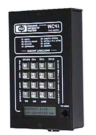
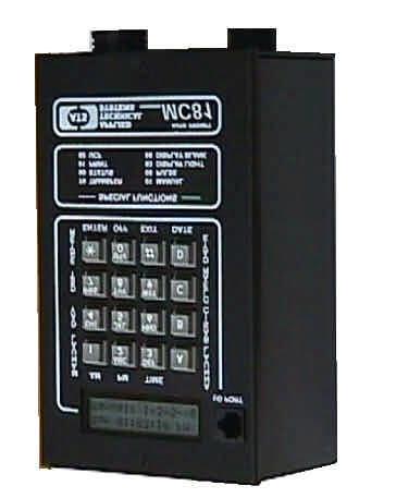
3 These are two basic versions of the AP41 / AP81 Series time switches. The AP41 is a four-circuit time switch, and the AP81 is an eight-circuit time switch. This manual will reference either unit as the "AP41 / AP81" or the "Time switch" in most cases. INTRODUCTION The AP41 / AP81 is a multiple output, calendar programmable solid state time switch. It is used for switching electric circuits according to a pre-set time and date program. The AP41 / AP81's AUTO PROMPTING, alpha-numeric display makes programming fast and simple. The outputs can be used to ring bells, to control audio/visual equipment or to control lighting, heating, ventilating, air conditioning and security systems with a variety of programming capabilities, ranging from a simple 7 day plan to a more complex plan utilizing its powerful, alternate annual programming features. Each has a compact wall mount enclosure. All output relays are available for timed events. The output relays are rated at 120 VAC, 15 amps resistive load. Selected outputs can be independently programmed for momentary operation such as required for ringing bells in schools, churches or industrial facilities. Limited options are available for the AP41/ AP81 time switches including 220 VAC power, 50 Hz power, etc. SPECIFICATIONS PROGRAMMING CAPABILITIES Auto Prompting Display - Provides display information to guide the operator during programming. From a cold start it will take the operator from setting time clear through setting the basic program steps. 200 Powerful Program Steps - The AP41 / AP81 has a default set up of 1 Basic, 7 day plan and 9 Alternate, 7 day plans that can be scheduled on an annual basis for a total of 10 plans, each having 20 program steps. If more than 20-program steps are needed, they can be programmed using a keyboard-entered function. Up to 100 steps per program can be programmed for a total of 2 plans. Each step can be programmed for all or any combination of the output relays for the specific day of the week, or for all 5 weekdays, or for both weekend days, or for everyday of the week. 20 Annual Plans - Each annual plan has a starting and ending date, and an associated Alternate Plan. This feature can be used to schedule any 1 of the 1 to 9 alternate, 7 day plans to be used by the AP41 / AP81. APPLIED TECHNICAL SYSTEMS PAGE 2
4 Programmable Daylight Savings Time Adjustment - The AP41 / AP81 can be programmed to automatically adjust its time for Daylight savings time changes according to U. S. law, even if the law changes. Automatic Leap Year Compensation. Manual Override - The output relays can be manually energized or de-energized from the keyboard. The manual override remains in effect until the next programmed step occurs. Pulsed Output - Selected outputs can be programmed individually or as a group to operate as momentary contacts, programmable from 1 to 9 seconds. Optional Program Transfer and Printout - The program and time from one AP41 / AP81 can be transferred to another AP Series Time switch or to a printer using the printer interface module. The optional transfer port is required. ELECTRICAL Power: Standard power required is from 95 VAC to 135 VAC, 60 HZ at 5 VA maximum. Clearly labeled terminal blocks are provided on the AP41 time switches. For the AP81, connector wiring harnesses (two 48 long multi-conductor cables) are provided for all field wiring. For optional powered units (220 VAC and 50 Hz), refer to the option addenda provided. Outputs: AP41 - Four relays (SPDT) rated at 15A, 120 VAC or 30 VDC resistive. AP81 - Eight relays (SPDT) rated at 5A, 120 VAC or 30 VDC resistive. Wiring AP41 - Clearly labeled Terminal Blocks on the PCB assembly, or an optional 16-pin connector with the mating, 48 inch wiring harness. AP81 - Connector wiring harnesses (two 48 long multi-conductor cables) are provided for all field wiring. POWER FAIL BACKUP Non-Volatile Memory keeps time and programs for extended power outages. Outputs and display are disabled during backup. The AP41 / AP81 resumes normal operation when power returns. APPLIED TECHNICAL SYSTEMS PAGE 3
5 ACCURACY Time Keeping - Synchronous with the AC power line. During a power failure it is quartz crystal controlled with an accuracy of +/-.005% throughout its full temperature range. Programmed Events - On/Off events are programmable with a one-minute resolution and occur at the zero second of that minute. Operating Temperature Range is from 0 to 50 degrees C PHYSICAL AP41: AP81: Black, painted aluminum enclosure - 4.8"W X 8"H X 1.8"D. Black, painted aluminum enclosure - 4.8"W X 8"H X 3.2"D. Mounting holes are provided in the enclosures for easy installation.. APPLIED TECHNICAL SYSTEMS PAGE 4


6 INSTALLATION AP41 / AP81 SERIES The AP41 / AP81 should be securely mounted to a suitable mounting panel or surface according to any local codes using the mounting holes provided. Be sure the equipment is properly grounded to the panel or the facilities ground connection. ELECTRICAL CONNECTIONS All wiring connections are made at the clearly marked terminal blocks located on the inside of the AP41 enclosure, or with the optional connector and wiring harness assembly. For AP41 s with the optional connector, and for the AP81 s refer to the Wiring Table below for wiring details. Otherwise, remove the top cover of the AP41 to gain access to the terminal block. AP41 shown with the top cover removed. Clearly, labeled terminal blocks are provided for all field wiring. AP81 connectors A and B are used with the 48 mating cable harnesses for all field wiring. APPLIED TECHNICAL SYSTEMS PAGE 5
7 WIRING TABLE CONNECTOR A (AP41 with connector option and AP81) PIN# COLOR FUNCTION 1 Black AC Line 2 White AC Neutral 3 Green Ground 4 Red Relay 1 C 5 Yellow Relay 1 NC 6 Violet Relay 2 C 7 White/Violet Relay 2 NO 8 NOT USED 9 Orange Relay 4 C 10 White/Yellow Relay 1 NO 11 Blue Relay 3 C 12 Gray Relay 3 NC 13 White/Blue Relay 3 NO 14 White/Brown Relay 4 NC 15 White/Orange Relay 4 NO 16 Brown Relay 2 NC CONNECTOR B (AP81 ONLY) OPTIONS 4 Red Relay 5 C 5 Yellow Relay 5 NC 6 Violet Relay 6 C 7 White/Violet Relay 6 NO 8 NOT USED 9 Orange Relay 8 C 10 White/Yellow Relay 5 NO 11 Blue Relay 7 C 12 Gray Relay 7 NC 13 White/Blue Relay 7 NO 14 White/Brown Relay 8 NC 15 White/Orange Relay 8 NO 16 Brown Relay 6 NC There are a variety of options available for the AP41 / AP81. For details on the installation and operation of the installed option, refer to the Addenda for those options at the back of this manual. APPLIED TECHNICAL SYSTEMS PAGE 6
8 FRONT PANEL DESCRIPTION DISPLAY, KEYBOARD AND LABELING ALPHANUMERIC DISPLAY - Used for displaying time, day, date, and output status, and for displaying information during programming or reviewing stored programs. KEYBOARD - Many keys serve multiple functions. Those keys are clearly labeled with their functions to the side and top of the key. They cannot be used incorrectly, as the display will AUTO PROMPT the user as to which key to press. AM / ON KEY [1] - Used for setting the time to AM when in the time set or programming modes and for entering the manual control mode. PM KEY [2] - Used for setting the time to PM when in the time set or programming modes. TIME KEY [3] - Used for entering the time set mode. ANNUAL KEY [A] - Used for entering the annual programming mode and for stepping through the stored annual plan for review. The annual plan contains the schedule for the alternate basic plans in calendar schedule form. BASIC KEY [B] - Used for entering the basic plan-programming mode and for stepping through the stored basic plans for review. The basic plans contain the daily timed events instructions. CLEAR KEY [C] - Used for clearing all annual plans and or basic plans. DATE KEY [D] - Used for entering the set date mode for entering date or reviewing the date. EXIT KEY [#] - Used for exiting any of the set time, set date or program modes. OFF KEY [0] - Used for setting the pulse to OFF when in the pulse programming mode. ENTER KEY [*] - Used for entering all commands or for stepping through any set time, set date or program data entry. DST KEY [7] - Used for entering the set Daylight Savings Time program mode. DAY KEY [4] - Used for setting the day in the set time and program modes. Also used for entering the set day mode. OPERATION FILLING OUT THE PROGRAM RECORD SHEET APPLIED TECHNICAL SYSTEMS PAGE 7
9 The AP Series Time Switches have extensive programming and control capability. In order to accurately document and enter your program the Program Record Sheet should be used. This sheet is self-explanatory. Copies are included at the back of this manual. AUTO PROMPT DISPLAY All AP Series Time Switches have a feature called Auto Prompt that guides the operator when programming the unit. For the most part the operator merely has to follow the display as the time switch advances through the program modes. On a cold start (from a discharged backup system) the time switch will advance through a sequence of all the necessary settings including the basic plans. You may exit this sequence if desired and enter the program manually from the time display. Entering a program from the Auto Prompt sequence is identical to entering one manually, except you have to enter each sequence manually. THE CURSOR On many of the display messages you will see a flashing square character called the cursor. The cursor indicates that you may now enter or change the data at that position of the display. ENTERING DATA As data is entered the time switch constantly checks for a valid entry. For example, you cannot enter 13 for a month when setting the date. After entering valid data to a position on the display, the cursor will advance to the next position. If you have tried to enter invalid data, the cursor will remain at the same position, indicating you must reenter the data. Simply re-enter the data on top of the existing data and press ENTER. Generally data is entered two digits at a time. EXITING THE AUTO PROMPT SEQUENCES Any time during a set time, date or programming mode, you may wish to exit the Auto Prompt sequence. Simply press the EXIT key. The time switch will advance to the time display. From this display you may enter any of the sequences manually. This manual will assume you have exited the Auto Prompt sequence after entering the time. If you had remained in the Auto Prompt sequence, all the sequences covered in the section on ENTERING, REVIEWING OR EDITING TIME AND PROGRAMS would automatically be invoked. APPLYING POWER Before power is applied be sure all installation and wiring is completed to all local codes. APPLIED TECHNICAL SYSTEMS PAGE 8
10 Upon first applying power the display will come up with a brief sign on message showing the model and version numbers: AP41 / AP81 TIME SWITCH Version 2.XX After a few seconds the first Auto Prompt message will appear. If this message does not appear, go to the ENTERING, REVIEWING OR EDITING TIME AND PROGRAMS section. UNIT POWER FAIL Press 3 key Simply press key [3]. The display will prompt with the set time display. Time? 00:00 AM Hrs. (HH), ENTER From this point forward you can exit the Auto Prompt sequence at any time, if desired, by pressing [EXIT]. However, the programming is simpler if you do not exit. You will notice that every numeric field is zero. On a cold start all memory is cleared in the time switch including time, date, and program steps. The cursor will be flashing in the hour s digits. The bottom line indicates that you need to enter 2 digits (HH) for hours. Simply enter the hours then press the [ENTER] key. Two digits are required for the hours. Example: 01 instead of 1. If you try to enter an invalid number for the hours, the cursor will remain flashing in the hour s digits. You must then re-enter the correct hours. If you have entered a valid number for the hours, the cursor will advance to the minute s digits. The bottom line again gives you additional information on how to enter the minutes. Now enter the desired two digits for the minutes and press [ENTER]. The cursor will advance to the AM position. Press the AM or PM key as desired and then press [ENTER]. Time keeping begins the instant you press [ENTER]. Time can be accurately set to the second by pressing the [ENTER] key at the instant you desire. After the time is set, the display will advance to the set date display. The time switch will continue to Auto Prompt all of the programming modes, except pulse, as data is entered. ENTERING, REVIEWING OR EDITING TIME AND PROGRAMS APPLIED TECHNICAL SYSTEMS PAGE 9
11 This section will explain how to change or review the existing time, date or programs previously stored, or to totally program the unit. If you have exited from the Auto Prompt sequence, it describes how to manually invoke each mode. If you did not exit the Auto Prompt sequence, ignore the first few instructions that explain how to invoke each mode. ENTERING, REVIEWING OR EDITING TIME [3] [ENTER] You must be in the time display before you can enter time. Press the EXIT key to be sure. The display should look similar to the following: Mon 01:18:00 PM Relays: OR Mon 01:18:00 PM Relays: Press the TIME key [3]. The display will respond with: Command? 03 Press ENTER Press [ENTER]. The display will respond with: Time? 12:34 AM Hrs. (HH), ENTER It may be showing the correct time or some other incorrect time previously stored. It may even be showing all 0's if you exited the auto prompt sequence. The cursor will be flashing in the hour s position. The bottom line will give you additional information on how to enter the data. Enter the desired two digit number for hours and press [ENTER]. If the hours are correct simply press [ENTER]. The cursor will move to the minute s position. Do not press [EXIT] part way through editing the time, date or any program steps unless you want to abort the editing. If you exit part way through, any changes made prior to the current position will be ignored. Enter the desired two digits for the minutes and press [ENTER]. The cursor will move to the AM/PM position. Before pressing [ENTER], you may wish to synchronize this time switch to some other reference clock. The instant you press [ENTER], the time keeping will begin. Therefore to synchronize with another reference clock, wait until it is ready to change to the desired time and press [ENTER] at that instant. ENTERING, REVIEWING OR EDITING THE DATE [D] [ENTER] APPLIED TECHNICAL SYSTEMS PAGE 10
12 You must be in the time display in order to enter the date. Press the DATE key [D]. The display will respond with: Command? 0D Press ENTER Press [ENTER]. The display will respond with: Date? Month (MM), ENTER It may be showing the correct date or some other date stored previously. It may even be showing all 0's if you exited from the auto prompt sequence. The cursor will be flashing in the month's position. The bottom line will give you additional information on how to enter the data. Enter the desired two digit number for the month and press [ENTER]. If the correct two digits are already there, simply press [ENTER]. The cursor will move to the day position. Enter the desired two digits for the day and press [ENTER]. The cursor will move to the year position. Enter the desired two digits for the year and press [ENTER]. The time switch will go back to the time display. To review your entry press the DATE key [D] and [ENTER]. The date display will appear. You can edit the date again if you wish or press [EXIT] to return to the time display. Remember that if you edit any part of the time, date or any program steps, you must not exit. Press [ENTER] until all positions of the display have been edited or you have accepted the default information in each display. ENTERING, REVIEWING OR EDITING THE DAY [4] [ENTER] You must be in the time display. Press the DAY key [4]. The display will respond with: Command? 04 Press ENTER Press [ENTER]. The display will respond with: Day? Sun DAY key, ENTER It may be showing the correct day or some other day stored previously. Press the DAY key [4] until the desired day is shown on the display and then press [ENTER]. The display will return to the time display. ENTERING, REVIEWING OR EDITING DAYLIGHT SAVINGS TIME [7] [ENTER] APPLIED TECHNICAL SYSTEMS PAGE 11
13 You must be in the time display. Press the DST key [7]. The display will respond with: Command? 07 Press ENTER Press [ENTER]. The display will respond with the default entries for the current U.S. law as follows: S DST M=04 SUN=1 F DST M=10 SUN=L The top line is for the Spring DST and the bottom line is for the Fall DST. The S indicates the Spring DST and the F indicates the Fall DST. The cursor will be flashing in the month position. Enter the desired two digits for the month you wish the Spring DST adjustment to be made (04 for current US law) and then press [ENTER]. The valid Spring months are 00, 03, 04, and 05. Enter 00 for the month if you wish to not use the automatic DST feature and the time switch will return to the time display. After a valid month is entered, the cursor will advance to the L in the Sunday position. Enter a 1 for the first Sunday (current US law), 2 for the second, 3 for the third, 4 for the fourth or L for the last Sunday. L is the same as key 5. The change will be made at 02:00 AM on the Sunday you choose. After the Spring DST data is entered, the cursor will advance to the Fall DST line. If you have entered a Spring DST, you must enter a Fall DST as well. Failure to do so will erase the Spring DST and then there will be no DST compensation. In the same manner as the Spring DST, enter the desired month and Sunday you wish the adjustment to be made. Current US law for Fall DST is the last Sunday in October. So enter 10 for the month and L (key 5) for the Sunday. The valid months for the Fall DST are 09, 10, and 11. The valid Sundays for the Fall DST are 1, 2, 3, 4 and L. L is the same as key 5. The change will be made at 02:00 AM on the Sunday you choose. ENTERING, REVIEWING OR EDITING THE BASIC PLAN PROGRAM [B] [ENTER] If the basic program was not entered during the cold start auto prompt sequence, it can be entered by entering the basic program mode. This mode allows the operator to program the daily timed events. Before entering your program be sure to write it out on a program record sheet. You may need to change the size of your basic program. See CHANGING THE BASIC PROGRAM SIZE section for more detail. Press BASIC [B]. The display will respond with: Command? 0B Press ENTER APPLIED TECHNICAL SYSTEMS PAGE 12
14 Press [ENTER]. The display will respond with: BASIC Plan #0 Step #00 The cursor will be flashing on the zero for plan #0. Plan #0 is the first of 10 Basic Plans, each of which contains a 7-day plan. Plan #0 is the main 7 day plan and plans 1 through 9 are alternate, 7 day plans that can be scheduled on an annual basis (more on this in the Annual Programming sections). Press [ENTER] to select plan #0. The cursor moves to the Step #00 position. Step #00 is the first step of 20 steps in plan #0. Press [ENTER] to select step #00 and the display will read as follows: #00 WDY 00:00 AM Relays: OR #01 WDY 00:00 AM Relays: If you have selected a secondary clock correction mode other than mode 0, be sure not to use relays 3 and 4. When the desired relay numbers appear on the bottom line, press [ENTER]. The first step 00 is now programmed. The #00 indicates that this is step 00 being displayed. The cursor will be flashing on the W of WDY. WDY stands for weekday. Program steps may be programmed for individual days, such as Mon or Tue, or for groups of days such as WDY for weekdays (Mon through Fri), EDY for everyday (Sun through Sat.) or WND for weekends (Sat & Sun). Press the DAY key to advance to the desired day or group of days. The display will update as you press the DAY key. Once the desired day or group of days is displayed, press [ENTER]. The display will advance to the hour s position. Enter the desired two digit hour at which this step is to be activated and press [ENTER]. The display will advance to the minute s position. Enter the desired two digits for minutes and press [ENTER]. The display will advance to the AM/PM position. Press the [AM] or [PM] key as desired and then [ENTER]. The display will advance to the first position after the word RELAY. Enter the number of the relays you wish to be energized by this program step. The relay numbers will appear on the bottom line as you press the appropriate number. Pressing the same number again will remove the relay number from the bottom line. This is useful when editing a program step. The following display shows an example of all relays being turned ON on Weekdays at 10:00 AM. #00 WDY 10:00 AM Relays: OR #00 WDY 10:00 AM Relays: APPLIED TECHNICAL SYSTEMS PAGE 13
15 When the desired relay numbers appear on the bottom line, press [ENTER]. The first step 00 is now programmed. The display will be prompting you for the next step 01. #01 WDY 00:00 AM Relays: OR #01 WDY 00:00 AM Relays: Enter the data for program step 01 the same as you did for step 00. Continue on until all your program steps are entered up to step 19 (the 20th step) or until you have entered the last step of your program. After entering your last step, press [EXIT] and the time switch will advance to the following display: BASIC Plan #1 Step # 00 The time switch is now prompting you to enter the first of 9 alternate plans, plan #1, if desired. Plans 1 through 9 are entered the same as plan 0. If you are not using alternate plans 1 through 9, or if you have just entered your last alternate plan, press [EXIT]. The time switch will advance to the main time display: CLEARING PROGRAM STEPS To clear a program step, press BASIC [B], then [ENTER]. BASIC Plan #0 Step # 00 The display will be prompting you for a plan #. Choose the basic plan in which the step you wish to clear is located, then press [ENTER]. The display will then be prompting you for a step #. Choose the # of the step you wish to clear, then press [ENTER]. The chosen step and its program contents will be displayed. The cursor will be on the S in Sun. Press [ENTER]. The cursor will go to the hour s position. Enter 00 for the hours to clear this specific step and press [ENTER]. The display will move to the next step allowing you to edit it as well. If you are finished press [EXIT]. The display will read: BASIC Plan #1 Step # 00 You can now choose another plan to edit or press [EXIT] again to return to the main time display. APPLIED TECHNICAL SYSTEMS PAGE 14
16 The display will return to the main time display. If you wish to erase all the program steps see the section on Clearing the Annual and Basic Programs. ENTERING, REVIEWING OR EDITING THE ANNUAL PLAN PROGRAM [A] [ENTER] The annual program allows the time switch to be programmed to select any 1 of the 9 alternate basic plans. This feature is useful for applications that require a different 7- day plan at different times into the future. There are 20 Annual Program Plans, each of which has a starting and ending date, and an associated, alternate Basic Plan. The selected alternate plan will begin at 12:00 AM on the start date and will end at 12:00 AM on the day after the end date. Basic Plan 0 takes over at the end of any Alternate plan. To enter the annual program mode press the ANNUAL [A] key. The display will respond with: Command? 0A Press ENTER Press [ENTER]. The display will respond with: ANNUAL #00 BASIC #1 The cursor will be prompting for an Annual Plan number. #00 is the first Annual Plan. Press [ENTER]. The cursor will then prompt for the desired Basic Plan to select with this Annual. Enter the desired Basic Plan number, then press [ENTER]. The display will read: Start? End? There may be a date already in the start date from a previous program. It is not necessary to erase this old date. You simply enter new data in each field. To erase an annual skip plan see sections Clearing the Annual and Basic Program and Clearing an Annual Plan. The cursor will be flashing in the month s position. Enter the desired two digits for the month at which this Annual Plan will start and press [ENTER]. The display will advance to the day s position. Enter the desired two digits for the day and press [ENTER]. The display will advance to the years position. Enter the desired two digits for the year and press enter. The cursor will advance to the end date line. Now you enter the end date in the same manner as the start date. If your Annual Plan is only for one day, you do not need to enter an end date. Just press [ENTER] to enter the 00 in the months and the display will advance to the next Annual Plan. ANNUAL #01 BASIC #1 APPLIED TECHNICAL SYSTEMS PAGE 15
17 Repeat the same procedure for Annual 01 as you did for Annual 00, or press [EXIT] to return to the time display. CLEARING AN ANNUAL PLAN If you need to clear an Annual Plan, press the ANNUAL [A] key and then [ENTER]. The display will respond with: ANNUAL #00 BASIC #1 Enter the desired Annual Plan number you wish to clear and press [ENTER] twice. The display will show the contents of that Annual Plan. Start? End? Enter 00 for the Start month and press [ENTER]. The plan will be cleared. There is no need to clear the end date once the start date has been cleared. If you wish to clear all the Annual Plans see the section on Clearing the Annual and Basic Programs. If you are programming the clock from a cold start, the annual and basic program steps will be cleared already. If you are re-programming a previously programmed clock you will need to erase any previous programs as they could conflict with your new program. To clear all program steps, press the CLEAR [C] key. The display will respond with: Command? 0C Press ENTER Press [ENTER]. The display will respond with: Clear buffers: A=ANNUAL B=BASIC You have the option now to clear either the annual or the basic program. To clear the annual, press [A], the same as the ANNUAL [A] key. The display will return to the time display. If it was the basic program you wished to clear, press the [B] or BASIC key instead of the [A]. Since there are 10 basic plans the time switch will give you the option to clear any 1 or all of the basic plans. See the following display: Press 0-9 or A for all sets At this point you enter the desired Basic Plan number you wish to clear or press [A] to clear all Basic Plans. APPLIED TECHNICAL SYSTEMS PAGE 16
18 If you wish to clear both the annual and basic programs, repeat the process a second time. Only one can be cleared at a time. SPECIAL FUNCTIONS MANUAL OPERATION OF THE OUTPUT RELAYS [1] [ENTER] The output relays can be manually controlled from the keyboard. Before doing this be sure it is okay to operate the loads connected to the time switch. Also be sure the unit is in the time display mode. To turn the output relays on press the manual [1] key. The display will respond with: Command? 01 Press ENTER Press [ENTER]. The display will read: Manual Control Relays: OR Manual Control Relays: Choose the desired relays that you would like to manually control by keying in the number of the respective relays. You will notice the numbers of the relays chosen will show up on the bottom line of the display. If a relay number is shown on the bottom line that you do not wish to turn on, you can remove it by keying that number in. You will notice that relay number is no longer on the display. Once the desired relays are showing on the display, press [ENTER]. The output relays chosen will be energized and the display will return to the time display. They will remain on until the next program step instructs them to turn off or on, or until they are manually operated again. ENTERING, REVIEWING OR EDITING THE PULSE [5] [ENTER] The pulse is normally set to zero for programming steady state ON and OFF events. A pulsed output may be desired for applications requiring a momentary output such as ringing school bells. You must be in the time display. Press key [5]. The display will respond with: Command? 05 Press [ENTER]. APPLIED TECHNICAL SYSTEMS PAGE 17
19 Press [ENTER]. The display will read: Pulse = OFF Relays: OR Pulse = OFF Relays: The cursor will be flashing on the "O" in OFF indicating that you may change the pulse. If pulsed output is not desired, press OFF [0] and then [ENTER]. The time switch will return to the main time display. If pulsed output is desired on 1 or more output relays, enter the number of seconds duration for this pulse from 1 to 9 seconds and press [ENTER]. Pulse = 3 seconds Relays: OR Pulse = 3 seconds Relays: The cursor will move to the first position after the word relay. Simply enter the number of the relay or relays to pulse. The display above shows an example of all 4 relays set to pulse for 3 seconds. MANUAL SELECTION OF ALTERNATE PLANS [2] [1] [ENTER] Alternate Plans can be selected by the keyboard in addition to being selected by the ANNUAL PROGRAM. To select an Alternate Plan type [2] [1] [ENTER]. The display will read: Select New Basic: 0 Enter the desired Basic Plan number, then press [ENTER]. The time switch will now run the program contained in the Basic Plan you have selected. The time switch will automatically go back to Basic Plan 0 after 12:00 AM. Also if any of the following changes are made, the time switch will go back to Basic Plan 0: Entering a new time. A power failure of any duration. Entering a new date. Modifying the Annual programs. Clearing the Annual programs. Use special function 90 to check status if necessary. SETTING THE MAXIMUM NUMBER OF STEPS PER PLAN [3] [1] [ENTER] APPLIED TECHNICAL SYSTEMS PAGE 18
20 The time switch has a default setup of 10 Basic Plans with 20 Program Steps each for a total of 200 steps. These plans are numbered Plan 0 through Plan 9. Plan 0 is the main Plan that will repeat itself every 7 days. Plans 1 through 9 are Alternate Plans that can be scheduled by the Annual Program, or they can be called up manually using the Manual Selection function as described above. For applications requiring more than 20 Steps per Plan, the time switch can be reconfigured to the desired number of Steps per Plan. Special function Command 31 is used to set the desired number of Steps required from 20 to 100 Steps per Plan. The number of Alternate Plans will automatically be adjusted to fit the maximum number of 200 Steps available. If you will need to change the maximum number of Steps per Plan, it should be done prior to entering your program. To set the number of Steps type [3] [1] [ENTER]. The display will read: Max. Step No: 19 (0-99), ENTER The cursor will be flashing on the maximum Step number prompting you to enter the desired maximum Step number. Since all Step numbers begin with 0, a maximum number of 19 represents 20 Steps. If your application requires 26 Steps, you can enter 25 for the maximum Step number, then press [ENTER]. The display will respond as follows: Max. Buffer No. = 6 (Press EXIT) Since the Basic Plans begin with Plan 0, this means there are a total of 7 Plans available. Each will have 26 Steps. To go back to the main time display, press [EXIT]. DISPLAY BLANKING [9] [8] [ENTER] The time switch display will automatically blank if the keyboard has not been used for 5 minutes or more. To override this feature press [9] [8] and [ENTER]. To change it back press [9] [8] and [ENTER] again. STATUS [9] [0] [ENTER] The time switch has a status check capability. Press [9] [0] then [ENTER] to check status. The display will read: Unit Status: T=N B=0 A=XX BK=N APPLIED TECHNICAL SYSTEMS PAGE 19
21 T status is for factory use only. It should always be "N". B status tells you which Basic Plan is in effect. A status tells you which Annual Plan is in effect. XX indicates no Annual Plan in use at this time. BK status tells you if the display blanking is on or off. FORCING A RESTART [7] [7] [ENTER] For training purposes or clearing all information from the time switch, you can do a cold start. Press [7] [7] [ENTER]. The display will show the UNIT POWER FAIL message. SOFTWARE VERSION [9] [9] [ENTER] To check the version of the software installed in your time switch press [9] [9] [ENTER]. The display will read: AP41 / AP81 TIME SWITCH Version 2.XX After 5 seconds the display will return to the time display. APPLIED TECHNICAL SYSTEMS PAGE 20
22 PROGRAMMING SUMMARY Read the sections on Programming Instructions before using the PROGRAMMING SUMMARY. SET TIME - Press TIME [3] key then [ENTER]. Enter the hours, press [ENTER]. Enter the minutes, press [ENTER]. Press [AM] or [PM], press [ENTER]. Timing begins the instant you press [ENTER] after entering the [AM] or [PM]. SET DATE - Press DATE [D] key then [ENTER]. Enter month, press [ENTER]. Enter day, press [ENTER]. Enter year, press [ENTER]. SET DAY - Press the DAY [4] key then [ENTER]. Press the DAY [4] key until desired day is displayed, then press [ENTER]. SET DST DATES - Press DST [7] key then [ENTER]. Enter month for Spring DST, press [ENTER]. Enter the desired Sunday for Spring DST, press [ENTER]. Enter month for Fall DST, press [ENTER]. Enter the desired Sunday for Fall DST, press [ENTER]. SETTING THE MAXIMUM NUMBER OF STEPS PER PLAN - Press [3] [1] then [ENTER]. Enter the desired number of steps per plan, up to 99, then press [ENTER]. Press [EXIT] after reviewing the display. ENTERING THE BASIC PLAN PROGRAM - Press the BASIC [B] key then [ENTER]. Enter the desired step number, press [ENTER]. Press the DAY [4] key until desired day or group of days is displayed, press [ENTER]. Press [AM] or [PM], press [ENTER]. Enter the desired relays to turn ON, press [ENTER]. The step is now programmed and ready for the next step. Repeat this process until entire program is entered then press [EXIT]. ENTERING THE ANNUAL PLAN PROGRAM - Press the ANNUAL [A] key then [ENTER]. Enter the desired Annual Plan number, press [ENTER]. Enter the start month, press [ENTER]. Enter the start day, press [ENTER]. Enter the start year, press [ENTER]. Enter the end month, press [ENTER]. Enter the end day, press [ENTER]. Enter the end year, press [ENTER]. The first skip plan is now programmed and ready for the next skip plan. Repeat this process until entire skip plan program is entered, then press [EXIT]. MANUAL SELECTION OF ALTERNATE PLANS - Press [2] [1] then [ENTER]. Select desired alternate plan (Basic Plan 1 to 9) then press [ENTER]. MANUAL OPERATION - Press MANUAL [1] then [ENTER]. Enter desired relays to manually control then press [ENTER]. The chosen relays will energize. APPLIED TECHNICAL SYSTEMS PAGE 21
23 CLEARING THE ANNUAL AND BASIC PROGRAMS - Press CLEAR [C] then [ENTER]. Press ANNUAL [A] to clear annual program or BASIC [B] to clear the basic program. Choose the desired sets buffer to clear. REVIEWING BASIC PLAN PROGRAM - Press BASIC [B] key then [ENTER]. Press BASIC [B] key again repeatedly to review each step. Press [EXIT] when done. REVIEWING THE ANNUAL PLAN PROGRAM - Press ANNUAL [A] key then [ENTER]. Press ANNUAL [A] key again repeatedly to review each skip plan. OPTIONS OPTIONAL PROGRAM TRANSFER [7] [8] [ENTER] The Program Transfer feature allows you to transfer time and program from one time switch to another. It is useful for applications where several units will have the same or a similar program, or where closely synchronized times are required from unit to unit. The optional transfer port and a transfer cable are required. To transfer, connect the transfer cable from the I/O port of one time switch to the other. Press [7] [8] and then [ENTER] on the master unit. The display will read: Connect Cable Then press ENTER If you have not already connected the cable, do so now then press [ENTER]. The displays will read: MASTER Sending Program * Please Wait * REMOTE Storing Program * Please Wait * After transfer is complete (about 10 seconds), both units will return to the time display. If transfer was unsuccessful the master unit will display the following: TRANSFER ERROR Press EXIT OPTIONAL PROGRAM PRINTOUT [9] [1] [ENTER] APPLIED TECHNICAL SYSTEMS PAGE 22
24 The program printout feature allows the time switch to dump its program contents to a standard parallel printer using the time switch Printer Interface Module. Program transfer option is required for the program printout feature. This works similar to the Transfer feature. To print from the time switch, connect the Printer Interface Adapter to your parallel printer and connect the transfer cable from time switch I/O port to the Printer Adapter. Enter [9] [1] then [ENTER]. The display will read: The display will read: Connect Printer, Then Press ENTER Printing Report, Please Wait... If the printout is unsuccessful the time switch will give a TRANSFER ERROR message. Check your cables and be sure the printer was on line. BASIC PLAN PROGRAM RECORD SHEET LOCATION DATE PULSED OUTPUT OFF SECONDS (1-9 SECONDS) APPLIED TECHNICAL SYSTEMS PAGE 23
25 RELAYS PULSED SECONDARY MODE SEE NOTE 1 BASIC PLAN # # OF STEPS / PLAN R E L A Y S STEP DAYS HH:MM A/P NOTE 1: When modes other than 0 are selected, relays 3 & 4 are dedicated to correction outputs. Make copies as required for Alternate Basic Plans. APPLIED TECHNICAL SYSTEMS PAGE 24
26 ANNUAL PLAN PROGRAM RECORD SHEET LOCATION DATE START DATE END DATE ANNUAL # BASIC # MM-DD-YY MM-DD-YY **** SPECIAL FUNCTIONS **** 01 MANUAL OPERATION 78 TRANSFER (OPTIONAL) 05 SET PULSE 90 UNIT STATUS 20 SET SECONDARY CLOCK MODE 91 PRINT (OPTIONAL) 21 SELECT ALTERNATE BASIC PLAN 31 SET NUMBER OF STEPS/PLAN 98 TOGGLE DISPLAY BLANKING 77 COLD BOOT (RESTART) 99 DISPLAY VERSION 93 TOGGLE LED DISPLAY BACKLIGHT (OPTIONAL) APPLIED TECHNICAL SYSTEMS PAGE 25
27 TECHNICAL SUPPORT For any questions concerning installation and operation of this product, contact our factory at: SERVICE POLICY PHONE (800) OR FAX (318) It is recommended that all service for this product be done by the factory or by a factory authorized service representative. Applied Technical Systems will provide ongoing service support in and out of warranty. Send your repairs to: APPLIED TECHNICAL SYSTEMS 849 KING PLACE SHREVEPORT, LA APPLIED TECHNICAL SYSTEMS WARRANTY POLICY ATS warrants its products to be free of defects in material and workmanship for a period of 24 months from the date of purchase. ATS will repair or replace any product returned to its authorized factory service center within the warranty period so long as there is no evidence that the product has been abused, misused, damaged by lightning, overloads of any kind or water, or altered in any way. Products returned for warranty must be returned with freight prepaid. ATS will pay normal freight charges to return the product to the customer. Special premium freight requested by the customer will be charged to the customer. ATS disclaims any warranties expressed or implied, including merchantability and/or fitness for a particular purpose. In no event shall ATS be held liable for incidental or consequential damages. APPLIED TECHNICAL SYSTEMS PAGE 26
28 This page left blank intentionally. APPLIED TECHNICAL SYSTEMS PAGE 27
29 This page left blank intentionally. APPLIED TECHNICAL SYSTEMS PAGE 28
MC4181LV SERIES MASTER CLOCKS
 FN:4181LV.DOC MC4181LV SERIES MASTER CLOCKS TABLE OF CONTENTS INTRODUCTION 2 SPECIFICATIONS 3 INSTALLATION 4 FRONT PANEL DESCRIPTION 4 OPERATION Filling out the Program Record Sheet and Auto-Prompt Display
AP21LV SERIES TIME SWITCHES version 2 TABLE OF CONTENTS
 AP21LV SERIES TIME SWITCHES version 2 TABLE OF CONTENTS INTRODUCTION.......................... Page 2 SPECIFICATIONS.......................... Page 3 INSTALLATION.......................... Page 4 DESCRIPTION..........................
AE21 SERIES DISPLAY CONTROL TERMINAL
 FN:AE21MAN1.DOC AE21 SERIES DISPLAY CONTROL TERMINAL DESCRIPTION The AE21 Series Display Control Terminal is used for implementing various display functions. It consists of a control terminal, the AE21,
AEXX SERIES MULTI-FUNCTION CLOCK/TIMERS
 FN:XXMFCT1.DOC AEXX SERIES MULTI-FUNCTION CLOCK/TIMERS AEXX SERIES MULTI-FUNCTION CLOCK/TIMERS REV 04/09/09 DESCRIPTION The AEXX Series of Multi-Function Clock/Timers are available with 1, 2.3, 4, 8, or
AEXX-349 SERIES REMOTE DISPLAYS
 FN:349MAN1.DOC AEXX-349 SERIES REMOTE DISPLAYS DESCRIPTION AEXX-349 Series Remote Displays are available with 1, 2.3, 4, 8, or 12 high digits, visible from 5 feet to 500 feet away. They are available in
CC186 AND CC186/2 STAND-ALONE OR SYSTEM CLOCK
 FN:CC186M2.DOC CC186 AND CC186/2 STAND-ALONE OR SYSTEM CLOCK DESCRIPTION The CC186 is a single sided clock with six, 1.8 inch high digits. The CC186/2 is a double sided clock with six, 1.8 inch high digits
AEXX-273 SERIES WIRELESS CONTROLLED PACE CLOCKS
 FN:273MAN1.DOC AEXX-273 SERIES WIRELESS CONTROLLED PACE CLOCKS DESCRIPTION AEXX-273 Series Wireless Controlled Pace Clocks are available in with 1", 2.3", 4", 8", or 12" high digits, visible from 5 feet
AE14-503J SERIES PRODUCTION DISPLAY SYSTEM
 FN:503JMAN2.DOC AE14-503J SERIES PRODUCTION DISPLAY SYSTEM DESCRIPTION The AE14-503J Series Production Display System is a stand-alone production pacing (Goal) and monitoring (Actual) display. It includes
Chronomax Time Switch
 Naztec Operations Manual For Chronomax Time Switch Version 1.x/2.x/3.x April 2003 Published by: Naztec, Inc. 820 Park Two Drive Sugar Land, Texas 77478 Phone: (281) 240-7233 Fax: (281) 240-7238 Copyright
AEQUERY DATA CAPTURE SOFTWARE
 FN:AEQUERY107M1.DOC AEQUERY DATA CAPTURE SOFTWARE DESCRIPTION AEQUERY is a data capture and control program for AE Series Production Monitor Displays. Systems with up to (32) AE44-503J, Dual Line Production
212iL Rev. 1.1
 212iL 1 International Electronics, Inc. 427 Turnpike Street Canton, Massachusetts 02021 212iL (illuminated Luxury) Keypad Single Unit Keypad- Control Installation Manual Features: 120 User Capability Illuminated
232iLM Keypad Installation and Programming Instructions
 232iLM Keypad Installation and Programming Instructions Note: This product is designed to be installed and serviced by security and lock industry professionals. Specifications Case Dimensions: 6 1 / 2
Model: EP210. Dual channel programmable controller. Installation Manual
 Model: EP210 Dual channel programmable controller Installation Manual Contents Introduction... 3 Product Compliance... 4 Safety Information... 4 Box content... 4 Features... 5 Installation... 5 Button
Secured Series: Hub Plus Kit Single Door Controller Package Installation Manual
 Secured Series: Hub Plus Kit Single Door Controller Package Installation Manual This package is designed to simplify the connections to our Secured Series Hub Plus Controller. This will translate into
Installation and Operation Manual. YMP/YBP Plus
 Installation and Manual YMP/YBP Plus Part # H003739 Rev. 4 March 2010 YMP/YBP Plus Installation Manual Safety Precautions All electrical power and signal wiring connected to the YMP/YBP PLUS Master, secondary
MAXIMA + Series ROTARY LEVEL CONTROL
 Price $5.00 MAXIMA + Series ROTARY LEVEL CONTROL OPERATING INSTRUCTIONS PLEASE READ CAREFULLY Division of Garner Industries 7201 North 98th Street Lincoln, NE 68507-9741 (402) 434-9102 925-0268 TABLE OF
SB-100 Employee Time Clock User Guide Icon Time Systems Automated Time and Attendance Solutions for Small Businesses
 P1503-01 P 150301 Rev 9.22.06 SB-100 Employee Time Clock User Guide Icon Time Systems Automated Time and Attendance Solutions for Small Businesses EPM DIGITAL SYSTEMS, INC., An Oregon Corporation ICON
Operating Manual. Master Clock KHU2101 COMPUTER MASTER CLOCK TIME 10 : 12 : 34 CLEAR
 Operating Manual 7 8 9 4 5 6 1 2 3 OMPUTER MASTER LOK TIME 10 : 12 : 34 HELP LEAR 0 ENTER KHU2101 Master lock KHU2100 Master lock System Time, Date & Daylight Saving Setting (Australia) A. NEW INSTALLATION
SP6R Level Controller Operation Manual
 SP6R Level Controller Operation Manual www.sjerhombus.com SP6R LEVEL CONTROLLER INTRODUCTION SJE-Rhombus, an industry leader in water and wastewater pump controls, introduces the SP6R Level Controller.
SK-1011-SQ Digital Access Keypad with 5A Relay Output
 User Operation for the SK--SQ. Using the User Codes: A. User codes operate the door (4-8 digits long). Press u u u u B. The key must also be pressed if the keypad is in manual-entry mode. Press u u u u
7 Day Digital Programmer 2 Channel Surface Mount
 7 Day Digital Programmer 2 Channel Surface Mount Model: TRT036N Installation & Operating Instructions 1. General Information These instructions should be read carefully and retained for further reference
2000 Series e/em Style Keypad Installation and Programming Manual
 2000 Series e/em Style Keypad Installation and Programming Manual Document Number: 6054022 Revision: 0 Date: 12/21/06 Table of Contents Table of Contents Section 1: Introduction... 6 1 Product Description...6
User/Installation Manual
 User/Installation Manual ADVANTAGE DKLP MODEL 19-100(i) Your Partner in Access Control www.americanaccess.com AAS 2Year Limited Warranty What item(s) this warranty applies to: American Access Systems DKLP
MAXIMA + Series ROTARY LEVEL CONTROL
 Price $5.00 MAXIMA + Series ROTARY LEVEL CONTROL OPERATING INSTRUCTIONS PLEASE READ CAREFULLY Division of Garner Industries 7201 North 98th Street Lincoln, NE 68507-9741 (402) 434-9102 925-0268 Rev. A
PMDX-105. I/O Option Riser Board User s Manual. Document Revision: 1.1 Date: 7 September 2004 PCB Revision: PCB-443A
 PMDX-105 I/O Option Riser Board User s Manual Date: 7 September 2004 PMDX Web: http://www.pmdx.com 7432 Alban Station Blvd., A105 Phone: +1 (703) 912-4991 Springfield, VA 22150-2321 USA FAX: +1 (703) 912-5849
SIMREX Corporation Your Trusted Wireless Solution Provider
 SIMSYNC Instruction Manual Traffic Controller Time/Date Synchronization/Coordination System Firmware Release 2.5h SIMREX MAN.SIMSYNC, Rev 13.0 FEBRUARY 2008 Your Trusted Wireless Solution Provider www.simrex.com
7 Day Digital Programmer 1 Channel Surface Mount
 7 Day Digital Programmer 1 Channel Surface Mount Model: TRT034N Installation & Operating Instructions 1. General Information These instructions should be read carefully and retained for further reference
Elapsed Timer Control Panel
 Installation Manual V6.2 Elapsed Timer Control Panel Current as of August 2017 The Sapling Company, Inc. Elapsed Timer Control Panel Table of Contents Table of Contents 2 Important Safety Instructions
SA-027WQ. Manual. 7-Day Timer. Lighting Systems Access Controls Security Systems Environmental Controls. Automate the following:
 SA-027WQ 7-Day Timer Manual Automate the following: Lighting Systems Access Controls Security Systems Environmental Controls 12~24 VAC/VDC Program up to 60 flexible events Holiday function (up to 99 days)
MAXIMA+ Series Rotary Level Indicator
 MAXIMA+ Series Rotary Level Indicator BinMaster: Division of Garner Industries 7201 N. 98th St., Lincoln, NE 68507 402-434-9102 email: info@binmaster.com www.binmaster.com OPERATING INSTRUCTIONS PLEASE
ODOT ITB Section 4: Flashers, Timers, & Software Systems Item 4-1
 ODOT ITB 063-17 Item 4-1 DATA SHEET SSF-86-3 ODOT ITB 063-17 Item 4-1 Solid State Flasher: Description: The PDC model SSF-86 solid state flasher is a dual circuit flasher designed for the Traffic Control
Installation & Operation
 LED Readout Installation & Operation WARRANTY Accurate Technology, Inc. warrants the ProScale Systems against defective parts and workmanship for 1 year commencing from the date of original purchase. Upon
HN1000/HN2000 Product Manual
 HN1000/HN2000 Product Manual TABLE OF CONTENTS 1.0 Introduction...1 2.0 Mounting the HN1000/HN2000... 2 3.0 Setting Up Your Optional upunch Account... 4 3.1 Creating Your Account...4 3.2 Adding Departments
Plus-X AC-8. User Guide
 Plus-X AC-8 User Guide Table of Contents Introduction... 1 Network Requirements... 1 Setup and Configuration... 1 Operation... 5 Uploading Firmware... 7 Getting Help... 7 Warranty... 7 Appendix A: Specifications...
ENFORCER SK-1131-SQ. Digital Access Keypad with 5A Relay Output MANUAL. Digital Access Keypad Manual. Also available from SECO-LARM: Outdoor Keypads
 User Operation for the SK--SQ Note: n n n nindicates. Using the User Codes: A. User codes operate the door (4-8 digits long). the inhibit code. Note: u u u uindicates Press u u u u the user code. B. The
Carefree-Security. Installation and programming instructions 1050A. Owner s Manual
 Carefree-Security Heavy Duty Commercial - Industrial Fully Sealed Digital Access Keypad Specially Designed for Gate Operators, Overhead Doors, Specialty Doors & Electric Door Locking Devices SINGLE OR
P4472 Save A Watt HD Operation Manual
 P4472 Save A Watt HD Operation Manual Thank you for purchasing the P4472 Save A Watt HD. This operating manual will provide an overview of the product, safety instructions, a quick guide to operation,
Model P4470 Save A Watt Operation Manual
 Model P4470 Save A Watt Operation Manual Thank you for purchasing the P4470 Save A Watt. This operating manual will provide an overview of the product, safety instructions, a quick guide to operation,
Delta 40. This user guide will ensure you obtain the best use of your answer machine. USER GUIDE
 Delta 40 Thank you for choosing a Delta 40 Answer Machine. You have selected a carefully designed answer machine that incorporates the latest technology giving 40 minutes total recording time, a unique
SK-1011-SDQ Access Control Keypad. Manual
 SK-1011-SDQ Access Control Keypad Manual Quick Installation Guide: This page is for installers looking to do a basic installation and programming of the keypad. For more in-depth installation and programming
Installation, Testing, and Operating Procedures 30 AMP PORTABLE AND PERMANENT SERIES GFCI SINGLE and MULTIPHASE
 IMPORTANT! Please read all the information on this sheet. SAVE THESE INSTRUCTIONS! NOTICE BEFORE USING READ INSTRUCTIONS COMPLETELY. TO BE INSTALLED BY A QUALIFIED ELECTRICIAN IN ACCORDANCE WITH NATIONAL
MODEL No. SW1X8 RS422 SWITCHER
 12843 Foothill Blvd. Suite C Sylmar, California 91342 V: 818.898.3380 F: 818.898.3360 sales@dnfcontrols.com MODEL No. SW1X8 RS422 SWITCHER User Manual TABLE OF CONTENTS I. REVISION HISTORY... 2 II. INTRODUCTION...
TORK DG100 / DG120 DIGITAL TIME SWITCH SEVEN DAY
 TORK DG100 / DG120 DIGITAL TIME SWITCH SEVEN DAY READ INSTRUCTIONS CAREFULLY BEFORE SETTING UNIT FEATURES Single channel controller 7 day scheduling Special day scheduling 32 set points Battery back-up
TSD-SEQ6 Sequencer Controller
 Owner s Manual 1 AtlasSound.com Owner s Manual Description The Atlas Sound features 6 outputs that are configurable individually to be either a 24VDC output or Hard Switch Contact Closure (CC). There are
icp installation guide
 The Information Control Point (icp) is the latest SmartFarm Technology by Inc. The icp is the ultimate on-farm data-management tool. The icp has all the power of a basic personal computer, but instead
Manual. NanoTron Dual Timer. Installation Maintenance Repair Manual
 Manual NanoTron Dual Timer Installation Maintenance Repair Manual Advantage Controls P.O. Box 1472 Muskogee, OK 74402 Phone: 800-743-7431 Fax: 888-686-6212 www.advantagecontrols.com email: support@advantagecontrols.com
AMERICAN ACCESS SYSTEMS, INC.
 AMERICAN ACCESS SYSTEMS, INC. American Access Systems, Inc. 7079 South Jordan Road #6 Centennial, CO 80112 TECH: (303) 799-9757 SALES: 800-541-5677 FAX: (303) 799-9756 PROX 2000 II INSTALLATION & PROGRAMMING
USER GUIDE. Version 1J 9/20/00 INTELLIGENT LIGHTING CONTROLS, INC.
 USER GUIDE Version 1J 9/20/00 INTELLIGENT LIGHTING CONTROLS, INC. 5229 Edina Industrial Boulevard Minneapolis. Minnesota 55439 Phone 952 829 1900 FAX 952 829 1901 1-800-922-8004 Overview The QUANTA Elite
Digital Lighting Systems, Inc.
 Digital Lighting Systems, Inc. Four Channel Dry Contacts Relays Switch Pack DMX512 compatible USER'S MANUAL -UM User's Manual - Page 1 GENERAL DESCRIPTION The is a 4-channel DMX-512 compatible electro-mechanical
User/Installation Manual
 User/Installation Manual PROX 2000 II MODEL 23-206(i) Your PARTNER in Access Control www.americanaccess.com AAS 2Year Limited Warranty What item(s) this warranty applies to: American Access Systems PROX
E101B 4/3/07 9:52 PM Page 1 E201B 10 MLI-210(REVA)
") E101B 4/3/07 9:52 PM Page 1 E201B 10 MLI-210(REVA) E101B 4/3/07 9:52 PM Page 9 4.1 SETTING HOURS AND MINUTES Press HOUR and MIN to set desired time. Press EVENT to set desired event (ON/) and then press
E101B 4/3/07 9:52 PM Page 1 E201B 10 MLI-210(REVA) E101B 4/3/07 9:52 PM Page 9 4.1 SETTING HOURS AND MINUTES Press HOUR and MIN to set desired time. Press EVENT to set desired event (ON/) and then press
9212i INSTALLATION. Stand-Alone Keypad. Instructions
 INSTALLATION 9212i Stand-Alone Keypad Instructions Features: 4 Independent Outputs 4 Independent Timers All Outputs Assignable by Code On board 5 Amp Form C Relay 120 Users Remote Triggering Input Keypad
Plus-X 300. Installation and Operation Manual
 Plus-X 300 Installation and Operation Manual Table of Contents Introduction... 1 Compatibility... 1 Installation... 1 Configuration... 2 Operation... 5 Getting Help... 6 Warranty... 6 Appendix A: Specifications...
Pulse LED Instruction Guide
 PARTS LIST Light Fixture Aquarium Frame Mounts Instruction Guide WARNING: To guard against injury, basic precautions should be observed, including the following: A) READ AND FOLLOW ALL SAFETY INSTRUCTIONS.
PRO REMOTE 25 CAPACITANCE PROBE OPERATING INSTRUCTIONS READ THOROUGHLY BEFORE INSTALLING EQUIPMENT Jamieson Equipmen toll free 800
 PRO REMOTE 25 CAPACITANCE PROBE OPERATING INSTRUCTIONS READ THOROUGHLY BEFORE INSTALLING EQUIPMENT TABLE OF CONTENTS GENERAL SPECIFICATIONS...3 1.0 INTRODUCTION...4 2.0 APPLICATIONS...4 3.0 INSTALLATION...4
Card Nest Universal 12 position card nest for all K-AB cards above and all other K-AB cards.
 Installation And Operation BASIC A/B SWITCHES K-AB-D25 K-AB-M34 SCOPE OF THIS DOCUMENT This document covers the following models: K-AB-D25 K-AB-D25-R K-AB-M34 K-AB-M34-R For the purposes of clarity, all
PagePac PAGEPAC PLUS ZONE EXPANSION UNIT V
 PagePac Issue 3 by PAGEPAC PLUS ZONE EXPANSION UNIT V-5335100 INTRODUCTION The Zone Expansion Unit (ZEU) provides up to 16 zones of audio output (including talkback), contact closure outputs or inputs.
AMERICAN ACCESS SYSTEMS, INC.
 AMERICAN ACCESS SYSTEMS, INC. PROX 2000 II INSTALLATION & PROGRAMMING INSTRUCTIONS MODELS: 23-206 AAS 2-Year Limited Warranty What item(s) this warranty applies to: American Access Systems "PROX 2000 II
TMR-08 Weekly Switch Timer
 Table of Contents TMR-08 Weekly Switch Timer 1. Package Contents... 1 2. Panel Descriptions... 2 3. Introduction... 4 4. Main Screen... 6 5. Set Date & Time... 7 6. Set No. of Programs... 8 7. Set Program
User's Guide. 1/16 th DIN ph Controller. Model 48PH2. Introduction
 User's Guide 1/16 th DIN ph Controller Model 48PH2 Introduction Thank you for selecting the Extech Model 48PH2 controller. This 1/16 th DIN-size controller offers dual display, high resolution measurements,
RESIDENTIAL OPERATOR MOTOR CONTROL BOARD REPLACEMENT INSTRUCTIONS
 READ THIS MANUAL CAREFULLY BEFORE BEGINNING INSTALLATION RESIDENTIAL OPERATOR MOTOR CONTROL BOARD REPLACEMENT INSTRUCTIONS PRODUCT FEATURES MODELS: IIA SPRINT 310/510/710 200/250 2000 SERIES 3000 SERIES
PRO I Series CAPACITANCE PROBE
 Price $5.00 PRO I Series CAPACITANCE PROBE OPERATING INSTRUCTIONS PLEASE READ CAREFULLY TABLE OF CONTENTS GENERAL SPECIFICATIONS... 3 1.0 INTRODUCTION... 4 2.0 APPLICATIONS... 4 3.0 INSTALLATION... 4 3.1
Digital Lighting Systems, Inc. PD216. Two Channel Dimmer and Switch Packs PROTOCOL USER'S MANUAL. PD216-UM Rev. E - 02/03
 Digital Lighting Systems, Inc. PD26 Two Channel Dimmer and Switch Packs PROTOCOL PD26 S2 S USER'S MANUAL PD26-UM Rev. E - 02/03 Digital Lighting Systems PD26 User's Manual - Page GENERAL DESCRIPTION The
VMI. Technical Documentation. 600 Industrial Drive, New Bern, N.C (tel / fax /
 VMI E-Series Virtual Mixer Interface Technical Documentation 600 Industrial Drive, New Bern, N.C. 28562 (tel 252-638-7000 / fax 252-637-1285 / email@wheatstone.com ) VMI E-Series Virtual Mixer Interface
E101B SINGLE 3/2011 Page 1
 E101B SINGLE 3/2011 Page 1 MLI-203(REVA) E101B SINGLE 3/2011 Page 2 TABLE OF CONTENTS Section Page Installation Instructions and Capabilities.................... 1 Key Functions.................... 2 1.0
The Analyst. RS422/RS232 Tester. (Standard Model) User Manual
 User Manual") 12843 Foothill Blvd., Suite D Sylmar, CA 91342 818 898 3380 voice 818 898 3360 fax www.dnfcontrolscom The Analyst RS422/RS232 Tester (Standard Model) User Manual Manual Revision 102506 Table of Contents
12843 Foothill Blvd., Suite D Sylmar, CA 91342 818 898 3380 voice 818 898 3360 fax www.dnfcontrolscom The Analyst RS422/RS232 Tester (Standard Model) User Manual Manual Revision 102506 Table of Contents
Dim levels for each system output may be controlled by any of the following methods:
 Applied Electronics Bravo Series Dimming System Rack-Mount Architectural l SA12/2400A and l SA12/2400E Setup and Operation Instructions 1.0 Scope This document details the setup and operation requirements
Vibra LITE 7 Mini QUICK START GUIDE:
 Vibra LITE 7 Mini QUICK START GUIDE: Note: to SET any function, the Digit(s) that you want to set MUST BE FLASHING. TIME & CALENDAR: Set hour, minutes, seconds & date. Press the MODE button to rotate to
INSTRUCTION and OPERATIONS MANUAL. for
 INSTRUCTION and OPERATIONS MANUAL for CAB SIGNAL MASTER MODEL NUMBER 15100-00 CAUTION Be sure to read and become thoroughly familiar with the entire contents of this manual before attempting to operate
Digital Room Thermostat
 Salus RT500 Manual 002:89 23/11/10 11:06 Page 1 Digital Room Thermostat Instruction Manual Model No RT500 2 Salus RT500 Manual 002:89 23/11/10 11:06 Page 2 PRODUCT COMPLIANCE This product complies with
Indoor/Outdoor Proximity Reader and Keypad with 10cm (4in) Read Range
 Read Range") Indoor/Outdoor Proximity Reader and Keypad with 10cm (4in) Read Range Stand alone CR-R885-SB Installation and Operating Instructions V1.1 TABLE OF CONTENTS Installation... 2 Mounting and Wiring... 2 Mounting
Indoor/Outdoor Proximity Reader and Keypad with 10cm (4in) Read Range Stand alone CR-R885-SB Installation and Operating Instructions V1.1 TABLE OF CONTENTS Installation... 2 Mounting and Wiring... 2 Mounting
20W Tungsten-Halogen Light Source. Operation Manual
 20W Tungsten-Halogen Light Source - ASB-W-020 - Operation Manual Important Safety Notices 1. Never look directly into the light beam, including through the cooling fan while light is on, as this can cause
4300 WINDFERN RD #100 - HOUSTON TX VOICE (713) FAX (713) web: IMPORTANT!!!
 FAX (713) web: IMPORTANT!!!") 4300 WINDFERN RD #100 - HOUSTON TX 77041-8943 VOICE (713) 973-6905 - FAX (713) 973-9352 web: www.twrlighting.com IMPORTANT!!! PLEASE TAKE THE TIME TO FILL OUT THIS FORM COMPLETELY. FILE IT IN A SAFE PLACE.
4300 WINDFERN RD #100 - HOUSTON TX 77041-8943 VOICE (713) 973-6905 - FAX (713) 973-9352 web: www.twrlighting.com IMPORTANT!!! PLEASE TAKE THE TIME TO FILL OUT THIS FORM COMPLETELY. FILE IT IN A SAFE PLACE.
SVP110 SURGE VOLTAGE PROTECTOR INSTRUCTION MANUAL
 SVP110 SURGE VOLTAGE PROTECTOR INSTRUCTION MANUAL REVISION: 01/03/03 COPYRIGHT (c) 1995-2000 CAMPBELL SCIENTIFIC, INC. This is a blank page. WARRANTY AND ASSISTANCE The SVP110 SURGE VOLTAGE PROTECTOR is
Krontek KT160 Digital Clock
 Krontek KT160 Digital Clock Operators Manual Krontek KT160 Rev 4.12a 1 SETUP OVERVIEW All settings are via three pushbutton keys on the rear of the clock: The SYSTEM key, the TIME key and the ADJUST key.
Delta 40. This user guide will ensure you obtain the best use of your answer machine. USER GUIDE
 Delta 40 Thank you for choosing a Delta 40 Answer Machine. You have selected a carefully designed answer machine that incorporates the latest technology giving 40 minutes total recording time, a unique
E101B SINGLE 7/22/07 10:02 PM Page 1
 E101B SINGLE 7/22/07 10:02 PM Page 1 E101B SINGLE 7/22/07 10:02 PM Page 2 TABLE OF CONTENTS Section Page Installation Instructions and Capabilities.................... 1 Key Functions....................
DOLXFD1000B. Waterproof Access Control/Reader
 DOLXFD1000B Waterproof Access Control/Reader INTRODUCTION The DOLXFD1000B is a single- entry multi-function Access Controller with integrated keypad and card reader. It is designed and manufactured to
4300 WINDFERN RD #100 HOUSTON TX VOICE (713) FAX (713) web: IMPORTANT!!!
 FAX (713) web: IMPORTANT!!!") 4300 WINDFERN RD #100 HOUSTON TX 77041-8943 VOICE (713) 973-6905 FAX (713) 973-9352 web: www.twrlighting.com IMPORTANT!!! PLEASE TAKE THE TIME TO FILL OUT THIS FORM COMPLETELY. FILE IT IN A SAFE PLACE.
4300 WINDFERN RD #100 HOUSTON TX 77041-8943 VOICE (713) 973-6905 FAX (713) 973-9352 web: www.twrlighting.com IMPORTANT!!! PLEASE TAKE THE TIME TO FILL OUT THIS FORM COMPLETELY. FILE IT IN A SAFE PLACE.
Plus-X 600. Installation and Operation Manual
 Plus-X 600 Installation and Operation Manual Table of Contents Introduction... 1 Compatibility... 1 Unpacking... 1 Front Panel Indicators... 2 Hardware Configuration... 2 Installation... 4 Software Configuration...
MODEL NC400 MULTI-FUNCTION TOUCH-TONE DECODER INSTRUCTION MANUAL
 15385 Carrie Drive Grass Valley, CA 95959 Office: (530) 477-8400 Tech. Support: (530) 477-8402 FAX: (530) 477-8403 Sales: (800) 874-8663 Email: tech@ norcommcorp.com Web: www.norcommcorp.com MODEL NC400
INSTALLATION INSTRUCTIONS Model 930 EntryCheck
 SECURITY DOOR CONTROLS 3580 Willow Lane, Westlake Village, CA 91361-4921 (805) 494-0622 Fax: (805) 494-8861 www.sdcsecurity.com E-mail: service@sdcsecurity.com INSTALLATION INSTRUCTIONS Model 930 EntryCheck
VCMDM MODEM INSTALLATION INSTRUCTIONS
 Issue 1 www.class-connection.com VCMDM MODEM INSTALLATION INSTRUCTIONS The VCMDM Modem Package allows the user to program the Class Connection TM or VC-24 System from an off-site location. This document
Pegasus HC Lighting Control Panel
 Overview The drives up to 32 relays, each rated 20 amps, with an integrated time clock and photocell input. Users can manually switch outputs on or off from a remote pushbutton controller, or create time
V-9939B MICROPHONE ADAPTER
 Issue 10 INTRODUCTION These instructions provide identification, installation, connection, operation and maintenance information for the Microphone Adapter. The is a Microphone Adapter designed to be used
Kodiak Mobile INTELLIGENT DOCKING STATION USERS MANUAL PART NUMBER: PANASONIC CF53 TOUGHBOOK COMPATIBLE AN ISO 9001:2008 CERTIFIED COMPANY
 CUSTOMER SERVICE If you have any questions or require additional information please contact Customer Service at 877-455-6886, Monday though Friday, 8:00am - 5:00pm CST. TECHNICAL SUPPORT Kodiak Mobile
Owner s Manual. TSD-DCPDV DC Power Distribution with Fixed & Variable Outputs. TSD-DCPDV DC Power Distribution. AtlasSound.com
 Owner s Manual with Fixed & Variable Outputs 1 AtlasSound.com Owner s Manual Description The Atlas Sound Variable Block is designed to reduce cost and wiring clutter in installations where multiple DC
OPERATING INSTRUCTIONS
 TM CarSense 303-L OPERATING INSTRUCTIONS LOGIC INTERFACE 4564 Johnston Parkway, Cleveland, Ohio 44128 P. 800 426 9912 F. 216 518 9884 Sales Inquiries: salessupport@emxinc.com Technical Support: technical@emxinc.com
Digital Lighting Systems, Inc. PD405-DMX. Four Channel Dimmer and Switch Packs. DMX512 compatible. PD405-DMX-24DC DMX512 4 x 5 Amps Dimmer Pack
 Digital Lighting Systems, Inc. PD405DMX Four Channel Dimmer and Switch Packs DMX52 compatible PD405DMX24DC DMX52 4 x 5 Amps Dimmer Pack C UL US LISTED www.digitallighting.com Digital Lighting Systems,
LevCon. Liquid Level Indicator / Controller DIAL-SJE ( )
") LevCon Liquid Level Indicator / Controller 1-888-DIAL-SJE (1-888-342-5753) www.sjerhombus.com LEVCON CONTROLLER INTRODUCTION The LevCon set point level controller is a self-contained microprocessor controlled
LevCon Liquid Level Indicator / Controller 1-888-DIAL-SJE (1-888-342-5753) www.sjerhombus.com LEVCON CONTROLLER INTRODUCTION The LevCon set point level controller is a self-contained microprocessor controlled
poly-planar Marine Audio Systems
 ME60BT Bluetooth Amplifier 1 Introduction: The ME60BT is a four channel, 120 Watts RMS Bluetooth wireless audio amplifier, capable of delivering up to 30W RMS per channel. It has a compact, water resistant
NT1-220 Rack. Installation Instructions. Specifications. Contents of Shipping Box. Important Safety Instructions. NT1-220 Rack
 The NT1-220 Rack is designed to be used in conjunction with Tone Commander NT1U-220TC ISDN Network Terminations. A maximum of twelve NT1 units can be used in each rack. NT1-220 Rack Installation Instructions
TS InteliSwitch Digital Time Switch 24VDC/VAC
 SPECIFICATIONS InteliSwitch Digital Time Switch 24VDC/VAC Voltages... 24VAC, 24VDC, VAC Half Rectified Current Consumption............................ Max. 15mA DC........................................
STATUS Shiloh Road Alpharetta, Georgia (770) FAX (770) Toll Free
 FAX (770) Toll Free") Instruction Manual Model 1582-45L Data Switch September 2010, Rev A REMOTE LOCAL SWITCH STATUS SELECT REMOTE LOCAL LOCAL SELECT CHANNEL SELECT POWER MODEL 1582 SWITCH CROSS TECHNOLOGIES, INC. Data, drawings,
Instruction Manual Model 1582-45L Data Switch September 2010, Rev A REMOTE LOCAL SWITCH STATUS SELECT REMOTE LOCAL LOCAL SELECT CHANNEL SELECT POWER MODEL 1582 SWITCH CROSS TECHNOLOGIES, INC. Data, drawings,
NT1B-300 Rack Installation Instructions
 The NT1B-300 Rack houses 24 Tone Commander NT1B-300TC ISDN Network Terminations in a 19 rack, 23 rack, or wall mount configuration. The rack is also compatible with Lucent NT1B-300 NT1s. The rack supplies
SKE Series. 12-Pad. Installation & Instruction Manual. Essex Electronics, Inc KEY-LESS fax keyless.
 SKE Series 12-Pad Installation & Instruction Manual Essex Electronics, Inc. 805.684.7601 800.KEY-LESS fax 805.684.0232 keyless.com SKE Series 12-Pad Self-Contained Keyless Entry System With Relay All rights
Digital Lighting Systems, Inc.
 , Inc. PD402-DMX Four Channel Dimmer and Switch Packs 4 x 2.5 Amps @ 6VDC to 24 VDC DMX52 compatible DMX52 4 x 2.5 Amps Dimmer Pack C UL US LISTED Digital Lighting Systems, Inc. USER'S MANUAL User's Manual
INSTRUCTION MANUAL EW101B EW103B EW120B DIGITIAL TIME SWITCH USA MLI-204 (C)
") INSTRUCTION MANUAL EW101B EW103B EW120B DIGITIAL TIME SWITCH 888.500.4598 USA www.nsiindustries.com MLI-204 (C) TABLE OF CONTENTS Section Page Installation Instructions and Capabilities...1 Key Functions...2
INSTRUCTION MANUAL EW101B EW103B EW120B DIGITIAL TIME SWITCH 888.500.4598 USA www.nsiindustries.com MLI-204 (C) TABLE OF CONTENTS Section Page Installation Instructions and Capabilities...1 Key Functions...2
PIECAL 322 Automated Thermocouple Calibrator Operating Instructions. Product Description. Practical Instrument Electronics
 PIECAL 322 Automated Thermocouple Calibrator Operating Instructions Product Description Easy to use With the PIECAL 322-1 you can check & calibrate all your thermocouple instruments and measure thermocouple
R & D SPECIALTIES SERIES 100 RO CONTROLLER USERS MANUAL. 2004, by R & D Specialties, Inc. All Rights Reserved.
 R & D SPECIALTIES 2004, by R & D Specialties, Inc. All Rights Reserved. No part of this document may be copied or reproduced in any form or by any means without the prior written permission of R & D Specialties.