D i g i g r a m. VX222v2. Professional Stereo Sound Card. User s manual
|
|
|
- Archibald Reynolds
- 5 years ago
- Views:
Transcription

1 Professional Stereo Sound Card User s manual
4 76 52 55 01 Fax: +33 (0) 4 76 52 53 07 E-mail: info@digigram.com Digigram Inc.")
2 For technical support, please contact your local distributor. list available at 2 Digigram S.A. Parc de Pré Milliet, Montbonnot - FRANCE Tel: +33 (0) Fax: +33 (0) info@digigram.com Digigram Inc Wilson Boulevard, Suite 1004, Arlington, VA USA Tel: Fax: input@digigram.com Digigram Asia Pte Ltd. 350 Orchard Road - #19-07 Shaw House Singapore Singapore Tel: Fax: info_asia@digigram.com
3 Table of Contents User s Manual INFORMATION FOR THE USER...5 IMPORTANT NOTICE...5 CONTENTS OF THIS PACKAGE...6 FEATURES...6 Main hardware features...6 HARDWARE REQUIREMENTS...7 SOFTWARE REQUIREMENTS...7 Supported operating systems...7 Drivers...8 HARDWARE INSTALLATION...8 Installing the card...8 Interrupt and memory address...8 SOFTWARE INSTALLATION...8 Installation under Mac OS X...9 Removing the VX driver for Mac OS X...9 Updating the VX driver for Mac OS X Installation under Windows 98 SE and Millennium Removing the driver under Windows 98 SE and Millennium Updating the driver under Windows 98 SE and Millennium Installation under Windows 2000, XP, and Windows Server Removing the VX driver under Windows 2000, XP, and Windows Server Updating the VX driver under Windows 2000, XP, and Windows Server HOW TO CHECK THE INSTALLATION...13 Under Windows Under Mac OS X VX222V2 SETTINGS UNDER MAC OS X...14 VX Control panel Sound panel Audio Midi setup panel VX222V2 SETTINGS UNDER WINDOWS...18 DIGIGRAM WAVE MIXER General operation Running the program...18 Run at start-up...19 General configuration...19 Always on top of the display...19 Resetting the faders to their default values...19 Selecting the input/output mixer channel...19 Setting the default values for each mixer line selected...20 Getting the default configuration values for the mixer line selected...20 Leaving the mixer program
4 General settings...20 Record source Clock source Faders...21 Speakers (Output) Wave out (Output) Monitoring Analog In Digital In (Input) Advanced settings...21 Audio/Data mode Digital format Nominal Out and Headroom Out Nominal In and Headroom In ASIO CONTROL PANEL FOR PC...23 General settings...23 Active stereo I/O Clock Sample size Digital output Level settings...24 Input Output Monitoring Time Error Compensation SPECIFICATIONS...26 CONFIGURATION INPUTS / OUTPUTS AUDIO SPECIFICATIONS APPENDICES SCHEMATIC DIAGRAM LAYOUT ANALOG CABLE DIAGRAM WIRING DIAGRAM Analog Cable DIGITAL CABLE DIAGRAM WIRING DIAGRAM Digital Cable with GPIOs Copyright Digigram. All rights reserved. No portion of this manual may be reproduced without prior written consent from Digigram. The copyright protection claimed here includes photocopying, translation and/or reformatting of the information contained in this manual. While every effort has been made to ensure accuracy, Digigram is not responsible for errors and omissions, and reserves the right to make improvements or changes in the products and programs described without notice. Digigram and are registered trademarks or trademarks of Digigram S.A. Other trademarks are property of their respective holders. 4
5 INFORMATION FOR THE USER User s Manual This device complies with part 15 of FCC rules. Operation is subject to the following two conditions: (1) This device may not cause harmful interference, and (2) This device must accept any interference received, including interference that may cause undesired operation. This equipment has been tested and found to comply with the limits for a CLASS B digital device, pursuant to Part 15 of the FCC Rules. These limits are designed to provide reasonable protection against harmful interference in a residential installation. This equipment generates, uses, and can radiate radio frequency energy and, if not installed and used in accordance with the instructions contained in this data sheet, may cause harmful interference to radio and television communications. However, there is no guarantee that interference will not occur in a particular installation. If this equipment does cause harmful interference to radio or television reception, which can be determined by turning the equipment off and on, the user is encouraged to try to correct the interference by one or more of the following measures: * reorient or relocate the receiving antenna * increase the separation between the equipment and the receiver * connect the equipment into an outlet on a circuit different from that of the receiver * consult the dealer or an experienced audio television technician. NOTE: Connecting this device to peripheral devices that do not comply with CLASS B requirements or using an unshielded peripheral data cable could also result in harmful interference to radio or television reception. The user is cautioned that any changes or modifications not expressly approved by the party responsible for compliance could void the user s authority to operate this equipment. To ensure that the use of this product does not contribute to interference, it is necessary to use shielded I/O cables. IMPORTANT NOTICE This card has been tested and found to comply with the following standards: International: CISPR22 Class B Europe: EMC 89/336/CEE (1992) specifications United States: FCC Rules-Part 15-Class B (digital device) In order to guarantee compliance with the above standards in an installation, the following must be done: the provided cable must not be modified additional cables used must have their respective shield connected to each extremity 5
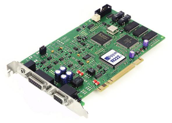
6 CONTENTS OF THIS PACKAGE Thank you for purchasing a Digigram card. The package consists of the following components: * the sound card, * two breakout cables (analog and digital)* * a CD-Rom with drivers, installation notices, FAQs, etc * * the registration card* * this User s Manual *These items are not delivered with the OEM version We invite you to return the completed registration card to be informed in case of new driver releases. Feel free to visit our web site to download the latest driver release*, to get more technical information, consult FAQs, and discover our complete and updated audio product line! * in case you use an application developed by a Digigram partner, make sure that the driver provided for download has been approved by your application supplier! FEATURES is an audio card for PCI bus. It is Universal PCI 32-bit/33 MHz, which means it can be plugged in 5 V PCI slots as well as in 3.3 V keyed PCI slots. The cards are also compatible with PCI-X interfaces. Main hardware features 2 balanced analog mono line inputs Maximum input level selectable by means of the jumper on the card: +22 dbu (jumper ON) +10 dbu (jumper OFF) 2 servo-balanced analog mono line outputs, with software programmable analog and digital gain Maximum output level: +22 dbu 1 digital AES/EBU stereo input The selection of the digital input for recording excludes the selection of the analog inputs. electronically servo-balanced outputs provide automatic level adjustment to accommodate either balanced or unbalanced lines can be used as S/PDIF interface as well 6
7 User s Manual It is possible to use the signal on the digital input as reference sampling clock for recording / playback on the analog I/Os. 1 digital AES/EBU stereo output Always plays the digital version of the analog outputs 1 and 2. 1 mini jack headphone stereo output This output is in parallel of the analog outputs 1 and 2. 2 general purpose inputs and 2 outputs (GPIO). Inter-card synchronization connector. If this connector is not used, synchro switches must be ON. If it is used, one of the connected cards must have the synchro switches ON, all the other linked cards must have the switches OFF. HARDWARE REQUIREMENTS One free PCI slot (5 V or 3.3 V) Minimum Apple Macintosh configuration: PowerMac G3, G4 or G5 with 128 MB RAM. Minimum PC configuration: Pentium III (or equivalent), 128 MB RAM. SOFTWARE REQUIREMENTS The requires installation of the drivers included in VX kit 5.0 or higher. Certain applications designed by Digigram partners may require some particular driver, such as np Runtime 6.01 or higher. For more information, please contact your software vendor. Supported operating systems Mac OS 10.1 and higher Windows 98 SE, Windows ME, Windows 2000, XP *, and Windows Server 2003 can be used as S/PDIF interface as well 32-bit version 7
8 Drivers The table underneath shows the drivers of the VX kit available for each supported operating system. Wave DirectSound ASIO2 Core Audio Windows 98 SE & ME Yes No Yes No Windows 2000 Yes Yes Yes No Windows XP * Yes Yes Yes No Windows Server 2003 Yes Yes Yes No Mac OS X No No No Yes Note: MME driver is sometimes mentioned on software requirement charts. It refers to as Wave. DirectX driver is sometimes mentioned on software requirement charts. It refers to as DirectSound. HARDWARE INSTALLATION The card has to be installed in the computer prior to installing its driver. Installing the card Turn off the computer and disconnect its power cord. Open the computer and position it so that you may easily access its PCI slots. Smoothly insert the card into a free PCI slot. Press it down to position it firmly. Tighten the screw, close the computer, connect the power cord and start the computer. Interrupt and memory address Hardware interrupt and addresses are automatically set up at start-up by the PCI PnP BIOS. SOFTWARE INSTALLATION Please visit the Digigram web site at for the most recent driver. In case you run a specific application developed or installed by a Digigram partner, it might require the use of a specific driver version. In this case, make sure that the updated driver has been approved by your supplier. Under Windows 9x, the driver is a Wave driver. Under Windows 2000, XP *, and Server 2003 *, the driver is DirectSound. In addition, a Wave driver is available, its installation is optional. Under Mac OS X, the driver is a Core Audio driver 32-bit version 8
9 Installation under Mac OS X User s Manual Switch off your Mac, and plug the in a free PCI slot. Restart the machine. Double click on the installation file included on the VX CDROM or downloaded from the Digigram web site. This creates the VX Driver volume on the desktop. Double click on the VXDriver volume icon. A window appears with the following items: 1- Read me first 2- Install VX Control 3- Install the driver 4- Uninstall Read the read me first document. Copy the VX Control to the desktop or to any location in your disk. In the Install VX Driver section, choose. Double click on the driver package driver x-y-z.pkg. Give a login/password that has administrator rights. The installation session opens. Click Continue in the welcome window. Click Continue in the readme window. Select the disk you boot OS X from as destination drive; click Continue. Click Install. Click Continue Installation. Restart the Mac. Removing the VX driver for Mac OS X Open the VX Driver volume. In item 4 - Uninstall, run the uninstaller. Click on the list installed packages icon. Select the Driver x-y-z.pkg package. Select the remove selected package icon (red cross). Give a login/password with administrator rights, and click Ok. Click on Ok, in the alert window. Restart the computer. 9
10 Updating the VX driver for Mac OS X Just install the new version as described above to overwrite the previous version installed. Installation under Windows 98 SE and Millennium If the driver has been downloaded from our web site, it has to be expanded prior to the driver s installation as follows. Double-click on the downloaded file (self-expanding). You can use the default destination location (Windows temporary folder) or select another directory. Turn off the computer and insert the card. Restart the computer. The wizard will detect the card when it is inserted, and prompt for a new driver. Click Next to start the driver installation. Select Display a list of all the drivers to select a specific driver and click Next. Select the <Sound, video and game controllers> category and click Next. Click on the Have Disk button. Browse to the drive where the installation files are located (on the CD- Rom or in the update s extracting destination folder) and click OK. The wizard displays the suitable driver. Click OK to continue. Click on the Next button to start copying the driver files. Click on the Finish button to complete the driver installation. The registry database is updated so that the ASIO compliant programs show the Digigram VX ASIO driver in the list of available ASIO drivers. To take full advantage of your, select the Digigram VX ASIO driver from the application program s specific audio I/O settings. Removing the driver under Windows 98 SE and Millennium To remove the VX driver, make sure the card is present before starting the following procedure: Go to <Start> <Settings> <Control panel> <Add/Remove Programs>. Select the Digigram VX Kit and remove it. Follow the instructions of the InstallShield wizard. 10
11 User s Manual Updating the driver under Windows 98 SE and Millennium Go to <Start> <Settings> <Control panel> <System>. Select the Device Manager tab. Open the Sound, video and game controllers category. Select the Digigram item. Click on the Properties button. Select the Driver tab. Click on the Update driver button. Click Next. Select Display a list of all the drivers to select a specific driver and click Next. Click on the Have Disk button. Browse to the folder where the installation files are located and click OK. The wizard displays the proper driver. Click OK to continue. Click on the Next button to start copying the driver files. Click on the Finish button to complete the driver installation. Reboot is not necessary. Installation under Windows 2000, XP, and Windows Server 2003 Turn off the computer and insert the card. Restart the computer. Windows Plug and Play wizard will detect it and request for a driver. Click on Cancel to close the Windows Plug and Play wizard. Insert the VX kit CD-ROM. The welcome page opens automatically in your web browser. Go to your soundcard s driver page and click on the link of the Windows 2000/XP/Server 2003 version. If you have downloaded the driver package from the web, double-click on the downloaded file (self-extracting). Select the temporary location where to expand the files, and click on Start. Click on Ok in the Finished window. The installation program is then automatically started. Otherwise double-click on setup.exe to start the installation program. Click on Next. Read the License agreement and click on Yes to confirm. 11
12 Select the components to install. Select Wave if you want to install the Wave driver in addition to the DirectSound driver. Click on Next. Under XP and Server 2003, select Continue anyway when the following message is displayed: The software has not passed Windows Logo testing. If you have chosen to install the Wave driver, this message will appear a second time. Select again Continue anyway. Click on Finish. The DirectSound, ASIO, (and Wave if selected) drivers are now installed. Removing the VX driver under Windows 2000, XP, and Windows Server 2003 Go to <Start> <Settings> <Control panel> <Add/Remove Programs>. Select the Digigram VX Kit and remove it. Follow the instructions of the InstallShield wizard. Updating the VX driver under Windows 2000, XP, and Windows Server 2003 Remove the driver as described above. Run the installation program of the new driver, as described above. Note: If you have done an installation without selecting the Wave driver, and you now want to install it, it is necessary to remove the (DirectSound) driver, and then re-install it. 12
13 User s Manual HOW TO CHECK THE INSTALLATION Under Windows Once the driver and the cards are installed according to the procedure described in this manual, you can verify that the card is properly installed and works fine as follows: Go to <Start> <Programs> <Digigram> and select Digigram Control Center. In the Digigram drivers window, select the General Information tab. In the Modules Information window the installed VX Kit modules are displayed along with their versions. In the Digigram drivers window, select the VX Setup tab for a list oft the installed cards. Each card is represented by an icon. Click on the Windows Multimedia properties button to open the Sound & Multimedia properties window. Select the Audio tab. The card devices are listed: o Out #1 in Sound playback, Preferred device. This is a Wave device. o In #1 in Sound recording, Preferred device. This is a Wave device. o Audio Card (WDM) in both Playback and Recording, preferred device. This is a DirectSound device. In case the card is not displayed: make sure that the card is correctly inserted in the PCI slot, and screwed on the PC chassis. if necessary, uninstall the VX Kit package as described in this manual, and re-install it. Under Mac OS X Once the driver and the card are installed, the card is listed in the VX Control panel, the Sound panel, and the Audio Midi Setup panel. You can then use the card with your audio application. 13
14 SETTINGS UNDER MAC OS X Several control panels are available to adjust the settings of the. Some parameters can be adjusted from different panels. If a parameter is modified in a panel, its value is automatically updated in another panel. VX Control panel Use the VX Control panel to set the following parameters of your VX card: choice of VX card (if several VX cards are installed, they are noted as: VX222:0, VX222:1, etc...) latency (Internal Buffer Latency): a low latency value may lead to overloads in the audio causing clicks. If this happens, increase the latency value sample size: 16 or 24 bits selection of the input source: digital, line, line with digital synchronization hardware monitoring: can be activated or disabled by (un)checking "Monitoring Input 1 2" (Monitoring Input 3 4 is inactive). digital input gain from -72 db to +18 db: the active cursor (Digital Input 1 2) allows simultaneous adjustment of the digital gain for both inputs. 14

15 User s Manual 15
.")
16 Sound panel Use the Sound panel to set the following parameters of your VX card: Input tab: - source: digital (VX222 Digital), line (VX222 Line), line with digital synchronization (VX222 Line + Sync). - digital input gain for both inputs (from 72 db to +18 db). Output tab: - analog balance The analog output gain (applied to both output channels) is always accessible at the bottom of the Sound panel window. Note: When adjusting the output balance and the analog output gain from this panel, the positions of the sliders allowing to adjust the analog output gains in the Audio Midi setup panel are updated. When adjusting the digital input gain from this panel, the positions of the sliders allowing to adjust the digital input gains in the Audio Midi setup panel are updated, as well as the slider in the VX Control panel. 16

17 Audio Midi setup panel This panel is accessible via Applications, Utilities. User s Manual Use the Audio Midi setup panel to set the following parameters of your VX card: Hardware monitoring: Play through. Mute of the output: Device Mute. Source: digital (VX222 Digital), line (VX222 Line), line with digital synchronization (VX222 Line + Sync). Audio format for input and output Current Format): sample size, sampling frequency. Digital input gain for each input channel (from 72 db to +18 db). Analog output gain for each output channel. 17

18 VX222V2 SETTINGS UNDER WINDOWS DIGIGRAM WAVE MIXER Note: The Digigram Wave Mixer is only available if the Digigram Wave driver has been properly installed! The Digigram Wave Mixer serves to set input and output levels as well as other settings such as input type and digital data format. General operation Running the program The installation routine installs the Digigram Mixer icon in the Windows taskbar. By default, the program is automatically launched at system start-up. To access the program, double click on its icon or right click on it for a context menu. 18
19 User s Manual In case you have closed the program during your session, you can restart it from the menu <Start><Programs><Digigram><Digigram Mixer>. Run at start-up To enable/disable automatic run at start-up, right click on the Mixer icon in the taskbar, or go to the Mixer <Options> menu. Select/unselect run at startup. General configuration The mixer configuration options allow selection of: input and output nominal level, input and output headroom, input type. The input and output nominal level and input and output headroom define the maximum value of the acceptable input signal. Set the nominal level to the currently used nominal level. The headroom should be set to avoid any risk of overload. If set beyond the installed card s capabilities, the driver automatically sets the correct values. In this case, the displayed values are wrong. The record source selection allows selecting digital input or analog input selection. On the only the first stereo channel may be selected for digital input. Nominal and Headroom apply simultaneously to all four channels. Always on top of the display Right click on the mixer icon in the taskbar, or go to the mixer <Options> menu. Select Always on top. Resetting the faders to their default values Click on the Options menu. Select Reset levels. Selecting the input/output mixer channel Click on the Mixer menu. Select the required board and channel mixer. 19
20 Setting the default values for each mixer line selected Right click on the mixer icon in the taskbar, or go to the mixer Options menu. Select Save current configuration as default. Getting the default configuration values for the mixer line selected Right click on the mixer icon in the taskbar, or go to the mixer Options menu. Select Load default configuration. Leaving the mixer program Click on the right button over the mixer icon in the taskbar. Select Exit. General settings Record source The record source section contains two buttons allowing selection of the input type used. Digital Input: selects the digital input. Analog Input: selects analog input. Clock source This option allows the selection of the synchronization clock source. Automatic: selects the internal clock when analog input is selected, the digital input clock when digital input is selected. Digital: selects the digital input regardless of the source input selection. 20
 Applies an analog gain on the selected output device. Wave out (Output) Applies a digital gain on all files played as well as on software monitoring.")
21 Faders User s Manual Various faders allow you to adjusting input, output and hardware monitoring levels. The faders can be reset by double clicking on their respective buttons. Speakers (Output) Applies an analog gain on the selected output device. Wave out (Output) Applies a digital gain on all files played as well as on software monitoring. Monitoring Applies a digital gain on the hardware monitoring. Analog In As the does not dispose of an adjustable analog input gain, this cursor applies the digital input gain. Digital In (Input) Applies a digital gain to the digital signal coming from the digital input. Advanced settings 21
22 Audio/Data mode In data mode, all digital level processing is disabled in the driver to ensure a digital stream free of any sample modification. This mode must be used to play non-pcm audio data on the digital output (Dolby AC-3 for instance). Note: Digital format Do not listen to the analog output in such a case, as clicking may cause disturbing noises! Sets the digital format of the digital output in real time: AES/EBU (professional) or S/PDIF (consumer). Nominal Out and Headroom Out Sets the nominal line output level and the available headroom during playback at nominal level. Addition of headroom and nominal level must not exceed the maximum output level of the board (+22 dbu). Note: The sum of Nominal Out plus Headroom Out defines the equivalence between the maximum analog level and the maximum digital level (0 dbfs). Nominal In and Headroom In Sets the nominal input level for recording and the available headroom while recording at nominal level. Addition of headroom and nominal level must not exceed the maximum input level of the board (+10 dbu or +22 dbu, depending on the position of the jumper (SW1, cf. appendix) on the board). Note: The does not dispose of an adjustable analog input gain. A modification of Nominal In or Headroom In applies the digital input gain. On, the sum of Nominal plus Headroom must be situated between -8 dbu and +10 dbu if the jumper is in "-10" position (=absent), or between +4 dbu and +22 dbu if the jumper is in "+4" position (=on the board). The sum of Nominal In plus Headroom In defines the equivalence between the maximum analog level and the maximum digital level (0 dbfs). 22

23 User s Manual ASIO CONTROL PANEL FOR PC The purpose of this control panel is to set all the parameters of your Digigram card when used with its ASIO2 driver. It must be launched from the ASIO compatible application you use. Detected Digigram boards are displayed in the left upper corner with their serial number and their I/O stereo pairs. General settings of the selected card are displayed in the right upper corner. IN and OUT settings of the selected device are displayed underneath. General settings Active stereo I/O It is recommended to activate only the required I/Os in order to save CPU resources. 23
24 Clock The clock corresponds to the digital bit clock to which the card refers. When an analog input is selected, the clock source can be either the internal clock or taken from the digital input. As soon as the digital input is selected, the clock is read from this input. The Frequency flip menu allows selecting the sampling frequency of the selected card: 32, 44.1 or 48 khz. It must be set according to the sampling frequency of the project you are working on. Sample size Defines the number of bits per sample. It must be set in accordance with the sample size of the project you are working on. Digital output Defines the format of the digital output signal: Consumer (S/PDIF) or Professional (AES/EBU). Level settings Click on the tab of the I/O device you want to set. Leaving the mouse pointer a few seconds on a slider shows the available settings range (tooltip box). The exact setting value is displayed near each slider. Input The flip box allows switching between the different types of input: line or digital. For any input type, a digital gain can be added to the signal, if necessary. Its default position is in front of the bold dot (0 db). All these input settings apply on both channels of the selected stereo device. 24
25 Output User s Manual The playback digital control applies a digital gain to the selected output (i.e. to what the application plays, including the software monitoring). It can be set for each channel of the selected device, or for both channels at the same time by clicking the Link box. This gain applies to both digital and analog outputs. Its default position is in front of the bold dot. The analog output gain can be set for each channel, or for both channels at the same time by clicking the Link box. This gain only applies to the analog outputs. Its default position is in front of the bold dot, unless you use headphones. In this case, decrease the levels of analog outputs 1 & 2 to prevent you from hearing damage. Monitoring ASIO applications basically use two monitoring modes: software monitoring and hardware monitoring (the latter also known as ASIO direct monitoring ). In software monitoring mode, the recorded signal is immediately played back, just as if it were read from the hard disk. This allows monitoring through effects for instance, but induces latency that can be annoying to the recording musician. In hardware monitoring mode, the recorded signal is directly routed from the inputs to the outputs of the card without passing through your audio application, avoiding the latency in the monitoring path. The monitoring slider controls the hardware monitoring level (ASIO direct monitoring) but does not control the software monitoring. Its default position is in front of the bold dot. It can be set independently for each channel. ASIO compliant applications featuring ASIO direct monitoring control this level directly using their integrated mixer. Time Error Compensation Audio data transfer may suffer from buffer underrun, in most cases due to temporary CPU overload. To avoid the loss of synchronization between input and output signals, click on the Advanced button and select: <Skip samples on outputs to compensate audio time drift> Note: This option can only fix a limited amount of errors. Too many errors occurring will result in a loss of sound quality. To avoid errors, reduce CPU load. 25
26 SPECIFICATIONS CONFIGURATION Bus/Format PCI slave mode Size 175 mm 99 mm Digital Signal Processor at 100 MHz Power requirements (+3.3 V / +5 V / +12 V / 12V) 0.5A / 0.1A / 0.2A / 0.1A Operating: temp / humidity (noncondensing) 0 C/+50 C 5%/90% Storage: temp/humidity -5 C/+70 C 0%/95% (non-condensing) INPUTS / OUTPUTS Analog line inputs (mono) Maximum input/impedance Programmable input gain Digital inputs (stereo) Other inputs Analog line outputs (mono) Maximum output/impedance Programmable output gain Digital outputs (stereo) Other outputs Access to main status bits of digital frame AES11 synchronization Connectors 2 balanced +22 dbu / >10kΩ (jumper ON) +10 dbu / >10kΩ (jumper OFF) digital 1 AES/EBU 2 GPI (dry contact) 2 servo-balanced +22 dbu/low impedance digital and analog 1 AES/EBU headphone (600 Ω), two GPO (relay, 0.5A, 48 VCC) Yes Yes 15-pin SUB-D for analog I/O, 15-pin HD SUB-D for digital I/O, and GPIO; headphone jack (female TRS 3,5 mm) can be used with unbalanced signals can be used as S/PDIF interface as well electronically servo-balanced outputs provide automatic level adjustment to accommodate either balanced or unbalanced lines 26
27 User s Manual AUDIO SPECIFICATIONS Sampling frequencies available A/D and D/A converter resolution Frequency response Signal to noise ratio Programmable from 8 to 50 khz 24 bits 20 Hz 20 khz: ±0.2 db >97 db Distortion + noise at 1 khz <-92 db ( %) Channel phase difference: 20 Hz/20 khz <0.5 /2 Analog channel cross talk at 1kHz <-115 db Note: All measurements are done at Fs=48 khz, in rec+play mode. Results are unweighted. 27
28 APPENDICES SCHEMATIC DIAGRAM XTAL CLOCK GENERATION AES/EBU IN RECEIVE TRANSMIT AES/EBU OUT DSP LINE IN ADC DAC Level adjust LINE OUT Headphones OUT INTERFACE GPIO CONTROL GP OUT GP IN PCI BUS 28
29 LAYOUT J 1 J 2 J 3 SW1 Jumper Switch position (SW 2) Up = OFF (open) Down = ON (closed) User s Manual SW2 J 5 OFF ON SW1: Jumper input impedance: Position Nominal Input Level Maximum Input Level ON +4 dbu +22 dbu OFF -10 dbv +10 dbu SW2: Inter board synchronization: (both levers must be set together) Position Status OFF Slave card ON Master card J1: Headphone connector: (3.5 mm TRS female jack) Contact Signal Sleeve Ground Tip Left channel Ring Right channel J2: Analog cable connector J3: Digital cable connector J5: Inter-card synchronization connector 29
30 ANALOG CABLE DIAGRAM WIRING DIAGRAM Analog Cable Signal number XLR J J10 male J11 male Right OUT Left OUT J12 female Right IN J13 female Left IN 30
31 DIGITAL CABLE DIAGRAM User s Manual WIRING DIAGRAM Digital Cable with GPIOs Signal Number GPI OUT 1A GPI OUT 1B 9-pin SubD GPI OUT 2A GPI OUT 2B J10 female 8 6 shield 6 9 3, 7, 8 GPI IN 1 GPI IN 2 J J11 female XLR AES/EBU SYNC/IN J12 male AES/EBU OUT 31
32 CABLE PINOUT Pin # ANALOG DIGITAL 1 R OUT + GPI OUT 1A 2 GND NC 3 L OUT - NC 4 GND AES/EBU IN - 5 NC AES/EBU IN + 6 R IN - GPI INPUT 2 7 L IN + GND/GPI INPUT COMMON 8 GND GPI INPUT 1 9 R OUT - GND 10 L OUT + NC 11 GND GPI OUT 1B 12 NC GPI OUT 2A 13 R IN + GPI OUT 2B 14 GND AES/EBU OUT + 15 L IN - AES/EBU OUT - 32
D i g i g r a m. VX222HR VX222HR-Mic. Professional Stereo Sound Cards. User s manual
 VX222HR VX222HR-Mic Professional Stereo Sound Cards User s manual For technical support, please contact your system supplier Digigram S.A. Parc de Pré Milliet, 38330 Montbonnot - FRANCE Tel: +33 (0)4 76
LoLa280. Professional multichannel sound card. User manual
 Professional multichannel sound card For technical support, please contact your supplier Digigram S.A. 82/84 Allée Galilée, 38330 Montbonnot-Saint-Martin, FRANCE Tel: +33 (0)4 76 52 47 47 Fax: +33 (0)
LoLa881 LoLa Professional Multichannel Sound Cards. User manual
 LoLa881 LoLa16161 Professional Multichannel Sound Cards For technical support please contact your system supplier Digigram S.A. 82/84 Allée Galilée, 38330 Montbonnot-Saint-Martin, FRANCE Tel: +33 (0)4
PCX1221HR PCX1222HR. Professional Multichannel Sound Cards. User manual
 PCXHR PCXHR Professional Multichannel Sound Cards User manual For technical support, please contact your system supplier Digigram S.A. 8/84 Allée Galilée, 80 Montbonnot-Saint-Martin, FRANCE Tel: (0)4 76
PCX924e PCX924e-Mic PCX22e
 PCX94e PCX94e-Mic PCXe Professional Stereo Sound Cards For technical support, please contact your system supplier Digigram S.A. 8/84 Allée Galilée, 80 Montbonnot-Saint-Martin, FRANCE Tel: + (0)4 76 5 47
PCX1221e PCX1222e. Professional Multichannel Sound Cards. User manual
 PCX11e PCX1e Professional Multichannel Sound Cards User manual For technical support, please contact your system supplier Digigram S.A. 8/84 Allée Galilée, 80 Montbonnot-Saint-Martin, FRANCE Tel: + (0)4
Professional 24-bit USB Audio Interface. User s Guide
 Professional 24-bit USB Audio Interface User s Guide - Copyright 2016-2017 Revision 2, May 2017 www.esi-audio.com INDEX 1. Introduction... 4 1.1 Features... 4 2. Installation... 7 2.1 System Recommendation...
18-in/8-out USB 2.0 Hi-Speed External Recording Interface. User s Guide
 18-in/8-out USB 2.0 Hi-Speed External Recording Interface User s Guide - Copyright 2007 Revision 1, November 2007 www.esi-audio.com INDEX 1. Introduction... 4 1.1 What s in the box... 4 1.2 Key Features...
4-in/6-out USB Recording Interface. User s Guide
 4-in/6-out USB Recording Interface User s Guide - Copyright 2007 Revision 1, June 2007 www.esi-audio.com INDEX 1. Introduction... 4 1.1 What s in the box... 4 1.2 Key Features... 4 2. Description of U46
24-bit USB Audio Interface with S/PDIF I/O. User s Guide
 24-bit USB Audio Interface with S/PDIF I/O User s Guide - Copyright 2008-2018 Revision 5, June 2018 www.esi-audio.com INDEX 1. Introduction... 4 1.1 Key Features... 4 2. Description of... 4 2.1 Front Panel...
USB to Serial Converter User s Guide
 USB to Serial Converter User s Guide Important Note! In order to minimize possible installation problems and/or resource conflicts: Read Me First! About This User s Guide This User s Guide is designed
Bluetooth Micro Dongle User s Guide. Rating: 5V DC 80mA Made in China
 Bluetooth Micro Dongle User s Guide Rating: 5V DC 80mA Made in China Introduction Package Contents USB Bluetooth adapter x 1 Installation CD x 1 (includes Bluetooth software and User s Guide) User s Guide
1.0. User s Guide & Manual. MDC Bluetooth + 56K Modem
 1.0 MDC Bluetooth + 56K Modem User s Guide & Manual Portable of module Federal Communication Commission Interference Statement This equipment has been tested and found to comply with the limits for a Class
SoundWave Pro PCI Quick Installation Guide
 SoundWave Pro PCI Quick Installation Guide Introducing the SoundWave Pro PCI The SoundWave Pro PCI uses bus mastering technology to take full advantage of the PCI bus architecture, while maintaining compatibility
 The FCC Regulation Warning This equipment has been tested and found to comply with the limits for a Class A digital device, pursuant to Part 15 of the FCC Rules and CISPR pursuant to subchapter EN55022
The Hard Disk Sampler Tool Kit! GIGAStation. Owner s Manual.
 The Hard Disk Sampler Tool Kit! GIGAStation Owner s Manual www.egosys.net All rights to this document are reserved. No part of this document may be copied reproduced, or distributed in any form or by any
RAL-24192DM1 Setup Guide
 RAL-24192DM1 Setup Guide Rev. 1.0 15/June/2012 RATOC Systems, Inc. www.ratocsystems.com Osaka, Japan Index 1. Introduction -------------------------------------------------------------------------- 3 1-1.
RAL-DSDHA1 Setup Guide
 RAL-DSDHA1 Setup Guide Rev. 1.0 12/Feb/2013 RATOC Systems, Inc. www.ratocsystems.com Osaka, Japan Index 1. Introduction... 3 1-1.Features...3 2. System requirements... 4 2-1. PC running on Windows 8,7,Vista,XP(SP2
USB Hub-Audio Series. January 1999 A
 Series January 1999 A15-0157-110 FCC COMPLIANCE STATEMENT: This device complies with part 15 of the FCC Rules. Operation is subject to the following two conditions: (1) This device may not cause harmful
High Quality 4-in / 4-out PCIe Audio Interface. User s Guide
 High Quality 4-in / 4-out PCIe Audio Interface User s Guide - Copyright 2008 Revision 1, December 2008 www.esi-audio.com INDEX 1. Introduction... 4 2. Description of... 4 2.1 PCIe card connectors... 4
U-DAC8. User Manual 8-CHANNEL HIGH-RESOLUTION USB DAC
 U-DAC8 8-CHANNEL HIGH-RESOLUTION USB DAC User Manual minidsp Ltd, Hong Kong / www.minidsp.com / Features and specifications subject to change without prior notice 1 Revision history Revision Description
SoundWave Pro 2000 Quick Installation Guide
 SoundWave Pro 2000 Quick Installation Guide Introducing the SoundWave Pro 2000 The SoundWave Pro 2000 is a high performance multimedia sound card which takes full advantage of the PCI bus architecture,
AHA PCI-to-Fast SCSI Host Adapter. Fast SCSI Connection for High-Performance SCSI Peripherals for Pentium PCs
 R AHA-2920 PCI-to-Fast SCSI Host Adapter Fast SCSI Connection for High-Performance SCSI Peripherals for Pentium PCs Introduction This installation guide provides the instructions needed to install and
User's Guide. Analog Expansion Board for DIGI96/8 Series and Hammerfall Serie 4/8 Channels, 24 Bit
 User's Guide Analog Expansion Board for DIGI96/8 Series and Hammerfall Serie 4/8 Channels, 24 Bit Contents 1 Introduction...3 2 Package Contents...3 3 Hardware Requirements...3 4 Technical Specifications...3
Port PCI Quick Installation Guide
 1394 3-Port PCI Quick Installation Guide Introducing the 1394 3-Port PCI The 1394 3-Port PCI is designed to connect DV camcorders, hard disk drives, scanners, printers and other 1394 audio/video devices
Overview. Rev. 1.5c. November 17, 2003
 Overview Rev. 1.5c November 17, 2003 Copyright 2003 Digigram. All rights reserved. No portion of this document may be reproduced without prior written consent from Digigram. The copyright protection claimed
User's Guide. Analog Expansion Board for DIGI96/8 Series, Hammerfall Series and HDSP /8 Channels, 24 Bit
 User's Guide Analog Expansion Board for DIGI96/8 Series, Hammerfall Series and HDSP 9652 4/8 Channels, 24 Bit Contents 1 Introduction... 3 2 Package Contents... 3 3 Hardware Requirements... 3 4 Technical
Installation Guide AMM-1525M/1510M/525M. SCSI Audio Host Adapters and Sound Cards
 R Installation Guide AMM-1525M/1510M/525M SCSI Audio Host Adapters and Sound Cards 1 Getting Started This document provides the basic information needed to quickly configure and install the Adaptec AMM
SoundWave Pro PCI Quick Installation Guide
 SoundWave Pro PCI Quick Installation Guide Introducing the SoundWave Pro PCI The SoundWave Pro PCI provides 3D sound effects and supports DirectSound 3D TM, MPU-401, GM and is fully compatible with Sound
VisionRGB-PRO User Manual
 VisionRGB-PRO User Manual Datapath Limited Alfreton Road, Derby, DE21 4AD, England Tel: +44 (0) 1332 294441 Fax: +44 (0) 1332 290667 Email: sales@datapath.co.uk Web: http://www.datapath.co.uk 1 26 Oct
1 Mic-In / 1 Guitar-In, 2-Out Professional vocal recording USB Interface. User manual
 1 Mic-In / 1 Guitar-In, 2-Out Professional vocal recording USB Interface User manual Important Safety Instructions 1. Read this manual thoroughly before using this unit. 2. Keep this manual for future
2.1 Operating System : Microsoft Widows 98/ME/NT/2000/XP. 3.1 Unplug the Modular Plug from the telephone and plug it in one of the Dual Modular Jack.
 PC Recorder User s Manual 1. About PC Recorder The PC Recorder is a system which enables users to record the phone conversation to the PC and to search and play back the recorded contents later when needed
Copyright. Warning. Warning! Communications & Safety Regulation Information
 96i I/O Copyright 2006 Digidesign, a division of Avid Technology, Inc. All rights reserved. This guide may not be duplicated in whole or in part without the express written consent of Digidesign. Avid,
WLAN a+b+g mini-pci Module
 WLAN a+b+g mini-pci Module User Manual Model: EM-500AG Version: 1.0 Feb 2003 Copyright Statement No part of this publication may be reproduced, stored in a retrieval system, or transmitted in any form
SoundWave 7.1 PCI Quick Installation Guide
 SoundWave 7.1 PCI Quick Installation Guide Introducing the SoundWave 7.1 PCI The SoundWave 7.1 PCI transforms your PC into a home theater system with multi-channel surround sound. Features Compliant with
RocketRAID 3622/3620. SATA 6Gb/s PCI-Express 2.0 x 8 RAID HBA
 RocketRAID 3622/3620 SATA 6Gb/s PCI-Express 2.0 x 8 RAID HBA Quick Installation Guide V1.00 May. 2, 2013 1 Table of Contents Hardware Installation... 3 Kit Contents... 3 Board Layout... 3 Installing the
ForwardT. Software setup. SoftLab-NSK, Ltd. Revision from 09 September 2005 ForwardT Software 3.9.0
 ForwardT Software setup Revision from 09 September 2005 ForwardT Software 3.9.0 SoftLab-NSK, Ltd. Notice The information in this document is subject to change without prior notice in order to improve reliability,
AIRNET 54Mb b/g High Power USB Adapter. User s Manual
 AIRNET 54Mb 802.11b/g High Power USB Adapter User s Manual FCC Certifications Federal Communication Commission Interference Statement This equipment has been tested and found to comply with the limits
RocketRAID 272x/271x Host Adapter
 RocketRAID 272x/271x Host Adapter Quick Installation Guide V2.2 1 Content HighPoint RocketRAID 272x/271x Series PCI-Express 2.0... 3 Kit Contents... 3 Installing the RocketRAID Series Host Adapter... 4
RocketU 1022C Host Controller
 RocketU 1022C Host Controller Quick Installation Guide V1.0 Jan. 21, 2013 1 Table of Contents HighPoint RocketU 1022C... 3 Kit Contents... 3 Board Layout... 4 Installing the RocketU Series Host Adapter...
TF-3239DL 10/100Mbps PCI Network Adapter
 Rev: 1.1.0 1910010553 COPYRIGHT & TRADEMARKS Specifications are subject to change without notice. is a registered trademark of TP-LINK TECHNOLOGIES CO., LTD. Other brands and product names are trademarks
54M Wireless LAN CardBus Card
 54M Wireless LAN CardBus Card User s Manual Ver.2.0 Federal Communication Commission Interference Statement This equipment has been tested and found to comply with the limits for a Class B digital device,
Check the contents of the package
 Read this first! UA-4FX Owner s Manual Copyright 2005 ROLAND CORPORATION All rights reserved. No part of this publication may be reproduced in any form without the written permission of ROLAND CORPORATION.
100BASE-TX/10-B REX-CB81U. User Guide. November 1998 First Edition
 100BASE-TX/10-B ASE-TX/10-BASE-T Network CardBus PC Card REX-CB81U User Guide November 1998 First Edition REX-CB81U User Guide CONTENTS FCC Statement 1 1. Introduction 3 1-1. Features 3 1-2. Trademarks
Unpack the package contents and verify that you have the following: Model PA301 Network Card Telephone cable (10 ft) Resource CD
 Resource CD") Start Here Instructions in this guide are for users of Windows 95 and Windows 98 who are installing the Model PA301 Network Card. For instructions on installing and verifying the Windows network driver,
Start Here Instructions in this guide are for users of Windows 95 and Windows 98 who are installing the Model PA301 Network Card. For instructions on installing and verifying the Windows network driver,
FlyTV MCE Installation Guide Animation Technologies Inc.
 FlyTV MCE Installation Guide Animation Technologies Inc. www.lifeview.com Ver: 1.0 Copyright and Trademark Notice Copyright 2005 by Animation Technologies Inc. All rights reserved. Specifications and
! Hardware: USB-Serial adapter, USB type A to type B cable. Software: USB-Serial driver on CD-ROM
 Congratulations on your purchase of the USB-Serial adapter. This device provides a simple and easy way to connect Universal Serial Bus (USB) and Serial port interface. With the advantage of USB port, users
USB Wireless Network Adapter User s Manual
 USB Wireless Network Adapter User s Manual Rev 0.9 Regulatory compliance FCC Warning This equipment has been tested and found to comply with the limits for a Class B digital device, pursuant to part 15
Wireless-N PCI Adapter User Manual
 Wireless-N PCI Adapter User Manual V1.0 2010-06-28 FCC Certifications Federal Communication Commission Interference Statement This equipment has been tested and found to comply with the limits for a Class
IEEE 1394 PC-Card Interface Adapter
 IEEE 1394 PC-Card Interface Adapter Rev. A02 Congratulations on your purchase of the Lava IEEE 1394 Interface Adapter. The Lava IEEE 1394 Interface Adapter is a PC bus card for connecting high-performance
RocketRAID 2760A. 6Gb/s SAS/SATA Host Adapter. Quick Instal l ation Guide v1.1
 RocketRAID 2760A 6Gb/s SAS/SATA Host Adapter Quick Instal l ation Guide v1.1 Contents HighPoint RocketRAID 2760A PCI-Express 2.0 x16... 3 Hardware Installation... 4 Kit Contents... 4 Installing the RR2760A
OriGain Integrated Amplifier Owner s Manual
 OriGain Integrated Amplifier Owner s Manual Models: A250, AD250 Got a Question or Need Help? Email our technical support team at: support@miccatron.com for personalized assistance with the setup and use
Installation Guide AVA-2902E/I. PCI-to-Fast SCSI Host Adapters. PCI SCSI Host Adapter with Internal or External Connector
 Installation Guide AVA-2902E/I PCI-to-Fast SCSI Host Adapters PCI SCSI Host Adapter with Internal or External Connector R 1 Installing the Host Adapter and SCSI Device WARNING: Before you start, turn OFF
RocketCache 32xx Series HBA
 RocketCache 32xx Series HBA Add SSD Performance to Your HDD Storage User s Guide v1.2 1 Contents HighPoint RocketCache 32xx Series Host Adapter...3 Kit Content...3 Hardware Installation...4 RocketCache
 $ERXW
$ERXW RocketRAID 2720C2. User Manual V1.00
 RocketRAID 2720C2 User Manual V1.00 Nov. 6, 2013 1 Table of contents 1. HighPoint RocketRAID 2720C2 -Cross-Synch Storage Solution... 3 2. Kit Contents... 3 3. Installing the RocketRAID 2720C2 Host Adapters...
XT-SW21-4K18G. Introduction. User Manual. Key Features XT-SW21-4K18G USER MANUAL
 XT-SW-K8G USER MANUAL XT-SW-K8G User Manual Introduction Our XT-SW-K8G K HDMI.0 switcher distributes x HDMI sources to a single output. The switcher supports full HDMI.0 and HDCP. with video resolutions
DVI KVM Switch user manual Model
 DVI KVM Switch user manual Model 156066 INT-156066-UM-0808-01 introduction Thank you for purchasing the INTELLINET NETWORK SOLUTIONS DVI KVM Switch, Model 156066. This convenient device lets you control
Digital to Analog Converter
 NuForce Optoma NuForce DAC-80 DAC80 Digital Class-leading to Analog Converter Digital to Analog Converter 44.1k 88.2k 176.4k 48.0k 96.0k 192.0k User s User s Manual Manual ALDACBZ FCC Notice - Declaration
USB-C Multiport Dock with Power Charging USER MANUAL UH3230
 USB-C Multiport Dock with Power Charging USER MANUAL UH3230 EMC Information Federal Communication Commission Interference Statement: This equipment has been tested and found to comply with the limits for
1394 DV-Cam Kit Quick Installation Guide
 1394 DV-Cam Kit Quick Installation Guide Introducing the 1394 DV-Cam Kit The 1394 DV-Cam Kit is designed to add three 1394 (FireWire) ports to your computer for easy connection to DV camcorders, hard disk
EN-9235TX-32 Quick Installation Guide
 EN-9235TX-32 Quick Installation Guide 09-2012 / v2.0 1 COPYRIGHT Copyright Edimax Technology Co., Ltd. all rights reserved. No part of this publication may be reproduced, transmitted, transcribed, stored
Hardware Installation 1. Install two AA batteries in the mouse. Pairing Process in Vista and Windows XP SP2
 Hardware Installation 1. Install two AA batteries in the mouse. Pairing Process in Vista and Windows XP SP2 1. Open the Windows control panel, then select Bluetooth devices. 2. Click Add.. 3. Select My
4-In / 2-Out with +48V Phantom Power Recording USB Interface. User manual
 4-In / 2-Out with +48V Phantom Power Recording USB Interface User manual Important Safety Instructions 1. Read this manual thoroughly before using this unit. 2. Keep this manual for future reference. 3.
GrabBeeX+ USB 2.0 AV Grabber. User's Manual
 GrabBeeX+ USB 2.0 AV Grabber User's Manual FEDERAL COMMUNICATIONS COMMISSION This device complies with Part 15 of the FCC Rules Operation is subject to the following two conditions: this device may not
Fast SCSI Pro Quick Installation Guide
 Introducing Your Fast SCSI Pro Your Fast SCSI Pro is a high performance, Plug-and-Play PCI-bus master SCSI host adapter which supports connectivity to up to seven external SCSI devices. These devices include:
USER S MANUAL USB TO Serial Adapter
 USER S MANUAL USB TO Serial Adapter 1. Introduction Congratulations on your purchase of the USB-Serial adapter. This device provides a simple and easy way to connect Universal Serial Bus (USB) and Serial
Cyber PCI I/O Quick Installation Guide
 Cyber PCI I/O Quick Installation Guide Introducing the Cyber PCI I/O The Cyber PCI I/O high-speed serial and parallel I/O card family provides a complete solution for serial and parallel device connections.
100BASE-TX/10-BASE-T Network CardBus PC Card for PowerBook & MacOS 8.1/8.5 CB81PB. User Guide
 100BASE-TX/10-BASE-T Network CardBus PC Card for PowerBook & MacOS 8.1/8.5 CB81PB User Guide Rev. 1.1 Mar 2000 REX-CB81PB User Guide FCC Statement 1 1. Introduction 3 1-1. Features 3 1-2. Trademarks 3
RocketU 114xE Host Controller
 RocketU 114xE Host Controller Quick Installation Guide V1.00 Jul. 30, 2013 1 Table of Contents HighPoint RocketU 1144E... 3 Kit Contents... 3 Board Layout... 4 Installing the RocketU Series Host Adapter...
N-DAC8. User Manual 8-CHANNEL AVB/ETHERNET DAC
 N-DAC8 8-CHANNEL AVB/ETHERNET DAC User Manual minidsp Ltd, Hong Kong / www.minidsp.com / Features and specifications subject to change without prior notice 1 Revision history Revision Description Date
Rocket 272x 6Gb/s SAS/SATA Host Adapter Quick Installation Guide
 Rocket 272x 6Gb/s SAS/SATA Host Adapter Quick Installation Guide v1.1 1 Contents HighPoint Rocket 272x...3 Hardware Installation...4 Installing the Rocket 272x Adapter...3 Using the Rocket 272x BIOS...4
MONTANa. User s Guide
 MONTANa User s Guide Dakota, Montana, Sierra, SoDA, Tango24, and Zulu are trademarks of Frontier Design Group, LLC. All other trademarks and registered trademarks are the property of their respective holders.
AHA-3980/3980W AHA-3985/3985W
 Quick Reference: Hardware Installation AHA-3980/3980W AHA-3985/3985W MultiChannel PCI-to-SCSI RAID Adapters R This guide explains how to install the AHA -398x RAID adapters: the AHA-3980, AHA-3980W, AHA-3985,
CDU-680DORA Mobile Broadband USB Modem+Disk TM
 CDU-680DORA Mobile Broadband USB Modem+Disk TM Quick Installation Guide 2007 Franklin Wireless, Corp. All rights reserved. No reproduction in whole or in part without prior written approval. Regulatory
USER S MANUAL Multi-LinQ USB2.0
 USER S MANUAL Multi-LinQ USB2.0 CONTENT 1. Introduction----------------------------------------------------------------------------------2 2. Package Content--------------------------------------------------------------------------2
APC-100. IEEE g Wireless USB Adapter. User s Guide v1.0
 APC-100 IEEE 802.11g Wireless USB Adapter User s Guide v1.0 FCC Certifications Federal Communication Commission Interference Statement This equipment has been tested and found to comply with the limits
Low Profile PCI I/O Quick Installation Guide
 Low Profile PCI I/O Quick Installation Guide Introducing the Low Profile PCI I/O The Low Profile PCI I/O conforms to the new PCI card form factor standard made for space constrained system designs. Since
Instruction Guide. Low-Profile 2-port IEEE 1394 FireWire PCI Card with Video Editing Software PCI1394_2LP
 FIREWIRE CARD Low-Profile 2-port IEEE 1394 FireWire PCI Card with Video Editing Software PCI1394_2LP Instruction Guide * Actual product may vary from photo The Professionals Source For Hard-to-Find Computer
USER MANUAL USB Bluetooth Adapter
 USER MANUAL USB Bluetooth Adapter UBT-120 CONTENT 1. Introduction--------------------------------------------------------------------------------- 2 2. Package Content-------------------------------------------------------------------------
Quick Setup The MVi is compatible with most devices that have a USB or Lightning connector. Touch Panel Interface Controls. MVi. Overview.
 MVi Digital Audio Interface General Description The Shure MVi is a compact digital audio interface used to connect a microphone, guitar, or other instrument to a computer or mobile device. Audio and power
USB SoundWave Optical 5.1 Quick Installation Guide
 USB SoundWave Optical 5.1 Quick Installation Guide Introducing the USB SoundWave Optical The USB SoundWave Optical 5.1 transforms your PC into a home theatre system with multi-channel surround sound. Features
EN-9260TX-E User Manual
 EN-9260TX-E User Manual 09-2012 / v2.0 1 COPYRIGHT Copyright Edimax Technology Co., Ltd. all rights reserved. No part of this publication may be reproduced, transmitted, transcribed, stored in a retrieval
Serial ExpressCard 4 port 16C950 Serial ExpressCard
 Serial ExpressCard 4 port 16C950 Serial ExpressCard EC4S950 Actual product may vary from photo FCC Compliance Statement This equipment has been tested and found to comply with the limits for a Class B
Single Port Serial PC Card User Manual
 Single Port Serial PC Card User Manual FCC COMPLIANCE STATEMENTS This equipment has been tested and found to comply with the limits for a Class B digital device, pursuant to Part 15 of the FCC Rules.
Ethernet Powerline Adaptor. User Manual
 Ethernet Powerline Adaptor User Manual Copyright The contents of this publication may not be reproduced in any part or as a whole, stored, transcribed in an information retrieval system, translated into
Installation Guide AHA -1530P/1532P. Plug and Play AT-to-SCSI Host Adapter with SCSISelect Utility
 R Installation Guide AHA -1530P/1532P Plug and Play AT-to-SCSI Host Adapter with SCSISelect Utility Note: Read the AHA-1530P/1532P Getting Started guide first when you are ready to install your AHA-1530P/1532P
LifeView FlyTV Platinum Gold Series Installation Guide with PowerCinema 3
 LifeView FlyTV Platinum Gold Series Installation Guide with PowerCinema 3 P/N: ************* Ver: 3.20.000.0 Date: 2004-05-20 Copyright and Trademark Notice 2003 by Animation Technologies Inc. All rights
ThinkPad Bluetooth Laser Mouse User Manual
 ThinkPad Bluetooth Laser Mouse User Manual About this manual Thank you for your purchase of this Bluetooth mouse set. This topics covered in this manual are listed as following. (This mouse will be sold
User Manual Bluetooth USB Dongle
 User Manual Bluetooth USB Dongle BTDG-40S 1. What s in the box? 1 2. General guidance 1 3. How to use with Native Windows 10 PC Plug and play 1 3.1) Windows own Bluetooth driver Auto installation 1 3.2)
Instruction Guide. 2 Channel Ultra ATA/100 PCI Card PCI2IDE100. The Professionals Source For Hard-to-Find Computer Parts. Revised: December 5, 2002
 IDE CARD 2 Channel Ultra ATA/100 PCI Card PCI2IDE100 Instruction Guide * Actual product may vary from photo Revised: December 5, 2002 The Professionals Source For Hard-to-Find Computer Parts 7 FCC COMPLIANCE
IEEE g Wireless PC Card. User s Guide
 IEEE 802.11g Wireless PC Card User s Guide FCC Certifications Federal Communication Commission Interference Statement This equipment has been tested and found to comply with the limits for a Class B digital
5.1.5 Digital Mixer Outputs Physical Outputs Sample Clock Generator Sample Clock Sources
 Contents 1 Introduction...5 1.1 Overview...5 1.2 Features...6 1.3 Before you begin...6 1.4 In the box...7 1.5 System requirements...7 1.5.1 Windows...7 1.5.2 Macintosh...7 1.6 Nomenclature used in this
PC Connection and Battery Charger DOCKING STATION. for Quest digital recorder. Operating Instructions
 PC Connection and Battery Charger DOCKING STATION for Quest digital recorder Operating Instructions Published by Dictaphone Corporation (U.S.) Stratford, Connecticut Disclaimer Dictaphone Corporation (U.S.)
PT-9500PC. ... PT-9500PC
 Quick Reference PT-9500PC. PT-9500PC....,. Federal Communications Commission (FCC) Declaration of Conformity (For USA Only) Responsible Party: Brother International Corporation 100 Somerset Corporate Boulevard
2-Port Pocket USB KVM switch. Users Manual (DS )
") 2-Port Pocket USB KVM switch Users Manual (DS-11402-1) Index 1. INTRODUCTION 2 1.1 FEATURES.... 2 1.2 PHYSICAL DIAGRAM...... 3 1.3 PACKAGE CONTENTS........3 2. SPECIFICATIONS.4 2.1 GENERAL... 4 3. INSTALLING
2-Port Pocket USB KVM switch Users Manual (DS-11402-1) Index 1. INTRODUCTION 2 1.1 FEATURES.... 2 1.2 PHYSICAL DIAGRAM...... 3 1.3 PACKAGE CONTENTS........3 2. SPECIFICATIONS.4 2.1 GENERAL... 4 3. INSTALLING
Introducing the SoundWave 7.1 PCI. The SoundWave 7.1 PCI transforms your PC into a home theater system with multi-channel surround sound.
 SoundWave 7.1 PCI Quick Installation Guide Introducing the SoundWave 7.1 PCI The SoundWave 7.1 PCI transforms your PC into a home theater system with multi-channel surround sound. Features Compliant with
Online Manual Choose one of the following categories: Getting Started Guide Software User s Guides Technical Specifications Compliance Information
 Online Manual Choose one of the following categories: Getting Started Guide Software User s Guides Technical Specifications Compliance Information Part Number 137-40178-50 User s Guides Click on your product:
MARC 2. User s Guide
 MARC 2 User s Guide The Marc 2 conforms the following standards: EN 55022: 1998 + A1: 2000 + A2: 2003; class A EN 55024: 1998 + A1: 2000 + A2: 2003; class A In order for an installation of this product
Auricon 4.4. Manual ABN
 ABN 66 169 561 871 Auricon 4.4 Manual Overview The Auricon 4.4 is a professional-quality audio input-output card designed in Australia by Innes Corporation. It is supplied with a Windows WDM driver to