Workflow description for Feeder Automation with FASE
|
|
|
- Shauna Walsh
- 6 years ago
- Views:
Transcription
1 FASE_Workflow_Descriprion_ docx Page: 1 / 51 Workflow description for Feeder Automation with FASE Author Name Department Version Date Markus Spangler / Leonid Borisuk IC SG EA PRO LM2 / SYS OP TRC V Updates Chapter / Pages changed Version Object and reason of change/ Reference to change requirements 1
2 FASE_Workflow_Descriprion_ docx Page: 2 / 51 Table of contents 1. INTRODUCTION 3 2. FASE V2.00: INSTALLATION DIGSI INSTALLATION DIGSI DEVICE DRIVER INSTALLATION FASE INSTALLATION PROCESS FASE: TOPOLOGY 5 3. FASE - DECENTRALIZED LOGIC FASE - PROTECTION AND COMMUNICATION SETTINGS FASE - DEFINITION OF SEQUENCES FASE - CREATE DIGSI PROJECT DIGSI - CHANGES IN THE DIGSI PROJECT FASE V CENTRALIZED LOGIC PREPARATION AND SW REQUIREMENTS CREATION OF PROJECT IN FASE ACTIONS REQUIRED IN DIGSI PROJECT CREATION OF SICAM PAS PROJECT CREATION OF SICAM SCC PROJECT 51 2
3 FASE_Workflow_Descriprion_ docx Page: 3 / Introduction Feeder Automation Sequence Editor (FASE) offers the following features: - Automatic creation of DIGSI project with all SIPROTEC devices for your feeder arrangement - Automatic creation of IEC61850 station - Automatic creation GOOSE messages necessary to perform the configured Feeder Automation Apps - Automatic creation of CFC (PLC) logic used to perform the configured Feeder Automation Apps For using of decentralized logic, where the information exchange is done by GOOSE messages between the devices please follow description in the Chapter 2 of this document. Since the FASE V2.00 the user of FASE can transfer the Feeder Automation logic to the substation automation system like SICAM PAS and control and monitor your feeders using SICAM SCC. The necessary steps for configuring of centralized logic of Feeder Automation are described in the Chapter 3 of this document. After the use of FASE you will be able to initialize your SIPROTEC devices and to start the test of the Feeder Automation Apps in your feeder arrangement. In case of centralized solution the necessary files with logic for importing in the SoftPLC of SICAM PAS will be generation by FASE. 3

4 FASE_Workflow_Descriprion_ docx Page: 4 / FASE V2.00: Installation 2.1. DIGSI Installation FASE V2.00 is a standalone software. With FASE you can prepare your feeder automation project with most of the needed settings and applications. Created FASE projects can be saved, exported and imported to other FASE PCs. To create a final DIGSI project, including all devices with necessary FA logic and GOOSE messages (for decentralized logic) you need a installed DIGSI 4 at the same hardware. You need at least DIGSI 4.87 to run FASE V 2.0 successfully DIGSI Device Driver Installation Install the DIGSI device driver for 7SC80 for FASE 2.00 firmware version V4.01 is needed. Newer FASE versions or additional service pack may need newer device firmware versions. 2.3 FASE Installation Process 4

5 FASE_Workflow_Descriprion_ docx Page: 5 / 51 Please copy the FASE license key file ( FASE.LIC ) file in the FASE.exe folder (e.g. C:\Program Files\Siemens Energy\FASE). Please order the necessary license via MLFB in Berlin or ask the Lifecycle Manager markus.spangler@siemens.com if not yet available. 2.4 FASE: Topology As the result out of FASE a complete DIGSI project will be created (including a mode switch controlling the modes of the feeder arrangement and two HMI devices for decentralized logic. Mode switch is necessary for the Feeder Automation function, the one or both HMI devices can be deleted in the newly created DIGSI project, if not needed). Before using FASE, please ensure the correct device templates are used in the project. The following MLFB number for mode switch and HMI devices are predefined in FASE: - Mode Switch (MS): 7SC80221AB973FA0+L0R - HMI: 7SJ64155EC923FG7+L0R For any reasons you can exchange the dex and xml-files in the following folders: Pls. ensure that the new dex and xml-files still contain all necessary predefinitions (matrix, CFC) for the decentralized feeder arrangement. 5

6 FASE_Workflow_Descriprion_ docx Page: 6 / 51 If you change the mode switch or HMI device you have to export the changed *.dex and *.xml files from DIGSI in the folder C:\Program Files\Siemens Energy\DIGSI 4\FASE\ControlDevices\HMI or C:\Program Files\Siemens Energy\DIGSI 4\FASE\ControlDevices\ModeSwitch. 6

7 FASE_Workflow_Descriprion_ docx Page: 7 / FASE - Decentralized Logic Create a new project Add device templates into the device template section if needed. 7

.")
8 FASE_Workflow_Descriprion_ docx Page: 8 / 51 Use predefined templates for your switching devices, which are available in SIPROTEC compact Sharepoint/Internet. You can manipulate the predefined templates (*.dex files) in DIGSI with regards to your needs. But do not delete any Feeder Automation related settings in the predefined templates (CFC logic and matrix indications). After adapting the templates to your needs, please export the dex and the xml-file out of DIGSI to import it to FASE. 8


9 FASE_Workflow_Descriprion_ docx Page: 9 / 51 Insert switching devices in your power grid per Drag&Drop, which are corresponding to your feeder topology. After completion check the box Complete topology. 9


10 FASE_Workflow_Descriprion_ docx Page: 10 / 51 Define the Normally Open Point (NOP) in your grid. Press Add NOP and then choose with double click the NOP. If you need several NOPs, press Add NOP once more again. Up to four NOPs are possible. Red is always the colour for switch closed or source energized, green is always the colour for switch opened or source deenergized. After choosing check the box Complete NOP FASE - Protection and communication settings Press Properties to go to protection and communication settings of your SIPROTEC devices. 10

.")

11 FASE_Workflow_Descriprion_ docx Page: 11 / 51 Here you can set the most relevant protection and communication parameters of used devices. Copy and paste amongst the devices is very easy possible (see pictures below). With the right click on the device you can copy or export the settings and then paste or import in the other one. You can also select the group of settings and transfer it to neighbour devices by pulling of the selection corner like in MS Excel application. 11

12 FASE_Workflow_Descriprion_ docx Page: 12 / 51 In the Communication Settings you can define the IP addresses of your SIPROTEC devices ( IP Address ). For the Communication device IP Address insert the IP addresses of dedicated communication equipment, e.g. WIMAX subscriber units or WiFi access points. In the Project settings tab you decide to work with traditional over current or with new selective and adaptive differential protection FASE - Definition of sequences Here you define the sequences for the application you want to use in the feeder arrangement. There are two default folders to define the isolation and restoration sequences. Isolation: there are two already defined steps in each isolation sequence Normal step and Trigger step. Press Add step and define the next steps for your grid until the fault has been isolated. In each step you can define by double click only one position change of switching device. After definition of the last step check the box Complete sequence. 12

13 FASE_Workflow_Descriprion_ docx Page: 13 / 51 Define isolation sequences for all possible locations of a fault (A, B,C, etc.). Restoration: there is one already defined step Trigger step, which is the last step in corresponding isolation sequence. Use the buttons Add step, Delete last step and Reset steps to configure the restoration sequences for the case the fault has been eliminated and you wish to go back to the initial configuration of your grid. After the sequence has been created press Complete sequence. 13

 To define a new folder for your own")

14 FASE_Workflow_Descriprion_ docx Page: 14 / 51 Define restoration sequences for all possible locations of a fault (A, B, C etc.) To define a new folder for your own sequences/applications click rights on Sequences and then Add folder. In the properties window you decide which operation inputs have to be considered for this specific application: 14


15 FASE_Workflow_Descriprion_ docx Page: 15 / 51 Add a sequence to the created application: In the section Sequence modes set the modes which should be valid for your sequence. Then define your sequences Save your FASE project. 15


16 FASE_Workflow_Descriprion_ docx Page: 16 / FASE - Create DIGSI project Choose the name of future DIGSI project and their location on your hard drive and press Create. If you check the box Create communication devices the FASE will create ICD files for all communication devices in the DIGSI project. These will be also included in the SCD file of the IEC61850 station. If you did not save the FASE project before you get the message to save the project. In the window DIGSI project creation progress you see the report or error messages while creation of DIGSI project. 16
17 FASE_Workflow_Descriprion_ docx Page: 17 / 51 17

18 FASE_Workflow_Descriprion_ docx Page: 18 / DIGSI - Changes in the DIGSI project In the DIGSI project delete HMI1 or HMI2 device if it is not needed and you use SICAM PAS and SCC for monitoring and controlling of your grid. If HMI devices are used open the parameter set and manipulate the predefined display settings with regards to your needs. Go the normal DIGSI workflow if needed, e. g. make other changes in DIGSI files or IEC61850 station. It is recommended not to change any FA related settings (incl. IED names and addresses) like CFC, GOOSE, Indications in the matrix etc. The created ICD files for communication devices are available in SCD as well. In that way you can monitor all communicating devices in diagnostic tools like Netview. Afterwards you can download the parameter set to the devices and test the feeder arrangement with all configured applications with FAST for the decentralized logic using GOOSE. 18

19 FASE_Workflow_Descriprion_ docx Page: 19 / FASE V Centralized Logic 4.1. Preparation and SW requirements You need at least DIGSI V4.87 and DIGSI driver V for 7SC80 device to run FASE V 2.00 successfully. If older versions of DIGSI or FASE are already installed, please uninstall it before using of centralized solution with FASE V Creation of project in FASE Drag&Drop the switching devices from the folder with templates into your topology. 19


20 FASE_Workflow_Descriprion_ docx Page: 20 / 51 After completing of topology confirm with Validate and complete topology. After that, each switching device gets the name like P1, P2 etc and line section gets the designation like C1, C2 etc. The next step is defining of Normal Open Point (NOP). 20


21 FASE_Workflow_Descriprion_ docx Page: 21 / 51 In the tab Properties you can configure protection and communication settings of all devices in your topology (please refer to Chapter 3.1). 21


22 FASE_Workflow_Descriprion_ docx Page: 22 / 51 In the tab Sequences you define the automatic switching sequences for Isolation of fault on sections, ILS, Source Transfer and Restoration etc. (please refer to Chapter 3.2). After configuring the sequences, save the project and go to the tab Create project. Define the location of DIGSI project and SICAM files and start creation with Create button. 22

23 FASE_Workflow_Descriprion_ docx Page: 23 / 51 In the progress window you can see warnings and errors during the creation of DIGSI and SICAM data. 23


24 FASE_Workflow_Descriprion_ docx Page: 24 / Actions required in DIGSI project After creation of DIGSI project by FASE without warnings or errors open the newly created DIGSI project. Add the time master in the DIGSI project, if necessary. 24


25 FASE_Workflow_Descriprion_ docx Page: 25 / 51 Open the properties page of IEC61850 station. Add the time master to the station. 25


26 FASE_Workflow_Descriprion_ docx Page: 26 / 51 Update all parameter sets in the station. After that open each device, compile the CFC charts, save and close it. Open the IEC61850 station and define the time master as First timer. 26

")
27 FASE_Workflow_Descriprion_ docx Page: 27 / 51 Update all parameter sets in the properties of IEC61850 station. Save and export the IEC61850 station (SCD file) for importing in the SICAM PAS. 27
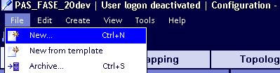
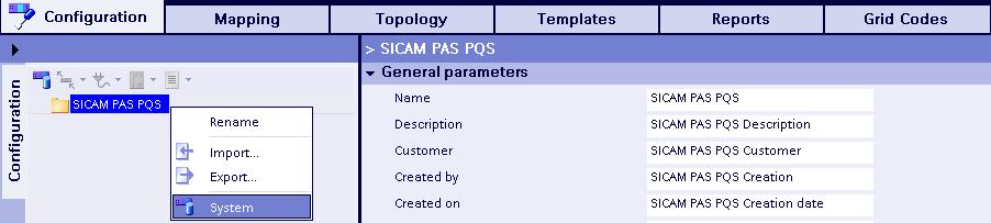
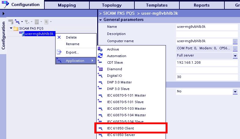
28 FASE_Workflow_Descriprion_ docx Page: 28 / Creation of SICAM PAS project Create a new PAS project. Create a system. Insert an IEC Client application. 28
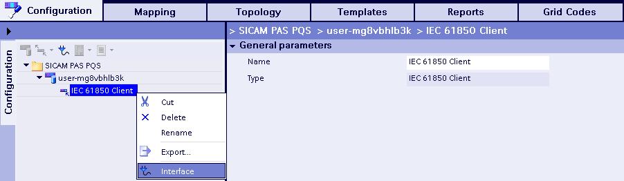
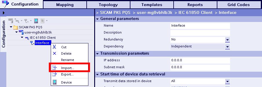
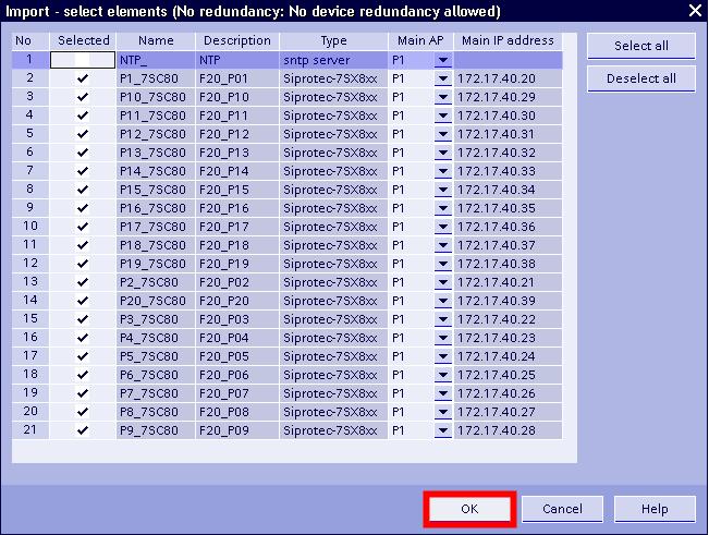
29 FASE_Workflow_Descriprion_ docx Page: 29 / 51 Insert a new interface under this application. Import the SCD file, which you exported by DIGSI. 29
,")
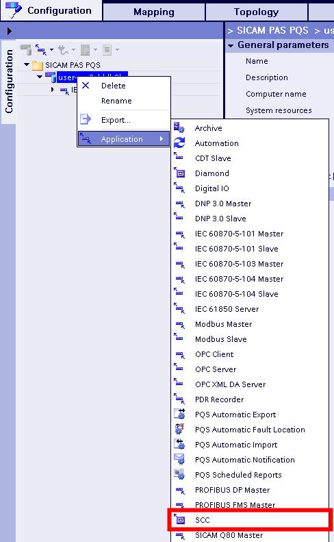
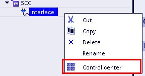
30 FASE_Workflow_Descriprion_ docx Page: 30 / 51 Create an application for HMI (SCC), interface and control center. 30

31 FASE_Workflow_Descriprion_ docx Page: 31 / 51 31

.")
 and STM_IND (DP) for command and feed back for Sequence Test Mode.")
 and SIM_IND (DP) for command and feed back for Simulation Mode.")
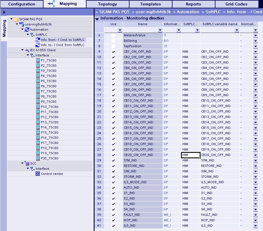
32 FASE_Workflow_Descriprion_ docx Page: 32 / 51 Create an application for automation, Soft PLC and devices Info. from - / Cmd. to SoftPLC and Info. to - / Cmd. from SoftPLC. Go to Templates and create the commands and indications for SoftPLC, which you will use in the HMI (DC Pulse Double Command, DP Double Point Indication, SE_AI Set Point Integer Command, ME_I Measurand Integer). - CBx_ON_OFF_CMD (DC) and CBx_ON_OFF_IND (DP) for command and feed back for switches P1 to P20. - STM_MODE (DC) and STM_IND (DP) for command and feed back for Sequence Test Mode. - RESTORE_MODE (DC) and RESTORE_IND (DP) for command and feed back for Restoration Mode. - SIM_MODE (DC) and SIM_IND (DP) for command and feed back for Simulation Mode. - STORM_MODE (DC) and STORM_IND (DP) for command and feed back for Simulation Mode. - ILS_MODE (DC) and ILS_MODE_IND (DP) for command and feed back for Isolate Line Section Mode. - AUTO_MODE (DC) and AUTO_IND (DP) for command and feed back for Automatic Mode. - FAULT (SE_AI) and FAULT_IND (ME_I) for command and feed back for Fault on the section. - NOP (SE_AI) and NOP_IND (ME_I) for command and feed back for Normally Open Point (NOP). 32
 and ILS_IND (ME_I) for command and feed back for number of Isolate Line Section.")
33 FASE_Workflow_Descriprion_ docx Page: 33 / 51 - ILS (SE_AI) and ILS_IND (ME_I) for command and feed back for number of Isolate Line Section. - Sx _CMD (DC) and Sx _IND (DP) for command and feed back for sources S1 to S4. 33

34 FASE_Workflow_Descriprion_ docx Page: 34 / 51 Go to Mapping and map all newly created information to Use. 34
35 FASE_Workflow_Descriprion_ docx Page: 35 / 51 35

36 FASE_Workflow_Descriprion_ docx Page: 36 / 51 Go to Topology, create a folder HMI and move all HMI commands and indications into this folder. 36

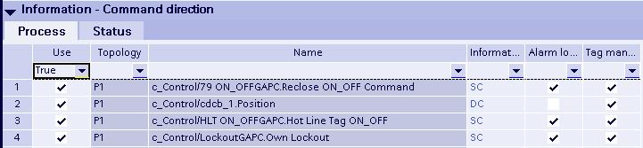
37 FASE_Workflow_Descriprion_ docx Page: 37 / 51 Go to the device folder in the Mapping and map following indications and commands to Use for device P1. - Control/79 ON_OFFGAPC.Reclose ON_OFF Command - Control/cdcb_1.Position - Control/CenSolGGIO1.Inrush Current Ph_Gnd - Control/cdhltGGIO1.Hot Line Tag ON goose - Control/fcLOGGIO1.Own Lockout goose - Control/HLT ON_OFFGAPC.Hot Line Tag ON_OFF - Control/LockoutGAPC.Own Lockout - Control/stownSGGIO1.Own Source Status is ON - Control/stownSGGIO2.Own Source Status is OFF - Measurement/Op meas value.i.phsa - Measurement/Op meas value.i.phsb - Measurement/Op meas value.i.phsc - Measurement/Op meas value.f - Measurement/sym comp value.current.c1 - Measurement/sym comp value.current.c2 - Measurement/sym comp value.current.c3 - Protection/50 General.Pickup - c_control/cdcb_1.position - c_control/79 ON_OFFGAPC.Reclose ON_OFF Command - c_control/hlt ON_OFFGAPC.Hot Line Tag ON_OFF - c_control/lockoutgapc.own Lockout 37


38 FASE_Workflow_Descriprion_ docx Page: 38 / 51 To copy the mapping information to another devices use mapping export function in the SICAM PAS. For this export the mapping information from the device P1. Change to configuration view and go to the IEC61850 interface. 38


, so you can use Tag")
39 FASE_Workflow_Descriprion_ docx Page: 39 / 51 Select all devices, which should get the same mapping information. The file with mapping information will also be available in the sharenet. After the mapping of necessary information create the topology for HMI tags. For each device create the folder (P1-P20), so you can use Tag Prefix function in the SICAM SCC. Move all information from SICAM PAS PQS folder to the correspondent folders. 39

40 FASE_Workflow_Descriprion_ docx Page: 40 / 51 Go to the Mapping and Info. to - / Cmd. from SoftPLC and map device information and command for using in SoftPLC. - Control/cdcb_1.Position - Control/fcLOGGIO1.Own Lockout goose - Control/CenSolGGIO1.Inrush Current Ph_Gnd - Control/cdhltGGIO1.Hot Line Tag ON goose - c_control/cdcb_1.position For devices on sources the source status information should be also mapped. - Control/stownSGGIO1.Own Source Status is ON - Control/stownSGGIO2.Own Source Status is OFF 40


41 FASE_Workflow_Descriprion_ docx Page: 41 / 51 Map all required information and commands to the SICAM Control Center (SCC). These are all information in the folders P1 to P20 and HMI. 41


42 FASE_Workflow_Descriprion_ docx Page: 42 / 51 Replace the SCC variable names with names from Topology. Open the SoftPLC application. 42


43 FASE_Workflow_Descriprion_ docx Page: 43 / 51 Import all logic files, which have been generation by FASE. - F20_DEVICE.ST - F20_EXEC_STEP.ST - F20_GLOBAL.POE - F20_HMI.ST - F20_LOGIC.ST - F20_SEQSTEPS_1.ST - F20_SEQSTEPS_2.ST - F20_Types.TYP After importing open each file and click on Check. 43


44 FASE_Workflow_Descriprion_ docx Page: 44 / 51 After that all files should appear in the project folder and can be inserted into the new CFC chart. Create a new CFC chart. 44

 and connect the information you mapped to the SoftPLC (see picture")
45 FASE_Workflow_Descriprion_ docx Page: 45 / 51 Insert the DEVICE.ST block so many times you have nodes in your grid (P1 to P20). E.g. for 20 devices, which are using in your project, you should insert 20 blocks. Give the number to the block (1-20) and connect the information you mapped to the SoftPLC (see picture below). Insert the HMI.ST block and connect it with commands and indications, how it shown in the pictures below. 45


46 FASE_Workflow_Descriprion_ docx Page: 46 / 51 This block receives the commands from SCC to control the modes and switching devices and gives the feedback information back to the SCC. Insert the LOGIC.ST block and connect it with commands and indications, how it shown in the pictures below. 46


47 FASE_Workflow_Descriprion_ docx Page: 47 / 51 This block receives the status of all sources and send commands to the real devices in order to run the defined sequences for isolation, restoration, manually control etc. All other blocks should not be inserted by user and are responsible for internal functionality. Compile the Soft PLC logic and, if no errors or warnings were appeared, close it. Go to Mapping and map commands and information for using it in SCC. Monitoring direction for information from each device 47

48 FASE_Workflow_Descriprion_ docx Page: 48 / 51 Monitoring direction for logical information Command direction for commands to each device 48
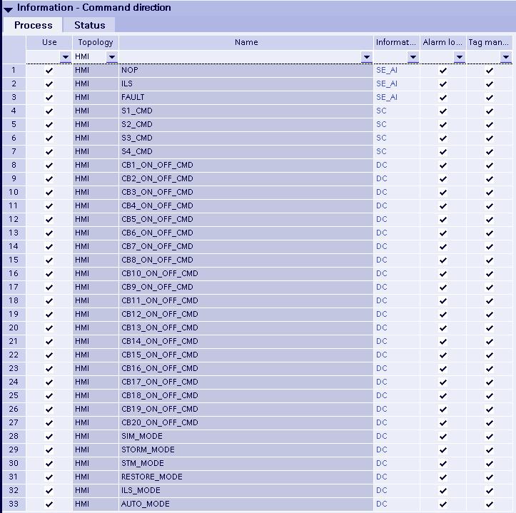
49 FASE_Workflow_Descriprion_ docx Page: 49 / 51 Command direction for logical commands 49


50 FASE_Workflow_Descriprion_ docx Page: 50 / 51 In Mapping replace the variable names for the SCC with the topological names. In Configuration export the PXD file for importing in SICAM SCC. 50

51 FASE_Workflow_Descriprion_ docx Page: 51 / Creation of SICAM SCC project For saving of configuration time you can take the example SCC project for the topology consisting of 20 devices, which has been tested in Nuremberg or only the picture with switching devices and devices information shown below. Create new driver connection to the SICAM PAS and import the PXD file, which you exported in the PAS project. After that adapt the picture to your own topology and check the tag connections for all objects located in the picture. 51
SIPROTEC 5 Application Note
 www.siemens.com/protection SIPROTEC 5 Application Note SIP5-APN-014: Answers for infrastructure and cities. SIPROTEC 5 - Application: SIP5-APN-014 Mixed configurations of SIPROTEC 4 and SIPROTEC 5 Content
SIPROTEC 5 Application Note
 www.siemens.com/protection SIPROTEC 5 Application Note SIP5-APN-007: with IEC 61850 Answers for infrastructure and cities. SIPROTEC 5 - Application: SIP5-APN-007 Interconnection of SIPROTEC 5 devices to
Communication in Substations with IEC Simple Communication Test with IEC Johannes Bruss, Siemens AG, E D EA PRO LM Siemens AG 2008
 Communication in Substations with IEC 61850 Simple Communication Test with IEC61850 Johannes Bruss, Siemens AG, E D EA PRO LM As a first example, it has to be checked in a simple way that the communication
Blueprint Data Center
 Systems and Applications for Data Center Siemens Industy 1. Overview / Purpose In EM EA the datacenter market is seen as one of the fastest growing of the energy businesses. This blueprint is designed
SIPROTEC 7SC80 Feeder Protection and Automation Answers for infrastructure and cities.
 www.siemens.com/protection SIPROTEC 7SC80 Feeder Protection and Automation Answers for infrastructure and cities. designed for feeder automation applications This solution allows very fast fault detection
Substation to substation (ss2ss) GOOSE exchange for critical relay operations
 GOOSE exchange for critical relay operations") CIGRÉ Canada 21, rue d Artois, F-75008 PARIS (CIGRE-130) Conference on Power Systems http : //www.cigre.org Vancouver, October 17-19, 2010 Substation to substation (ss2ss) GOOSE exchange for critical relay
CIGRÉ Canada 21, rue d Artois, F-75008 PARIS (CIGRE-130) Conference on Power Systems http : //www.cigre.org Vancouver, October 17-19, 2010 Substation to substation (ss2ss) GOOSE exchange for critical relay
The System for Power Automation
 Basics 1 Tasks and solution The System for Automation The Tasks: Scalable system for Distributed process connection Process visualization Interface to control centre The Solution: Automation System PTD-SE-A2/
SIPROTEC 5 V7.8 Protection, automation and monitoring for digital substations
 SIPROTEC 5 V7.8 Protection, automation and monitoring for digital substations siemens.com/siprotec5 SIPROTEC 5 Table of content Introduction New functions of V7.8 SIPROTEC 5 - the core of Digital Substation
SIPROTEC 5 Application Note
 s www.siemens.com/protection SIPROTEC 5 Application Note SIP5-APN-013: devices Answers for infrastructure and cities. SIPROTEC 5 - Application: devices Content 1 Application: devices 3 1.1 Summary 3 1.2
Recloser Controller for feeder protection and automation siemens.com/distribution-automation
 SIPROTEC 7SC80 Control Controller for feeder protection and automation siemens.com/distribution-automation SIPROTEC 7SC80 Control Designed for feeder automation applications This solution allows very fast
SIPROTEC 5 Application Note
 www.siemens.com/protection SIPROTEC 5 Application Note SIP5-APN-011: Answers for infrastructure and cities. SIPROTEC 5 - Application: SIP5-APN-001 Content 1 Application: 3 1.1 Summary 3 1.2 Application
SIPROTEC 5 Application Note
 www.siemens.com/protection SIPROTEC 5 Application Note SIP5-APN-001: Properties and Functional Structure Answers for infrastructure and cities SIPROTEC 5 Properties SIPROTEC 5 - Application: SIP5-APN-001
SIPROTEC 7SC805. Merging Unit for conventional instrument transformer. Products for digital substations.
 Products for digital substations SIPROTEC 7SC805 Merging Unit for conventional instrument transformer Integrated PRP, HSR www.siemens.com/processbus built to create digital substations based on IEC 61850-9-2
Dan Murray, Siemens Energy Management Division
 Design and Implementation of a Communication Network to Support Real-time Distribution Feeder Automation, SCADA Integration and Backhaul of Substation and Metering Data Dan Murray, Siemens Energy Management
SIPROTEC 5 Application. SIP5-APN-027: Change of switching authority via function keys.
 www.siemens.com/protection SIP5-APN-027: Answers for infrastructure and cities. SIPROTEC 5 - Application: Change of switching authority via function keys Content: 1 3 1.1 Introduction 3 1.2 Configuration
Digital Substation Unrestricted Siemens AG 2017 siemens.com/digital-substation
 Digital Substation A Substation Why Should We Make It Digital? Adopt new business models Time to operation Quality assurance Business agility Avoid outages Investment security Ensuring grid availability
Comprehensive Cyber Security Features in SIPROTEC & SICAM. SIPROTEC Dag 11. Mei 2017
 Comprehensive Cyber Security Features in SIPROTEC & SICAM SIPROTEC Dag 11. Mei 2017 siemens.tld/keyword Changes to Substation Automation and Protection over Time Evolving Threat Landscape (tomorrow today...)
SIPROTEC Overcurrent Protection 7SJ80. Motor Protection 7SK80. Preface. Content. Data in the PROFINET IO Mapping 1. Standard Mapping
 Preface SIPROTEC Overcurrent Protection 7SJ80 Motor Protection 7SK80 Content Data in the PROFINET IO Mapping 1 Standard Mapping 3-1 2 Glossary Index Communication Module PROFINET IO Bus Mapping C53000-L1840-C362-1
Advanced Process Functions V2.0
 Advanced Process Functions V2.0 Engineering tool, function blocks and HMI library for material, parameter, storage location, job and archive management for the Process Control System SIMATIC PCS 7, enhanced
SICAM ertu Your Entry to Telecontrol Technology with Extended Functionality
 SICAM ertu Your Entry to Telecontrol Technology with Extended Functionality Power Transmission and Distribution The Comprehensive Solution SICAM ertu offers all you need for telecontrol, and plenty more
SIPROTEC 5 New features of V7.5
 SIPROTEC 5 New features of V7.5 siemens.com/siprotec5 New Features for SIPROTEC 5 Release 7.50 Feeder Protection Ground Fault Detection (Pulse Detection, Harmonic Detection) Automatic Load Shedding Vector
SIPROTEC 5 Application Note
 www.siemens.com/protection SIPROTEC 5 Application Note SIP5-APN-010: Answers for infrastructure and cities. SIPROTEC 5 - Application: SIP5-APN-010 SIPROTEC 5 Application Content 1 Application 3 1.1 Summary
Siemens AG All rights reserved.
 SICAM Substation ti Automation ti Smart Substation Automation Panels DC PW SUPPLY DC PW SUPPLY GPS ARBITER SCALANCE X324 MONITOR RSG2100 RSG416 MONITOR GE UR T60 MUX GARD8000 7UT633 7SL87 7SL87 RACK PC
Alexandre Oudalov, ABB Corporate Research, Santiago 2013 Symposium on Microgrids. New Technologies for Microgrid Protection
 Alexandre Oudalov, ABB Corporate Research, 2013-09-11 Santiago 2013 Symposium on Microgrids New Technologies for Microgrid Protection New technologies for microgrid protection Outline Introduction What?
SICAM Products and Solutions for Energy Automation
 SICAM Products and Solutions for Energy Automation Manfred Haslinger, Product Lifecycle Manager SICAM RTUs Josef Müllner, Product Lifecycle Manager SICAM TOOLBOX II siemens.at/future-of-energy SICAM Products
RELEASE NOTE. System Data Manager SDM600 SDM600 Ver. 1.2 Service Pack 2
 RELEASE NOTE System Data Manager SDM600 SDM600 Ver. 1.2 Service Pack 2 SDM600 Ver. 1.2 SP2 Release Note Introduction This Service Pack includes new features and corrections for functional issues in SDM600
User Manual.
 User Manual www.gridsoftware.com Table of Contents SCL Matrix Overview...4 1. Startup Screen...5 2. Ribbon...7 2.1. Home...8 2.2. Engineering Process...9 2.3. Add...10 2.4. Import/Export...11 3. Projects...12
Overview and Application
 IEC 61850 Overview and Application Who am I? Rich Hunt Market Development Leader GE Grid Solutions Over 25 years in the power systems industry At GE for 10 years (almost) Member of IEEE PSRC, U.S. Representative
SIPROTEC 5 Application Note
 www.siemens.com/protection SIPROTEC 5 Application Note SIP5-APN-012 : Control of Breaker-and-a-half diameters and double busbar configurations and use of Phasor Measurement Unit (PMU) Answers for infrastructure
SIPROTEC 5 Application Note
 www.siemens.com/protection SIPROTEC 5 Application Note SIP5-APN-020: Answers for infrastructure and cities. SIPROTEC 5 - Application: Content 1 Application: 3 1.1 Summary 3 1.2 General 3 1.3 Download PICS
SIPROTEC 5 Engineering Guide DIGSI 5
 Preface Open Source Software SIPROTEC 5 Engineering Guide DIGSI 5 V6.0 and higher Table of Contents DIGSI 5 Overview 1 Essential Steps during Engineering 2 Loading Configuration into SIPROTEC 5 Device
Protective Relays & SCADA Systems
 14 SWITCHGEAR Protective Relays & SCADA Systems SCADA Substation Automation SICAM PAS & PQ Analyzer SICAM PAS (Power Automation System) is a complete substation automation control and protection system
SICAM PAS V5.0 监控系统 6MD69.
 V5.0 监控系统 6MD69 www.siemens.com.cn/ea 2 Siemens SICAM 4.1.1 2004 V5.0 6MD9 2 3-4 SICAM 4.1.1 2004 5 6 7 8 9 10 11 Siemens SICAM 4.1.1 2004 3 ( ) PAS SICAM IED IEC61850 IEC60870 5 103 IEC60870 5 101 PROFIBUS
Siemens Industrial Spares
 s SIPROTEC 4 und SIPROTEC Compact State 12/16 Service Information Firmwareupdate Copyright Siemens AG 2015 Subject to technical alteration Siemens Aktiengesellschaft Siemens Industrial Spares 1 Copyright
IEC61850 communication solution WinCC Channel
 IEC61850 communication solution WinCC Channel Documentation Date: 15.04.2015 Version: 2.03 IEC 61850 communication solution Page 1 of 33 Change history Datum Version Author Changes 19.11.2010 00.1 Mr.
Block Library Motor Starter SIRIUS for SIMATIC PCS 7
 Industrial Controls Block Library Motor Starter SIRIUS for SIMATIC PCS 7 SIRIUS Motor Starter PCS 7 Library V7.1+SP2 / SIRIUS Motor Starter PCS 7 Library V8 Migration 8.0+SP1 Getting Started Edition 08/2013
Perfect protection smallest space
 www.siemens.com/energy/protection Perfect protection smallest space The SIPROTEC Compact device range redefines protection technology Answers for energy. SIPROTEC Compact is the ideal solution for almost
IEC in the ELVAC products
 www.elvac.eu IEC 61850 in the ELVAC products Jan Slezák IEC 61850 in the ELVAC products IEC 61850 in the Mikrodispecink SCADA Used mainly as an HMI (e.g. CEZ substations Havířov and Kojetín) Support through
Grid Automation Controller COM600 How it fits into the Smart Grid?
 ABB Oy Distribution Automation Grid Automation Controller How it fits into the Smart Grid? May 27, 2014 Slide 1 1MRS756763 E Content Technical Presentation May 27, 2014 Slide 2 Description Grid Automation
Installing the application involves several steps. Note that you must install QuickBooks on your computer prior to installing this application.
 CCRQLABEL OVERVIEW This is an overview (summary) of the CCRQLabel 4.x label printing product. Full documentation is under development INSTALLING CCRQLABEL This document provides a quick review of how to
Jehanpour Ranjkesh, Integrator Partner Seminar 2012 Station level product news Automation Controller COM600
 Jehanpour Ranjkesh, Integrator Partner Seminar 2012 Station level product news Automation Controller COM600 Contents COM600 Product Overview Business Overview Product News Overview June 12-14, 2012 Slide
The complete application guide to specifying a Smart-Gear power distribution solution (PDS) E50001-F710-A123-V1-4A00. Answers for energy.
 E50001-F710-A123-V1-4A00. Answers for energy.") The complete application guide to specifying a Smart-Gear power distribution solution (PDS) E50001-F710-A123-V1-4A00 Answers for energy. Smart-Gear power distribution solution (PDS) Siemens, a world leader
The complete application guide to specifying a Smart-Gear power distribution solution (PDS) E50001-F710-A123-V1-4A00 Answers for energy. Smart-Gear power distribution solution (PDS) Siemens, a world leader
View the most recent product information online
 SIMATIC S7-PLCSIM V5.4 including SP8 Simulation Software Readme Notes on Installation and Use These notes should be considered more up-to-date than the information in the S7- PLCSIM and S7ProSim online
Process Control System PCS 7 V7.0. Getting Started First Steps Documentation November 2006
 Process Control System PCS 7 V7.0 Getting Started First Steps Documentation November 2006 Qualified Personnel Only qualified personnel should be allowed to install and work on this equipment. Qualified
Industrial Controls. SIMOCODE pro SIMOCODE pro PCS 7 Library. Preface. Security information. Product specific security. information.
 Industrial Controls SIMOCODE pro Preface 1 Product specific security Security information 2 information 3 Introduction 4 5 References 6 List of Abbreviations 7 10/2018 A5E36558134002A/RS-AB/002 Legal information
ActionWise. Software SCADA/ADMS. Configuration and Operation Manual. Version 2 Rev 2. Spin Engenharia de Automação Ltda. Brasilia, March 2017
 ActionWise Software SCADA/ADMS Configuration and Operation Manual Version 2 Rev 2 Spin Engenharia de Automação Ltda. Brasilia, March 2017 SPIN Engenharia de Automação Ltda. SCLN 212 Bloc D - Room 101 PO
SIPROTEC 5 Application Note. Breaker-and-a-half solutions. SIP5-APN-002, Edition 2.
 -and-a-half solutions SIP5-APN-002, Edition 2 www.siemens.com/protection SIPROTEC 5 Application Note -and-a half solutions SIP5-APN-002, Edition 2 -and-a-half solution Content 1 -and-a-half solutions 3
SICAM DC - A new Generation of Smart Meter Data Concentrator Answers for infrastructure and cities.
 Siemens Smart Grid Products - A new Generation of Smart Meter Data Concentrator Answers for infrastructure and cities. Smart Metering an integral Part of Smart Grids The Challenges. The Contribution of
Display of SINAMICS Fault Messages in WinCC V7.4
 Application Example 03/2017 Display of SINAMICS Fault Messages in WinCC V7.4 SINAMICS G120, WinCC V7.4 https://support.industry.siemens.com/cs/ww/de/view/109744939 Warranty and Liability Warranty and Liability
End User SharePoint 2010 Videos List
 End User SharePoint 2010 Videos List Screencast Name Number Abstract Category A subsite (or simply referred to as site) is created as an interface for hosting pages, lists, libraries and web parts. Creating
Pharos Designer 2. Copyright Pharos Architectural Controls (15/1/2015)
") Pharos Designer 2 Welcome Welcome to Pharos Designer 2. We are delighted to introduce you to an entirely new version of the Pharos Designer software that picks up where the venerable and much- loved version
Pharos Designer 2 Welcome Welcome to Pharos Designer 2. We are delighted to introduce you to an entirely new version of the Pharos Designer software that picks up where the venerable and much- loved version
Products for digital substations SIPROTEC 6MU805. Merging Unit for conventional instrument transformer. Integrated PRP, HSR. siemens.
 Products for digital substations SIPROTEC 6MU805 Merging Unit for conventional instrument transformer Integrated PRP, HSR siemens.com/processbus built to create digital substations based on IEC 61850-9-2
1 What's new in SIMATIC imap STEP 7 AddOn?
 Component Based Automation SIMATIC imap STEP 7 AddOn V3.0 incl. SP1 to SP5 Notes on installation and use Table of contents 1 What's new in SIMATIC imap STEP 7 AddOn? 2 Installation notes 3 Compatibility
Energy Automation Catalog SICAM
 SICAM PAS Software 6MD9 Energy Automation Catalog SICAM 4.1.2 2007 Power Transmission and Distribution SICAM PAS Software 6MD9 Catalog SICAM 4.1.2 2007 Supersedes: Katalog SICAM 4.1.2 2006 Contents System
DISCOVER CONTROL IDE
 DISCOVER CONTROL IDE Visual Logic Programmer... 3 Main window... 3 Logic parameters... 3 Functional blocks... 4 Inputs... 4 Outputs... 4 Constants... 5 Variables... 5 Creating program... 5 Emulator...
L01 - Effective Design Methods for Integrating Safety Using Logix Controllers. For Classroom Use Only!
 L01 - Effective Design Methods for Integrating Safety Using Logix Controllers For Classroom Use Only! Important User Information This documentation, whether, illustrative, printed, online or electronic
Secure energy supply. Energy Automation for the Chemical and Pharmaceutical Industry
 Secure energy supply for the Chemical and Pharmaceutical Industry Electrical Power Supply for the Chem&Pharma Industry Characteristics Has an effect directly on the core business Availability clearly measurable
Cyber Security in the Digital Substation and Beyond. Energy Management > Energy Automation
 Cyber Security in the Digital Substation and Beyond Energy Management > Energy Automation siemens.com/gridsecurity Cyber Security Offerings From Siemens Energy Management Integrated Security in our products
Plant Automation Accelerator 2.0
 Security information 1 Preface 2 Objectives and performance scope of the data interface 3 Operating Manual Overview of data exchange with PCS 7 4 Requirements in PCS 7 5 Preparations 6 Management of control
Substation Automation
 Substation Automation Page SICAM PAS Substation Automation System /3 SIPROTEC 4 6MD61 I/O-Box /11 SIPROTEC 4 6MD63 Bay Control Unit /19 SIPROTEC 4 6MD66 High-Voltage Bay Control Unit /21 /2 Substation
Welcome to the safety functions configuration training module for ACS880 Cabinet-built industrial drives.
 Welcome to the safety functions configuration training module for ACS880 Cabinet-built industrial drives. 1 After viewing this presentation you will be able to describe: The functionality of cabinet-built
Peter Overgaauw Pascal Stijns 27 Oct 2016 EXPERION PKS CONTROLS ELECTRICAL SYSTEMS TOO!
 Peter Overgaauw Pascal Stijns 27 Oct 2016 EXPERION PKS CONTROLS ELECTRICAL SYSTEMS TOO! Abstract Gain a basic understanding of an electrical control management system Exposure to a number of technology
IEDScout. Versatile software tool for working with IEC devices
 IEDScout Versatile software tool for working with IEC 61850 devices One software tool for working with all IEC 61850 IEDs Examine IEC 61850 devices IEDScout is an ideal tool for protection and substation
RELEASE NOTE. System Data Manager SDM600 SDM600 Ver. 1.2 Feature Pack 1
 RELEASE NOTE System Data Manager SDM600 SDM600 Ver. 1.2 Feature Pack 1 4 SDM600 VER. 1.2 FP1 RELEASE NOTE SDM600 Ver. 1.2 FP1 Release Note Introduction This Feature Pack includes new features and corrections
APPLICATION NOTES. Advanced Graphical Interface - AGI Internal PLC (CODESYS V3) SHENDONG
 SHENDONG") APPLICATION NOTES Advanced Graphical Interface - AGI Internal PLC (CODESYS V3) SHENDONG CODESYS V3 logic running on AGI 300/400 series product Support of Modbus/TCP and RTU communication Use of remote
APPLICATION NOTES Advanced Graphical Interface - AGI Internal PLC (CODESYS V3) SHENDONG CODESYS V3 logic running on AGI 300/400 series product Support of Modbus/TCP and RTU communication Use of remote
INTERFACING A PANELVIEW 660 TO A CONTROL LOGIX 5550 CONTROLLER. PA Gouws, TA Harrison, PC Pelser
 INTERFACING A PANELVIEW 660 TO A CONTROL LOGIX 5550 CONTROLLER PA Gouws, TA Harrison, PC Pelser Iscor Flat Steel Products, Vanderbijlpark Steel, Technical Training This paper describes how an Allen Bradley
Information About the Getting Started PCS 7 - First Steps Documentation
 Preface Information About the Getting Started with PCS 7; The First Steps documentation uses a simple sample project to show you the fundamental procedures and the interaction of the software components
Next step in IEC 61850: Large applications and process bus applications José Roberto Moreira Rodrigues Clemens Hoga
 Next step in IEC 61850: Large applications and process bus applications José Roberto Moreira Rodrigues Clemens Hoga Agenda Process bus application Large Applications IEC 61850 Overview *standardization
Importing non-numerical character data
 BioNumerics Tutorial: Importing non-numerical character data 1 Aims This tutorial shows how to import non-numerical data in a BioNumerics database and link the data to a character type experiment. It illustrates
Accord Builder. User Guide
 User Guide Document: V 3.6 User Guide R01 V3.6 User Guide R01 Page 1 of 110 Table of Contents 1 Introduction... 7 2 General Summary and Definitions... 8 2.1 Accord Platform and Plant... 8 2.2 PLC Control
IDVisor Smart ID Scanner. User s Guide. Age Verification machine
 IDVisor Smart ID Scanner User s Guide Age Verification machine IDVisor Smart User s Guide Page 2 of 18 Copyright Copyright 2002-2016 TokenWorks, Inc. Printed in the USA Information in this document is
STEP 7. Function. Page 1791 Mar 2008 Siemens ITS
 STEP 7 Function STEP 7 blocks STEP 7 files all user-written programs and all the data required by those programs in blocks. The possibility of calling other blocks within one block, as though they were
*** If you have a Quick Designer project skip this section ***
 Application Note #1232: PROFIBUS Migration to GP-Pro EX Introduction GP-Pro PB3 and Quick Designer projects can be converted into GP-Pro EX projects using a project converter. However additional steps
CFC. Special functions from SIMATIC S7 CFC V7.0 SP1 onwards
 CFC Function Function expansions from SIMATIC S7 CFC V7.1 onwards Forcing of values of an interconnected input: by means of the "Force functionality", interconnected block inputs can be forced to use the
RELEASE NOTE. Integrated Engineering Tool IET600 Ver. 5.3 Feature Pack 3
 RELEASE NOTE Integrated Engineering Tool IET600 Ver. 5.3 Feature Pack 3 2 IET600 VER. 5.3 FP3 RELEASE NOTE IET600 Ver. 5.3 FP3 Release Note Dear Reader, We are pleased to announce the release of IET600
User Guide. Kronodoc Kronodoc Oy. Intelligent methods for process improvement and project execution
 User Guide Kronodoc 3.0 Intelligent methods for process improvement and project execution 2003 Kronodoc Oy 2 Table of Contents 1 User Guide 5 2 Information Structure in Kronodoc 6 3 Entering and Exiting
SIPROTEC 3/4 central operation via Ethernet Serial-Hub
 L2 402,1A L3 402,1A L2 402,1A L3 402,1A Power Transmission and Distribution SIPROTEC 3/4 central operation via Ethernet Serial-Hub General The serial hub and the associated configuration software may be
Secure energy supply. Energy Automation for the Semiconductor Industry
 Secure energy supply for the Semiconductor Industry (EA) Integral Part of Energy Sector Energy Sector Oil & Gas Fossil Power Generation Renewable Energy Service Rotating Equipment Power Transmission Power
Easily configurable HMI system for power automation siemens.com/sicam
 SICAM SCC Easily configurable HMI system for power automation siemens.com/sicam Small components big prospects: Your SICAM SCC station control Power grid operation is becoming more and more dynamic. To
Integrating IEC & IEEE 1815 (DNP3)
") Integrating IEC 61850 & IEEE 1815 (DNP3) Andrew West Regional Technical Director, SUBNET Solutions, Inc. SUMMARY North America has a mature electric power grid. The majority of grid automation changes
Integrating IEC 61850 & IEEE 1815 (DNP3) Andrew West Regional Technical Director, SUBNET Solutions, Inc. SUMMARY North America has a mature electric power grid. The majority of grid automation changes
Commissioning the 9400 Highline TA CiA402 with EtherCAT and Beckhoff NC
 Commissioning the 9400 Highline TA CiA402 with EtherCAT and Beckhoff NC Contents 1. Preface/aim of the Application Report...2 2. Introduction...3 2.1. General information on EtherCAT...3 2.2. General information
TxA SoftControl - FnIO-S NA-9173 / NA-9473 Modbus RTU KI
 TxA SoftControl - FnIO-S NA-9173 / NA-9473 Modbus RTU KI00302 2012-11 1 Function and area of use The terminal TxA SoftControl communicates with a remote I/O (Crevis FnIO-S Serie) in a Modbus RTU (serial)
Making the decision to switch from PLC to PC-based Control has gotten even easier with the introduction of MachineLogic Control Software.
 CTC Parker Automation MachineLogic and MachinePoint TM I/O A complete systems solution for open machine control MachineLogic Control Software, combined with CTC s new MachinePoint I/O products, gives you
Profibus Getting Started User's Manual
 www.infoplc.net Profibus Getting Started User's Manual Version: 1.00 (July 2006) Model No.: MAPBGETST-ENG We reserve the right to change the contents of this manual without warning. The information contained
Operator Station (V8.0) SIMATIC. Process Control System PCS 7 Operator Station (V8.0) Preface 1. The PCS 7 Operator Station
 SIMATIC. Process Control System PCS 7 Operator Station (V8.0) Preface 1. The PCS 7 Operator Station") SIMATIC Process Control System PCS 7 Configuration Manual Preface 1 The PCS 7 Operator Station 2 Introduction to OS configuration 3 Setting languages 4 Configuring OS data in SIMATIC Manager 5 Configuring
SIMATIC Process Control System PCS 7 Configuration Manual Preface 1 The PCS 7 Operator Station 2 Introduction to OS configuration 3 Setting languages 4 Configuring OS data in SIMATIC Manager 5 Configuring
Siemens Controls. SIPROTEC 5 Communication Protocols. Preface. Table of Contents. Communication Modules 1 IEC DNP3 3 IEC
 Preface SIPROTEC 5 Communication Protocols V7.50 and higher Manual Table of Contents Communication Modules 1 IEC 61850 2 DNP3 3 IEC 60870-5-104 4 Modbus TCP 5 IEC 60870-5-103 6 PROFINET IO 7 Protection
DLP GUIDE
 www.safetica.com DLP GUIDE Content Introduction to context DLP protecting data with Safetica... 3 How does Safetica protect data?... 3 Exercise: Use-cases for most common scenarios... 4 Protecting data
Siprotec 7ST61 / 7ST63
 Siprotec / Numerical overhead contact line protection for AC traction power supply siemens.de/rail-electrification The numerical overhead contact line protection relay Siprotec / is a selective and quick
EDMtruePLM True Product Lifecycle Management User s Guide for Version 2.2
 EDMtruePLM True Product Lifecycle Management User s Guide for Version 2.2 Proprietary notice Information in this publication is subject to change without notice. No part of this publication may be distributed
User Manual Version: Date: JAN 2016
 User Manual Version: 7.0.0 Date: JAN 2016 The graphical user interface (GUI) of myscada system is based on standard web pages, meaning that any web browser installed on your computer, such as MS Internet
Merbon Menu Reader. Installation and setup V1.0 1
 Merbon Menu Reader Installation and setup V1.0 1 Contents Application description...2 Installation...2 ios...2 Android...2 Embedded Linux...2 Editing a value...5 Date and time...6 Analogue value...6 Digital
Zelio Logic 2 Online Help
 Page 1 of 234 Zelio Logic 2 Online Help Overview of the Zelio Soft 2 Software At a Glance Subject of this Section This section provides an overview of the Zelio Soft 2 software. What's in this Part? This
Perfect protection smallest space
 www.siemens.com/siprotec Perfect protection smallest space The SIPROTEC Compact device range redefines protection technology Answers for infrastructure and cities. SIPROTEC Compact is the ideal solution
Call: Crystal Report Course Content:35-40hours Course Outline
 Crystal Report Course Content:35-40hours Course Outline Introduction Of Crystal Report & It s Benefit s Designing Reports Defining the Purpose Planning the Layout Examples of Reports Choosing Data Laying
Printing - tips on printing
 Printing - tips on printing TIPS to help you print School PUPIL TRACKER Online pages How to print a page Print this page button the Print this page button (which can be found in the upper left corner of
MotionView Configuration and Programming Software USER S MANUAL
 MotionView Configuration and Programming Software USER S MANUAL IM94MV01C Table of Contents 1 MotionView Software Overview......................................... 3 1.1 Installation and Package Revision.................................................
SIMATIC. Process Control System PCS 7 First Steps (V7.1) Preface 1. Creating the PCS 7 Project 2. Configuring the hardware and networks
 Preface 1. Creating the PCS 7 Project 2. Configuring the hardware and networks") SIMATIC Process Control System PCS SIMATIC Process Control System PCS 7 Getting Started Preface 1 Creating the PCS 7 Project 2 Configuring the hardware and networks 3 Configuring the process tags and the
SIMATIC Process Control System PCS SIMATIC Process Control System PCS 7 Getting Started Preface 1 Creating the PCS 7 Project 2 Configuring the hardware and networks 3 Configuring the process tags and the
USER MANUAL. Version October 2014
 USER MANUAL Version 3.2 - October 2014 USER MANUAL Xsquare 3.2 Copyright EVS Broadcast Equipment SA Copyright 2012-2014. All rights reserved. Disclaimer The information in this manual is furnished for
for Q-CHECKER Text version 15-Feb-16 4:49 PM
 Q-MONITOR 5.4.X FOR V5 for Q-CHECKER USERS GUIDE Text version 15-Feb-16 4:49 PM Orientation Symbols used in the manual For better orientation in the manual the following symbols are used: Warning symbol
Product Bulletin. SGConfig Configuration Tool v9.0. GE Grid Solutions. Release Notification of SGConfig 9.0. Before Installation
 GE Grid Solutions SGConfig Configuration Tool v9.0 Product Bulletin Date: August 11, 2016 Classification: GE Information Release Notification of SGConfig 9.0 SGConfig is a PC software-based user interface