JetMax Throttle Installation Instructions
|
|
|
- William Francis
- 6 years ago
- Views:
Transcription

1 JetMax Throttle Installation Instructions 1
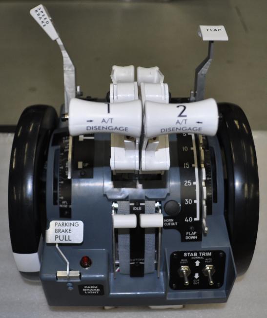
2 The JetMax 737 Throttle unit is designed to bring our customers a highly realistic looking device that covers all the basic requirements needed! Features Include: -USB Plug and Play (No Drivers Required!) - Functional Twin Thrust Levers - Reverse Thrust Handles - TOGA Switches - A/T Disconnect Switches - Flap Handle - Speed Brake Handle - Fuel Cut-off Levers - Parking Brake Lever and Light - Realistic Representation Trim Wheels (non-rotating) The JetMax 737 Throttle unit is the perfect match for the SSTD, Desktop use or in your full scale project. The JetMax 737TQ arrives fully assembled and requires no custom drivers. Please Note: *The 737TQ is not a motorized device. Trim Control is achieved via your Yoke setup and EICAS display. *Requires calibration and switch assignments in FSUIPC. *Extra wire and connector for Optional Steering Tiller Mechanism Basic knowledge of FSX and FSUIPC is required (FSUIPC Manual is recommended reading) *The JetMax product is not designed for commercial use. Any such use would void any warranties stated or implied. 2
3 Important Information regarding the JetMax throttle: The JetMax Throttle is a plug and play device using a custom game controller. This controller can be accessed through the Windows Game Controller. There are calibration instructions that need to be followed as outlined in this manual. Also some switch offsets assigned via FSUIPC. A registered version of Peter Dowson s FSUIPC is required and available here: FSUIPC Settings are accessed through Flight Simulator. Some Flight Simulator settings need to be deleted. *Please refer to the FSUIPC Manual for assignments and calibration. Some are covered in this manual but a detailed listing of all FSUIPC assignments and instructions are available in the FSUIPC Manual located here: C:\Your Location of FS\Modules\FSUIPC Documents 3
4 4

5 JetMax Throttle Cables and Harness The JetMax Throttle comes with a USB cable and also a harness (with Red/White/Black wires) for the Optional Steering Tiller. The Steering Tiller comes with a harness and plug to connect to the Throttle connector and plug. Remove the attached jumper and connect the Steering Tiller. Instructions for adding the Steering Tiller are in this manual. If you do not have the Optional Steering Tiller you must leave the jumper attached to the Throttle harness. Throttle harness for Optional Steering Tiller Jumper 5
6 The JetMax Throttle will work with the following Avionics Suites: Aerosytems FS9 /FSX / Prepar3d (limited functionality, some switches require an Avionics Suite) ifly (Requires iflytofsuipc) PMDG Requires: PMDG Module v1.1.zip Project Magenta ProSim Sim-Avionics More to follow... Configuration is dependant on the offsets used by each program. Some experimentation may be required and involves some trail and error. Some configurations may require questions in the above mentioned Forums. *** This JetMax manual is only a basic guide.*** 6

7 JetMax 737 Throttle Game Controller Location of the Game Controller below: Control Panel\Hardware and Sound\Devices and Printers Accessing the JetMax Throttle Game Controller allows you to test all the functions of the Game Controller via Windows. *Windows 7 shown above 7

8 Right-click on the JetMax controller Select Game Controller Settings Select Properties 8

9 Listing of potentiometers and switches: Slider Engine 1 X-Rotation Spoiler Y-Rotation Engine 2 Z-Rotation Flaps Dial Steering Tiller (optional) 1. Parking Brake 2. ENG 1 TOGA 3. ENG 2 A/T Disc 4. ENG 2 TOGA 5. ENG 2 Reverser 6. ENG 1 A/T Disc 7. ENG 1 Reverser 8. ENG 2 Fuel Cut-off 9. ENG 1 Fuel Cut-off 9
10 How to start the calibration and switch assignments 1. Whenever a game controller is plugged into Windows for the first time in FS9, FSX or Prepar3D the default settings are applied. You need to remove these settings from FS via OPTIONS / CONTROLS and select the Game Controller (in this case JetMax 737 Controller). Go to Joystick Axes and scroll down the Axis list. Select each Axis and click on Delete Joystick Assignment. Do this for every Axis listed under the JetMax 737 Controller. NOTE: if you have other USB devices (Pedals, yoke etc) they will show in the Joystick Type in the drop down menu. Only do the JetMax 737 Controller. See Figure 5 *Extra wire and connector for Optional Steering Tiller Mechanism *Please refer to the FSUIPC Manual for complete instructions and detailed information related to FSUIPC. *** This JetMax manual is only a basic guide.*** 10

11 1) Figure 5 2) Select Axis 3) Click on Delete Joystick Assignment 11
 Now we are ready to calibrate and")
12 4) Next delete all the Joystick Buttons that are from the Default settings. Again select the Button and click on Delete Joystick Assignment See figure 6 Figure 6 5) Now we are ready to calibrate and assign switch offsets to your JetMax Throttle. 12
13 Assigning Potentiometers in FSUIPC Open FS and select FSUIPC (Modules in FS9 and Add-Ons in FSX) 13
14 Selecting an Assignment in FSUIPC 1. Move the Axis you want to assign (does not include switches, only potentiometers). 2. Select Send Direct to FSUIPC Calibration. 3. Click the first box 4. From the drop down menu select the axis function you want to calibrate (ie: Flaps) 14

15 Select Joystick Calibration and go to the Flaps section (page 6 of 11) Click on Set and proceed to Set the Flaps Up and Flaps Down positions in FSUIPC. 15

16 Low setting High Setting *Please refer to Page 46 in the FSUIPC Manual for complete instructions and detailed information related to FSUIPC. *** This JetMax manual is only a basic guide.*** 16
")
17 Continue assigning the following Axis : Speedbrake (Spoilers) Throttle 1 Throttle 2 Flaps Steering Tiller (optional item) 17
18 Selecting Switches in FSUIPC Pressing a switch, it will show in the box above. 18

19 After pressing a switch, it will show in the box as above. 19

20 Throttle Lever Set-up Assigning ENG 1 and 2 requires checking the No Reverse Zone You are then only calibrating the IDLE and MAX settings for the Throttles. *Reversers are assigned to switches in FSUIPC. (See next page for detailed information) 20
21 Engine Reversers Engine reversers are switches in the JetMax throttle lever, use the following offsets: Offset Word Set Eng 1 Offset x088c Parameter End 2 Offset x0924 Parameter Use Offset Word Set and the same offsets but use 0 as a parameter for returning to IDLE. 21

22 After you click OK and re-open FSUIPC it will show the following Parameters as a Hexadecimal. Each Engine can be controlled separately. 22
23 ifly Switch Information The use of the JetMax Throttle with ifly requires the use of iflytofsuipc software created by Jouni Tormanen. This software interfaces ifly to FSUIPC and has a complete list of switch offsets to use with ifly. iflytofsuipc available here: Version: v2.14 In the Zip file is the manual for iflytofsuipc and it has all the offsets listed along with instructions. Please follow the instructions, have all the latest ifly updates installed for this software to work properly. Remember you can also compare the actions from the hardware by bringing up the panels in ifly. Compare Switch actions and Annuciators to see if you have programmed it correctly 23
24 Offsets from iflytofsuipc for the JetMax Throttle 232 KEY_COMMAND_AUTOMATICFLIGHT_AUTOPILOT_DISC (for Yoke) 233 KEY_COMMAND_AUTOMATICFLIGHT_AUTOTHROTTLE_DISC 234 KEY_COMMAND_AUTOMATICFLIGHT_TOGA 510 KEY_COMMAND_ENGAPU_ENG_1_START_LEVER_IDLE 511 KEY_COMMAND_ENGAPU_ENG_1_START_LEVER_CUTOFF 513 KEY_COMMAND_ENGAPU_ENG_2_START_LEVER_IDLE 514 KEY_COMMAND_ENGAPU_ENG_2_START_LEVER_CUTOFF 1177 x049a KEY_COMMAND_GEAR_PARKING_BRAKE_LEVER_OFF 1178 x0499 KEY_COMMAND_GEAR_PARKING_BRAKE_LEVER_ON Settings in FSUIPC when assigning switches in ifly require the following: Select FS Control Offset Word Set (from Drop-Down menu) Offset x9400 (don t forget the x ) Parameter (switch offset in ifly ie:233) To create an ON/OFF action you need to assign the ON then the OFF using the same Offset Word Set, Offset x9400 and use the correct command in ON and the off command for OFF. See the examples on the next 4 pages. 24
25 As explained on the previous page the following selections are required to assign the Parking Brake KEY_COMMAND_GEAR_PARKING_BRAKE_LEVER_OFF 1178 KEY_COMMAND_GEAR_PARKING_BRAKE_LEVER_ON 25
26 NOTE: Don t panic when you see the Parameters change, FSUIPC changes them to a hexadecimal code. If you need to change what you assigned you can use the Clear button. 26

27 As explained on the previous pages the following selections are required to assign the ENG Start Levers. 510 KEY_COMMAND_ENGAPU_ENG_1_START_LEVER_IDLE 511 KEY_COMMAND_ENGAPU_ENG_1_START_LEVER_CUTOFF 27

28 NOTE: Don t panic when you see the Parameters change, FSUIPC changes them to a hexadecimal code. If you need to change what you assigned you can use the Clear button. 28
29 Setting up the Steering Tiller on your JetMax 1) Plug the Red/White/Black wire from the TQ to the Steering Tiller *Extra wire and connector for Optional Steering Tiller Mechanism 1 2) Open FSUIPC from your Modules or Add-on s menu in FS 3) Move the Steering Tiller to find the action 4) Click on Send direct to FSUIPC Calibration under Type of Action Required (top one of the 3 choices) 29

30 Send direct to FSUIPC Calibration selected 30
31 4) Select the first row by clicking in the small box on the left 5) Select Steering Tiller from the Drop-Down Menu 31

32 6) Go to Joystick Calibration and use the right arrow to go to 9 of 11 to locate the Steering Tiller settings page. 7) Click on Set 32
33 9 11 8) Turn the Tiller to the right and select Set (- numbers in left) 9) Center the Tiller handle and click on the center Set once 10) Turn the Tiller to the Left and click on the left Set 11) Click on the center Set again (This creates any Null zone) 12) Press OK and return to FS. This saves the changes to the configuration file in FSUIPC 33
34 ifly B737 Spoiler Setup FSUIPC Notes In this section you can set up two 10 zones (ranges of values) on the current axis that will each, separately, trigger a control. The controls are any of the button/switch controls that you can assign in FSUIPC s button section all are listed in the drop down according to the same rules as on the Buttons + Switches tab. Those controls which take a parameter can do so here, and you can enter an offset too for the FSUIPC offset controls. Everything is exactly comparable to assigning buttons, except that the trigger is related to the values arriving from the axis. 34
35 First you set the range of values in which this action will occur. The little spin control on the left selects which of the 10 ranges you are now setting (you can go back and change or adjust them using that spin control). Then you simply move the lever to the two extremes of the range, clicking the From button at one end (the lower number) and To at the other (the higher number). If you get these the wrong way round, no matter FSUIPC will still understand. The values should be different, though. The check boxes Up and Down allow you to select whether the action is to occur when the axis is moving from low values to higher ones ( Up ), or the other way ( Down ), or both. This allows you do have different things happen one way than the other. Translation: This will allow you to configure ifly to use the Speedbrake lever on the JetMax throttle and have the Speedbrakes deploy and retract fully. Follow the instructions on the next pages to configure your Speedbrakes. Using the ifly offset info below: 9428 Set Speedbrake lever position //Pro only. Val:0~208. 0: Speedbrake down; 25: armed; 67: 50% Speedbrake; 161: flight detent; 208: Speedbrake full up 35

36 Step 1 Step 6 Step 2 Six Steps to setting the Speedbrake in ifly See the following pages: Step 3 Step 4 Step 5 36


37 Step 1 Speedbrake DOWN Move the Speedbrake (SB) lever and watch for the Data Place Speedbrake lever in DOWN position #1 setting, click on Up and Down boxes Offset Byte Set in the drop-down menu Offset x9428 and Parameter 0 (Zero) Click on From in Down position, move SB lever out of the Down position about half way to Armed. Click on To 37
38 Step 2 Speedbrake ARMED Set to #2, UP box only, Offset Byte Set, Offset x9428 and Parameter 25 Move SB lever to the Down side of the Armed detent. Click on From Move the SB lever to the opposite side of the Armed detent and Click on To Note: Don t panic when you see the Parameters change, FSUIPC changes them to a hexadecimal code. If you need to change what you assigned you can use the Clear button. 38
39 Step 3 Speedbrake 50% Set #3 Up and Down Box, Offset Byte Set, Offset x9428 and Parameter 67 Move SB lever to Down side of 50% and click on From Move SB Lever to opposite side of 50% and click on To 39

40 Step 4 Speedbrake Flight Detent Set #4 Up and Down Box, Offset Byte Set, Offset x9428 and Parameter 161 Move SB lever to Down side of Flight Detent and click on From Move SB Lever to opposite side of Flight Detent and click on To 40
41 Step 5 Speedbrake Full UP Set #5 Up and Down Box, Offset Byte Set, Offset x9428 and Parameter 208 Move SB lever to Down side Full UP and click on From Move SB Lever to Full UP position and click on To 41
42 Step 6 Speedbrake DOWN Reset Set #6 Down Box only, Offset Byte Set, Offset x9428 and Parameter 0 Move SB lever to Down side of ARMED and click on To Move SB Lever to Down position and click on From This resets the Speedbrake to the DOWN Position. Note: Some of the Data numbers may not match exactly as shown in the previous pictures, parameters will change in FSUIPC as it changes to a Hexadecimal number. 42
43 INTRODUCTION: aerosystems TOGA and A/T Disconnect aerosystems use the standard FSUIPC offsets plus dedicated offsets that allow you to read and write data to and from the aerosystems software. You can send button presses, turn switches on and off. The dedicated AeroSystems offsets in FSUIPC start at address 7370 hex and occupy 32 bytes. SENDING A COMMAND TO AEROSYSTEMS: Sending a command is very simple. A command is sent using the addresses below. Address description length 7370 command 1 byte 7371 value small integer (2 bytes) Before you send a command you must first make sure that address 7370 hex has a value of 0. if it is 0 you can write a command to that address, with an optional value to address 7371 hex. When aerosystems has finished processing the command, aerosystems will set 7370 hex back to 0, informing you that it s ready to accept another command. 43
44 11 AT ARM toggle (read status from FSX to determine initial state) 24 Push TOGA takeoff mode 1 - pilot pitches aircraft manually for takeoff 25 Push TOGA takeoff mode 2 - autopilot pitches nose-up at Vr and takes off by itself (auto takeoff) 44

45 Default Boeing 737 Using the default B737 you can control the Engine Cutoff switches using the following info. Engine 1 Offset 0890 Offset Word Set Engine 1 Mixture lever, is ON and 0 is OFF Engine 2 Offset 0928 Offset Word Set Engine 2 Mixture lever, is ON and 0 is OFF 45

46 Default B737 Engine Cutoff Switches continued: Parameter showed in Hexadecimal 46
47 Sim-Avionics Offsets Check in the Sim-A Server FSUIPC_IO which offsets is assigned to the Fuel Control Switches. ENGINE_L_FUEL_CONTROL_SWITCH=5452 ENGINE_R_FUEL_CONTROL_SWITCH=5453 Then back in the FSUIPC Buttons tab move the Fuel control switch until it's detected. Then assign. Offset Byte Set Offset = 5452 value = 1 You will also need to assign the button Released value (0). And obviously depending on which way round the switch is wired Idle might be 'button pressed', so the values will need to be changed accordingly. A/P, A/T Disconnect and TOGA Switches To assign a button go to: FSUIPC Buttons tab + press the button to assign Offset Word Set Offset = 53DB value = xxx 551 = A/P Disconnect 567 = TOGA 563 = A/T Disconnect 47


48 737NGX ifly Manual layout and design by Steve Cos with assistance from Peter Cos and Mark Hastings. Version 1.2 September
WELCOME TO. 737 NG TQ Pro Motor. Version May 2015
 WELCOME TO 737 NG TQ Pro Motor Version 1.2.4 May 2015 INDEX 1 INTRODUCTION 2 2 INSTALLATION 3 3 USING THE TQ IN X-PLANE 5 4 USING THE TQ IN FS9, FSX, ESP AND Prepar3D 6 5 CONFIGURING TQ THROTTLE FOR FIRST
Configuring the B737 Throttle Quadrant for Flight Simulator Use
 I ve received several questions asking for more concise information detailing how the real B737-300 throttle quadrant is configured to operate within the FSX environment. Before I begin, let me state that
737 NG TQ Pro / Motor
 WELCOME TO 737 NG TQ Pro / Motor Version 1.2.9 December 2017 INDEX 1 INTRODUCTION 2 INSTALLATION 3 USING THE TQ IN X-PLANE 4 USING THE TQ IN FS9, FSX, ESP AND Prepar3D 5 CONFIGURING TQ THROTTLE FOR FIRST
TQ6+ Throttle Quadrant
 TQ6+ Throttle Quadrant USER'S MANUAL Rev. 1.0 - September 2018 A B 1. PACKAGE LIST A) TQ6+ Throttle quadrant B) Clamp for TQ6+ C) Screws for clamp D) Allen key 4x C D TQ6+ User's manual 1 2. CLAMP ASSEMBLY
TQ6, HANDS ON FOR REAL USER S GUIDE (ENG) Rev. 1.4 April 2017
 Rev. 1.4 April 2017") TQ6, HANDS ON FOR REAL USER S GUIDE (ENG) Rev. 1.4 April 2017 TQ6 User's guide INDEX 1. PACKAGE CONTENTS 2. ASSEMBLY 3. TQ6 CALIBRATION ON WINDOWS 4 6 8 4. TQ6 CONFIGURATION ON MICROSOFT FLIGHT SIMULATOR
TQ6, HANDS ON FOR REAL USER S GUIDE (ENG) Rev. 1.4 April 2017 TQ6 User's guide INDEX 1. PACKAGE CONTENTS 2. ASSEMBLY 3. TQ6 CALIBRATION ON WINDOWS 4 6 8 4. TQ6 CONFIGURATION ON MICROSOFT FLIGHT SIMULATOR
C A T I I S y s t e m a n d F S X. S e t U p G u i d e
 C A T I I S y s t e m a n d F S X S e t U p G u i d e Preface This setup guide will walk you through the necessary steps to setup your CAT II System with Microsoft Flight Simulator X. For connection diagram,
P r e c i s i o n F l i g h t C o n t r o l s, I n c. S e r i a l C A T I I I a n d F S X S y s t e m S e t u p G u i d e
 P r e c i s i o n F l i g h t C o n t r o l s, I n c. S e r i a l C A T I I I a n d F S X S y s t e m S e t u p G u i d e (Shown with optional Garmin 430) Preface This setup guide will walk you through
Connecting Your Rudder Potentiometers to The BU0836 Controller Card.
 Connecting Your Rudder Potentiometers to The BU0836 Controller Card. There are 3 Potentiometers fitted to the rudder pedals. Left Brake, Right Brake and the Rudder itself. This is how to connect them to
INSTALLATION MANUAL FOR USING YOUR THROTTLE V3. Version
 INSTALLATION MANUAL FOR USING YOUR THROTTLE V3 Version 1.6.40 23. Aug. 2 0 1 7 w w w. c o k c p it f o r y o u. c o m To r s t en M ü ll e r Installation manual for using your TQ Thank you for purchasing
Cirrus Rudder Pedals User Guide
 Cirrus Rudder Pedals User Guide GENERAL AVIATION BOEING STYLE Introduction Congratulations on your purchase of the PFC USB Rudder Pedals. The Cirrus Pedals GA Style Made with powder coated solid aluminum
FSXThrottle All Quadrants (all models) Notes*
 Notes*") FSXThrottle All Quadrants (all models) Notes* * Please note that not all features and options described or listed in these notes may apply to your model. Table of Contents Introduction:...3 Our Commitment:...3
FSXThrottle All Quadrants (all models) Notes* * Please note that not all features and options described or listed in these notes may apply to your model. Table of Contents Introduction:...3 Our Commitment:...3
P r e c i s i o n F l i g h t C o n t r o l s, I n c. S e r i a l C A T I I I S y s t e m a n d F S S e t u p G u i d e
 P r e c i s i o n F l i g h t C o n t r o l s, I n c. S e r i a l C A T I I I S y s t e m a n d F S 2 0 0 4 S e t u p G u i d e Preface This setup guide will walk you through the necessary steps to setup
FMX/MCX Peripheral Calibration Process
 FMX/MCX Peripheral Calibration Process 1. Opening the Windows Game Controllers window A: Plug the USB keyboard into the Pilot Key USB slot in the cabin. B: Hold the Windows ( ) key and tap the R key to
B737 NG MOTORIZED THROTTLE SETUP MANUAL PROJECT MAGENTA. Revolution- Simproducts. All Rights Reserved
 B737 NG MOTORIZED THROTTLE SETUP MANUAL PROJECT MAGENTA Revolution- Simproducts All Rights Reserved January 9, 2010 1 CONTENT INTRODUCTION...3 REVISION LIST...4 Installation for PM without any previous
Installing the Twin-Engine Saitek Pro Flight Quadrant
 Installing the Twin-Engine Saitek Pro Flight Quadrant by Claudio Cloudy Di Veroli, published in PC FLIGHT, The Official magazine of the PC Pilots Ireland, Jun 2013, pp. 23-25 Installing, customising and
S e r i a l T h r o t t l e Q u a d r a n t C o n s o l e S e t u p G u i d e W i t h M i c r o s o f t F l i g h t S i m u l a t o r X
 S e r i a l T h r o t t l e Q u a d r a n t C o n s o l e S e t u p G u i d e W i t h M i c r o s o f t F l i g h t S i m u l a t o r X Preface This setup guide will walk you through the necessary steps
FSUIPC Basics. The basics on how to assign flight simulator functions to buttons, switches and axis.
 FSUIPC Basics The basics on how to assign flight simulator functions to buttons, switches and axis. Flight simulator can be so much more realistic if we could assign more realistic functions to buttons,
Flight Link Technical Setup Document for the Advanced Rotor Wing Control Package with Microsoft Flight Simulator X (FSX)*
*") Flight Link Technical Setup Document for the Advanced Rotor Wing Control Package with Microsoft Flight Simulator X (FSX)* The set up method described in this document attempts to maximize the realism of
Flight Link Technical Setup Document for the Advanced Rotor Wing Control Package with Microsoft Flight Simulator X (FSX)* The set up method described in this document attempts to maximize the realism of
FDS-PRO-MX-CDU/MCDU 2013 Ver 1.6 Page 1
 FDS-PRO-MX-CDU/MCDU 2013 Ver 1.6 Page 1 INDEX Features... 3 Compatible Software List... 4 FDS-CDU Software Modules and Setup... 7 Sim-Avionics Setup...11 NAV DATA...16 Air Sim Tech (AST) Setup...17 Project
Contents: Introduction Page Hardware...Page Connecting Inputs and Outputs..Page Software.Page 6
 Contents: Introduction Page 3 1. Hardware...Page 4 2. Connecting Inputs and Outputs..Page 5 3. Software.Page 6 4. Testing Connected Inputs/Outputs Page 7 5. Configuring Digital Inputs Page 8 6. Configuring
MCP737PRO (THIS MANUAL IS SUITABLE FOR THE MCP737PRO VERSION)
") CPflight OPERATIONS MANUAL MCP737PRO (THIS MANUAL IS SUITABLE FOR THE MCP737PRO VERSION) This manual is intended for Flight Simulator use only and may not be used in any real world aviation application.
CPflight OPERATIONS MANUAL MCP737PRO (THIS MANUAL IS SUITABLE FOR THE MCP737PRO VERSION) This manual is intended for Flight Simulator use only and may not be used in any real world aviation application.
USB Yoke User Guide BEECH STYLE MOONEY STYLE CESSNA STYLE BOEING 737 STYLE SAAB COLUMN STYLE BOEING 737 COLUMN STYLE
 USB Yoke User Guide MOONEY STYLE BEECH STYLE BOEING 737 STYLE CESSNA STYLE BOEING 737 COLUMN STYLE SAAB COLUMN STYLE Introduction Congratulations on your purchase of the PFC USB Yoke. There are two different
TSR Main Manual Vers ( )
") TSR Main Manual Vers. 1.44 (03.2010) Released Software Boeing 737-NG o Includes AutoBrake Pro o ICAO Position program to simulate sloped or other RWY conditions o SixPack Logic and Outputs o Indicators
TSR Main Manual Vers. 1.44 (03.2010) Released Software Boeing 737-NG o Includes AutoBrake Pro o ICAO Position program to simulate sloped or other RWY conditions o SixPack Logic and Outputs o Indicators
MCP737EL. THIS MANUAL IS SUITABLE FOR THE MCP737EL version
 CPflight OPERATIONS MANUAL MCP737EL THIS MANUAL IS SUITABLE FOR THE MCP737EL version This manual is intended for Flight Simulator use only and may not be used in any real world aviation application. The
Software Setup Instructions for the Foster Control System used in the Explora Dome Observatories
 Software Setup Instructions for the Foster Control System used in the Explora Dome Observatories Contents Pages 3 & 4 The new tic counter system & home position sensor Page 5 Control Boxes Pages 6-8 Down
REALTRIM PROFESSIONAL
 VERSION [2.0.0.0] REALTRIM PROFESSIONAL PRESENTED BY: KURT KÄFERBÖCK THIS MANUAL WAS COMPILED FOR USE ONLY WITH THE REAL TRIM SOFTWARE FOR MICROSOFT FLIGHT SIMULATOR X. THE INFORMATION CONTAINED WITHIN
USER S MANUAL Solo Flight Panel. User s Manual. Rev 1.6 October VirtualFly, S.L. tel
 User s Manual Rev 1.6 October 2015 1 TABLE OF CONTENTS 1. IDENTIFICATION OF ELEMENTS 2. INSTALLATION 3. START UP 4. SELECTION OF PANEL TYPE (according to plane) 5. ANALOGIC PANEL INDICATORS 6. RADIOSTACK
AEROSOFT. Aerosoft Australia Introduction. MCP Overview. About Us. What is it and what does it do? What simulation software interfaces with it?
 Aerosoft Australia Introduction About Us Aerosoft Australia has been developing products since the early 1990 s and is located in Sydney Australia. The first software title produced was for night VFR training
OpusFSI Flight Simulator Interface for FSX & Prepar3D. OpusFSI ButtKicker Audio Control
 OpusFSI Flight Simulator Interface for FSX & Prepar3D OpusFSI ButtKicker Audio Control October 13, 2016 Opus Software Limited Email: opusfsi@opussoftware.co.uk Website: www.opussoftware.co.uk/opusfsi.ht
Using a Tactic TTX600 Radio with the RealFlight Interface
 Using a Tactic TTX600 Radio with the RealFlight Interface Quick Start We ve made it so RealFlight can give you 8 channels even though your radio only has 6. This required a few workarounds. A quick summary
SETUP GUIDE/MANUAL FDS PRO-MX-CDU/MCDU
 SETUP GUIDE/MANUAL For FDS PRO-MX-CDU/MCDU FDS CDU Setup/Manual v1.9 January 3, 2018 Page 1 of 33 Contents 1.0 Product Information 4 2.0 Compatible Software List 5 3.0 Features 6 4.0 FDS-CDU Software Installation
Intro. Review of. Bell B206 Replica Collective. Manufactured by OE-XAM
 Review of Bell B206 Replica Collective Manufactured by OE-XAM Intro During my journey around flight simulation hardware, I have seen and tested a variety of different modules, control systems and programing
This manual is intended for Flight Simulator use only and may not be used in any real world aviation application. The authors are not responsible for
 CPflight OPERATIONS MANUAL This manual is intended for Flight Simulator use only and may not be used in any real world aviation application. The authors are not responsible for any errors or omissions.
USER S MANUAL SOLO Airliner. User s Manual
 User s Manual Rev 1.1 July 2016 TABLE OF CONTENTS 1. IDENTIFICATION OF ELEMENTS 2. INSTALLATION 3. START UP 4. SELECTION OF PANEL TYPE (according to plane) 5. ENGINE STARTING 6. SIMULATING THE BOEING 737
FAQ LOGITECH G FARM SIMULATOR
 FAQ LOGITECH G FARM SIMULATOR We've put everything you need to get started with your Heavy Equipment Bundle right here. If you still have questions browse the topics on the left. 1. Saitek device driver
VKB Gunfighter Mk.II Quick Guide
 Guide Content: Pg. 4-8: Hardware (clutch damper, gimbal, cams and springs) Pg. 9-13: Software (flash, reset, and calibration) For additional support, please visit the official VKB forum: http://forum.vkb-sim.pro/viewforum.php?f=24
V737 Overhead. VRinsight
 VRinsight Contents 1. Introductions 1.1 General.... 1.2 Features... 2. Deliverables 3. Hardware Connection 3-1. and wing stand assembly... 3-2. USB / POWER / LED connection. 4. Software installation 4-1.
Assembly Instructions DOF Reality P3
 During initial assembly don t tight bolts completely, do it at the end. First you need to assemble full frame and fight screws and bolts after. The following arrow highlights the spot on the diagram or
Hardware Interface. User Manual. Page 1 of 29. BajuSoftware, LLC
 Hardware Interface BajuSoftware, LLC Page 1 of 29 Version 2.2.X October 2017 Table of Contents Introduction... 3 Technical Requirements... 4 Installation Procedure... 5 Installation Procedures Pro Panel
Project Overview - Force Feedback Controls
 Project Overview - Force Feedback Controls SUCCESSFUL OPERATION OF THE BFF CL SYSTEM DEPENDS ON CORRECT MANUFACTURE, ASSEMBLY, INSTALLATION AND SETUP WORK BY THE BUILDER. IF YOU ARE NOT SATISFIED THAT
Programming the FDS-SYS1X Interface card in ProSim737:
 Programming the FDS-SYS1X Interface card in ProSim737: Programming the FDS-SYS1X card for use with the ProSim737 software is not so difficult as it looks. In this example, I will program the Aft 1 Fuel
BFF Motion Driver (v2.6+) - SCN5 Actuator Start Guide
 - SCN5 Actuator Start Guide") BFF Motion Driver (v2.6+) - SCN5 Actuator Start Guide Introduction Version v2.6 of the BFF Motion Driver for FS9/FSX introduced direct output of platform position demand data to Dyadic SCN5 Actuators.
BFF Motion Driver (v2.6+) - SCN5 Actuator Start Guide Introduction Version v2.6 of the BFF Motion Driver for FS9/FSX introduced direct output of platform position demand data to Dyadic SCN5 Actuators.
Flight Simulator Interface for FSX & Prepar3D User Guide
 OpusFSX Flight Simulator Interface for FSX & Prepar3D User Guide June 2, 2014 Opus Software Limited Email: opusfsi@opussoftware.co.uk Website: www.opussoftware.co.uk/opusfsi.htm Contents System Requirements...
Military visualizations Inc.
 http://www.milviz.com/flight Military visualizations Inc. MVAMS & How to create a C&D default flight user guide The following pages are applicable to most of the previously released Milviz aircraft, and
ECLIPSE 500. Flight Controls. Do Not Use For Flight
 ECLIPSE 500 Flight Controls Do Not Use For Flight 3. Flight Controls 3.1 General The flight control system consists of primary flight controls (ailerons, rudder, and elevator) and secondary flight controls
T-Link. T-Rudder pedals Control Panel. User guide
 T-Link T-Rudder pedals Control Panel User guide V 1.1 28.02.2017 2017 VKB. All rights reserved. 2017 Written by Victorus. All rights reserved Contents Introduction... 5 Using the T-Link Software...............................6
USER S MANUAL SOLO PRO. User s Manual. Rev 1.1 June VirtualFly, S.L. tel
 User s Manual Rev 1.1 June 2016 1 TABLE OF CONTENTS 1. IDENTIFICATION OF ELEMENTS 2. INSTALLATION 3. START UP 4. SELECTION OF PANEL TYPE (according to plane) 5. ANALOGIC PANEL INDICATORS 6. RADIOSTACK
737NG STICK SHAKER COD NG-STICK-SHAKER/CPT(NO-PSU) COD NG-STICK-SHAKER/CPT+PSU COD NG-STICK-SHAKER/CPT+FO/PSU
 COD NG-STICK-SHAKER/CPT+PSU COD NG-STICK-SHAKER/CPT+FO/PSU") 737NG STICK SHAKER COD. 118576 737NG-STICK-SHAKER/CPT(NO-PSU) COD. 237591 737NG-STICK-SHAKER/CPT+PSU COD. 116526 737NG-STICK-SHAKER/CPT+FO/PSU Installation and Operation Manual Version 1.01 September 2016
737NG STICK SHAKER COD. 118576 737NG-STICK-SHAKER/CPT(NO-PSU) COD. 237591 737NG-STICK-SHAKER/CPT+PSU COD. 116526 737NG-STICK-SHAKER/CPT+FO/PSU Installation and Operation Manual Version 1.01 September 2016
MJC8Q400, Special Features guide
 MJC8Q400, Special Features guide This special features guide describes the functionality which is addon-specific and is not found in the system or flight tutorial. Switches and knobs All the switches and
USER MANUAL (MEH OCT09A) Please read this manual before operating your units and keep it for future reference. VRinsight
 Please read this manual before operating your units and keep it for future reference. VRinsight") USER MANUAL (MEH2.520-26OCT09A) Please read this manual before operating your units and keep it for future reference. VRinsight Virtual Reality Insight All stated here is subject to change without advanced
USER MANUAL (MEH2.520-26OCT09A) Please read this manual before operating your units and keep it for future reference. VRinsight Virtual Reality Insight All stated here is subject to change without advanced
Hyper Stimulator Set Up Instructions
 Hyper Stimulator Set Up Instructions If you are setting up your Hyper Stimulator for the first time, these guidelines will help you ensure your Hyper Stimulator is unpacked and connected in the correct
QUALIFICATION TEST STUDIO
 V1.02 2016 October Tool for Master and Recurrent Qualification Test (MQTG/RQTG) for FNTP certification simulators based on Flight Simulation / PREPAR3D http://www.fsinstructor.com Dan Guimbert contact@fsinstructor.com
AUTOTHROTTLE AND AUTOPILOT AUTOMATIC DISENGAGE.
 AUTOTHROTTLE AND AUTOPILOT AUTOMATIC DISENGAGE http://www.md80project.dk http://sites.google.com/site/danskemd80cockpitprojekt/ The parts needed for this build is: Input Output Optocoupler LTV 817 (Or
Professional Simulator Suite. User Manual version 1.0. ProSim Aviation Research B.V. Rotterdamseweg 388D 2629 HG Delft The Netherlands
 ProSimA320 Professional Simulator Suite User Manual version 1.0 ProSim Aviation Research B.V. Rotterdamseweg 388D 2629 HG Delft The Netherlands Website: www.prosim ar.com Email: info@prosim ar.com Phone:
VKB Gunfighter Mk.II Quick Guide
 Guide Content: Pg. 2-7: Hardware (dry clutch, gimbal, cams and springs) Pg. 8-12: Software (flash, reset, and calibration) For additional support, please visit the official VKB forum: http://forum.vkb-sim.pro/viewforum.php?f=24
Setup Instructions DOF Reality M2
 During initial assembly don t tight bolts completely, do it at the end. First you need to assemble full frame and fight screws and bolts after. The following arrow highlights the spot on the diagram or
Controller Pro Instruction Manual
 Controller Pro Instruction Manual These instructions cover: Installing Controller Pro Programming Troubleshooting Doc# Doc120-017 Revision: D ECO: 102208 Note: Document revision history and EC information
User Manual for ARRIS FPV250 with SPRacing F3 Flight Controller With Cleanflight
 User Manual for ARRIS FPV250 with SPRacing F3 Flight Controller With Cleanflight 1.12.00 1. How to Connect the F3 Flight Controller to the Computer. 1.1. Do not connect the F3 flight controller to the
Quick Start Guide RIVA/Vi-PEC V88R3 ECU
 Quick Start Guide RIVA/Vi-PEC V88R3 ECU APPLICATION(S): SEADOO 4Tec ibr equipped models YAMAHA Models with 1.8L SVHO, SHO & HO Engine RIVA/Vi-PEC ECU Manager Web Site: www.rivaecu.com/lp_vipec_ecu.shtml
Controller Pro Instruction Manual
 Controller Pro Instruction Manual These instructions cover: Installing Controller Pro Programming Troubleshooting Doc# Doc120-017 Revision: B ECO: 010507 Note: Document revision history and EC information
FDC Live Cockpit Version 3.12
 FDC Live Cockpit Version 3.12 27th March 2010 CHANGES APPLIED to FDC Live Cockpit version 3.12 1. FIXED a small problem when using FDC alongside PFE where the descent checks could be triggered at the wrong
Premiere Pro Desktop Layout (NeaseTV 2015 Layout)
") Premiere Pro 2015 1. Contextually Sensitive Windows - Must be on the correct window in order to do some tasks 2. Contextually Sensitive Menus 3. 1 zillion ways to do something. No 2 people will do everything
Premiere Pro 2015 1. Contextually Sensitive Windows - Must be on the correct window in order to do some tasks 2. Contextually Sensitive Menus 3. 1 zillion ways to do something. No 2 people will do everything
Cheap Control Systems. Cheap Twelve Channel (C12C) Servo Controller Version 1.0 OVERVIEW
 Servo Controller Version 1.0 OVERVIEW") Cheap Control Systems Cheap Twelve Channel (C12C) Servo Controller Version 1.0 The Cheap Twelve Channel (C12C) Servo Controller is a low cost embedded controller that allows a Sony Playstation 2 (PS2)
Cheap Control Systems Cheap Twelve Channel (C12C) Servo Controller Version 1.0 The Cheap Twelve Channel (C12C) Servo Controller is a low cost embedded controller that allows a Sony Playstation 2 (PS2)
CORTEX Microcontroller and Joystick User Guide
 This is a User Guide for using the VEX CORTEX Microcontroller and VEX Joystick. Refer to the VEX Wiki (http://www.vexforum.com/wiki/index.php/vex_cortex_microcontroller) for updates to this document. 1.
User's Guide. For CarChip and CarChip E/X 8210 & 8220
 User's Guide TM For CarChip and CarChip E/X 8210 & 8220 Product Number: 8210, 8220 Davis Instruments Part Number: 7395.064 DriveRight CarChip User s Manual Rev A (January 2, 2003) Davis Instruments Corp.,
MCP737EL FIRST SETUP
 MCP737EL FIRST SETUP The package include the MCP737EL, the USB cable (1,8mt ) and 2 jumpers used for the firmware upgrade. Please keep carefully this jumpers. The MCP power supply is directly provided
TELEMETRY : GPS [ALTITUDE, VARIOMETER, POSITION]
![TELEMETRY : GPS [ALTITUDE, VARIOMETER, POSITION]](/thumbs/92/109382510.jpg "TELEMETRY : GPS [ALTITUDE, VARIOMETER, POSITION]") TELEMETRY : GPS [ALTITUDE, VARIOMETER, POSITION] The altitude, variometer, position screen displays and sets the data from an SBS-01G (GPS sensor) sold separately. *The GPS sensor is necessary, and is
TELEMETRY : GPS [ALTITUDE, VARIOMETER, POSITION] The altitude, variometer, position screen displays and sets the data from an SBS-01G (GPS sensor) sold separately. *The GPS sensor is necessary, and is
THIS IS THE CURRENT FF USER GUIDE AS OF PLEASE DO NOT USE ANY PREVIOUSLY DATED VERSIONS
 THIS IS THE CURRENT FF USER GUIDE AS OF 02-26-2012 PLEASE DO NOT USE ANY PREVIOUSLY DATED VERSIONS INTRODUCTION: I compiled this guide from information posted on RCGroups.COM and from GoodLuckBuy.COM where
THIS IS THE CURRENT FF USER GUIDE AS OF PLEASE DO NOT USE ANY PREVIOUSLY DATED VERSIONS
 THIS IS THE CURRENT FF USER GUIDE AS OF 05-04-2012 PLEASE DO NOT USE ANY PREVIOUSLY DATED VERSIONS INTRODUCTION: I compiled this guide from information posted on RCGroups.COM and from GoodLuckBuy.COM where
SIR-PCM3 955/997 SIRIUS Satellite Radio interface for Porsche PCM 3 radios NTV-KIT266/285
 3950 NW 120 th Ave, Coral Springs, FL 33065 TEL 561-955-9770 FAX 561-955-9760 SIR-PCM3 955/997 SIRIUS Satellite Radio interface for Porsche PCM 3 radios NTV-KIT266/285 BHM Overview The SIR-PCM3 adds Sirius
USER S MANUAL Duo Flight Panel. User s Manual. Rev 1.0 June VirtualFly, S.L. tel
 User s Manual Rev 1.0 June 2015 1 TABLE OF CONTENTS 1. IDENTIFICATION OF ELEMENTS 2. INSTALLATION 3. START UP 4. SELECTION OF PANEL TYPE (according to plane) 5. ANALOGIC PANEL INDICATORS 6. RADIOSTACK
VRinsight Virtual Reality Insight
 TM USER MANUAL (MEF1.000-2MAR09) Please read this manual before operating your units and keep it for future reference. VRinsight Virtual Reality Insight All stated here is subject to change without advanced
FSC FMC/MCDU Series. Full Compatibility with. project magenta 1 INTRODUCTIONS AND SPECIFICATIONS CONFIGURING THE FMC/MCDU UNIT...
 FSC FMC/MCDU Series INSTALLATION / CONFIGURATION MANUAL Rev. 2.0.1 - ME132395 - MAY 2016 Full Compatibility with project magenta 1 INTRODUCTIONS AND SPECIFICATIONS... 2 2 CONFIGURING THE FMC/MCDU UNIT...
BASIC-Tiger Application Note No. 030 Rev A joystick for the Tiger. Gunther Zielosko. 1. Basics
 A joystick for the Tiger Gunther Zielosko 1. Basics There are many ways in computer technology to convert analog movement into data that is understandable for the computer, thinking about e.g. computer
WIZZO GLADIATOR JOYSTICK CONFIGURATION UTILITY QUICKSTART GUIDE V
 WIZZO GLADIATOR JOYSTICK CONFIGURATION UTILITY QUICKSTART GUIDE V 1.0 07.09.2016 2016 VKB. All Rights Reserved. Written by Victorus / Edited by Jason Williams Table of Contents Introduction... 3 Configuration
To use the keyboard emulation, you must activate it in the tray icon menu (see 2.6 Enable keyboard emulation)
") LEA USER GUIDE Notice: To use LEA you have to buy the client and download the free server at: https://www.leaextendedinput.com/download.php The Client is available in the App Store for IOS and Android
LEA USER GUIDE Notice: To use LEA you have to buy the client and download the free server at: https://www.leaextendedinput.com/download.php The Client is available in the App Store for IOS and Android
Robotics Jumpstart Training II. EasyC: Software & Firmware Updates
 Robotics Jumpstart Training II EasyC: Software & Firmware Updates Objectives: Learn how to update EasyC Current Version: 4.2.1.9 Learn how to update Firmware VEX Joystick (Controller) VEX Microcontroller
CML Distribution Ltd
 Reality Craft Flight Simulator Guide For Helimaster, Planemaster & Flightmaster Simulators CML Distribution Ltd Version 6.0 Contents Hardware & Software requirements Page 3 Planemaster controller setup
Parts Manual Kleen Sweep 32R Rider Sweeper
 Parts Manual Kleen Sweep 32R Page 2 Table of Contents Side broom R.H., part 1... Side broom R.H., part 2... Front wheel drive... Accelerator... Steering... Seat group... Group of main sweeper roller, part
ELECTRONIC INKOMETER CONVERSION MODEL E2000, Version 2
 ELECTRONIC INKOMETER CONVERSION MODEL E2000, Version 2 Table of Contents 1.0 Introduction 1.1 Description of Version 2 2.0 Design Features 2.1 Temperature Control System 3.0 Operation of Controls 3.1 Tack
RALLY PACK 2 For regularity rally
 RALLY PACK 2 For regularity rally Updated : 05/12/2013 TRIPMASTER - TIMER GAP VIEWER - CLOCK TRIPMASTER : the part that counts the REAL kilometers. TIMER : The part that counts the THEORICAL kilometers.
PRO ESC - LCD PROGRAM CARD USER MANUAL. The Fantom FR-10 PRO LCD Program Card only applies to the FR-10 PRO 1:10 scale, 2S, 160A brushless ESC.
 PRO ESC - LCD PROGRAM CARD USER MANUAL The Fantom FR-10 PRO LCD Program Card only applies to the FR-10 PRO 1:10 scale, 2S, 160A brushless ESC. The LCD Program Card can be used in two ways as follows: 1.
737NG TILLER PRO LINEAR FORCE FEEDBACK COD Captain Side COD First Off Side
 737NG TILLER PRO LINEAR FORCE FEEDBACK COD. 289146 Captain Side COD. 289147 First Off Side Installation and Operation Manual Version 1.4 24 March 2017 English ME137099 2 Table of Contents Chapter 1 Overview
MrRCSound ASPIRE Sound Generator. for RC Aircraft
 MrRCSound ASPIRE Sound Generator for RC Aircraft Thank You! Thank you for purchasing the MrRCSound ASPIRE electric aircraft sound generator. We have done extensive design work and testing on the ASPIRE
simplugins Panel Builder All Versions
 simplugins Panel Builder All Versions Page 1 of 70 Copyright 2018, BajuSoftware, LLC Version 2.11.X July 2018 Table of Contents Introduction... 4 Capabilities and Features... 5 Technical Requirements...
MCP737PRO3 ETHERNET Version. The package include the MCP737PRO3, the power supply and the Ethernet 3mt cable
 MCP737PRO3 ETHERNET Version The package include the MCP737PRO3, the power supply and the Ethernet 3mt cable Verify the classful of your network If your network is already a C class ( normally are C class)
Quick Reference Card. Setting up the FmX Integrated Display with the Autopilot System
 Setting up the FmX Integrated Display with the Autopilot System Quick Reference Card CONNECTING THE SYSTEM Once the Autopilot system has been professionally installed, add the FmX integrated display as
LRM Client User Manual. v Copyright Bobby Allen
 LRM Client User Manual v4.0.0 Copyright 2014 2017 Bobby Allen TABLE OF CONTENTS Table of Contents... 2 About... 3 System requirements... 4 FSX and P3D Users...4 X-Plane Users...4 Using both FSX/P3D and
USER MANUAL Resolution 0.02mm Speed 300mm/second Software: Wanhao Maker
 1 Duplicator 5S & 5S MINI Desktop 3D Printers USER MANUAL Resolution 0.02mm Speed 300mm/second Software: Wanhao Maker 2014/2015 Wanhao USA 3 Table of Contents Welcome 1 Printer Specifications 2 Unboxing
Opencockpits Modules (OCM) Manual
 Manual") Opencockpits Modules (OCM) Manual for the Level-D 767 Version 10.6.2, February 25, 2015 for Windows Vista, or higher Copyright 2007-2015, Nico W. Kaan, Delft, Netherlands, All Rights reserved. No part
Opencockpits Modules (OCM) Manual for the Level-D 767 Version 10.6.2, February 25, 2015 for Windows Vista, or higher Copyright 2007-2015, Nico W. Kaan, Delft, Netherlands, All Rights reserved. No part
NOTE: If you already have archive software installed you can skip this step. In the following example, the folder name is the name of the file.
 Saitek device driver installer does not complete If you re having a problem installing the driver, for example, the Next button is grayed-out or the package fails to extract to the C:\Windows\Temp folder
Plasma V2 USB Module
 Plasma V2 USB Module DOC No. : 16411 Rev. : A7-211 Date : 5, 2004 Firmware Rev. : 600-210 Beta Innovations (c) 2004 1 Table of Contents Main Features...4 Introduction...5 Plasma Configuration...6 Mode
W205-N RVC NTV-KIT703
 3950 NW 120 th Ave, Coral Springs, FL 33065 TEL 561-955-9770 FAX 561-955-9760 www.nav-tv.com info@nav-tv.com W205-N RVC NTV-KIT703 Overview The W205-N RVC Kit interfaces a backup camera input (with active
CYCLOPS TORNADO OSD V1.0 manual
 CYCLOPS TORNADO OSD V1.0 manual Thanks for buying and using CYCLOPS OSD series products, please read this manual carefully before use. Installation of connections Important: select Jumper instructions:
Operator s Manual. Morbark Integrated Control System Woodhog Series Model 2600
 Operator s Manual Morbark Integrated Control System Woodhog Series Model 2600 Contents Introduction 4 Parts Identification 6 Display Module Display Pages 9 Main Page 11 Engine Information Page 12 Hydraulic
TR-1 Gold Basic Operation Guide PN
 TR-1 Gold Basic Operation Guide PN 906-2001-00 Version 061207 Remember safe and prudent operation of the vessel is your responsibility as Captain. How To Turn the Autopilot on: Press and release Deckmount
IOCards USB Axes Manual. Date:15/03/12 Rev.:2.0
 Date:15/03/12 Rev.:2.0 Index: IOCARDS USB AXES MANUAL... 1 INDEX:... 2 INTRODUCTION:... 3 USBAXES:... 3 Outline and components:... 3 Description of connectors:... 3 CONNECTION OF THE PUSHBUTTONS:... 3
TB264 (Rev2) - Delta ASDA-A2 Precision Mode Setup With Optic Direct
 - Delta ASDA-A2 Precision Mode Setup With Optic Direct") TB264 (Rev2) - Delta ASDA-A2 Precision Mode Setup With Optic Direct Precision mode tuning and configuration of Delta ASDA2 servo drives and CNC11 v3.09+ software What you need: ASDA2 manual, Delta A2 Software,
TB264 (Rev2) - Delta ASDA-A2 Precision Mode Setup With Optic Direct Precision mode tuning and configuration of Delta ASDA2 servo drives and CNC11 v3.09+ software What you need: ASDA2 manual, Delta A2 Software,
Radio Select DIP Switches LED 2. Adjustment Dial. Programming Button
 Introduction and Features The interface allows the replacement of a factory radio in select General Motors vehicles with the Class II Data-Bus. Using this interface will retain factory features such as
EV3 Programming Workshop for FLL Coaches
 EV3 Programming Workshop for FLL Coaches Tony Ayad 2017 Outline This workshop is intended for FLL coaches who are interested in learning about Mindstorms EV3 programming language. Programming EV3 Controller