HPE UPS Network Module User Guide
|
|
|
- Nathaniel Cox
- 6 years ago
- Views:
Transcription


1 HPE UPS Network Module User Guide Abstract This document includes installation, configuration, and operation information for the HPE UPS Network Module. This document is for the person who installs and maintains power products. Hewlett Packard Enterprise assumes you are qualified in the servicing of high-voltage equipment and trained in recognizing hazards in products with hazardous energy levels. Part Number: Rc December 2015 Edition: 7
2 Copyright 2011, 2015 Hewlett Packard Enterprise Development LP The information contained herein is subject to change without notice. The only warranties for Hewlett Packard Enterprise products and services are set forth in the express warranty statements accompanying such products and services. Nothing herein should be construed as constituting an additional warranty. Hewlett Packard Enterprise shall not be liable for technical or editorial errors or omissions contained herein. Confidential computer software. Valid license from Hewlett Packard Enterprise required for possession, use or copying. Consistent with FAR and , Commercial Computer Software, Computer Software Documentation, and Technical Data for Commercial Items are licensed to the U.S. Government under vendor s standard commercial license. Microsoft, Windows, and Windows Server are either registered trademarks or trademarks of Microsoft Corporation in the United States and/or other countries. UNIX is a registered trademark of The Open Group. Linux is the registered trademark of Linus Torvalds in the U.S. and other countries. VMware is a registered trademark or trademark of VMware, Inc. in the United States and/or other jurisdictions. Google is a trademark of Google Inc.
3 Contents Introduction... 5 Overview... 5 Features... 5 HPE Power Protector overview... 6 Supported hardware configurations... 6 Configuration A... 6 Configuration B... 7 Web interface requirements... 8 Operating system requirements... 8 Quick installation and setup overview... 9 Component identification Front panel connectors and LED indicators Installing the HPE UPS Network Module Precautions Required tools Installing the UPS Network Module Connecting the network cable Connecting the configuration cable Launching a terminal emulation program Configuring the UPS Network Module network settings HPE UPS Network Module web interface HPE UPS Network Module web interface overview Accessing the web interface Browser security alert Establishing a secure session for Internet Explorer Establishing a secure session for Mozilla Establishing a secure session for Firefox Establishing a secure session for Google Chrome Navigating the web interface Views Power Source screen Manual Control screen Logs UPS Data Log screen Event Log screen System Log screen Settings System Settings screen Access Control screen Network Settings screen Time Settings screen Shutdown Parameters screen Scheduled Shutdown screen SNMP Settings screen Notified Applications screen Notification screen Firmware Upload screen HPE UPS Network Module Configuration Menu HPE UPS Network Module Configuration Menu overview Accessing the Service Menu Navigating the menus Contents 3
4 Main menu Reset submenu Network Configuration submenu Systems Insight Manager integration Systems Insight Manager overview Discovering the UPS Network Module Configuring HPE SIM to receive traps Configuring the UPS Network Module to send traps to HPE SIM Optional power monitoring using SNMP SNMP monitoring Configuration parameters Shutdown parameters Updating the firmware Updating the firmware overview Firewall configuration Configuring the firewall on Windows Security considerations Security considerations overview Alert messages UPS alarms SNMP trap codes SNMP trap codes Specifications Technical characteristics Default parameters Troubleshooting Client communication failure with HPE UPS Network Module in a VMware operating system Client server is not restarting Clients cannot communicate with UPS after swapping HPE UPS Network Module with another UPS Failure to communicate with the serial or USB ports Forgot login password UPS Network Module fails to boot after upgrading the firmware UPS is not powered on after a scheduled shutdown Support and other resources Accessing Hewlett Packard Enterprise Support Information to collect Accessing updates Websites Remote support Regulatory compliance notices Safety and regulatory compliance Warranty information Acronyms and abbreviations Documentation feedback Index Contents 4
5 Introduction Overview The HPE UPS Network Module works with HPE Power Protector software to monitor, manage, and protect power environments. The UPS Network Module can send and text notification messages to configured recipients and alert traps to specified SNMP management programs, such as HPE Systems Insight Manager, or used as a stand-alone management system. NOTE: Text notification on mobile phones require the use of an external provider that converts s into text notifications on mobile phones. Features The HPE UPS Network Module includes: HPE UPS Network Module web interface A graphical interface that is accessed with a web browser HPE UPS Network Module Configuration Menu A text-based menu that is accessed through a terminal emulation session For a detailed list of supported UPSs, see the Hewlett Packard Enterprise website ( The UPS Network Module is a minislot card that requires UPSs equipped with a minislot. The UPS Network Module: Monitors the status, performs UPS diagnostics, and transmits periodic reports. Manages independent UPS load segments to provide separate power control of connected equipment. Prioritizes the timing of equipment shutdown and reboots connected equipment by load segment. Delays restart by load segment after a power outage to sequence the startup of system components. Shuts down and reboots the UPS and attached equipment, based on a user-specified schedule. Sends customized , broadcast, and text notification messages and SNMP traps. Displays logs for analysis. Includes enhanced HPE SIM integration. Includes multi-language support. Supports IPv4 and IPv6. Provides automatic date and time adjustment through an NTP server. Supports fast Ethernet 10/100 MB compatibility with auto-negotiation on the RJ-45 network port. Allows for installation while the UPS is online, to maintain the highest system availability. When used in conjunction with the UPS Network Module, HPE Power Protector: Manages an automatic, graceful shutdown of attached equipment during a utility power failure. Issues computer commands at power failure. Supports network-attached server communications. Introduction 5
6 Supports a customizable Events script. Provides redundancy feature support. Is compatible with the R1500 G4 UPS, R/T2200 G4 UPS, R/T3000 G4 UPS, R5000 UPS and R7000 UPS. For more information, see the HPE Power Protector User Guide on the Hewlett Packard Enterprise website ( UPS models other than G4 have two groups of load segments. G4 UPS has three groups of load segments. Throughout this document, references to "entire UPS" apply to UPS models other than G4 and references to "master outlets" apply to the G4 UPS. Where applicable, screens are provided for both types of UPS models. HPE Power Protector overview HPE Power Protector is a UPS software management application that can be used standalone without the UPS Network Module in an Administrator/Client configuration or with the UPS Network Module in a Client configuration only. The HPEPP Client runs on a local or network server and allows the UPS Network Module to gracefully shut down the operating system of that server and optionally run a script during power failure. Install the HPEPP Client on any machine that is powered by the UPS and any machine that the UPS Network Module uses to initiate a shutdown command. For more information, see the HPE Power Protector User Guide on the Hewlett Packard Enterprise website ( You can also use a third-party SNMP manager to monitor the power protection. For more information, see "SNMP monitoring (on page 54)." Supported hardware configurations The UPS Network Module can be attached in any of the following configurations: Configuration A One or more HPEPP Clients are powered by a UPS and communicate with one UPS Network Module over the network. Configuration B (on page 7) One or more HPEPP Clients are redundantly powered by two UPSs and communicate with two UPS Network Modules over the network. Configuration A This figure illustrates one or more HPEPP Clients powered by a UPS and communicating with one UPS Network Module over the network to begin a graceful shutdown in the event of a power failure or other configured shutdown event. IMPORTANT: Up to 35 HPEPP Clients can be managed by one HPE UPS Network Module. No dedicated HPEPP Administrator server is needed. Introduction 6
7 Item Description 1 UPS with an HPE UPS Network Module 2 HPEPP Client server 3 HPEPP Client server 4 HPEPP Client server 5 Network 6 Remote workstation browsing into the HPE UPS Network Module or HPEPP Client over the network Green Red Configuration B Power connection Communication path This figure illustrates one or more HPEPP Clients are redundantly powered by two UPSs and communicate with two UPS Network Modules over the network to begin a graceful shutdown in the event of a power failure or other configured shutdown events. NOTE: Up to 35 HPEPP Clients can be managed by one HPE UPS Network Module. Introduction 7

8 Item Description 1 UPS with an HPE UPS Network Module 2 UPS with an HPE UPS Network Module 3 HPEPP Client server 4 HPEPP Client server 5 Network 6 Remote workstation browsing into the UPS Network Module or HPEPP Client over the network Green Red Power connection Communication path Web interface requirements The following table lists the minimum requirements necessary to operate the UPS Network Module web interface. Software Browser Internet Explorer Windows Internet Explorer 10 Windows Internet Explorer 11 Mozilla Mozilla Firefox 31.0 Google Chrome Operating system requirements The following table lists the supported environments to operate the UPS Network Module system. Introduction 8
9 Software Microsoft Windows Operating system Windows Server 2012 Windows Server 2012 R2 Windows Server 2008 Windows Server 2008 R2 Windows Server 2003 R2 Windows 8.1 Windows 8.0 Windows 7.0 Windows Vista Linux Red Hat Enterprise Linux 7.0 Red Hat Enterprise Linux 6.6 Red Hat Enterprise Linux 6.5 Red Hat Enterprise Linux 5.11 Red Hat Enterprise Linux 5.10 SUSE Linux Enterprise Server 12 SUSE Linux Enterprise Server 11 UNIX HP-UX 11i v3 HP-UX 11i v2 VMware ESXi 6.0 ESXi 5.5 ESXi 5.1 (pay version only) ESXi 5.0 (pay version only) ESX 4.1 (pay version only) ESXi 4.1 (pay version only) Microsoft Hyper-V Microsoft Hyper-V Server 2012 Microsoft Hyper-V Server 2008 Citrix Xen Citrix XenServer 6.0 Citrix XenServer 5.6 Quick installation and setup overview 1. Install the UPS Network Module and configure the network settings. For more information, see "Installing the UPS Network Module (on page 11)." 2. Access the web interface. 3. Configure the power fail settings using the Shutdown Parameters screen (on page 35). 4. Configure additional settings using the menus under Settings (on page 29), (optional). 5. Install and configure the HPEPP Client on all servers to be protected by the UPS. After all Clients are configured at the servers, they are automatically added by the UPS Network Module and appear on the Notified Applications screen (on page 43). For more information, see the HPE Power Protector User Guide on the Hewlett Packard Enterprise website ( Introduction 9
10 Component identification Front panel connectors and LED indicators Item Connector/LED Description 1 Network connector Ethernet port 2 Network Activity LED Off UPS Network Module not connected to the network Solid green UPS Network Module connected to the network, but no activity detected Flashing green UPS Network Module connected to the network and sending or receiving data 3 Network Speed LED Off Port operating at 10 Mb/s Solid orange Port operating at 100 Mb/s 4 Settings/AUX connector Configuration port 5 UPS Data LED Off UPS Network Module starting Solid green UPS Network Module communicating with UPS Flashing green Normal operation (communication link established) 6 Configuration Menu LED Off Configuration menu activated Solid orange Normal operation (Configuration menu not activated) Component identification 10
11 Installing the HPE UPS Network Module Precautions See the Important Safety Information guide (included in the UPS kit) before installing this product. Required tools WARNING: A risk of personal injury from electric shock and hazardous energy levels exists. The installation of options and routine maintenance and service of this product must be performed by individuals who are knowledgeable about the procedures, precautions, and hazards associated with AC power products. No. 2 Phillips screwdriver Installing the UPS Network Module NOTE: It is not necessary to power down the UPS before installing the UPS Network Module. 1. Remove the two screws securing the UPS option slot cover plate and slide the plate out. 2. Install the UPS Network Module along the alignment channels in the option slot. Installing the HPE UPS Network Module 11
12 3. If the UPS is powered up, you can be sure that the UPS Network Module is seated properly and communicating with the UPS by verifying that the UPS Data LED illuminates solid green, and then flashes regularly after 2 minutes. 4. Secure the UPS Network Module using the two screws you removed in step 1. Connecting the network cable Connect a standard Ethernet cable between the network connector on the UPS Network Module and a network jack. This connection is used to access the UPS Network Module remotely through the web interface. The UPS Network Module also uses the network connection to communicate to the configured HPE Power Protector Clients and to facilitate SNMP-based monitoring. Connecting the configuration cable 1. Connect the DB-9 connector on the DB-9 to RJ-45 cable to a serial connector on the host computer. Installing the HPE UPS Network Module 12
13 2. Connect the RJ-45 connector on the DB-9 to RJ-45 cable to the Settings/AUX connector on the UPS Network Module. This connection is used to access and configure the UPS Network Module network settings locally through a terminal emulation program. Launching a terminal emulation program NOTE: HyperTerminal is the serial communication program provided with Microsoft Windows and is used in this section as an example for setting up a terminal emulation session. If you are using another utility, the steps might be different. 1. Be sure that the UPS is powered on. 2. On the host computer, click Start, and select Programs>Accessories>Communications>HyperTerminal. The Connection Description window appears. 3. Enter a description, select an icon for the connection, and then click OK. The Connect To window appears. 4. Select the serial connector on the host computer to which the DB-9 to RJ-45 adapter is attached, and then click OK. The COM Properties window appears. 5. Select the following parameter values, and then click OK. o Bits per second 9600 o Data bits 8 o Parity None o Stop bits 1 o Flow control None Configuring the UPS Network Module network settings On the terminal emulation session screen running on the host computer: Installing the HPE UPS Network Module 13
14 1. Press any key. The initialization process completes, and then you are prompted to enter the password. 2. At the prompt, enter admin. The HPE UPS Network Module Configuration Menu appears. Use the HPE UPS Network Module Configuration Menu to configure the minimum settings required to access the UPS Network Module remotely. IMPORTANT: The IP address assigned to the UPS Network Module must be fixed. If the IP address changes: The HPE Power Protector Client loses communication with the UPS Network Module. You can lose track of the UPS Network Module URL. 3. If your network is configured with a DHCP server, the network settings are automatically assigned. To view the settings: a. On the Main menu, enter 2 to display the Network Configuration submenu. b. Enter 1 to view the network settings. c. Record the IP address. d. Enter 0 to return to the Main menu. e. Enter 0 to exit the Configuration Menu. The UPS Network Module is operational. NOTE: You can configure the DHCP server to permanently assign the same IP address for each UPS Network Module using the MAC address of the card. 4. If your network is not configured with a DHCP server: a. On the Main menu, enter 2 to display the Network Configuration submenu. b. Enter 2 to modify the network settings. c. Follow the on-screen instructions to enter the static IP parameters. A Done message appears when the parameters are saved. d. Enter 0 to return to the Main menu. e. Enter 1 to reset the UPS Network Module, and then enter 2 to restart the UPS Network Module with the new IP settings. Installing the HPE UPS Network Module 14
15 HPE UPS Network Module web interface HPE UPS Network Module web interface overview The web interface graphically displays various measurements and warning and alarm messages from the UPS Network Module. Also, system values and power fail settings can be configured through the web interface and saved to the UPS Network Module. NOTE: Network settings included on the UPS Network Module web interface can also be configured using the HPE UPS Network Module Configuration Menu. Accessing the web interface CAUTION: It is highly recommended that browser access to the UPS Network Module is isolated from outside access using a firewall or isolated network. To access the web interface: 1. On a network computer, launch a supported browser. The browser window appears. 2. In the URL field, enter: -orhttps://xxx.xxx.xxx.xxx where xxx.xxx.xxx.xxx is the static IP address of the UPS Network Module. The login screen appears. 3. Enter the user name in the User Name field. The default user name is admin. 4. Enter the password in the Password field. The default password is admin. 5. Click Sign In. The HPE UPS Network Module web interface appears. HPE UPS Network Module web interface 15

16 UPS models other than G4 G4 UPS Browser security alert Secure browsing requires the use of SSL. SSL is a protocol layer that lies between HTTP and TCP that provides secure communication between a server and a client, and is designed to provide privacy and message integrity. SSL is commonly used in web-based transactions to authenticate the web server, which indisputably identifies the server to the browser. SSL also provides an encrypted channel of HPE UPS Network Module web interface 16
17 communication between the server and the browser. The encrypted channel ensures the integrity of the data between the web server and the browser, so that data can neither be viewed nor modified while in transit. The UPS Network Module uses a system generated and unique key. An integral part of SSL is a security certificate, which identifies the UPS Network Module. If your browser displays a security alert when browsing to the UPS Network Module, it can be for one of several reasons: The certificate is untrusted, meaning it was signed by a certifying authority that is unknown to your browser. The certificate has expired or is not yet valid. This condition can occur if you issue your own certificate and it has expired. The name on the certificate does not match the name of the site in the browser address field. For more information about security considerations, see "Security considerations overview (on page 68)." Establishing a secure session for Internet Explorer The first time you browse to the UPS Network Module, the Secure Session screen appears. To ensure a secure connection, verify that you are browsing to the desired UPS Network Module: 1. Click View Certificate. 2. Verify that the name in the Issued To field is the name of your UPS Network Module. 3. Perform any other steps necessary to verify the identity of the UPS Network Module. CAUTION: If you are not sure this is the desired UPS Network Module, do not proceed. Importing a certificate from an unauthorized source relays your login credentials to that unauthorized source. Exit the certificate window and contact the system administrator. After verifying the UPS Network Module, do one of the following: Import the certificate and proceed. a. Click View Certificate. The certificate appears. b. Click Install Certificate. The Certificate Import wizard runs. c. Click Next. The Certificate Store screen appears. d. Select Automatically select the certificate store based on the type of certificate, and then click Next. e. Click Finish. A message appears, asking for verification of the root store. f. Click Yes. Proceed without importing the certificate by clicking Yes at the Security Alert window. You continue to receive the Security Alert each time you log in until you import the certificate. Your data is still encrypted. Exit and import the certificate into your browser from a file provided by the administrator. a. Click No at the Security Alert window. b. Obtain an exported certificate file from the administrator. NOTE: If using Internet Explorer, you can manually import the file into the browser by clicking Tools>Internet Options>Content>Certificates>Import. Establishing a secure session for Mozilla The first time you browse to the UPS Network Module, the Secure Session screen appears. To ensure a secure connection, verify that you are browsing to the desired UPS Network Module: 1. Click Examine Certificate. HPE UPS Network Module web interface 17
18 2. Verify that the name in the Issued To field is the name or IP address of your UPS Network Module. 3. Perform any other steps necessary to verify the identity of the UPS Network Module. 4. After verifying the UPS Network Module, do one of the following: a. Click either Accept this certificate permanently or Accept this certificate temporarily for this session. b. Click OK. NOTE: If using Mozilla, you can manually import the file into the browser by clicking Edit>Preferences>Privacy & Security>Certificates>Manage Certificates>Authorities>Import. Establishing a secure session for Firefox The first time you browse to the UPS Network Module, the Secure Session screen appears. To ensure a secure connection, verify that you are browsing to the desired UPS Network Module: 1. Click I Understand the Risks. The Add Exception button appears. 2. Click Add Exception. The Add Security Exception window appears. 3. To verify the certificate, click View. 4. Verify that the Issued To, Issued By, and Validity fields are accurate for your ipdu. 5. Perform any other steps necessary to verify the identity of the UPS Network Module. 6. After verifying the UPS Network Module, click either Enable Permanently store this exception to save the certificate permanently or Disable Permanently store this exception to accept the certificate temporarily for this session. 7. Click Confirm Security Exception. NOTE: If using Firefox, you can manually import the file into the browser by clicking Options>Advanced>View Certificates>Authorities>Import. Establishing a secure session for Google Chrome To establish a secure session: 1. Browse to the UPS Network Module through a secure connection. The certificate appears with a warning. 2. Click Proceed anyway, and then login to the UPS Network Module web interface. Navigating the web interface The web interface is divided into two frames: Menu tree Contains a list of menu options on the left side of the screen Main frame Contains the various interface screens based on the menu option selected in the left navigation frame HPE UPS Network Module web interface 18
19 Click Help to view online help. Views Menu options listed under Views include: Power Source ("Power Source screen" on page 20) Manual Control HPE UPS Network Module web interface 19

20 Power Source screen Click Power Source in the menu tree to display the Power Source screen. This screen displays the overall status of the UPS. The status information refreshes every 10 seconds. The top part of the screen displays the following UPS information: UPS status icon The current UPS status Status icon Description Green Normal operation Red Alarm present Click the icon to display the UPS alarms. Gray UPS communication loss UPS name The name of the UPS The UPS name is the generic name of the UPS model, and this name displays throughout the interface. UPS location The location of the UPS The UPS location can be modified on the System Settings screen (on page 30). UPS graphical representation A graphical representation of the UPS model UPS operating mode diagram An animated graphical representation of the UPS operating mode showing the main UPS components and the electrical flow powering the load If communication with the UPS is lost, the diagram appears gray. Diagrams do not display for line-interactive UPSs. UPS measurements A popup box that displays UPS data details Hover your mouse over an element in the UPS operating mode diagram to display UPS data details. UPS data is available for Normal mode, Battery mode, and Bypass mode. The available UPS data depends on the UPS range. Available UPS information includes: HPE UPS Network Module web interface 20


21 o o o o o o AC Output Voltage The UPS output voltage AC Output Current The UPS output current AC Output Frequency The UPS output frequency Load Level The percentage of load at the UPS output Apparent Power The UPS apparent power Active Power The UPS active power The following table describes the possible UPS operating mode diagrams. Diagram UPS operating mode UPS with automatic bypass UPS without automatic bypass The following table describes the possible diagram elements. Diagram element AC Normal Input Description Green In tolerance Gray Out of tolerance AC Normal Flow AC to DC Converter Yellow AC to DC converter powered by normal AC Gray AC to DC converter not powered by normal AC HPE UPS Network Module web interface 21
22 Diagram element Description Green Powered Gray Not powered Red Internal failure Battery Green Remaining capacity > 50% Orange Remaining capacity < 50% Red Battery to be checked (battery test result) Battery Output Flow DC to AC Converter Input Flow Yellow AC to DC converter powered by battery Gray AC to DC converter not powered by battery Yellow Energy flow present DC to AC Converter Gray No energy flow Green Powered Gray Not powered Red Internal failure DC to AC Converter Output Yellow Energy flow present AC Bypass Input Gray No energy flow Green In tolerance Red Out of tolerance AC Automatic Bypass Flow Yellow Energy flow present Gray No energy flow HPE UPS Network Module web interface 22
23 Diagram element AC Automatic Bypass Status Description Green Powered Gray Not powered Red Internal failure AC Output Flow Yellow Energy flow present AC Output Gray No energy flow Green Load protected Red Load not protected The bottom part of the screen displays various tables containing UPS information. The table that displays depends on your selection in the pull-down menu. Available options include: UPS Status Provides essential information about the power status of the UPS UPS Alarms ("UPS Alarms table" on page 24) Displays a list of current alarms About your UPS ("About your UPS table" on page 24) Provides information about the model range and software version of the UPS and the UPS Network Module UPS Status table The UPS Status table displays the following basic information about power and output: Power source Indicates whether the UPS is on utility power or running on the UPS battery Output load level The power percentage used at the UPS output Output Indicates whether the individual UPS outputs are protected o Entire UPS/Master Outlets Indicates whether the UPS is on or the master outlets are on o Load segment 1 and Load segment 2 Indicates whether the controlled load segments (if available) are powered A green outlet icon ( ) indicates that the load segment is on. A red outlet icon ( ) indicates that the load segment is off. A gray outlet icon ( ) indicates that the load segment status is unknown. Battery capacity The remaining percentage of battery charge and the battery status o Charging Utility power is present and the battery charge is in progress o Discharging The UPS is operating on battery power o Fault The battery is faulty Remaining backup time The estimated maximum battery backup time remaining before UPS shutdown Battery status The result of the last automatic battery test run by the UPS HPE UPS Network Module web interface 23
24 o o o o OK The test completed correctly. NOK The battery needs to be checked. Deactivated The automatic battery test was not validated on the UPS. Aborted The automatic battery test was not completed on the UPS. UPS Alarms table The UPS Alarms table displays a list of current alarms with the following information: Alarm type The date and time the alarm occurred Alarm description A description of the alarm Severity An icon that indicates the severity of the alarm Icon Alarm severity Normal Critical Warning Unknown For a complete list of UPS alarms, see "UPS alarms (on page 69)." About your UPS table The About your UPS table displays the following hardware and firmware information for the UPS and the UPS Network Module. UPS o UPS Name The name of the UPS o UPS Part Number The part number for the UPS o UPS Serial Number The serial number for the UPS o UPS Firmware Revision The firmware version for the UPS o Communication Board Firmware Revision The firmware version for the UPS internal communication board UPS Network Module o Card Firmware Revision The firmware version for the UPS Network Module o Card Part Number The model number for the UPS Network Module o Card Technical Level The technical revision for the UPS Network Module o Card Hardware Revision The hardware version for the UPS Network Module o Card Serial Number The serial number for the UPS Network Module o Card Ethernet MAC Address The MAC address for the UPS Network Module o Card Ethernet Speed The port speed of the UPS Network Module Manual Control screen Click Manual Control in the menu tree to display the Manual Control screen. This screen allows an administrator to execute shutdown and restart sequences for the UPS and its controlled load segments. To prevent data loss, configure the time required to shut down each registered server using the Shutdown Parameters screen (on page 35). HPE UPS Network Module web interface 24
 indicates that the load segment status is unknown. IMPORTANT: The UPS has priority over the controlled load segments. Shutting down the UPS causes the load segments to shut down.")
25 UPS models other than G4 G4 UPS The status of each load segment is indicated by an icon. A green icon ( ) indicates that the load segment is on. A red icon ( ) indicates that the load segment is off. A gray icon ( ) indicates that the load segment status is unknown. IMPORTANT: The UPS has priority over the controlled load segments. Shutting down the UPS causes the load segments to shut down. Controlled load segments can only be restarted if the UPS is on. HPE UPS Network Module web interface 25
26 Logs Only users with administrator privileges can save command parameters and execute commands. To configure a command: 1. Select the command you want to run in the Control pull-down menu. Configured commands will not initiate until you click Execute. o Safe power down A shutdown sequence for the load segment is launched immediately. Connected equipment powers off, and then the load segment powers off. o Safe power down & reboot A sequence containing a shutdown command followed by a restart command for the load segment is launched immediately. Connected equipment powers off, and then the load segment powers off. The load segment restarts when the Toggle Duration time is reached. o Immediate On A restart sequence for the load segment is launched immediately. The load segment powers on, and then connected equipment powers on. o Delayed, safe power down A shutdown sequence for the load segment is launched when the Off Delay time is reached. Connected equipment powers off, and then the load segment powers off. o Delayed, safe power down & reboot A sequence containing a shutdown command followed by a restart command for the load segment is launched when the Off Delay time is reached. Connected equipment powers off, and then the load segment powers off. The load segment restarts when the Toggle Duration time is reached. o Delayed On A restart sequence for the load segment is launched when the On Delay is reached. The load segment powers on, and then connected equipment powers on. 2. Configure the Off Delay time for delayed power down commands. Enter the number of seconds that should elapse between the time you execute the command and the shutdown sequence initiates. 3. Configure the Toggle Delay time for power down & restart commands. Enter the number of seconds that should elapse between the time the shutdown sequence completes and the restart sequence initiates. 4. Configure the On Delay time for power on commands. Enter the number of seconds that should elapse between the time you execute the command and the restart sequence initiates. 5. Click Save to save the Off Delay, Toggle Delay, and On Delay parameters. 6. Click Execute to initiate the configured commands. Click Help to view online help. Menu options listed under Logs include: UPS Data Log ("UPS Data Log screen" on page 26) Event Log ("Event Log screen" on page 28) System Log ("System Log screen" on page 29) UPS Data Log screen Click UPS Data Log in the menu tree to display the UPS Data Log screen. This screen displays a log of UPS data collected by the UPS Network Module. The frequency at which data is collected can be modified on the System Settings screen (on page 30). By default, data is collected every 60 seconds. NOTE: In the UPS Data Log and the Event Log, the date and time stamps are converted to the local time zone. HPE UPS Network Module web interface 26
 The UPS output power AC Output Load level (%) The percentage of load at the UPS output Battery Capacity (%) The")
27 The following information is displayed for a single phase UPS: AC Input Voltage The utility voltage supplying the UPS AC Input Frequency The utility frequency supplying the UPS AC Output Voltage The UPS output voltage AC Output Frequency The UPS output frequency AC Output Power (kva) The UPS output power AC Output Load level (%) The percentage of load at the UPS output Battery Capacity (%) The percentage of battery charge available Battery Remaining time (min) The estimated remaining backup time NOTE: When the log reaches the maximum of 340 entries, new entries overwrite the oldest entries in the log. On the screen: Click Save Log to download the log file (.csv) to your computer. Click Clear Log to clear the log files. Only users with administrator privileges can clear logs. Click Help to view online help. HPE UPS Network Module web interface 27

28 Event Log screen Click Event Log in the menu tree to display the Event Log screen. This screen displays a log of the events that have occurred on the UPS, such as the UPS switching to battery power. NOTE: In the UPS Data Log and the Event Log, the date and time stamps are converted to the local time zone. The following information is displayed for each event: Date The date at which the event occurred Time The time at which the event occurred Event Description A description of the event NOTE: When the log reaches the maximum of 435 entries, new entries overwrite the oldest entries in the log. On the screen: Click Save Log to download the log file (.csv) to your computer. Click Clear Log to clear the log files. Only users with administrator privileges can clear logs. Click Help to view online help. HPE UPS Network Module web interface 28

29 System Log screen Click System Log in the menu tree to display the System Log screen. This screen displays a log of the events that have occurred on the UPS Network Module, such as a communication failure or system shutdown. The following information is displayed for each event: Date The date at which the event occurred Time The time at which the event occurred Event Description A description of the event NOTE: When the log reaches the maximum of 435 entries, new entries overwrite the oldest entries in the log. Settings On the screen: Click Save Log to download the log file (.csv) to your computer. Click Clear Log to clear the log files. Only users with administrator privileges can clear logs. Click Help to view online help. Menu options listed under Settings include: System Settings ("System Settings screen" on page 30) Access Control ("Access Control screen" on page 31) Network Settings ("Network Settings screen" on page 32) Time Settings ("Time Settings screen" on page 34) Shutdown Parameters ("Shutdown Parameters screen" on page 35) Scheduled Shutdown ("Scheduled Shutdown screen" on page 40) SNMP Settings ("SNMP Settings screen" on page 41) Notified Applications ("Notified Applications screen" on page 43) HPE UPS Network Module web interface 29

30 Notification (" Notification screen" on page 45) Firmware Upload ("Firmware Upload screen" on page 48) System Settings screen Click System in the menu tree to display the System Settings screen. This screen allows an administrator to enter contact information, reset communication, and restore factory default settings on the UPS Network Module. To enter the system information: 1. Enter the name of the person responsible for UPS administration in the UPS Contact field. This text field is limited to 49 characters. 2. Enter a description of the physical location of the UPS in the UPS Location field. This text field is limited to 31 characters. The UPS Location displays throughout the interface. 3. Enter a custom name for the UPS in the System Name field. This name appears throughout the interface and is included in SNMP traps. Use a unique name for each UPS. 4. Select the display language of the web interface in the Default Language pull-down menu. Available options are English, Japanese, or Auto. Select Auto to allow the interface to display the language configured for the web browser. Refresh the browser window for changes to take effect. 5. Enter the time interval for UPS data collection in the History log interval (sec) field. The interval can be between 5 and seconds. By default, UPS data is collected every 60 seconds. 6. Click Save. To perform a remote reboot of the UPS Network Module without modifying the configuration, click Reset Communication. This action is required to enable any changes made on the Network Settings screen (on page 32). To restore all UPS Network Module parameters to the default configuration, click Factory Reset. The UPS Network Module communication will be lost. To maintain communication, select the Keep TCP/IP parameters checkbox, and then click Factory Reset. The configured IP address, subnet mask, gateway, and BOOTP/DHCP parameters are not reset. Click Help to view online help. For a summary of the default configuration, see "Default parameters (on page 76)." HPE UPS Network Module web interface 30

31 Access Control screen Click Access Control in the menu tree to display the Access Control screen. This screen allows three administrator accounts to configure secure access to the UPS Network Module through a web browser. Enter the first administrator account login username and password in HPPP Clients > Device Discovery > Configure Power Source to access HP UPS Network Module. The second and third accounts can be enabled or disabled by the administrator. To configure the administrator account that provides secure access and enables modification of configuration settings and log files: 1. Enter a new user name in the Enter New Manager Login field, and then enter a new password in the Enter New Password field. Each field requires a minimum of five characters and is limited to a maximum of 31 characters. The default user name and password for the first administrator account is admin. 2. Re-enter the new password in the Confirm New Password field. 3. Select the authentication method for the security mode. o Authentication for configuration Configuration screens are protected by a user name and password. o Full authentication All pages are protected by a user name and password. o SSL and full authentication All pages are protected by a user name and password, and are only accessible in SSL. Access to the web interface occurs through HTTPS. The connections to the UPS Network Module remain in standard mode (secure TCP). 4. Click Save. Click Help to view online help. HPE UPS Network Module web interface 31

32 Network Settings screen Click Network in the menu tree to display the Network Settings screen. This screen allows an administrator to configure network settings and authorize remote firmware upgrades for the UPS Network Module. To configure the network settings: 1. Select Enabled from the BootP/DHCP pull-down menu to allow configuration of network parameters by a BootP or DHCP server. After each restart, the UPS Network Module makes five attempts to recover the network parameters. If a response is not received from the server, the UPS Network Module boots with the last saved parameters from the most recent start. 2. If your network is not configured with a BootP or DHCP server, select Disabled from the BootP/DHCP pull-down menu, and then enter the network settings: a. Enter the IP address of the UPS Network Module in the IP Address field. The UPS Network Module must have a unique IP address for use on a TCP/IP network. b. Enter the subnet mask of the UPS Network Module in the Subnet Mask field to identify the class of the sub-network to which the UPS Network Module is connected. c. Enter the gateway address of the UPS Network Module in the Gateway Address field to allow connection to devices or hosts attached to different network segments. d. Enter the host name of the UPS Network Module in the Hostname field. The host name is the first part of the fully qualified domain name used by the DNS. The host name is sent to the DNS only if the DHCP server sends the host name with the new IP address. The default value of the two parameters comprising the fully qualified domain name is ups.domain.com. e. Enter the name of the domain to which the UPS Network Module belongs in the Domain Name field. The domain name is the part of the fully qualified domain name that follows the host name HPE UPS Network Module web interface 32
33 and is used by the DNS. The default value of the two parameters comprising the fully qualified domain name is ups.domain.com. 3. Select or clear the IPv6 Enabled checkbox to enable or disable IPv6, respectively. The local IP address of the UPS Network Module is built from the MAC address and appears in the IPv6 Local Address field when IPv6 is enabled. 4. If IPv6 is enabled, select the IPv6 Auto Config Enabled checkbox to have the IPv6 router build the IPv6 Address 1, Prefix length, and IPv6 Address 2. The IPv6 Gateway field is empty and cannot be edited. -or- Clear the IPv6 Auto Config Enabled checkbox and enter the following settings: o IPv6 Address 1 Set a static IPv6 address. o Prefix length Set a prefix for the IPv6 Address 1. o IPv6 Gateway Set the default gateway. 5. Select Enabled from the Firmware Upload to allow remote upgrade of the UPS Network Module firmware through the network. If this option is disabled, remote firmware upgrade is not allowed. 6. Enter the IP address of the DNS server that normally provides the translation of the domain name to IP address in the Primary DNS Server field. 7. Enter the IP address of the secondary DNS server that provides the translation of the domain name to IP address when the primary DNS server is not available in the Secondary DNS Server field. 8. Enter the host name or IP address of the SMTP server used to transfer messages in the SMTP Server field. 9. Select the SMTP server authentication checkbox to require a user name and a password for SNMP authentication. Enter the user name in the Login field, and then enter the password in the Password field. NOTE: The UPS Network Module will not send notifications until the recipients are configured on the Notification screen (on page 45). 10. Click Save. 11. For your changes to take effect, be sure to reboot the UPS Network Module by clicking Reset Communication on the System Settings screen (on page 30). Click Help to view online help. HPE UPS Network Module web interface 33
 in the Date field. 3.")
34 Time Settings screen Click Date and Time in the menu tree to display the Time Settings screen. This screen allows an administrator to set the UPS Network Module date and time. The current date and time appears at the top of the screen. To manually enter the date and time: 1. Select the Set manually radio button. 2. Enter the date (yyyy/mm/dd) in the Date field. 3. Enter the time (hh:mm:ss) in the Time field. 4. Click Save. After the system reboots, it needs to sync with the UPS date and time on UPSs with real time clock. Otherwise the default date is set to 1970/01/01 and the default time is set to 00:00:00. To avoid this, select either the Accept Automatic Update from HP Power Protector radio button (default setting) or the Synchronize with NTP Server radio button. To synchronize the date and time with the HPEPP Client: NOTE: Verify that the HPEPP Client is configured with the correct date and time, because the UPS Network Module uses the time from the first Client that responds. 1. Select the Accept automatic update from HP Power Protector radio button. 2. Click Save. To synchronize the date time with an NTP server: 1. Select the Synchronize with NTP server radio button. If no NTP server is discovered, the date is set to 1970/01/01 and the time is set to 00:00: Enter the IP address or host name of the NTP server in the Hostname field. 3. Select the time zone for your geographic area from the Time-Zone pull-down menu. HPE UPS Network Module web interface 34

35 4. Select the Disable radio button if daylight saving time should not be reflected in the time on the UPS Network Module. -or- Select the Enable radio button to configure time adjustment for daylight saving time: a. Select the week number, day, month, and time for which daylight saving time should start. For example, if daylight saving time starts the second Sunday of March at 2:00 am, select Second, Sunday, and March, and then enter 02:00. b. Select the week number, day, month, and time for which daylight saving time should end. For example, if daylight saving time ends the first Sunday of November at 3:00 am, select First, Sunday, and November, and then enter 03:00. c. Select the amount of time the clock should change for daylight saving time in your region. Available options are 30 minutes and 1 hour. 5. Click Save to connect to the NTP server and set the date and time. The UPS Network Module uses the NTP protocol (UDP 123 port). The firewall must be set to transmit queries outside the network. No error message is generated if connection with the NTP server fails. The UPS Network Module attempts to connect to the NTP server every 10 seconds until a connection is made. Click Help to view online help. Shutdown Parameters screen Click Shutdown Parameters in the menu tree to display the Shutdown Parameters screen. This screen allows an administrator to configure how the UPS Network Module should shut down and restart the UPS and attached devices in the event of a power failure. The Shutdown Parameters table contains a row for the entire UPS/master outlets and a row for each load segment. Settings for the entire UPS/master outlets apply to all load segments. Settings for individual load segments only apply to that load segment. UPS models other than G4 HPE UPS Network Module web interface 35

36 G4 UPS To configure the shutdown parameters: 1. Configure shut down and restart: a. Enter the On Battery values. When a utility power failure occurs, the UPS automatically switches to battery power. One or all of the values in this column are set to allow protected servers to be powered by a UPS operating on battery power. In the event of a utility power failure, all On Battery settings are evaluated, and the first trigger that is reached initiates the shutdown sequence. HPE UPS Network Module web interface 36
. The UPS Network Module initiates a UPS shutdown when the remaining battery life reaches the specified time.")
37 i. In the Shutdown initiated if remaining backup time under field (entire UPS/master outlets), enter the minimum amount of battery life that can remain before the UPS shutdown sequence starts (0 to seconds, 180 seconds by default). The UPS Network Module initiates a UPS shutdown when the remaining battery life reaches the specified time. Item Description 1 Battery capacity 2 Time 3 Utility failure 4 Shutdown initiated 5 Load segment powered down 6 Low battery 7 Battery depleted 8 Operating system shutdown time 9 Remaining backup time under ii. In the Shutdown initiated after field (individual load segments), enter the number of seconds after the power fails that the UPS Network Module should wait before starting to shut down the load segment (0 to seconds, 300 seconds by default). Enter a shorter delay for load segments that power less critical equipment to preserve UPS battery power for other load segments. The value you enter is continually compared with the maximum Shutdown initiated after shutdown time of all subscribed HPEPP Clients. The highest value is automatically used. If the Shutdown initiated after (sec) field is set to none, UPS devices power down as late as possible without performing a graceful shutdown. HPE UPS Network Module web interface 37
38 Upon reset, the value defaults to the maximum value. Item Description 1 Battery capacity 2 Time 3 Utility failure 4 Shutdown initiated 5 Load segment powered down 6 Low battery 7 Battery depleted 8 Operating system shutdown time 9 Shutdown initiated after time iii. In the Shutdown initiated if battery capacity under field (individual load segments), enter the minimum amount of battery life that can remain before the load segment shutdown sequence starts (0 to 100%, 20% by default). The UPS Network Module initiates a load segment shutdown when the remaining battery life reaches the specified percentage. HPE UPS Network Module web interface 38
39 The Shutdown initiated if battery capacity under parameter can initiate the shutdown sequence before the shutdown delay expires. Item Description 1 Battery capacity 2 Time 3 Utility failure 4 Shutdown initiated 5 Load segment powered down 6 Low battery 7 Battery depleted 8 Operating system shutdown time 9 Shutdown initiated after time 10 Low battery alarm triggered by UPS b. Enter the OS Shutdown value for protected servers connected to the individual load segments (120 to 9999 seconds, 120 seconds by default). This is the number of seconds required to completely shut down protected servers, including running shutdown scripts, shutting down the operating systems, and powering down the servers. The value you enter is continually compared with the maximum OS shutdown time of all subscribed HPEPP Clients. The highest OS Shutdown value is automatically used. When one of the On Battery triggers is reached, the shutdown sequence starts for that load segment or for the entire UPS/master outlets. When the OS Shutdown timer is started, the shutdown cannot be reversed, even if utility power is restored. c. Enter the Restart values. When utility power is restored, all Restart settings are evaluated, and the first trigger that is reached initiates the restart sequence. Values set for the master outlet (in G4 UPS) override the values set for LS1 and LS2. In order to make sure the master outlet is the last to shut down, set parameter values appropriately (higher or lower in comparison with load segment settings). When the master outlet shuts down, the entire UPS shuts down as well. IMPORTANT: Carefully plan the restart settings configuration. You might experience an additional delay before servers power up, even though utility power is restored. HPE UPS Network Module web interface 39
. ii.")
40 i. In the Restart if battery capacity exceeds field (entire UPS/master outlets), enter the percentage of battery charge that must be available before restarting the UPS after AC power is restored (0 to 100%, 0% by default). ii. In the Switch on after the restart (individual load segments), enter the number of seconds after the UPS restarts that the UPS Network Module should wait before restarting the load segment (from 0 to seconds, 30 seconds by default). This option allows utility power to stabilize and disks in shared storage configurations to spin up before the server restarts. 2. Click Save. For more information about shutdown parameters, see "Shutdown parameters (on page 55)." Click Help to view online help. Scheduled Shutdown screen For a valid schedule, be sure the time is set correctly on the Time Settings screen (on page 34). While configuring scheduled shutdowns, be sure to adhere to the following rules: The Restart Date/Time must be after the Shutdown Date/Time. If an Every Day shutdown frequency is selected, the Restart Date/Time can be the day after the Shutdown Date/Time, but must be before the next scheduled shutdown. When scheduling Daily and Weekly shutdown times, verify that the Shutdown Date/Time or the Restart Date/Time do not overlap. To configure scheduled shutdowns: 1. Click Scheduled Shutdowns. The List of Scheduled Shutdowns screen appears. 2. Do one of the following: o Click Add Scheduled Shutdowns to add a new scheduled shutdown. The Add a New Scheduled Shutdown screen appears. o In the Selected column, select a scheduled shutdown that you want to configure, and then click Edit Scheduled Shutdown. The Edit an Existing Scheduled Shutdown Settings screen appears. o In the Selected column, select a scheduled shutdown that you want to remove, and then click Delete Scheduled Shutdown. HPE UPS Network Module web interface 40
 field: a.")
41 3. In the Status field, select Enabled to activate the scheduled shutdown or select Disabled to disable the scheduled shutdown. 4. In the Schedule Frequency field, select One Time, Every Day, or Every Week to set the occurrence of the scheduled shutdown. 5. In the Shutdown (Date/Time) field: a. Enter a date for the scheduled shutdown to begin in the format yyyy/mm/dd or choose a date from the calendar. b. Select the hour for the scheduled shutdown to begin. c. Select the minute for the scheduled shutdown to begin. 6. In the Restart (Date/Time) field: a. Enter a date for the scheduled restart in the format yyyy/mm/dd or choose a date from the calendar. b. Select the hour for the scheduled shutdown to restart. c. Select the minute for the scheduled shutdown to restart. 7. Click Save. A warning message appears if scheduled shutdowns conflict, or if there is more than seven days between shutdown and restart of an Every Week periodicity. Click Cancel to go back to the previous screen. Click Help to view online help. SNMP Settings screen Click SNMP in the menu tree to display the SNMP Settings screen. This screen allows an administrator to configure SNMP settings for computers that use the HPE Power MIB to request information from the UPS Network Module. To configure the SNMP settings: 1. Select the SNMP version supported by the UPS Network Module from the Version pull-down menu. Available options are Disabled, V1, V3, and V1 and V3. 2. Configure the SNMP V1 settings: HPE UPS Network Module web interface 41
42 a. Enter the SNMP Community Read-Only string. The UPS Network Module and the Clients must share the same community name to communicate. b. Select or clear the SNMP Write Enabled checkbox to enable or disable the SNMP write function. c. If the SNMP write function is enabled, enter the SNMP Community Write string. The UPS Network Module and the Clients must share the same community name to communicate. 3. Configure the SNMP V3 settings: a. Enter a user name for the Read-Only User. This user is only authorized to read SNMP variables. b. Select a level of security from the Read-Only Security Level pull-down menu: No Auth No Priv The user does not use authentication and privacy to access SNMP variables. Auth No Priv The user must use authentication, but not privacy, to access SNMP variables. Auth Priv The user must use authentication and privacy to access SNMP variables. c. Enter the Read-Only Password to specify a new password for the Read-Only User. The password can be between 8 and 24 alphanumeric characters and the <>&@#%_=:;,./? $*() symbols. d. Enter a user name for the Read-Write User. This user is authorized to read and write SNMP variables. e. Select a level of security from the Read-Write Security Level pull-down menu: No Auth No Priv The user does not use authentication and privacy to access SNMP variables. Auth No Priv The user must use authentication, but not privacy, to access SNMP variables. Auth Priv The user must use authentication and privacy to access SNMP variables. f. Enter the Read-Write Password to specify a new password for the Read-Write User. The password can be between 8 and 24 alphanumeric characters and the <>&@#%_=:;,./? $*() symbols. g. Enter a user name to include in SNMPV3 notification in the Notification Username field. This field must also be defined in the applications that receive the notifications. The user name can be between 8 and 24 alphanumeric characters and the <>&@#%_=:;,./? $*() symbols. 4. Click Save. Click Help to view online help. HPE UPS Network Module web interface 42

43 Notified Applications screen Click Notified Applications in the menu tree to display the Notified Applications screen. This screen allows an administrator to manage trap receivers and HPEPP Clients installed on protected servers. You can add trap receivers using this screen, but all HPEPP Clients are configured at the servers, and are automatically added by the UPS Network Module. NOTE: To query SNMP data, you do not need to add SNMP Manager. The following information is available on the Notified Applications screen: Nr The assigned application number in the Notified Applications list Hostname or IP Address The host name or IP address of the server running the application The host name of the computer displays when the IP address can be converted into a host name by a DNS server, or if the application has been entered using the server host name. Application Name The name assigned to the application on the Trap Receivers Settings screen (on page 44) Applications appear in the order in which they subscribe to the UPS Network Module. SNMP management applications, such as HPE Systems Insight Manager, can receive notifications from the UPS Network Module. Output The name of the UPS load segment from which the Client is powered Shutdown after (min) The time available to the user after a utility power failure occurs and before the UPS shutdown sequence initiates This value is configured in the HPEPP Client and displays in this column. OS Shutdown time (sec) The time required to completely shut down the operating system This value is configured in the HPEPP Client and displays in this column. Link A hyperlinked icon to the web interface for the notified application ( HTTP Connection, HTTPS Connection, or Communication Loss) To add a trap receiver: 1. Click Add Trap Receiver. HPE UPS Network Module web interface 43
. To remove a trap receiver: 1.")
44 2. Configure the settings for the new application on the Trap Receivers Settings screen (on page 44). To modify a trap receiver: 1. Select the checkbox for the application you want to modify. To select all applications, click All. 2. Click Modify Trap Receiver. 3. Modify the settings for the application on the Trap Receivers Settings screen (on page 44). To remove a trap receiver: 1. Select the checkbox for the application you want to remove. To select all applications, click All. 2. Click Remove. To simulate a utility power failure: 1. Select the checkbox for the application you want to test. To select all applications, click All. 2. Click Utility Failure Test. The UPS Network Module sends a Utility failure trap, and then sends a Utility restored trap 30 seconds later. 3. Verify that the selected application received the traps over the network. To simulate a UPS On Battery condition: 1. Select the checkbox for the application you want to test. To select all applications, click All. 2. Click Shutdown Test. 3. The selected application processes the simultaneous alarms and performs an actual shutdown sequence. CAUTION: The Shutdown Test generates an actual shutdown sequence for the server on which the application is running. 4. Verify that the server protection is working correctly. Click Help to view online help. Trap Receivers Settings screen Click Add Trap Receiver on the Notified Applications screen to display the Trap Receivers Settings screen. This screen allows an administrator to configure management applications to receive SNMP traps from the UPS Network Module. SNMP management applications, such as HPE Systems Insight Manager, can receive notifications from the UPS Network Module. HPE UPS Network Module web interface 44

45 Up to three applications can be configured to receive SNMP traps from the UPS Network Module. To configure an application to receive SNMP traps: 1. Enter the name of the application in the Application Name field. Hewlett Packard Enterprise recommends adding SNMP or Trap to the name to for easy monitoring. 2. Enter the host name or the IP address of the management server on which the application is running in the Hostname or IP address field. 3. Select the SNMP version from the Protocol pull-down menu. 4. If you selected SNMP V1, enter the community string in the Trap Community field. 5. Select the checkbox for the appropriate MIB: o HP MIB (cpqpower.mib) The HPE Power MIB o IETF MIB (RFC1628) A standard UPS MIB 6. Click Save. The application information appears on the Notified Applications screen (on page 43). Click Help to view online help. Notification screen Click Notification in the menu tree to display the Notification screen. This screen allows an administrator to configure recipients of notifications from the UPS Network Module. Before notifications can be sent, the SMTP server must be configured on the Network Settings screen (on page 32). The messages sent by the UPS Network Module are compatible with mobile transfer telephone systems using the SMS standard for text messaging. The required format might vary, depending on the cellular service provider. Contact your cellular service provider for mail to SMS gateway settings. Up to four recipients can be configured to receive notifications from the UPS Network Module. To configure a recipient of notifications: 1. Enter the address of the recipient in the Recipient field. HPE UPS Network Module web interface 45
46 2. Select the appropriate checkboxes to add log file attachments to the notifications for the recipient. The selected log files are included in.csv format. 3. To send periodic reports with log file attachments to the recipient: a. Enter the interval in days between report transmissions. b. Select the time of the day when reports are generated and transmitted from the pull-down menu. c. Select the date of the month the next report should be generated and transmitted. After this date, the screen indicates the date and time of the next transmission. Log files are included in.csv format. 4. Select the checkbox for each event that should trigger an notification to the recipient. To save the notified event configuration to the default selections, click Set Default. The default selections are: o UPS Off sequence in progress o UPS alarms 5. Click Save. 6. Click Test to send a test notification to the recipient. To disable a recipient address: 1. Select the address for the recipient you want to disable. 2. Select Disabled from the Recipient pull-down menu. 3. Click Save. To configure the format of notifications: 1. Click Message Settings. 2. Configure the format for all recipients on the Message Settings screen (on page 47). To configure the SMTP server: 1. Click Network Settings. 2. Configure the SMTP server settings on the Network Settings screen (on page 32). Click Help to view online help. HPE UPS Network Module web interface 46

47 Message Settings screen Click Message Settings on the Notification screen to display the Message Settings screen. This screen allows an administrator to customize the format of messages initiated by the UPS Network Module. The message format applies to all recipients. To customize messages: 1. Enter the address for the source of messages in the Sender field. The sender address can contain up to 59 characters. The default value is Depending on your SMTP server configuration, an existing domain might be required, with the user belonging to that domain. 2. Enter text you want to include in the message subject lines in the Subject field. Select from the optional checkboxes to build the message subject: o UPS name Includes the name of the UPS in the subject when selected o UPS location Includes the geographic location of the UPS in the subject when selected o Event message Identifies the event generating the message in the subject when selected 3. Enter text you want to include in the message body in the Message field: A maximum of 255 characters is allowed. The body of the message contains: o Duplication of the subject, if configured. o The date and time of the event, as saved in the log. o A URL hyperlink to the UPS Network Module o Attachments for the recipient, as configured on the Notification screen (on page 45). o The message text you entered in the Message field. 4. Click Save. The messages sent by the UPS Network Module are compatible with mobile transfer telephone systems using the SMS standard for text messaging. The required format might vary, depending on the cellular service provider. Contact your cellular service provider for mail to SMS gateway settings. Click Help to view online help. HPE UPS Network Module web interface 47

48 Firmware Upload screen Click Firmware Upload in the menu tree to display the Firmware Upload screen. This screen allows an administrator to upgrade the UPS Network Module firmware. During the upgrade process, the UPS Network Module does not monitor the UPS status. To upgrade the firmware: 1. Download the latest firmware version from the Hewlett Packard Enterprise website ( 2. Click Browse. 3. Navigate to the folder where you saved the downloaded firmware. 4. Click Upload. The upload can take up to 5 minutes. Do not close the web browser or interrupt the operation. A confirmation message displays when the firmware upload successfully completes, and the UPS Network Module automatically restarts. Click Help to view online help. HPE UPS Network Module web interface 48
49 HPE UPS Network Module Configuration Menu HPE UPS Network Module Configuration Menu overview The HPE UPS Network Module Configuration Menu provides an alternative, limited interface to the UPS Network Module. System network values can be configured through the Configuration Menu and saved to the UPS Network Module. NOTE: All parameters included in the UPS Network Module Configuration Menu can also be configured using the HPE UPS Network Module web interface. Accessing the Service Menu You can access the Configuration Menu locally by launching a terminal emulation program (on page 13). On the terminal emulation session screen running on the host computer: 1. Press any key. The initialization process completes, and you are prompted to enter the password. 2. At the prompt, enter admin. The HPE UPS Network Module Configuration Menu appears. Navigating the menus After you have successfully initiated a terminal emulation session, the UPS Network Module Configuration Menu appears. Open a submenu by entering the corresponding option number at the prompt. To enter or change configuration information, follow the on-screen prompts. Enter 0 at the submenu prompt to go to the previous menu. -or- Enter 0 at the Main menu prompt to exit the utility. Press the Enter key to refresh the screen. You must restart the UPS Network Module to allow configuration changes to take effect. Main menu This menu only appears when accessing the UPS Network Module using a terminal emulation program. Option number Submenu Description 1 Reset Resets the UPS Network Module 2 Network Configuration Enables network configuration for the UPS Network Module 3 Set Login Password to Default Restores the login password to the default password 4 Return to Default Configuration Restores all settings to the default parameters (on page 76) HPE UPS Network Module Configuration Menu 49
50 Option number Submenu Description 0 Exit Exits the Configuration Menu Reset submenu Option number Submenu Description 1 Hardware Reset Restarts the electrical power supply for the UPS Network Module 2 Restart Application Restarts the UPS Network Module application 0 Exit Returns to the previous menu Network Configuration submenu Option number Submenu Description 1 Read Network Settings Enables you to view IPv4 and IPv6 network settings for the UPS Network Module 2 Modify Network Settings Enables you to change IPv4 network settings for the UPS Network Module 3 Set Ethernet Speed Enables you to configure the port speed for the RJ-45 Ethernet network connector 0 Exit Returns to the previous menu HPE UPS Network Module Configuration Menu 50

51 Systems Insight Manager integration Systems Insight Manager overview Use HPE Systems Insight Manager to: Discover the UPS Network Module. As part of the discovery process, HPE SIM can detect an installed UPS Network Module. The web interface for the discovered module can be launched from the HPE SIM All Systems page. Receive SNMP traps from the UPS Network Module. The module can send event-based traps to HPE SIM that include a URL in the trap. This functionality enables administrators to easily launch the web interface of the module in context. For example, if the UPS Network Module detects an alarm condition, the module can send a trap to HPE SIM with an attached hyperlink that routes users directly to the web interface for the attached UPS. Conveniently launch the UPS Network Module web interface from within HPE SIM. o All Systems page All discovered UPS Network Modules appear on the All Systems page. Click the link in the System Name column to launch a browser session. o Event-based trap A URL is included in each trap to link directly from HPE SIM to the Overview screen for the specific device for which the trap was sent. Systems Insight Manager integration 51
52 Discovering the UPS Network Module HPE SIM automatically detects UPS Network Modules as part of the device discovery process. If detected, a hyperlink is included on the HPE SIM All Systems page for the UPS on which the UPS Network Module is installed. The UPS Network Module should be installed and running before attempting discovery through HPE SIM. If the defaults are not used, a new entry can be made to the additionalwsdisc.props file, located in the CONFIG directory in the HPE SIM install directory, to allow HPE SIM to correctly discover and identify the UPS Network Module. For more information on editing the additionalwsdisc.props file, see the additionalwsdisc.txt file located in the same directory. Example: ADDITIONALWSDISC.PROPS file with UPS Network Module entry # # Additional Web Server Discovery Properties # # # NOTE: See "additionalwsdisc_readme.txt" for a description of entries in # this file and how to add or remove additional web server ports used for # discovery and identification. # # # # The following are actual web server ports enabled by default. # To remove them from the discovery process, comment out the line with a '#' # or remove it. You will need to restart the HP SIM service for # the changes to take effect. In addition you will need to run the Device # Identification task to find any new ports that were defined. # =Director Agent,,true,false,,http 3201=Compaq TaskSmart,,true,false,,https 8008=Default Home Page,,true,false,,http 1311=Server Administrator,,true,false,,https 1234=HP UPS Network Module,,true,false,,https The last entry allows HPE SIM to detect a UPS Network Module running on port 1234 and using HTTPS (Secure Socket Layer protocol). HPE SIM services must be restarted to apply the change. Configuring HPE SIM to receive traps Before SIM can receive traps, the correct MIB file (cpqpower.mib) must be compiled into SIM. To download the Power MIB, visit the Hewlett Packard Enterprise website ( To register the MIB: 1. Copy the MIB to the HPE\Systems Insight Manager\mibs folder. Systems Insight Manager integration 52
53 2. From the HP\Systems Insight Manager\mibs folder, run mcompile cpqpower.mib from the command line to compile the new MIB. A new file named cpqpower.cfg is created. 3. Register the new MIB by entering mxmib -a cpqpower.cfg from the HPE\Systems Insight Manager\mibs command line. 4. Enter HP\Systems Insight Manager\mibs>mxmib at the command line and verify that the new MIB is listed. NOTE: For more information on uploading and registering the MIB in SIM, refer to the Insight Manager's technical reference guide located on the Hewlett Packard Enterprise management CD. Configuring the UPS Network Module to send traps to HPE SIM Add the HPE SIM server as an SNMP trap recipient on the Trap Receivers Settings screen (on page 44). The configured server appears on the Notified Applications screen (on page 43). Systems Insight Manager integration 53
54 Optional power monitoring using SNMP SNMP monitoring Battery status, power status, events, and traps can be monitored using third-party SNMP managers. SNMP monitoring supports the RFC-1628 MIB and the HPE Power MIB (CPQPOWER.MIB). To query SNMP data, you do not need to add SNMP Mangers to the Notified Application page. In the third-party SNMP manager, configure the IP address of the UPS Network Module, select SNMP V1 or V1&V3, and then compile either CPQPOWER.MIB or UPS.MIB (RFC1628) to be monitored by the SNMP manager. The HPE Power MIB (CPQPOWER.MIB) can be downloaded from the Hewlett Packard Enterprise website ( Optional power monitoring using SNMP 54
55 Configuration parameters Shutdown parameters Follow these shutdown principles when configuring the shutdown parameters: The Shutdown initiated after value entered for the UPS Network Module must be equal to or greater than the HPEPP Client configured with the longest Shutdown initiated after time. Otherwise, the Client starts to shut down at the same time as the UPS Network Module. Upon reset, the value defaults to the maximum value of seconds. The Operating system shutdown time value entered for the UPS Network Module must be equal to or greater than the HPEPP Client configured with the longest Operating system shutdown time. Otherwise, it is automatically replaced by the longest Operating system shutdown time when the Client is connected. The updated value is displayed on the Shutdown Parameters screen for the UPS Network Module. After the operating system shutdown begins, the shutdown process cannot be canceled, even if utility power is restored. For load shedding, each Client is shut down based on its own delay settings. This increases the backup time for the remaining Clients. The UPS Network Module waits until the operating system is shut down before powering down the load segments. The UPS is powered down after all load segments are powered down. If any other condition occurs during the Shutdown initiated after time, such as the Remaining backup time under or the Battery capacity under conditions, the UPS Network Module starts the shutdown process earlier. Configuration parameters 55

56 The following example describes the shutdown parameters for a UPS with two load segments, four connected servers that have HPEPP Clients installed on each server, and one UPS Network Module. Item Description 1 Utility failure 2 Utility restore 3 Utility 4 Client 1on load segment 1 5 Client 2 on load segment 1 6 UPS Network Module setting for load segment 1 7 Load segment 1 8 Client 3 on load segment 2 9 Client 4 on load segment 2 10 UPS Network Module setting for load segment 2 11 Load segment 2 12 UPS On utility On battery (Shutdown initiated after time) Operating system shutdown time t1 t2 t3 t4 Utility failure UPS is on battery, and all servers are powered as usual Shutdown process initiated Shutdown scripts run, applications close, and then the operating system shuts down All servers are completely powered down. Load segments power down, and then the UPS powers down. Utility restore Configuration parameters 56
57 Item Description t5, t6, t7 The UPS, load segment 1, and load segment 2 are powered up When the utility power is lost, the example UPS behaves as follows: 1. On load segment 1: a. Client1 The UPS Network Module waits until t2 to start Operating system shutdown time. The server is powered down before t3. b. Client2 The UPS Network Module waits until t2 to start Operating system shutdown time. The server is powered down sometime before t3. c. UPS Network Module The UPS Network Module waits until t2 to send shutdown commands to load segment 1 and all Clients. Load segment 1 powers down at t3. 2. On load segment 2: a. Client3 Because the Operating system shutdown time of this Client is the longest, it replaced the Operating system shutdown time of the UPS Network Module after it was connected to the UPS Network Module. Client 3 powers down as configured. b. Client4 Because the Shutdown initiated after value of the UPS Network Module is less than that of Client 4, the UPS Network Module starts the shutdown process first. Client 4 is forced to start its Operating system shutdown time at the same time. c. UPS Network Module The UPS Network Module waits until t2 to initiate the shutdown sequence for load segment 2 and the other Clients. Load segment 2 powers down at a new t3, which is the same as the longest Client Operating system shutdown time. 3. UPS The UPS starts the countdown at t2 of UPS Network Module on load segment 2, and then powers down at t3 of UPS Network Module on load segment 2 because the associated shutdown command occurs first and ends last compared to the Operating system shutdown time of UPS Network Module on load segment 1. When the utility power is restored, the example UPS behaves as follows: 1. t5 If the Battery capacity exceeds condition exists, the UPS is powered up. 2. t6 and t7 If the Switch On after condition exists, the load segment is powered up. 3. If Automatic Power ON is enabled in the BIOS setup of the Client server, the server powers up as soon as power is detected. Configuration parameters 57
58 Updating the firmware Updating the firmware overview Use the Firmware Upload screen (on page 48) to update the UPS Network Module firmware. During the boot process, if the UPS Network Module detects that the application is corrupt, you are prompted to enter the TFTP server IP address. This process is only available when the application is damaged. To update the firmware image from the bootloader: 1. Setup a TFTP server. 2. Load the firmware image, and then rename the image to image.bin. 3. Copy the image.bin file to the default directory. 4. Be sure that you have connected the configuration cable to the UPS Network Module and the host computer. For more information, see "Connecting the configuration cable (on page 12)." 5. Launch a terminal emulation program, such as HyperTerminal. For more information, see "Launching a terminal emulation program (on page 13)." The following menu appears: HP NETWORK MANAGEMENT CARD BOOTLOADER VERSION : RAM autotest in progress. RAM autotest SUCCESS. Commercial reference : Kitting technical level : 12 Kitting revision : GD Ethernet MAC Address : 00:20:85:FD:A1:9C Serial number : BJ0L050LD PHY autotest SUCCESS The application in FLASH is corrupted!!! Run the TFTP server to download the image.bin file Set the TFTP server IP address : 6. Enter the IP address of the TFTP server, and then press Enter. Updating the firmware 58

59 Firewall configuration Configuring the firewall on Windows NOTE: For other operating systems, see the operating system documents on enabling or disabling ports on the firewall. Windows Firewall blocks most communication through unused IP ports. This prevents a server with the HPEPP Client installed from using the following four ports to communicate with the UPS Network Module: 4679/UDP and TCP (Client) 4680/UDP and TCP (Client) 5000/TCP (Alarms) 5001/TCP (Alarms) To configure the Windows XP with Service Pack 2 Firewall to make an exception for ports 4679, 4680, 5000, and 5001: 1. Click Start, select Control Panel, and then double-click Network Connections. The Network Connections screen appears. 2. Right-click the network connection where you are configuring the firewall, and then select Properties. The Properties screen appears. 3. Click the Advanced tab. Firewall configuration 59
 and that the Don't allow exceptions checkbox is not")
60 4. In the Windows Firewall box, click Settings. The Windows Firewall screen appears. 5. On the General tab, verify that the Windows Firewall is enabled (On) and that the Don't allow exceptions checkbox is not checked. Firewall configuration 60

61 6. Click OK. 7. On the network Properties screen, click the Exceptions tab. 8. Be sure that the File and Printer Sharing check box is selected. Firewall configuration 61

62 9. Click Add Port to allow communication through ports 4679, 4680, 5000, and The Add a Port screen appears. 10. Enter a name for the HPEPP Client port in the Name field. 11. Enter 4679, 4680, 5000, or 5001 in the port number field. 12. Select the appropriate radio button. Firewall configuration 62

63 13. Click Change scope to add more security to the port exception. Firewall configuration 63
64 Firewall configuration 64
65 The Change Scope screen appears. 14. Select the Custom list radio button, and then add the IP addresses that are allowed to communicate through the specified port. Firewall configuration 65

66 15. Click OK to save the scope settings. 16. On the Edit a Port screen, click OK to finish adding the exception port. The Windows Firewall screen displays the newly added HPEPP Client port. 17. Click OK. NOTE: Software that helps to protect your computer and blocks access on the network, such as Windows Defender or firewalls, needs to be reconfigured. Firewall configuration 66
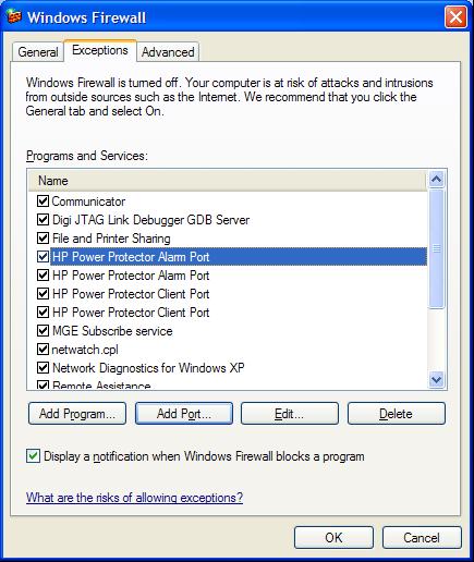
67 Firewall configuration 67
Dell Network Management Card. User's Guide. w w w. d e l l. c o m s u p p o r t. d e l l. c o m
 Dell Network Management Card User's Guide w w w. d e l l. c o m s u p p o r t. d e l l. c o m Notes and Warnings NOTE: A NOTE indicates important information that helps you make better use of your software.
HPE Intelligent Power Distribution Unit User Guide
 HPE Intelligent Power Distribution Unit User Guide Abstract This document includes installation, configuration, and operation information for the HPE Intelligent Power Distribution Unit. This document
HP Intelligent Modular Power Distribution Unit User Guide
 HP Intelligent Modular Power Distribution Unit User Guide Part Number 572153-001 March 2010 (First Edition) Copyright 2010 Hewlett-Packard Development Company, L.P. The information contained herein is
HPE Intelligent Power Distribution Unit Installation Instructions
 HPE Intelligent Power Distribution Unit Installation Instructions Important safety information For important safety, environmental, and regulatory information, see Safety and Compliance Information for
Network Management Card (66102 & 66103)
") www.mgeops.com Network Management Card (66102 & 66103) User manual Network Management Card User Manual 34003991EN/DA Page 1/120 Contents 1 MGE OFFICE PROTECTION SYSTEMS NETWORK SOLUTION 5 1.1 GENERAL PRESENTATION
www.mgeops.com Network Management Card (66102 & 66103) User manual Network Management Card User Manual 34003991EN/DA Page 1/120 Contents 1 MGE OFFICE PROTECTION SYSTEMS NETWORK SOLUTION 5 1.1 GENERAL PRESENTATION
QuickSpecs. HPE UPS Network Module. Overview. Models HPE UPS Network Module Mini-slot Kit
 Overview The new allows an HPE Uninterruptible Power System (UPS) to be directly connected to the network for remote monitoring and management of either a single UPS, or two UPSs in a redundant configuration.
STS Web card for Upsilon/Epsilon STS (66073) STS Web card User Manual
 STS Web card User Manual") STS Web card User Manual STS Web card for Upsilon/Epsilon STS (66073) STS Web card User Manual 34003765EN/BB Contents 1 PRESENTATION...3 1.1 OVERVIEW...3 1.2 USE IN A UPS...3 1.3 FUNCTIONS...4 1.4 TECHNICAL
STS Web card User Manual STS Web card for Upsilon/Epsilon STS (66073) STS Web card User Manual 34003765EN/BB Contents 1 PRESENTATION...3 1.1 OVERVIEW...3 1.2 USE IN A UPS...3 1.3 FUNCTIONS...4 1.4 TECHNICAL
SNMP Web Management. User s Manual
 SNMP Web Management User s Manual Suitable Product: SNMP Web Card SNMP Web Box Management Software for Uninterruptible Power Supply Systems Table of Contents 1. Overview... 1 1.1 Introduction... 1 1.2
HP Intelligent Management Center Branch Intelligent Management System (BIMS) User Guide
 User Guide") HP Intelligent Management Center Branch Intelligent Management System (BIMS) User Guide Abstract This guide contains basic information for network administrators, engineers, and operators who use the Branch
HP Intelligent Management Center Branch Intelligent Management System (BIMS) User Guide Abstract This guide contains basic information for network administrators, engineers, and operators who use the Branch
HP ProLiant Agentless Management Pack (v 3.2) for Microsoft System Center User Guide
 for Microsoft System Center User Guide") HP ProLiant Agentless Management Pack (v 3.2) for Microsoft System Center User Guide Abstract This guide provides information on using the HP ProLiant Agentless Management Pack for System Center version
HP ProLiant Agentless Management Pack (v 3.2) for Microsoft System Center User Guide Abstract This guide provides information on using the HP ProLiant Agentless Management Pack for System Center version
HP Management Integration Framework 1.7
 HP Management Integration Framework 1.7 Administrator Guide Abstract This document describes the use of HP Management Integration Framework interfaces and is intended for administrators involved in the
User s Manual PowerPanel Shutdown Service Graceful Shutdown and Notification service to ensure power protection of your computer
 User s Manual PowerPanel Shutdown Service Graceful Shutdown and Notification service to ensure power protection of your computer K01-SNMP004-00 TABLE OF CONTENTS INTRODUCTION... 1 INSTALLATION GUIDE...
HPE ilo Federation User Guide for ilo 5
 HPE ilo Federation User Guide for ilo 5 Abstract This guide explains how to configure and use the HPE ilo Federation features. It is intended for system administrators, Hewlett Packard Enterprise representatives,
Network Management Card. User Manual
 User Manual 1 Contents Contents 2 Chapter 1 Overview 3 1.1 NMC package contents 4 1.2 NMC CD Resources 4 1.3 Features 4 1.4 NMC Applications 5 Chapter 2 NMC parameters setting via serial COM port 6 2.1
KYOCERA Net Admin User Guide
 KYOCERA Net Admin User Guide Legal Notes Unauthorized reproduction of all or part of this guide is prohibited. The information in this guide is subject to change without notice. We cannot be held liable
Industrial Serial Device Server
 1. Quick Start Guide This quick start guide describes how to install and use the Industrial Serial Device Server. Capable of operating at temperature extremes of -10 C to +60 C, this is the Serial Device
IPMI Configuration Guide
 IPMI Configuration Guide 1. Introduction of IPMI Server Manager... 2 2. IPMI Server Manager GUI Overview... 3 1 1. Introduction of IPMI Server Manager IPMI Server Manager allows remote access of computers
HP integrated Citrix XenServer Online Help
 HP integrated Citrix XenServer Online Help Part Number 486855-002 September 2008 (Second Edition) Copyright 2008 Hewlett-Packard Development Company, L.P. The information contained herein is subject to
Dominion KSX II. Quick Setup Guide. Package Contents. Item. Amount included. Resolutions
 Dominion KSX II Quick Setup Guide Thank you for your purchase of the KSX II, the industry's most full-featured, enterprise-class, secure, digital KVM (Keyboard, Video, Mouse) and serial console switch.
USER MANUAL. PowerFrame TM Personal. UPS Monitoring Software
 USER MANUAL PowerFrame TM Personal UPS Monitoring Software www.bxterra.com 1 TABLE OF CONTENTS Introduction... Structure... Applications... Features... System Requirements... Supported Operating Systems...
Network Management Card. User Manual
 User Manual 1 Contents Contents 2 Chapter 1 Overview 3 1.1 NMC package contents 4 1.2 NMC CD Resources 4 1.3 Features 4 1.4 NMC Applications 5 Chapter 2 NMC parameters setting via serial COM port 6 2.1
User s Manual PowerPanel Shutdown Service Graceful Shutdown and Notification service to ensure power protection of your computer
 User s Manual PowerPanel Shutdown Service Graceful Shutdown and Notification service to ensure power protection of your computer Version 1.3 TABLE OF CONTENTS INTRODUCTION... 1 INSTALLATION GUIDE... 4
HP Intelligent Management Center v7.1 Branch Intelligent Management System Administrator Guide
 HP Intelligent Management Center v7.1 Branch Intelligent Management System Administrator Guide Abstract This document describes how to administer the HP IMC Branch Intelligent Management System. HP Part
HP P4000 SAN Solution User Guide
 HP P4000 SAN Solution User Guide Abstract This guide provides information for configuring and using the HP SAN Solution. It includes hardware configuration and information about designing and implementing
Dominion KX II-101. Quick Setup Guide. Step 1: Configure the Target Server
 Dominion KX II-101 Quick Setup Guide Thank you for your purchase of the KX II-101, the industry's most full-featured, enterprise-class, secure, digital KVM (Keyboard, Video, Mouse) switch. This Quick Setup
HP LeftHand SAN Solutions
 HP LeftHand SAN Solutions Support Document Installation Manuals VSA 8.0 Quick Start - Demo Version Legal Notices Warranty The only warranties for HP products and services are set forth in the express warranty
Dominion KX II-101-V2
 Dominion KX II-101-V2 Quick Setup Guide Thank you for your purchase of the KX II-101-V2, the industry's most full-featured, enterprise-class, secure, digital KVM (Keyboard, Video, Mouse) switch. This Quick
HP BladeSystem Management Pack (v 1.x) for Microsoft System Center User Guide
 for Microsoft System Center User Guide") HP BladeSystem Management Pack (v 1.x) for Microsoft System Center User Guide Abstract This guide provides information on using the HP BladeSystem Management Pack for System Center version 1.x to manage
HP BladeSystem Management Pack (v 1.x) for Microsoft System Center User Guide Abstract This guide provides information on using the HP BladeSystem Management Pack for System Center version 1.x to manage
HP BladeSystem c-class Virtual Connect Support Utility Version Release Notes
 HP BladeSystem c-class Virtual Connect Support Utility Version 1.9.1 Release Notes Abstract This document provides release information for the HP BladeSystem c-class Virtual Connect Support Utility Version
HPE StoreEver MSL6480 Tape Library Version 5.50 Firmware Release Notes
 HPE StoreEver MSL6480 Tape Library Version 5.50 Firmware Release Notes Abstract This document provides information about enhancements and fixes to the firmware for the HPE StoreEver MSL6480 Tape Library.
QuickSpecs HP Power Manager 4.2
 Overview HP Power Manager is a web-based application that enables administrators to manage an HP UPS from a browser-based management console. Administrators can monitor, manage, and control a single UPS
HPE Intelligent Management Center
 HPE Intelligent Management Center Service Health Manager Administrator Guide Abstract This guide provides introductory, configuration, and usage information for Service Health Manager (SHM). It is for
ViewPower. User s Manual. Management Software for Uninterruptible Power Supply Systems
 ViewPower User s Manual Management Software for Uninterruptible Power Supply Systems Table of Contents 1. ViewPower Overview...2 1.1. Introduction...2 1.2. Structure...2 1.3. Applications...2 1.4. Features...3
The Cosy 131 User Guide USER MANUAL
 The Cosy 131 User Guide USER MANUAL UM-0004-00 EN 1.1 ENGLISH Important User Information Liability Every care has been taken in the preparation of this document. Please inform HMS Industrial Networks SA
AOS-W 6.4. Quick Start Guide. Install the Switch. Initial Setup Using the WebUI Setup Wizard
 AOS-W 6.4 Quick Start Guide This document describes the initial setup of an Alcatel-Lucent user-centric network that consists of an Alcatel-Lucent switch and Alcatel-Lucent Access Points (APs). The installation
Online Help StruxureWare Data Center Expert
 Online Help StruxureWare Data Center Expert Version 7.2.7 What's New in StruxureWare Data Center Expert 7.2.x Learn more about the new features available in the StruxureWare Data Center Expert 7.2.x release.
HPE Security ArcSight Connectors
 HPE Security ArcSight Connectors SmartConnector for Microsoft DHCP File Configuration Guide October 17, 2017 Configuration Guide SmartConnector for Microsoft DHCP File October 17, 2017 Copyright 2006 2017
AppPulse Active. User Guide March 2016
 AppPulse Active User Guide March 2016 Legal Notices Warranty The only warranties for Hewlett Packard Enterprise products and services are set forth in the express warranty statements accompanying such
HPE Intelligent Management Center
 HPE Intelligent Management Center EAD Security Policy Administrator Guide Abstract This guide contains comprehensive information for network administrators, engineers, and operators working with the TAM
For details on using the LX, access online help from the application, or download help in PDF format from the Support page on Raritan's website.
 Dominion LX Quick Setup Guide Thank you for your purchase of the Dominion LX. The LX is the industry's highest quality, most affordable digital KVM (Keyboard, Video, Mouse) switch for your growing SMB
HP Accelerated iscsi for Multifunction Network Adapters User Guide
 HP Accelerated iscsi for Multifunction Network Adapters User Guide Part Number 410538-00J December 2007 (Ninth Edition) Copyright 2006, 2007 Hewlett-Packard Development Company, L.P. The information contained
User Manual WatchPower
 User Manual WatchPower Management Software for SP Efecto / SP Brilliant (Plus) / SP Initial Table of Contents 1. WatchPower Overview...1 1.1. Introduction... 1 1.2. Features... 1 2. WatchPower Install
Epson Device Admin User s Guide NPD EN
 Epson Device Admin User s Guide NPD5817-00 EN About this Manual About this Manual Marks and Symbols! Caution: Instructions that must be followed carefully to avoid bodily injury. c Important: Instructions
HPE BladeSystem c-class Virtual Connect Support Utility Version Release Notes
 HPE BladeSystem c-class Virtual Connect Support Utility Version 1.12.0 Release Notes Abstract This document provides release information for the HPE BladeSystem c-class Virtual Connect Support Utility
Viewing System Status, page 404. Backing Up and Restoring a Configuration, page 416. Managing Certificates for Authentication, page 418
 This chapter describes how to maintain the configuration and firmware, reboot or reset the security appliance, manage the security license and digital certificates, and configure other features to help
Innovative Electronics for a Changing World INDEX
 Innovative Electronics for a Changing World INDEX 1. SYSTEM DESCRIPTION 2. BOARD CONNECTIONS terminals and indicators 3. CONNECTION DIAGRAM 4. START UP GUIDE and passwords 5. HOME PAGE 6. STATUS PAGE 7.
User s Manual. Management Software for Uninterruptible Power Supply Systems
 ViewPowerMini User s Manual Management Software for Uninterruptible Power Supply Systems Table of Contents 1. ViewPowerMini Overview...2 1.1. Introduction...2 1.2. Structure...3 1.3. Features...3 2. ViewPowerMini
HP Load Balancing Module
 HP Load Balancing Module System Management Configuration Guide Part number: 5998-4216 Software version: Feature 3221 Document version: 6PW100-20130326 Legal and notice information Copyright 2013 Hewlett-Packard
Table Of Contents. 1. Introduction... 1
 User Manual Table of Content Table Of Contents 1. Introduction... 1 1.1 Brief Introduction to Web Interfaces... 1 1.2 How to Log In... 1 1.3 General Setting... 2 1.3.1 Date and Time Setting... 2 1.3.2
SNMP IPv6 for UPS. Save This Manual
 SNMP IPv6 for UPS Save This Manual This manual contains important instructions and warnings that you should follow during the installation, operation, storage and maintenance of this product. Failure to
Chapter 3 Managing System Settings
 Chapter 3 Managing System Settings Using the System Settings Utility The navigation pane at the top of the web browser interface contains a System tab that enables you to manage your FS700TSSmart Switch
UCON-IP-NEO Operation Web Interface
 UCON-IP-NEO Operation Web Interface copyright G&D 25/01/2012 Web Interface version 2.30 Subject to possible errors and technical modifications License notes G&D license Copyright G&D GmbH 2003-2012: All
ViewPower. User s Manual. Management Software for Uninterruptible Power Supply Systems
 ViewPower User s Manual Management Software for Uninterruptible Power Supply Systems Table of Contents 1. ViewPower Overview... 2 1.1. Introduction... 2 1.2. Structure... 2 1.3. Applications... 3 1.4.
airhaul Nexus sb3010
 u n w i r i n g o u r w o r l d TM airhaul Nexus sb3010 User Configuration Guide Version 1.3 Copyright smartbridges Pte Ltd. All Rights Reserved. About This Document This Software Configuration Guide is
HPE VMware ESXi and vsphere 5.x, 6.x and Updates Getting Started Guide
 HPE VMware ESXi and vsphere 5.x, 6.x and Updates Getting Started Guide Abstract This guide is intended to provide setup information for HPE VMware ESXi and vsphere. Part Number: 818330-003 Published: April
HPE ProLiant Gen9 Troubleshooting Guide
 HPE ProLiant Gen9 Troubleshooting Guide Volume II: Error Messages Abstract This guide provides a list of error messages associated with HPE ProLiant servers, Integrated Lights-Out, Smart Array storage,
Management and Printing User Guide
 Management and Printing User Guide Copyright 2007 Hewlett-Packard Development Company, L.P. Windows is a U. S. registered trademark of Microsoft Corporation. Intel and Centrino are trademarks or registered
Wireless Network Video Recorder
 LD2R/LD2R500 Wireless Network Video Recorder User Guide Version 1.0 PREFACE Thank you for purchasing the Wireless Network Video Recorder, an IP based device that installed on your network, which can be
Intelligent Provisioning 3.10 Release Notes
 Intelligent Provisioning 3.10 Release Notes Part Number: 881705-002 Published: February 2018 Edition: 1 Copyright 2017, 2018 Hewlett Packard Enterprise Development LP Notices The information contained
HP AutoPass License Server
 HP AutoPass License Server Software Version: 9.0 Windows, Linux and CentOS operating systems Support Matrix Document Release Date: October 2015 Software Release Date: October 2015 Page 2 of 10 Legal Notices
24-Port Gigabit with 4 Optional 10G Slots. Layer 3 Managed Stackable Switch XGS Quick Installation Guide
 24-Port Gigabit with 4 Optional 10G Slots Layer 3 Managed Stackable Switch XGS3-24040 Quick Installation Guide Table of Contents 1. Package Content... 3 2. Switch Management... 4 3. Requirements... 5 4.
VIEVU DOCKING STATION USER GUIDE
 VIEVU DOCKING STATION USER GUIDE Contact Us If you need assistance or have any questions, please visit www.vievu.com/docking-station-support, contact us by phone at 888-285-4548 or email support@vievu.com.
Minislot Transverse Environment Sensor 66846
 Minislot 66244 Transverse 66074 Environment Sensor 66846 Management Card 34003676EN/GA Page 1/69 Table of Contents 1 MGE NETWORK SOLUTION 4 1.1 INTRODUCTION 4 1.1.1 Connecting the UPS to the 4 The Management
Dominion KSX II. Quick Setup Guide. Step 1: Configure the KVM Target Servers
 Dominion KSX II Quick Setup Guide Thank you for your purchase of the KSX II, the industry's most full-featured, enterprise-class, secure, digital KVM (Keyboard, Video, Mouse) and serial console switch.
Intelligent Provisioning 3.00 Release Notes
 Intelligent Provisioning 3.00 Release Notes Part Number: 881705-001b Published: October 2017 Edition: 3 Copyright 2017 Hewlett Packard Enterprise Development LP Notices The information contained herein
User Manual PDUTracker
 User Manual PDUTracker Management Software for PDU Table of Contents 1. Overview... 1 1.1. Introduction... 1 1.2. Features... 1 2. Install and Uninstall... 1 2.1. System Requirement... 1 2.2. Software
Installing the Cisco Unified Videoconferencing 3545 MCU
 CHAPTER 2 Installing the Cisco Unified Videoconferencing 3545 MCU The Cisco Unified Videoconferencing 3545 MCU works together with a Cisco Unified Videoconferencing 3545 EMP Enhanced Media Processor (EMP)
TABLE OF CONTENTS COPYRIGHT INTRODUCTION...3 PRODUCT OVERVIEW...3 COMPONENTS AND FEATURES...3 HARDWARE INSTALLATION
 TABLE OF CONTENTS COPYRIGHT...2 1. INTRODUCTION...3 PRODUCT OVERVIEW...3 COMPONENTS AND FEATURES...3 HARDWARE INSTALLATION...3 2. MFP SERVER INSTALLATION...5 PREPARATION...5 CONFIGURATION SOLUTION TABLE...5
Hewlett Packard Enterprise StoreOnce 3100, 3500 and 5100 System Installation and Configuration Guide
 Hewlett Packard Enterprise StoreOnce 3100, 3500 and 5100 System Installation and Configuration Guide Abstract This guide is for HPE StoreOnce System Administrators. It assumes that the user has followed
HPE OfficeConnect 1620 Switch Series
 HPE OfficeConnect 1620 Switch Series User Guide Part number: 5998-5672R Software version: Release 1110 Document version:6w102-20160330 Copyright 2016 Hewlett Packard Enterprise Development LP The information
Configuring Cisco TelePresence Manager
 CHAPTER 3 Revised: November 27, 2006, First Published: November 27, 2006 Contents Introduction, page 3-1 System Configuration Tasks, page 3-2 Security Settings, page 3-3 Database, page 3-4 Room Phone UI,
Configuring and Managing the IP Camera
 CHAPTER 3 The Cisco Video Surveillance IP Camera provides configuration windows that you use to configure and manage the IP camera. This chapter explains how to access the configuration windows, describes
HPE Security ArcSight Connectors
 HPE Security ArcSight Connectors SmartConnector for HPE H3C Syslog Configuration Guide October 17, 2017 Configuration Guide SmartConnector for HPE H3C Syslog October 17, 2017 Copyright 2012 2017 Hewlett
LevelOne FBR User s Manual. 1W, 4L 10/100 Mbps ADSL Router. Ver
 LevelOne FBR-1416 1W, 4L 10/100 Mbps ADSL Router User s Manual Ver 1.00-0510 Table of Contents CHAPTER 1 INTRODUCTION... 1 FBR-1416 Features... 1 Package Contents... 3 Physical Details... 3 CHAPTER 2
Thank you for your purchase of the KX II, the industry's most full-featured, enterprise-class, secure, digital KVM (Keyboard, Video, Mouse) switch.
 switch.") Dominion KX II Quick Setup Guide Thank you for your purchase of the KX II, the industry's most full-featured, enterprise-class, secure, digital KVM (Keyboard, Video, Mouse) switch. This Quick Setup Guide
Dominion KX II Quick Setup Guide Thank you for your purchase of the KX II, the industry's most full-featured, enterprise-class, secure, digital KVM (Keyboard, Video, Mouse) switch. This Quick Setup Guide
HP Insight Remote Support Advanced HP StorageWorks P4000 Storage System
 HP Insight Remote Support Advanced HP StorageWorks P4000 Storage System Migration Guide HP Part Number: 5900-1089 Published: August 2010, Edition 1 Copyright 2010 Hewlett-Packard Development Company, L.P.
HP StoreVirtual Storage Multi-Site Configuration Guide
 HP StoreVirtual Storage Multi-Site Configuration Guide Abstract This guide contains detailed instructions for designing and implementing the Multi-Site SAN features of the LeftHand OS. The Multi-Site SAN
HPE Intelligent Management Center
 HPE Intelligent Management Center Branch Intelligent Management System Administrator Guide Abstract This document describes how to administer the HPE IMC Branch Intelligent Management System. Part number:
Enclosure rear components
 HP BladeSystem Insight Display components Item Description Function 1 Insight Display screen Displays Main Menu error messages and instructions 2 Left arrow button Moves the menu or navigation bar selection
Configuring and Managing the IP Camera
 CHAPTER 3 The Cisco Video Surveillance IP Camera provides configuration windows that you use to configure and manage the IP camera. This chapter explains how to access the configuration windows, describes
Power Xpert Meter 2000 Gateway Card Kit
 Quick Start Guide IL02601011E PXM 2250 PXM 2260 IQ 250 IQ 260 Power Xpert Meter 2000 Gateway Card Kit Table of Contents Remove the Meter From Service.... 2 Disconnect Power Connections, CTs, and Modbus....
ETHM-2. Ethernet Module. SATEL sp. z o.o. ul. Schuberta Gdańsk POLAND tel
 Ethernet Module ETHM-2 Firmware version 1.0 ethm2_en 09/08 SATEL sp. z o.o. ul. Schuberta 79 80-172 Gdańsk POLAND tel. + 48 58 320 94 00 info@satel.pl www.satel.pl SATEL's goal is to continually improve
ACE Live on RSP: Installation Instructions
 ACE Live on RSP ACE Live on RSP: Installation Instructions These installation instructions apply to OPNET ACE Live on RSP Release 7.1.3. You can find the latest version of this document at the OPNET Support
User Manual. AC ac Wireless Access Point/Router. Model WAC124. NETGEAR, Inc.
 AC2000 802.11ac Wireless Access Point/Router Model WAC124 December 2018 202-11885-02 NETGEAR, Inc. 350 E. Plumeria Drive San Jose, CA 95134, USA AC2000 802.11ac Support Thank you for purchasing this NETGEAR
HP JetAdvantage Security Manager. User Guide
 HP JetAdvantage Security Manager User Guide Copyright 2017 HP Development Company, L.P. Reproduction, adaptation, or translation without prior written permission is prohibited, except as allowed under
HP Intelligent Management Center Remote Site Management User Guide
 HP Intelligent Management Center Remote Site Management User Guide Abstract This book provides overview and procedural information for Remote Site Management, an add-on service module to the Intelligent
HPE Security ArcSight Connectors
 HPE Security ArcSight Connectors SmartConnector for Barracuda Firewall NG F- Series Syslog Configuration Guide October 17, 2017 Configuration Guide SmartConnector for Barracuda Firewall NG F-Series Syslog
Installation Procedure Red Hat 7 with Netscape 6
 Installation Procedure Red Hat 7 with Netscape 6 Pre-installation Requirements Before proceeding with the installation of a WatchGuard SOHO unit, you must have the following: A computer with a 10BaseT
HPE 3PAR OS MU3 Patch 18 Upgrade Instructions
 HPE 3PAR OS 3.1.3 MU3 Patch 18 Upgrade Instructions This upgrade instructions document is for installing Patch 18 on the HPE 3PAR Operating System Software 3.1.3.334 (MU3). This document is for Hewlett
Network USB over IP Server With 1-USB2.0 Port. User Manual V1.0
 Network USB over IP Server With 1-USB2.0 Port User Manual V1.0 1 2 TABLE OF CONTENTS COPYRIGHT...4 1. INTRODUCTION...5 PRODUCT OVERVIEW...5 COMPONENTS AND FEATURES...5 HARDWARE INSTALLATION...5 2. THE
HP LeftHand P4000 Virtual SAN Appliance in an HP BladeSystem environment solution guide
 HP LeftHand P4000 Virtual SAN Appliance in an HP BladeSystem environment solution guide AT459-96002 Part number: AT459-96002 First edition: April 2009 Legal and notice information Copyright 2009 Hewlett-Packard
HPE Security ArcSight Connectors
 HPE Security ArcSight Connectors SmartConnector for IP Flow (NetFlow/J-Flow) Configuration Guide October 17, 2017 SmartConnector for IP Flow (NetFlow/J-Flow) October 17, 2017 Copyright 2004 2017 Hewlett
Configuring and Managing the IP Camera
 CHAPTER 3 The Cisco Video Surveillance IP Camera provides configuration windows that you use to configure and manage the IP camera. This chapter explains how to access the configuration windows, describes
vcenter Server Appliance Configuration Update 1 Modified on 04 OCT 2017 VMware vsphere 6.5 VMware ESXi 6.5 vcenter Server 6.5
 Update 1 Modified on 04 OCT 2017 VMware vsphere 6.5 VMware ESXi 6.5 vcenter Server 6.5 You can find the most up-to-date technical documentation on the VMware Web site at: https://docs.vmware.com/ The VMware
TFC-1600MM Media Conversion System. Management Configuring Guide
 TFC-1600MM Media Conversion System Management Configuring Guide CONFIGURING THE SYSTEM This chapter provides network managers and system administrators with information about how to configure the Media
SIMATIC NET. Industrial Ethernet Security SCALANCE S615 Getting Started. Preface. Connecting SCALANCE S615 to the WAN 1
 Preface Connecting SCALANCE S615 to the WAN 1 SIMATIC NET VPN tunnel between SCALANCE S615 and 2 SINEMA RC Server Industrial Ethernet Security Getting Started 07/2017 C79000-G8976-C390-02 Legal information
IBM FlashSystem 720 & FlashSystem 820 Remote Support Overview
 IBM FlashSystem 720 & FlashSystem 820 Remote Support Overview Copyright IBM Corporation 2014 i Applicable Products Product: IBM FlashSystem 720 Product Version(s): 6.3.1-p10, 6.3.0 Product: IBM FlashSystem
Management Software for Uninterruptible Power Supply Systems
 Management Software for Uninterruptible Power Supply Systems Table of Contents 1. Forza Overview...2 1.1. Introduction...2 1.2. Structure...2 1.3. Applications...3 1.4. Features...3 2. Forza Install and
Dolphin ebase. Communication Cradle for the Dolphin 9700 Mobile Computer. User s Guide
 Dolphin ebase Communication Cradle for the Dolphin 9700 Mobile Computer User s Guide Introduction The Ethernet Base (ebase) enables a single Dolphin 9700 computer to communicate with a host device over
Installing and Managing the Switch
 CHAPTER 2 This chapter describes how to install and manage the Cisco SFS 7008 system hardware and contains these sections: Safety, page 2-2 Preparing the Site, page 2-3 Rack-Mounting the Switch, page 2-4