Network Camera Web3.0 Operation Manual. Version 3.5.2
|
|
|
- Osborn Lindsey
- 6 years ago
- Views:
Transcription
1 Network Camera Web3.0 Operation Manual Version 3.5.2
2 Table of Contents 1 Network Connection Main Interface Introduction Log in Live Interface Encode Setup System Menu Video Window Option Video Window Setup PTZ Control Setup Camera Conditions Video Audio Network TCP/IP Connection PPPoE DDNS IP filter SMTP ( ) UPnP SNMP Bonjour Multicast...32 i
3 WIFI Qos Event Video detect Alarm Abnormity Storage Record schedule and snapshot schedule Destination Record control System General Account PTZ Default Import/Export Auto maintenance Upgrade Information Version Log Online User Alarm Log out...59 Important The following functions are for reference only. Some series products may not support all the functions listed below. ii
4 1 Network Connection These series network camera products support the Web access and management via PC. Web includes several modules includes monitor channel preview, PTZ control, system configuration, alarm and etc. Please follow the steps listed below for network connection. Make sure the network camera has connected to the network properly. Network camera IP address and PC IP address shall be in the same network segment. If there is router, please set the corresponding gateway and subnet mask. Use order ping ***.***.***.***(* network camera address) to check connection is OK or not. 1
5 2 Main Interface Introduction 2.1 Log in Open IE and input network camera address in the address bar. For example, if your camera IP is , then please input in IE address bar. See Figure 2-1. Input your IP address here Figure 2-1 IE The login interface is shown as below. See Figure 2-2. Please input your user name and password. Default factory name is admin and password is admin. Note: For security reasons, please modify your password after you first login. 2


6 Figure 2-2 Login Interface If it is your first time to login in, system pops up warning information to ask you whether install control webrec.cab or not. Please click OK button, system can automatically install the control. When system is upgrading, it can overwrite the previous Web too. If you can t download the ActiveX file, please check whether you have installed the plug-in to disable the control download. Or you can lower the IE security level. See Figure 2-3. Figure 2-3 Security Settings 3

7 2.2 Live Interface After you logged in, you can see the live monitor window. See Figure 2-4 Figure 2-4 Live Interface There are four sections: Section 1: Encode setup bar Section 2: System menu Section 3: Window function option bar Section 4: Window adjust bar 2.3 Encode Setup The encode setup interface is shown as in Figure 2-5. Figure 2-5 Encode setup Please refer to the following sheet for detailed information. Parameter Main stream In normal network width environment, main stream can record audio/video file and realize network monitor. You can set the main stream resolution if your device supports. 4
8 Sub (Extra) stream Protocol If network width is not sufficient, you can use sub stream to realize network monitor. You can select stream media protocol from the dropdown list. There are three options: TCP/UDP/Multicast 2.4 System Menu System menu is shown as in Figure 2-6. Please refer to chapter 2.2 Live, chapter 3 PTZ, chapter 4 Setup, chapter 5 Alarm, chapter 6 Log out for detailed information. Figure 2-6 System Menu 2.5 Video Window Option The interface is shown as below. See Figure Figure 2-7 Video Window Please refer to the following sheet for detailed information. SN Parameter 1 Alarm output 2 Digital zoom Click it to generate an alarm output. You can see the icon becomes red. Click it again; you can disable the alarm output. When the video is in the original status, click it you can select any zone to zoom in. In the non-original status, you can drag the zoom-in zone in specified range. Right click mouse to restore previous status. Click it; you can use the middle button of the mouse to zoom in/out the video size. 3 Snapshot You can snapshoot important video. All images are memorized in system folder: \ picture download (default). You can go to Setup->Camera->Video->Path to modify the local record save path. 4 Triple snap Click it, system can snap at 1f/s. All images are memorized in system storage folder. 5
9 5 Record When you click local record button, the system begins recording. The recorded file is saved to system folder: \ RecordDownload(default). You can go to Setup->Camera->Video->Path to modify the local record save path. 6 Easy focus Click it, you can see there are two parameters on the preview video:af Peak and AF Max. AF Peak: It is to display the video definition during the focus process. AF Max: It is the most suitable value for the video definition. The close the AF Peak and AF Max is, the better the focus effect is. 7 Audio output Turn on or off audio when you are monitoring. 8 Bidirectional talk Click it to begin audio talk. You can go to Setup->Camera- >Audio to set bidirectional talk mode. 9 Help Click it to open help file. 2.6 Video Window Setup The interface is shown as in Figure Figure 2-8 Video Window Setup Please refer to the following sheet for detailed information. SN Parameter 1 Image control 2 Original size Click it to open picture setup interface. See Figure 2-9. This interface is on the top right pane. Click this button to go to original size. It is to display the actual size of the video stream. It depends on the resolution of the bit stream. 3 Full screen Click it to go to full-screen mode. Double click the mouse or click the Esc button to exit the full screen. 4 Width and height ratio Click it to restore original ratio or suitable window. The picture setup interface is shown as in Figure

10 Figure 2-9 Please refer to the following sheet for detailed information. Parameter Video setup It is to adjust monitor video brightness. It is to adjust monitor video contrast ness. It is to adjust monitor video saturation. It is to adjust monitor video hue. Note: All the operations here apply to WEB end only. Please go to Setup- >Camera->Conditions to adjust corresponding items. Reset Restore brightness, contrastness saturation and hue to system default setup. 7
.")

11 3 PTZ Control Please note only IPC-HFxxxx series product support PTZ function. Before PTZ operation, please make sure you have properly set PTZ protocol. (Please go to Setup- >System->PTZ to set.). Here you can view direction keys, speed, zoom, focus, iris, preset, tour, pan, scan, pattern, aux close, and PTZ setup button. See Figure 3-1. PTZ direction: PTZ supports eight directions: left/right/up/down/upper left/upper right/bottom left/bottom right. Speed: The step 8 speed is faster than step 1. Figure 3-1 PTZ Interface PTZ setting interface is shown as in Figure 3-2. Here you can set scan, preset, tour, pattern, assistant function and light and wiper. 8

12 Figure 3-2 PTZ Setup Please refer to the following sheet for PTZ setup information. Parameter Scan Click Setup button, you can set scan left and right limit. Move the camera to you desired location and then click left limit button. Then move the camera again and then click right limit button to set a right limit. Preset Input the preset value and then click Preset button, the camera turns to the corresponding position of the preset. Click the Set preset button, you can set a preset. Use direction keys to move the camera to your desired location and then input preset value. Click add button, you have set one preset. The preset value ranges from 1 to 255. (It may vary due to different protocols.) Tour Click the Setup button, you can begin set tour. Input tour value and then click the Set button. The tour value ranges from 1 to 255. (It may vary due to different protocols.) Input preset value in the column. Click Add preset button, you have added one preset in the tour. Note: Repeat the above procedures you can add more presets in one tour. Or you can click delete preset button to remove one preset from the tour. Pattern You can input pattern value and then click start button to begin PTZ movement. Please go back to Figure 3-1 to implement camera operation. Then you can click stop button in Figure 3-2. Now you have set one pattern. 9
13 Parameter Assistant Light and wiper Please input the corresponding aux value here. You can select one option and then click AUX on or AUX off button. You can turn on or turn off the light/wiper. 10

14 4 Setup 4.1 Camera Conditions Here you can view device property information. Slight differences may be found due to different network camera series. The setups become valid immediately after you set. See Figure 4-1. Figure 4-1 Please refer to the following sheet for detailed information. Parameter Brightness It is to adjust monitor window bright. The value ranges from 0 to 100. The default value is 50. The larger the number, the bright the video is. When you input the value here, the bright section and the dark section of the video will be adjusted accordingly. You can use this function when the whole video is too dark or too bright. Please note the video may become hazy if the value is too high. The recommended value ranges from 40 to
15 Contrast It is to adjust monitor window contrast. The value ranges from 0 to 100. The default value is 50. The larger the number, the higher the contrast is. You can use this function when the whole video bright is OK but the contrast is not proper. Please note the video may become hazy if the value is too low. If this value is too high, the dark section may lack brightness while the bright section may over exposure.the recommended value ranges from 40 to 60. Saturation Sharpness It is to adjust monitor window saturation. The value ranges from 0 to 100. The default value is 50. The larger the number, the strong the color is. This value has no effect on the general brightness of the whole video. The video color may become too strong if the value is too high. For the grey part of the video, the distortion may occur if the white balance is not accurate. Please note the video may not be attractive if the value is too low. The recommended value ranges from 40 to 60. The value here is to adjust the edge of the video. The larger the value is, the clear the edge is and vice versa. Please note there is noise if the value here is too high. The default value is 50 and the recommended value ranges from 40 to 60. Anti-flicker Outdoor: In this mode, you can switch exposure mode to get the effect under the corresponding exposure mode. 50Hz: When the current is 50Hz, system can auto adjust the exposure according to the environment brightness in case there is any strip. 60Hz: When the current is 60Hz, system can auto adjust the exposure according to the environment brightness in case there is any strip. Exposure Mode Auto mode The video whole brightness can automatically change within the proper exposure range according to the different environments. The higher the gain max value is, the lower the noise is. 12
16 Low noise The video whole brightness can automatically change within the proper exposure range according to the different environments. The higher the gain max value is, the lower the noise is. For the same environments, the noise of the low noise mode shall be smaller than the noise of the auto mode. Low motion blur The video whole brightness can automatically change within the proper exposure range according to the different environments. The lower the exposure max value is, the week the tail is. For the same environments, the noise of the low motion blur mode shall be smaller than that of the auto mode. Manual It is to display manual exposure value. Gain Adjust Exposure Mode The gain adjust is to set the gain value. The default value may vary due to different device models. The smaller the value, the low the noise. But the brightness is also too low in the dark environments. It can enhance the video brightness if the value is high. But the video noise may become too clear. There are two modes: Auto exposure (AE) and Manual exposure (ME). There are several values for the manual exposure mode. You can select from the dropdown list, It support the long exposure. It supports customized setup too. The device can auto exposure according to the exposure time you set here. The value ranges from 0.1 to 80ms. The exposure time is fixed if the max and min value are the same. Customized value: System can auto exposure according to the value you set here. The value ranges from 0.1 to 80ms. 13
17 Auto Iris Scene Mode Day&Night Before the setup, please make sure you have installed the auto iris. You can check the box before ON to enable this function. The auto iris may change if the light becomes different. When you disable this function, the iris is at the max. System does not add the auto iris function in the exposure control. This function is on by default. It is to set the white balance mode. It has effect on the general hue of the video. This function is on by default. You can select the different scene mode such as auto, sunny, cloudy, home, office, night, disable and etc to adjust the video to the best quality. Disabled: The white balance function is off. The video will be output at the original color. Auto: The auto white balance is on. System can auto compensate the color temperature to make sure the vide color is proper. Sunny: The threshold of the white balance is in the sunny mode. Night: The threshold of the white balance is in the night mode. Customized: You can set the gain of the red/blue channel. The value reneges from 0 to 100. It is to set device color and the B/W mode switch. The default setup is on. Color: Device outputs the color video. Auto: Device auto select to output the color or the B/W video according to the device feature (The general bright of the video or there is IR light or not.) B/W: The device outputs the black and white video. Switch by periods: You can se the day/night mode switch time. For example, you can set the sunrise time as 06:00:00 and the sunset time as 18:00:00. The video in the specified period will be color while the video in the rest period will be black and white. Backlight Mode BLC The device auto exposures according to the environments situation so that the darkest area of the video is cleared 14
18 Full-screen test WDR DWDR (Digital WDR) HLC Off button on the video window, you can begin full- Click the screen test. For the WDR scene, this function can lower the high bright section and enhance the brightness of the low bright section. So that you can view these two sections clearly at the same time. The value ranges from 1 to 100. When you switch the camera from no-wdr mode to the WDR mode, system may lose several seconds record video. For the WDR scene, this function can lower the high bright section and enhance the brightness of the low bright section. So that you can view these two sections clearly at the same time. After you enabled HLC function, the device can lower the brightness of the brightest section according to the HLC control level. It can reduce the area of the halo and lower the brightness of the whole video. It is to disable the BLC function. Please note this function is disabled by default. Flip Mirror Cancel It is to switch video up and bottom limit. This function is disabled by default. The video resolution shall be 720P or below if you want to flip 90. It is to switch video left and right limit. This function is disabled by default. It is to cancel the operation in current interface. Default It is to set device default setup. Important The setup becomes immediately after you set. IPC-3110 series product does not support the low noise mode, low motion blur, defend flicker mode, digital WDR, HLC, flip, mirror and etc functions. You can see WDR option only if your camera supports WDR function. System does not support digital WDR, long-time exposure or low noise mode. 15

19 4.1.2 Video Video bit stream The video bit stream interface is shown as below. See Figure 4-2. Figure 4-2 Please refer to the following sheet for detailed information. Parameter Main stream Bit stream type It includes general stream, motion stream and alarm stream. You can select different encode frame rates form different recorded events. System supports active control frame function (ACF). It allows you to record in different frame rates. For example, you can use high frame rate to record important events, record scheduled event in lower frame rate and it allows you to set different frame rates for motion detection record and alarm record. 16
20 Parameter Encode mode Resolution Frame Rate Bit Rate Type There are three options: H.264(main profile standard, H.264B(baseline standard)encode and MJPG encode. H.264 :Main Profile encode mode. H.264B :Baseline Profile encode mode MJPEG :In this encode mode, the video needs larger bit stream to guarantee the video definition. You can use the max bit stream value in the recommend bit to get the better video output effect. There are multiple resolutions. You can select from the dropdown list. For each resolution, the recommended bit stream value is different. Important You can not set a resolution higher than 720P (not including 720P) when the flip function is in process. PAL: 1~25f/s,NTSC: 1~30f/s.. The frame rate may vary due to different resolutions. There are two options: VBR and CBR. Please note, you can set video quality in VBR mode. Sub stream Reference Bit Stream Reference bit rate value according to the resolution and frame rate you have set. Bit Rate In VBR, the bit rate here is the max value. In CBR, it is a fixed value. See reference bit stream for recommended value. I Frame Watermark Enable Bit stream type Here you can set the P frame amount between two I frames. The value ranges from 1 to 150. Default value is 50. Recommended value is frame rate *2. This function allows you to verify the video is tampered or not. Here you can select watermark bit stream, watermark mode and watermark character. Default character is DigitalCCTV. The max length is 85-digit. The character can only include number, character and underline. Please check the box here to enable extra stream function. This function is enabled by default. General bit stream. 17
21 Parameter Encode mode Resolution Frame Rate Bit Rate Type Recommended Bit Bit Rate I Frame There are three options: H.264(main profile standard, H.264B(baseline standard)encode and MJPG encode. The H.264 and H.264B both are H264 bit stream. H.264 is the Main Profile encode and the H.264B is the Baseline Profile encode mode. H.264B is for Blackberry cell phone to realize the monitor. You need to enable the sub stream function in your camera and set the resolution as CIF. Then you can monitor via the Blackberry cell phone. MJPEG: In this encode mode, the video needs to large bit stream to guarantee the video definition. You can use the max bit stream value in the recommend bit to get the better video output effect. There are multiple resolutions. You can select from the dropdown list. For each resolution, the recommended bit stream value is different. PAL: 1~25f/s,NTSC: 1~30f/s.. The frame rate may vary due to different resolutions. There are two options: VBR and CBR. Please note, you can set video quality in VBR mode. Recommended bit rate value according to the resolution and frame rate you have set. In CBR, the bit rate here is the max value. In dynamic video, system needs to low frame rate or video quality to guarantee the value. The value is null in VBR mode. Please refer to recommend bit rate for the detailed information. Here you can set the P frame amount between two I frames. The value ranges from 1 to 150. Default value is 50. Recommended value is frame rate * Snapshot The snapshot interface is shown as in Figure

22 Figure 4-3 Please refer to the following sheet for detailed information. Parameter Snapshot type Image size Quality There are two modes: general (schedule) and Event (activation). It is the same with the resolution of the main stream. It is to set the image quality. There are six levels. Interval It is to set snapshot frequency. The value ranges from 1s to 7s Video Overlay The video overlay interface is shown as in Figure 4-4. Figure 4-4 Please refer to the following sheet for detailed information. 19
23 Parameter Privacy mask Time Title Channel Title Here you can privacy mask the specified video in the monitor video. System max supports 4 privacy mask zones. You can enable this function so that system overlays time information in video window. You can use the mouse to drag the time tile position. You can enable this function so that system overlays channel information in video window. You can use the mouse to drag the channel tile position Path The storage path interface is shown as in Figure 4-5. Here you can set snap image saved path ( in the preview interface) and the record storage path ( in the preview interface).the default setup is C:\PictureDownload. Please click the Save button to save current setup. Figure Audio Please note IPC-HDB3xxxC series product does not support audio function. The audio interface is shown as below. See Figure
24 Figure 4-6 Please refer to the following sheet for detailed information. Parameter Audio enable Encode mode Main stream: Recorded file only contains video by default. You need to check the audio box here to enable audio function. Sub (Extra) stream: Recorded file only contains video by default. You need to check the audio box here to enable audio function. The encode mode of the main stream and extra stream include PCM, G.711A and G.711Mu. The setup here is for audio encode mode and the bidirectional talk encode both. 4.2 Network TCP/IP The TCP/IP interface is shown as in Figure
25 Figure 4-7 Please refer to the following sheet for detailed information. Parameter Host Name Ethernet Card Mode Mac Address It is to set current host device name. It max supports 32-digit character. Please select the Ethernet port. It is for the wire LAN by default. Please note for the -W series product, it has the wireless network card, and you can modify the default Ethernet port setup. Please note the device needs to reboot to activate the new setup once you modify the default setup. There are two modes: static mode and the DHCP mode. The IP/submask/gateway are null when you select the DHCP mode to auto search the IP. If you select the static mode, you need to set the IP/submask/gateway manually. If you select the DHCP mode, you can view the IP/submask/gateway from the DHCP. If you switch from the DHCP mode to the static mode, you need to reset the IP parameters. Besides, IP/submask/gateway and DHCP are read-only when the PPPoE dial is OK. It is to display hose Mac address. 22
26 IP Version IP Address Preferred DNS Alternate DNS Enable ARP/Ping set device IP address service. It is to select IP version. IPV4 or IPV6. You can access the IP address of these two version. Please use the keyboard to input the corresponding number to modify the IP address and then set the corresponding subnet mask and the default gateway. DNS IP address. Alternate DNS IP address. You can use ARP/Ping command to modify or set the device IP address if you know the device MAC address. Before the operation, please make sure the network camera and the PC in the same LAN. This function is on by default. You can refer to the steps listed below. Step 1: Get an IP address. Set the network camera and the PC in the same LAN. Step 2: Get the physical address from the label of the network camera. Step 3: Go to the Run interface and then input the following commands. arp s <IP Address> <MAC> ping l 480 t <IP Address> Such as:arp s c ping l 480 t Step 4: Reboot the device. Step 5: You can see the setup is OK if you can see there are output information such as Reply from from the command output lines. Now you can close the command line. Step 6: Open the browse and then input addres>. Click the Enter button, you can access now Connection The connection interface is shown as in Figure
27 Figure 4-8 Please refer to the following sheet for detailed information. Parameter Max connection TCP port UDP port HTTP port RTSP port It is the max Web connection for the same device. The value ranges from 1 to 20. The max connection amount is 20. The default value is You can input the actual port number if necessary. The default value is You can input the actual port number if necessary. The default value is 80. You can input the actual port number if necessary. The default value is 554. Rtsp stream query format is: Main stream: rtsp://username:password@ip:port/cam/realmonitor?channel=1&subtype=0 Sub stream: rtsp://username:password@ip:port/cam/realmonitor?channel=1&subtype=1 You need to input the following four items manually. Username/password/IP and port. The IP is device IP and the port default value is 554. You can leave it in blank if it is the default value. You do not need to input the user name and password if you do not need to the verification. Such as: rtsp://ip:port/cam/realmonitor?channel=1&subtype=0 24
28 HTTPs Enable Usually the default value is PPPoE The PPPoE interface is shown as in Figure 4-9. Input the PPPoE user name and password you get from the IPS (internet service provider) and enable PPPoE function. Please save current setup and then reboot the device to get the setup activated. Device connects to the internet via PPPoE after reboot. You can get the IP address in the WAN from the IP address column. Please note, you need to go to the IP address item to via the device current device information. You can access the client-end via this address. Figure DDNS The DDNS interface is shown as in Figure The DDNS is to set to connect the various servers so that you can access the system via the server. Please go to the corresponding service website to apply a domain name and then access the system via the domain. It works even your IP address has changed. 25

29 Figure 4-10 Please refer to the following sheet for detailed information. Parameter Server Type Server IP Server Port Domain Name User Password Update period You can select DDNS protocol from the dropdown list and then enable DDNS function. The private DDNS protocol means you use your self-defined private protocol to realize DDNS function. DDNS server IP address DDNS server port. Your self-defined domain name. The user name you input to log in the server. The password you input to log in the server. Device sends out alive signal to the server regularly. You can set interval value between the device and DDNS server here IP filter The IP filter interface is shown as in Figure You can enable IP filter function so that some specified IP user can access the network camera. You can add IP address or IP address section. If you do not check the box here, it means there is on access limit. 26
 The SMTP interface is")

30 Figure SMTP ( ) The SMTP interface is shown as in Figure Figure 4-12 Please refer to the following sheet for detailed information. 27
31 Parameter SMTP Server Port Anonymity User Name Password Sender Authentication (Encryption mode) Title (Subject) Attachment Mail receiver Interval Health mail enable Update period (interval) test Input server address and then enable this function. Default value is 25. You can modify it if necessary. For the server supports the anonymity function. You can auto login anonymously. You do not need to input the user name, password and the sender information. The user name of the sender account. The password of sender account. Sender address. You can select SSL or none. Input subject here. System can send out the of the snapshot picture once you check the box here. Input receiver address here. Max three addresses. The send interval ranges from 0 to 3600 seconds. 0 means there is no interval. Please note system will not send out the immediately when the alarm occurs. When the alarm, motion detection or the abnormity event activates the , system sends out the according to the interval you specified here. This function is very useful when there are too many s activated by the abnormity events, which may result in heavy load for the server. Please check the box here to enable this function. This function allows the system to send out the test to check the connection is OK or not. Please check the box to enable this function and then set the corresponding interval. System can send out the regularly as you set here. The system will automatically sent out a once to test the connection is OK or not.before the test, please save the setup information UPnP It allows you to establish the mapping relationship between the LAN and the public network. Here you can also add, modify or remove UPnP item. See Figure

32 In the Windows OS, From Start->Control Panel->Add or remove programs. Click the Add/Remove Windows Components and then select the Network Services from the Windows Components Wizard. Click the Details button and then check the Internet Gateway Device Discovery and Control client and UPnP User Interface. Please click OK to begin installation. Enable UPnP from the Web. If your UPnP is enabled in the Windows OS, the network camera can auto detect it via the My Network Places Figure SNMP The SNMP interface is shown as in Figure The SNMP allows the communication between the network management work station software and the proxy of the managed device. Please install the software such as MG MibBrowser 8.0c software or establish the SNMP service before you use this function. You need to reboot the device to activate the new setup. 29
33 Figure 4-14 Please refer to the following sheet for detailed information. Parameter SNMP Port Read Community Write Community Trap address The listening port of the proxy program of the device. It is a UDP port not a TCP port. The value ranges from 1 to The default value is 161 It is a string. It is a command between the manage process and the proxy process. It defined the authentication, access control and the management relationship between one proxy and one group of the managers. Please make sure the device and the proxy are the same. The read community will read all the objects the SNMP supported in the specified name. The default setup is public. It is a string. It is a command between the manage process and the proxy process. It defined the authentication, access control and the management relationship between one proxy and one group of the managers. Please make sure the device and the proxy are the same. The read community will read/write/access all the objects the SNMP supported in the specified name. The default setup is write. The destination address of the Trap information from the proxy program of the device. 30
34 Parameter Trap port The destination port of the Trap information from the proxy program of the device. It is for the gateway device and the client-end PC in the LAN to exchange the information. It is a non-protocol connection port. It has no effect on the network applications. It is a UDP port not TCP port. The value ranges from 1 to The default value is 162. SNMP version Check SNMP V1, system only processes the information of V1. Check SNMP V2, system only processes the information of V2. Check SNMP V3.you can set user name and password. There is account security verification when the server wants to connect to the device. At the same time, the v1 and V2 is null and can not select Bonjour The Bonjour interface is shown as below. See Figure Bonjour is based on the multicast DNS service from the Apple. The Bonjour device can automatically broadcast its service information and listen to the service information from other device. You can use the browse of the Bonjour service in the same LAN to search the network camera device and then access if you do not know the network camera information such as IP address. You can view the server name when the network camera is detected by the Bonjour. Please note the safari browse support this function. Click the Display All Bookmarks: and open the Bonjour, system can auto detect the network camera of the Bonjour function in the LAN. Figure

35 Multicast The multicast interface is shown as in Figure Multicast is a transmission mode of data packet. When there is multiple-host to receive the same data packet, multiple-cast is the best option to reduce the broad width and the CPU load. The source host can just send out one data to transit. This function also depends on the relationship of the group member and group of the outer. Here you can set multicast address and port. You also need to go to Live interface to set the protocol as Multicast. Figure WIFI Please note this function is for the device of WIFI module. The WIFI interface is shown as in Figure


36 Figure 4-17 Please check the box to enable WIFI function and then click the Search SSID button. Now you can view all the wireless network information in the following list. Double click a name to connect to it. See Figure Figure Qos The QoS interface is shown as below. See Figure
37 Qos (Quality of Service) is network security mechanism. It is a technology to fix the network delay and jam problem and etc. For the network service, the quality of service includes the transmission bandwidth, delay, the packet loss and etc. We can guarantee the transmission bandwidth, lower the delay, reduce the loss of the data packet and anti-dither to enhance the quality. We can set the DSCP (Differentiated Services Code Point) of the IP to distinguish the data packet so that the router or the hub can provide different services for various data packets. It can select the different queues according to the priority of the packets and select the bandwidth of the each queue. It can also discard at the different ratio when the broad bandwidth is jam. Figure 4-19 Please refer to the following sheet for detailed information. Parameter Real-time monitor Command The value ranges from 0 to 63. The router or the switcher can provide different service for various data packets. The value ranges from 0 to 63. The router or the switcher can provide different service for various data packets. 4.3 Event Video detect Motion Detect The motion detect interface is shown as in Figure

38 Figure 4-20 Figure
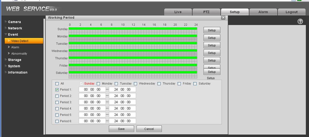
39 Figure 4-22 Please refer to the following sheet for detailed information. Parameter Enable Sensitivity Region Working Period Anti-dither You need to check the box to enable motion detection function. There are six levels. The sixth level has the highest sensitivity. There are six levels. The sixth level has the highest sensitivity. Region: If you select motion detection type, you can click this button to set motion detection zone. The interface is shown as in Figure There are PAL 22X18/NTSC 22X15 zones. Right click mouse you can go to full-screen display mode. Do remember clicking OK button to save your motion detection zone setup. Motion detection function becomes activated in the specified periods. See Figure There are six periods in one day. Please draw a circle to enable corresponding period. Select date. If you do not select, current setup applies to today only. You can select all week column to apply to the whole week. Click OK button, system goes back to motion detection interface, please click save button to exit. System only memorizes one event during the anti-dither period. The value ranges from 0s to 100s. 36

40 Parameter Relay out Alarm Delay Record channel Record Delay Send PTZ Snapshot Enable alarm activation function. You need to select alarm output port so that system can activate corresponding alarm device when alarm occurs. System can delay the alarm output for specified time after alarm ended. The value ranges from 10s to 300s. System auto activates motion detection channel to record once alarm occurs (working with motion detection function). Please note you need to go to Storage-> Schedule to set current channel as general record. System can delay the record for specified time after alarm ended. The value ranges from 10s to 300s. If you enabled this function, System can send out to alert you when alarm occurs and ends. Here you can set PTZ movement when alarm occurs. Such as go to preset x when there is an alarm. The event type includes: preset, tour and pattern. You need to check the box here so that system can backup motion detection snapshot file Video Masking The video masking interface is shown as in Figure Figure

41 Figure 4-24 Please refer to the following sheet for detailed information. Parameter Enable Sensitivity Area Working Period Anti-dither You need to check the box to enable this function. There are six levels. The sixth level has the highest sensitivity. There are six levels. The sixth level has the highest sensitivity. Region: you can click this button to set Video masking zone. The interface is shown as in Figure There are PAL 22X18/NTSC 22X15 zones. Right click mouse you can go to full-screen display mode. Do remember clicking OK button to save your Video masking zone setup. Video masking function becomes activated in the specified periods. There are six periods in one day. Please draw a circle to enable corresponding period. Select date. If you do not select, current setup applies to today only. You can select all week column to apply to the whole week. Click OK button, system goes back to motion detection interface, please click save button to exit. System only memorizes one event during the anti-dither period. The value ranges from 0s to 100s. 38
42 Parameter Relay out Alarm Delay Record channel Record Delay PTZ Capture Enable alarm activation function. You need to select alarm output port so that system can activate corresponding alarm device when alarm occurs. System can delay the alarm output for specified time after alarm ended. The value ranges from 10s to 300s. System auto activates motion detection channel to record once alarm occurs (working with motion detection function). Please note you need to go to Storage-> Schedule to set current channel as general record. System can delay the record for specified time after alarm ended. The value ranges from 10s to 300s. If you enabled this function, System can send out to alert you when alarm occurs. Here you can set PTZ movement when alarm occurs. Such as go to preset x when there is an alarm. The event type includes: preset, tour and pattern. You need to input capture channel number so that system can backup motion detection snapshot file Alarm Please note IPC-HDB3xxxC series product does not support this function Alarm activation The alarm activation interface is shown as in Figure Figure
43 Please refer to the following sheet for detailed information. Parameter Enable Working Period Anti-dither Sensor type Relay out Alarm Delay Record Channel Record Delay Send PTZ Snapshot You need to check the box to enable this function. This function becomes activated in the specified periods. There are six periods in one day. Please draw a circle to enable corresponding period. Select date. If you do not select, current setup applies to today only. You can select all week column to apply to the whole week. Click OK button, system goes back to motion detection interface; please click save button to exit. System only memorizes one event during the anti-dither period. The value ranges from 0s to 100s. There are two options: NO/NC. There is 1-channel alarm output. Corresponding to motion detection alarm output port. Enable alarm activation function. You need to select alarm output port so that system can activate corresponding alarm device when alarm occurs. System can delay the alarm output for specified time after alarm ended. The value ranges from 10s to 300s. System auto activates motion detection channel to record once alarm occurs (working with motion detection function). Please note you need to go to Storage-> Schedule to set current channel as general record. System can delay the record for specified time after alarm ended. The value ranges from 10s to 300s. If you enabled this function, System can send out to alert you when alarm occurs and ends. Here you can set PTZ movement when alarm occurs. Such as go to preset x when there is an alarm. The event type includes: preset, tour and pattern. You need to input capture channel number so that system can backup motion detection snapshot file Relay output The relay output interface is shown as in Figure
44 Figure 4-26 Please refer to the following sheet for detailed information. Parameter Alarm output Refresh There is only one output channel. Please click the button 1. If you want to enable the alarm activation output function, please press the corresponding button and then trigger. Search alarm output status Abnormity It includes five statuses: No SD card, capacity warning, SD card error, and disconnection and IP conflict. There are two interfaces for you reference. See Figure 4-27 through Figure Figure
45 Figure 4-28 Figure 4-29 Figure
46 Figure 4-31 Please refer to the following sheet for detailed information. Parameter Event Type Record Record Delay Relay Out Relay out Delay Send The abnormal events include: no disk, no space, disk error, net error, offline, IP conflict. Threshold: You can set the minimum percentage value here. The device can alarm when capacity is not sufficient. You need to draw a circle to enable this function. System auto activates channel to record once alarm occurs (For offline type only. See Figure ). You need to check the box to enable this function. System can delay the record for specified time after alarm ended. The value ranges from 10s to 300s. The corresponding alarm output channel when alarm occurs. You need to check the box to enable this function. The alarm output can delay for the specified time after alarm stops. The value ranges from 10s to 300s. If you enable this function, system can send out to alarm the specified user. This function is invalid when network is offline or IP conflict occurs. 4.4 Storage Record schedule and snapshot schedule In these two interfaces, you can add or remove the schedule record/snapshot setup. See Figure There are three record modes: general (auto), motion detect and alarm. There are six periods in one day. Please make sure you have enabled the corresponding record mode in the Setup->Storage- >Conditions. 43

in the Schedule interface.")
47 You can view the current time period setup from the color bar. Green color stands for the general record/snapshot. Yellow color stands for the motion detect record/snapshot.. Red color stands for the alarm record/snapshot. Figure Destination The destination interface is shown as in Figure It is to set the storage mode of the network camera record file or snapshot pictures. There are two options: local/ftp. You can only select one mode. System can save according to the event types. It is corresponding to the three modes (general/motion/alarm)in the Schedule interface. Please check the box to enable the save functions. Figure 4-33 Please refer to the following sheet for detailed information. 44


48 Parameter Event Type Local FTP It includes: general, motion detect and alarm. It saved in the SD card. It saved in the FTP server. The local interface is shown as in Figure Here you can view local SD card or disk information. You can also operate the read-only, write-only, hot swap and format operation. Figure 4-34 The FTP interface is shown as in Figure You need to check the box to enable the FTP function. When network disconnect occurred or there is malfunction. Emergency storage can save the record/snapshot picture to the local SD card Record control Figure
49 The record control interface is shown as in Figure Figure 4-36 Please refer to the following sheet for detailed information. Parameter Pack Duration Here you can select file size. Default setup is 8 minutes. Pre-record Disk Full Record mode Record stream Please input pre-record value here. For example, system can record the four seconds video in the buffer. The record begins from the fifth second. There are two options: stop recording or overwrite the previous files when HDD is full. Stop: Current working HDD is overwriting or current HDD is full, it will stop record. Overwrite: Current working HDD is full; it will overwrite the previous file. There are three modes: Auto/manual/close. There are two options: main stream and sub stream. 4.5 System General The general interface includes the local host setup and the date/time setup Local host The local host interface is shown as in Figure

50 Figure 4-37 Please refer to the following sheet for detailed information. Parameter Device No Video Standard It is to set device name. This is to display video standard such as PAL. Language You can select the language from the dropdown list. Please note the device needs to reboot to get the modification activated Date and time The date and time interface is shown as in Figure Figure
51 Please refer to the following sheet for detailed information. Parameter Date format Time Format Time zone System time Sync PC DST NTP NTP server Here you can select date format from the dropdown list. There are two options: 24-H and 12-H. The time zone of the device. It is to set system time. It becomes valid after you set. You can click this button to save the system time as your PC current time. Here you can set day night save time begin time and end time. You can set according to the date format or according to the week format. You can check the box to enable NTP function. You can set the time server address. Port Update period It is to set the time server port. It is to set the sync periods between the device and the time server Account Note: For the character in the following user name or the user group name, system max supports 6-digits. The space in the front or at the end of the string is null. The valid string includes: character, number, and underline. The user amount is 20 and the group amount is 8 when the device is shipped out of the factory. The factory default setup includes two levels: user and admin. You can set the corresponding group and then set the rights for the respective user in the specified groups. User management adopts group/user modes. The user name and the group name shall be unique. One user shall be included in only one group User name In this interface you can add/remove user and modify user name. See Figure
52 Figure 4-39 Add user: It is to add a name to group and set the user rights. See Figure There are four default users: admin/888888/ and hidden user default. Except user 6666, other users have administrator right. The user can only have the monitor rights,. Hidden user default is for system interior use only and can not be deleted. When there is no login user, hidden user default automatically login. You can set some rights such as monitor for this user so that you can view some channel view without login. Here you can input the user name and password and then select one group for current user. Please note the user rights shall not exceed the group right setup. For convenient setup, please make sure the general user has the lower rights setup than the admin. 49
53 Figure 4-40 Modify user It is to modify the user property, belonging group, password and rights. See Figure Modify password It is to modify the user password. You need to input the old password and then input the new password twice to confirm the new setup. Please click the OK button to save. Please note, the password ranges from 1-digit to 6-digit. It shall include the number only. For the user of the account rights, he can modify the password of other users. Figure
54 Group The group management interface can add/remove group, modify group password and etc. The interface is shown as in Figure Figure 4-42 Add group: It is to add group and set its corresponding rights. See Figure Please input the group name and then check the box to select the corresponding rights. It includes: shutdown/reboot device, live view, record control, PTZ control and etc. Figure 4-43 Modify group Click the modify group button, you can see an interface is shown as in Figure
55 Here you can modify group information such as remarks and rights. Figure PTZ Please note only IPC-HFxxxx series product support this function. The PTZ interface is shown as in Figure Figure 4-45 Please refer to the following sheet for detailed information. Parameter Protocol Address Select the corresponding dome protocol. Set corresponding dome address. Default value is 1. Please note your setup here shall comply with your dome address; otherwise you can not control the speed dome. 52

56 Parameter Baud Rate Data Bit Stop bit Parity Select the dome baud rate. Default setup is Default setup is 8. Please set according to the speed dome dial switch setup. Default setup is 1. Please set according to the speed dome dial switch setup. Default setup is none. Please set according to the speed dome dial switch setup Default The default setup interface is shown as in Figure Please note system can not restore some information such as network IP address Import/Export The interface is shown as in Figure Figure
57 Figure 4-47 Please refer to the following sheet for detailed information. Parameter Import Export It is to import the local setup files to the system. It is to export the corresponding system setup to your local PC Auto maintenance The auto maintenance interface is shown as in Figure Here you can select auto reboot and auto delete old files interval from the dropdown list. If you want to use the auto delete old files function, you need to set the file period. Figure Upgrade The upgrade interface is shown as in Figure

58 Please select the upgrade file and then click the update button to begin firmware update. Important Improper upgrade program may result in device malfunction! 4.6 Information Figure Version The version interface is shown as in Figure Here you can view system hardware features, software version, release date and etc. Please note the following information is for reference only. Figure Log Here you can view system log. See Figure
59 Figure 4-51 Please refer to the following sheet for log parameter information. Parameter Type Log types include: system operation, configuration operation, data operation, event operation, record operation, user management, log clear. Start time End time Search Detailed information Set the start time of the requested log. Set the end time of the requested log. You can select log type from the drop down list and then click search button to view the list. You can click the stop button to terminate current search operation. You can select one item to view the detailed information. Clear Backup You can click this button to delete all displayed log files. Please note system does not support clear by type. You can click this button to backup log files to current PC Online User The online user interface is shown as in Figure Here you can view current online user, group name, IP address and login time. 56
60 Figure

61 5 Alarm Please note IPC-HDB3xxxC series product does not support this function. Click alarm function, you can see an interface is shown as in Figure 5-1. Here you can set device alarm type and alarm sound setup. Figure 5-1 Alarm Please refer to the following sheet for detailed information. Type Parameter Alarm type Motion detection System alarms when motion detection alarm occurs, Disk full System alarms when disk is full. HDD malfunction System generates an alarm when HDD is malfunction. Camera masking System alarms when camera is viciously masking. External alarm Alarm input device sends out alarm. Operation Prompt System automatically pops up alarm dialogue box. Alarm audio Audio Path When alarm occurs, system auto generates alarm audio. The audio supports customized setup. Here you can specify alarm sound file. 58

62 6 Log out Click log out button, system goes back to log in interface. See Figure 6-1. Figure 6-1 Logout Note: This manual is for reference only. Slight difference may be found in user interface. All the designs and software here are subject to change without prior written notice. All trademarks and registered trademarks mentioned are the properties of their respective owners. If there is any uncertainty or controversy, please refer to the final explanation of us. Please visit our website for more information. 59
Speed Dome Web Operation Manual. Version 3.0.0
 Speed Dome Web Operation Manual Version 3.0.0 Table of Contents 1 Network Connection...1 2 Main Interface Introduction...2 2.1 Log in...2 2.2 Live Interface...4 2.3 Encode Setup...4 2.4 System Menu...5
XL-ICA-306M1 User's manual
 XL-ICA-306M1 User's manual Version 3.0.0 Table of Contents 1 Network Connection...1 2 Main Interface Introduction...2 2.1 Log in...2 2.2 Live Interface...4 2.3 Encode Setup...4 2.4 System Menu...5 2.5
IPVDPT-EL3MP Web Operation Manual. Version 4.0.2
 IPVDPT-EL3MP Web Operation Manual Version 4.0.2 Table of Contents 1 Network Connection... 1 2 Main Interface Introduction... 2 2.1 Log in... 2 2.2 Live Interface... 7 2.3 Encode Setup... 8 2.4 System Menu...
Network Camera Web3.0 Operation Manual
 Network Camera Web3.0 Operation Manual Version 4.0.2 Zhejiang Dahua Technology CO.,LTD Table of Contents 1 Network Connection... 1 2 Main Interface Introduction... 2 2.1 Log in... 2 2.2 Live Interface...
Network Camera Web3.0 Operation Manual
 Network Camera Web3.0 Operation Manual Version 1.0.0E i Table of Contents 1 Network Connection... 1 2 Main Interface Introduction... 2 2.1 Log in... 2 2.2 Live Interface... 6 2.3 Encode Setup... 6 2.4
B0. Illustra Essentials Network Camera Web3.0 User Manual
 8200-1102-07 B0 Illustra Essentials Network Camera Web3.0 User Manual Notice Please read this manual thoroughly and save it for future use before attempting to connect or operate this unit. The information
Speed Dome Web3.0 Operation Manual. Version 4.2.0
 Speed Dome Web3.0 Operation Manual Version 4.2.0 Table of Contents 1 Network Connection...1 1.1 Preparation...1 1.2 Log in...1 1.3 Live Interface...3 1.4 Encode Setup...3 1.5 Video Window Setup...4 1.6
Outdoor IPC Web Operation Manual Version1.0
 Outdoor IPC Web Operation Manual Version1.0 1 Table of Contents 1 Network Connection...4 2 Main Interface Introduction...5 2.1 Log in...5 2.2 Monitor Channel Menu Tree...8 2.3 System Menu...10 2.4 Monitor
Speed Dome Web3.0 Operation Manual. Version 4.3.0
 Speed Dome Web3.0 Operation Manual Version 4.3.0 Table of Contents 1 Network Connection...1 1.1 Preparation...1 1.2 Log in...1 1.3 Live Interface...3 1.4 Encode Setup...3 1.5 Video Window Setup...4 1.6
K6 Series IP Camera Web Operation Manual
 K6 Series IP Camera Web Operation Manual Version1.3 1 Table of Contents 1 Network Connection...4 2 Main Interface Introduction...5 2.1 Log in...5 2.2 Monitor Channel Menu Tree...7 2.3 System Menu...10
Speed Dome Web3.0 Operation Manual. Version 4.1.0
 Speed Dome Web3.0 Operation Manual Version 4.1.0 Table of Contents 1 Network Connection...1 1.1 Preparation...1 1.2 Log in...1 1.3 Live Interface...3 1.4 Encode Setup...3 1.5 Video Window Setup...4 1.6
Network Camera Web3.0 Operation Manual
 Network Camera Web3.0 Operation Manual Version 1.1.0F i Table of Contents 1 Network Config... 1 1.1 Network Connection... 1 1.2 Log in... 1 2 Live... 7 2.1 Encode Setup... 7 2.2 System Menu... 8 2.3 Video
Network Speed Dome Web3.0 Operation Manual
 Network Speed Dome Web3.0 Operation Manual Version 1.0.0 Table of Contents 1 Network Connection... 1 1.1 Preparation... 1 1.2 Log in... 1 1.3 Live Interface... 3 1.4 Encode Setup... 3 1.5 Video Window
E-Series Management Software User s Manual
 E-Series Management Software User s Manual Version 1.12.1 Table of Contents 1 OVERVIEW AND ENVIRONMENT... 1 1.1 Overview... 1 1.2 Performance... 1 1.3 Environments... 1 2 INSTALLATION AND UPGRADE... 2
Network Camera Operating Instructions
 Network Camera Operating Instructions Model No WV-V2530LK WV-V2530L1 WV-V1330LK WV-V1330L1 Version 1.0.2 Table of Contents 1. Network Connection 2 2. Main Interface Introduction 3 2.1 Log in 3 2.2 Live
Dahua IR Thermal Imaging Network Camera Web3.0
 Dahua IR Thermal Imaging Network Camera Web3.0 Operation Manual Version 1.0.0 i Table of Contents 1 Network Config... 1 1.1 Network Connection... 1 1.2 Log in... 1 2 Live... 6 2.1 Encode Setup... 6 2.2
1,3 Megapixel bullet camera with IR LED. User Manual
 391782 1,3 Megapixel bullet camera with IR LED LE05643AA-01CB-12W40 EN Indice 1 General Introduction...3 1.1 Accessories...3 1.2 Features...3 1.3 Specifications...4 1.3.1 Performance...4 1.3.2 Factory
E-37-FSW Dome Camera Operation Manual
 E-37-FSW Dome Camera Operation Manual i Table of Contents 1 Network Config... 1 1.1 Network Connection... 1 1.2 Log in... 1 2 Live... 6 2.1 Encode Setup... 6 2.2 System Menu... 7 2.3 Video Window Function
Network Camera Operation Manual K-EF235L01E
 Network Camera Operation Manual Model No. K-EW215L01E K-EF235L01E Version 1.0.0 Table of Contents 1 Network Connection... 1 2 Main Interface Introduction... 2 2.1 Log in... 2 2.2 Live Interface... 6 2.3
Montavue MNR800 Series NVR User Manual
 Montavue MNR800 Series NVR User Manual Table of Contents 1 Local Basic Operation...1 1.1 Boot up and Shutdown...1 1.1.1 Boot up...1 1.1.2 Shutdown...1 1.2 Change/Reset Password...1 1.2.1 Change Password...1
IP CAMERA User Manual 695h, 755h, 795h
 IP CAMERA User Manual 695h, 755h, 795h 1 Contents Chapter 1 - Login... 4 Chapter 2 - Main Interface... 6 2.1 Main Interface Display Status... 6 2.2 Operation of Live View Interface... 6 Chapter 3 - Setting
1,3 Megapixel IP dome camera USER MANUAL
 1,3 Megapixel IP dome camera 4 306 32 USER MANUAL LE05639AA Sommaire 1 General Introduction...3 1.1 Accessories...3 1.2 Features...3 1.3 Specifications...4 1.3.1 Performance...4 1.3.2 Factory Default Settings...5
1,3 Megapixel IP dome camera. User Manual
 391771 1,3 Megapixel IP dome camera LE05638AA-01CB-12W40 EN Indice 1 General Introduction...3 1.1 Accessories...3 1.2 Features...3 1.3 Specifications...4 1.3.1 Performance...4 1.3.2 Factory Default Settings...5
Installation and Operations Manual
 DLA-DNA Client Software Installation and Operations Manual Model Number: DLA and DNA Series Description: DVR and NVR Client Management Software Smart Professional Surveillance System User s Manual Version
Dahua IR Thermal Imaging Speed Dome Web3.0 Operation Manual
 Dahua IR Thermal Imaging Speed Dome Web3.0 Operation Manual Version 1.0.0 Dahua Technology CO., LTD i Table of Contents 1 Network Config... 1 1.1 Network Connection... 1 1.2 Log in... 1 2 Live... 6 2.1
Dahua Network Camera Web3.0 Operation Manual
 Dahua Network Camera Web3.0 Operation Manual Version 1.0.1 Dahua Vision Technology CO., LTD i Table of Contents 1 Network Config... 1 1.1 Network Connection... 1 1.2 Log in... 1 2 Live... 6 2.1 Encode
Amcrest Surveillance Pro User s Manual
 Amcrest Surveillance Pro User s Manual Version 1.0 Table of Contents 1 OVERVIEW AND ENVIRONMENT... 1 1.1 Overview... 1 1.2 Performance... 1 1.3 Environments... 1 2 INSTALLATION AND UPGRADE... 2 2.1 Installation...
Standalone DVR User s Manual. Figure 4-81
 Figure 4-81 4.11.2 Network 4.11.2.1 TCP/IP The single network adapter interface is shown as in Figure 4-82 and the dual network adapters interface is shown as in Figure 4-83 Network Mode : Includes multiple
Configuring and Managing the IP Camera
 CHAPTER 3 The Cisco Video Surveillance IP Camera provides configuration windows that you use to configure and manage the IP camera. This chapter explains how to access the configuration windows, describes
Instruction Manual FLIR IP Series. Firmware v2.210
 Instruction Manual FLIR IP Series Firmware v2.210 Table of contents 1 Overview...1 2 Web Configuration Setup...2 2.1 Supported Browsers...2 2.2 Internet Explorer Setup...2 2.3 Safari Setup...2 2.4 Firefox
HD IPCameras User's Mannual
 Thank you for purchasing our products, if you have any questions or need, please feel free to contact us. This manual applies to IPC-XXX series of network cameras. This manual may contain technical inaccuracies
Smart Professional Surveillance System User s Manual Version
 Smart Professional Surveillance System User s Manual Version 1.12.1 Instrukcja pobrana ze sklepu www.ekocentrum24.pl Table of Contents 1. OVERVIEW AND ENVIRONMENT... 1 1.1 Overview... 1 1.2 Performance...
VMS-A1 Client Software. User Manual
 VMS-A1 Client Software User Manual Contents Contents... 2 Chapter1. Overview... 4 1.1 Description... 4 1.2 Features & Functions... 4 Chapter2. Update Info... 6 Chapter3. Starting VMS-A1... 7 3.1 Installing
A0. Holis HD Remote Client User Manual
 8200-1368-03 A0 Holis HD Remote Client User Manual Notice Please read this manual thoroughly and save it for future use before attempting to connect or operate this unit. The information in this manual
Dahua Speed Dome Web3.0 Operation Manual
 Dahua Speed Dome Web3.0 Operation Manual Version 1.0.0 Zhejiang Dahua Vision Technology Co., LTD i Table of Contents 1 Network Config... 1 1.1 Network Connection... 1 1.2 Log in WEB Interface... 2 2 Common
EZ-IP Network Camera Web3.0 Operation Manual Version 1.0.0
 EZ-IP Network Camera Web3.0 Operation Manual Version 1.0.0 i Table of Contents 1 Product Overview... 1 2 Initial Config... 2 2.1 Device Initialization... 2 2.2 Login and Logout... 4 2.2.1 Log in WEB Interface...
CAMERAS IP START SERIES
 CAMERAS IP START SERIES Contents 1. Login Interface... 3 2. Preview... 4 2.1 Open/Close Preview... 5 2.2 Full-screen Preview... 5 2.3 Electronic Zoom-in... 5 2.3 PTZ Control... 6 3. File Management...
IndigoVision. BX and GX Range Cameras. Web Configuration Guide
 IndigoVision BX and GX Range Cameras Web Configuration Guide BX and GX Range - Cameras THIS MANUAL WAS CREATED ON 11/27/2017. DOCUMENT ID: IU-BX-MAN001-4 Legal considerations LAWS THAT CAN VARY FROM COUNTRY
XIPLED Software User s Manual. For Firmware release V3.5.0.*
 XIPLED1080-36 Software User s Manual For Firmware release V3.5.0.* Product name: XIPLED1080-36 Release Date: 2014/10/02 Manual Revision: V02 Feature XIPLED1080-36 Live View All Series Camera/Video/Audio
Configuring and Managing the IP Camera
 CHAPTER 3 The Cisco Video Surveillance IP Camera provides configuration windows that you use to configure and manage the IP camera. This chapter explains how to access the configuration windows, describes
Configuring and Managing the IP Camera
 CHAPTER 3 The Cisco Video Surveillance IP Camera provides configuration windows that you use to configure and manage the IP camera. This chapter explains how to access the configuration windows, describes
Instruction Manual FLIR Network Camera Series
 Instruction Manual FLIR Network Camera Series Instruction Manual FLIR Network Camera Series #LX400073; r.46243/46243; en-us iii Table of contents 1 Overview...1 2 Web Configuration Setup...2 2.1 Internet
Pro7804N1 NVR User Manual
 Pro7804N1 NVR User Manual Pro7804N1 User Manual BW R6.indd 1 User Information Admin User Name: Admin Password: IP Address: System Name: Table Of Contents 1. Menu Operation...4 1.1 Main Menu...4 2. Start
Pro71600N3 NVR User Manual
 Pro71600N3 NVR User Manual User Information Admin User Name: Admin Password: IP Address: System Name: Table Of Contents 1. Menu Operation...4 1.1 Main Menu...4 2. Start & Shutdown System...5 2.1 Start
Dahua HDCVI Series DVR User s Manual Version 1.2.0
 Dahua HDCVI Series DVR User s Manual Version 1.2.0 4 OVERVIEW OF NAVIGATION AND CONTROLS... 93 4.1 Boot up and Shutdown...93 4.1.1 Boot up...93 4.1.2 Shutdown...93 4.1.3 Auto Resume after Power Failure...93
NVMS1000. User Manual
 NVMS1000 User Manual Contents 1 Software Introduction... 1 1.1 Summary... 1 1.2 Operation Environment... 1 1.3 Install and Uninstall... 2 1.3.1 Install the Software... 2 1.3.2 Uninstall the Software...
PROVISION-ISR. User Manual. All S Series IP Cameras I1-390IPS36 DI-390IPS36 I1-330IPS36 DI-330IPS36. All rights reserved Provision-ISR
 (v4.0.2) PROVISION-ISR All S Series IP Cameras I1-390IPS36 DI-390IPS36 I1-330IPS36 DI-330IPS36 User Manual All rights reserved Provision-ISR Notes on Safety Please refer to the technical specs to choose
Contents. Introduction Overview Range of Application Product Description Operation Environment...
 Contents Introduction... 3 1. Overview... 4 1.1 Range of Application... 4 1.2 Product Description... 4 1.3 Operation Environment... 5 2. Device Connection... 5 3. Device Operation Instructions... 6 3.1
IndigoVision. BX and GX Range Cameras. Web Configuration Guide
 IndigoVision BX and GX Range Cameras Web Configuration Guide BX and GX Range - Cameras THIS MANUAL WAS CREATED ON 4/11/2018. DOCUMENT ID: IU-BX-MAN001-5 Legal considerations LAWS THAT CAN VARY FROM COUNTRY
Smart Professional Surveillance System User s Manual
 Smart Professional Surveillance System User s Manual Version 1.16.1 Table of Contents 1. OVERVIEW AND ENVIRONMENT...1 1.1 Overview...1 1.2 Performance...1 1.3 Environments...1 2. INSTALLATION AND UPGRADE...2
Network Cameras NVC-BM1 NVC-DF1 NVC-DT1 NVC-DM1. User Manual
 Network Cameras NVC-BM1 NVC-DF1 NVC-DT1 NVC-DM1 User Manual V1.0 0 For further information, including full user and installation manual, and technical support please visit: www.hills.com.au/videosecurity
NVMS1000. User Manual
 NVMS1000 User Manual Contents 1 Software Introduction... 1 1.1 Summary... 1 1.2 Operation Environment... 1 1.3 Install and Uninstall... 2 1.3.1 Install the Software... 2 1.3.2 Uninstall the Software...
QRT-502. IE Operation Manual
 QRT-502 IE Operation Manual Contents 1. Home.. 2 2. Replay.... 5 3. Media.... 6 3-1. Video.... 6 3-2. Audio.... 7 3-3. Image.... 8 3-4. OSD.... 9 3-5. PTZ (Not supported in QRT-501) 4. Parameters.... 10
NVMS-7000 Client Software User Manual Version 1.03
 NVMS-7000 Client Software User Manual Version 1.03 Contents Chapter 1. Overview... 3 1.1 Description... 3 1.2 Running Environment... 3 Chapter 2. Starting NVMS-7000... 4 2.1 User Registration... 4 2.2
IP Camera user manual
 IP Camera user manual Product name:high definition IP Camera Document version:4.2 Editions suit for 1080P IP Camera Precautions Search and Login...1 Device searching...2 Install plugin...3 A. Real-time
Network Speed Dome & PTZ Camera Web3.0 Operation Manual
 Network Speed Dome & PTZ Camera Web3.0 Operation Manual Version 1.0.0 i Table of Contents 1 Network Config... 1 1.1 Network Connection... 1 1.1 Log in WEB Interface... 2 1.1.1 Device Initialization...
NVMS User Manual
 NVMS-1000 User Manual Contents 1 Software Introduction...1 1.1 Summary... 1 1.2 Operation Environment... 1 1.3 Install and Uninstall... 2 1.3.1 Install the Software... 2 1.3.2 Uninstall the Software...
UltraConnect Wi-Fi IP Camera Configuration Manual
 UltraConnect Wi-Fi IP Camera Configuration Manual P/N 1073065-EN REV A ISS 16SEP15 Copyright Trademarks and patents Manufacturer Contact information 2015 United Technologies Corporation. Interlogix is
TENVIS Technology Co., Ltd. User Manual. For H.264 Cameras. Version 1.0.0
 TENVIS Technology Co., Ltd User Manual For H.264 Cameras Version 1.0.0 Catalogue Basic Operation... 3 Hardware Installation... 3 Search Camera... 3 For Internet Explorer... 6 Playback Record Files... 9
IPC Online Operation Manual
 IPC Online Operation Manual 1 Overview An IP camera (hereinafter referred to as IPC) is a new product integrating network video technologies into a traditional camera. The IPC can realize simpler monitoring
FISH-EYE IP CAMERAS EASY SERIES ART. IPFE071A-IPFE073A. Please read this manual thoroughly before use and keep it for future reference
 FISH-EYE IP CAMERAS EASY SERIES ART. IPFE071A-IPFE073A Please read this manual thoroughly before use and keep it for future reference 1 Network Connection This series of products support the access and
Enterprise Pro Surveillance System User s Manual
 Enterprise Pro Surveillance System User s Manual 1 Table of Contents 1 FEATURES... 6 2 INSTALLATION... 8 2.1 Environment...8 2.2 Installation...8 2.3 Un-installation...10 3 NAVIGATION AND CONTROLS OF THE
2.01 N : D1 resolution 37x Zoom Outdoor Network Vandal-proof PTZ Security Camera
 PART 1 - NOT USED PART 2 - PRODUCTS 2.01 N5013-37: D1 resolution 37x Zoom Outdoor Network Vandal-proof PTZ Security Camera A. Functional Description The specified product shall be an all-in-one style outdoor
IP WEB User Manual V2.0
 IP WEB User Manual V2.0 Please read carefully before installing or contacting your supplier. The information contained at the time of printing is correct, but is subject to change without notice. This
User s Manual of DVR ULTIMAX. Remote Client Software V wersja 2.40
 User s Manual of DVR ULTIMAX Remote Client Software V 4.0.1 ULTIMAX-304 ULTIMAX-308 ULTIMAX-316 ULTIMAX-504 ULTIMAX-508 ULTIMAX-516 ULTIMAX-704 ULTIMAX-708 ULTIMAX-716 wersja 2.40 Index 1 Software Install,
1. Introduction Overview Product Information... 3
 1. Introduction... 3 1.1 Overview... 3 1.2 Product Information... 3 2. Device Connection... 3 2.1 Connection Diagram... 3 2.2 Wi-Fi Setting... 4 2.2.1 Set up WiFi by Mobile Phone... 4 2.2.2 WPS/QSS One
WiFi NVR-Recorder PRO TX-64 User Manual
 WiFi NVR-Recorder PRO TX-64 User Manual V 1.0.0 Table of Contents 1 Features and Specifications...1 1.1 Overview...1 1.2 Features...1 1.3 Specifications...3 2 Front Panel and Rear Panel...5 2.1 Front Panel...5
F312A IP Camera. Firmware User Manual
 0 F312A User Manual F312A IP Camera F312A User Manual Firmware User Manual - Contents - CHAPTER 1. MINIMUM SYSTEM REQUIREMENT...2 CHAPTER 2. USING IP CAMERA VIA WEB BROWSER...3 2.1WINDOWS WEB BROWSER...3
Dahua Panoramic + PTZ Network Camera Web3.0 Operation Manual
 Dahua Panoramic + PTZ Network Camera Web3.0 Operation Manual Version 1.0.0 ZHEJIANG DAHUA VISION TECHNOLOGY CO., LTD. Table of Contents 1 Product Introduction... 1 1.1 Product Overview... 1 1.2 Function
F510E BOX IP Camera. Firmware User Manual
 0 F510E User Manual F510E BOX IP Camera F510E User Manual Firmware User Manual - Contents - CHAPTER 1. MINIMUM SYSTEM REQUIREMENT... 2 CHAPTER 2. USING IP CAMERA VIA WEB BROWSER... 3 CHAPTER 3. USING IP
M511E Pan/Tilt Day/Night IP Camera Firmware User Manual
 0 M511E User Manual M511E User Manual M511E Pan/Tilt Day/Night IP Camera Firmware User Manual - Contents - CHAPTER 1. MINIMUM SYSTEM REQUIREMENT... 2 CHAPTER 2. USING IP CAMERA VIA WEB BROWSER... 3 2.1WINDOWS
Pro7400H1 Hybrid DVR User Manual
 Pro7400H1 Hybrid DVR User Manual User Information Admin User Name: Admin Password: IP Address: System Name: Table Of Contents 1. Menu Operation... 4 1.1 Main Menu... 4 2. Start Up/Shutdown System... 5
Multi-spectral Thermal Camera Web3.0 Operation Manual
 Multi-spectral Thermal Camera Web3.0 Operation Manual Version 1.0.0 i Table of Contents 1 Network Config... 1 1.1 Network Connection... 1 1.2 WEB Interface Login... 1 2 Live... 4 2.1 Video Window Function
Software Manual EVI Standalone DVR User s Manual
 Software Manual EVI Standalone DVR User s Manual Default: Username: admin Password: 1234 140217 i Table of Contents 1 OVERVIEW OF NAVIGATION AND CONTROLS... 1 1.1 Boot up and Shutdown... 1 1.1.1 Boot up...
Installation Instructions Fig. 3 Side View. No. Label Operation
 One-Camera IP Video Server In G Out G D+ D- Installation Instructions 1507280 Part Number: CM2002 - One-Camera IP Video Server CM2002 IP Video Server Features In G Out G D+ D- DO G DI G Out In Video In
TruVision 11/31 Series IP Camera FW 5.1 Configuration Manual
 TruVision 11/31 Series IP Camera FW 5.1 Configuration Manual P/N 1072856D REV 1.0 ISS 04MAR15 Copyright Trademarks and patents Manufacturer Contact information 2015 United Technologies Corporation. Interlogix
USER MANUAL. Mac Version
 USER MANUAL Mac Version Contents 1 Software Introduction... 1 1.1 Summary... 1 1.2 Install and Uninstall... 1 1.2.1 Install the Software... 1 2 Login Software... 3 2.1 Login... 3 2.2 Control Panel Instruction...
NVMS User Manual
 NVMS-1000 User Manual Contents 1 Software Introduction...1 1.1 Summary... 1 1.2 Operation Environment... 1 1.3 Install and Uninstall... 2 1.3.1 Install the Software... 2 1.3.2 Uninstall the Software...
HLong Asia Industrial
 SDI DVR Stand alone digital video recorder HLong Asia Industrial Thank you for using the company's products! This manual describes only the host functions basic operation. Product design and specification
Network Camera OWNER S MANUAL *5PKA00129Q* Please read this manual carefully before operating your set and retain it for future reference.
 OWNER S MANUAL Network Camera Please read this manual carefully before operating your set and retain it for future reference. MODELS RNDF-BP0A RNDF-BP01A RNUF-BP01A *5PKA0019Q* 17077 (V1.0) Getting Started
LS VISION TECHNOLOGY CO.,LTD. Network Surveillance System Client Operating Instructions
 Network Surveillance System Client Operating Instructions 1 Directory 1. Overview... 4 2. Runtime Environment... 4 2.1 Machine Configuration Requirements...4 2.2 Operating System Requirements... 4 3. Software
Day & Night 6MP 360 Panorama Dome IR IP Camera
 Day & Night 6MP 360 Panorama Dome IR IP Camera Features Full HD 6.0 megapixel CMOS image sensor True H.264 AVC High Profile video compression H.264 and Motion JPEG multi-profile video streaming 3D noise
Day & Night 1080P HD Auto Focus Dome IP Camera
 Day & Night 1080P HD Auto Focus Dome IP Camera Features Full HD 2 megapixel CMOS image sensor True H.264 AVC/MPEG-4 part 10 real-time video compression H.264 and Motion JPEG multi-profile video streaming
TruVision Series 5 IP Camera Configuration Manual
 TruVision Series 5 IP Camera Configuration Manual P/N 1073340-EN REV A ISS 27JUN17 Copyright Trademarks and patents Manufacturer Certification 2017 United Technologies Corporation. Interlogix is part of
User Manual. For H.264 Cameras. Version 2.0.0
 User Manual For H.264 Cameras Version 2.0.0 Catalogue Basic Operation... 3 Camera Settings... 3 System... 3 Device Name... 4 Time... 4 User... 4 Network... 5 IP... 5 Port... 5 WiFi... 6 UPnP... 6 DDNS...
Introduction. IP Camera (including Storage IP Camera, WiFi/Storage IP Camera, IR Dome IP Camera, IR
 MANUAL Introduction Thank you for purchasing IP Cameras. A IP Camera (including Storage IP Camera, WiFi/Storage IP Camera, IR Dome IP Camera, IR Day and Night Waterproof IP Camera, and High Speed Dome
Day & Night Full HD Dome IR IP Camera
 Day & Night 1080P@60fps Full HD Dome IR IP Camera Features Full HD 2.0 Megapixel CMOS image sensor 1080P@60fps 3D noise reduction (MCTF) 2D WDR function HDR function up to 120dB Defog function Digital
IP Modular camera 1,3 MP USER MANUAL LE04761AB
 IP Modular camera 1,3 MP 4 306 60 USER MANUAL LE04761AB Indice 1 Accessories... 3 2 General Introduction... 4 2.1 Feature...4 2.2 Specifications...5 3 Framework... 7 3.1 Rear Panel...7 3.2 Side Panel...9
DH-SD6A220/230/S220-HNI
 2Mp Full HD 20x/30x Network IR PTZ Dome Camera Features Powerful 20x/30x optical zoom H.264 & MJPEG dual-stream encoding Max 60fps@720P and 30fps@1080P resolution Defog(220/230), DWDR(WDR), Day/Night(ICR),
SunEyes V Series IP Camera P2P CMS user manual
 SunEyes V Series IP Camera P2P CMS user manual Version: 2.0 Date: July. 2015 This document is applicable to all series devices in our company. Page 1 ON page 40 foreword The HiP2P client of IP Camera is
DS-2CD5046G0-(AP) 4 MP Smart Network Box Camera
 4 MP Smart Network Box Camera") DS-2CD5046G0-(AP) 4 MP Smart Network Box Camera 1/1.8 Progressive Scan CMOS 2560 1440 @ 30 fps, MJPEG up to 1920 1080 @ 30 fps Color: 0.002 Lux @ (F1.2, AGC ON) H.265, H.265+, H.264+, H.264 140dB WDR Auto
DS-2CD5046G0-(AP) 4 MP Smart Network Box Camera 1/1.8 Progressive Scan CMOS 2560 1440 @ 30 fps, MJPEG up to 1920 1080 @ 30 fps Color: 0.002 Lux @ (F1.2, AGC ON) H.265, H.265+, H.264+, H.264 140dB WDR Auto
Analog High Definition DVR. Stand alone digital video recorder. User Manual H.264 AHD DVR
 Analog High Definition DVR Stand alone digital video recorder User Manual H.264 AHD DVR WARNING To reduce the risk of fire or electric shock, do not expose this appliance to rain or moisture. All the safety
TruVision IP PTZ Camera FW 5.1 Configuration Manual
 TruVision IP PTZ Camera FW 5.1 Configuration Manual P/N 1073030-EN REV A ISS 27MAY15 Copyright Trademarks and patents Manufacturer Certification Contact information 2015 United Technologies Corporation.
PTZ Dome Network Camera, PoE-Plus 802.3af/at, 2-Megapixel, Outdoor
 FCS-4042 Version: 1 PTZ Dome Network Camera, PoE-Plus 802.3af/at, 2-Megapixel, Outdoor Key Features - 2-Megapixel (1920 x 1080) high-definition resolution - Supports 360 pan, 190 tilt and 30x optical zoom
IP-8151P Vivotek - IP Cameras
 IP-8151P Vivotek - IP Cameras Description VIVOTEK IP8151P represents the next-generation in video quality in network cameras. As one of the VIVOTEK's SUPREME Series products, users will be able to experience
IP Camera User Manual
 Statement IP Camera User Manual If the user manual cannot help you to solve the problem, please call our technology center about the solutions. We will update the content for the new functions without
IE user manual V IE User manual V1.1.1
 IE user manual V1.1.1 IE User manual V1.1.1 IE user manual V1.1.1 CONTENT 1 NETWORK SETUP... 4 1.1 NETWORK STATUS... 4 1.2 ETHERNET SETUP... 7 1.3 WIFI SETUP... 7 1.4 ADSL SETUP... 8 1.5 DDNS SETUP...
DS-2CD4D36FWD-IZ(S) 3 MP Ultra-Low Light Smart Dome Camera
 3 MP Ultra-Low Light Smart Dome Camera") DS-2CD4D36FWD-IZ(S) 3 MP Ultra-Low Light Smart Dome Camera The ultra-low light smart cameras are able to capture high quality colored images in dim light environment. DS-2CD4D36FWD-IZ(S) offers high resolution,
DS-2CD4D36FWD-IZ(S) 3 MP Ultra-Low Light Smart Dome Camera The ultra-low light smart cameras are able to capture high quality colored images in dim light environment. DS-2CD4D36FWD-IZ(S) offers high resolution,
NVR Equipment WEB Operation Guide ISSUE V1.1 DATE
 NVR Equipment WEB Operation Guide ISSUE V1.1 DATE 2018-05-15 About This Document About This Document Purpose This document describes how to use the web management system for NVR and the cameras managed
Dahua Network Speed Dome & PTZ Camera Web3.0 Operation Manual
 Dahua Network Speed Dome & PTZ Camera Web3.0 Operation Manual Version 1.0.0 ZHEJIANG DAHUA VISION TECHNOLOGY CO., LTD. i Table of Contents 1 Network Config... 1 1.1 Network Connection... 1 1.2 Log in WEB