Realtime Clock and Power Management for Raspberry Pi
|
|
|
- Ashley Oliver
- 6 years ago
- Views:
Transcription
 Copyright 2017 UUGear s.r.o. All rights reserved.")
1 Witty Pi Mini Realtime Clock and Power Management for Raspberry Pi User Manual (revision 1.01) Copyright 2017 UUGear s.r.o. All rights reserved.
2 Table of Content What is Witty Pi (Mini)?... 1 What is in the Package?... 2 Witty Pi Mini Specifications... 4 Before Installation... 5 Software Installation... 6 Software Update/Uninstallation... 8 Mounting Witty Pi Mini on Raspberry Pi Zero... 9 Mounting Witty Pi Mini on Other Raspberry Pi Models Software Usage Write system time to RTC Write RTC time to system Synchronize time Schedule next shutdown Schedule next startup Choose Schedule Script Reset Data Exit How Schedule Script Works? Make Schedule Script Using Schedule Script Generator Advanced Usage of Schedule Script Hardware Configuration and Hackings Default On/Off Pulsing Dummy Load White LED Indicator Halt Pin Testing Pads on the Back Switch Copyright 2017 UUGear s.r.o. All rights reserved.
3 GND LED Vbat INT Vout Witty Pi Mini Log Files Frequently Asked Questions (FAQ) What I2C Address is Used by Witty Pi Mini? What GPIO Pins Are Used by Witty Pi Mini? Is Witty Pi Mini Compatible with Other Hardware? Witty Pi Mini dose not boot? Revision History Copyright 2017 UUGear s.r.o. All rights reserved.
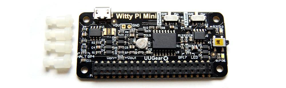
4 What is Witty Pi (Mini)? Witty Pi is small extension board that can add realtime clock and power management to your Raspberry Pi. After installing Witty Pi on your Raspberry Pi, you get some amazing new features: Gracefully turn on/off Raspberry Pi with single tap on the switch. Fully cuts power for Raspberry Pi and all its USB peripherals after shutdown. Raspberry Pi knows the correct time, even without accessing the Internet. You can schedule the startup/shutdown of your Raspberry Pi. You can even write a script to define complex ON/OFF sequence. When the OS loses response, you can long hold the switch to force power cut. Witty Pi supports all Raspberry Pi models that has the 40-pin GPIO header, including A+, B+, 2B, Zero and 3B. Witty Pi Mini is a new member in Witty Pi family. It has same features with Witty Pi Mini and is much smaller (phat shape). Comparing to Witty Pi Mini, Witty Pi Mini uses a super capacitor (0.08F, or 80000uF) for realtime clock off-power time keeping, and use two surface mounted switch to replace the red and blue jumpers in Witty Pi Mini. Thanks to the small dimension (65mm x 30mm x 4mm), Witty Pi Mini is very suitable to be used on Raspberry Pi Zero (V1.2, V1.3 or W), although it could also be used on other models. The picture below shows how Witty Pi Mini looks like: 1
 Red LED as power indicator, when Raspberry Pi is on. 5) Tact switch to turn on/off Raspberry Pi. 6) White LED as action indicator. 7) 2x20-pin header (connects to Raspberry Pi).")
5 1) Micro USB connector as DC 5V power in 2) Configure if Raspberry Pi should be turned on when power connected 3) Configure if dummy pausing load should be turned on. 4) Red LED as power indicator, when Raspberry Pi is on. 5) Tact switch to turn on/off Raspberry Pi. 6) White LED as action indicator. 7) 2x20-pin header (connects to Raspberry Pi). 8) Super capacitor (0.08F, or 80000uF) for off-power time keeping. 9) Unpopulated connector as DC 5V alternative power input. What is in the Package? Each Witty Pi Mini package contains: Witty Pi Mini board x 1 M2.5 x 10mm plastic screw x 4 4mm spacer x 4 M2.5 plastic nut x 4 2
6 3
7 Witty Pi Mini Specifications Dimension: Weight Realtime Clock Chip 65mm x 30mm x 4mm 9g (net weight) DS3231SN (datasheet) Red LED: lights up when Raspberry Pi gets powered. LED Indicator White LED: lights up for a few seconds when a shutdown command is received, or blinks when Witty Pi Mini is standing by. Connector 20x2 surface-mounted header with 2.54 mm pitch and 2mm plastic height. Micro USB female connector as 5V DC input. Time Keeping Using 0.08F super capacitor as time keeping power source. Allows about 17 hours off-power time keeping. Power In Output Current DC 5V via micro USB, or via the alternative power input connector (unpopulated). Maximum 2A for Raspberry Pi and its peripherals Standby Current Operating Temperature Storage Temperature Humidity ~ 5mA with dummy load turned off (default) ~7mA in average with dummy load turned on -30 ~80 (-22 F~176 F) -40 ~85 (-40 F~185 F) 0~80%RH, no condensing 4
8 Before Installation If you have installed Raspbian Jessie by directly flash the OS image into SD card, you can skip reading this section. You will need to installed the OS on the SD card first. We recommend NOT to use NOOBS, instead download the Raspbian image and directly flash it into your SD card (tutorial is here). The process could be faster and you will not have the problem caused by the NOOBS boot menu (read on for details). The software of Witty Pi has been tested under Raspbian Jessie and Raspbian Stretch. Raspbian Wheezy should also work, but it is better to use Jessie or Stretch as it will be much easier to install Qt 5, which is required by the (optional) GUI of the software. The software of Witty Pi might also work on other operating systems with or without modification. The software is written in BASH, so it could be easily modified by the customers to support other OS. However, at lest for now, only Raspbian Stretch, Jessie and Wheezy are officially tested. You should have mind preparation that tweaking might be needed when using Witty Pi Mini on other operating systems. If you have installed the OS with NOOBS, please make sure to skip the boot menu. Otherwise the boot menu will postpone the booting long enough to make Witty Pi Mini think the system is down and then cut the power (so your Raspberry Pi will not boot). Here is how to skip the NOOBS boot menu: you insert your SD card to your PC (use a SD card reader if your PC doesn t have SD card slot), open the RECOVERY partition and create a text file named autoboot.txt there. Edit it and put this into the file: boot_partition=6 It tells NOOBS to boot from the partition who is numbered 6. It is usually the case when you installed only one OS on the SD card (more details could be found here). If you have multiple OS installed, you can run sudo fdisk l command to find the partition to boot with. Remarks: there is a regression on NOOBS V2.2 and V2.3, so the trick above will not work on (at least) these two versions (details here). We hope it could be fixed soon, meanwhile you can use NOOBS V2.1 to avoid this problem (download from here), or even better, do not use NOOBS and directly flash the OS into the SD card. 5
9 Software Installation We strongly recommend to install the software for Witty Pi Mini BEFORE physically mount Witty Pi Mini on your Raspberry Pi. Witty Pi Mini uses the same software with Witty Pi 2. You will need to have your Raspberry Pi connected to the Internet. The installation will be very simple if you run our installing script. The wiringpi utility is required by the software so the script will install it for you, if you don t have it installed yet. First step is to run this command in your home directory: pi@raspberrypi ~ $ wget If your Raspberry Pi has internet connection, it will immediately download the script from our website, and you will then see the installwittypi.sh script in your home directory. Then you just need to run it with sudo: pi@raspberrypi ~ $ sudo sh installwittypi.sh Please notice that sudo is necessary to run this script. This script will automatically do these tasks in sequence: 1. Enable I2C on your Raspberry Pi 2. Install i2c-tools, if it is not installed yet 3. Configure Bluetooth to use mini-uart (Raspberry Pi 3 only) 4. Install wiringpi, if it is not installed yet 5. Install Witty Pi programs, if they are not installed yet 6. Remove fake-hwclock and disable ntpd daemon 7. Install Qt 5, if it is not installed yet (it is optional, and is for Jessie only) The fake-hwclock package is no longer needed as you have a real hardware clock now. Removing fake-hwclock package can avoid some potential problems (e.g. this one). Also the ntpd daemon should be disabled to avoid corrupting the RTC time. Disabling ntpd will not affect the NTP time synchronization as Witty Pi software will explicitly query NTP time and then update to system and RTC. 6


10 The Qt 5 installation is for the GUI only. If you don t plan to use it, you can skip this step for now, as Qt 5 installation will take a while. You can also manually install these packages and make those configurations, if you prefer to. After the installation, please remember to reboot your Raspberry Pi, so the Realtime clock I2C hardware will be loaded correctly. You will see a new wittypi directory, and it contains 5 runnable files: pi@raspberrypi ~ $ cd wittypi pi@raspberrypi ~ /wittypi $ ls daemon.sh init.sh synctime.sh runscript.sh utilities.sh wittypi wittypi.sh Although the daemon.sh is runnable, you should not run it manually. The installing script has registered it into /etc/init.d and it will run automatically after the start up. The synctime.sh script is not suppose to be manually run either, it will run automatically at about one minute after the start up. It will copy the time from Raspberry Pi system to RTC if you have never set the RTC time before. If RTC has correct time and your Raspberry Pi hasn t (because of the lacking of Internet), it will copy the RTC time to your Raspberry Pi system. The runscript.sh script is the one who takes charge of the schedule script running. Usually you don t need to run it manually, as it will be executed after the system is up. If there is a schedule script in use, it will schedule the next shutdown and next startup, according to the schedule script. The wittypi.sh is the software that allows you to configure your Witty Pi interactively. You can use it to copy time between Realtime clock and the system, and schedule the time for auto shutdown and/or startup. Please see the Software Usage chapter for more information. The wittypi is the GUI version of wittypi.sh, it requires desktop environment and Qt 5 to run. 7


11 Now the software has been installed, and you will need to physically mount Witty Pi Mini on your Raspberry Pi. Software Update/Uninstallation If you want to update the software to newer version, you don t have to uninstall it first. Just remove or rename your wittypi directory and repeat the installing process, then you are all set. pi@raspberrypi ~ $ mv wittypi wittypi.bak pi@raspberrypi ~ $ wget pi@raspberrypi ~ $ sudo sh installwittypi.sh If you prefer to completely remove the software, besides removing the wittypi directory, you should also remove the /etc/init.d/wittypi file. There are some dependencies (such as wiringpi, i2c-tools etc.), who are installed during the software installation. In the major of cases you don t have to remove them, but if you wish, you can check the content of installwittypi.sh script and do the reverse. 8
, you will need to solder the 20x2 pin male header on it first, or you can buy one with the header soldered already.")

12 Mounting Witty Pi Mini on Raspberry Pi Zero If you want to use Witty Pi Mini on Raspberry Pi Zero (V1.2, V1.3 or W), you will need to solder the 20x2 pin male header on it first, or you can buy one with the header soldered already. You can simply mount Witty Pi Mini on your Raspberry P Zero s 40-pin header, and it can work just like that. However, if you wish, you can use the plastic screws, spacers and nuts in the package to tightly mount Witty Pi Mini on your Raspberry Pi Zero. Please make sure NOT to put Witty Pi Mini up side down, the 40 pins should connect to the female header via the holes underneath, as shown in figure below. You will need to connect the power supply to the micro USB connector on Witty Pi Mini to make it work. Or you can power it via the (unpopulated) alternative power input connector. 9

.")
13 Mounting Witty Pi Mini on Other Raspberry Pi Models Other Raspberry Pi models (A+, B+, 2B and 3B) have the 40 pin header soldered already, so it is possible to directly mount Witty Pi Mini over them. However, because of the existence of display connector, you will not be able to firmly connect them. In order to make reliable connection, we suggest to use a stacking pin header (not included in the package). The 40 extra long pins on stacking header should reach the female header via the holes on the back of Witty Pi Mini. You can then place a steel ruler (or something 10


14 similar) between the two rows of pins and push Witty Pi Mini until it reaches the plastic of the stacking header, as shown in figure below: After mounting Witty Pi Mini on your Raspberry Pi, and connect the power supply to the micro USB connector on Witty Pi Mini, you can see the white LED blinking, which means it is standing by. Now your Witty Pi Mini is ready to go. If you want to take off the stacking header from Witty Pi Mini, the proper way is to put your Witty Pi Mini upside down, let the 40 pins contact a flat surface, hold the two edges and press down. That way the stacking header will be taken off safely. See the figure below: 11

15 Software Usage You can either run the wittypi.sh or wittypi (GUI executable), and they have (almost) the same functionality. If you are running desktop environment, you can go to the wittypi folder in your home directory, and double-click the wittypi file. When you are asked whether to execute it, choose Execute to continue. The wittypi.sh is a bash script, and you can run it with: pi@raspberrypi ~/wittypi $ sudo./wittypi.sh Please notice that sudo is required. Once the script is run, it will tell you the system time and RTC (Realtime clock) time, so you can decide how to copy the time. It also tells you the current temperature around your Raspberry Pi. 12


16 ~/wittypi $ sudo./wittypi.sh ================================================================================ Witty Pi - Realtime Clock + Power Management for Raspberry Pi < Version 2.55 > by UUGear s.r.o. ================================================================================ >>> Current temperature: C / F >>> Your system time is: Tue 12 Jul :46:15 CEST >>> Your RTC time is: Tue 12 Jul :46:16 CEST Now you can: 1. Write system time to RTC 2. Write RTC time to system 3. Synchronize time 4. Schedule next shutdown 5. Schedule next startup 6. Choose schedule script 7. Reset data Exit What do you want to do? (1~8) The program gives you 8 options, and you can input the number and press ENTER to confirm. 1. Write system time to RTC This option will copy the time from your Raspberry Pi system to the Realtime clock on Witty Pi. This option should be used when you find the system time is correct (may get synchronized from Internet) and RTC time is not. If you are running the GUI, you can click the button shown on the right to finish the same task. 2. Write RTC time to system 13
17 This option will copy the time from the Realtime clock on Witty Pi Mini to your Raspberry Pi system. This option should be used when you find the RTC time is correct while the system time is not. If you are running the GUI, you can click the button shown on the right to finish the same task. 3. Synchronize time If you choose this option, it will run the synctime.sh script explicitly, which should have been executed once after the system is up. This script will detect if Internet is connected, and apply NTP time to both system and RTC. The flow chart below shows what this script actually do: 14

18 Start RTC time is good? Y Write RTC time to system N N System time is newer than RTC? N Internet connected? Y Force NTP time update to system Y Write system time to RTC End If you are running the GUI, there is no such a button to do exactly the same. But if you want to write NTP time to both system and RTC, you can use this button: 4. Schedule next shutdown This option allows you to specify when your Raspberry Pi should shutdown 15
19 automatically. Please notice the input format should be DD HH:MM. DD means the day in the month, HH is the hour, MM is the minute. All these should be 2 digits and 24-hour system is used. Here you can not specify the second. This is a hardware limitation on the RTC chip, and only day, hour and minute could be specified for scheduled shutdown. You can use?? as wildcard, which gives you the possibility to make a repeatable schedule. Please see the table below: Repeatable Shutdown Schedule Day (dd) Hour (HH) Minute (MM) Result?????? Minutely Schedule (DON T USE IT!)???? Number Hourly Schedule?? Number Number Daily Schedule Please don t use????:?? to schedule the next shutdown, or your Raspberry Pi will keep being shutdown and you hardly have a chance to change this setting (unless you remove the battery and force RTC to forget it). According to the hardware limitation, not all patterns with wildcards are supported. The rule is: wildcards have to show up from let to right, and there is no number between two wildcards. So????:38 is OK, while?? 16:?? is not supported. Here are some examples of scheduling the shutdown: 15 21:45 means 9:45 at night, on 15 th in this month.?? 23:30 means 23:30 at night everyday (daily schedule)????:15 means the 15th minute every hour (hourly schedule) If you are running the GUI, you can specify the next shutdown time by clicking the Edit button in the row: 16
20 5. Schedule next startup This option allows you to specify when your Raspberry Pi should startup automatically. Please notice the input format should be DD HH:MM:SS, DD means the day in the month, HH is the hour, MM is the minute and SS is the second. All these should be 2 digits and 24-hour system is used. Different than the shutdown scheduling, you can specify the second here. You can also use?? as wildcard, which gives you the possibility to make a repeatable schedule. Please see the table below: Repeatable Startup Schedule Day (dd) Hour (HH) Minute (MM) Result?????? Minutely Schedule???? Number Hourly Schedule?? Number Number Daily Schedule According to the hardware limitation, not all patterns with wildcards are supported. The rule is: wildcards have to show up from let to right, and there is no number between two wildcards. So????:??:12 is OK, while?? 15:??:25 is not supported. If you input an unsupported pattern, Witty Pi Mini will try to change it to the closest one that could be supported. You will see the message on the console. Here are some examples of scheduling the startup: 15 07:30:00 means 7:30 in the morning, on 15 th in this month.?? 23:30:00 means 23:30:00 at night everyday (daily schedule)????:15:00 means the 15th minute every hour (hourly schedule)????:??:05 means the 5th second every minute (minutely schedule) If you are running the GUI, you can specify the next startup time by clicking the Edit button in the row: 17
21 6. Choose Schedule Script What if you want to define a complex ON/OFF sequence for your Raspberry Pi? The answer is schedule script. A schedule script (.wpi file) defines a loop, with all states and their durations inside. By automatically running runscript.sh after booting, Witty Pi Mini will automatically schedule the next shutdown and next startup for you, and hence a complex ON/OFF sequence could be achieved. After you select the Choose schedule script option, it will list all schedule scripts in the schedules folder. You can choose one, and then Witty Pi Mini will take care of the rest. If you want to confirm what the script is doing, you can check the schedule.log file in the ~/wittypi directory, when your Raspberry Pi is on. If you are running the GUI, you can click the Choose button and select the schedule script you need. After selecting the schedule script, it will be displayed as in use, and you can hover your mouse cursor on it to see the content of current schedule script. You may also click the Clear button to terminate the usage of schedule script. If you want to create your own schedule script, please read the Making Schedule Script chapter. 7. Reset Data If you want to erase the data you already set into Witty Pi Mini (scheduled startup time, scheduled shutdown time, currently used schedule script), you can choose this option. Once you select this option, the software will display a sub menu, which allows you to: Clear auto startup time: The auto-startup time will be erased and Witty Pi Mini will not auto-start your Raspberry Pi. 18
22 Clear auto shutdown time: The auto-shutdown time will be erased and Witty Pi Mini will not auto-shutdown your Raspberry Pi. Stop using schedule script: The schedule.wpi file will be removed. Perform all actions above: Clear all scheduled times and remove the schedule.wpi file. If you are running the GUI, there is no such a button to clear all those data. However you can clear them one by one, by clicking the Clear button in specific row. 8. Exit Selecting this option will simply exit the software and return to the console. If you are running the GUI, just close the GUI window to exit. 19
23 How Schedule Script Works? A schedule script defines a serial of ON/OFF states and specify the duration of each state. At the end of each state, there should be a scheduled shutdown (for ON state) or startup (for OFF state). All states in the schedule script will be executed in sequence and repeatedly, until the END time is reached. Start File schedule.wpi exists? Y N End Y Reached END time? N Schedule next shutdown and startup Find current and next state in the loop Every time your Raspberry Pi wakes up, it has a chance to run the runscript.sh file, which loads the schedule script ( schedule.wpi file). If the current time doesn t reach the END time defined by the schedule script, the next shutdown and next startup will be scheduled automatically. When your Raspberry Pi is wakened at scheduled startup time, it will repeat this process and schedule the next shutdown and startup. Although a schedule script only defines a few ON/OFF states, they could become many ON/OFF states in reality. 20


24 Please keep in mind that, running the same schedule script at different moment may get different result, as the runscript.sh will search and find the proper state according to current time. When the runscript.sh is executed, if the current time is located at an OFF state instead, it will take the next ON state as the current state, as it knows Raspberry Pi is currently ON. 21
25 Make Schedule Script A schedule script is a text file with. wpi file extension. You can use any text editor to create and edit it. In the major of cases, using nano will be very convenient. Below is a very simple schedule script and it will keep your Raspberry Pi on for 5 minutes in every 20 minutes. # Turn on Raspberry Pi for 5 minutes, in every 20 minutes BEGIN :00:00 END :59:59 ON M5 # keep ON state for 5 minutes OFF M15 # keep OFF state for 15 minutes Like many other scripting languages, Witty Pi s schedule script also uses # to make single line comment. The first two lines define the time range for executing the script. Please make sure to use the correct time format (YYYY-mm-DD HH:MM:SS). You can use one or more white characters (space or tab) between BEGIN/END and the time string. The rest of the script defines the states in the loop. It could be ON or OFF, and you should define at least one ON and one OFF states in the loop. The ON and OFF states are used in pair. You should also specify the duration of each state. You can do so by putting one or more parameters after ON/OFF text, separated by space or tab. Each parameter starts with a capital letter and follows by a number, where the capital letter is the unit of time: D = Days (D2 means 2 days) H=Hours (H3 means 3 hours) M=Minutes (M15 means 15 minutes) S=Seconds (S30 means 30 seconds) For example, if you wish to define an ON state for one and a half hour, you can write: ON H1 M30 When the script engine executes this line, it will actually schedule a shutdown at the 22
26 end of the ON state. If you wish to define an OFF state for two days, you can write: OFF D2 When this line gets executed, a startup will be scheduled at the end of the OFF state. Sometimes you may want to skip certain scheduling of shutdown/startup, and let your own program to do the job. This can be achieved by using the WAIT syntax. For example: ON M15 WAIT This will keep your Raspberry Pi ON and no shutdown will be scheduled after 15 minutes, because there is a WAIT at the end of the line. The parameter M15 is here only to make sure the next OFF state can be calculated correctly and next shutdown can be scheduled properly. Once you use WAIT in the ON state, you are responsible for the shutdown of your Raspberry Pi. Also if you use WAIT in the OFF state, you will need to turn on your Raspberry Pi (manually or via external electronic switch). After installing the software, there are some schedule scripts in the schedules directory, and they all have comments inside to explain themselves. You can take them as example to learn how to create the Witty Pi schedule script. Using Schedule Script Generator You can use our web application to create your schedule script. Just simply open this URL in your web browser and you are ready to go: This web application allows you to visually create the schedule script, it immediately generate the final schedule script (on the right). You can also click the Run button to preview how the schedule script will work. Alternatively, you can click the Run at button and specify the moment to run the script. With this preview engine, you can verify your schedule script without waiting for hours or even days to see how your Raspberry Pi will be turned on and off. 23

27 Although the schedule script doesn t support looping, this web application allows you to repeat the specific ON/OFF states for certain times, and it will generate the schedule script with those ON/OFF states duplicated for certain times. Advanced Usage of Schedule Script 24
28 Although the schedule script can be chosen by wittypi.sh, you can use it without the help from wittypi.sh. Just copy the schedule script file to ~/wittypi/schedule.wpi and then run sudo./runscript.sh in the ~/wittypi directory, the script will start to work. This allows you to use schedule script as an interface, to integrate other tools with Witty Pi Mini together. For example, you can create your own tool to visually create a schedule script, or remotely generate the schedule script via a web interface. 25

29 Hardware Configuration and Hackings There are two small switches on the board, and they allow you to make some customization on your Witty Pi Mini. Default On/Off The switch on the left has label Default can decide if you Raspberry Pi gets powered immediately when you connect the 5V power supply to Witty Pi Mini. By default, this switch is set to Off, so you have to tap the button once to power on your Raspberry Pi. Pulsing Dummy Load The switch on the right has label D.Load, witch stands for Dummy Load. This switch is to turn on/off the pulsing dummy load. The dummy load may be useful if you are using power bank to power your Witty Pi Mini + Raspberry Pi. When dummy load is on, it will draw certain current (~200mA) for very short period (~50ms), with a fixed interval (~5 seconds), which could be useful to keep your power bank alive with low average current consumption. Please notice that, different power bank may have different current thresholds to keep them on. Witty Pi Mini s pulsing dummy load may not necessarily meet all their requirements. If you find out that your power bank needs higher peak current to keep alive, you can change the resistor R20 (20 Ohms) to a smaller one. How the pulsing dummy load works? You may ask. The idea behind is quite straightforward. The SA555 chip will generate the pulsing signal, which is routed to 26
.")
30 the right lead of the switch K3, as shown below: By default, the dummy load is off. If you turn the switch to the right side, the pulsing signal will be connected to a MOSFET, and controls the on/off of load (R20). When dummy load switch is on, the pulsing signal connects to the gate of a N-MOSFET. When the signal goes high, the MOSFET is conducted and the current will be consumed (via the resistor R20). The peak current can be calculated with this formula: I max = V cc / (R + R ds ) Where Vcc is 5V, R is the load resistor (R20) and R ds is the resister between the drain and source of the N-MOSFET, which is a few Ohms. Some power banks have relatively complex algorism to decide whether they should cut off the power. Some of them even calculate the integration of current to make sure certain current should be consumed when the power is on. For those power banks, this pulsing dummy load trick may not work well. In this case you might want to use a simple resistor to be a real load to drain enough current and keep the power bank alive. 27

.")
31 You can connect the resistor between the 5V and the ground, and you can make use of the unpopulated alternative power input connector. White LED Indicator By default, the white LED indicator is driven by GPIO-17 pin. If you want to change that, you will need to make some hackings with your soldering iron (at your own risk). You can remove the resistor R27 (0 Ohm) and then connect the pad with LED label to the GPIO pin you want. 28
.")

32 Halt Pin By default, GPIO-4 pin is the pin that receives signal to shutdown your Raspberry Pi. If you want to change that, you will need to make some hackings again (at your own risk). You can remove the resistor R26 (0 Ohm) and then connect the pad with HALT label to the GPIO pin you want. You will also need to modify the software a little bit to use different GPIO pins. More details here: Testing Pads on the Back On the back of Witty Pi Mini board, there are 6 testing pads, and each of them has a label beside. These testing pads were for product testing, but you can solder wires on them and them for extension and integration purpose. 29
33 Switch It is the signal line that connects to the switch (button) on Witty Pi Mini. If you want to connect your own (2-lead) switch, just wire the two leads to Switch and GND pads. Alternatively, if you wish to trigger Witty Pi Mini with external signal, you can use a N-channel MOSFET to achieve this: The signal should be a positive pulse, and the pulse length should be longer than 300ms. Processing a pulse will be equal to taping the switch once, so it will turn on your Raspberry Pi if your Pi is off, or turn off your Raspberry Pi if your Pi is on. GND It is the ground of the circuit board and all voltages are based on it. LED It is connected to the anode of the white LED. You can use this test pad to connect your own LED, but don t forget to put a 1K resistor in serial. 30
34 Vbat This pin directly connects to the + terminal of the super capacitor. By measuring the voltage of this pin, you know if the capacitor is fully charged (3.3V means full). If you want to have a (much) longer off-power time keeping duration, you can connect your own 3V battery to this pad. If you use the rechargeable battery, you just need to connect it directly to Vbat and GND pads. Witty Pi Mini will charge this battery with trickle current, when the power supply is connected. If you use non-rechargeable battery, you will need to use a diode to make sure the battery will be discharged only. INT It is the interrupt signal that generated by the RTC alarm. It is in 5V level and has HIGH state (5V) by default. If any alarm occurs (scheduled startup or shutdown), it goes to LOW state (0V), and this state will be cleared once Witty Pi Mini s software detects and process it. If the alarm occurs when Witty Pi Mini is not powered, the INT pad will stay in LOW state. When power is back online, your Raspberry Pi will boot immediately. 31
35 Vout This pad is actually connected to the +5V pin on Raspberry Pi, which is the output voltage of Witty Pi Mini board. By detecting its voltage, you will know if your Raspberry Pi is in ON state. The red LED indicator on board is also connected to this pad (via a resistor). 32
36 Witty Pi Mini Log Files In the directory that you install your Witty Pi software, you can find two log files: schedule.log and wittypi.log. If you need our help for solving a problem, please kindly put the log files in attachment too. This will help us to help you better. The schedule.log file contains the history of schedule script executions. Here you can see how the next shutdown and startup get scheduled. If you saw unexpected schedule script behavior, this log should be the first file to check. The wittypi.log file records the history of all Witty Pi activities. If you think your Witty Pi doesn t behave right, this log file might provide more information for debugging. The time-stamp in the log file is always the system time, instead of the RTC time. During the booting, the first log written by Witty Pi's software is "Witty Pi 2 daemon (v2.55) is started.", but its time-stamp might not be correct as the system time has not been updated by RTC yet (or if it is correct already, maybe the ntpd daemon updates the time earlier, when Internet is connected). You will see the correct time after the [ :10:14] Witty Pi 2 daemon (v2.55) is started. [ :10:16] Synchronizing time between system and Witty Pi... [ :10:16] Writing RTC time to system... [ :05:13] Done :-) RTC time has been written to the system. For example: This correct time-stamp shows up in the line for "Done :-)", so this startup happened at 14:05. When the booting is done, the last log written by Witty Pi software is "Pending for incoming shutdown command...". If there is Internet connection, the NTP time will be applied to the system and RTC later. 33
 on Witty Pi Mini via I 2 C protocol. The DS3231 chip has a fixed I 2 C address: 0x68.")


37 Frequently Asked Questions (FAQ) What I2C Address is Used by Witty Pi Mini? Raspberry Pi communicates with the RTC chip (DS3231) on Witty Pi Mini via I 2 C protocol. The DS3231 chip has a fixed I 2 C address: 0x68. If you have Witty Pi Mini connected to Raspberry Pi and run sudo i2cdetect -y 1 in the console, you will see this: pi@raspberrypi ~ $ sudo i2cdetect -y a b c d e f 00: : : : : : : : pi@raspberrypi ~ $ This address is fixed and you can never change it. If you want to use other I 2 C devices on your Raspberry Pi, please make sure they have different I 2 C addresses. 34
38 What GPIO Pins Are Used by Witty Pi Mini? The GPIO pins used by Witty Pi Mini are marked with green color in the table below. GPIO (BCM) Name Physical Name GPIO (BCM) 3.3V 1 2 5V 2 SDA V 3 SCL GND 4 GPIO TXD 14 GND 9 10 RXD GPIO GPIO GPIO GND 22 GPIO GPIO V GPIO MOSI GND 9 MISO GPIO SCLK CE0 8 GND CE1 7 0 SDA SCL GPIO GND 6 GPIO GPIO GPIO GND 19 GPIO GPIO GPIO GPIO GND GPIO As you can see in the table, Witty Pi Mini uses GPIO-4, GPIO-17, GPIO-2 (SDA 1) and GPIO-3 (SCL 1). The usage of GPIO-4 and GPIO-17 are customizable. If you want to use other GPIO pins to do their job, you can follow this tutorial: 35
39 GPIO-2 and GPIO-3 are for I 2 C communication between Raspberry Pi and the RTC chip (DS3231). I 2 C devices are identified by I 2 C address, and they can share the I 2 C pins as long as they have different I 2 C addresses. Witty Pi Mini doesn t actually use the TXD pin (it only monitors it). So using serial port for data transaction will not be a problem. Is Witty Pi Mini Compatible with Other Hardware? Please understand that we might not have the hardware you have on hand, and even if we have, it is difficult for us to make tests on all these hardware with Witty Pi Mini. Fortunately, it is not that difficult to figure out the answer by yourself. Basically you just need to consider the I 2 C address and GPIO pins used by the Other Hardware. If the Other Hardware uses 0x68 I 2 C address, it will be a confliction with Witty Pi s RTC chip and you can not use it with Witty Pi together. If the Other Hardware doesn t use any GPIO pin that used by Witty Pi, and it doesn t use 0x68 I 2 C address, then it should be compatible with Witty Pi. If you have no idea which I 2 C address (if applicable) or GPIO pins are used by the Other Hardware, please contact its developer, as they certainly know their hardware and can provide you accurate information about it. Witty Pi Mini dose not boot? Some customers meet the situation that Witty Pi Mini only boot Raspberry Pi for a few seconds, and then shutdown Raspberry Pi with or without lighting the white LED first. Remarks: you may need to disconnect Witty Pi Mini from your Raspberry Pi, and power on Raspberry Pi only for troubleshooting. There are some possible reasons that can cause this kind of problem: 1. The OS was installed via NOOBS, and boot menu was not skipped If you have a display connected to your Raspberry Pi during the booting, and you have not saw the Raspberry Pi logo before Witty Pi Mini cuts the power, then it is the case. Please read the Before Installation section first, and make sure to skip the NOOBS boot menu. Otherwise the boot menu will delay the booting, and hence the TX pin doesn t raise fast enough, so Witty Pi Mini thinks the OS is down and cuts the power directly. 36
40 2. Serial port is disabled or misconfigured The TX pin in serial port should quickly go to ~3.3V when system is up. If for any reason, that TX pin has not realized to ~3.3V in given time frame (a few seconds), Witty Pi Mini will think the OS is down and will cut the power directly. If disconnecting Witty Pi Mini and powering Raspberry Pi directly can allow you to enter the system, you can run gpio readall to check the pin state. The normal pin state should look like this: If the serial port is disabled or misconfigured, you might see something like this: If you are not using Raspberry Pi 3, it is most probably because the serial port is disabled. If in the /boot/config.txt file, you can find enable_uart=0, please change it to enable_uart=1 and reboot. If you are using Raspberry Pi 3, you will need to move the Bluetooth to 37
41 mini-uart(ttys0) and restore UART0/ttyAMA0 over GPIO 14 and 15. You can achieve this by adding dtoverlay=pi3-miniuart-bt to the /boot/config.txt file. You will also need to add core_freq=250 to the /boot/config.txt file to make sure Bluetooth can work properly. Don t forget to reboot to let the changes take effect. 3. Software does not run automatically after Raspberry Pi system is on After installing the software, you will have daemon.sh, synctime.sh and runscript.sh scripts in the directory that has software installed. These scripts should be executed automatically after the operating system is up. If these scripts are not automatically executed for any reason, Witty Pi Mini will cut the power of Raspberry Pi, without lighting up the white LED. In this case, the first place to check is the /etc/init.d/wittypi file, and there is possibility that it contains wrong paths to these scripts. If you are running a special distribution of OS, make sure to check if the commands in the /etc/init.d/wittypi file do exist in the system, or it will fail silently. For example, Minibian doesn t have sudo command. 4. Witty Pi Mini is unexpectedly woken up by shutdown alarm This could happen, after you scheduled a shutdown in the future, and then Witty Pi Mini lost power connection. Raspberry Pi is off ungracefully and later the power connection is resume. If the shutdown alarm occurs when Raspberry Pi is still off, it will wake it up, which is unexpected. The software will detect this situation and shutdown your Raspberry Pi immediately, and you will see the white LED lights up before the shutdown. Next time when you turn on your Raspberry Pi, it will be normal again, and you can find this message in the log, for previous shutdown: Seems I was unexpectedly woken up by shutdown alarm, must go back to sleep... Sometimes the same case can happen when you tap the button to turn on your Raspberry Pi, if the shutdown alarm occurs during the time that no power supply was connected. You may ask, how comes the shutdown alarm could act like a startup alarm? This is specific to Witty Pi 2 and Mini. Witty Pi 2 and Mini uses the same RTC chip (DS3231), which is way better than the one used in on Witty Pi (DS1337). The downside however, is the better RTC chip merges two alarm pins into one. Hence without turning on your Raspberry Pi and check the RTC registers, there is no way to know if the current alarm is a shutdown alarm or not. 5. GPIO-4 pin doesn t reach a stable status in given time 38
42 After the system is on, GPIO-4 pin should be in input mode and gets internally pulled up. However, during the startup the GPIO-4 pin could be unstable. In the daemon.sh script, the GPIO-4 listener will be started once the pin state hasn t changed for 10 seconds. Once the GPIO-4 listener is started, any action that pulls down GPIO-4 will be regarded as a shutdown command. So if GPIO-4 pin doesn t really get stable after the given 10 seconds, Witty Pi will take it as a shutdown command, lights up the white LED and then shutdown the system. There are many factors that might cause the GPIO pin unstable, and the most common one is the power supply. If your power supply is not strong enough, during the booting its voltage may drop from time to time, which may also make the GPIO pin voltage drop, and trigger the GPIO-4 listener to shutdown your Raspberry Pi. If it is the case, you don t have to replace the power supply. Just try to delay the starting of GPIO-4 listener, and in the major of cases it will help. You can modify the "daemon.sh" script, in line 66: while [ $counter -lt 5 ]; do Try to change the number 10 to 25. The bigger number you use, the later the GPIO-4 listener will be started. This modification may workaround the problem. If it doesn t, it means your GPIO-4 is really pulled down (by software or hardware), and you can confirm that by measuring the voltage on GPIO-4 with a multimeter. By default, the GPIO-4 should be internally pulled up. If it gets pulled down, try to find out who does this and don t let it do this again, or you can use another pin to replace GPIO-4. 39
43 Revision History Revision Date Description Initial revision Add more content to explain schedule script 40
Zero2Go. User Manual (revision 1.03) Wide Input Range Power Supply for Your Raspberry Pi. Copyright 2017 UUGear s.r.o. All rights reserved.
 Wide Input Range Power Supply for Your Raspberry Pi. Copyright 2017 UUGear s.r.o. All rights reserved.") Zero2Go Wide Input Range Power Supply for Your Raspberry Pi User Manual (revision 1.03) Copyright 2017 UUGear s.r.o. All rights reserved. Table of Content Product Overview... 1 Product Details... 3 Package
Zero2Go Wide Input Range Power Supply for Your Raspberry Pi User Manual (revision 1.03) Copyright 2017 UUGear s.r.o. All rights reserved. Table of Content Product Overview... 1 Product Details... 3 Package
Zero2Go Omini. Wide Input Range, Multi-Channel Power supply for Raspberry Pi. User Manual (revision 1.01)
") Zero2Go Omini Wide Input Range, Multi-Channel Power supply for Raspberry Pi User Manual (revision 1.01) Copyright 2018 UUGear s.r.o. All rights reserved. Table of Content Product Overview... 1 What is
Zero2Go Omini Wide Input Range, Multi-Channel Power supply for Raspberry Pi User Manual (revision 1.01) Copyright 2018 UUGear s.r.o. All rights reserved. Table of Content Product Overview... 1 What is
PiRyte Mini ATX PSU Revision User Manual
 Revision 1.1.0 User Manual Overview Congratulations on your purchase of the PiRyte Mini ATX PSU! Please read this entire manual before using to ensure you receive maximum benefit from this board while
Manual of ET-LCD SW HAT
 ET- LCD SW HAT ET-LCD SW HAT is Board I/O that is specifically designed for connection with Board Raspberry Pi through Connector 40-PIN; this board includes LCD 16x2, SW, Buzzer, RTC DS3231 with Connector
PiRyte Mini ATX PSU Revision 1.0 User Manual
 Revision 1.0 User Manual Overview Congratulations on your purchase of the PiRyte Mini ATX PSU! Please read this entire manual before using to ensure you receive maximum benefit from this board while protecting
Power over Ethernet (PoE) Adaptor
 Adaptor") Power over Ethernet (PoE) Adaptor For the Raspberry Pi model B+, Pi2 and Pi3 User Manual www.circuitsurgery.com Page 1 of 6 Description N.B.: In this manual the term "Raspberry Pi" will refer to the Raspberry
Power over Ethernet (PoE) Adaptor For the Raspberry Pi model B+, Pi2 and Pi3 User Manual www.circuitsurgery.com Page 1 of 6 Description N.B.: In this manual the term "Raspberry Pi" will refer to the Raspberry
AlaMode User Manual Revision
 AlaMode User Manual Revision 1.0 www.wyolum.com info@wyolum.com 1 Introduction The AlaMode is an integrated Arduino compatible board. It is designed as versatile, general purpose data acquisition and control
Shack Clock kit. U3S Rev 2 PCB 1. Introduction
 Shack Clock kit U3S Rev 2 PCB 1. Introduction Thank you for purchasing the QRP Labs Shack Clock kit. This clock uses the Ultimate3S QRSS/WSPR kit hardware, but a different firmware version. It can be used
Prototyping Module Datasheet
 Prototyping Module Datasheet Part Numbers: MPROTO100 rev 002 Zenseio LLC Updated: September 2016 Table of Contents Table of Contents Functional description PROTOTYPING MODULE OVERVIEW FEATURES BLOCK DIAGRAM
Supplement for module D061 incl. ATMega128 Prozessor
 Supplement for module D061 incl. ATMega128 Prozessor V 1.3 16. March 2006 2006 by Peter Küsters This document is in copyright protected. It is not permitted to change any part of it. It is not permitted
Adding a Real Time Clock to Raspberry Pi
 Adding a Real Time Clock to Raspberry Pi Created by lady ada Last updated on 2016-11-03 01:44:48 AM UTC Guide Contents Guide Contents Overview Wiring the RTC Adafruit DS1307 Real Time Clock Assembled Breakout
LiFePO4wered/Pi product brief
 Introduction The is a high performance battery power system for the Raspberry Pi. It can power a Raspberry Pi for 1 to 3 hours (depending on model and load) from the battery and can be left plugged in
What is SmartUPS. Connections. Button and LED Indicator. SmartUPS User Guide
 SmartUPS User Guide What is SmartUPS SmartUPS is Uninterruptible Power Supply & Portable Power for Raspberry Pi. SmartUPS runs on 3 AA NiMH rechargeable batteries. Connections 1) Power connection (micro-usb):
Raspberry Pi GPIO Zero Reaction Timer
 Raspberry Pi GPIO Zero Reaction Timer Tutorial by Andrew Oakley Public Domain 1 Feb 2016 www.cotswoldjam.org Introduction This Python programming tutorial, shows you how simple it is to use an LED light
The Basic Counter. Hobby Electronics Soldering Kit. Instruction Guide
 The Basic Counter Hobby Electronics Soldering Kit Instruction Guide TM For the best outcome, follow each step in order. We recommend reading this guide entirely before you get started. Tools required:
A Hardware watchdog and shutdown button
 LinuxFocus article number 239 http://linuxfocus.org A Hardware watchdog and shutdown button by Guido Socher (homepage) About the author: Guido loves Linux because it is always interessting to discover
Building the FlipChip Tester
 Building the FlipChip Tester 1. Assembly of the Core Board You will need a fine low-wattage soldering iron and a Voltmeter. Take your time to solder the components on the Core Board. Better to spend a
9 Output Devices: Buzzers
 9 Output Devices: Buzzers Project In this project, you will learn how to connect and control LEDs (Light Emitting Diode) and a buzzer with the Raspberry Pi. Components In addition to your Raspberry Pi,
Arduino Uno. Arduino Uno R3 Front. Arduino Uno R2 Front
 Arduino Uno Arduino Uno R3 Front Arduino Uno R2 Front Arduino Uno SMD Arduino Uno R3 Back Arduino Uno Front Arduino Uno Back Overview The Arduino Uno is a microcontroller board based on the ATmega328 (datasheet).
keyestudio Keyestudio MEGA 2560 R3 Board
 Keyestudio MEGA 2560 R3 Board Introduction: Keyestudio Mega 2560 R3 is a microcontroller board based on the ATMEGA2560-16AU, fully compatible with ARDUINO MEGA 2560 REV3. It has 54 digital input/output
USER MANUAL FOR GS100/GS1003G
 USER MANUAL FOR GS100/GS1003G 1 Table of Contents 1. INTRODUCTION... 3 2. FEATURES... 3 3. OPERATION... 3 4.CONNECTION DETAILS... 4 5.CONFIGURATION... 5 5.1 Hyper Terminal Setting... 5 5.2 GS100 Configuration...
Grove Lightning Detector 0219-MOD1016G-01
 Features and Benefits: The is an Arduino and Raspberry Pi Grove compatible breakout board with a full set of connectors. No external antennas required! It is designed for use in Low Power applications
DIGITAL GAME CAMERA. Model DC-6SS
 DIGITAL GAME CAMERA Model DC-6SS CONTENTS: WELCOME... 2 GETTING STARTED... 3 MOTION DETECTOR... 4-8 CAMERA MENUS... 9-10 CONNECTING TO A COMPUTER... 11 TROUBLESHOOTING... 12 WARRANTY... 13 Leaf River Outdoor
Cygnos360 V2 Installation Manual
 Cygnos360 V2 Installation Manual VERSION 1.04. - MARCH, 2010 www.cygnos360.com Contents: Cygnos360 V2 Installation Manual... 1 1. What you need... 2 1.1. Tools... 2 2. Preparation... 3 2.1. Preparing the
User Manual. cmt-svr Startup Guide
 User Manual cmt-svr Startup Guide Table of Contents Chapter 1 Overview... 1 1.1 Specification... 1 1.2 Dimensions... 2 1.3 Connector pin designations... 3 1.4 USB host port and SD card slot... 3 1.5 Ethernet
ARDUINO YÚN Code: A000008
 ARDUINO YÚN Code: A000008 Arduino YÚN is the perfect board to use when designing connected devices and, more in general, Internet of Things projects. It combines the power of Linux with the ease of use
M4-ATX-HV 6-34V Intelligent ATX Power Supply
 M4-ATX-HV 6-34V Intelligent ATX Power Supply Installation Guide Version 1.0e P/N M4-ATX-HV-01 Before you start Please take a moment and read this manual before you install the M4-ATX-HV in your vehicle.
User Manual. cmt-svr Startup Guide
 User Manual cmt-svr Startup Guide Table of Contents Chapter 1 Overview... 1 1.1 Specification... 1 1.2 Dimensions... 2 1.3 Connector pin designations... 3 1.4 USB host port and SD card slot... 3 1.5 Ethernet
Mailbox Notification Service. Created by Adam Kohring
 Mailbox Notification Service Created by Adam Kohring Last updated on 2015-06-24 10:20:07 PM EDT Guide Contents Guide Contents Overview Parts List Adafruit Products Additional Products Print the Circuit
MP6500 Stepper Motor Driver, Digital Current Control
 This breakout board for the MPS MP6500 micro stepping bipolar stepper motor driver is Pololu s latest stepper motor driver. The module has a pinout and interface that are very similar to that of our popular
Propeller Project Board USB (#32810)
") Web Site: www.parallax.com Forums: forums.parallax.com Sales: sales@parallax.com Technical: support@parallax.com Office: (916) 624-8333 Fax: (916) 624-8003 Sales: (888) 512-1024 Tech Support: (888) 997-8267
Web Site: www.parallax.com Forums: forums.parallax.com Sales: sales@parallax.com Technical: support@parallax.com Office: (916) 624-8333 Fax: (916) 624-8003 Sales: (888) 512-1024 Tech Support: (888) 997-8267
Supplement for module D041 incl. ATMega8 Prozessor
 Supplement for module D041 incl. ATMega8 Prozessor V 1.4 16. March 2006 2006 by Peter Küsters This document is in copyright protected. It is not permitted to change any part of it. It is not permitted
Cygnos360 V2 Installation Manual
 VERSION 1.0. - OKTOBER, 2009 www.cygnos360.com Contents: 1. What you need...2 1.1. Tools...2 2. Preparation...3 2.1. Preparing the solder points...3 3. Installing in your Xbox360...4 3.1. Installing the
8051 Intermidiate Development Board. Product Manual. Contents. 1) Overview 2) Features 3) Using the board 4) Troubleshooting and getting help
 Overview 2) Features 3) Using the board 4) Troubleshooting and getting help") 8051 Intermidiate Development Board Product Manual Contents 1) Overview 2) Features 3) Using the board 4) Troubleshooting and getting help 1. Overview 2. Features The board is built on a high quality FR-4(1.6
8051 Intermidiate Development Board Product Manual Contents 1) Overview 2) Features 3) Using the board 4) Troubleshooting and getting help 1. Overview 2. Features The board is built on a high quality FR-4(1.6
P4M-400 User Manual > Introduction. Introduction
 P4M-400 User Manual > Introduction Introduction The P4M-400 is a module type of PHPoC product. Since PHPoC function is provided in module form, it is possible to implement the board suitable for user application.
RN-174 WiFly Super Module
 RN- WiFly Super Module Features Evaluation board for the RN- module Supports chip antenna (RN--C), PCB trace antenna (RN--P), wire antenna (RN--W), and U.FL connector for an external antenna (RN--U) Ultra-low
Ultra Short Installation Procedure of the UPS PIco HV3.0 Daemons. and UPS PIco HV3.0 broadcasting System
 Ultra Short Installation Procedure of the UPS PIco HV3.0 Daemons and UPS PIco HV3.0 email broadcasting System 1. Install Raspberry Pi Operation System (i.e. NOOBs) Disable the serial port (only if you
Gooligum Electronics 2015
 The Wombat Prototyping Board for Raspberry Pi Operation and Software Guide This prototyping board is intended to make it easy to experiment and try out ideas for building electronic devices that connect
7mAh Lithium Rechargeable battery provides 3 month of backup time. Two 22F Super Capacitors provide 40 seconds of backup time on 0.5A.
 Pi Cubes is DIY modular automation system for Home/HVAC Automation. It is based on the Raspberry Pi B+/A+ as well Raspberry Pi 2. It supports up to 24 I/O Points and up to 4 communication thermostats.
ARDUINO UNO REV3 Code: A000066
 ARDUINO UNO REV3 Code: A000066 The UNO is the best board to get started with electronics and coding. If this is your first experience tinkering with the platform, the UNO is the most robust board you can
1. USB to Serial cable driver installation instructions 2. Instructions for use with Raspberry Pi 3. Instructions for use with WRT54g and similar
 TechnoFix This document contains three sections: 1. USB to Serial cable driver installation instructions 2. Instructions for use with Raspberry Pi 3. Instructions for use with WRT54g and similar Please
C1182 Video Compression Module User Manual. Release Note: 1 st Release : Aug 01, 2012
 C1182 Video Compression Module User Manual Release Note 1 st Release Aug 01, 2012 General Description This is a series of camera modules which perform video compression and output video stream through
Introduction. LiFePO 4 wered/pi3
 Introduction The LiFePO 4 wered/pi3 is a high performance battery power system for the Raspberry Pi. It can power a Raspberry Pi for 1 to 9 hours from the battery (depending on Raspberry Pi model, attached
Pmod modules are powered by the host via the interface s power and ground pins.
 1300 Henley Court Pullman, WA 99163 509.334.6306 www.store. digilent.com Digilent Pmod Interface Specification 1.2.0 Revised October 5, 2017 1 Introduction The Digilent Pmod interface is used to connect
Instruction Manual for BE-SP3 Circuit. 10/21/07
 Page 1 of 54 Instruction Manual for BE-SP3 Circuit. 10/21/07 Page 1 Index: Page 2 BE-SP3 Circuit Specifications. Page 3-4 Intro to the BE-SP3. Page 5 Basics of serial to parallel. Page 6-7 ASCII Code.
BalloonSat Sensor Array
 BalloonSat Sensor Array The PICAXE-08M2 in the BalloonSat flight computer is a digital device. Being digital, it functions best with a series of on and off voltages and does not interact very well with
Manual iaq-engine Indoor Air Quality sensor
 Manual iaq-engine, Version 2.0 May 2011 (all data subject to change without notice) Manual iaq-engine Indoor Air Quality sensor Digital and analog I/O SMD type package Product summary iaq-engine is used
Application Note: AN0106. On-Board SPI Programming with Dediprog tools: End User Version
 4F., No.7, Ln. 143, Xinming Rd., Neihu Dist., Taipei City 114, Taiwan Application Note: AN0106 On-Board SPI Programming with Dediprog tools: End User Version (This document is provided to help users who
STANDALONE INTERFACES USB-DMX 512 & 1024 CHANNELS V.1.1
 STANDALONE INTERFACES USB-DMX 512 & 1024 CHANNELS V.1.1 SUMMARY Hardware technical specifications... 3 Front Face of the 512 / 1024 channels interfaces... 4 Side Faces of the 512 / 1024 channels interfaces...
University of Hull Department of Computer Science C4DI Interfacing with Arduinos
 Introduction Welcome to our Arduino hardware sessions. University of Hull Department of Computer Science C4DI Interfacing with Arduinos Vsn. 1.0 Rob Miles 2014 Please follow the instructions carefully.
OpenSprinkler v2.1u Build Instructions
 OpenSprinkler v2.1u Build Instructions (Note: all images below are 'clickable', in order for you to see the full-resolution details. ) Part 0: Parts Check Part 1: Soldering Part 2: Testing Part 3: Enclosure
Pi PoE Switch HAT Quick Start And FAQ. Getting started. Kit contents
 Pi PoE Switch HAT Quick Start And FAQ Getting started The Pi PoE Switch HAT is an add on board for the Raspberry Pi that brings the Switch technology together with PoE all in one fantastic package! You
ARDUINO MEGA ADK REV3 Code: A000069
 ARDUINO MEGA ADK REV3 Code: A000069 OVERVIEW The Arduino MEGA ADK is a microcontroller board based on the ATmega2560. It has a USB host interface to connect with Android based phones, based on the MAX3421e
Thunder Board 0240-THNDRBRD-DSBT
 ! Product Specification Features and Benefits: The is an Arduino and Raspberry Pi Grove compatible breakout board with a full set of connectors. No external antennas required! It is designed for use in
Display Real Time Clock (RTC) On LCD. Version 1.2. Aug Cytron Technologies Sdn. Bhd.
 On LCD. Version 1.2. Aug Cytron Technologies Sdn. Bhd.") Display Real Time Clock (RTC) On LCD PR12 Version 1.2 Aug 2008 Cytron Technologies Sdn. Bhd. Information contained in this publication regarding device applications and the like is intended through suggestion
Display Real Time Clock (RTC) On LCD PR12 Version 1.2 Aug 2008 Cytron Technologies Sdn. Bhd. Information contained in this publication regarding device applications and the like is intended through suggestion
Cygnos360 V2 Installation Manual
 VERSION 1.03 - JANUARY, 2010 www.cygnos360.com Contents:... 1 1. What you need... 2 1.1. Tools... 2 2. Preparation... 3 2.1. Preparing the solder points... 3 3. Installing in your Xbox360... 4 3.1. Installing
Arduino ADK Rev.3 Board A000069
 Arduino ADK Rev.3 Board A000069 Overview The Arduino ADK is a microcontroller board based on the ATmega2560 (datasheet). It has a USB host interface to connect with Android based phones, based on the MAX3421e
RaspiDigiHamClock. Raspberry Pi Amateur Radio Digital Clock. v WA4EFH R.Grokett
 RaspiDigiHamClock Raspberry Pi Amateur Radio Digital Clock v2018-07-08 WA4EFH R.Grokett Overview Amateur Radio Operators (aka HAM Radio) use 24 hour UTC (Universal Coordinated Time) for much of their operation.
PiJuice Quick Start Guide and FAQ. Getting started. Kit contents
 PiJuice Quick Start Guide and FAQ Getting started As one of the smallest systems around there are so many amazing things you could do with the Raspberry Pi if it was self-powered and portable. Introducing
AXE033 SERIAL/I2C LCD & CLOCK
 AXE033 SERIAL/I2C LCD & CLOCK The serial LCD and clock module allows microcontroller systems (e.g. PICAXE) to visually output user instructions or readings, without the need for a computer. This is especially
GPRS ADAPTER INSTALLATION AND USER MANUAL. for module version v2.24 and higher
 GPRS ADAPTER INSTALLATION AND USER MANUAL for module version v2.24 and higher Table of contents 1 Main function of the Adapter...3 2 System operation...3 2.1 Transmission through GPRS...4 2.1.1 Router
Chapter 2 Working Inside Desktop Computers and Laptops
 Chapter 2 Working Inside Desktop Computers and Laptops TRUEFALSE 1. When disassembling a computer, it's okay to stack circuit boards on top of each other as long as you follow ESD protection rules. (A)
Digital Design and Computer Architecture
 Digital Design and Computer Architecture Lab 6: C Programming Introduction In this lab, you will learn to program an ARM processor on the Raspberry Pi in C by following a tutorial and then writing several
TE-CDVR-4 & TE-CDVR-G User Manual. l ::: J TECH SUPPORT. MetraDealer.com
 TE-CDVR-4 & TE-CDVR-G User Manual ibeamusa.com MetraDealer.com techsupport@metra-autosound.com TECH SUPPORT l ::: J 800-253-8324 Hardware Guide Catalogue Chapter 1 Accessories and Interface... 1 1.DVR
AT42QT101X Capacitive Touch Breakout Hookup Guide
 Page 1 of 10 AT42QT101X Capacitive Touch Breakout Hookup Guide Introduction If you need to add user input without using a button, then a capacitive touch interface might be the answer. The AT42QT1010 and
OpenSprinkler v2.2u Build Instructions
 OpenSprinkler v2.2u Build Instructions (Note: all images below are 'clickable', in order for you to see the full-resolution details. ) Part 0: Parts Check Part 1: Soldering Part 2: Testing Part 3: Enclosure
ARDUINO MEGA 2560 REV3 Code: A000067
 ARDUINO MEGA 2560 REV3 Code: A000067 The MEGA 2560 is designed for more complex projects. With 54 digital I/O pins, 16 analog inputs and a larger space for your sketch it is the recommended board for 3D
SYLLABUS OF ADVANCED CARD LEVEL & CHIP LEVEL TRAINING ( DESKTOP AND LAPTOP )
") SYLLABUS OF ADVANCED CARD LEVEL & CHIP LEVEL TRAINING ( DESKTOP AND LAPTOP ) Module 1 - Basic Electronics Basic Electronics Concept A/C, D/C Concepts & Flow Of Current Resistors - Meaning & Use Of Resistors,
SYLLABUS OF ADVANCED CARD LEVEL & CHIP LEVEL TRAINING ( DESKTOP AND LAPTOP ) Module 1 - Basic Electronics Basic Electronics Concept A/C, D/C Concepts & Flow Of Current Resistors - Meaning & Use Of Resistors,
A4988 Stepper Motor Driver Carrier with Voltage Regulators
 1 of 6 12/2/2011 6:37 PM A4988 Stepper Motor Driver Carrier with Voltage Regulators Pololu item #: 1183 26 in stock Price break Unit price (US$) 1 19.95 10 17.95 100 13.97 Quantity: backorders allowed
Raspberry Pi Relay Board v1.0
 Raspberry Pi Relay Board v1.0 The Relay Shield utilizes four high quality relays and provides NO/NC interfaces that control the load of high current. Which means it could be a nice solution for controlling
Basic Electronics and Raspberry Pi IO Programming
 Basic Electronics and Raspberry Pi IO Programming Guoping Wang Indiana University Purdue University Fort Wayne IEEE Fort Wayne Section wang@ipfw.edu February 18, 2016 Table of Contents 1 Safety Guideline
PARTS LIST 1 x PC Board 36 x 5mm Red LED 36 x 12mm LED Standoff 36 x NPN Transistor 36 x 10kΩ Resistor OTHER PARTS YOU MAY NEED
 PARTS LIST 1 x PC Board 36 x 5mm Red LED 36 x 12mm LED Standoff 36 x NPN Transistor 36 x 150Ω Resistor 36 x 10kΩ Resistor 17 x Mini Toggle on-off 8 x Mini Toggle (on)-off-(on) 1 x 470Ω Resistor 1 x 47µF
EZ-Bv4 Datasheet v0.7
 EZ-Bv4 Datasheet v0.7 Table of Contents Introduction... 2 Electrical Characteristics... 3 Regulated and Unregulated Power Pins... 4 Low Battery Warning... 4 Hardware Features Main CPU... 5 Fuse Protection...
Getting Started Guide XC9010 Raspberry Pi Starter Kit
 Getting Started Guide XC9010 Raspberry Pi Starter Kit The Raspberry Pi has been designed as a computer that anyone can use. If you want to get started with a Raspberry Pi, but don t know where to start,
PoweREC Voice Recorder Probably world s most versatile voice recorder. User s Manual
 PoweREC Voice Recorder Probably world s most versatile voice recorder User s Manual Congratulations on choosing the voice recorder with the most powerful battery ever made! You now own an exquisitely engineered
Digital Ink Pad+ User Manual
 Digital Ink Pad+ User Manual Page 1 Welcome. Dear user, thank you for purchasing this product. Much investment in time and effort has gone into its development, and it is our hope that it will give you
Breeze Board. Type A. User Manual.
 Breeze Board Type A User Manual www.dizzy.co.za Contents Introduction... 3 Overview Top... 4 Overview Bottom... 5 Getting Started (Amicus Compiler)... 6 Power Circuitry... 7 USB... 8 Microcontroller...
GPS Venus838FLPx Breakout Board (v1.1)
") GPS Venus838FLPx Breakout Board (v1.1) Released under the Creative Commons Attribution Share-Alike 3.0 License http://creativecommons.org/licenses/by-sa/3.0/ Overview SkyTraq has introduced the fastest
GPS Venus838FLPx Breakout Board (v1.1) Released under the Creative Commons Attribution Share-Alike 3.0 License http://creativecommons.org/licenses/by-sa/3.0/ Overview SkyTraq has introduced the fastest
UPS PIco. for use with. Raspberry Pi B+, A+, B, and A. HAT Compliant. Raspberry Pi is a trademark of the Raspberry Pi Foundation
 UPS PIco Uninterruptible Power Supply with Peripherals and I 2 C control Interface for use with Raspberry Pi B+, A+, B, and A HAT Compliant Raspberry Pi is a trademark of the Raspberry Pi Foundation Gold
ESPino - Specifications
 ESPino - Specifications Summary Microcontroller ESP8266 (32-bit RISC) WiFi 802.11 (station, access point, P2P) Operating Voltage 3.3V Input Voltage 4.4-15V Digital I/O Pins 9 Analog Input Pins 1 (10-bit
Connect the GSM-DSA to a router where the network is configured to x with a mask
 GSM-DSA Application note Summary Preparing the raspberry pi environment In order to make the most out of your GSM-DSA, it is best to make sure that the operation system is up to date. To do this we need
ARDUINO YÚN MINI Code: A000108
 ARDUINO YÚN MINI Code: A000108 The Arduino Yún Mini is a compact version of the Arduino YUN OVERVIEW: Arduino Yún Mini is a breadboard PCB developed with ATmega 32u4 MCU and QCA MIPS 24K SoC CPU operating
User Manual V4.0. Element14 element14.com/pidesktop 1
 User Manual Element14 element14.com/pidesktop 1 Table of Contents 1. Introduction... 3 1.1 Overview... 3 1.2 Features... 3 1.3 Kit Content... 3 2. Getting Started... 4 2.1 Additional Required Items...
RN-174. WiFly GSX Super Module. Features. Description. Applications. rn-174-ds v1.1 1/24/2011
 www.rovingnetworks.com rn-174-ds v1.1 1/24/2011 WiFly GSX Super Module Features Development board containing the RN-171 module, status LEDs, power regulator Supports chip antenna (-C), PCB Trace antenna
Wii Nunchuk Transceiver. Wiring Diagrams
 Wii Nunchuk Transceiver Wiring Diagrams Wii Nunchuk Controller Wiring SCL SCL SDA +3v3 +3v3 Det SDA To Nunchuk Controller Top View Bottom View Bottom View 2.4GHz Wireless Transceiver CMD RXD TXD VCC 220Ω
HD Video Recorder Manual
 HD Video Recorder Manual (Ball-point pen Type) Remark: This picture only for reference 1. Structure Remark: This picture only for reference 1: operation button 2: camera 3: MIC 4: reset button 5: status
GPS Venus838FLPx Breakout Board (v1.2)
") GPS Venus838FLPx Breakout Board (v1.2) Released under the Creative Commons Attribution Share-Alike 3.0 License http://creativecommons.org/licenses/by-sa/3.0/ Overview SkyTraq has introduced the fastest
GPS Venus838FLPx Breakout Board (v1.2) Released under the Creative Commons Attribution Share-Alike 3.0 License http://creativecommons.org/licenses/by-sa/3.0/ Overview SkyTraq has introduced the fastest
Copyright. Getting Started with Arduino Wiring for Windows 10 IoT Core Agus Kurniawan 1st Edition, Copyright 2016 Agus Kurniawan
 Copyright Getting Started with Arduino Wiring for Windows 10 IoT Core Agus Kurniawan 1st Edition, 2016 Copyright 2016 Agus Kurniawan ** Windows 10 IoT Core, Visual Studio and Logo are trademark and copyright
Grove Digital Extender 0059-GRVDE-DSBT/SF
 Features and Benefits: The board is an easy to use I2C controlled board that provides 8 Grove Digital I/O ports. 8 Connectors I2C controlled 3 total Grove I2C Connectors (2 spare) 8 GPIO pins 3.3V and
Post Tenebras Lab. Written By: Post Tenebras Lab
 Post Tenebras Lab PTL-ino is an Arduino comptaible board, made entirely out of through-hole components. It is a perfect project to learn how to solder and start getting into the world of micro controllers.
DEV-1 HamStack Development Board
 Sierra Radio Systems DEV-1 HamStack Development Board Reference Manual Version 1.0 Contents Introduction Hardware Compiler overview Program structure Code examples Sample projects For more information,
Raspberry Pi Compute Module
 Raspberry Pi Compute Module Hardware Design Guide Rev 1.0 Contents 1. Compute Module Hardware Design... 2 1.1. Powering the module... 2 1.1.1. Power sequencing... 2 1.1.2. Power requirements... 2 1.2.
1.6inch SPI Module user manual
 1.6inch SPI Module user manual www.lcdwiki.com 1 / 10 Rev1.0 Product Description The 1.6 module is tested using the ESP8266MOD D1 Mini development board, Both the test program and the dependent libraries
RN-171-EK Evaluation Board
 RN -17 1-E K-DS RN-171-EK Evaluation Board Features Ultra-low power: 4-uA sleep, 40-mA Rx, 180-mA Tx at 10 dbm Configurable transmit power: 0 to +12 dbm UART hardware interfaces and SPI slave Up to 1 Mbps
[Note: Power adapter is not included in the kits. Users need to prepare a 9 12 V ( >300mA capacity ) DC power supply]
![[Note: Power adapter is not included in the kits. Users need to prepare a 9 12 V ( >300mA capacity ) DC power supply]](/thumbs/76/74094055.jpg "[Note: Power adapter is not included in the kits. Users need to prepare a 9 12 V ( >300mA capacity ) DC power supply]") 062 LCD Oscilloscope Assembly Notes Applicable Models: 06203KP, 06204KP DN062-18v02 Important Notes 1. Some components shown in the schematic and PCB layout are for options or adjustments. They do not
062 LCD Oscilloscope Assembly Notes Applicable Models: 06203KP, 06204KP DN062-18v02 Important Notes 1. Some components shown in the schematic and PCB layout are for options or adjustments. They do not
1.5inch OLED Module User Manual
 1.5inch OLED Module User Manual OVERVIEW This is a general OLED display module, 1.5inch diagonal, 128*128 pixels, 16-bit grey level, with embedded controller, communicating via SPI or I2C interface. FEATURES
BB-303 Manual Baseboard for TMCM-303
 BB-303 Manual Baseboard for TMCM-303 Trinamic Motion Control GmbH & Co. KG Sternstraße 67 D 20357 Hamburg, Germany http://www.trinamic.com BB-303 Manual (V1.04 / Jul 9th, 2007) 2 Contents 1 Features...
Shack Clock kit PCB Revision: QCU Rev 1 or QCU Rev 3
 1. Introduction Shack Clock kit PCB Revision: QCU Rev 1 or QCU Rev 3 Thank you for purchasing this QRP Labs Shack Clock kit. The kit uses the same PCB and bag of components as some other QRP Labs kits.
UR51 Industrial Cellular Router
 UR51 Industrial Cellular Router Quick Start Guide 1 Ursalink Technology Co., Ltd. Welcome Thank you for choosing Ursalink UR51 industrial cellular router. This guide describes how to install the UR51 and
insidegadgets Standalone Temperature/Voltage Logger v1.3 Kit
 insidegadgets Standalone Temperature/Voltage Logger v.3 Kit A standalone temperature/voltage logger in a small compact form factor using minimal parts including the ATtiny85 and an I2C EEPROM powered by