Table of Contents. HILLS COMNAV INSTALLATION MANUAL V1.3
|
|
|
- Ethelbert Hardy
- 6 years ago
- Views:
Transcription
1
2 Table of Contents Introduction... 3 Feature & Benefits Phone Line connection Phone Line connection, and network connection Phone Line connection, network connection and integrated into the door intercom system Phone Line connection, network connection, integrated into the door intercom system with VoiceNav code pads... 5 Disclaimer... 6 Warning... 6 Warranty... 6 Installing The ComNav Into The Enclosure...7 Wiring The ComNav... 8 PCB Layout... 9 Terminal Descriptions... 9 Wiring Structure Loading Factory Defaults (device 191)...11 Using a VoiceNav Code Pad Using a Standard Code Pad Enrolling the ComNav (device 191)...12 Accessing the ComNav Via a Touch Tone Phone...13 Main Menu Structure Main Menu - Additional Installer information...15 Output Control Service provider phone number Panel and device configuration Accessing the ComNav - Via the Web pages Setup Navigating to the ComNav Welcome page Main Menu (Web) Accesssed with Installer Code SMS Reporting Network Settings
3 Feature List Outputs IP Reporting Worksheets Feature 1 - ComNav Features Zone doubling Answering machine defeat...29 Feature 2 - Number of Rings...29 Feature 3 - Dial Attempts Feature 4 - Voice Reporting Features Feature 5 - Alarm Phone Number One (1)...30 Feature 6 - Alarm Phone Number Two (2)...30 Feature 7 - Alarm Phone Number Three (3) Feature 8 - SMS server number...31 Feature 9 - SMS Phone Number One (1)...31 Feature 10 - SMS Event Select for SMS phone number One (1) Feature 11 - SMS Phone Number Two (2)...32 Feature 12 - SMS Event Select for SMS phone number Two (2) Feature 13 - SMS Phone Number Three(3)...33 Feature 14 - SMS Event Select for SMS phone number Three (3) Feature 15 - Divert Phone Number One (1) Feature 16 - Divert Phone Number Two (2) Feature 17 - Divert Phone Number Three (3) Feature 18 - Zone Starting Number...35 Feature 19 - IP Feature Options...36 Enable DHCP Enable SSL Enable Web page updates without a login Enable Ping in run mode...36 Enable periodic update of clock via internet...36 Enable Web programming of Network settings, Feature list, Outputs and IP reporting without ComNav needing to be in program mode Enable Hills protocol server...36 Reserved Reserved Feature 20 - IP Gateway Feature 21 - ComNav IP Address...37 Feature 22 - Subnet Mask Feature 23 - DNS Server Feature 24 - DNS Server Feature 25 - UHS Client server IP address...38 Feature 26 - UHS Client reporting selections System Status Messages Table
4 Introduction The Hills ComNav is an intuitive interface module that may be added to your Hills Reliance security system. It allows authorised users to remotely access and control the security system. Access to the ComNav can be via any off site touch-tone telephone, web browser or locally via WiFi using a powerful iphone application. When accessing the ComNav via a touch-tone phone, the inbuilt PVG (Personal Voice Guide) offers users a friendly, easy to operate interface to their security system. The PVG allows new users to access the full power of their Hills Reliance security system without having to constantly refer to this manual. You can dial in and check the status of your security system, change a users pin number, enter a new alarm phone number or simply arm your system with easy to follow voice promts. Plain English alarm / system messages can be sent to up to three different phone numbers. Messages can also be sent to three different numbers via SMS or . Authorised users may customise voice recordings for user names, zone names, area names, room names, output names and system names. These recordings offer a level of system customisation usually reserved for more elaborate installations. The ComNav can also store (and forward to VoiceNav code pads) exit and entry messages. These messages can be left for other users of the security system. ComNavs built in web server allows users to arm / disarm individual areas, check system status, enable / disable user codes, modify accounts and SMS / Voice phone numbers from any standard web browser. Advanced intercom features are also incorporated within the ComNav. Imagine a visitor to your home pressing the button at your front door intercom, and then being able to talk to you on your mobile phone anywhere in the world. Maybe it s a courier delivering a parcel? You may wish to open the garage door and allow them to drop the parcel inside. 3
5 Feature & Benefits Feature Connection Phone Line +Network +Intercom +VoiceNav Voice Reporting Yes Yes Yes Yes SMS Reporting Yes Yes Yes Yes Dial Up Control Yes Yes Yes Yes Dial Up Programming Yes Yes Yes Yes 4 Extra Zones Yes Yes Yes Yes Real Time Clock Yes Yes Yes Yes 2 Relays for Door Release Yes Yes Yes Yes Reporting - Yes Yes Yes DHCP - Yes Yes Yes ComNav Config. Server - Yes Yes Yes Call Divert - - Yes Yes Remote Listen In to Outdoor Station - - Yes Yes VoiceNav Access to Intercom and Door Release Yes Remote Listen In to VoiceNavs Yes 1. Phone Line connection. Voice Reporting ComNav can phone the user and announce in a human voice, selected event conditions. Users can customize individual name recordings for zones, areas, users, rooms and outputs. No more confusing beeps or sirens! SMS Reporting - With the flexibility of three different phone numbers and the added convenience of event selection per phone number, now you can group and send selected events to different users as required. Dial up control The ComNav can be access by any outside touch tone telephone and once connected the inbuilt Personl Voice Guide (PVG) will navigate you through all available menu options. From basic Arming / Disarming control, to more advanced menus like zone bypassing and System recordings. Dial up programming An invaluable feature for the installer is the ability to remotely access the ComNav from any outside touch tone telephone to carry out full system interrogation or advanced programming. Zones There are two onboard zones that can be zone doubled to for use within the security system. Only available on the R12 and R128 control panels. RTC Real Time Clock is an onboard component that holds the current time date setting. A built-in power-sense circuit detects power failures and automatically switches to the backup supply. This significantly reduces the chance of a "loss of date \ time" in periods of extended power outage. 4
6 2. Phone Line connection, and network connection. All of the above features plus Reporting Up to three addresses can be entered with individual event selection for each address. This versatility with event selection allows events to be sent to different addresses, IE: Alarms to 1, open closes to 2 and system faults to the 3 rd address. DHCP - or Dynamic Host Configuration Protocol, is a computer network protocol used by devices to obtain configuration information for operation in an Internet Protocol network. This protocol reduces system administration workload, allowing networks to add devices with little or no manual intervention ComNav Configuration Server Once connected to the network, users will enjoy the simple web user interface that is supplied with the ComNav. Enter the IP address of your ComNav into a web browser to access the ComNav Configuration Server. Here the user can configure pin codes, arm and disarm areas, view the last 185 event history, enter and change all voice, SMS and divert phone numbers and assign address. Installers have further access to network settings, feature lists and outputs. Relays The two onboard relays are fully configurable and come defaulted for door release one and door release two. 3. Phone Line connection, network connection and integrated into the door intercom system. All of the above features plus Call divert This feature will call up to three different phone numbers when a visitor presses the call button on the outside door station whilst the Hills Reliance security system is armed. Once the call is connected, a bi directional conversation can take place and the called party has the ability to operate the onboard relay allowing access to the premises. Remote listen in / two way communication this feature allows users to connect to the outdoor station from a remote location 4. Phone Line connection, network connection, integrated into the door intercom system with VoiceNav code pads. All of the above features plus VoiceNavs can be configured to answer a call initiated from either of the two door stations, they can also control the ComNavs onboard door release relays. Remote listen in / two way communication this feature allows users to connect to any or all of the connected VoiceNavs from a remote location an listen in to any audio within that room / rooms. 5
7 Disclaimer A level of TCP IP knowledge is required by the installer/s to set up some of the ComNav functionality. Direct Alarm Supplies limits it support to ComNav setup only, and is unable to offer further assistance on your clients DSL modem, Router, firewall or any other 3 rd party software. Please consult your customers IT department or qualified IT professional about implementing this product onto your clients network. Warning Keep in mind, the level of security you will obtain with this system relates specifically with two major factors: The quantity, quality, and placement of security devices attached to this security system. The knowledge you have of the security system and how that knowledge is utilized in a weekly test of the complete system. WARNINGS This product is to be installed by qualified SERVICE PERSONNEL only The equipment should only be operated with an approved power adapter with insulated live pins. CAUTION RISK OF EXPLOSION IF BATTERY IS REPLACED BY AN INCORRECT TYPE. DISPOSE OF BATTERIES ACCORDING TO THE INSTRUCTIONS. CONTACT YOUR SERVICE PROVIDER FOR REPLACEMENT BATTERIES. N3094 Warranty Hills Industries guarantees this product against defective parts and workmanship for twenty-four (24) months from the date of purchase. If any defect appears during the warranty period contact your service provider. Hills Industries assumes no liability for consequential or indirect damage, and accepts no responsibility for repairing damage to the product caused by misuse, careless handling, or where repairs have been made by others. No other guarantee, written or verbal, is authorised by Hills Industries. 6
8 Installing The ComNav Into The Enclosure Inside the can, several 2-holed insertion points have been constructed. This allows for either vertical or horizontal placement of the modules. Notice that the insertion points have two sizes of holes -- a larger hole and a smaller hole. Diagram 1: The black plastic PCB guides are grooved on one edge where the PC Board will be seated. The end with the half-moon protrusion fits into the larger hole. The smaller hole is for the screw. Diagram 2: Place the first black plastic PCB guide in the top insertion point, grooved edge downward. The half-moon protrusion will be in the large hole. It does not require force. Insert one of the provided screws into the smaller hole (from inside the can) to secure it in place. A screwdriver should reach through the notch that runs the length of the guide to tighten the screw. The second PCB guide should be positioned opposite of the first (grooved edge up) and placed in the lower insertion point, using the same procedures described above. Once mounted, screw it in securely. Diagram 3: The PC board should slide freely in the grooves of both guides. Diagram 1 Diagram 2 Diagram 3 7
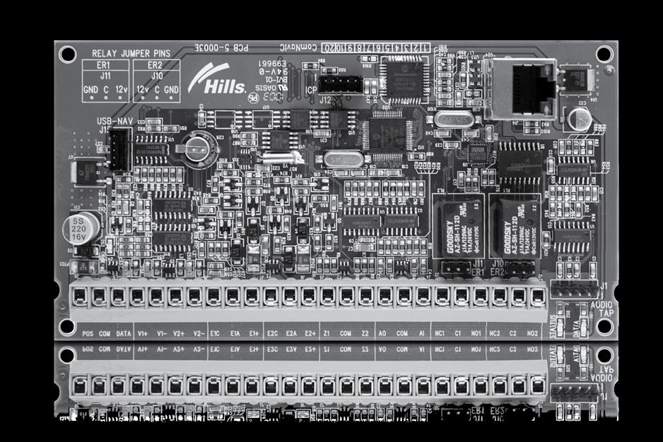
9 Wiring The ComNav Drop all power to the Hills Reliance security system and connect ComNav terminals POS, COMM & DATA to the Hills Reliance bus. A 5-wire interconnecting cable is supplied with the ComNav. Connect one end to J1 (Audio Tap) on the ComNav and the other end to J4 (Audio Tap) on the Reliance board. Important: Ensure the trace is aligned with pin 1 on both taps. Refer Diagrams 4,5,6 & 7 for correct orientation. *Connect J14 (RJ45) to available network port via a patch cable. *Connect E1C, E1A, E1+ in parallel to front door camera 1 *Connect E2C, E2A, E2+ in parallel to front door camera 2 *Connect V1+, V1- and V2+, V2 audio input in parallel with VoiceNav audio lines A and B *Connect Zones as required a. 3.3K Single EOL s b. 3.7K Lower zone EOL s (when zone doubled) c. 6.9K Higher zone EOL s (when zone doubled) *Select relay contact requirements via jumpers J10 and J11. Place link between GND and C for negative switch, and 12V+ and C for positive switch, remove link for dry contact switching. Reconnect power. NOTE: *Only required if particular feature is being utilised Hills Reliance Audio tap connection Diagram 4 R8 Important: Ensure the trace is aligned with pin 1 on both panel and ComNav audio taps** 1 Audio Tap Terminal Strip Diagram 5 1 R12 Audio Tap Terminal Strip Diagram 6 1 Audio Tap R128 PCB Overview Terminal Strip 8
10 PCB Layout Diagram 7 Terminal Descriptions Terminal Description 1 Pos Positive terminal on the Hills Reliance panel Panel 2 Com Common terminal on the Hills Reliance panel Bus 3 Data Data terminal on the Hills Reliance panel 4 V1+ Audio Line A, positive Green / White VoiceNav 5 V1- Audio Line A, negative Green Audio 6 V2+ Lines Audio Line B, positive Orange / White 7 V2- Audio Line B, negative Orange 8 E1C Entrance Common terminal on outdoor station 1 Yellow 9 E1A camera Audio terminal on outdoor station 1 Red 10 E1+ 1 Positive terminal on outdoor station 1 Blue 11 E2C Entrance Common terminal on outdoor station 2 Yellow 12 E2A camera Audio terminal on outdoor station 2 Red 13 E2+ 2 Positive terminal on outdoor station 2 Blue 14 Z1 1 st / 3 rd Zone 3K3 = Single Eol s Additional 15 Com Zones Common (-) return for Zone loop 3K7 = Low zones 16 Z2 2 nd / 4 th Zone 6K9 = High zones 17 AO 18 Com Future Use 19 A1 20 NC1 Normal closed, This relay is controlled 21 C1 ER1 Entry Common from the VoiceNav 22 NO1 Relay 1 Normal open communicating with outdoor station 1 23 NC2 ER2 Normal closed This relay is controlled 24 C2 Entry Relay Common from the VoiceNav 25 NO2 2 Normal open communicating with outdoor station 2 9
11 Wiring Structure Diagram 8 Note: Video Intercom requires independent power source 10
12 Loading Factory Defaults (device 191) The ComNav is automatically set to device number 191, and programming is carried out like all other Hills Reliance modules. The following examples show how to access the programming of the ComNav via a standard code pad or a VoiceNav code pad. The ComNav will require defaulting the first time it is accessed by entering [9][1][0][#] or [9][1][0] [ENTER] depending on the method chosen to enter programming. This will only be required once. Using a VoiceNav Code Pad Step Device Programming, Using VoiceNav code pad Defaulting to factory settings 1. [MENU]-[0] Selects main menu - Option 0, Advanced system configuration Enter your code, touch menu to exit. 2. [?]-[?]-[?]-[?] Enter your 4 or 6 digit Programming code Touch 1 for code pad configuration Touch 2 for panel and device configuration Touch 3 to configure service provider phone number Touch menu to exit. 3. [ 2 ] Selects Panel and Device configuration Select a device number followed by enter Touch menu to go back. 4. [ 1 ][ 9 ][ 1 ] [ENTER] Connects to device 191 (ComNav) Selected device 191 is connected Select a feature number followed by enter Touch menu to go back. 5. [ 9 ][ 1 ][ 0 ] [ENTER] Defaults the device, Note: only required once You are now ready to begin ComNav programming 6. [MENU] Moves back to step 4, select a device number 7. [MENU] Moves back to step 3, Advanced system configuration selection. 8. [MENU] Exits from Advanced system configuration. 11
13 Using a Standard Code Pad Step Device Programming, Using standard code pad Example Defaulting to factory settings 1. [ * ] [ 8 ] Selects Panel and Device programming 2. [?]-[?]-[?]-[?] Enter your 4 or 6 digit Programming code 3. [1][9][1] - [#] Connects to device 191 (ComNav) 4. [9][1][0] - [#] Defaults the device, Note: only required once You are now ready to begin ComNav programming 5. [Exit] Moves back to step 3 6. [Exit] Exits programming Enrolling the ComNav (device 191) The Hills Reliance control panels have the ability to automatically find and store all modules that are connected to the communications bus, such as ConmNav, keypads, zone expanders, wireless receivers, output boards and other modules. This allows for polled supervision of these modules, and if the Hills Reliance panel does not detect an enrolled module, a service condition will be generated. To enrol the ComNav module, enter programming as previously described, upon exiting program mode the Hills Reliance control panel will automatically enrol any additional modules that have been connected to the communications bus, it will also delete modules that have been removed. Enrolling takes about 12 seconds and user codes will not be accepted during this time. 12
14 Accessing the ComNav Via a Touch Tone Phone This section describes how to access the ComNav via an off site touch-tone phone. The ComNav must be on an independent line to the touch-tone phone from which you are trying to connect. The ComNav must be pre-programmed by your security service provider to automatically answer the incoming call once the predetermined number of calls / rings have been reached. When the desired number of calls / rings has been reached the ComNav will grab the phone line and a connection has been established, the following will be announced Note: Feature 2, Dial attempts must be set to the desired number of rings before the ComNav will answer an incoming call to begin a voice session. Feature 1, segment 2, answering machine defeat can also be used to bypass onsite answering machines. An installer code is unrestricted and can access all areas of the ComNav, including menu 0.0 Panel and device configuration After connecting, the ComNav will announce Enter your code for system access, press star to cancel Enter your user / master code / Installer code (default master code is 1234 and default Installer code is 9713), the ComNav will announce the recorded system name (if recorded) and list all accessible main menus, you can now make your selection as required. You are now connected to (system name) Press 1 for system status Press 2 for system control Press 3 for intercom control Press 4 for output control Press 5 for message bank Press 0 for system configuration* Press # to exit * Denotes master code access only The above sequence will be shown through out this manual as [PIN] 13
15 Main Menu Structure 1 System Status 2 System Control 2.1 System Status 2.2 Area Control 2.3 Zone Bypass 2.4 Event History Alarm Memory Event History 3 Intercom Control 3.1 Listen In 3.2 Two way communication 4 Output Control 5 Message Bank 5.1 Record an Exit Message 5.2 Record an Entry Message 0 System Configuration 0.1 User Configuration User Pin User Area User Authority 0.2 Time and Date Time Date 0.3 Area Entry Time 0.4 Area Exit Time 0.5 Phone number configuration Alarm Phone Number One Alarm Phone Number Two Alarm Phone Number Three Divert Phone Number One Divert Phone Number Two Divert Phone Number Three SMS Phone Number One SMS Phone Number Two SMS Phone Number Three Service provider phone number Installer access only 0.6 Voice Message Exit message Entry message User name Zone name Area name Output name Room name System name 0.0 Panel and device configuration Installer access only 14
16 Main Menu - Additional Installer information 4 - Output Control The two onboard relays are defaulted as Door 1 and Door 2 control and are controlled when an intercom session is established between an outdoor station and VoiceNav code pads. Relay trigger events are selectable and can be chosen from a drop down Activation events list from within the web interface. Events can only be selected from within the ComNav web interface. Note: From the activation event drop down list output 1 trigger and output 2 trigger are fixed X10 module commands 0 and 1. When selected, they can be controlled directly from within menu 4-output control when connected to a ComNav. Drop down Event X10 Module Number Output 1 trigger 0 Output 2 trigger 1 Additional relay boards (NX-507) can be added, with a system total of 16. An output from a VoiceNav or ComNav is an X10 command, and these commands can be tied to different relays. Set the relay you wish to control to follow event 56 = follow X10 Command. Then tie the relay to the output by setting the corresponding X10 module number (from the chart below) at the X10 address for the relay. Please refer to your NX-507 installation instructions for further details. Note: NX 508 output boards can also be used Outputs X10 Module Number Outputs X10 Module Number
17 0 - System Configuration 0.1 User Configuration 0.2 Time & Date 0.3 Area Entry Time 0.4 Area Exit Time 0.5 Phone number configuration Alarm phone number One Alarm phone number Two Alarm phone number Three Divert phone number One Divert phone number Two Divert phone number Three SMS phone number One SMS phone number Two SMS phone number Three Service provider phone number 0.6 Voice message recording 0.0 Panel and device configuration Service provider phone number Menu This is the phone number you wish your clients to call for servicing; this number will be announced via your VoiceNav code pads, each arming and disarming cycle whilst a system fault is present. How to: Enter Service provider phone number. Step Example Enter service provider phone numbers 1. [PIN] Call the ComNav via an offsite touch-tone phone to begin the session. 2. Press [0] for system configuration menu Press [5] for phone number configuration Press [0] for service provider phone number 3. Select a new alarm / divert / SMS phone number, followed by # 4. 1 st star. Move back to step 3, phone number selection 2 nd star, moves back to system configuration menu 3 rd star, moves back to main menu 4 th star, disconnects session 16
18 0 - System Configuration 0.1 User Configuration 0.2 Time & Date 0.3 Area Entry Time 0.4 Area Exit Time 0.5 Phone number configuration 0.6 Voice message recording 0.0 Panel and device configuration Panel and device configuration This is the access point to program all other devices that are on the Hills Reliance bus, such as the control panel, radio receivers, output modules etc. How to: Record an Exit message Step Example To record a new eit message, from the Voice message recording menu 1. [PIN] 2. Call the ComNav via an offsite touch-tone phone to begin the session. Press [0] for system configuration menu Press [0] for panel and device configuration 3. Select a device number followed by # Device? Is now connected and you are now ready to begin programming 4. 1 st star, moves back to panel and device configuration 2 nd star, moves back to system configuration menu 3 rd star, moves back to main menu 4 th star, disconnects session The above steps presumes you have exited any feature menus within the device you are connected. 17
19 Accessing the ComNav - Via the Web pages Setup Before you are able to access the ComNav s onboard web server you must first set up the correct network settings. Feature 19 IP Feature Settings Feature 20 IP Gatway Feature 21 ComNav IP Address Feature 22 Subnet Mask Note: Feature 21, 21 and 22 will be automatically assigned if on a DHCP network. Please contact your system administrator for assistance with regard to these required settings. Navigating to the ComNav Enter the IP address of your ComNav into the web browser to access the ComNav Configuration Server, Example as per Diagram 9. Depending on setup, you may also be able to navigate directly to the ComNav by entering ComNav directly into the browsers address window as per Diagram 10. Diagram 9 Diagram 10 Note: SSL or Secure Sockets Layer is a security protocol for communications over networks such as the Internet. If SSL is enabled your URL will begin with https: instead of http: (Diagram 11) You will also receive a warning window There is a problem with this websites security certificate, choose continue to this website to connect to the ComNav. Diagram 11 18

20 Welcome page When successfully connected, the ComNav will serve up the welcome page. To access the main menu enter the required user / installer name and password. By default there is only one Installer name and password. User name: dascomnav Password: 9713 Note: Username is case sensitive 19
21 Main Menu (Web) Accesssed with Installer Code Logout Status and Control Voice Reporting Users Welcome to the ComNav Configuration Server! This page is being served by the ComNav at the address specified. To configure a specific item select from the list to the left. SMS Reporting Call Divert Click a menu on the left to continue Reporting Network Settings Feature List Outputs IP Reporting The screen shot above shows the ComNav s complete menu when accessed via an installer code. Network settings, feature list, outputs and IP reporting will not be presented when accessed via a master code and only Status and control will display if a standard user code is used to access the ComNav. Make your programming selection by clicking on one of the left tabs. Note: The ComNav must either be in program mode, or alternately feature 19, option 6 must be enabled before the ComNav will present network settings, feature list, outputs or IP reporting, even when accessed via an installer code. 20
22 SMS Reporting Logout Status and Control Voice Reporting Users SMS Reporting Call Divert Reporting SMS phone numbers 1, 2 and 3 will receive a SMS message upon the selected event in the associated SMS event window being enabled and activated. Enter the SMS server phone number (Telstra s SMS server number is ) and the mobile numbers that are to receive SMS messages. Individual user names can be reported if entered under the Users tab of this web interface.. To report individual area numbers via SMS, enter the area account number in the corresponding feature number within the Hills Reliance control panel, feature 37 will need to be enabled in a single area system. Area Feature Network Settings Feature List Outputs IP Reporting 21
 is a unique identifier assigned to most network interface cards by the manufacturer for identification.")
23 Network Settings Logout Status and Control Voice Reporting Users SMS Reporting Call Divert Reporting Network Settings Feature List Outputs IP Reporting MAC Address: Media Access Control address (MAC address) is a unique identifier assigned to most network interface cards by the manufacturer for identification. Host Name: Fixed as Comnav DHCP: DHCP or Dynamic Host Configuration Protocol, is a computer network protocol used by devices to obtain configuration information for operation in an Internet Protocol network. This protocol reduces system administration workload, allowing networks to add devices with little or no manual intervention SSL Required: SSL or Secure Sockets Layer, is a security protocl for communications over networks such as the Internet. If SSL is selected your URL will begin with https: instead of http: SSL port is defaulted to port 443, however is selectabel from the SSL pot window further down this window. If SSL is not enabled, ComNav operates on port 80, and is non selectable. Web Updates: When enabled, allows updating of the ComNav Configuration Server's web pages via FTP. Normally disabled. Ping: The ping command is always functional whilst the Comanv is in program mode and is defaulted to NOT operate whilst the ComNav is in the normal run mode. Enable this option to allow 22
24 the ComNav to respond to "ping" commands in normal operation. For security reasons it is recommended this option remain disabled during normal operation. Web Time Updates: The ComNav will check its internal and use the internet to compare it against GMT time. This is done every 15min and will update itself if the variance is greater than 3 minutes. Hills Protocols: This protocol is disabled by default, but is active for the first 5min after power up. Allows devices such as iphones and UHS devices to communicate with the ComNav via Hills protocols. IP Address: An Internet Protocol (IP) address is a numerical label that is assigned to devices participating in a computer network. If DHCP is enabled and supported by your network, the comanv IP address will be automatically assigned, other wise you will be required to enter your unique IP address here. Subnet mask: Allows a network to be divided into subnets, and allows the flow of network traffic between hosts to be segregated based on a network configuration. Applying the subnet mask to an IP address splits the address into two parts, an "extended network address" and a host address. A typical subnet mask is Primary DNS: IP address of the primary DNS server. DNS (Domain Name System) allows dedicated servers on the internet to be assign both an IP address and a corresponding name, called a domain name. Secondary DNS: IP address of the secondary DNS server. DNS (Domain Name System) allows dedicated servers on the internet to be assign both an IP address and a corresponding name, called a domain name. SSL Port: Selectable port configuration, defaulted port is

25 Feature List Logout Status and Control Voice Reporting Users SMS Reporting Call Divert Reporting Network Settings Feature List Outputs IP Reporting Zone-doubling - this feature will allow the two onboard zones to double to four zones. Zone Lower Zone Higher Zone Single EOL 3K3 N/A N/A Zone Doubled EOL s N/A 3K7 6K9 Answering machine defeat - When answering machine defeat is enabled, accessing the ComNav remotely is accomplished by calling the phone number the ComNav is connected to and allowing it to ring once or twice, then hanging up. Wait 10 seconds. Then calling back the ComNav, which will now answer the next incoming call. The second call must be made within 60 seconds of the first call Rings to Answer - The number of rings the ComNav must detect before answering the telephone line when initiating a communication session. A value of 1 15 can be entered. Starting Zone - Used to enter the starting zone number of the additional zones on the ComNav. Data Zones Data Zones Data Zones Data Zones 9 = = = = = = = = = = = = = = = Note: Additional zones are only available on the R128 and R12 panels (also NX12 and NX16). As R12 (and NX12) can only expand to a maximum of 16 zones, you may only enter a Starting Zone of 9. This feature is not available for NX4, NX8 or R8 panels. 24
26 Installer Name Default installer name is dascomnav and is case sensitive. Installer name access will present all tabs. Master user name access will not present the Network settings, Feature list, Outputs or IP reporting tabs. Service Number The system service number will be announced at VoiceNav code pads when a system fault is present. GMT Offset Hours/Minutes Sets local GMT (Greenwich Mean Time). Sydney Victoria Tasmania Queensland South Australia Northern Territory ACT Western Australia New Zealand DST Start / End month Selects the months daylight savings begins and ends for the particular installation region. DST Start / End week Selects which Sunday daylight savings begins and ends for the particular installation region. 25

27 Outputs Logout Status and Control Voice Reporting Users SMS Reporting Call Divert Reporting Network Settings Feature List Outputs IP Reporting The two onboard relays are defaulted as Door 1 and Door 2 control and are controlled when an intercom session is established between an outdoor station and VoiceNav code pads. Relay trigger events are selectable and can be chosen from a drop down Activation events list from within the web interface. Events can only be selected from within the ComNav web interface. Note: From the activation event drop down list output 1 Trigger and output 2 Trigger are fixed X10 module commands 0 and 1. This allows you to send an X10 module command 0 or 1 remotely by using Menu 4-Output Control on the ComNav. 26
28 Drop down Event X10 Module Number Output 1 trigger 0 Output 2 trigger 1 Activation Event Select the required event from the drop down list that will activate the corresponding relay Activation Time Time the relay will be active, options Special Timing Minutes On if output should be timed in minutes; off if timed in seconds Latched On if output should latch; off if output should be timed. Code Reset On if output should stop timing upon code entry; off if output should follow timer. Open Schedule On if output should only activate between the opening and closing time Closing Schedule On if output should only activate between the closing and opening time Invert On if output should be inverted Activation Areas Is used to select the area(s) the event must occur in before the output will activate. Schedule Sets the Opening / Closing hours and minutes (24 hour format) and the days of the week the event must occur in before the output will activate. 27

29 IP Reporting Logout Status and Control Voice Reporting Users SMS Reporting Call Divert Reporting Network Settings Feature List Outputs IP Reporting NOT CURRENTLY SUPPORTED 28
30 Worksheets Feature 1 - ComNav Features Option 1 is used to set the zone-doubling feature. This feature will allow the two onboard zones to double to four zones. Please refer to feature 18 for starting zone number. If this feature is unselected, both onboard zones remain as single end of line zones and require 3K3 resistors. When Zone doubling is enabled Lower zones = 3K7 Higher zones = 6K9 Option 2. Answering machines usually answer calls after a long ring period. This segment is used to set the answering machine defeat feature and enable a connection to the ComNav before the answering machine answers the incoming call. When answering machine defeat is enabled, accessing the ComNav remotely is accomplished by calling the phone number the ComNav is connected to and allowing it to ring once or twice, then hanging up. Wait 10 seconds. Then calling back the ComNav, which will now answer the next incoming call. The second call must be made within 60 seconds of the first call. Segments 2 & 3 are reserved Segment 1 (1) Zone doubling (2) Answering machine defeat (3) Reserved (4) Reserved (5) Reserved (6) Reserved (7) Reserved (8) Reserved Segment 2 Reserved Segment 3 Reserved Feature 2 - Number of Rings Feature 2 contains the number of rings the ComNav must detect before answering the telephone line when initiating a communication session. A value of 1 15 can be entered in this segment. Segment 1 Feature 3 - Dial Attempts Feature 3 is used to enter the number of dial attempts the ComNav will make before ending the communication session. A value from 1 15 may be used, and the default is 6. Segment
31 Feature 4 - Voice Reporting Features Event Selection for all Voice dialing numbers Segment 1 (1) Alarms (2) Alarm Restores (3) Open / Close (alarm system disarmed = Open, alarm system armed = close. (4) Zone Bypass and restores (5) Zone Trouble and restores (6) Power Trouble and restores (AC Failure or Low Battery) (7) Tamper and restores (Zones, Box, Code Pad and Zone Activity Monitor) (8) Test Reports Segment 2 (1) System Trouble and restores (Siren, Phone, Expander, Short Circuit) (2) Failure to Communicate (3) Sensor Lost or Sensor Low Battery (4) Program mode, Download and Log Full (full log must be enabled in system options) (5) Cancel Code (cancel reporting must be enabled in area options) (6) Recent Closing, Exit Error (7) Reserved (8) Reserved Feature 5 - Alarm Phone Number One (1) The first voice message phone number is programmed in feature 5 15 = Pulse dialing in the segment where pulse dialing should begin 14 = Indicates the end of the phone number 13 = Creates a four second delay 12 = # 11 = * Segments Feature 6 - Alarm Phone Number Two (2) The second voice message phone number is programmed in feature 5 15 = Pulse dialing in the segment where pulse dialing should begin 14 = Indicates the end of the phone number 13 = Creates a four second delay 12 = # 11 = * Segments
32 Feature 7 - Alarm Phone Number Three (3) The third voice message phone number is programmed in feature 5 15 = Pulse dialing in the segment where pulse dialing should begin 14 = Indicates the end of the phone number 13 = Creates a four second delay 12 = # 11 = * Segments Note: If multiple phone numbers are entered, the ComNav will call each number in turn until it is answered or the designated number of dial attempts set in Feature 3 has been reached. The ComNav will first call phone number 1, wait 25 seconds for a PIN to be entered, if not entered it will hang up for 6 seconds, then call phone number 2 and repeats this process for phone number 3. Feature 8 - SMS server number The in-dial number of the SMS server (125107) Segments Feature 9 - SMS Phone Number One (1) The first SMS phone number is programmed in feature 9 15 = Pulse dialing in the segment where pulse dialing should begin 14 = Indicates the end of the phone number 13 = Creates a four second delay 12 = # 11 = * Segments Feature 10 - SMS Event Select for SMS phone number One (1) Event selection for SMS phone number 1 Segment 1 (1) Alarms (2) Alarm Restores (3) Open / Close (alarm system disarmed = Open, alarm system armed = close. (4) Zone Bypass and restores (5) Zone Trouble and restores (6) Power Trouble and restores (AC Failure or Low Battery) (7) Tamper and restores (Zones, Box, Code Pad and Zone Activity Monitor) (8) Test Reports Segment 2 (1) System Trouble and restores (Siren, Phone, Expander, Short Circuit) 31
33 (2) Failure to Communicate (3) Sensor Lost or Sensor Low Battery (4) Program mode, Download and Log Full (full log must be enabled in system options) (5) Cancel Code (cancel reporting must be enabled in area options) (6) Recent Closing, Exit Error (7) Reserved (8) Reserved Feature 11 - SMS Phone Number Two (2) The second SMS phone number is programmed in feature = Pulse dialing in the segment where pulse dialing should begin 14 = Indicates the end of the phone number 13 = Creates a four second delay 12 = # 11 = * Segments Feature 12 - SMS Event Select for SMS phone number Two (2) Event selection for SMS phone number 2 Segment 1 (1) Alarms (2) Alarm Restores (3) Open / Close (alarm system disarmed = Open, alarm system armed = close. (4) Zone Bypass and restores (5) Zone Trouble and restores (6) Power Trouble and restores (AC Failure or Low Battery) (7) Tamper and restores (Zones, Box, Code Pad and Zone Activity Monitor) (8) Test Reports Segment 2 (1) System Trouble and restores (Siren, Phone, Expander, Short Circuit) (2) Failure to Communicate (3) Sensor Lost or Sensor Low Battery (4) Program mode, Download and Log Full (full log must be enabled in system options) (5) Cancel Code (cancel reporting must be enabled in area options) (6) Recent Closing, Exit Error (7) Reserved (8) Reserved 32
34 Feature 13 - SMS Phone Number Three(3) The third SMS phone number is programmed in feature = Pulse dialing in the segment where pulse dialing should begin 14 = Indicates the end of the phone number 13 = Creates a four second delay 12 = # 11 = * Segments Feature 14 - SMS Event Select for SMS phone number Three (3) Event selection for SMS phone number 3 Segment 1 (1) Alarms (2) Alarm Restores (3) Open / Close (alarm system disarmed = Open, alarm system armed = close. (4) Zone Bypass and restores (5) Zone Trouble and restores (6) Power Trouble and restores (AC Failure or Low Battery) (7) Tamper and restores (Zones, Box, Code Pad and Zone Activity Monitor) (8) Test Reports Segment 2 (1) System Trouble and restores (Siren, Phone, Expander, Short Circuit) (2) Failure to Communicate (3) Sensor Lost or Sensor Low Battery (4) Program mode, Download and Log Full (full log must be enabled in system options) (5) Cancel Code (cancel reporting must be enabled in area options) (6) Recent Closing, Exit Error (7) Reserved (8) Reserved 33
35 Feature 15 - Divert Phone Number One (1) The first Divert phone number is programmed in feature 15 A call divert phone numbers will be dialed when a call is initiated from an outdoor station. The outdoor station must be interfaced with the Hills Reliance security system via the ComNav. The Hills Reliance security system must also be in the armed condition 15 = Pulse dialing in the segment where pulse dialing should begin 14 = Indicates the end of the phone number 13 = Creates a four second delay 12 = # 11 = * Segments Feature 16 - Divert Phone Number Two (2) The second Divert phone number is programmed in feature 16 A call divert phone numbers will be dialed when a call is initiated from an outdoor station. The outdoor station must be interfaced with the Hills Reliance security system via the ComNav. The Hills Reliance security system must also be in the armed condition 15 = Pulse dialing in the segment where pulse dialing should begin 14 = Indicates the end of the phone number 13 = Creates a four second delay 12 = # 11 = * Segments Feature 17 - Divert Phone Number Three (3) The third Divert phone number is programmed in feature 17 A call divert phone numbers will be dialed when a call is initiated from an outdoor station. The outdoor station must be interfaced with the Hills Reliance security system via the ComNav. The Hills Reliance security system must also be in the armed condition 15 = Pulse dialing in the segment where pulse dialing should begin 14 = Indicates the end of the phone number 13 = Creates a four second delay 12 = # 11 = * Segments
36 Feature 18 - Zone Starting Number Feature 18 is used to enter the starting zone number of the additional zones on the ComNav. The two zones can also be zone doubled, please refer to feature 1 to enable the zone doubling feature. Data Zones Data Zones Data Zones Data Zones 9 = = = = = = = = = = = = = = = Note: Additional zones are only available on the R128 and R12 panels (also NX12 and NX16). As R12 (and NX12) can only expand to a maximum of 16 zones, only option 9 is available (zones 9 12) This feature is not available for NX4, NX8 or R8 panels. Segment 1 35
37 Feature 19 - IP Feature Options Feature 19 is used to set required network settings. Enable DHCP: DHCP or Dynamic Host Configuration Protocol, is a computer network protocol used by devices to obtain configuration information for operation in an Internet Protocol network. This protocol reduces system administration workload, allowing networks to add devices with little or no manual intervention. Enable SSL: or Secure Sockets Layer, is a security protocl for communications over networks such as the Internet. If SSL is selected your URL will begin with https: instead of http: SSL port is defaulted to port 443, however is selectabel from the SSL pot window from within the web interface. If SSL is not enabled, ComNav operates on port 80, and is non selectable. Enable Ping in the run mode: The ping command is always functional whilst the Comanv is in program mode and is defaulted to NOT operate whilst the ComNav is in the normal run mode. Enable this option to allow the ComNav to respond to "ping" commands in normal operation. For security reasons it is recommended this option remain disabled during normal operation. Enable Web page updates without a login: When enabled, allows updating of the ComNav Configuration Server's web pages via FTP. Normally disabled. Enable periodic update of clock via internet: The ComNav will check its internal and use the internet to compare it against GMT time. This is done every 15min and will update itself if the variance is greater than 3 minutes. Enable Web programming: When enabled, access to Network settings, Feature list, Outputs and IP reporting via the ComNavs web pages is granted, other wise the ComNav will need to be in program mode to access these additional featurers. Enable Hills protocol server: This protocol is disabled by default, but is active for the first 5min after power up. Allows devices such as iphones and UHS devices to communicate with the ComNav via Hills protocols. Segment 1 (1) Enable DHCP (2) Enable SSL 3 Enable Web page updates without a login 4 Enable Ping in run mode 5 Enable periodic update of clock via internet Enable Web programming of Network settings, Feature list, Outputs 6 and IP reporting without ComNav needing to be in program mode 7 Enable Hills protocol server 8 Reserved Segment 2 Reserved 36
38 Feature 20 - IP Gateway The 4 segments in feature 20 are used to set the IP address of the networks gateway. In homes, the gateway is usually the Intermet Service Provider (ISP) device that connects the user to the internet, such as a DSL or cable modem. In an enterprise system, the gateway is the node that routes the traffic from a workstation to another network segment. The default gateway is commonly the node connecting the internal networks and the outside network (Internet). Segments 1-4 Feature 21 - ComNav IP Address The 4 segments in feature 21 are used to set the IP address of the ComNav so as it can be identified on the network. Segments 1-4 Feature 22 - Subnet Mask The 4 segments in feature 22 are used to set the Subnet mask. Segments 1-4 Feature 23 - DNS Server 1 The 4 segments in feature 23 are used to set the networks DNS server address. Segments 1-4 Feature 24 - DNS Server 2 The 4 segments in feature 24 are used to set the networks DNS server address. Segments
39 Feature 25 - UHS Client server IP address The 4 segments in feature 21 are used to set the IP address of the ComNav so as it can be identified on the network by the UHS ultra agent. Segments 1-4 Feature 26 - UHS Client reporting selections Event selection for UHS client reporting Segment 1 (1) Alarms (2) Alarm Restores (3) Open / Close (alarm system disarmed = Open, alarm system armed = close. (4) Zone Bypass and restores (5) Zone Trouble and restores (6) Power Trouble and restores (AC Failure or Low Battery) (7) Tamper and restores (Zones, Box, Code Pad and Zone Activity Monitor) (8) Test Reports Segment 2 (1) System Trouble and restores (Siren, Phone, Expander, Short Circuit) (2) Failure to Communicate (3) Sensor Lost or Sensor Low Battery (4) Program mode, Download and Log Full (full log must be enabled in system options) (5) Cancel Code (cancel reporting must be enabled in area options) (6) Recent Closing, Exit Error (7) Reserved (8) Reserved 38
40 System Status Messages Table Zone Number / Zone Name In Alarm This zone has triggered a system alarm condition Is bypassed This zone is isolated (disabled) and will not activate an alarm Chime is set This zone is part of the chime group Is not secure This zone is not closed Fire alarm This zone has triggered a fire alarm Tamper This zone has triggered a tamper alarm Trouble fault This zone has an open circuit Loss of wireless supervision This zone is a wireless device and has lost its communication link with the control panel Low battery This zone is a wireless device and needs its battery changed Area Number / Area Name Is On in the away mode This area is armed in the away mode Is On in the stay mode This area is armed in the stay mode Is ready This area is secure and ready to be armed Is not ready This area is NOT ready to be armed, a zone is not secure All areas are on in the away mode All areas in this multi partition system are armed in the away mode All areas are on in the stay mode All areas in this multi partition system are armed in the stay mode All areas are ready All areas in this multi partition system are secure and ready to be armed System AC power fail The security system has lost its electricity power Low battery The security systems back up battery requires charging Battery test fail The security systems back up battery requires changing Box tamper The security systems cabinet tamper input has activated Siren trouble The security systems external siren has a problem Over current The security system is drawing too much current Time and date loss The security system time and date need resetting Communication fault The security system has detected a problem with the phone line Expander Low battery A remote power supply s back up battery requires charging AC power fail A remote power supply has lost its electricity power Box tamper An expanders cabinet tamper input has activated 39
41 Code Pad Fire alarm A fire alarm has been activated at the code pad Panic A panic alarm has been activated at the code pad Medical A medical alarm has been activated at the code pad 40
Table of Contents. Phone number configuration...15 Alarm Phone numbers, 1, 2 & Divert phone numbers 1, 2 &
 Table of Contents Introduction... 4 Warning... 5 Warranty... 5 Glossary of terms... 6 Legend... 7 Feature & Benefits... 8 1. Phone Line connection... 8 Phone Line connection, and network connection...9
ComNav Installation Manual
 ComNav Installation Manual USB-NAV ICP J12 J11 J10 ER1 ER2 POS COM DATA V1+ V1- V2+ V2- E1C E1A E1+ E2C E2A E2+ Z1 COM Z2 AO COM AI NC1 C1 N01 NC2 C2 N02 AUDIO TAP Contents Getting Started 2 Overview 2
NX-595E User Manual P/N REV C ISS 02JUL14. Downloaded from manuals search engine
 NX-595E User Manual P/N 230243 REV C ISS 02JUL14 Copyright Trademarks and patents Manufacturer Compliance EU directives Contact information Customer support 2014 UTC Fire & Security Americas Corporation,
VoiceNav User Manual
 r VoiceNav User Manual 1 Table of contents Introduction 2 Drawing 3 Glossary of terms 4 Glossary of terms continued 5 Legend 5 Warranty 5 Indicators, icons and lights 6 Away arming 7 Stay arming 8 Disarming
Installation Manual GENERAL DESCRIPTION...2 WIRING INFORMATION FOR NX-507 AND NX NX-507 TERMINAL DESCRIPTION...3 NX-507 DRAWING...
 NX-0 RELAY EXPANDER NX-0 OUTPUT EXPANDER Installation Manual GENERAL DESCRIPTION... WIRING INFORMATION FOR NX-0 AND NX-0... NX-0 TERMINAL DESCRIPTION... NX-0 DRAWING... NX-0 TERMINAL DESCRIPTION... NX-0
NetworX Series. NX-507E RELAY EXPANDER NX-508E OUTPUT EXPANDER Installation and Startup
 NetworX Series NX-0E RELAY EXPANDER NX-0E OUTPUT EXPANDER Installation and Startup NX-0E / NX-0E AUXILIARY MODULES TABLE OF CONTENTS I. GENERAL DESCRIPTION... II. WIRING INFORMATION... III. NX-0E TERMINAL
NetworX Series. NX-507E RELAY EXPANDER NX-508E OUTPUT EXPANDER Installation and Startup
 NetworX Series NX-0E RELAY EXPANDER NX-0E OUTPUT EXPANDER Installation and Startup NX-0E / NX-0E AUXILIARY MODULES TABLE OF CONTENTS I. GENERAL DESCRIPTION... II. WIRING INFORMATION... III. NX-0E TERMINAL
VISTA 12a / 48a TECHNICAL TRAINING. The Best in Security plus Everyday Convenience & Control
 VISTA 12a / 48a TECHNICAL TRAINING The Best in Security plus Everyday Convenience & Control Version #.007 7th June 2005 VISTA 12a / 48a Training Guide Index 1. Vista Family Features....... p. 3 2. Wiring
EC-11 Ethernet Converter
 EC-11 Ethernet Converter PSTN Contact ID to TCP Converter Installation and Operations Manual Version 8.H3.MID 1 Table of Contents About EC-11 Ethernet Converter... 3 Circuit Board Layout and Wiring Diagram...
2-Wire Residential Intercom
 www.vip-vision.com 2-Wire Residential Intercom QUICK INSTALLATION GUIDE v1.3 1 Table of Contents 1. Components...3 2. Installation...7 a) 1 Indoor Monitor to 1 Door Station (No Network Functionality)...8
WELCOME. For customer support or any inquiries, please visit our web site at or contact us at
 WELCOME Congratulations on purchasing the GBF Smart Four Wire Intercom System. Our factory engineers were the first to enable multiple security cameras being monitored through a smart mobile device and
Avantis AXI WEB SERVER MODULE USER MANUAL
 Avantis AXI WEB SERVER MODULE USER MANUAL CONTENTS CHAPTER 1: SYSTEM LOGIN AND WEB PAGE LAYOUT 1.0 ACCESSING THE WEB PAGE 1.1 USER AUTHORITY 1.1.1 MASTER USER 1.1.2 USER/ GUEST SETTING 1.1.3 INSTALLER
Zartek. CDP-808 Two Button Wireless Intercom Installers Manual
 Zartek CDP-808 Two Button Wireless Intercom Installers Manual ZA-614 Two Button Gate station including power supply, relay board and external antenna ZA-613 Handsets with charger ZA-613-E Handsets with
4XLFN6WDUW*XLGH. LYNXR is not intended for UL985 Household Fire applications.
 K5484 7/00 /
2 IDS LCD Keypad User Manual C Issued March 2009
 2 3 4 Contents 1. Introduction to the IDS LCD Digital Keypad...8 2. Arming the Control Panel...8 2.1 Away Arming...8 2.1.1 How to Away Arm...8 2.1.2 Quick Away Arm Shortcut Key...8 2.2 Stay Arming...9
DAS 250L CONTROL COMMUNICATOR INSTALLATION MANUAL
 DAS 250L CONTROL COMMUNICATOR INSTALLATION MANUAL TABLE OF CONTENTS 1. GENERAL DESCRIPTION... P.2 2. STANDARD AND OPTIONAL PARTS LIST..... P.2 3. FEATURE DEFINITIONS... P.3 4. TERMINAL DRAWING AND SPECIAL
Steady green On hook. Slow flashing green Off hook. Off Port not ready. Off No link. Fast flashing green Upgrading firmware.
 Product Features Product Features Top Panel Feature Description Steady green On hook. Phone Phone 2 Slow flashing green Off hook. Off Port not ready. Flashing green Transmitting or receiving data through
IDS. Users Guide to Keypad Functions S E C U R I T Y MANUAL NO D ISSUED NOVEMBER 2002 VERSION 2.
 INHEP DIGITAL IDS S E C U R I T Y Users Guide to Keypad Functions MANUAL NO. 700-146-01D ISSUED NOVEMBER 2002 VERSION 2.17 Summary of Operation A rm/ disarm [#] + [USER CODE] Quick Quick Quick Away Arm
_A_en_LED63VG VOICE GUIDE KEYPAD LED63VG
 18020502_A_en_LED6VG VOICE GUIDE KEYPAD LED6VG Disclaimer While every effort has been made to ensure that the information in this manual is accurate and complete, no liability can be accepted for any errors
DOLXFD1000B. Waterproof Access Control/Reader
 DOLXFD1000B Waterproof Access Control/Reader INTRODUCTION The DOLXFD1000B is a single- entry multi-function Access Controller with integrated keypad and card reader. It is designed and manufactured to
Modules Programming Guide. paradox.com
 Keypad Modules Annunciator Module Motion Detector Modules Zone Expansion Modules Access Control Module Voice Assisted Modules Accessory Modules Integration Module Internet Module Modules Programming Guide
Quick Start Guide. Cisco SPA232D Mobility Enhanced ATA
 Quick Start Guide Cisco SPA232D Mobility Enhanced ATA Package Contents Analog Telephone Adapter Ethernet Cable Phone Cable Power Adapter Quick Start Guide Product CD-ROM Welcome Thank you for choosing
RANGER 9000E DOWNLOADABLE CONTROL COMMUNICATOR INSTALLATION MANUAL
 RANGER 9000E DOWNLOADABLE CONTROL COMMUNICATOR INSTALLATION MANUAL TABLE OF CONTENTS GENERAL DESCRIPTION... 2 STANDARD AND OPTIONAL PARTS LIST... 2 FEATURE DEFINITIONS... 3 TERMINAL DRAWING AND SPECIAL
Installing Sentor. Hardware Installation
 Remote base site monitoring and control Installing Sentor Hardware Installation Copyright 2000 Sentor Monitoring Systems Pty Ltd Contents: 1 Introduction... 1 2 Sentor GUI... 2 3 ST3000 Controller... 3
1HWZRU;1;( Table of Contents. General Description...2. Ordering Information...2. Feature Definitions...3. Programming the LED Keypads...
 HWZRU;;( Control/Communicator Installation Manual Table of Contents General Description... Ordering Information... Feature Definitions... Programming the LED Keypads... Programming the NX-E...9 Types of
EN Series / EXN. Telephone Entry & Access Control System. Quick Start Guide (EN-2A4) ( EXN )
 ( EXN )") EN Series / EXN Telephone Entry & Access Control System (EN-2A4) ( EXN ) Quick Start Guide (P/N: EN-2A4 / EN-2M4, EN-2A7 / EN-2M7, EN-2A10 / EN-2M10, and EXN) NOTE: This Quick start guide is applicable
EN Series / EXN Telephone Entry & Access Control System (EN-2A4) ( EXN ) Quick Start Guide (P/N: EN-2A4 / EN-2M4, EN-2A7 / EN-2M7, EN-2A10 / EN-2M10, and EXN) NOTE: This Quick start guide is applicable
Indoor/Outdoor Proximity Reader and Keypad with 10cm (4in) Read Range
 Read Range") Indoor/Outdoor Proximity Reader and Keypad with 10cm (4in) Read Range Stand alone CR-R885-SB Installation and Operating Instructions V1.1 TABLE OF CONTENTS Installation... 2 Mounting and Wiring... 2 Mounting
Indoor/Outdoor Proximity Reader and Keypad with 10cm (4in) Read Range Stand alone CR-R885-SB Installation and Operating Instructions V1.1 TABLE OF CONTENTS Installation... 2 Mounting and Wiring... 2 Mounting
660/960 Installation Guide
 660/960 Installation Guide Compatible Equipment 660: Any Scantronic control panel. 960: All control panels with the Scantronic plug-on footprint pins. 496354 Issue 1 1 of 16 660/960 Introduction The 660/960
IDS X-Series User Manual E Issued June 2013
 1 2 Contents 1. Introduction to the IDS X-Series Panels... 6 2. Before Operating Your Alarm System... 6 3. Understanding the Keypad LEDs... 7 3.1 Viewing Data on an LED Keypad... 11 3.2 Entering Data on
SOFTWARE VERSION 3.20
 48EPEP-00 SOFTWARE VERSION 3.20 HEXA PROGRAMMING: Addresses 000 to 043 and 300 to 527 are programmed using the Hexa Programming method. In this mode, you can enter any hexa-digit from 0-F where keys [1]
NETWORK SETUP. 1. From the IP-Modules Home page Click Login
 R4816-IP MODULE FOR RUNNER 1. Connect the IP-Module to your Computers LAN port with the supplied Patch cable. 2. Connect power to the IP-Module, this can come from the Alarm Panel or even a 12V battery.
DAS ALPHA NUMERIC LCD CODEPAD INSTALLATION MANUAL
 DAS ALPHA NUMERIC LCD CODEPAD INSTALLATION MANUAL TABLE OF CONTENTS General Description... P.2 Power Up Information... P.3 Entering The Program Mode... P.4 Selecting Panel Type... P.4 Programming Defaults...
Series. NX-8-EUR Control Panel. Installation manual
 g GE Security NetworX TM Series NX-8-EUR Control Panel Installation manual NX-8-EUR Installation manual Page 2 23/12/04 CONTENTS CONTENTS...3 GENERAL INFORMATION...5 ORDERING INFORMATION...5 FEATURE DEFINITIONS...6
Welcome Contents Diagram
 Welcome Congratulations on your purchase of our GBF PL960 Series of IP Doorbells. Our factory engineers were the first to enable viewing of multiple security cameras through your handheld smart device,
AUDIO AND VIDEO DOOR ENTRY SYSTEM WITH NEXA CODED PANEL
 AUDIO AND VIDEO DOOR ENTRY SYSTEM WITH NEXA CODED PANEL 2 INTRODUCTION First and foremost we would like to thank you for purchasing this product. Our commitment to satisfying our customers can be seen
* * ARM MONITOR EXCLUDE MEMORY. HomeSafe Security Panel 5400/16CB. Programming Manual C-Bus Supplement
 * * ARM 1 2 3 MONITOR 4 5 6 EXCLUDE 7 8 9 MEMORY P 0 E HomeSafe Security Panel 5400/16CB Programming Manual C-Bus Supplement Contents 1.0 Product Range...3 2.0 Features...3 2.1 Control Panel Features...3
USERS MANUAL.
 USERS MANUAL Ness Corporation Pty Ltd ABN 28 069 984 372 Private Bag 23 Seven Hills NSW 1730 Australia Ph +61 2 8825 9222 Fax +61 2 9838 8508 Email: ness@ness.com.au SYDNEY Ph 02 8825 9222 Fax 02 9674
Applicable to the EURO 46, 76, 162 and 280 control panels, software V9 or above.
 Applicable to the EURO 46, 76, 162 and 280 control panels, software V9 or above. Please note that this manual has been prepared to highlight the new PD6662, BS8243 and EN50131-1 features. RINS1530-1 CHAPTER
Access control panel U-Prox IC E (Elevator control)
") 1.003 Access control panel U-Prox IC E (Elevator control) Installation and programming manual About this document http://u-prox.com This manual covers installation, adjustment and use of U-Prox IC E (hereinafter
1.003 Access control panel U-Prox IC E (Elevator control) Installation and programming manual About this document http://u-prox.com This manual covers installation, adjustment and use of U-Prox IC E (hereinafter
Ademco Vista-20SE/First Alert FA-162C Program Sheet
 Enter Program 1. 4112 + 8 + 0 + 0 (Display should show 20) or Power down then back up and press * and # within 1 minute (If exiting programming you can re-enter within 1 minute by pressing * and #) Exit
Safecom Solution-16 Quick Reference Guide ISSUE 1.10
 Safecom Solution-16 Quick Reference Guide ISSUE 1.10 2 Solution-16 Safecom Quick Reference Guide Safecom Solution-16 Quick Reference Guide Copyright 1998 by, SYDNEY, AUSTRALIA Document Part Number MA8016Q
Installation Manual Premier Elite ComIP
 Installation Manual Premier Elite ComIP INS273-6 Product Type - CEJ0000 1. Overview Introduction The ComIP module allows the Premier & Premier Elite control panels to be connected to either a Local Area
Wireless Alarm System User Guide
 Wireless Alarm System User Guide Alarm Panel Time 10:09 c RINS1902 Document SAP: 102015108-03 Contents ProControl+ 4 Setting Devices 5 The Wireless Panel Keypad 5 Wireless Keyfobs 5 Locking the Keyfob
SOFTWARE VERSION 3.10
 738PEP-03 SOFTWARE VERSION 3.10 HEXA PROGRAMMING: Addresses 000 to 043 and 300 to 527 are programmed using the Hexa Programming method. In this mode, you can enter any hexa-digit from 0-F where keys [1]
Wireless Doorphone Intercom
 Security Made Smarter Wireless Doorphone Intercom EN INSTRUCTION MANUAL DOORBELL OVERVIEW MICROPHONE LEDS CAMERA LENS LIGHT SENSOR Detects ambient light and turns on the LEDS to provide clear color night
INT-TSI Brief User Manual
 int-tsi_u_en 03/15 Keypad INT-TSI Brief User Manual SATEL sp. z o.o. ul. Budowlanych 66 80-298 Gdańsk POLAND tel. 58 320 94 00 info@satel.pl www.satel.eu Firmware version 1.04 WARNINGS Please read this
Ethernet communication module ETHM-1 Plus
 Ethernet communication module ETHM-1 Plus Firmware version 2.05 ethm1_plus_en 07/18 SATEL sp. z o.o. ul. Budowlanych 66 80-298 Gdańsk POLAND tel. + 48 58 320 94 00 www.satel.eu IMPORTANT The module should
NX-148 LCD KEYPAD INSTALLATION MANUAL
 NX-148 LCD KEYPAD INSTALLATION MANUAL Table of Contents Entering the Program Mode... 2 Selecting the Module to Program... 2 Programming a Location... 2 NX-148 Library... 3 Loading Factory Defaults... 3
CA-A480-A Elevator Controller. Reference & Installation Manual
 CA-A480-A Elevator Controller Reference & Installation Manual TABLE OF CONTENTS INTRODUCTION.................................................................. 4 Introduction.............................................................................................
THE OPERATOR INTRODUCTION 2 ACCESSING YOUR SYSTEM 2 FUNCTIONS OF THE "OPERATOR" 3 PROGRAMMING/CHANGING ACCESS CODES 12 ACTIVATING EMERGENCY ALARMS 13
 THE OPERATOR INTRODUCTION 2 ACCESSING YOUR SYSTEM 2 FUNCTIONS OF THE "OPERATOR" 3 SECTION I. CHECKING SYSTEM STATUS 3 SECTION II. USING THE MENU 4 SECTION III. ARMING YOUR SECURITY SYSTEM 5 SECTION IV.
AC-115 Compact Networked Single-Door Controller Hardware Installation and Programming
 AC-115 Compact Networked Single- Controller Hardware Installation and Programming Copyright 2013 by Rosslare. All rights reserved. This manual and the information contained herein are proprietary to REL,
Wireless Key fob, Key pad & Receiver Range
 Wireless Key fob, Key pad & Receiver Range 4Ch Wireless Receiver 4x Voltage Free relay outputs (NO + NC) 100m Transmission range Multiple user codes 2 Channel wireless control Clear hinge up lid 12V DC
High Security and Access System EVO48 V2.1 EVO192 V2.1
 High Security and Access System EVO48 V2.1 EVO192 V2.1 Programming Guide Includes LCD Keypad Programming We hope this product performs to your complete satisfaction. Should you have any questions or comments,
Model HM-535 Power Supply Installation and Service Instructions
 Model HM-535 Power Supply Installation and Service Instructions 430-535 0104 2004 Heritage MedCall, Inc SENTRY INSTALLATION & SERVICE INSTRUCTIONS POWER SUPPLY UNIT Model HM-535 IMPORTANT SAFETY INSTRUCTIONS
CP150B Vandal & Weather Resistant Keypad Security Systems
 Vandal & Weather Resistant Keypad Security Systems EN Security System CP150B - Vandal & Weather Resistant Keypad The CP150B keypad provides alarm and or access control functionality when used on selected
: DOOR ENTRY UNIT USER MANUAL EIS-R. Programming Software. v
 : DOOR ENTRY UNIT EIS-R Programming Software v.1.4.20161115 Contents 1 FOR YOUR SAFETY...3 2 INTRODUCTION...4 3 EIS-R FEATURES and APPLICATIONS...5 4 START UP...6 5 LED INDICATION...7 6 CONNECTION DIAGRAM...8
Important Notice. Customer Information. 2 WisDom User Manual
 User Manual Important Notice This manual is delivered subject to the following conditions and restrictions: This manual contains proprietary information belonging to RISCO Group. The information is supplied
e-ask electronic Access Security Keyless-entry OEM / Dealer / Installer Cargo Lock / Unlock Version Installation & Instructions (UM04 ~ )
") e-ask electronic Access Security Keyless-entry OEM / Dealer / Installer Cargo Lock / Unlock Version Installation & Instructions (UM04 ~ 18990-04) Table of Contents Introduction... 1 e-fob Operation and
e-ask electronic Access Security Keyless-entry OEM / Dealer / Installer Cargo Lock / Unlock Version Installation & Instructions (UM04 ~ 18990-04) Table of Contents Introduction... 1 e-fob Operation and
Control Panel Solution 2000 / 3000
 Control Panel Solution 2000 / 3000 en Quick Reference Guide Control Panel Table of contents en 3 Table of contents 1 Introduction 6 2 Programming 7 2.1 Alphanumeric Codepad Menu Programming 7 2.2 ICON
GV-Card Reader. User s Manual
 GV-Card Reader User s Manual Before attempting to connect or operate this product, please read these instructions carefully and save this manual for future use. READER-B 2016 GeoVision, Inc. All rights
NISTA DEVICES GmbH 2013 All Rights Reserved. Door Access Control with the VoIP interface IP epcr Release 1.02
 NISTA DEICES GmbH 2013 All Rights Reserved Door Access Control with the oip interface IP 39-60 epcr Release 1.02 1 NISTA DEICES GmbH 2013 All Rights Reserved IP Door Phones IP 39-60ePCR Quick Installation
Quick Start Guide. Cisco SPA100 Series Analog Telephone Adapters. SPA112 Two Port Phone Adapter SPA122 ATA with Router
 Quick Start Guide Cisco SPA100 Series Analog Telephone Adapters SPA112 Two Port Phone Adapter SPA122 ATA with Router Package Contents Analog Telephone Adapter Ethernet Cable Power Adapter Quick Start Guide
Installer Notes 4110DL/XM, Vista 10, Vista-20, Via-30PSE
 Installer Notes 4110DL/XM, Vista 10, Vista-20, Via-30PSE 1. Programming can only be done with a 6139 Alpha Keypad on Vista-10/20/30PSE models. 2. When entering programming for the first time during Installations
Property of Monitronics Inc
 Enter Program 1. 4112 + 8 + 0 + 0 (Display should show 20) or Power down then back up and press * and # within 1 minute (If exiting programming you can re-enter within 1 minute by pressing * and #) Exit
XT30/XT50 PROGRAMMING PART 1. Slide 1. Slide 2. Slide 3. Objectives. XT30/XT50 Basic Training Programming- Part 1. Accessing the Programmer
 Slide 1 XT30/XT50 Basic Training Programming- Part 1 Slide 2 Objectives After completing this course you will: 1) Understand how to prepare the panel for programming and how to access the built-in programmer.
Contents. 4. Disarming the Control Panel How to Disarm with a User Code How to Disarm using a Key-Switch or Remote...
 Contents 1. Introduction to the Watchguard WGAP864 LCD Digital Keypad... 6 2. Viewing Violated Zones... 6 3. Arming the Control Panel... 7 3.1 Away Arming... 7 3.1.1 How to Away Arm... 7 3.1.2 Quick Away
Property of Monitronics Inc
 Enter Program (Locations 034 to 410) 1. Press Program Button on main panel 2. At keypad press 9 + Program Code (9 8 7 6 5) or 1. Power down with black switch on bottom left of panel 2. Power up while holding
epad 5.0 Mobile Keypad
 Programming Guide epad 5.0 Mobile Keypad Description Providing much-needed flexibility, the epad 5.0 Mobile Keypad allows users to control their DMP security system using an Internet browser. The epad
CyberData SIP Intercom Integration with 8x8
 CyberData SIP Intercom Integration with 8x8 This document covers the integration of CyberData s SIP Intercom with 8x8. This document was written for 8x8 and the following CyberData Products: 011214 SIP
LCD62. Keypad. User Manual
 LCD62 Keypad User Manual Disclaimer: While every effort has been made to ensure that the information in this manual is accurate and complete, no liability can be accepted for any errors or omissions The
Installation Manual & User Instructions. MultiCom 500
 Installation Manual & User Instructions For MultiCom 500 Multi resident GSM Intercom System Contents Section Description Page 1 Introduction 3 2 Getting started 3 3 SIM card 3 4 Wiring 4 5 Keypad / onscreen
Agility 2-Way Wireless Slim Keypad
 Agility 2-Way Wireless Slim Keypad Models: : RW132KL1, RW132KL1P Instruction Manual Agility 2-Way Wireless Slim Outdoor Keypad Table of Contents INTRODUCTION 3 MAIN FEATURES 3 COMMUNICATION SETUP 3 MOUNTING
NetworX Series NX-8V2 Control Panel Installation and Startup
 NetworX Series NX-V Control Panel Installation and Startup 00 GE Security All rights reserved. These instructions do not purport to cover all details or variations in equipment nor to provide every possible
: DOOR ENTRY UNIT USER MANUAL. Programming Software. v
 : DOOR ENTRY UNIT Programming Software MODELS: EIS-1, EIS-2 OR EIS-4 v.1.4.20161115 Contents 1 FOR YOUR SAFETY...3 2 INTRODUCTION...4 3 EIS-1, EIS-2, EIS-4 FEATURES and APPLICATIONS...5 4 START UP...6
: DOOR ENTRY UNIT USER MANUAL EIS-LCD. Programming Software
 : DOOR ENTRY UNIT EIS-LCD Programming Software v.2.0 2018 Page 1 Contents 1 FOR YOUR SAFETY...5 2 INTRODUCTION...6 3 EIS-LCD, EIS-40 FEATURES AND APPLICATIONS...7 4 START UP...8 5 LED INDICATION...9 6
Software Installation Guide. Version 1.1
 Software Installation Guide Version 1.1 Thank you for choosing an Airtopia product You are advised to read this manual carefully; it contains all the information you need about the right conditions for
SOFTWARE VERSION 3.10
 728PEP-03 SOFTWARE VERSION 3.10 HEXA PROGRAMMING: Addresses 000 to 043 and 300 to 527 are programmed using the Hexa Programming method. In this mode, you can enter any hexa-digit from 0-F where keys [1]
1. Short description. 2. Features. 3. Technical parameters
 1. Short description TCW122B-RR is a remote relay control module with embedded WEB server for set up. The device has two digital inputs and two relays, with normally open and normally closed contacts.
GSM CODELOCK ACCESS CONTROL UNIT
 GSM CODELOCK ACCESS CONTROL UNIT EIS ENTRY-LOCK Programming Software v.1.4.20160816 Contents 1 FOR YOUR SAFETY...3 2 INTRODUCTION...4 3 EIS ENTRY-LOCK FEATURES AND APPLICATIONS...5 4 START UP...6 5 LED
SL2000E. Status Output. Electronic Code Lock. Features. Input. Exit Button Input. Introduction. Door Contact Input. Functional Description.
 SL2000E Electronic Code Lock Features Door Relay output Status transistor output Aux transistor output Door Contact input Exit Button input INSTALLER code for programming MASTER code for arming/disarming
: DOOR ENTRY UNIT USER MANUAL EIS-LCD. Programming Software. v
 : DOOR ENTRY UNIT EIS-LCD Programming Software v.1.4.20161115 Page 1 Contents 1 FOR YOUR SAFETY...4 2 INTRODUCTION...5 3 EIS-LCD, EIS-40 FEATURES and APPLICATIONS...6 4 START UP...7 5 LED INDICATION...8
Site Preparation. for AE250 Inverter Installation Guide. SolarVu
 5 Data 6 7 8 9 Site Preparation SolarVu for AE50 Inverter Installation Guide SolarVu is an energy portal that enables remote monitoring of renewable energy generation sites over the web. It requires the
PoE Digital Clock. PoE Digital Clock Installation and User Guide
 PoE Digital Clock Installation and User Guide Page1 CONTENTS PoE Digital Clock Contents... 2 Introduction... 3 Technical Specifications... 3 Installation... 4 Important Information!... 4 Power over Ethernet
WiFi Digital Clock. * Installation and Operation Manual * * For Clocks with Serial Numbers beginning with 'B' *
 WiFi Digital Clock * Installation and Operation Manual * * For Clocks with Serial Numbers beginning with 'B' * Table of Contents 1 Introduction...1 2 Initial Setup...1 2.1 WiFi Connection...1 2.2 Network...1
Ademco/Protection One 250P1-1 Programming Form
 Ademco/Protection One 250P1-1 Programming Form Local programming requires the use of a 2-line Alpha keypad connected to the keypad terminals on the control. Field Function Programmed Values [ ] = Default
Telephone Entry System
 Telephone Entry System TE-200-II C-0902 (PCB w/ mounting plate) 234 FISCHER AVENUE COSTA MESA, CA 92626 (714) 424-6500 (800) 840-0288 (714) 424-6510 FAX HTTP://WWW.CHANNELVISION.COM E-MAIL: SALES@CHANNELVISION.COM
MCM Electronics MCM Electronics MCM Electronics. The Icon Series. Installation and Programming Information. Icon 8 Version 5.0
 MCM Electronics MCM Electronics MCM Electronics The Icon Series Installation and Programming Information Icon 8 Version 5.0 TABLE OF CONTENTS 1. 2. 3. Panel Hardware Page 2 Physical Layout. Inputs. Outputs.
ILF-100WD User Manual. Router Watchdog / Connection Monitor 2007 Stealth Laboratories, LLC Patent Pending
 ILF-100WD User Manual Router Watchdog / Connection Monitor 2007 Stealth Laboratories, LLC Patent Pending Rev. 1.17 02/24/2009 Table of Contents Installation and Configuration...3 Network Configuration...4
DAYLIGHT SAVINGS TIME START/END MONTH [ 0 ]0 = Disabled; 1 = Enabled. 1 Start End
![DAYLIGHT SAVINGS TIME START/END MONTH [ 0 ]0 = Disabled; 1 = Enabled. 1 Start End](/thumbs/72/66709046.jpg "DAYLIGHT SAVINGS TIME START/END MONTH [ 0 ]0 = Disabled; 1 = Enabled. 1 Start End") RcvrAcct#: Test Date: May, ::PM SYSTEM ENTRY DELAY# [ ] = None, = secs, = secs, = secs, = secs, = secs, = mins [UL installations: The Entry Delay must be set for a maximum of seconds] ENTRY DELAY# [ ]
RcvrAcct#: Test Date: May, ::PM SYSTEM ENTRY DELAY# [ ] = None, = secs, = secs, = secs, = secs, = secs, = mins [UL installations: The Entry Delay must be set for a maximum of seconds] ENTRY DELAY# [ ]
Welcome to our self-diagnosis guide. Your offline interactive assistant for Telkom s fixed voice and Broadband services.
 Welcome to our self-diagnosis guide. Your offline interactive assistant for Telkom s fixed voice and Broadband services. This tool was built to help you resolve the most common faults encountered when
AMAX panel. AMAX panel 2100 AMAX panel 3000 AMAX panel 3000 BE AMAX panel en Operation Manual
 AMAX panel AMAX panel 2100 AMAX panel 3000 AMAX panel 3000 BE AMAX panel 4000 en Operation Manual AMAX panel Table of Contents en 3 Table of contents 1 Safety 5 2 Short information 6 2.1 Introduction
2-Way Wireless I/O Expander Installation Guide
 2-Way Wireless I/O Expander Installation Guide For more detailed information please refer to the iconnect Installer Manual provided on our website: www.electronics-line.com Table of Contents 1. Introduction...
Installation Manual & User Instructions. MultiCom 100 / 500
 Installation Manual & User Instructions For MultiCom 100 / 500 Multi apartment GSM Intercom System 1 P a g e M u l t i c o m 1 0 0 i n s t a l l i n s t r u c t i o n s v 1 Contents Section Description
GV-AS200 Controller. Hardware Installation Guide
 GV-AS200 Controller Hardware Installation Guide Before attempting to connect or operate this product, please read these instructions carefully and save this manual for future use. 2008 GeoVision, Inc.
4140XMPT2 PROGRAMMING FORM
 414XMPT2 PROGRAMMING FORM Some fields are programmed for each partition (shown as shaded fields). See the PARTITION-SPECIFIC section for programming these fields. Standard default (*97) values are shown
DT6I Series 2 INTERROGATABLE 6 CHANNEL TALKING DIALLER. INSTALLATION MANUAL 2 nd EDITION.
 INTERROGATABLE 6 CHANNEL TALKING DIALLER 2 nd EDITION. NEW FEATURES Simplified memory layout allowing for quicker and easier programming. Can now record individual messages for each of the 5 external alarm
Security System User Guide
 Security System User Guide Setting the System: 1. Go to the keypad and key in your access code. (Alternatively, if you have a proximity tag, present your tag to the keypad.) Either - Full Set: 2. Press
THANK YOU FOR VOTING TEXECOM INSTALLATION MANUAL. Digi-modems. Issue 3
 THANK YOU FOR VOTING TEXECOM INSTALLATION MANUAL Digi-modems Issue 3 Contents Com300 & Com2400 Installation Manual Contents 1. Regulatory Requirements... 3 General...3 Approval... 3 REN Rating... 3 2.
The Applications and Gaming Tab - Port Range Forward
 The Applications and Gaming Tab - Port Range Forward The Applications and Gaming Tab allows you to set up public services on your network, such as web servers, ftp servers, e-mail servers, or other specialized
Multi-site Configuration and Installation Guide Port Forwarding Option
 Multi-site Configuration and Installation Guide Port Forwarding Option V1.0 7-24-2006 Overview What this guide covers This guide will assist you in setting up a Wide Area Network (WAN) that allows your