Internet Camera. User s Guide
|
|
|
- Edwina Ray
- 6 years ago
- Views:
Transcription
1 Internet Camera User s Guide
2 TABLE OF CONTENTS ABOUT THIS GUIDE...5 INTRODUCTION...6 SYSTEM REQUIREMENT...7 INTERNET CAMERA... 7 Network:...7 Recommended PC or Notebook to Access the Internet Camera...7 FEATURES AND BENEFITS...9 SIMPLE TO USE... 9 SUPPORT VARIETY OF PLATFORMS WEB CONFIGURATION REMOTE UTILITY CONNECTION TO EXTERNAL DEVICES BROAD RANGE OF APPLICATIONS PHYSICAL DESCRIPTION...13 FRONT PANEL Power LED...14 LAN LED...14 REAR PANEL Network Cable Connector...15 DC Power Connector...16 Reset Button...16 I/O Connector...16 TOP PANEL Screw Hole...17 BOTTOM PANEL Screw Hole
3 UNPACKING THE INTERNET CAMERA...19 CONNECTING THE INTERNET CAMERA TO THE CAMERA STAND HARDWARE INSTALLATION CONNECT AN ETHERNET CABLE ATTACH THE EXTERNAL POWER SUPPLY SECURITY...23 SOFTWARE INSTALLATION...24 WEB CONFIGURATION MAIN MENU IMAGE SYSTEM ADMINISTRATION SYSTEM ADMINISTRATION System Administration - System...27 System Administration - Image...34 System Administration - Users...36 System Administration DateTime...38 System Administration Trigger...39 System Administration - Information...43 System Administration - Tools...43 VIEW IMAGE ACTIVEX MODE VIEW IMAGE JAVA MODE INTERNET CAMERA APPLICATION...49 APPLICATIONS INTERNET CAMERA APPLICATION DIAGRAMS Home Applications...51 SOHO Applications...52 Enterprise Applications...53 I/O Connector Application...54 AUTO- RUN INSTALLATION...55 IPVIEW APPLICATION INSTALLATION...58 INSTALLATION
4 IPVIEW GETTING STARTED...65 IPVIEW HOW TO CHANGE PASSWORD Change Password...66 HOW TO CHANGE IP ADDRESS Change IP Address...68 HOW TO ADD A CAMERA Add Camera...70 HOW TO DELETE A CAMERA Delete Camera...74 HOW TO VIEW A CAMERA View Camera...75 HOW TO SNAP SHOT A CAMERA Snap shot Camera...76 HOW TO ADJUST THE PROPERTY SETTING Property Setting...77 Menu Bar...89 Menu Bar - File...89 Menu Bar View...89 Columns...90 Viewing Format...90 List View...90 Menu Bar - Camera...92 Enable Function...92 Menu Bar - Tools...92 Menu Bar - Help...93 IPVIEW ICON DESCRIPTION CONTEXT SENSITIVE MENU UNINSTALL IPVIEW APPLICATION...98 APPENDIX A FREQUENTLY ASKED QUESTIONS B PING YOUR IP ADDRESS C TROUBLE SHOOTING D I/O CONNECTOR
5 E UPGRADE FIRMWARE F TIME ZONE TABLE G XPLUG CONTROL INSTALLATION H ADJUST INTERNET CAMERA FOCUS I SPECIFICATION G GLOSSARY OF TERMS
6 ABOUT THIS GUIDE This manual describes Internet Camera, including a description of the features, as well as the installation procedures and web configuration. Included in the manual are the operating procedures for the IPView application. 5
7 1 INTRODUCTION Thank you for the purchase of the Internet Camera connecting directly to an Ethernet or Fast Ethernet. It is different from the conventional PC Camera, the Internet Camera is a standalone system with built-in CPU and web-based solutions providing a low cost solution that can transmit high quality video images for monitoring. The Internet Camera can be managed remotely, accessed and controlled from any PC/Notebook over the Intranet or Internet via a web browser. The simple installation procedures and web-based interface offers easy integration to your network application environments coupled with many applications such as remote monitoring for a cost-effective solution. 6
8 2 SYSTEM REQUIREMENT Internet Camera Network: Local Area Network: 10Base-T Ethernet or 100Base TX Fast Ethernet Recommended PC or Notebook to Access the Internet Camera Web Browser: System requirement: CPU: Memory Size: VGA card resolution: Pentium II, 266 MHz or above 32 MB (64 MB recommended) 800x600 or above 7
9 Internet Explorer 5.0 or above (ActiveX & JAVA Mode Image View for Windows OS and JAVA Mode Image View for other OS) Netscape 6.0 or above (JAVA Mode Image View) IPView Application: Support OS: Win 98, Win 98 SE, Win 2000, Win Me, Win XP System requirement for IPView: CPU: Pentium III, 450 MHz or above Memory Size: 128 MB (256 MB recommended) VGA card resolution: 800x600 or above 8
10 3 FEATURES AND BENEFITS This section describes the features and benefits of the Internet Camera Simple To Use The Internet Camera is a standalone system with built-in CPU requiring no special hardware or software such as PC frame grabber cards. The Internet Camera supports both ActiveX mode for Internet Explorer and Java mode for Internet Explorer and Netscape Navigator. Therefore, all that is required is a web browser software such as Internet Explorer 5.0 or above or Netscape 6.0 or above. Just plug and view the picture from your Internet Camera with a valid IP Address. 9
11 Support Variety of Platforms Supporting TCP/IP networking, SMTP , HTTP and other Internet related protocols. The Internet Camera can be utilized in a mixed operating system environment such as Windows, Unix, and Mac. It can be integrated easily into other www/intranet applications. Web Configuration Applying a standard web browser, administrator can configure and manage the Internet Camera directly from its own web page via the Intranet or Internet. Up to 64 users name and password are permitted with privilege setting controlled by the administrator. Remote Utility Powerful IPView application assigns administrator with a predefined user ID and password whom can modify the Internet Camera settings from the remote site via Intranet or Internet. When new firmware is available you can also upgrade remotely 10
12 over the network for added convenience. Users are also allowed to monitor the image, and take snapshots. Connection to External Devices Supporting auxiliary Input/Output Connector, you can connect the Internet Camera to a variety of external devices such as IRsensors, switches and alarm relays. One can combine with programmable alarming facilities to develop a variety of security applications that are triggered on alarm-based events. The Internet Camera provides up to two in/out external devices for connectivity. Broad Range of Applications With today s high-speed Internet services, the Internet Camera can provide the ideal solution for live video images over the Intranet and Internet for remote monitoring. The Internet Camera allows remote access from a web browser for live image viewing and allows administrator to manage and control the Internet Camera anywhere and any time in the world. Apply the Internet Camera to monitor various objects and places such as homes, offices, banks, hospitals, child-care centers, amusement parks and other varieties of industrial and public monitoring. The Internet 11
13 Camera can also be used for intruder detection, capture still images for archiving and many more applications. 12

14 4 PHYSICAL DESCRIPTION This section describes the externally visible features of the Internet Camera. Front Panel Power LED LAN LED 13
15 Power LED The Power LED is positioned on the right side of the Internet Camera s lens while facing the Internet Camera. Steady blue confirms the Internet Camera is powered on. Note: There are three settings for the Power LED to control the light illumination for monitoring purpose from Normal / Off / Dummy. Please refer to the Web Configuration sectio n for detailed information and usage. LAN LED The LAN LED is positioned on the far right side of the Internet Camera s lens while facing the Internet Camera. It is located right of the Power LED Steady orange confirms good connection to LAN connectivity. Dependent on the data traffic the LED will begin to flash to indicate the Internet Camera is receiving/transceiving from/to the LAN or network. Note : There are three settings for the LAN LED to control the light illumination for monitoring purpose from Normal / Off / Dummy. Please refer to the Web Configuration section for detailed information and usage. 14
16 Rear Panel Network Cable Connector DC Power Connector Reset Button I/O Connector Network Cable Connector The Internet Camera s rear panel features an RJ-45 connector for connections to 10Base-T Ethernet cabling or 100Base-TX Fast Ethernet cabling (which should be Category 5 twisted-pair cable). The port supports the NWay protocol, allowing the Internet Camera to automatically detect or negotiate the transmission speed of the network. 15
17 DC Power Connector The DC power input connector is located on the Internet Camera s rear panel and is labeled DC 5V with a single jack socket to supply power to the Internet Camera. Power will be generated when the power supply is connected to a wall outlet. Reset Button Reset will be initiated when the reset button is pressed once and Power LED begins to flash. Factory Reset will be initiated when the reset button is pressed continuously for three seconds or when Power LED begins to light up. Release the reset button and the Power LED will begin to flash indicating the Internet Camera is changing to factory reset. When factory reset is completed the IP address will return to the default setting as I/O Connector There are four I/O connectors, two for input and two for output situated on the rear panel. The I/O connectors provide the physical interface to send and receive digital signals to a variety of external alarm devices. Please refer to the User s Guide appendix for detailed information. 16

18 Top Panel Screw Hole Screw Hole Located on the top panel of the Internet Camera the screw hole is used to connect the camera stand onto the Internet Camera by attaching the screw head on the camera stand into the screw hole of the Internet Camera. Bottom Panel Screw Hole 17
19 Screw Hole Located on the bottom panel of the Internet Camera the screw hole is used to connect the camera stand onto the Internet Camera by attaching the screw head on the camera stand into the screw hole of the Internet Camera. 18
20 5 UNPACKING THE INTERNET CAMERA Carefully remove all items from the package. In addition to this User s Guide, be certain that you have: One Internet Camera One Installation CD-ROM One Quick Installation Guide One AC power adapter suitable for your country s electric power One Camera Stand If any item is missing, or if you find any damage or mismatch, promptly contact your dealer for assistance. 19
21 Connecting the Internet Camera to the Camera Stand The Internet Camera comes with a camera stand (optional) with a swivel ball screw head that can be attached to the Internet Camera 's bottom screw hole. Attach the camera stand to the Internet Camera and station it for your application. There are three holes located in the base of the camera stand allowing the Internet Camera to be mounted on the ceiling or any wall securely. 20
22 6 HARDWARE INSTALLATION This section describes the Hardware installation procedure for the Internet Camera. 1 Connect an Ethernet cable Connect an Ethernet cable to the network cable connector located on the Internet Camera s rear panel and attach it to the network. 21

23 2 Attach the external power supply Attach the external power supply to the DC power input connector located on the Internet Camera s rear panel and is labeled DC 5V and connect it to your local power supply. Note: Confirm power source is supplied from the LED indicators label Power on the Internet Camera is illuminated. 22
24 7 SECURITY To ensure the highest security and prevent unauthorized usage of the Internet Camera the Administrator has the exclusive privilege to access the System Administration for settings and control requirements to allow users the level of entry and authorize the privileges for all users. The Internet Camera supports multi-level password protection and access to the Internet Camera is strictly restricted to defined users whom has a "User Name" and "User Password" which is assigned by the Administrator. Administrator can release a public user name and password so when remote users access the Internet Camera they will have the right to view the image transmitted by the Internet Camera. Note: When the Internet Camera is used for the first time it is highly recommended the Administrator sets the "Admin ID" and "Admin Password" to constrain users access to the Internet Camera since the Default settings are Null String. Once the ID and Password are defined only the Administrator has the access to management the Internet Camera. This procedure should be done as soon as possible since the security features with the Internet Camera will not be enabled until the "Admin ID" and "Admin Password" is defined. 23
25 8 SOFTWARE INSTALLATION This section describes the Software installation procedure of the Internet Camera for Web Configuration and IPView Application. Web Configuration The Internet Camera must be configured through its built-in Webbased Configuration. Extensive knowledge of LAN will be helpful in setting up the Internet Camera From the web browser enter the default IP address to access the Welcome screen of the Internet Camera to configure your Internet Camera type http :// in the address box. The number is the default IP address of your Internet Camera. Press Enter. 24
26 Note: The PC s IP address must correspond with the Internet Camera s IP address in the same segment for the two devices to communicate. 25

27 Main Menu Image After the default IP address is entered from the browser the Internet Camera s Welcome screen will appear with a still image. There will be three options to choose from to set-up and view your Internet Camera and they are as follows: View Image ActiveX Mode View Image Java Mode System Administration 26
28 System Administration Click on System Administration from the Welcome screen to access the settings required for the Internet Camera. There will be several options in the System menu bar to choose from to set your Internet Camera and they are as follows: System Image Users DateTime Trigger Information Tools System Administration System Administration - System The System menu contains commands for settings that are required for inputting key details to set-up the Internet Camera for operation. 27

29 Click on "System" in the system administration menu bar and the System screen will appear as illustrated below: Click on Home to return to Welcome Screen Camera Name: This field is used for entering a descriptive name for the device. 28
30 The default setting for the Camera Name is CS-xxxxxx, where xxxxxx is the last six digit of the MAC Address. The maximum length is 32 (Printable ASCII). Location: This field is used for entering a descriptive name for the location used by the Internet Camera. Admin: This field is used for entering the Administrator ID along with the password to access the System Administration settings. Be sure to enter the password twice to confirm the details once in the Admin Password field and again in the Confirm Password field. The default setting for Admin is blank space (Null String) you need to key in the Admin ID with a maximum length of 12 (Printable ASCII) characters and enter the Admin Password with a maximum length of 8 (Printable ASCII) characters. It is highly recommended to set the Admin ID and Admin Password as soon as possible to enable security option for the Internet Camera to function. IP Assignment: Important Information Access to the Internet Camera is done through assigning a proper IP address. Please make sure to use a vacant IP address when you assign the IP address for the Internet Camera. This will prevent errors from occurring if the IP address is overlapped. 29
31 There are two options to select from the IP Assignment either Manually Assign or Assign Automatically Using. Manually Assign You can click Manually Assign and directly enter the IP address. The default settings are as follows: Default IP Subnet Mask Default Gateway Assign Automatically Using If your network is using RARP, BOOTP or DHCP server you can click Assign Automatically Using and click on RARP, BOOTP or DHCP. Under this setting the Internet Camera will automatically assign an IP address from RARP, BOOTP or DHCP server. Each time the Internet Camera starts up be sure the RARP, BOOTP or DHCP server is setup as assign a static IP to your Internet Camera. If your application requires direct connection from an ADSL modem through the Internet Camera s RJ-45 LAN port and you also have an ISP PPPoE account. Click on PPPoE option and enter the Service Name, User ID and Password into the respective fields. The Internet Camera will get an IP address from the ISP each time the Internet Camera starts up. 30
32 DNS IP Address: DNS (Domain Name System) server is an Internet service that translates domain names into IP addresses. Enter at least one DNS IP Address. LED Control: The LED control allows user to setup the LED illumination as desired. This feature provides the flexibility when surveillance activity is ON. There are three options as follows: Normal Power - Steady On of the LED indicator. LAN - Steady On of the LED indicator. When LAN activity is present the LED indicator will flash steadily. OFF Power - LED indicator is off LAN LED indicator is off Dummy Power - Steady On of the LED indicator. LAN - Steady On of the LED indicator with random flashing. The default setting for the LED control is at Normal. When you have configured the LED control the correct illumination will set in after 1 minute. Note: This function is built-in to the LED indicators to add extra capabilities. The three options allow the Administrator to configure and camouflage the illumination for the LED indicator 31
33 to falsify the monitoring status. In Normal Mode the LED indicator functions as normally. Under Off Mode the LED indicators are both off however, it is still monitoring the activity. In Dummy Mode the LED indicators operate in monitoring condition but monitoring activity is off or on. Loading ActiveX From: This field is used to specify the location of Xplug Control (ActiveX) plug-in program. Enter the information as required in.ocx format, for example: company>.com/xplug.ocx where <your company> must be replaced with your company s DNS server. Open Second Port: The Web Server field allows settings to open a second port for the Internet Camera. This will permit users IP Sharing Gateways to support multiple Internet Cameras. By default Port 80 is always opened for the Internet Camera Web Server access. Select Yes and input the second port value. For example: If you have 5 Internet Cameras to be installed, each with an IP address from You can open the second port for each Internet Camera from port 81 to Port 85 as illustrated below: 32
34 Internet Camera 1 IP , second web port 81 Internet Camera 2 IP , second web port 82 Internet Camera 3 IP , second web port 83 Internet Camera 4 IP , second web port 84 Internet Camera 5 IP , second web port 85 You also need to setup your DSL gateway for Port Mapping. Port 81 map to Port 82 map to Port 83 map to Port 84 map to Port 85 map to The Transfer Image field allows settings to open a second port for the Internet Camera to transfer images. The default Port 8481 is open image transfer and you can define a second port similar to the above. Save/Cancel: After making sure all settings in the System are correct, click on the Save icon to store the settings for the Internet Camera. You can alternatively click on the Cancel icon to restore all settings to the values last saved to or retrieved from the Internet Camera. 33

35 System Administration - Image Image menu in the system administration contains commands to provide the settings for the images captured by the Internet Camera. Click on Image in the system administration menu bar and the Image screen will appear as illustrated below: Click on Home to return to Welcome Screen Video Resolution: Select the desired video resolution format ranging from 160x112, 320x240 (default) or 640x480 Compression Rate: Select the desired compression rate with five levels from very low to very high. Higher video compression rate will generate more compact file size with less video quality and vise-versa. The default setting is at Medium. 34
36 Frame Rate: Select the frame rate desired with default setting at Auto for optimal frame rate. Brightness Control: Adjust the brightness level with default setting at 64. Contrast Control: Adjust the contrast level with default setting at 64. Hue Control: Adjust the hue level with default setting at 64. Light Frequency: Adjust the light frequency to suit your area of operation from the options either 50 Hz or 60 Hz (default). Note: 50 Hz and 60 Hz variants are available to accommodate the different light frequency found in USA (60 Hz) and Europe (50 Hz) for the Internet Camera to ensure better image quality. Save/Cancel: After making sure all settings in the Image are correct, click on the Save icon to store the settings for the Internet Camera. You can alternatively click on the Cancel icon to restore all settings to the values last saved to or retrieved from the Internet Camera. 35

37 System Administration - Users The User options menu contains commands to allow system administrator to assign legal users who are permitted to monitor the Internet Camera from the remote site. Click on Users in the system administration menu bar and the Users screen will appear as illustrated below: Add User: User Name: Enter the user name in this field. A maximum of 64 users names are allowed, however each users name must be different. Each user name can be used as a group given the password for example, if the User Name is Guest and the User Password is Guest anyone can access the Internet Camera with these details used as a group of users under the User Name Guest. The maximum length for the User Name is 12 (Printable ASCII). 36 Click on Home to return to Welcome Screen

38 User Password: Enter the user s password assigned by the administrator. The maximum password length is 8 (Printable ASCII). I/O Output Control: Administrator has the authority to give permission for the privilege to control the I/O Output Control to user s by selecting Yes or No to activate the I/O Output control. To add a new users name input the necessary information first and click on the Add icon. Delete User: Select the user you wish to delete from the pull down menu and click on the delete icon. Important Information Once administrator has configured the Internet Camera Users, any user will be required to enter a login password to access the video image of the Internet Camera. The password dialog box is illustrated below

39 System Administration DateTime The DateTime menu contains commands for setting the Internet Camera's time and date requirements to provide correct information to users who might be thousands of miles away in the remote site. There are two options to select from the DateTime menu bar either Synchronized with Time Server or Set Manually. Click on DateTime in the system administration menu bar and the DateTime screen will appear as illustrated below: DateTime: Select Synchronized with Time Server and the time will be based on GMT setting. The time will be synchronized every 10 minutes. This is also the default setting for the Internet Camera. IP Address: Enter the IP Address of the Time Server in this field. 38 Click on Home to return to Welcome Screen
40 Protocol: Two options of NTP or Time are available for your selection to link with the Time Server. The default setting is NTP. TimeZone: System administrator must select the time zone for the region. Please refer to the appendix for the time zone selection table. To set the Date Time manually select Set Manually and system administrator must enter the Date and Time in the respective field manually. Note: When you select Set Manually, each time the Internet Camera is powered off and on you must re-enter the details once again due to time lost. Save/Cancel: After making sure all settings in the DateTime are correct, click on the Save icon to store the settings for the Internet Camera. You can alternatively click on the Cancel icon to restore all settings to the values last saved to or retrieved from the Internet Camera. System Administration Trigger The Trigger menu contains commands for the I/O Trigger connectors providing the physical interface for 2 digital output and 2 digital input that is used for connecting a diversity of 39

41 external alarm devices to the Internet Camera such as IR-Sensor and alarm relay. Click on Trigger in the system administration menu bar and the Trigger screen will appear as illustrated below: Click on Home to return to Welcome Screen The default setting for the I/O Trigger functions are disabled you must enable the I/O Trigger first before the Triggers will perform. There are two options to select from the Trigger screen I/O Input 1 Trigger and I/O Input 2 Trigger. I/O Input 1 Trigger: Select Send attached with image and enter the relevant information such as the SMTP Server Address, Sender 40
42 Address, Receiver Address, Sending Interval and Sending Times. SMTP (Simple Mail Transfer Protocol) is a protocol for sending messages between servers you need to input the mail server address in this field. Sender is the person s address whom will be sending the . Receiver is the address of the person whom will receive the . Sending Interval is the period of time between each e- mail being sent to the receiver. If the setting is at 10 seconds, a new will be sent in 10 seconds interval to the receiver. Sending Time is the number of times the will be sent to the receiver before it terminates. Select Trigger I/O Output and enter the setting for the duration of the output device for Output 1 time and Output 2 time in seconds. I/O Input 2 Trigger: Select Send attached with image and enter the relevant information such as the SMPT Server Address, Sender Address, Receiver Address, Sending Interval and Sending Times. SMTP (Simple Mail Transfer Protocol) is a protocol for sending messages between servers you need to input the mail server address in this field. Sender is the person s address whom will be sending the . 41
43 Receiver is the address of the person whom will receive the . Sending Interval is the period of time between each e- mail being sent to the receiver. If the setting is at 10 seconds, a new will be sent in 10 seconds interval to the receiver. Sending Time is the number of times the will be sent to the receiver before it terminates. Select Trigger I/O Output and enter the setting for the duration of the output device for Output 1 time and Output 2 time in seconds. Save/Cancel: After making sure all settings in the System are correct, click on the Save icon to store the settings for the Internet Camera. You can alternatively click on the Cancel icon to restore all settings to the values last saved to or retrieved from the Internet Camera. Warning When connecting other devices through the I/O connectors, please make sure the maximum current of 100mA is strictly observed. Any failure to do so might cause a loss of power to the Internet Camera and possibly cause serious damage to the Internet Camera. Please refer to the appendix for detailed information regarding the I/O Connector. 42

44 System Administration - Information The Information menu contains commands for displaying information about the Internet Camera. Click on Information in the system administration menu bar and the Information screen will appear as illustrated below: Click on Home to return to Welcome Screen The Information table provides detailed information of the Internet Camera such as the Model Name, Firmware Version, Mac Address, and IP Address. System Administration - Tools The Tools menu contains commands for restarting the Internet Camera. 43
45 Click on Tools in the system administration menu bar and the Tools screen will appear as illustrated below: Reset: The Reset command restarts the Internet Camera just like turning the device off and on and saved settings are retained. The Reset panel contains the message Do you really want to reset this device? and a YES button. If you do not want to reset the Internet Camera, exit the panel without clicking YES, otherwise, click on the YES icon and the reset process will initiate. Factory Reset: A factory reset restarts the Internet Camera and returns all of its settings to their default values. The Factory Reset panel contains the message Do you really want to factory reset this device? and a YES button. If you do not want to carry out a factory reset command, exit the panel without clicking YES, otherwise click on the YES icon and factory reset will be initiated. Note: The Network must be reconfigured after a Factory Reset. Once the configuration is completed click on Home to return to the Welcome screen and select the desired Viewing Image either 44 Click on Home to return to Welcome Screen
46 through ActiveX Mode or Java Mode as described in the next section. Then position the Internet Camera to the desired location appropriately for your purpose. Followed by adjustment of the Internet Camera focus, done manually by turning the lens clockwise or anti-clockwise to the desire image quality. Please refer to the appendix for detailed information regarding Adjust Internet Camera Focus and Replacing the Lens. View Image ActiveX Mode To view video images from the browser, click on View Image ActiveX Mode from the welcome screen to access the video images from Internet Explorer as illustrated below: Camera Name* Location** Click on Home to return to Welcome Screen 45
47 Camera Name* - The Camera name will be display when the Camera Name field is entered in the Web Configuration setting under System Location**- The location of the Internet Camera will be displayed when the Location field is entered in the Web Configuration settings under System. Note: Please refer to the appendix on how to install ActiveX. 1. Install to the Web Server 2. Install to your Local PC In the View Image ActiveX Mode you are allowed two output trigger options. Just click on the desired selection ON or OFF to utilize the options for each of the output triggers (Output 1 trigger or Output 2 trigger). Note 1: Output trigger will send a 5V signal to the device connected to the Internet Camera. A maximum of two devices is permitted to connect to the Internet Camera to utilize the output trigger function. Please refer to appendix for detailed information. Note 2: Administrator has the authority to allow user s the permission to set the output trigger functions through the setting in the Users of System Administration menu bar. 46

48 View Image Java Mode Click on View Image Java Mode from the Welcome screen to access the video images from the Internet Explorer or Netscape browser as illustrated below: Camera Name* Location** Click on Home to return to Welcome Screen Camera Name* - The Camera name will be display when the Camera Name field is entered in the Web Configuration setting under System Location** - The location of the Internet Camera will be displayed when the Location field is entered in the Web Configuration settings under System. In the View Image Java Mode you are allowed two output triggers. Just click on the desired selection ON or OFF to utilize the options for each of the output triggers (Output 1 trigger or Output 2 trigger). 47
49 Note 1: Output trigger will send a 5V signal to the device connected to the Internet Camera. A maximum of two devices is permitted to connect to the Internet Camera to utilize the output trigger function. Please refer to appendix for detailed information. Note 2: Administrator has the authority to allow user s the permission to set the output trigger functions through the setting in the Users of System Administration menu bar. 48
50 8 INTERNET CAMERA APPLICATION The Internet Camera can be applied in wide variety of applications. It is an all-in-one device attached directly to an Ethernet or Fast Ethernet network. It is a standalone system with built-in CPU along with web-based solutions transmitting high quality video images for monitoring purposes. It can be managed remotely, accessed and controlled from any PC desktop over the Intranet or Internet via a web browser. With the easy installation procedure real-time live images will be available once the Internet Camera is installed coupled with the IPView application you can further expand the scope of the Internet Camera. The following section will provide typical applications for the Internet Camera along with the IPView applications and includes some basic knowledge to assist in the installation and configuration of the Internet Camera. 49
51 Applications Monitoring of local and remote places and objects such as construction sites, hospitals, amusement parks, schools and day-care centers through the use of a web browser. From the IPView application you can capture single frame images. Connect up to two external devices to the Internet Camera for alarm notifications when a trigger is activated you can configure to send-mail messages with a single frame image. 50

52 Internet Camera Application Diagrams Home Applications 51
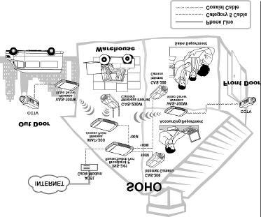
53 SOHO Applications 52

54 Enterprise Applications 53
55 I/O Connector Application 54
56 9 AUTO-RUN INSTALLATION Insert the CD-ROM into the CD-ROM drive to initiate the autorun program once completed a menu screen will appear as follows: 55
57 Then select the desired options from the menu buttons and they are as follows: User's Guide IPView Xplug Control Adobe Acrobat Browse CD Exit To preview the User's Guide in.pdf format for detailed information regarding the installation procedure for the Internet Camera simply click on the "User's Guide" button. To install the IPView application click on the "IPView" button to activate the installation procedure for the application program. Please refer to the next section for detailed information for installing IPView application. To install Xplug Control (ActiveX) plug-in program into your PC/Notebook click on the "Xplug Control" button to activate the installation procedure for the plug-in program. Please refer to the appendix for detailed information regarding Installation of Xplug Control (ActiveX) into your PC/Notebook or Web Server. If you do not have Adobe Acrobat Reader installed in your PC/Notebook click on the "Adobe Acrobat" button to activate the installation procedure. This will allow you to preview the User's Guide for the Internet Camera. 56
58 If you wish to glance the contents of the CD-ROM click on the "Browse CD" button and the content of the CD-ROM will be available for preview. To exit the CD-ROM just double click on the "EXIT" button. 57
59 10 IPVIEW APPLICATION INSTALLATION Installation Insert the CD-ROM into the CD-ROM drive to initiate the autorun program. Once completed a menu screen will appear as follows: 58

60 To install the IPView Application click on the "IPView" button to activate the installation procedure for the application program. Once executed a prompt will appear requesting the input of the desired language selection. Make the desired selection and click on OK to continue. The Welcome screen will appear. Click on the Next button to proceed with the installation. 59
61 The License Agreement prompt will appear as below. Read the details carefully and click on the Yes icon to continue with the installation procedure. A prompt will appear and in the Destination Location dialog box, you may click on Next to accept the recommended destination location or click on Browse to select another location. After 60


62 specifying the desired destination location, click on Next to proceed further. The Select Program Folder prompt will appear providing information of where the IPView application will be located, click on Next to continue. If you wish to modify your settings, click on Back to return to the previous screens. 61
63 Please wait until one of the two dialog box to appear, select either Yes, I want to restart my computer now and click on the Finish icon to restart the computer to complete the installation procedure. or click on the Finish icon to complete the installation procedure 62

64 After successfully installing the IPView, the application program for the Internet Camera is automatically installe d to \Programs\Files Directory. To start running the IPView click on windows Start Menu/Programs/IPView/IPView Once IPView is executed a Login prompt will appear, you must enter the default User Name: admin into the respective field and click on OK to log into the application. 63
65 Once login, the IPView application is executed and the IPView interface will appear as follows in the default List View format: 64
66 11 IPVIEW GETTING STARTED This section describes the operation of the IPView application User Interface with detailed procedures for using the application. IPView IPView is responsible for the management of preview, configuration, and searching of each camera. It is designed with a user-friendly interface for ease of control and navigation requirements as illustrated below. 65
67 List view format How to Change Password Change Password When IPView is used for the first time it is highly recommended to change the User Name and Password by the Administrator to constrain users access to the IPView application. Once the User Name and Password are defined only the Administrator has access to the management of IPView applications. This procedure should be done as soon as possible to prevent unauthorized usage of IPView application. 66

68 Once IPView is executed a Login prompt will appear, you must enter the default User Name : admin into the respective field and click on OK to log into the application. To change the User Name and Password select Tools > Options. The Options dialog box will appear as illustrated below. 67
69 The administrator needs to enter a User Name, Password and Confirm password into the respective fields. Once all the new details are entered click on the OK icon. Make sure to save any changes you have made to keep the information updated. Note: Alternatively you can click the Options icon use the hot key F10. as illustrated or How to Change IP Address Change IP Address To change an IP Address for a camera select Camera > Add. An Add Camera dialog box will appear as illustrated below. 68
70 Click on the Browse icon, the Browse Camera dialog box will appear with a blank screen as illustrated below. Click on the Search icon and IPView will detect and search all the available camera s that are installed on the local area network as depicted below: 69

71 You must highlight the camera you wish to change the IP Address and click on the Change IP icon and the Change IP Address dialog box will appear as depicted below: Enter the new IP Address along with the Subnet Mask and Default gateway into the respective fields and click on the OK icon and IPView will automatically change the IP Address. Make sure to save any changes you have made to keep the information updated. How to Add a Camera Add Camera To add a new camera select Camera > Add. An Add Camera dialog box will appear as illustrated below. 70


72 You can enter the IP Address of the camera in the specified field and click the Add icon to add a new camera. If the IP Address is entered incorrectly a dialog box will appear to notify the error. If you are unsure of the IP Address of the camera you can click on the Browse icon, the Browse Camera dialog box will appear with a blank screen as illustrated below. 71

73 Click on the Search icon and IPView will detect and search all the available camera s that are installed on the local area network as depicted below: You must highlight the camera you wish to add and click on the Add icon. The Add Camera dialog box will appear once again with the IP Address entered. Click on the Add icon and the camera will be automatically added into IPView list view format. Alternatively you can double click on the camera you wish to add and the Add Camera dialog box will appear once again with the IP Address entered. Click on the Add icon and the camera will be automatically added into IPView list view format. 72

74 If the Login Camera dialog box appears make sure to enter the correct User Name and Password and click on the OK icon and the camera will be added into IPView in list format. If the User Name and Password is entered incorrectly the camera will not be added into IPView. The above dialog box will appear only if administrator has already set the User Name and Password during the Web Configuration setting. If you forget to highlight the camera you wish to add a dialog box will appear to notify you of the error. Make sure to save any changes you have made to keep the information updated. Note 1: You are only able to add one camera at a time. 73

75 Note 2: Alternatively you can click the Add icon the hot key Shift+Ins. as illustrated or use How to Delete a Camera Delete Camera To delete a camera you must highlight the camera you wish to delete from IPView list view format. From the menu bar select Camera > Delete. A Delete Camera dialog box will appear and click on the Yes icon to delete the camera or click on No if you do not wish to delete the camera as illustrated below. Make sure to save any changes you have made to keep the information updated. Note: Alternatively you can click the Delete icon use the hot key Del. as illustrated or 74

76 How to View a Camera View Camera From the menu bar select View > 4 Cameras (other choices are available in 1 Camera, 9 Cameras and 16 Cameras viewing format) and the viewing screen will appear with the video image. Note: The icon on the upper left corner of the screen will appear with the camera number that is being displayed To return to the IPView list view format, click on the icon located on the upper left corner of the screen and a case sensitive menu will appear. Select List and the viewing image will return to the list view format. Note 1: A maximum of 16 cameras are available for viewing with the IPView application. 75
77 Note 2: Alternatively you can click the 1 Camera icon or use the hot key Ctrl+F3. For 4 Cameras as illustrated, 9 Cameras and 16 Cameras click the respective icon or use the hot key as follows Ctrl+F4, Ctrl+F5 and Ctrl+F6. To return to list view format use the hot key Ctrl+F1. How to Snap shot a Camera Snap shot Camera To snap shot a camera you must highlight the camera you wish to snap shot from the list view format. From the menu bar select Camera > Snap shot. A Save Image dialog box will appear for you to save the snap shot picture. A second alternative is from the viewing mode either 1, 4, 9, 16 cameras click on the icon located on the upper left corner of the screen and a case sensitive menu will appear and select the Snap shot icon. A Save Image dialog box will appear for you to save the snap shot picture. Note: Alternatively you can click the Snap shot icon or use the hot key F5. as illustrated 76
.")
78 How to Adjust the Property Setting Property Setting Property is initiated by selecting Camera > Property and a dialog box will appear allowing settings of Web Configuration and upgrade firmware (Please refer to the appendix for detailed information). The Camera Property dialog box will appear for you to select the desired options from the tab selections to Configure the camera as shown below. General Allows settings for the camera name, location and administrator information such as administrator ID and password. Please refer to the Web Configuration section under System Administration System for further details. 77

79 IP Assignment There are two options to select from the IP Assignment either Manually Assign or Assign Automatically Using. Please refer to the Web Configuration section under System Administration System for further details. 78

80 DNS DNS (Domain Name System) server is an Internet service that translates domain names into IP addresses. Enter at least one DNS IP Address. Please refer to the Web Configuration section under System Administration System for further details. 79

81 Wireless (Please skip this section if your camera is not wireless) Allows setting for connection mode, network name, wireless channel, and WEP key. Please refer to the Web Configuration section under System Administration System for further details. 80

82 Misc Allows setting for LED Control, ActiveX control location, and second port. Please refer to the Web Configuration section under System Administration System for further details. 81

83 Image Image provides the settings for the video image of the camera such as brightness, contrast, hue, resolution, compression, frame rate, and light freq. Please refer to the Web Configuration section under System Administration Image for further details. 82


84 Users Contain commands to allow system administrator to assign legal users who are permitted to monitor the camera from the remote site by Add or Delete user. To add a user click on the Add icon and the Add User dialog box will appear. Enter the User Name and Password into the specific field. Select the I/O Output Control to give users the privilege of accessing the I/O Output Control. 83

85 To delete a user, select the user and click on the Delete icon. Please refer to the Web Configuration section under System Administration Users for further details. Date/Time Contain commands for setting the camera s time and date to provide correct time information to users who might be thousands of miles away in the remote site by selecting Synchronized with Time Server or Set Manually. Please refer to the Web Configuration section under System Administration TimeDate for further details. 84

86 Trigger 1 Contains commands for setting the I/O Trigger connectors providing the physical interface for 1 digital output and 1 digital input that is used for connecting a diversity of external alarm devices to the camera such as IR-Sensor and alarm relay. Please refer to the Web Configuration section under System Administration Trigger for further details. 85

87 Trigger 2 Contains commands for setting the I/O Trigger connectors providing the physical interface for 1 digital output and 1 digital input that is used for connecting a diversity of external alarm devices to the camera such as IR-Sensor and alarm relay. Please refer to the Web Configuration section under System Administration Trigger for further details. 86

88 Information Displays information about the camera such as the model, firmware version, MAC address, and IP address. Please refer to the Web Configuration section under System Administration Information for further details. 87

89 Tools Contains commands for reset the camera and update firmware (please refer to the appendix for detailed information). Please refer to the Web Configuration section under System Administration Tools for further details on reset. Make sure to save any changes you have made to keep the information updated. Note: Alternatively you can click the Property icon or use the hot key F2. as illustrated 88

90 Menu Bar The menu bar provides easier access for users to navigate the IPView with different selections along with hot key capabilities as follows: Menu Bar - File File on the menu bar provides New, Open, Save, Save As and Exit for users to create new files, open existing files, save files, and exit the IPView as depicted below. Menu Bar View View on the menu bar provide users with management capabilities for Columns, List, Camera and Refresh. You can view Camera in 1 Camera, 4 Cameras, 9 Cameras, 16 Cameras. The View menu bar is pictured below. 89

91 Columns When Columns is launched a dialog box will appear allowing the option to choose the columns one would like to display in List View as illustrated below. Viewing Format You can view the format in List view. The List viewing format allows easy management and control of each camera. List View List view is illustrated below for your reference. You are able to list all the cameras and their properties such as the camera 90
92 name, IP address, user name, and location will be displayed for ease of control and management. Note: Right click the mouse pad on any kind of the camera will bring up a context sensitive menu which shows the actions you can apply to the selected camera. Double click on the desired camera will bring up the Property dialog box. To update camera list view just click on the Refresh icon for Real Time Data and the latest information. 91
93 Menu Bar - Camera Camera on the menu bar provides options to manage the camera. One can Add additional Camera with a maximum of 16 Camera allowed for viewing. Through the management function one can Delete a camera, manage the Property, Enable for real time and take a Snap shot image. The menu bar is illustrated below: Enable Function By default the video image is enabled. There will be a check next to the Enable command to show that the Enable function is working. To disable real-time image select Camera > Enable and real-time video image will stop and shutdown. Menu Bar - Tools "Tools" on the menu bar allows administrator management of the security settings such as User Name and Password to gain access into the IPView application. From the menu bar select 92
94 "Tools > "Options" and a dialog box will appear. Administrator can change the User Name and Password for security settings to access the application. Menu Bar - Help Help on the menu bar provides Contents and About to instruct users how to operate the camera in HTLM format. From the menu bar select Help and can choose either Contents or About as depicted below: 93
95 IPView Icon Description Open a new file. Alternatively the hot key is Ctrl+N. Open an existing file. Alternatively the hot key is Ctrl+O. Save a file. Alternatively the hot key is Ctrl+S. List view format. Alternatively the hot key is Ctrl+F1. 1 Camera view format. Alternatively the hot key is Ctrl+F3. 4 Camera view format. Alternatively the hot key is Ctrl+F4. 9 Camera view format. Alternatively the hot key is Ctrl+F5. 16 Camera view format. Alternatively the hot key is Ctrl+F6. Refresh IPView application. Alternatively the hot key is F12. Add a camera. Alternatively the hot key is Shift+Ins. Delete a camera. Alternatively the hot key is Del. 94
96 Property setting to configure the camera. Alternatively the hot key is F2. Snap shot to capture a single still image. Alternatively the hot key is F5. Options to modify the User Name and Password for IPView. Alternatively the hot key is F10. 95

97 Context Sensitive Menu In list view format by highlighting a camera and right clicking the mouse pad will bring up a context sensitive menu for features such as Add, Delete, Property, Enable, and Snap shot. 96

98 In view mode format click on the icon located on the upper left corner of the screen and a case sensitive menu will appear as illustrated below. Features such as Enable, Snap shot, List, 1 Camera, 4 Cameras, 9 Cameras, 16 Cameras, Previous Page and Next Page will be available. 97

99 12 UNINSTALL IPVIEW APPLICATION Click on windows Start Menu / Settings / Control Pane l. A prompt screen will be displayed like the one below and double click on the Add/Remove Programs icon. 98

100 From the Add/Remove Programs Properties Menu, select IPView as illustrated below. Then click on the Remove button. A new prompt screen will be displayed like the one below confirming the removal. Click on the OK icon to continue the process or click on the Cancel icon to reject the uninstall process. 99
101 The InstallShield Wizard prompt will appear and click on Finish to complete the uninstallation procedure. 100
102 APPENDIX A Frequently Asked Questions Internet Camera Features Q: What is a Internet Camera? A: The Internet Camera is a standalone system connecting directly to an Ethernet or Fast Ethernet network. It is different from the conventional PC Camera, the Internet Camera is an allin-one system with built-in CPU and web-based solutions providing a low cost solution that can transmit high quality video images for monitoring. The Internet Camera can be managed remotely, accessed and controlled from any PC/Notebook over the Intranet or Internet via a web browser. Q: What is the maximum number of users that can be allowed to access the Internet Camera simultaneously? A: Maximum number of users that can log onto the Internet Camera at the same time is 64. Please keep in mind the overall performance of the transmission speed will slow down when many users are logged on. 101
103 Q: What algorithm is used to compress the digital image? A: The Internet Camera utilizes the JPEG image compression technology providing high quality images for users. JPEG is adopted since it is a standard for image compression and can be applied to various web browser and application software without the need to install extra software. Internet Camera Installation Q: Can the Internet Camera be used out-doors? A: The Internet Camera is not weatherproof. It needs to be equipped with a weatherproof case to be used outdoors and it is not recommended. Q: What network cabling is required for the Internet Camera? A: The Internet Camera uses Category 5 UTP cable allowing 10 Base-T and 100 Base-T networking. Q: Can the Internet Camera be setup as a PC-cam on the computer? A: No, the Internet Camera is an Internet Camera used only on Ethernet and Fast Ethernet network. Q: Can the Internet Camera be connected on the network if it consists of only private IP addresses? A: The Internet Camera can be connected to LAN with private IP addresses. 102
104 Q: Can the Internet Camera be installed and work if a firewall exists on the network? A: If a firewall exists on the network, port 80 is open for ordinary data communication. However, since the Internet Camera transmits image data, the default port 8481 is also required. Therefore, it is necessary to open port 8481 of the network for remote users to access the Internet Camera. 103
105 B PING Your IP Address The PING (Packet Internet Groper) command can determine whether a specific IP address is accessible by sending a packet to the specific address and waiting for a reply. It can also provide a very useful tool to confirm if the IP address conflicts with the Internet Camera over the network. Follow the step-by-step procedure below to utilize the PING command but first you must disconnect the Internet Camera from the network. Start a DOS window. Type ping x.x.x.x, where x.x.x.x is the IP address of the Internet Camera. The succeeding replies as illustrated below will provide useful explanation to the cause of the problem with the Internet Camera IP address. 104
106 C Trouble Shooting Q: I cannot access the Internet Camera from a web browser? A1: The possible cause might be the IP Address for the Internet Camera is already being used by another device. To correct the possible problem, you need to first disconnect the Internet Camera from the network. Then run the PING utility (follow the instructions in Appendix B - PING Your IP Address). A2: Another possible reason is the IP Address is located on a different subnet. To fix the problem, run the PING utility (follow the instructions in Appendix B - PING Your IP Address). If the utility returns no response or similar, the finding is probably correct, then you should proceed as follows:- In Windows 95/98/2000 and Windows NT, double check the IP Address of the Internet Camera is within the same subnet as your workstation. Click Start, Setting, Control Panel, and the Network icon. Select TCP/IP from the Network dialog box and from the TCP/IP Properties dialog box click on Specify an IP address. If the Internet Camera is situated on a different subnet than your workstation, you will not be able to set the IP address from this workstation. To verify make sure the first 3 sections of the IP address of the Internet Camera corresponds to the first 3 sections of the workstation. Therefore the IP address of the Internet Camera must be set from a workstation on the same subnet. 105
107 A3: Other possible problems might be due to the network cable. Try replacing your network cable. Test the network interface of the product by connecting a local computer to the unit, utilizing a standard Crossover (hub to hub) Cable. If the problem is not solved the Internet Camera might be faulty. Q: Why does the Power LED not light up constantly? A: The power supply used might be at fault. Confirm that you are using the provided power supply DC 5V for the Internet Camera and verify that the power supply is well connected. Q: Why does the LAN LED not light up properly? A1: There might be a problem with the network cable. To confirm that the cables are working, PING the address of a know device on the network. If the cabling is OK and your network is reachable, you should receive a reply similar to the following ( bytes = 32 time = 2 ms). A2: The network device utilized by the Internet Camera is not functioning properly such as hubs or switches. Confirm the power for the devices are well connected and functioning. Q: Why does the Internet Camera work locally but not externally? A1: Might be caused from the firewall protection. Need to check the Internet firewall with your system administrator. A2: The default router setting might be a possible reason. Need to double check if the configuration of the default router settings is required. 106
108 Q: Why does a series of broad vertical white line appears through out the image? A: A likely issue is that the CMOS sensor becomes overloaded when the light source is too bright such as direct exposure to sunlight or halogen light. You need to reposition the Internet Camera into a more shaded area immediately as this will damage the CMOS sensor. Q: There is bad focus on the Internet Camera, what should be done? A1: The focus might not be correctly adjusted for the line of sight. You need to adjust the Internet Camera focus manually as described in Adjust Internet Camera Focus. A2: There is no adaptor fitted with your C-type lens. If you have previously changed the supplied CS-type lens, you may have unintentionally installed a C-type lens without fitting the adaptor first. Q: Noisy images occur how can I solve the problem? A1: The video images might be noisy if the Internet Camera is used is a very low light environment. To solve this issue you need more lighting. Q: There is poor image quality, how can I improve the image? A1: A probable cause might be the incorrect display properties configuration for your desktop. You need to open the Display Properties on your desktop and configure your display to show at least colors for example at least 16-bit. 107
109 Note: Applying only 16 or 256 colors on your computer will produce dithering artifacts in the image. A2: The configuration on the Internet Camera image display is incorrect. Through the Web Configuration Image section you need to adjust the image related parameter for improve images such as brightness, contrast, hue and light frequency. Please refer to the Web Configuration section for detail information. Q: There are no images available through the web browser? A: The ActiveX might be disabled. If you are viewing the images from Internet Explorer make sure ActiveX has been enabled in the Internet Options menu. Alternatively, you can use the Java Applet for viewing the required images. 108
110 D I/O Connector I/O Connector Definition for the Internet Camera An 8-pole connector is provided for auxiliary IO connections to the Internet Camera. The IO connector provides the physical interface for 2 digital output and 2 digital input that is used for connecting a diversity of external alarm devices to the Internet Camera such as IR-Sensor and alarm relay. The digital input is used for connecting external alarm devices and once triggered images will be taken and ed. The supported transistor output can give a maximum of DC 5V to the externally connected alarm devices and once triggered the current will activate the devices. In 11 In 11 & In 12 is a pair for digital input. It works at voltage 5V In 12 In 21 In 21 & In 22 is a pair for digital input. It works at voltage 5V In 22 Out 1 + Out 1 - & Out 1 + is a pair for digital out. The out put voltage is 5 Out 1 - V and maximum current is 100 ma Out 2 + Out 2 - & Out 2 + is a pair for digital out. The out put voltage is 5 Out 2 - V and maximum current is 100 ma 109
111 I/O Schematic Diagram Warning 1. When connecting a device to the Input connector, the device must be a passive component without voltage and electrical current. 2. When connecting other devices through the Output connector, please make sure the maximum current of DC 5V, 100mA is strictly observed. 3. Any failure of the above two points might cause serious Note: damage to the camera. Through the Web Configuration in the Trigger section, you must first enable the trigger function. Please refer to the Web Configuration section for detailed information. 110

112 E Upgrade Firmware User s can update firmware from the IPView application. Select Camera > Properties and the Camera Property dialog box will appear. Select the Tools tab and enter the full path of the firmware binary file name in the Update Firmware field or you can click on the Browse icon to select the file. Once the firmware file is entered click on the Update icon to proceed with the updating process. Once completed click on the OK icon as illustrated below Warning During firmware update process please make sure no interruptions will occur as it might possibly cause serious damage to the Internet Camera 111


113 F Time Zone Table 112


114 113
115 G Xplug Control Installation Installation To Web Server Important Information It is highly recommended to install the Xplug Control application to the Web Server for IE 5.0. It must be installed to a Public Domain with Fixed IP address. 1. Installation: Copy the xplug.ocx file to any WEB Server table. 2. Setting (Configuration): From the Web Configuration menu select System and under the Loading ActiveX From input web server location ( server location.com/). Once the settings are completed the user now is able to access the Internet Camera from the web browser by selecting the image view ActiveX mode. 114

116 Installation To Local PC Insert the CD-ROM into the CD-ROM drive to initiated the autorun program once completed a menu screen will appear as follows: To install Xplug Control click on the "Xplug Control" button to activate the installation procedure for the plug-in program. 115
117 Once executed a prompt will appear requesting the input of the desired language selection. Make the desired selection and click on OK to continue. The Welcome screen will appear. Click on the Next button to proceed with the installation. 116

118 The License Agreement prompt will appear as below. Read the details carefully and click on the Yes icon to continue with the installation procedure. Click on the Finish button to complete Setup of the Xplug Control Utility program for the Internet Camera. 117
D-Link. DCS-1000W 2.4GHz Wireless Internet Camera Manual
 D-Link DCS-1000W 2.4GHz Wireless Internet Camera Manual FCC Warning This device complies with Part 15 of the FCC Rules. Operation is subject to the following two conditions: (1) this device may not cause
Internet Camera Quick Installation Guide
 Internet Camera Quick Installation Guide Rev. 01 (Dec, 2001) Q20011203 Printed In Taiwan Table of Content INTRODUCTION...2 SYSTEM REQUIREMENT...3 INTERNET CAMERA... 3 Network:...3 Recommended PC or Notebook
DCS-900. Manual. Internet Camera. Version Building Networks for People (10/04/04)
") DCS-900 Internet Camera Manual Version 1.50 Building Networks for People (10/04/04) Contents Package Contents...3 Introduction...4 Hardware Installation...9 Security...10 Using the Setup Wizard... 11 DCS-900
DCS-900 Internet Camera Manual Version 1.50 Building Networks for People (10/04/04) Contents Package Contents...3 Introduction...4 Hardware Installation...9 Security...10 Using the Setup Wizard... 11 DCS-900
IPCam SECURE300W User s Manual
 IPCam SECURE300W User s Manual Version 1.0 Index INTRODUCTION... 2 FEATURES AND BENEFITS... 2 PACKAGE CONTENTS... 4 SYSTEM REQUIREMENTS... 5 HARDWARE OVERVIEW... 6 HARDWARE INSTALLATION... 11 SECURITY...
User s Manual. Wireless Internet Camera. Model No.: SP5520K
 User s Manual Wireless Internet Camera Model No.: SP5520K http://www.micronet.info - 0 - FCC Certifications This product has been tested and found to comply with the limits for a Class B digital device
(Wireless) IP Camera LN-402/WL-400. Full Manual
 IP Camera LN-402/WL-400. Full Manual") (Wireless) IP Camera LN-402/WL-400 Full Manual About This Guide This manual describes Internet Camera, including a description of the features, as well as the installation procedures and web configuration.
(Wireless) IP Camera LN-402/WL-400 Full Manual About This Guide This manual describes Internet Camera, including a description of the features, as well as the installation procedures and web configuration.
Pan/Tilt Internet Camera
 Pan/Tilt Internet Camera User s Guide Rev. 2.1 (Aug., 2005) Made in Taiwan 1 TABLE OF CONTENTS ABOUT THIS GUIDE...4 1. INTRODUCTION...5 FEATURES AND BENEFITS...6 UNPACKING THE PACKAGE...8 SYSTEM REQUIREMENT...9
TABLE OF CONTENTS ABOUT THIS GUIDE
 TABLE OF CONTENTS ABOUT THIS GUIDE...3 INTRODUCTION...4 FEATURES AND BENEFITS...5 UNPACKING THE PACKAGE...7 SYSTEM REQUIREMENT...8 PHYSICAL DESCRIPTION...9 HARDWARE INSTALLATION...14 ATTACHING THE CAMERA
Print Server. User s Manual. Rev. 01 (April, 2004) Made In Taiwan
 Made In Taiwan") Print Server User s Manual Rev. 01 (April, 2004) Made In Taiwan TABLE OF CONTENTS ABOUT THIS GUIDE... 4 INTRODUCTION... 5 PACKAGE CONTENTS... 6 SYSTEM REQUIREMENTS... 6 GENERAL FEATURES... 7 PRODUCT VIEW...
Print Server User s Manual Rev. 01 (April, 2004) Made In Taiwan TABLE OF CONTENTS ABOUT THIS GUIDE... 4 INTRODUCTION... 5 PACKAGE CONTENTS... 6 SYSTEM REQUIREMENTS... 6 GENERAL FEATURES... 7 PRODUCT VIEW...
Internet Camera. User s Manual ICA-110/ICA-110W. Version 1.0
 Internet Camera ICA-110/ICA-110W User s Manual Version 1.0 Copyright Copyright (C) 2005 PLANET Technology Corp. All rights reserved. The products and programs described in this User s Manual are licensed
USB 2.0 Print Server. User s Manual. Rev. 01 (Jan, 2004) Made In Taiwan
 Made In Taiwan") USB 2.0 Print Server User s Manual Rev. 01 (Jan, 2004) Made In Taiwan TABLE OF CONTENTS ABOUT THIS GUIDE... 4 INTRODUCTION... 5 PACKAGE CONTENTS... 6 SYSTEM REQUIREMENTS... 6 GENERAL FEATURES... 7 PRODUCT
USB 2.0 Print Server User s Manual Rev. 01 (Jan, 2004) Made In Taiwan TABLE OF CONTENTS ABOUT THIS GUIDE... 4 INTRODUCTION... 5 PACKAGE CONTENTS... 6 SYSTEM REQUIREMENTS... 6 GENERAL FEATURES... 7 PRODUCT
wificam User's Guide Report Version: Date: November
 User's Guide Report Version: 2.0.3 Date: November 9 2004 3JTech Co., Ltd. 342 Fu-Hsing N. Rd., 2F Taipei, Taiwan Tel: +886-2-2500 6919 e-mail: info@3jtech.com.tw 1 Revision History Version Date Changes
SOHO NETWORK IP CAMERA USER MANUAL
 SOHO NETWORK IP CAMERA USER MANUAL MODEL 503365 INT-503365-UM-0407-02 Contents section page 1. Introduction... 1 2. Package Contents... 2 3. System Requirements... 2 4. Hardware Installation... 3 4.1 LED
LevelOne FCS Mbps IP Network Camera User s Manual
 LevelOne FCS-1020 100Mbps IP Network Camera User s Manual Contents 1. Introduction...3 2. Package Content...3 3. System Requirement...3 4. Hardware Installation...4 4.1. LED and Focusing...4 4.2. Camera
Fast Ethernet Print Server 1 Parallel, 2 USB
 Fast Ethernet Print Server 1 Parallel, 2 USB User s Manual Rev. 01 (Nov, 2005) Made In Taiwan TABLE OF CONTENTS ABOUT THIS GUIDE... 4 INTRODUCTION... 5 PACKAGE CONTENTS... 6 SYSTEM REQUIREMENTS... 6 GENERAL
Wireless Network Video Recorder
 LD2R/LD2R500 Wireless Network Video Recorder User Guide Version 1.0 PREFACE Thank you for purchasing the Wireless Network Video Recorder, an IP based device that installed on your network, which can be
Internet Camera. User Manual
 Internet Camera User Manual Version: 1.1 Released Date: Dec., 2004 Contents 1. Introduction... 3 2. Package Content... 3 3. System Requirement... 3 4. Hardware Installation... 4 4.1. LED and Focusing...4
IP Camera. User Manual
 501583 IP Camera User Manual Version: 1.2 Released Date: June., 2005 Contents 1. Introduction... 3 2. Package Content... 3 3. System Requirement... 3 4. Hardware Installation... 4 4.1. LED and Focusing...4
DI-704P Ethernet Broadband Router. Ethernet (Straight Through) Cable. 5V DC Power Adapter
 Cable. 5V DC Power Adapter") 1 This product can be set up using any current Web browser, i.e., Internet Explorer or Netscape Navigator. DI-704P Ethernet Broadband Router and Print Server Before You Begin 1. If you purchased this router
1 This product can be set up using any current Web browser, i.e., Internet Explorer or Netscape Navigator. DI-704P Ethernet Broadband Router and Print Server Before You Begin 1. If you purchased this router
Pan/Tilt Wireless Internet Camera User s Guide
 Pan/Tilt Wireless Internet Camera User s Guide Version 1.1 1 TABLE OF CONTENTS ABOUT THIS GUIDE... 4 1. INTRODUCTION... 5 GENERAL FEATURES AND BENEFITS... 6 UNPACKING THE PACKAGE... 9 SYSTEM REQUIREMENT...
One DCS-900 Internet Camera. One Installation CD-ROM (containing Drivers, Installation Guide, Software, and Manual) One Camera Stand
 One Camera Stand") This product can be set up using any current Web browser, i.e., Internet Explorer 6.0 or Netscape Navigator 7.0 DCS-900 Fast Ethernet Internet Camera Before You Begin You must have at least the following:
This product can be set up using any current Web browser, i.e., Internet Explorer 6.0 or Netscape Navigator 7.0 DCS-900 Fast Ethernet Internet Camera Before You Begin You must have at least the following:
Mega 100WR ADSL 2+ Router - Easy Start
 Mega 100WR ADSL 2+ Router - Easy Start Mega 100WR ADSL 2+ Router - Easy Start Chapter 1 Introduction Thank you for purchasing a Mega 100WR Router. This Easy start guide is a complete guide to configuring
Conceptronic C100BRS4H Quick Installation Guide. Congratulations on the purchase of your Conceptronic 4-ports Broadband Router.
 Conceptronic C100BRS4H Quick Installation Guide Congratulations on the purchase of your Conceptronic 4-ports Broadband Router. The enclosed Hardware Installation Guide gives you a step-by-step explanation
Wireless USB Port Multi-Functional Printer Server. Model # AMPS240W. User s Manual. Ver. 1A
 Wireless USB 2.0 1-Port Multi-Functional Printer Server Model # AMPS240W User s Manual Ver. 1A Table of Contents 1 Introduction...3 1.1 Package Contents... 3 1.2 System Requirements... 3 2 Multi-Functional
AirCruiser G Wireless Router GN-BR01G
 AirCruiser G Wireless Router GN-BR01G User s Guide i Contents Chapter 1 Introduction... 1 Overview...1 Features...1 Package Contents...2 AirCruiser G Wireless Router Rear Panel...2 AirCruiser G Wireless
Internet Camera ICA-102/ICA-102W
 Internet Camera ICA-102/ICA-102W User s Manual Copyright Copyright (C) 2004 PLANET Technology Corp. All rights reserved. The products and programs described in this User s Manual are licensed products
Ethernet (CAT5 UTP/Straight-Through) Cable. 5V DC Power Adapter
 Cable. 5V DC Power Adapter") 1 This product can be set up using any current web browser, i.e., Internet Explorer 6 or Netscape Navigator 6.2.3. Before You Begin Check Your Package Contents DI-824VUP+ 2.4GHz Wireless VPN Router and
1 This product can be set up using any current web browser, i.e., Internet Explorer 6 or Netscape Navigator 6.2.3. Before You Begin Check Your Package Contents DI-824VUP+ 2.4GHz Wireless VPN Router and
TABLE OF CONTENTS COPYRIGHT INTRODUCTION...3 PRODUCT OVERVIEW...3 COMPONENTS AND FEATURES...3 HARDWARE INSTALLATION
 TABLE OF CONTENTS COPYRIGHT...2 1. INTRODUCTION...3 PRODUCT OVERVIEW...3 COMPONENTS AND FEATURES...3 HARDWARE INSTALLATION...3 2. MFP SERVER INSTALLATION...5 PREPARATION...5 CONFIGURATION SOLUTION TABLE...5
System Requirements. Package Contents
 System Requirements System Requirements Computer with Windows Vista or XP SP2 PC with 1.3GHz or above; at least 128MB RAM Internet Explorer 6.0 or Netscape Navigator 7.0 and above Existing 10/100 Ethernet-based
1 Hardware Installation
 1 Hardware Installation 1.1 Choosing the Best Location for Wireless Operation Many environmental factors may affect the effective wireless function of the DSL Router. If this is the first time that you
LevelOne Broadband Routers
 LevelOne Broadband Routers FBR-1100TX FBR-1400TX FBR-1401TX FBR-1700TX User's Guide TABLE OF CONTENTS CHAPTER 1 INTRODUCTION... 1 Features of your LevelOne Broadband Router... 1 Package Contents... 4
The Administration Tab - Diagnostics
 The Administration Tab - Diagnostics The diagnostic tests (Ping and Traceroute) allow you to check the connections of your network components. Ping Test. The Ping test will check the status of a connection.
Longshine Technologie Europe GmbH
 Longshine Technologie Europe GmbH www.longshine.de TABLE OF CONTENTS COPYRIGHT...2 1. INTRODUCTION...3 PRODUCT OVERVIEW...3 COMPONENTS AND FEATURES...3 HARDWARE INSTALLATION...3 2. MFP SERVER INSTALLATION...5
IP-001T Video Server Products Series. User Manual & Installation Guide
 Page 1 of 29 IP-001T Video Server Products Series User Manual & Installation Guide Version: 1.0 Page 2 of 29 Table of Contents TABLE OF CONTENTS...2 WHAT IS VIDEO SERVER?...3 PRODUCT FEATURES...3 2. PHYSICAL
DSL-G624T. Wireless ADSL Router. If any of the above items is missing, please contact your reseller. This product can be set up using any
 This product can be set up using any current web browser, i.e., Internet Explorer 6x or Netscape Navigator 7x. DSL-G624T Wireless ADSL Router Before You Begin 1. If you purchased this Router to share your
C1002 IP Camera. Quick Installation Guide. Solwise Ltd., 1
 C1002 IP Camera Quick Installation Guide Solwise Ltd., www.solwise.co.uk, sales@solwise.co.uk 1 Trademarks and/or registered trademarks are the property of their respective owners The information presented
54Mbps Pocket Wireless Access Point (WL-330g)
") 54Mbps Pocket Wireless Access Point (WL-330g) Copyright 2004 ASUSTeK COMPUTER INC. All Rights Reserved. Contents Conventions... 2 Welcome!... 3 Package contents... 3 System requirements... 3 Device installation...
54Mbps Pocket Wireless Access Point (WL-330g) Copyright 2004 ASUSTeK COMPUTER INC. All Rights Reserved. Contents Conventions... 2 Welcome!... 3 Package contents... 3 System requirements... 3 Device installation...
LevelOne. User Manual. WAP Mbps PoE Wireless AP V3.0.0
 LevelOne WAP-0005 108Mbps PoE Wireless AP User Manual V3.0.0 i TABLE OF CONTENTS CHAPTER 1 INTRODUCTION... 1 FIGURE 1: WIRELESS ACCESS POINT... 1 FEATURES OF YOUR WIRELESS ACCESS POINT... 1 Security Features...
Longshine Technologie Europe GmbH LCS-MFP101-2 Multifunction Printserver
 Longshine Technologie Europe GmbH LCS-MFP101-2 Multifunction Printserver www.longshine.de TABLE OF CONTENTS COPYRIGHT...2 1. INTRODUCTION...3 PRODUCT OVERVIEW...3 COMPONENTS AND FEATURES...3 HARDWARE INSTALLATION...3
Easy Start Guide. Solwise SAR-600 range ADSL2+ Routers
 Guide Solwise SAR-600 range ADSL2+ Routers Covers the following models using RouterTech Firmware 2.1: Single LAN Port, SAR-600E Four LAN Port, SAR-600ER Four LAN Port with USB & 11g Wireless, SAR-600EW
TABLE OF CONTENTS ABOUT THIS GUIDE... 4
 TABLE OF CONTENTS ABOUT THIS GUIDE... 4 INTRODUCTION... 5 PACKAGE CONTENTS... 6 SYSTEM REQUIREMENTS... 6 GENERAL FEATURES... 7 PRODUCT VIEW... 8 HARDWARE INSTALLATION... 10 NETWORKING APPLICATION... 10
Minimum System Requirements. Package Contents
 Ver. 1.00 DCS-6111 System Requirements Minimum System Requirements Internet Explorer 6.x or above Windows XP or Windows Vista 1.7GHz processor or higher 256MB of RAM 1 Ethernet connection Package Contents
F Series Indoor Fixed IP Camera. Quick Start Guide
 F Series Indoor Fixed IP Camera Quick Start Guide Welcome Thank you for purchasing our IP camera! Before install and use the IP camera, please read the following section carefully. Please keep this start
DI GHz Wireless Router
 This product can be set up using any current web browser, i.e., Internet Explorer 6 or Netscape Navigator 6.2.3. DI-514 2.4GHz Wireless Router Before You Begin 1. If you purchased this router to share
CMOS/Mega-Pixel CMOS/CCD Internet Camera ICA-230 / ICA-M230 / ICA-501. Quick Installation Guide
 CMOS/Mega-Pixel CMOS/CCD Internet Camera ICA-230 / ICA-M230 / ICA-501 Quick Installation Guide Table of Contents Chapter 1. Introduction... 3 1.1 Before Installation... 3 1.2 System Requirements... 3 1.3
LevelOne FBR User s Manual. 1W, 4L 10/100 Mbps ADSL Router. Ver
 LevelOne FBR-1416 1W, 4L 10/100 Mbps ADSL Router User s Manual Ver 1.00-0510 Table of Contents CHAPTER 1 INTRODUCTION... 1 FBR-1416 Features... 1 Package Contents... 3 Physical Details... 3 CHAPTER 2
NET101. RS232 / RS422 / RS485 to Ethernet Converter. User s Manual. Version 1.2
 NET101 RS232 / RS422 / RS485 to Ethernet Converter User s Manual Version 1.2 Copyright Information Copyright 2004-2005, Mega System Technologies, Inc. All rights reserved. Reproduction without permission
Content 1 OVERVIEW HARDWARE DESCRIPTION HARDWARE INSTALLATION PC CONFIGURATION GUIDE... 5 WEB-BASED MANAGEMENT GUIDE...
 Content 1 OVERVIEW...1 1.1FEATURES...1 1.2 PACKETCONTENTS...3 1.3 SYSTEM REQUIREMENTS... 1.4 FACTORY DEFAULTS...4 1.5 WARNINGS AND CAUTIONS...4 2 HARDWARE DESCRIPTION... 6 3 HARDWARE INSTALLATION...8 4
Network USB over IP Server With 1-USB2.0 Port. User Manual V1.0
 Network USB over IP Server With 1-USB2.0 Port User Manual V1.0 1 2 TABLE OF CONTENTS COPYRIGHT...4 1. INTRODUCTION...5 PRODUCT OVERVIEW...5 COMPONENTS AND FEATURES...5 HARDWARE INSTALLATION...5 2. THE
IPC98 Network Camera Module
 IPC98 User s Guide Rev 0 Mar 25, 2009 Rm 802, Nan Fung Ctr, Castle Peak Rd, Tsuen Wan, NT, Hong Kong Tel:2498 6248 Fax:2414 3050 Email: sales@comedia.com.hk http://www.comedia.com.hk 1 Table Of Contents
Multi-Homing Broadband Router. User Manual
 Multi-Homing Broadband Router User Manual 1 Introduction... 4 Features... 4 Minimum Requirements... 4 Package Content... 4 Note... 4 Get to know the Broadband Router... 5 Back Panel... 5 Front Panel...
DCS Manual. Audio Internet Camera. Version Building Networks for People (10/04/04)
") DCS-2000 Audio Internet Camera Manual Version 3.40 Building Networks for People (10/04/04) 2 Contents Contents of Package...3 Introduction...4 Features and Benefits...4 Connections...6 Hardware Installation...8
DCS-2000 Audio Internet Camera Manual Version 3.40 Building Networks for People (10/04/04) 2 Contents Contents of Package...3 Introduction...4 Features and Benefits...4 Connections...6 Hardware Installation...8
DCS Manual. 2-Way Audio Internet Camera with Digital Zoom. Version 1.3. Building Networks for People (12/04/07)
") DCS-3220 2-Way Audio Internet Camera with Digital Zoom Manual Version 1.3 Building Networks for People (12/04/07) 2 Contents Contents of Package...3 Introduction...4 Features and Benefits...4 Connections...6
DCS-3220 2-Way Audio Internet Camera with Digital Zoom Manual Version 1.3 Building Networks for People (12/04/07) 2 Contents Contents of Package...3 Introduction...4 Features and Benefits...4 Connections...6
Part # Quick-Start Guide. SpeedStream 4200 Modem PPPoE Modem Router
 Part # 007-0-00 Quick-Start Guide SpeedStream 00 Modem PPPoE Modem Router Before you begin, Verify that the following items came with your DSL kit: Step > Install Line Filters 7 SpeedStream Device Documentation
DI-808HV 8-Port Broadband VPN Router
 This product can be set up using any current web browser, i.e., Internet Explorer 6 or Netscape Navigator 6.2.3. DI-808HV 8-Port Broadband VPN Router 1. Thank you for purchasing this Router to share your
Wireless-G Router User s Guide
 Wireless-G Router User s Guide 1 Table of Contents Chapter 1: Introduction Installing Your Router System Requirements Installation Instructions Chapter 2: Preparing Your Network Preparing Your Network
CHAPTER 1. Welcome to Grand IP Camera III
 CHAPTER 1 Welcome to Grand IP Camera III 3. Remote view through the IE browser, simply type in the IP address. 4. 6 infrared LEDs provide imaging in the dark. 5. Many Valuable Internet services: Email,
Contents. Introduction Overview Range of Application Product Description Operation Environment...
 Contents Introduction... 3 1. Overview... 4 1.1 Range of Application... 4 1.2 Product Description... 4 1.3 Operation Environment... 5 2. Device Connection... 5 3. Device Operation Instructions... 6 3.1
Zavio P5111/ P5116/ P5210 Quick Installation Guide
 86085M2000010 Zavio P5111/ P5116/ P5210 Quick Installation Guide Installation Steps Please follow the installation steps below to set up your P5111 / P5116/ P5210 Day/Night Pan/Tilt IP Camera. Check the
CHAPTER 7 ADVANCED ADMINISTRATION PC
 ii Table of Contents CHAPTER 1 INTRODUCTION... 1 Broadband ADSL Router Features... 1 Package Contents... 3 Physical Details... 4 CHAPTER 2 INSTALLATION... 6 Requirements... 6 Procedure... 6 CHAPTER 3 SETUP...
OUTDOOR IR NETWORK CAMERA Series
 OUTDOOR IR NETWORK CAMERA Series INSTALLATION GUIDE Please read instructions thoroughly before operation and retain it for future reference. 1. OVERVIEW 1.1 Package Content Network camera Installation
Broadband Router DC-202. User's Guide
 Broadband Router DC-202 User's Guide Table of Contents CHAPTER 1 INTRODUCTION... 1 Broadband Router Features... 1 Package Contents... 3 Physical Details...3 CHAPTER 2 INSTALLATION... 5 Requirements...
Installation Procedure Windows NT with Netscape 4.x
 Installation Procedure Windows NT with Netscape 4.x Printer Friendly Version [ PDF 232K ] Before You Begin Before proceeding with the installation of a SOHO 6 appliance, you must have the following: A
IP / CCTV OUTDOOR SPEED DOME CAMERA
 242Z IP / CCTV OUTDOOR SPEED DOME CAMERA Quick Installation Guide All lead-free products offered by the company comply with the requirements of the European law on the Restriction of Hazardous Substances
IP Power 9258 HP User Manual Firmware Version: 1.1 Date Released: 09/16/2009
 IP Power 9258 HP User Manual Firmware Version: 1.1 Date Released: 09/16/2009-1 - Warning: Any changes made to this equipment without permission may cause damages to the device! IMPORTANT NOTICE 1. IP Power
DFL-700. Check Your Package Contents. Network Security Firewall
 This product can be set up using any current web browser, i.e., Internet Explorer 6 or Netscape Navigator 6. DFL-700 Network Security Firewall Before You Begin If you purchased this Network Security Firewall
BiPAC 5200 Series. (802.11g) ADSL2+ Modem/Router. Quick Start Guide
 ADSL2+ Modem/Router. Quick Start Guide") BiPAC 5200 Series (802.11g) ADSL2+ Modem/Router Quick Start Guide Billion BiPAC 5200 Series ADSL2+ Modem/Router For more detailed instructions on configuring and using the (802.11g) ADSL2+ Modem/Router,
BiPAC 5200 Series (802.11g) ADSL2+ Modem/Router Quick Start Guide Billion BiPAC 5200 Series ADSL2+ Modem/Router For more detailed instructions on configuring and using the (802.11g) ADSL2+ Modem/Router,
Industrial PoE Plus Outdoor IR IP Camera ICA-2250VT
 Industrial PoE Plus Outdoor IR IP Camera ICA-2250VT Quick Installation Guide Table of Contents Chapter 1. Introduction... 3 1.1 Before Installation... 3 1.2 System Requirements... 3 Chapter 2. Physical
DVG-2001S VoIP Terminal Adapter
 This product can be set up using any current web browser, i.e., Internet Explorer 6 or Netscape Navigator 6.2.3. DVG-2001S VoIP Terminal Adapter Before You Begin 1. If you purchased this VoIP Terminal
IS-BX-12 User Manual
 IS-BX-12 User Manual Ver 1.0 Sentry360 2014 Table of Contents 1. Overview...3 1.1 Features... 3 1.2 Package Contents... 4 1.3 Dimensions... 4 1.4 Connectors... 5 1.5 Light Sensor... 6 2. Camera Cabling...6
Chapter 1 Introduction
 Copyright Statement is the registered trademark of Zonet Technology Inc. All the products and product names mentioned herein are the trademarks or registered trademarks of their respective holders. Copyright
BiPAC 7300VP/ 7300VGP
 BiPAC 7300VP/ 7300VGP VoIP/(802.11g) ADSL2+ Router Quick Start Guide Billion BiPAC 7300VGP Series ADSL2+ Router For more detailed instructions on configuring and using the VoIP/802.11g ADSL2+ Router,
BIPAC-5100 / 5100W (Wireless) ADSL Router
 ADSL Router") BIPAC-5100 / 5100W (Wireless) ADSL Router Quick Start Guide Billion BIPAC-5100 / 5100W ADSL Router For more detailed instructions on configuring and using the (Wireless) ADSL Firewall Router, please refer
BIPAC-5100 / 5100W (Wireless) ADSL Router Quick Start Guide Billion BIPAC-5100 / 5100W ADSL Router For more detailed instructions on configuring and using the (Wireless) ADSL Firewall Router, please refer
A-45 Quick Setup Guide
 www.advidia.com A-45 Quick Setup Guide Table of Contents A. Physical Camera Description... 3 B. Installation... 5 C. Search and Modify IP... 8 D. Preview via Web Browser...11 E. Web Interface Configuration...14
Operating Instructions
 KX-HGW500 WIRELESS LAN1 LAN2 LAN3 LAN4 INTERNET POWER Network Camera Management System Operating Instructions Model No. KX-HGW600 Please read this manual before using and save this manual for your future
11Mbps Wireless LAN Smart Station Adapter
 11Mbps Wireless LAN Smart Station Adapter Quick Start Guide Version 1.6 The next-generation wireless LAN device 11Mbps Wireless LAN Smart Station adapter, brings Ethernet-like performance to the wireless
Wireless Access Point
 802.11g / 802.11b / WPA Wireless Access Point User's Guide TABLE OF CONTENTS CHAPTER 1 INTRODUCTION... 1 Features of your Wireless Access Point... 1 Package Contents... 4 Physical Details... 4 CHAPTER
Neighborhood HiSpeed Quick Start Guide
 Neighborhood HiSpeed Quick Start Guide Before you begin: Thank you for choosing Neighborhood HiSpeed. We have set up your HiSpeed service on the phone number identified in your Neighborhood Welcome kit.
MPEG-4 Ethernet/ Wireless Network Camera. User Manual
 MPEG-4 Ethernet/ Wireless Network Camera User Manual CONTENTS About This User s Guide... iii Before You Start... iii Packing List... iii System Requirements... iv Default Settings... iv INTRODUCTION...5
Installation Procedure Windows 2000 with Internet Explorer 5.x & 6.0
 Installation Procedure Windows 2000 with Internet Explorer 5.x & 6.0 Printer Friendly Version [ PDF 266K ] Before You Begin Before proceeding with the installation of a SOHO 6 appliance, you must have
Downloaded from manuals search engine
 Table of Contents CHAPTER 1 INTRODUCTION... 1 Broadband Router Features... 1 Package Contents... 3 Physical Details... 4 CHAPTER 2 INSTALLATION... 6 Requirements... 6 Procedure... 6 CHAPTER 3 SETUP...
TEW-211BRP. Wireless AP Router. User s Manual
 TEW-211BRP Wireless AP Router User s Manual Version 1.4 - Jan 2002 CONTENTS Introduction...3 Hardware Installation...5 General Wireless AP Router System Connection...6 Wireless AP Router Default Settings
LevelOne. User's Guide. Broadband Router FBR-1402TX FBR-1403TX
 LevelOne Broadband Router FBR-1402TX FBR-1403TX User's Guide Table of Contents CHAPTER 1 INTRODUCTION... 1 LevelOne Broadband Router Features... 1 Package Contents... 3 Physical Details...4 CHAPTER 2 INSTALLATION...
D-Link DPR-1020 USB 2.0 MFP Server. Manual. Rev. 01 (November, 2008)
") D-Link DPR-1020 USB 2.0 MFP Server Manual Rev. 01 (November, 2008) Table of Contents Table of Contents Package Contents...1 Contents of Package:...1 System Requirements:...2 Introduction...3 External Features...6
D-Link DPR-1020 USB 2.0 MFP Server Manual Rev. 01 (November, 2008) Table of Contents Table of Contents Package Contents...1 Contents of Package:...1 System Requirements:...2 Introduction...3 External Features...6
BIPAC-6500 / 6500W (Wireless) Broadband VPN Firewall Router with 4-port 10/100M Switch Quick Start Guide
 Broadband VPN Firewall Router with 4-port 10/100M Switch Quick Start Guide") BIPAC-6500 / 6500W (Wireless) Broadband VPN Firewall Router with 4-port 10/100M Switch Quick Start Guide Billion BIPAC-6500 / 6500W (Wireless) Broadband VPN Firewall Router For more detailed instructions
BIPAC-6500 / 6500W (Wireless) Broadband VPN Firewall Router with 4-port 10/100M Switch Quick Start Guide Billion BIPAC-6500 / 6500W (Wireless) Broadband VPN Firewall Router For more detailed instructions
VIDEO WEB SERVER. User s Manual. Please read instructions thoroughly before operation and retain it for future reference. PATENT 732 V1.
 VIDEO WEB SERVER PATENT User s Manual Please read instructions thoroughly before operation and retain it for future reference. 732 V1.0 WARNING The apparatus shall not be exposed to dripping or splashing
BiPAC 7300(G) (802.11g) ADSL2+ Router. Quick Start Guide
 (802.11g) ADSL2+ Router. Quick Start Guide") BiPAC 7300(G) (802.11g) ADSL2+ Router Quick Start Guide Billion BiPAC 7300(G) ADSL2+ Router For more detailed instructions on configuring and using the (802.11g) ADSL2+ Router, please refer to the on-line
BiPAC 7300(G) (802.11g) ADSL2+ Router Quick Start Guide Billion BiPAC 7300(G) ADSL2+ Router For more detailed instructions on configuring and using the (802.11g) ADSL2+ Router, please refer to the on-line
4-Port Broadband user manual Model
 4-Port Broadband Router user manual Model 524537 INT-524537-UM-0309-02 introduction Thank you for purchasing the INTELLINET NETWORK SOLUTIONS 4-Port Broadband Router, Model 524537. Combining a router,
Multi-Function Wireless A/P Router User s Guide
 Multi-Function Wireless A/P Router User s Guide Model CNWR-811P Wireless Access Point Router W / Printer Sharing TABLE OF CONTENTS CHAPTER 1 INTRODUCTION...1 CNWR-811P Features...1 Package Contents...3
Multi-NVR Manager. Quick Start Configuration Usage
 Multi-NVR Manager Quick Start Configuration Usage 2014. All rights are reserved. No portion of this document may be reproduced without permission. All trademarks and brand names mentioned in this publication
DBT-120 Bluetooth USB Adapter
 DBT-120 Bluetooth USB Adapter Rev.2.1 (09/25/2002) 2 Contents Introduction... 5 Package Contents... 6 Installing Bluetooth Software... 6 Hardware Installation... 8 Introduction to Bluetooth Software...
AVI321 / 311 Network Camera Series Quick Guide
 242Z AVI321 / 311 Network Camera Series Quick Guide All lead-free products offered by the company comply with the requirements of the European law on the Restriction of Hazardous Substances (RoHS) directive,
IP806GA/GB Wireless ADSL Router
 IP806GA/GB Wireless ADSL Router 802.11g/802.11b Wireless Access Point ADSL Modem NAT Router 4-Port Switching Hub User's Guide Table of Contents CHAPTER 1 INTRODUCTION... 1 Wireless ADSL Router Features...
LevelOne WBR User s Manual. 11g Wireless ADSL VPN Router. Ver
 LevelOne WBR-3407 11g Wireless ADSL VPN Router User s Manual Ver 1.00-0510 Table of Contents CHAPTER 1 INTRODUCTION... 1 Wireless ADSL Router Features... 1 Package Contents... 5 Physical Details... 6 CHAPTER
CAMit I Camera with built in Modem
 CAMit I Camera with built in Modem User s Manual CAMit I AP revision: 3.3 CAMit I Setup revision: 2.0.1 Manual revision: 2.0 Date: February 27, 2002 Congratulations You just acquired a fine product from
RANGER SERIES. 150Mbps Wireless Green Broadband Router DG-BR4000NG. 150 Mbps V
 RANGER SERIES 150Mbps Wireless Green Broadband Router DG-BR4000NG N 150 Mbps V1.2 2011-12-15 FCC warning: This equipment has been tested and found to comply with the limits for a class B digital device,
RX3041. User's Manual
 RX3041 User's Manual Table of Contents 1 Introduction... 2 1.1 Features and Benefits... 3 1.2 Package Contents... 3 1.3 Finding Your Way Around... 4 1.4 System Requirements... 6 1.5 Installation Instruction...
Veo Europe VSD-2000_PT_IR Observer IP Speed Dome Pan/Tilt with Infra/Red Products Series. User Manual & Installation Guide
 Page 1 of 32 Veo Europe VSD-2000_PT_IR Observer IP Speed Dome Pan/Tilt with Infra/Red Products Series User Manual & Installation Guide Version: 1.0 Date: August 24, 2005 Page 2 of 32 Table of Contents
SOHO 6 Wireless Installation Procedure Windows XP with Internet Explorer 5.x & 6.0
 SOHO 6 Wireless Installation Procedure Windows XP with Internet Explorer 5.x & 6.0 Before you Begin Before you install the SOHO 6 Wireless, you must have: A computer with a 10/100BaseT Ethernet card installed
2. The next screen will tell you to press the lighted Cisco logo on the Router. After you have pressed the logo, click the Next button to continue.
 2. The next screen will tell you to press the lighted Cisco logo on the Router. After you have pressed the logo, click the Next button to continue. To exit the Wireless Setup Wizard, click the Exit button.