How to Dump Batch data to external USB memory. (Menu)-More then press on Dump. Select All or required lots and press OK
|
|
|
- Alicia Doyle
- 6 years ago
- Views:
Transcription
1 126


2 How to Dump Batch data to external USB memory Press on (Menu)-More then press on Dump Select All or required lots and press OK 127


3 For ex: Batch1-1, Batch 1-2, Batch1-3 are available Initial 1 Lot means, Batch1-1 Initial 2 Lots means, Batch1-1 and Batch1-2 Initial 3 Lots means, Batch1-1, Batch1-2 and Batch1-3 Note: Provision not available to dump only specific lot. Please refer Instrument->Data Transfer-> Transfer and Remain Press on Yes to dump data from internal memory to external SD Card or USB memory. If you have 3 batches say Batch1-1, Batch1-2 and Batch1-3, then you can see three different folders in the external USB memory card after completing of dump Please note that the data available in USB memory is in proprietary format to avoid any kind of tampering and you need PC software to view this data. 128


4 4.12 Calibrate This function is used for calibrating Individual Analog channel. For Eg: If you are calibrating an AI (0-5V). When you click Calibrate menu, User can see the below screen. Then please click calibrate as shown in the below screen 129

5 Please follow the next instruction, inject 0V in to the input which can be seen in below screen After you inject and select ok, User can see the below screen Now follow the next instruction 130

6 Now inject 5V and click ok After you inject and select ok, user can see the below screen Now follow the next instruction 131

7 When the calibration is done successfully, the user can see below screen. 132
8 5. PC BASED SOFTWARE By using this software you can configure the settings of the Recorder offline and online. Trends of configured channels can be viewed in PC by using this. This has got 4 Options: 5.1 Free Basic Software Requirements Hardware Recommended hardware PC with 3G GHz processor, 512 MB RAM 50GB free space in the hard disk. Ethernet port, RJ 45 female/ USB port Operating system Windows based Operating systems, Windows XP, Windows 7, Windows 8 etc.. 32 bit and 64 bit operating systems are supported Software Software installation 1. Install latest dotnet software from Microsoft website 2. Install the software 3. Historical viewer icon desktop shortcut will be created after installation of software 4. Historical viewer can be accessed from the following path as well 5. Start-Programs-Historical viewer-historical viewer. 133

9 The Software contains: HIST_VIEWER is for monitoring historical trends and also for configuration of recorder parameters in PC. Uninstall the free Software This is to remove previous versions of free software from PC. HIST_VIEWER On how to set configuration of the Recorder from PC. Start-Programs-Historical Viewer Tool bar To open new project To open existing project file When the User clicks the icon new ( shown in the above picture, squared), they can view the below menu, and accordingly they can select the Recorder (PR) and click ok. 134

10 After that User has to give a name to the project and select the location of project ( as shown in the below figure). If the user has already got the configuration in a SD card or USB, they can select the path accordingly. If the User for the first time wants to configure the Recorder, then they have to select Ehernet, and enter the correct IP address of the Recorder. If the User wants to open file in the software, already configured in the PC, then they can select *.prj file to open the project. 135
 If the software is already configured in the")

11 To save the project file settings in PC Receive configuration (Storage Media/Ethernet) Send configuration (Storage Media/Ethernet) If the software is already configured in the PC, then you can select *.prj file to open the project. Bank This is used to select physical connection between the Recorder and PC. two options are available: Storage Media Ethernet 136
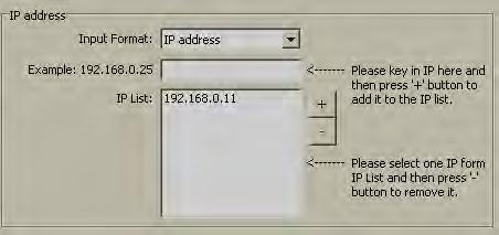
12 Standard Ethernet port (RJ 45 female) shall be available at the Recorder. RS 232/ RS485 shall be supplied as additional options Ethernet Configuration It is possible to use PC software for data logging of Recorders connected on standard Ethernett. Maximum 1024 tags can be configured for data logging, archiving and analysis. The tags cover AI, Math, DI, DO, Counter & Totalizer. 1. Make sure that network adapter in PC is properly configured. IP address, Subnet mask and Gateway should be configured at the PC for using Observer II program. Please contact System administrator to set Unique IP address for the PC. 2. Install Observer II application software in PC. The software may be installed from setup available in the CD supplied as per the order. 3. Ethernet configuration at Recorder Please refer to 4.5 Communication for entering IP address, subnet mask and gateway address manually at the Recorder. Gateway refers to a device on a network that sends local area traffic to other networks. Subnet mask numbers help to define the relationship between host and rest of the network. For every LAN, the Network administrator shall define Subnet mask and Gateway. Obtain subnet mask and gateway address for the LAN at the place where the Recorder to be connected. Enter these details at the Recorder manually using front buttons. 137


13 By default, subnet mask address: By default, Gate way: Allocate the Unique IP address to the Recorder and enter IP address at the Recorder manually. Contact System administrator for obtaining free IP address available at user LAN. Naming duplicate IP address may disable the communication between the Recorder and PC/LAN HUB. 4. Local area network uses UTP cable for Ethernet connectivity. Maximum UTP cable distance between the Recorder and LAN/HUB/PC should be less than 100 Meters. If the distance is more than 100 Meters, additional LAN accessories/equipments may be required for increasing signal strength. Please contact network administrator for more information on extending LAN. 5. Two different types of cables shall be used for connecting the Recorder on Ethernet as follows. For connecting the Recorder to LAN HUB, then standard straight-through Ethernet cable should be used. For connecting the Recorder to PC/Notebook directly, then crossover Ethernet cable should be used. Straight Through Cable VR18-LAN/HUB Crossover Cable VR18-PC/Notebook RJ-45 PIN RJ-45 PIN RJ-45 PIN RJ-45 PIN 1 Tx+ 1 Rc+ 1 Rx+ 3 Tx+ 2 Tx- 2 Rc- 2 Rc- 6 Tx- 3 Rc+ 3 Tx+ 3 Tx+ 1 Rc+ 6 Rc- 6 Tx- 6 Tx- 2 Rc- 138

14 6. Connect proper UTP Ethernet cable as per the requirements and observe the communication status between the Recorder and PC/LAN HUB at the LED s dedicated for the purpose near female RJ 45 connectors. Recorder side Link (Green LED) Green lit: Cable connected between the Recorder and PC/LAN HUB Green Off: No Link between the Recorder and PC/LAN HUB Tx/Rx Orange Lit continuous: No cable connection Orange slow blink: Communication established between Recorder & PC/LAN HUB If the download is sucessful, the User can see the below screen. If Upload is unsuccessful, it shown message as No response from Recorder, connection fails. 139

15 If this is the case, please check the Ethernet cable connections at both the Recorder and PC/LAN HUB side. Also make sure that green communication LED available for proper firm connection at RJ 45 connector. If still communication is not established between the Recorder & PC, then once again check Subnet mask and gateway address at the Recorder & PC. Contact Network/ System administrator for proper Ethernet configuration of the Recorder & PC. Please note that Recorder should have unique IP address in the network and PC being used for Observer II shall have separated Unique IP address in the network. 5.2 Data Acquisition Studio Software Requirements Hardware Recommended hardware PC with 3G GHz processor, 512 MB RAM 50GB free space in the hard disk. Ethernet port, RJ 45 female/ USB port Operating system Windows based Operating systems, Windows XP, Windows 7, Windows 8 etc.. 32 bit and 64 bit operating systems are supported 140
16 5.2.3 Software Software installation 6. Install latest dotnet software from Microsoft website 7. Install Data Acquisition Studio software Historical viewer icon and Real time viewer icon will be created after installation of software, desktop shotcut Historical viewer can be accessed from the following path as well Start-Programs-Historical viewer-historical viewer Real time viewer can be accessed from the following path as well Start-Programs-Data Acquisition StudioStudio- Realtime viewer How to configure Communication Bank It is to set path for the data transfer. It s important to setup Bank properly at the firsthand to proceed further 1. Open existing Project or create a new project from RealTime viewer using one of the following options Start-Programs-Data Acquisition Studio-Realtime Viewer Click on new Project as shown in square icon in the above figure Then the User has give name to the project as shown in the below figure 141


17 Click at bank icon to open communication bank configuration, and select the bank bank accordingly. 142


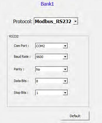
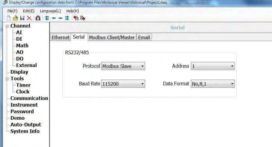
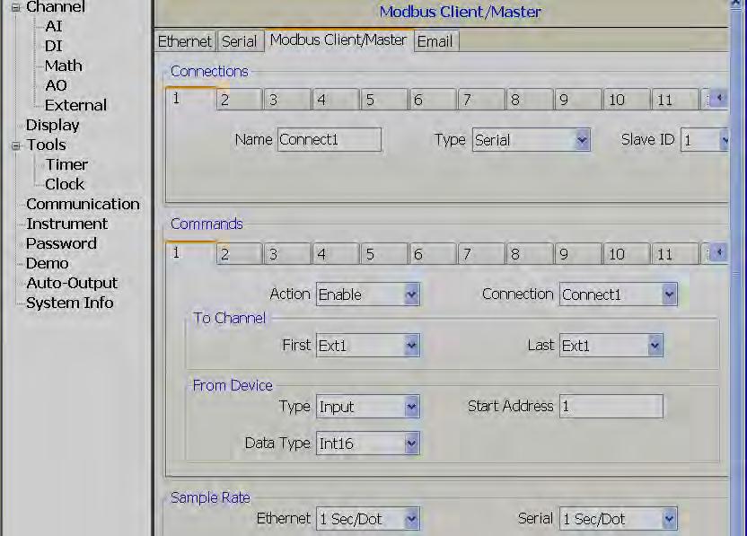
18 If Recorder is connected to Ethernet, then select Modbus_TCP as shown below If Recorder is connected on Serial RS-232 or RS-485, then select Modbus_RS232 as shown below. Please select the com port, baud rate as in the instrument. 143
19 144

20 5.2.5 How to configure Recorder Three ways Touch screen, Software and Storage Media Touch Screen It is possible to configure Recorder directly from Touch screen Press Menu-Config Please refer chapter 4 for more details Ethernet The steps are given below 1. Connect Recorder to PC via cross over or straight Ethernet cable 2. Check IP address of your Computer. Make sure to set IP address of Recorder in same domain as your PC For ex: IP address of your computer: You may set IP address of Recorder as
 and press Enter to change if required Subnet mask: 255.255.255.0 Default Gateway: 192.168.0.1 4. Use Ping from DOS prompt and check communication is ok or not.")
21 3. Procedure to set IP address manually at Recorder Menu-More-Config-Communication, press Enter IP = Select User Define Select, IP address: (Default) and press Enter to change if required Subnet mask: Default Gateway: Use Ping from DOS prompt and check communication is ok or not. If no response, then, check cable or IP address at your computer or IP address at computer 5. Double click at Realtime viewer icon at desktop and follow on screen instructions to create a new project Note: Create a new project only if it s first time. Next time onwards, you can open the saved project available in your computer 146


22 If the connection is working fine, the user can see the below figure. Upon clicking the icon shown you are accepting the configuration 147


23 Click yes to apply the settings. If you have set no password just click ok And after that you can see the below figure 148


24 5.2.8 Removable Media The steps are given below 1. In Recorder, pl. insert empty SD card or USB stick 2. In Recorder, press Menu-More-Config. Press Save Press Yes. It will save Recorder configuration files into USB stick. Check contents of Removable media. It should have following files 3. Remove Removable media from Recorder. Insert in PC 149

25 4. Double click at historical viewer icon at desktop and follow on screen instructions to create a new project Select PR Recorder. Click OK Note: Above screen appears first time if no project files available in Computer Select Storage Media, path to the Recorder files in USB stick or SD card and click OK 150


26 Click Yes. It will open Recorder configuration screen Note: The configuration screen is same as available directly in Recorder. Please refer Chapter 3 & 4 for more details about configuration 5. Do the required changes in the configuration. Click at Send configuration icon 151

27 6. Now, remove Removable media from PC. Insert it into the Recorder. In Recorder, press Menu-More-Config Press Load Press OK 152


28 Press Yes Configuration Please refer Chapter 4 for full details related to configuration Analog Input 153


29 Digital Input Math channel 154


30 Analog Output External Channel 155


31 Display Timer 156

32 Clock Communication 157
33 158
34 Instrument 159
35 160
36 161


37 Password 162

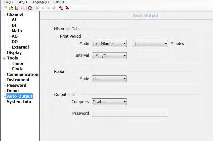
38 Demo Auto-Output 163

39 System Information How to view Historical data Three ways 1. Touch screen 2. Ethernet 3. USB stick Touch Screen Please refer Chapter 3 for details how to view historical data in Recorder directly using the Touch screen Ethernet Note: Please read the following sections first 1. How to configure Communication bank 2. How to configure Recorder - Ethernet Make sure, Project already created and it s saved in Computer, set bank properly to Ethernet before proceeding with the below steps Open Project from Historical viewer using one of the following options 164
40 Desktop: Historical viewer icon Start-Programs-Historical viewer-historical viewer Select Project and click Open Click Import measured data icon Note: Time taken based on amount of data available in internal memory 165
41 Select on any of the trend area, then click at Zoom icon see the historical trend clearly and then Note: Please read Historical viewer help file from software itself for all the features available in Historical viewer software Removable Media Note: Please read the following sections first 1. How to configure Communication bank 2. How to configure Recorder - SD card or USB Make sure, Project already created via SD card or USB, it s saved in Computer, set bank properly to Storage media before proceeding with the below steps Insert Empty - SD card or USB in Recorder Press Menu-More-Dump 166


42 Select All or one of the other available options, then press OK 167


43 Press Yes Now, remove USB stick from Recorder Check contents in the USB stick 168

44 Open Project from Historical viewer using one of the following options Desktop: Historical viewer icon Start-Programs-Historical viewer-historical viewer Select Project and click Open 169


45 Click Import measured data icon Note: Time taken based on amount of data available in internal memory Select Yes if you wish to delete data from USB stick. Select No only if any plans to transfer data say another Computer or if you have any plans to maintain data storage as back up in proprietary format in Computer hard disk 170

46 Select on any of the trend area, then click at Zoom icon see the historical trend clearly and then Note: Please read Historical viewer help file from software itself for all the features available in Historical viewer software How to view Real time data in PC It is possible to monitor Real time data from Paperless Recorder in PC For this, Recorder should be connected to PC via Ethernet or Serial network (RS232/422/485). Set bank properly to proceed with required option 171


47 Bank configuration How to open Real time viewer Two ways Click at desktop icon Start-Programs-Data Acquisition Studio Studio-Real time viewer Click No Click bank icon 172

48 Total 4 communication banks are available Each bank can be configured as Either Modbus Serial (232/422/485) or Modbus_TCP (Ethernet) For ex: If two Paperless Recorders are coming on two different RS485 networks, then, each bank can be configured for each Recorder, provided two COM ports are configured in PC to receive data from two different serial networks. You may use two USB to Serial converters for this application After completing the bank setup, click Save icon main program icon and close return to 173

49 Ethernet 1. Install Data Acquisition Studio software 2. Set bank properly to Ethernet 3. If Recorder connected to PC via Ethernet, make sure Recorder is set with User define IP address and domain same as PC Use Ping instruction from the Dos prompt, make sure Recorder communicating with PC via Ethernet 4. Create a new project in Data Acquisition Studio software and monitor real time data from Recorder directly from PC How to open Real time viewer Two ways Click at desktop icon Start-Programs-Data Acquisition Studio Studio-Real time viewer 174

50 Click Yes 175


51 Click OK Click Save icon and close return to main program icon Note: When real time viewer is running in PC, then, data will be stored in computer hard disk. This data can be archived later from Real time viewer itself from Measured data icon. This data is same as Paperless Recorder internal memory (Historical data) In case if PC running round the clock like a server, then, there may be no need to manually transfer historical data from Recorer to PC via Memory stick. Note: Please read Real time viewer help file from software itself for all the features available in Real time viewer software 176

52 Serial (RS232/422/485) The procedure is similar to Ethernet. But need to set bank properly for Modbus Serial View Real time data from Multiple Recorders Assume, one Recorder database already added in Ethernet, IP address Target: Connect second Recorder, IP address to the Real time viewer Connect both the Recorders and PC to Ethernet switch Use Ping instruction at DOS promot and check communication between PC and two Recorders. If no response, then check IP address at all the devices and also Ethernet cables If there is good response from Recorders from Ping instruction, then, Open Real time viewer Click Configuration data icon Click Add 177


53 Select Device Type = PR Recorder Deselect checkbox at Auto-updae the Tag contents Enter IP address of second Recorder. (Make sure to select user define IP address in Recorder-do not select automation) Click OK Now, second Recorder database will add to Real time viewer. 5.3 Panel Studio version Using this software you can develop custom screens for your display same as SCADA. All the graphics developed on the screens can also be configured for animations. 178

54 Use this editing software to develop animation screens on the Recorder. It is mainly used for application development useful for operator interface in industrial applications. Using Screens, operators will be able to communicate with PLC s, Inverters etc. via COM port and Ethernet port on Modbus RTU or Modbus TCP/IP. Using this software, it is possible to develop operator interface applications like the following. Sending start/stop command from Recorder to PLC to start motors, pumps etc. Display running stats of motors, pumps etc. Display Real time value of process parameters like temperature, flow, pressure etc Visualize process data in meaningful way as bar graphs, dial, meter, level, digital LED etc. Animation like visibility control, blinking, horizontal movement, vertical movement etc System Requirements PC with Minimum 1GHz processor, 1GB RAM (Minimum), 2 GB preferred 500 MB free space in the hard disk Minimum 20% free space in hard disk, Less than 10% space generates error message Ethernet Network adopter RJ 45 female 179
55 RS 232 serial port, RS485/RS232 converter to check online simulation if required USB host to insert USB flash disk Screen resolution better than 1024 X 768 (For Recorder 10 and 1550 projects) Operating system: Windows XP, Windows Vista, Windows 7, Windows 2000 & Windows 2003 Server Software Installation Install Microsoft installer V3.1 Install Microsoft.Net frame work V3.5 SP1 Install Editing Software Install OPC server Install Demo projects Install Historical viewer Install Remote viewer If any folders or files are deleted manually from C:\Program Files\Panel Studio, then, delete a file by name BCFile manually from C:\WINDOWS before attempting to start new installation process. Other wise, you may get error message Access Violation. 180


56 5.3.3 Project status During design time, it is possible to check current status of resources being used Images means symbols used from graphics and symbol factory. These symbols also considered as objects so, if you add symbols, it also updates quantity in objects. For example: If you add 2 symbols and one rectangle object. Then, Images = 2, Objects = 3 181


57 5.3.4 Create new project Open Recorder Editing Software from desktop icon or from Start-Programs- Recorder Editing Software Click on Create a new project 182


58 Project Name: It is Name of Project. For ex: Boiler Location: It is path for project file storage. Default Language: English Width: It is pixels, resolution in dots available on X-axis Height: It is pixels, resolution in dots available on Y-axis Author: Write author name/system integrator name for future reference Version number: It is for version management Comments: It is for project management After entering all the above details, click at OK Menu bar 183

59 5.3.6 File New: To create a new project Open Project: To open existing project Close Project: To close present project Save Project: To save Project in default path Save Project As: To save project in selected path other than default path specified while creating a new project settings. Upload: To upload project from Recorder back to PC Recently: It is to open recently opened projects Exit: To exit from current project Language: To update language files in Recorder. This is required only if new language required at Control Center. Contact factory for further information Clock Synchronization: To Synchronize Recorder clock with PC Clock. 184

60 5.3.7 Environment General: Language: Select Language for project environment. 19 languages are supported from Recorder editing software V1.1 onwards including English, Simplified Chinese, Traditional Chinese, Japanese, French, German, Italian, Polish, Spanish, Portuguese, Brazil Portuguese, Russian, Thai, Czech, Danish, Dutch, Korean, Swedish and Turkish Environment font: Select font required for design time environment. Example: Menu, Tool Box, Project explorer, function editor etc. Project Path: Location to storage of project files Default project path: C:\Program Files\Recorder Editing Software\Recorder Editing Software\PanelProject Graphic Path: Location of default basic Symbols Default graphic path: C:\Program Files\Recorder Editing Software\Recorder Editing Software\Basic Symbols Security: This is to protect opening Recorder editing software in specific Personal computer (Not for project). Once password is entered, it is required to enter password correctly to open Recorder editing software for the current session. This is useful in factory environment to prevent un- authorized users to open Recorder editing software. Note: If you need password for specific project, then, click at Settings in project explorer, select General tab and then enter the Password 185

61 In general, it is preferred to take back up of project files regularly in other standard storage media like CD, DVD etc. It is recommended to store project files in separate folders at D: drive instead of C: drive. Developer may plan hard disk partition and save all project files in drive other than location of operating system such that even if there are problems with Operating system, still it is possible to retrieve project files. Download and Upload: Please refer section Project tools for more detailed information Snap and Grid: It is to define grid behavior in design time environment. Grid: Select this option and select Show grid if grids are to be appeared in screen at design time. Snap lines: Select this option if grids are not required to appear in screen at design time. Snap: Select this option if component coordinates should with in grids all the time. 186


62 Object: Define default font size, Fill color, Back color and Fore color for the properties of most of the objects like label, Check box, Rectangle, Ellipse, Pie, Table, Dial, Level, Meter, Slider, Thermometer etc Edit 187


63 5.3.9 Format Align: It is to align selected components, objects etc. for adjusting their position precisely in screen layout. Available options for selection are Center, Right, Left, Tops, middle & Bottom. Ex: Align two Labels to the left in Recorder screen. Assume both labels are created in Screen1. Select both the labels first using mouse, alternatively, select first label by left click at mouse, then press Ctrl in keyboard and then select second label by left click at mouse. Now, in Menu, click at Format, then select Align, then select Left. Before Align adjustment After Left Align adjustment Make Same Size: It is to adjust different objects to the same Width, Height, Both width and height, Size to grid etc. Ex: Adjust five buttons to same size i.e., height and width. Create five buttons first say in Template. Then, select all these buttons via Mouse and then click at Format, then select Make same size, then select Both Before size adjustment After Same Size adjustment 188


64 Horizontal spacing: It allows adjustment of horizontal spacing between any objects to make Equal/Increase/Decrease/Remove. For ex: There are 3 buttons located at bottom area of a page. Spaces between these buttons are not equal and screen is not looking well. Now, select all the 3 buttons via Mouse or using Ctrl in keyboard along with mouse and then in Menu bar, click at Format, then select Horizontal spacing, then select Make equal. Now, it adjusts space between all these buttons with equal distance. Before Spacing adjustment After Horizontal spacing adjustment Vertical spacing: It allows adjustment of vertical spacing between any objects to make Equal/Increase/Decrease/Remove Before Spacing adjustment After vertical spacing adjustment Center in Page: It allows adjustment of objects center in page horizontally and vertically. For ex: There are 3 buttons located at screen. You wish to locate them center in page horizontally. Then, select these buttons and apply this feature to adjust buttons as per requirement. 189


65 Order: Bring to back: It take object back Bring to Front: It take object to the front side For ex: There is Rectangle box and a label with different colors. If you wish to keep label text on Rectangle, then, for the Rectangle, choose the option, Bring to Back and for the label, choose the option Bring to Front such that both are visible at same time allowing overlapping of two objects for clear display. Lock Controls: It is to lock control for further development. Apply this for a second time to unlock the control View 190

66 Select the required items to view in window layout. Properties If properties is checked as above, then, in the right side bottom of screen layout, properties box will appear showing all the properties for the component/object selected. In above example, rectangle is drawn and once it is selected, then right side bottom corner, it shows all the properties for this specific rectangle if properties are checked in view at Menu bar. It is possible to modify properties of rectangle from property grid. Alternatively, double click on Rectangle and enter the same at Graphical wizard. Output If output is selected in the view, this window appears just below the screen working area. This window will display any errors that appear during compilation of project. In Menu, click at Tools and then Build or alternatively, in standard bar, click at icon to prepare build for the application. Then, project will compile and it shows summary in the output window as shown below. 191


67 Zoom It is to Zoom current screen to various % and it is useful during screen editing particularly if screen size of PC screen is less. If 200% is used and if PC screen size is small, then horizontal and vertical slider will appear automatically in screen to navigate to other areas of screen easily. Full screen It is to display full screen and after selection, screen layout will be as shown below. To go back, in menu, click at View and then Full screen again Reset window layout It is to display default screen layout showing screen working area, tool box, project explorer, output window etc. Ex: If user deselects project explorer at View, then it will not show Project explorer at right side of the window layout. In this case, user may select Project explorer again at View, alternatively, in Menu, click at View and then Reset Window Layout, then it will reset all the view selections and show default window layout Objects 192

68 More details about Basic objects, Enhanced objects, Symbol factory and Graphics are explained in section Tool Box If you would like to increase font size in Menu bar, then, in menu, click at File, then click at Environment and then set font settings. 193

69 Project Above details are explained at section Project Tools Standard bar New Project Open Project Save Project Undo Redo Cut Copy 194
70 Paste Delete Search Show Grid Align to Grid Build Offline Simulator Online Simulator Stop simulation Download Full screen Format bar Bring to Front Bring to Back Lock the control Group Ungroup Align left 195
71 Align center Align right Align Top Align bottom Align middle Make same width Make same height Make same size Size to grid Make horizontal spacing equal Increase horizontal spacing Decrease horizontal spacing Remove horizontal spacing Make vertical spacing equal Increase vertical spacing Decrease vertical spacing Remove vertical spacing Center vertically Center Horizontally Project Explorer 196


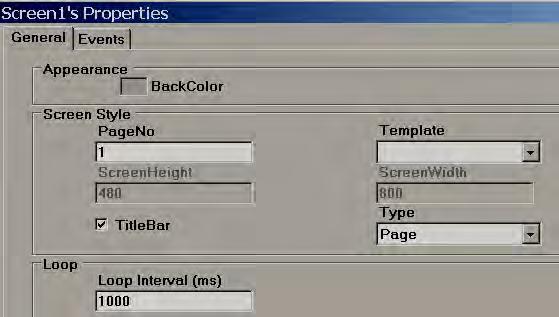
72 Screen This is to add new screen to the project. It is possible to set screen into following type 1. Page When new project is created, screen1 (Page type) is created by default. It is not possible to change screen1 to either template or popup. Screen1 (start page) should be Page type only. How to add a new page In Project explorer, select Screen1, then right click Mouse, then, it shows the screen below. Click at Add, Screen2 will be created and appears as shown below. Now, Select Screen1, and then check its properties. For ex: It is possible to change background color of screen from the page properties Right click mouse keeping pointer on any page, then, you can edit screen properties via wizard. 197

73 198
 defined for screen Properties: Back Color: Define background color of component. Events: Activated: Define tasks to be executed before opening Screen.")
74 It is possible either to open, delete or rename screen. Select screen, then Right click at mouse to appear above dialog. Note: These screen display names are same as available at project explorer. These are different from title bar (Text) defined for screen Properties: Back Color: Define background color of component. Events: Activated: Define tasks to be executed before opening Screen. Deactivated: Define tasks to be executed before closing Screen. Screen Style Page No: Display current page number. Screen Height: Define/Display current screen height. Screen Width: Define/Display current screen width. Template: Select Template page for this screen. Title bar: Control visibility of Title bar and select it in design time. If Title bar = True selected in Page properties, then, number of grids vertically in screen multiplied by grid size will not match with screen height as Title bar occupies some space. Type: Define type of screen. Available options include Template, Page and Popup. 199
 Drag and drop. ii) Select the object say line first and then use mouse to draw a line in screen.")
75 Tool box These can be accessed from menu bar also from objects Basic Objects It is to draw simple shapes in the screen, data entry, data display, alarms view etc. There are three ways to insert above objects into screen. i) Drag and drop. ii) Select the object say line first and then use mouse to draw a line in screen. iii) Select the object say line, then double click (mouse left click) quickly by keeping pointer on selected line. Then, line will appear in screen. For example, select line and Double click it 3 times by keep mouse pointer on line, you can see 3 lines appeared in screen. After inserting object to screen, it is possible to edit properties either by Graphical User Interface (GUI) dialog or editing properties directly in property grid. How to edit via GUI dialog Insert any object in screen. Select the object, right click the mouse and then select properties. Or 200


76 Insert any object in screen. Double click on Object and then GUI dialog will open automatically. How to edit via Property grid By default, property grid will appear at Right-Bottom area of screen editor. If not available, in Menu, click on View and then click at Reset Window Layout, then, property grid will appear at bottom right side of the screen editor just below the Project Explorer. Property grid 201

77 Before placing any objects in screens, check section File- Environment and set default font size, fill color, fore color and back color for the objects as shown Common Properties Appearance Back Color: Set background color of the component. Fore Color: Set Fore color of the component. Bevel: It is to set border including inner border, outer border and style of border. Inner Border: True/False Outer Border: True/False Style: 9 styles are available None, Flat, Single, Double, Raised, Lowered, Double Raised, Double Lowered, Frame Raised, Frame Lowered 202

78 Behavior Visible: True/False, determine whether component/control is visible or hidden Enable: This is for event control. If linked with Digital tag, if tag value =1 in run time, then, events configured for the object will be executed. If tag value = 0, then, events will be not executed Data Tag Binding: Select the Tag of process value Write design time value: If selected, it writes value available at Text in design time and also in run time replacing default value defined at Tag data base. Design Name: It is name of the component. Security level: Define security level for the component. Locked: True/False: It is to Move or Resize the component. Layout Dock: Defines which borders of the control are bound to the container. Location: The coordinates of the upper-left corner of the component relative to upper-left corner of the container. Set X and Y position in screen in pixels. Size: Size of the component in pixel. Set height and width of component in pixels. 203

79 Pointer: It is to deselect the tool selection Line Line: It is an object used to draw line and do animation in Run time linking with Tag. User can edit properties via GUI dialog or property grid as per convenience. After drag/drop of object to screen, double click on object to open GUI dialog or select the object and directly enter properties via property grid available at bottom right corner of screen editor. General Appearance Line Width: Define Line width Direction: Horizontal or Vertical Points Point1: Define X and Y coordinate for line starting point and they show current position. 204

80 Point1: Define X and Y coordinate for line end point and they show current position. Tag Binding Select Tag to be linked with this line. This is useful if animation is required to be done on the line. Animation This is to do animation on line in Run Time Movement time. Select Enable Move check box if movement animation is required in Run Start Position: Define X and Y coordinate for start position when tag value is minimum in Run Time. End Position: Define X and Y coordinate for end position when tag value is max. Run time. Where X position indicates movement from Left side to Right side which is Horizontal movement and Y position indicates movement from Top side to Bottom side which is Vertical movement. 205

81 For ex: Recorder 7 (High Performance) project, 800 X 480 pixels, Normal installation, Horizontal (Left to Right) = 800 pixels, Vertical (Top to Bottom) = 480 pixels Enable move: Selected Start position X = 0, Y = 0 End position X = 800, Y = 0 Tag Value, From = 0, Tag Value To = 100 Now, in Run time, when Tag value = 0, then line will be at Top left and when Tag value = 100, position of line will be Top Right Size Select Enable Size check box to enlarge/decrease size of component in Run time. Start Size: Define X and Y coordinate for start size when tag value is minimum in Run time. End size: Define X and Y coordinate for end size when tag value is max. Run time. Tag Value Select Tag to be linked with this line. This is useful if animation is required to be done on the line. Bands This is to select various bands as pert of animation in Run Time 206


82 Band Count Maximum 32 bands are available. For ex: In above sample, If Tag value is between 0 to 20, line will be in Yellow color If Tag value is 21 to 80, then, line color = Green If Tag value in Run time is above 80, line color = RED Polygon Polygon: It is to draw a polygon. After finishing drawing, double click using mouse (left) to complete the Polygon. It is also possible to link polygon to a tag and define user friendly animation to appear in Run time. 207

83 Animation This is to do animation on Polygon in Run Time Fill Select Enable Fill if filling animation is required on Polygon object in Run time. When tag value changes in Run time, it appears filling with defined color inside Polygon object. It is like a bar graph but filling is with in polygon shape defined during design time. Start Fill: Define Start value for Fill End Fill: Define End value for Fill Movement It is to define movement position and it is the same as explained for Line object.earlier. Size It is to define Size enlarge/decrease and it is the same as explained for Line object earlier. Tag Value 208

84 Select Tag to be linked with Polygon object. This is useful if animation is required to be done on the Polygon. Band editor: Maximum 32 bands are available. For example: In above sample, If Tag value is between 0 to 20, Polygon fill color = Yellow If Tag value is 21 to 80, then, Polygon fill color = Green If Tag value in Run time is above 80, Polygon fill color = RED If required, it is also possible to configure blink property and set blink color in any band. 209

85 Rectangle Rectangle: It is to draw a Rectangle and do animation in Run time linking with Tag. 210

86 Animation Supported: Fill, Movement and Size The above features are same as explained for Line and Polygon objects 211

87 Band editor: Maximum 32 bands are available. For ex: In above sample, If Tag value is between 0 to 20, Rectangle fill color = Yellow If Tag value is 21 to 80, then, Rectangle fill color = Green If Tag value in Run time is above 80, Rectangle fill color = RED If required, it is also possible to configure blink property and set blink color in any band. 212


88 Ellipse Ellipse: It is to draw Ellipse or a circle and do animation in Run time linking with a Tag. 213

89 Animation Supported: Fill, Movement and Size The above features are the same as explained for Line and Polygon objects. Band editor: Maximum 32 bands are available. For example: In above sample, If Tag value is between 0 to 20, Ellipse fill color = Yellow If Tag value is 21 to 80, then, Ellipse fill color = Green If Tag value in Run time is above 80, Ellipse fill color = RED 214

90 If required, it is also possible to configure blink property and set blink color in any band, Arc Arc: It is to draw Arc and do animation in Run time linking with Tag. Start Angle: Define start angle, Sweep angle: Define end angle 215


91 Supported Animation: Movement and Size Band editor: Maximum 32 bands are available. Band editor for Arc is the same as explained for Line object earlier. 216
 for displaying process values to appear like a tabular column. User can edit properties via GUI dialog or Property grid as per convenience.")

92 Table It is to draw a table in design time by specifying number of rows & columns. All rows/columns will have the equal width and height. It is possible to place labels on rows (Linked with Tags) for displaying process values to appear like a tabular column. User can edit properties via GUI dialog or Property grid as per convenience. After drag/drop of the object to screen, double click on object to open GUI dialog. While working with Table, in page properties, select Snap to Grid = False such that it is easy to place labels/ Textbox in required position easily. Drag/Drop Table from Basic objects to screen and double click on Table. Following screen will open. Note: Deselect Same Width to adjust column width in the Table Note: Deselect Same Height to adjust Row height in the Table 217


93 Property grid Properties Back Color: It is back color for the table Fore Color: It is color for the lines in table Line Width: It is the width of lines Columns: It is to define number of columns in table Rows: It is to define number of rows in table Name: It is the unique name for the table in specific page Locked: It is to determine if table is locked for further moving and resize in design time and you can set this in property grid Numeric Up/Down Numeric Up/Down is Graphical User Interface widgets that allow the user to increase or decrease value of a tag by pressing Up or Down arrows in Run time or alternatively enter numeric value directly via keypad. User can edit properties via GUI dialog or Property grid as per convenience. After drag/drop of object to screen, double click on the object to open GUI dialog. Every Numeric Up/Down button should be linked with an Analog Tag. Except Up/Down arrow, if user presses another area of Numeric Up/Down component in Recorder at Run time, Numeric keypad will open. Then, user can enter numeric value directly. Numeric Keypad will not appear in PC during Online/Offline simulation and you can use keyboard directly to enter numeric value. 218

94 Increment: Select the value to be incremented/ decremented each time when up/down arrow is pressed in Run time. Properties Write design time value: If selected, it writes value available at Text in design time and also in run time replacing default value defined at Tag data base. Rounding: Rounding to nearest value Decimal: Enter number of decimal points Value: Current Tag value. It is used to enter value in design time and check how value is displayed in Run time. Increment: Value to be incremented in Run time after pressing Up/Down button. 219

95 Minimum: Define Minimum value Maximum: Define Maximum value Soft keyboard: If enabled, then, it is possible to control the keypad appearance in run time. For example, if alignment is selected as Middle center, then, when keypad appears in run time, it will be located to Middle center in screen Events: Define events to be executed when operator pressed on Up/Down arrow and value changes occurs in Run time. 220


96 Digital LED It is to view process value in Digital format. Generally it is linked with Analog type tag (Analog input type tag at PLC, which is received as 4-20 ma signals from field transmitters like Temperature, Pressure, Flow, Level, Position etc...) For common properties like Back Color, Bevel, please refer section Common Properties 221

97 Property grid Properties Back Color: Define background color for the component Inner border: Select if inner border is required for the component Outer border: Select if outer border is required for the component Style: Define border style. Available options are Single, Double, Raised, Lowered, Double Raised, Double Lowered, Frame Raised and Frame Lowered Active Color: Define Active Color of Segment for Digits Inactive Color: Define color of inactive segment. In the seven-segment LED display, some segments might be active and some other segments might be inactive depending numeric value. Digit Height: Define Height of Digits Digit Width: Define width of Digits Digit Space: Define Space between digits Segment Space: Define space between segment to segment for digits Segment Thickness: Define thickness of segments for digits Decimals: Define number of decimal points Tag Binding: Select the Analog Tag of process value 222

98 Digital Box Digital Box is a Graphical User Interface widget that displays Digital Tag value along with four predefined labels as attributes for the process value in Run time. Every Digital Box normally used with Analog Tag to display process values like Temperature, Pressure, Flow etc., It also allows 4 different labels as attributes for displaying tag related information. 223


99 Properties Attribute1: attribute to be displayed at Top left side of Digital Box Attribute2: attribute to be displayed at Top Right side of Digital Box Attribute3: attribute to be displayed at Bottom Left side of Digital Box Attribute4: attribute to be displayed at Bottom Right side of Digital Box Attribute font: Define font for attribute, select type of windows font, size of font and style of font which includes Regular, Bold, Italic, Underline, and Strike out. Back color: Define back ground color Fore Color: Define fore color for the font Decimal: Define number of decimal places for the value to be displayed Value font: It is to adjust size of display process value font, select type of font, size of font and style of font including Regular, Bold, Italic, Underline and Strike out Text box It is to Read/Write, Alpha numeric text in Run time. It can be linked with any type of tag. If object is linked with String type tag, then, Alpha numeric keypad opens in Run time if users touch on object. If object is linked with Analog or Digital tag, then, numeric keypad opens in Run time if user attempts to touch on object. If Digital tag is used, then, make sure decimals are set to


100 Alpha numeric keypad Numeric keypad 225

101 Note: For common properties of all the components, please check beginning of this section. Write design time value: If selected, it writes value available at Text in design time and also in run time replacing default value defined at Tag data base. Soft keyboard: If enabled, then, it is possible to control the keypad appearance in run time. For example, if alignment is selected as Middle center, then, when keypad appears in run time, it will be located to Middle center in screen 226


102 Label Label is to write a simple text for user information in the screen to improve clarity for the operator. Example: Tag name, Pump number display etc. It is also used to display process value (read only) to operators by linking with Tag. 227


103 Note: For common properties of all the components, please check beginning of this section. Properties Text: Define text associated with this component and it should be entered at design time only. Text Align: It is for Alignment of text and available options include Top Left, Top Center, Top Right, Middle Left, Middle Center, Middle Right, Bottom Left, Bottom Center and Bottom Right Text Font: Define font for text including type of font, size of font and style of font. Styles include Regular, Bold, Italic, Underline and Strikeout. Tag Binding: Select the Analog Tag of process value Decimal: Define number of decimal points 228

104 Date and time Label It is to display Date and Time in screen. If date and time required in more than one screen, it is better to create screen and select screen type as Template and then link this template to all other required screens to display Date and Time automatically. This is more efficient than keeping Date and Time label in more than one screen Button A Button is commonly used to perform an action after operator presses it via finger or by clicking using a mouse in Run time. Generally button is used to turn ON a bit, Turn OFF a bit etc. used with Digital type tags. Example: Start Pump, Stop pump etc. Three kinds of events supported for a button. Clicked, Pressed and Released. Several functions are supported which can be configured from Events and all the functions are covered in next section Function editor. 229


105 Properties Back Color: Selects Back color for the object. Also, it is possible to select transparent mode if required from V1.20 onwards 230


106 Text: Define required text to be displayed on the object. It is also possible to enter multiline text from V1.20 onwards Show select: True/False. If it is selected, then, when operator presses this button, it will show dotted line just inside the button. When operator presses another button, it automatically shows selected show status to latest button and deselect select status for previous button pressed by the operator. Border Style: Define border style. Available options include none, fixed single and fixed 3D Image: Select the Image to be displayed on top of the object. Image can be selected either from Basic symbols or Symbol factory or custom image in formats of bmp, wmf, jpg, gif and png Text font: Define the font including name of font, size of font and style of font 231


107 Timing: This is an advanced feature and used to make sure operator action is properly received by PLC when PLC scan time is large. Hold time: This is generally applicable for Click event. This keep on executing action defined at Clicked event for the time defined at hold time. We suggest using holding time of button more than PLC scan time. Example: 300 msec. Example: Push button Function Example: Operator presses button for only 200 msec. When operator clicks button, Tag1 = 1 and when operator releases button, Tag1 = 0, holding time = 1000 msec. 232


108 Since holding time is set for clicked action, released action, TurnBitOff will be executed only after completing 1000 msec but not immediately after operator releases the button. In this case, if PLC scan time is 800 msec, and still operator click action will be detected properly because operator command will be available for 1000 msec. Auto Repeat & Interval time: This is generally applicable for Pressed event. It is to repeat the action defined at Pressed event as per set interval time. Example: When operator keeps pressing button, set point should be incremented by 1 for every 1 sec and Tag1 is Integer type. Auto repeat with time interval and holding time cannot be used together. Tag binding: Select the tag that should be linked with the button to show different display in run time based on configuration available at Band editor. Both Analog 233


109 If Tag1 is Analog Type (32 bit), it is also possible to show different display based on individual bits. By default, it is disabled. You can select the bit from the combo box and then configure band editor as per project requirements. Bands: Define bands for the button. Back color: Define back color for the selected band Fore color: Define fore color to appear for selected band in run time Text: Define the text to be displayed for selected band in run time Visible: Control the visibility Blink: Select if blink is required when tag value reaches selected band in run time. If yes is selected, then, it allows to enter blink color as well. Bitmap file: Select the image to be displayed on button when tag value reaches this band in run time. 234

110 For example: When Tag1=0, show Red color motor symbol on button. When Tag1=1, show Green color motor symbol on button. Note: Two different symbols are required for the above Bmp, wmf, jpg, gif and png types are supported. If selected file is other than wmf, then, it is also possible to select Image layout and transparent options. From File browser: It is to select image from required location From Basic Symbol: It is to select images from free basic symbols (*.wmf format) available in Recorder editing software. From symbol factory: It allows to select symbol from symbol factory in wmf format Image layout: None, center and Stretch options are available. Stretch means, selected bitmap will be fixed to the size of the button. Note: If bitmap is with poor resolution, when stretch is used, it may show low quality image in screen. Flip: It is to flip button and needs to be configured at design time. Available options include None, Horizontal, Vertical and Both. Rotation: It is to rotate button in predefined angles and need to be configured at design time. Available options include 0 O, 90 O, 180 O and 270 O Value: Define maximum range of selected band. Low range will be value defined at previous band. There is no need to enter any value for band 1 as its value is 0 which is low range. 235

111 If button is linked with Digital Tag, then, in the band editor, it shows only two bands for value 0 and 1. When, button is linked with Analog tag, it is possible to configure up to 32 bands for showing different states of button based on value of tag and then, it shows status similar to word lamp. Security control: Define security level for button. It allows user to operate the button only when operator security level is equal to or more than security level defined here. Please refer section Security at Project explorer for more information about security features. Events Clicked: Define the action when user presses button in Run time. If required, it is possible to configure holding time for this action. Holding time is a very useful function. If PLC has a large scan time, some times, operator click action will be not detected by the PLC. In this case, it is possible to have a hold time for click event such that operator 236

112 action will be continuously present for time defined at holding, such that PLC will receive operator action properly. Practically once operator touches button and releases finger instantly, it is called as a Clicked action. During this time, a total of three actions will be executed. Click, Pressed and Released Case-1 Holding time = 0 In above example, Tag1 value becomes 3 Case-2 Holding time = 5000 m sec In above example, if scan time for Tag1 is 1000 m sec, then, Tag1 value becomes approximately 8. When, button is clicked, Clicked and Pressed event action occurs and Tag1 value becomes2. Since holding time is 5 sec, for next 5 seconds, Tag1 value is incremented by 1 for each 1 sec, so, it Tag1 value becomes 7. When button is released, Tag1 value incremented by 1 again, so it becomes 8. The above example is for illustration only to understand about events for button object. Pressed: Define the action when user continuously presses on button. If required, it is possible to configure Auto repeat and interval time for this action. 237


113 Practically once operator touch button, clicked event will be executed first and when operator keep pressing button continuously, then, pressed action will keep on being executed. When operator releases the finger on button, released action will be executed. Auto repeat: On, Time interval=1000 m sec. In this case, Tag1 value first increment by 1, then, keep on incrementing by 1 once in 1000 m sec. as long as operator presses the button and increment by 1 when operator releases the button. Released: Define the action when user release press on button Switch Function In this case, it requires using two buttons. One button to turn ON Tag and another button to turn OFF Tag When operator clicks Button1, Tag1 = 1. Now, Tag1 = 1 even after operator releases button and it continues to maintain earlier state. When operator clicks Button2, Tag1 = Function editor This is very useful to select different functions to execute based on operator action. in Run time and this provides an easy way for application developer to use a ready made macro instead of writing scripts. Insert Button in any screen and configure events. The following functions are supported. 238


114 Page Control functions Every screen has a screen number and pointer will be screen number for navigation in. GotoFirstPage: It is to navigate from current screen to first screen GotoPreviousPage: It is to navigate from current screen to previous screen GotoNextPage: It is to navigate from current screen to next screen GotoLastPage: It is to navigate from current screen to Last screen GotoPage: It is to navigate from current screen to specific screen by name GotoPageByNumber: It is to navigate from current screen to specific page by number GotoPopUp: It is to open specific pop up screen by name ClosePopUp: It is to close pop up screen by name 239


115 Tag functions SetValuetoTag: It writes value to a tag Example: Set 90 to TagA when operator presses on a button in run time AddValuetoTag: It is add value to Tag SubtractValuefromTag: It is to subtract value from Tag CopyTagBtoTagA: It is to copy TagB value to TagA AddTagBtoTagA: It is to add TagB to TagA and store result in TagA 240


116 SubtractTagBfromTagA It is to subtract TagB from TagA and store result in TagA SwapTagAforTagB It is to swap TagB and TagA CopyStringTagBtoTagA It is to copy string type TagB to TagA SetStringtoTag: It is to write string to String type Tag CopyBlockfrom TagBtoTagA: It is to copy block of tags from TagB to Tag1 For example: Copy 4 contineous tags from Tag5 to target location starting from Tag1. Now, Tag5 is copied to Tag1, Tag6 is copies to Tag2 and so on. Note: Maximum block size is limited to 80 tags EditValuetoTag: It is to edit tag value in run time from keypad. For example, if this function is called from button click event, then, keypad will open in run time and user can enter set point TurnBitOn: It is to turn on bit. If momentary Turn on is required, then in Click action, select Turn On, then, in Released action, select Turn OFF TurnBitOFF: It is to turn off bit 241


117 Togglebit: It is to toggle the bit Fig: Ladder logic in PLC 242


118 Fig: On button configuration If button is not switching properly at PLC, then, in General Tab, select Hold check box and enter the hold time. Default value is 50 msec. If required, adjust this to 100 msec. and check again. 243


119 Fig: Off Button configuration If button is not switching properly at PLC, then, in General Tab, select Hold check box and enter the hold time. Default value is 50 msec. If required, adjust this to 100 msec. and check again. 244

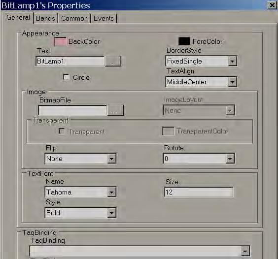
120 Fig: Bit lamp status Bit lamp It is used to show Digital input status for operator. It is linked with either Digital input type tag or Analog input type tag. By using band editor, it is possible to display different foreground color, different background color, different text, different symbols, different Blink color, and control visibility when Tag value is 0 or 1. When Bit lamp is linked with Digital type Tag, it has only two bands, by default, Band1 value is 0 and Band 2 value is 1. For example: If Tag1 = 0, show Red color back ground with Orchid color blink. If Tag9=1, show green color back ground. GUI Wizard 245
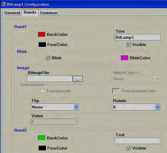
121 246

122 Bitmap file: Select the image to be displayed when tag value reaches this band in run time. For example: When Tag1=0, show Red color motor symbol When Tag1=1, show Green color motor symbol Note: Two different symbols are required for the above Bmp, wmf, jpg, gif and png types are supported. If selected file is other than wmf, then, it is also possible to select Image layout and transparent options. From File browser: Allows to select images in formats of bmp, wmf, jpg, gif and png From Basic Symbol: Allows to select wmf format images from basic symbols From symbol factory: It allows selecting symbol from symbol factory in wmf format Image layout: None, center and Stretch options are available. Stretch means, selected bitmap will be fixed to the size of the bit lamp Note: If bitmap is with poor resolution, when stretch is used, it may show low quality image in screen. Flip: It is to flip bit lamp and needs to be configured at design time. Available options include None, Horizontal, Vertical and Both. Rotation: It is to rotate bit lamp in predefined angles and need to be configured at design time. Available options include 0 O, 90 O, 180 O and 270 O 247

123 Circle: By default, bit lamp object shape is in Rectangle. Select this if you wish to change shape to circle. It is more useful to show status of digital inputs for the operator in Run time How to show status of individual bit in Analog type tag Some times, you will get 16 bit/32 bit tag from PLC with different diagnostic information and you would like to show 16 bit/32 bit lamps in Recorder screen. When Bit lamp is linked with Analog tag example: Int16/Int32, then also it has two bands, by default, Band1 value is 0 and Band 2 value is 1. In this case, using each bit lamp, it is possible to show status of each individual bit status with in 32 bits as per configuration available at band editor. In above fig, Tag2 is analog type (4 byte), so, TagBitNo combo box will appear for selection of required bit with in 32 bits (0 to 31). If Tag2 is Digital type tag, then, TagBitNo. Combo box is not visible Word lamp It is similar to Bit lamp but linked with Analog type tag only. It can have many bands. By using band editor, it is possible to display different foreground color, different background color, different text, different symbols, different Blink color, and control visibility when Tag value change values in Run Time. For example: Tank Level indicator When Tag1 value is 0 to 10, Text = Low Low Level, Color = Yellow Blinking 11 to 20, Text = Low Level, Color = Yellow Background 21 to 80, Text = Normal, Color = Green back ground 81 to 90, Text = High level, Color = Red back ground 91 to 100, Text = High High Level, Color = Red blinking Create 5 bands as shown 248


124 GUI Wizard/Dialog Band1 range = 0 to value defined at band


125 i.e., 0 to 10 Band2 range: Band 2 value to Band3 value-1 i.e., 11 to 20 Band3 range: Band 3 value to Band4 value-1 i.e., 21 to
OPERATION MANUAL. MV-410HS Layout Editor. Version higher. Command
 OPERATION MANUAL MV-410HS Layout Editor Version 3.0 - higher Command Command Table of Contents 1. Setup... 1 1-1. Overview... 1 1-2. System Requirements... 1 1-3. Operation Flow... 1 1-4. Installing MV-410HS
FactoryLink 7. Version 7.0. Client Builder Reference Manual
 FactoryLink 7 Version 7.0 Client Builder Reference Manual Copyright 2000 United States Data Corporation. All rights reserved. NOTICE: The information contained in this document (and other media provided
Instrumentation PPS Series Videographic Data Recorders. PPS Series Videographic Data Recorders. Now with Touch Screen Technology!
 Now with Touch Screen Technology! PPS-1000 PPS-2000 PPS-3000 Product Overview The PPS Series is a major advance in the market for Paperless Videographic Data Recorders incorporating Touch Screen Technology
CENTAUR S REAL-TIME GRAPHIC INTERFACE V4.0 OPERATOR S MANUAL
 CENTAUR S REAL-TIME GRAPHIC INTERFACE V4.0 OPERATOR S MANUAL TABLE OF CONTENTS Installation... 6 Introduction to Centaur s real-time Graphic Interface... 6 Computer Requirements... 7 Operating System
PR Series Paperless Recorders
 PR Series Paperless Recorders Head Office: Brainchild Electronic Co., Ltd. 209 Chongyang Road, Nangang Dist., Taipei 11573, Taiwan Tel: +886-2-2786-1299 Fax: +886-2-2786-1395 Website: www.brainchild.com.tw
ezimagex2 User s Guide Version 1.0
 ezimagex2 User s Guide Version 1.0 Copyright and Trademark Information The products described in this document are copyrighted works of AVEN, Inc. 2015 AVEN, Inc. 4595 Platt Rd Ann Arbor, MI 48108 All
User Manual Version 1.1 January 2015
 User Manual Version 1.1 January 2015 - 2 / 112 - V1.1 Variegator... 7 Variegator Features... 7 1. Variable elements... 7 2. Static elements... 7 3. Element Manipulation... 7 4. Document Formats... 7 5.
Libraries. Multi-Touch. Aero Peek. Sema Foundation 10 Classes 2 nd Exam Review ICT Department 5/22/ Lesson - 15
 10 Classes 2 nd Exam Review Lesson - 15 Introduction Windows 7, previous version of the latest version (Windows 8.1) of Microsoft Windows, was produced for use on personal computers, including home and
KODAK Software User s Guide
 KODAK Create@Home Software User s Guide Table of Contents 1 Welcome to KODAK Create@Home Software Features... 1-1 Supported File Formats... 1-1 System Requirements... 1-1 Software Updates...1-2 Automatic
Label Design Program Label Artist-II Manual Rev. 1.01
 Label Design Program Label Artist-II Manual Rev. 1.01 http://www.bixolon.com Contents 1. Introduction... 2 2. Supported Operating Systems... 2 3. Features... 3 3-1 Menu... 3 3-1-1 New... 3 3-1-2
TPEditor User Manual
 Table of Contents TPEditor User Manual Chapter 1 TPEditor Operation... 1-1 1-1 Recommended System Requirements... 1-1 1-2 TPEditor Software Installation... 1-1 1-3 Basic Introduction... 1-6 1-4 Skills
CONTASign Pro User Manual
 CONTASign Pro User Manual CONTASign PRO MANUAL v3.5 rev01 Page 1 of 51 CONTA-CLIP Contents Page No. 1. Main Window Layout 4 - Window Layout Customisation 5 - Window Configuration 6 2. Start Menu & Quick
MagicInfo VideoWall Author
 MagicInfo VideoWall Author MagicInfo VideoWall Author User Guide MagicInfo VideoWall Author is a program designed to construct a VideoWall layout and create VideoWall content by adding various elements
Designer Reference 1
 Designer Reference 1 Table of Contents USE OF THE DESIGNER...4 KEYBOARD SHORTCUTS...5 Shortcuts...5 Keyboard Hints...5 MENUS...7 File Menu...7 Edit Menu...8 Favorites Menu...9 Document Menu...10 Item Menu...12
Operating Instructions WhiteBoard Software for Mac 1.4
 Operating Instructions WhiteBoard Software for Mac 1.4 Please read these instructions carefully before using this product, and save this manual for future use. Panasonic Corporation 2018 Contents INTRODUCTION...
NiceLabel Designer Standard User Guide
 NiceLabel Designer Standard User Guide English Edition Rev-1112 2012 Euro Plus d.o.o. All rights reserved. Euro Plus d.o.o. Poslovna cona A 2 SI-4208 Šenčur, Slovenia tel.: +386 4 280 50 00 fax: +386 4
QLabel-IV Operation Manual
 P/N. 920-0060611-02 Edition C 07.2009 QLabel-IV Operation Manual QLABEL-Ⅳ... 3 PART I: ABOUT QLABEL-Ⅳ...3 1: INTRODUCTION... 3 2: INSTALLATION... 3 PART II: STARTING ON QLABEL-IV...6 3: START QLABEL-Ⅳ...
Navigator Software User s Manual. User Manual. Navigator Software. Monarch Instrument Rev 0.98 May Page 1 of 17
 User Manual Navigator Software Monarch Instrument Rev 0.98 May 2006 Page 1 of 17 Contents 1. NAVIGATOR SOFTWARE 2. INSTALLATION 3. USING NAVIGATOR SOFTWARE 3.1 STARTING THE PROGRAM 3.2 SYSTEM SET UP 3.3
MELBOURNE LED LEDEDITOR 2016 SOFTWARE MANUAL
 MELBOURNE LED LEDEDITOR 2016 SOFTWARE MANUAL Chapter 1: Introduction 1.1 Function Feature The LED Editor Version 2 has been upgraded to offer wider range of control and satisfy requirement of multi functions
ASIC-200 Version 5.0. integrated industrial control software. HMI Guide
 ASIC-200 Version 5.0 integrated industrial control software HMI Guide Revision Description Date C Name change, correct where applicable with document 4/07 HMI Guide: 139168(C) Published by: Pro-face 750
How to...create a Video VBOX Gauge in Inkscape. So you want to create your own gauge? How about a transparent background for those text elements?
 BASIC GAUGE CREATION The Video VBox setup software is capable of using many different image formats for gauge backgrounds, static images, or logos, including Bitmaps, JPEGs, or PNG s. When the software
LED STUDIO USER MANUAL
 BLAIR COMPANIES LED STUDIO USER MANUAL Part # 33-19-14 5107 Kissell Avenue Altoona PA 16601 814-949-8287 blaircompanies.com TABLE OF CONTENTS Chapter 1 Introduction... 1 Chapter 2 Install and Uninstall...
Distributors News. December, 2004 Unitronics has announced a major market release. The release includes:
 MAJOR RELEASE VISILOGIC 4.00, VISION 290, REMOTE ACCESS 4.00 & DATAXPORT 2.00 Unitronics has announced a major market release. The release includes: PID: includes internal Auto-tune Trends: Real-Time HMI
SPARK. User Manual Ver ITLAQ Technologies
 SPARK Forms Builder for Office 365 User Manual Ver. 3.5.50.102 0 ITLAQ Technologies www.itlaq.com Table of Contents 1 The Form Designer Workspace... 3 1.1 Form Toolbox... 3 1.1.1 Hiding/ Unhiding/ Minimizing
Exhibitor Software User s Manual. Exhibitor Software V
 Exhibitor Software User s Manual Exhibitor Software V1.0.1 090908 1 Contents 1. Exhibitor Software 2. Installation 3. Using Exhibitor Program 3.1 Starting the Program 3.2 Logging in to the Program 3.3
Quick Start Guide (V1.03) UD.6L0201B1064A01
 UD.6L0201B1064A01") ivms-4200 PCNVR Quick Start Guide (V1.03) UD.6L0201B1064A01 Thank you for purchasing our product. If there is any question or request, please do not hesitate to contact the dealer. This manual applies
ivms-4200 PCNVR Quick Start Guide (V1.03) UD.6L0201B1064A01 Thank you for purchasing our product. If there is any question or request, please do not hesitate to contact the dealer. This manual applies
W-E
 Signage Suite V2.20 User Guide 605220-02-01-W-E-051613-02 Trademarks Windows XP, Windows Vista, Windows 7, and Microsoft are registered trademarks of Microsoft Corporation. All other trademarks are the
StickFont Editor v1.01 User Manual. Copyright 2012 NCPlot Software LLC
 StickFont Editor v1.01 User Manual Copyright 2012 NCPlot Software LLC StickFont Editor Manual Table of Contents Welcome... 1 Registering StickFont Editor... 3 Getting Started... 5 Getting Started...
IS2000. Administrative Operator s Guide
 IS2000 Administrative Operator s Guide Table of Contents Logging Off... 7 Event Manager... 7 HARDWARE MANAGER... 8 Maneuvering the Hardware Tree... 8 Unlocking the Module... 8 Viewing the Hardware Tree...
LABEL MATRIX TEKLYNX V E R S I O N 8 Q U I C K S T A R T G U I D E
 TEKLYNX LABEL MATRIX V E R S I O N 8 Q U I C K S T A R T G U I D E Note Quick Start Guide The information in this manual is not binding and may be modified without prior notice. Supply of the software
Phone: Fax: Web: -
 Table of Contents How to Use GTWIN 1. Functions of Parts...1-1 1.1 Screen Names of GTWIN... 1-2 1.2 Menu Bar... 1-3 1.3 Toolbar... 1-4 1.4 Screen Manager... 1-6 1.5 Parts Library... 1-7 1.6 Graphicbar...
SOFTWARE INSTRUCTIONS DIGITAL SPEAKER PROCESSOR DP-SP3
 SOFTWARE INSTRUCTIONS DIGITAL SPEAKER PROCESSOR DP-SP3 Thank you for purchasing TOA s Digital Speaker Processor. Please carefully follow the instructions in this manual to ensure long, trouble-free use
Using SymPrint to Make Overlays, Templates & More...
 Welcome to SymPrint SymPrint is an easy-to-use tool for creating communication overlays, worksheets, classroom activities and more using a modern toolbar and common-sense interface modeled after the programs
User Manual. MPPTracker. Management Software for Solar Charge Controller. Version: 1.2
 User Manual MPPTracker Management Software for Solar Charge Controller Version: 1.2 Table of Contents 1. MPPTracker Overview... 1 1.1. Introduction... 1 1.2. Features... 1 2. MPPTracker Install and Uninstall...
Motic Images Plus 3.0 ML Software. Windows OS User Manual
 Motic Images Plus 3.0 ML Software Windows OS User Manual Motic Images Plus 3.0 ML Software Windows OS User Manual CONTENTS (Linked) Introduction 05 Menus and tools 05 File 06 New 06 Open 07 Save 07 Save
WinCC V4. Manual Part 2/3 C79000-G8276-C107-01
 WinCC V4 Manual Part 2/3 Edition August 1997 WinCC, SIMATIC, SINEC, STEP are Siemens registered trademarks. All other product and system names in this manual are (registered) trademarks of their respective
MIMAKI ENGINEERING CO., LTD.
 For Windows XP/Windows 2000 Cutting Application Software SimpleCut Operation Manual MIMAKI ENGINEERING CO., LTD. D201463 Contents Introduction 1 About this Manual 2 Chapter 1 Installation Procedure 3
Code Finix Label Designer V 1.0 User Guide
 Code Finix Label Designer V 1.0 User Guide Introduction Welcome, Code Finix Label Designer is a family of professional labeling software products that brings a complete barcode printing solution for desktop
KODAK Software User s Guide. Software Version 9.0
 KODAK Create@Home Software User s Guide Software Version 9.0 Table of Contents 1 Welcome to KODAK Create@Home Software Features... 1-1 Supported File Formats... 1-1 System Requirements... 1-1 Software
IGSS 13 Configuration Workshop - Exercises
 IGSS 13 Configuration Workshop - Exercises Contents IGSS 13 Configuration Workshop - Exercises... 1 Exercise 1: Working as an Operator in IGSS... 2 Exercise 2: Creating a new IGSS Project... 28 Exercise
Table of Contents. Logos Imaging Application User s Manual Version Page 1
 Table of Contents About... 4 System Requirements... 5 Uninstall Previous Versions... 5 Install LIA 6.0... 6 Install the Device Drivers... 13 Register... 14 Getting Help... 14 Technical Support... 14 Workspace
L E S S O N 2 Background
 Flight, Naperville Central High School, Naperville, Ill. No hard hat needed in the InDesign work area Once you learn the concepts of good page design, and you learn how to use InDesign, you are limited
ECDL Module 6 REFERENCE MANUAL
 ECDL Module 6 REFERENCE MANUAL Presentation Microsoft PowerPoint XP Edition for ECDL Syllabus Four PAGE 2 - ECDL MODULE 6 (USING POWERPOINT XP) - MANUAL 6.1 GETTING STARTED... 4 6.1.1 FIRST STEPS WITH
Edupen Pro User Manual
 Edupen Pro User Manual (software for interactive LCD/LED displays and monitors) Ver. 3 www.ahatouch.com Some services in Edupen Pro require dual touch capability. In order to use dual touch, your computer
Aurora Multi-image System Control Software. User Manual
 Aurora Multi-image System Control Software User Manual Product Information Model: Aurora Controller Software Version: V010200 Release Date: January 18th, 2017 Company OSEE TECHNOLOGY CO., LTD. Contact
End User Guide. 2.1 Getting Started Toolbar Right-click Contextual Menu Navigation Panels... 2
 TABLE OF CONTENTS 1 OVERVIEW...1 2 WEB VIEWER DEMO ON DESKTOP...1 2.1 Getting Started... 1 2.1.1 Toolbar... 1 2.1.2 Right-click Contextual Menu... 2 2.1.3 Navigation Panels... 2 2.1.4 Floating Toolbar...
Press the Plus + key to zoom in. Press the Minus - key to zoom out. Scroll the mouse wheel away from you to zoom in; towards you to zoom out.
 Navigate Around the Map Interactive maps provide many choices for displaying information, searching for more details, and moving around the map. Most navigation uses the mouse, but at times you may also
REPORT DESIGNER GUIDE
 REPORT DESIGNER GUIDE 2017 Advance BIM Designers Report Designer Guide This document has been very carefully prepared in the hope to meet your expectations and to answer all your questions regarding
User Manual WatchPower
 User Manual WatchPower Management Software for SP Efecto / SP Brilliant (Plus) / SP Initial Table of Contents 1. WatchPower Overview...1 1.1. Introduction... 1 1.2. Features... 1 2. WatchPower Install
REPORT DESIGNER GUIDE
 REPORT DESIGNER GUIDE 2018 Advance Workshop Report Designer Guide This document has been very carefully prepared in the hope to meet your expectations and to answer all your questions regarding the Advance
TFT - TFT.45 - TFT TFT.210. Designer MANUAL. EAZ Designer
 Designer TFT - TFT.45 - TFT.110 - TFT.210 MANUAL EAZ Designer Manufacturer NEW LIFT Steuerungsbau GmbH Lochhamer Schlag 8 82166 Graefelfing Tel Fax Mail +49 89 898 66 0 +49 89 898 66 300 info@newlift.de
Matrox MuraControl for Windows
 Matrox MuraControl for Windows User Guide (for software version 6.00) 20179-301-0600 2017.09.25 Contents About this user guide... 6 Using this guide... 6 More information... 6 Overview... 7 Supported Matrox
Copyright 2017 Xi'an NovaStar Tech Co., Ltd. All Rights Reserved. No part of this document may be copied, reproduced, extracted or transmitted in any
 Product Version: Document Number: SmartLCT Screen Configuration Software V3.2.0 NS110100363 Copyright 2017 Xi'an NovaStar Tech Co., Ltd. All Rights Reserved. No part of this document may be copied, reproduced,
Contents. Version 1.5 and later. Introduction Panel Descriptions Sending Still Images to the VR-4HD... 12
 VR-4HD RCS is software designed to control the VR-4HD remotely using a computer. By connecting the VR-4HD and a computer via USB, along with operating the unit from the computer, you can also save and
User Guide. BrightAuthor Release 2.0. BrightSign HD110, HD210, HD210w, HD410, HD810, HD1010, and HD1010w. COMPATIBLE WITH
 User Guide BrightAuthor Release 2.0 COMPATIBLE WITH BrightSign HD110, HD210, HD210w, HD410, HD810, HD1010, and HD1010w www.brightsign.biz Copyright Copyright 2010 by BrightSign, LLC. All rights reserved.
This document contains 89 FAQ for Brainchild HMI products.
 This document contains 89 FAQ for Brainchild HMI products. Theses FAQ were numbered sequentially as they were developed in response to customer inquiries. A table of contents starts on page 2 with some
Table of Contents Lesson 1: Introduction to the New Interface... 2 Lesson 2: Prepare to Work with Office
 Table of Contents Lesson 1: Introduction to the New Interface... 2 Exercise 1: The New Elements... 3 Exercise 2: Use the Office Button and Quick Access Toolbar... 4 The Office Button... 4 The Quick Access
V-BOX Cloud Configuration
 V-BOX Cloud Configuration Website: http://www.we-con.com.cn/en Technical Support: support@we-con.com.cn Skype: fcwkkj Phone: 86-591-87868869 QQ: 1043098682 Technical forum: http://wecon.freeforums.net/
Introduction To Inkscape Creating Custom Graphics For Websites, Displays & Lessons
 Introduction To Inkscape Creating Custom Graphics For Websites, Displays & Lessons The Inkscape Program Inkscape is a free, but very powerful vector graphics program. Available for all computer formats
Impress Guide Chapter 11 Setting Up and Customizing Impress
 Impress Guide Chapter 11 Setting Up and Customizing Impress This PDF is designed to be read onscreen, two pages at a time. If you want to print a copy, your PDF viewer should have an option for printing
Microsoft Visio 2016 Foundation. Microsoft Visio 2016 Foundation Level North American Edition SAMPLE
 Microsoft Visio 2016 Foundation Microsoft Visio 2016 Foundation Level North American Edition Visio 2016 Foundation - Page 2 2015 Cheltenham Group Pty. Ltd. All trademarks acknowledged. E&OE. No part of
Adding Dynamics. Introduction
 M-Graphic s User s Manual 11-1 Chapter 11 Adding Dynamics Introduction This chapter explains how to make single or multiple dynamic connections from display objects to points from OPC data servers. This
V G23 Rev: 12/04
 Software Manual HMI V230-21-G23 Rev: 12/04 No part of this document may be used for any purpose other than for the purposes specifically indicated herein nor may it be reproduced or transmitted in any
Table of Contents 1.Getting Started About idesign Software Activation/Deactivation(For Keyless only) Specifications...
 Specifications...") Table of Contents 1.Getting Started... 3 1.0 About idesign... 3 1.1 Software Activation/Deactivation(For Keyless only)... 3 1.2 Specifications... 5 1.2.1 Supported barcodes and 2-D Symbologies... 5 1.2.2
Table of Contents 1.Getting Started... 3 1.0 About idesign... 3 1.1 Software Activation/Deactivation(For Keyless only)... 3 1.2 Specifications... 5 1.2.1 Supported barcodes and 2-D Symbologies... 5 1.2.2
Matrox MuraControl for Windows
 Matrox MuraControl for Windows User Guide (for software version 7.00) 20179-301-0700 2018.06.12 Contents About this user guide... 6 Using this guide... 6 More information... 6 Overview... 7 Supported Matrox
EZware Quick Start Guide
 EZware Quick Start Guide Your Industrial Control Solutions Source www.maplesystems.com For use as the following: Evaluation Tool for Prospective Users Introductory Guide for New Customers Maple Systems,
USER GUIDE. UniFoilPrinter. for. User Guide for UniFoilPrinter
 1 USER GUIDE for UniFoilPrinter Version 2.9 March 2014 (UniFoilPrinter PC Tool version. 1.0.0.57, Firmware version 2.13, Hardware version 001) 2 TABLE OF CONTENTS 1 ABOUT THIS MANUAL... 6 2 ABOUT UNIFOILPRINTER...
GraphWorX64 Productivity Tips
 Description: Overview of the most important productivity tools in GraphWorX64 General Requirement: Basic knowledge of GraphWorX64. Introduction GraphWorX64 has a very powerful development environment in
NiceForm User Guide. English Edition. Rev Euro Plus d.o.o. & Niceware International LLC All rights reserved.
 www.nicelabel.com, info@nicelabel.com English Edition Rev-0910 2009 Euro Plus d.o.o. & Niceware International LLC All rights reserved. www.nicelabel.com Head Office Euro Plus d.o.o. Ulica Lojzeta Hrovata
User Manual PDUTracker
 User Manual PDUTracker Management Software for PDU Table of Contents 1. Overview... 1 1.1. Introduction... 1 1.2. Features... 1 2. Install and Uninstall... 1 2.1. System Requirement... 1 2.2. Software
KRS-590 Programming Software for the Kenwood TS-590
 for the Kenwood TS-590 Memory Types Memories Limit Memories Memory Channel Functions Receive Frequency Transmit Frequency Offset Direction Operating Mode Data Mode Tx Operating Mode Tx Data Mode Name Tone
User Manual. Minidraw
 User Manual Minidraw Version 1.8 2 Minidraw for HSAJet MiniTouch Table of Contents Before you start 4 How to... create a package 4 How to... add fonts 5 How to... add locales 8 How to... add logos 10 How
OPERATION MANUAL. (printable Help file)
") OPERATION MANUAL (printable Help file) print update July 11, 2005 Table of Contents Introduction 2 What is davinci?...2 Architect's & Engineer's Specification...3 Documentation...3 Software Tools 4 Surface...4
OPERATION MANUAL (printable Help file) print update July 11, 2005 Table of Contents Introduction 2 What is davinci?...2 Architect's & Engineer's Specification...3 Documentation...3 Software Tools 4 Surface...4
hdalbum User Designer Guide Collect Create Share Designer V 1.2
 hdalbum User Designer Guide 2017 Collect Create Share Designer V 1.2 Table of Contents Contents Welcome to the hdalbum Designer... 2 Features... 2 System Requirements... 3 Supported File Types... 3 Installing
Operating Instructions. Windows. Video Wall Adjustment & Calibration Software. Video Wall Manager Ver. 1.8
 Operating Instructions Video Wall Adjustment & Calibration Software Windows Video Wall Manager Ver. 1.8 Thank you for purchasing this Panasonic product. Before using this software, please read the instructions
Getting started with JMobile Suite
 Getting started with JMobile Suite This documents includes a brief presentation of the JMobile HMI and explains in few steps how to get started with it Sitek S.p.A. Tn294 Ver. 1.00 Copyright 2008 Sitek
A QUICK TOUR OF ADOBE ILLUSTRATOR CC (2018 RELEASE)
") A QUICK TOUR OF ADOBE ILLUSTRATOR CC (2018 RELEASE) Lesson overview In this interactive demonstration of Adobe Illustrator CC (2018 release), you ll get an overview of the main features of the application.
A QUICK TOUR OF ADOBE ILLUSTRATOR CC (2018 RELEASE) Lesson overview In this interactive demonstration of Adobe Illustrator CC (2018 release), you ll get an overview of the main features of the application.
IGSS Configuration Workshop - Exercises
 IGSS Configuration Workshop - Contents Exercise 1: Working as an Operator in IGSS... 2 Exercise 2: Creating a New IGSS Project... 18 Exercise 3: Create Areas and Diagrams in Definition... 23 Exercise 4:
StitchGraph User Guide V1.8
 StitchGraph User Guide V1.8 Thanks for buying StitchGraph: the easy way to create stitch layouts for hardanger and other complex embroidery stitch types. StitchGraph is intended to allow you to create
GUI MANAGER USER GUIDE
 GUI MANAGER USER GUIDE Rev. 2.0.0 December, 2012 www.tvielectronics.com 2211 Rayford Rd., Ste. 111-332 Spring, TX 77386 281-408-4051 281-408-4052 CONTENTS 1. DOCUMENT CONVENTIONS... 1 2. INSTALLATION INSTRUCTIONS...
Desktop Studio: Charts. Version: 7.3
 Desktop Studio: Charts Version: 7.3 Copyright 2015 Intellicus Technologies This document and its content is copyrighted material of Intellicus Technologies. The content may not be copied or derived from,
DriveWare. User s Guide DriveBrowser
 DriveWare User s Guide DriveBrowser DriveBrowser User s Guide Code: 3AUA0000024806 EN EFFECTIVE: 31.12.2008 SUPERCEDES 31.01.2008 2008 ABB Oy. All rights reserved. 5 Table of contents Table of contents...
Let s Make a Front Panel using FrontCAD
 Let s Make a Front Panel using FrontCAD By Jim Patchell FrontCad is meant to be a simple, easy to use CAD program for creating front panel designs and artwork. It is a free, open source program, with the
LED VIDEO WALL CONTROLL SYSTEM USERS MANUAL. PAW GmbH 04/2013 1
 LED VIDEO WALL CONTROLL SYSTEM USERS MANUAL PAW GmbH 04/2013 1 INDEX 1 INHALT 2 INTRODUCTION... 6 2.1 Features... 6 2.2 Operating Environment... 6 2.2.1 Operating system... 6 2.2.2 Hardware Configuration...
Forms for Android Version Manual. Revision Date 12/7/2013. HanDBase is a Registered Trademark of DDH Software, Inc.
 Forms for Android Version 4.6.300 Manual Revision Date 12/7/2013 HanDBase is a Registered Trademark of DDH Software, Inc. All information contained in this manual and all software applications mentioned
TouchKit TouchScreen Controller User Manual for Windows NT4 Version: 3.4.0
 TouchKit TouchScreen Controller User Manual for Windows NT4 Version: 3.4.0 1 CONTENT CHAPTER 1. TOUCH PANEL CONTROLLER 2 1.1 Controller 2 1.2 Specifications and Features 3 CHAPTER 2. INSTALLING TOUCHKIT
ViewPower. User s Manual. Management Software for Uninterruptible Power Supply Systems
 ViewPower User s Manual Management Software for Uninterruptible Power Supply Systems Table of Contents 1. ViewPower Overview...2 1.1. Introduction...2 1.2. Structure...2 1.3. Applications...2 1.4. Features...3
CPM-200 User Guide For Lighthouse for MAX
 CPM-200 User Guide For Lighthouse for MAX Contents Page Number Opening the software 2 Altering the page size & Orientation 3-4 Inserting Text 5 Editing Text 6 Inserting Graphics 7-8 Changing the Colour
Microsoft Office PowerPoint 2013 Courses 24 Hours
 Microsoft Office PowerPoint 2013 Courses 24 Hours COURSE OUTLINES FOUNDATION LEVEL COURSE OUTLINE Using PowerPoint 2013 Opening PowerPoint 2013 Opening a Presentation Navigating between Slides Using the
Contents. Drive View 7
 Contents 1 Introduction of...4 2 System Configuration...4 3 Installation...5 3.1 Prepare for installation...5 3.2 Install...5 3.3 Complete installation...7 4 Description on Screen...8 4.1 Main Screen...8
Advantech AE Technical Share Document
 Advantech AE Technical Share Document Date 2016 / 3 / 10 SR# 1-2392864651 Category FAQ SOP Related OS Microsoft Windows7 Abstract WebAccess SCADA Quick Start Step By Step Keyword WebAccess, Project Node,
Creating Interactive PDF Forms
 Creating Interactive PDF Forms Using Adobe Acrobat X Pro for the Mac University Information Technology Services Training, Outreach, Learning Technologies and Video Production Copyright 2012 KSU Department
WideQuick Remote WideQuick Designer
 FLIR ThermoVision CM training This manual is starting off with a quick instruction on how to start the system and after that there are instructions on how to make your own software and modify the FLIR
HMI. Software release 4.21
 HMI Software release 4.21 February 2004 ISaGRAF Enhanced - HMI Printing History 1 st printing September 15, 1999 (HTML version) 2 nd printing February 28, 2001 3 rd printing June 29, 2001 4 th printing
SI-100 Digital Microscope. User Manual
 SI-100 Digital Microscope User Manual Read this manual before use Keep for future reference Content 1 Introduction... 3 1.1 About The SI-100... 3 1.2 Advantage of SI-100... 3 1.3 Product Specification...
SolarPower Pro. User s Manual. Management Software for Solar Inverter
 SolarPower Pro User s Manual Management Software for Solar Inverter Table of Contents 1. SolarPower Pro Overview... 2 1.1. Introduction... 2 1.2. Structure... 2 1.3. Features... 3 2. SolarPower Pro Install
intelligent Touch Manager
 Commissioning Manual Supplementary Volume intelligent Touch Manager Layout Screen Creation Tool Model DCM601A51 MONITOR SERVICE LAN LAN SW FRONT BACK ON SLAVE BACKUP D MASTER OFF MASTER CPU ALIVE LAN LINK
WEEK NO. 12 MICROSOFT EXCEL 2007
 WEEK NO. 12 MICROSOFT EXCEL 2007 LESSONS OVERVIEW: GOODBYE CALCULATORS, HELLO SPREADSHEET! 1. The Excel Environment 2. Starting A Workbook 3. Modifying Columns, Rows, & Cells 4. Working with Worksheets
USER MANUAL. > analyze. reduce. recover
 USER MANUAL > analyze > reduce > recover Table of Contents COPY AUDIT... 1 OVERVIEW... 1 IMPORTANT NOTES FOR PRINT AUDIT 4 CUSTOMERS... 1 COMMUNICATOR TECHNICAL NOTES... 2 COPY AUDIT SOFTWARE... 2 INSTALLING
Forms Desktop for Windows Version 4 Manual
 Forms Desktop for Windows Version 4 Manual Revision Date 12/05/2007 HanDBase is a Registered Trademark of DDH Software, Inc. All information contained in this manual and all software applications mentioned