User Manual Revision: A04 June 23, QuEST Rail LLC.
|
|
|
- Jonathan Reeves
- 6 years ago
- Views:
Transcription


1 User Manual Revision: A04 June 23, QuEST Rail LLC.
2 QLCP User Manual Page 2 Contents About This Manual... 4 Customer Support Get to Know Your QLCP DIP Switch and Jumper Settings... 6 Switch Input and LED Output Configuration... 6 RS- 485 Serial Port Jumpers Installation... 9 Connect the Switches and LEDs... 9 Connect the Serial Cable... 9 Connect the Network Cable Connect the Battery Input More Configuration Settings Configuring the QLCP Using the System Configuration Port Configuring the QLCP Using the QLCP- NET Developer Tool Location Information Serial Port Settings I/O Settings Network Settings (QLCP- NET Only) Peer Protocol Settings Flash Feature Genisys Protocol Settings Graphical Control Panel Main Menu Bar Design Mode Run Mode (For Panel Design Verification) Saving and Opening Panel Files Uploading and Downloading Panel Files Using the Graphical Control Panel for Local Control... 32
3 QLCP User Manual Page 3 6 Application Examples LCP for the GETS ElectroLogIXS LCP for the GETS ElectroLogIXS with Duplication LCP for the Ansaldo STS MicroLok II LCP for the Ansaldo STS MicroLok II with Expansion and Duplication LCP for the GETS VHLC Updating QLCP Software Updating the Executive Software: Updating the Network Software: Updating the Web GUI Software: Troubleshooting Message Traffic Monitor Connected Clients Tab Status LEDs Help Tab For Reference Local Control Serial Port (Isolated Current Loop Interface) Local Control Serial Port (Isolated RS- 232) Local Control Serial Port (Isolated RS- 485) System Configuration DIP Switch... 47
4 QLCP User Manual Page 4 About This Manual This User Manual provides information to install, configure, and operate the QLCP. This manual assumes you have some previous experience with similar systems. Customer Support For additional support, please call QuEST Rail LLC at (816)
 4 6 Switch Input Pull- Up/Down Jumper (JP1) 7 Switch Input Connector (65-128) Mounting Hole 8 P3 P5 P2 P4 18 System Configuration DIP Switch (DS1)")
5 QLCP User Manual Page 5 1 Get to Know Your QLCP 23 Local Control Serial Port (Isolated Current Loop Interface) 5 LED Output Connector (1-64) 1 RS W/4W Jumpers (JP3 & JP4) Health LEDs 2 Serial Link Activity LEDs 3 LED Output Connector (65-128) 4 6 Switch Input Pull- Up/Down Jumper (JP1) 7 Switch Input Connector (65-128) Mounting Hole 8 P3 P5 P2 P4 18 System Configuration DIP Switch (DS1) Power LED Network Port (Ethernet) QLCP- NET version only Power Switch Local Control Serial Port (Isolated RS- 485) +5 VDC Bus Connector (TB1) System Configuration (USB) Port 17 RS- 485 Termination Jumper (JP5) Switch Input Pull- Up/Down Jumper (JP2) 16 Battery Input Connector (Isolated B12/N12) 11 Battery Input Fuse (5A) Local Control Serial Port (Isolated RS- 232) 15 Switch Input Connector (1-64) COM Bus Connector (TB2) 9
6 QLCP User Manual Page 6 2 DIP Switch and Jumper Settings The QLCP DIP Switch and Jumpers can be configured for your specific application before or after installation; however, it may be easier to access them before the unit is installed in a cabinet with all of its wired connections. Switch Input and LED Output Configuration Refer to Section 1 to locate the following configuration interfaces: 18 System Configuration DIP Switch (DS1) 6 Switch Input Pull Up/Down Jumper (JP1) 16 Switch Input Pull Up/Down Jumper (JP2) The table below shows how to configure your Switch Input Pull Up/Down Jumpers and System Configuration DIP Switch based on your LCP wiring plans. These are the most common configurations with the assumption that the normal switch position results in a logic 0 input state and switch actuation results in a logic 1 input state to your interlocking controller. Switch Input Wiring LED Output Wiring JP1 & JP2 System Configuration DIP Switch Normally Open Switches Common Cathode LEDs Switch Input X TB2 (COM) LED Output X TB2 (COM) 1 5V COM ON DS1 OFF Normally Open Switches Common Anode LEDs Switch Input X TB2 (COM) LED Output X TB1 (5V) 1 5V COM ON DS1 OFF
7 QLCP User Manual Page 7 Switch Input Wiring LED Output Wiring JP1 & JP2 System Configuration DIP Switch Normally Open Switches Common Cathode LEDs Switch Input X TB1 (5V) LED Output X TB2 (COM) 1 5V COM ON DS1 OFF Normally Open Switches Common Anode LEDs Switch Input X TB1 (5V) LED Output X TB1 (5V) 1 5V COM ON DS1 OFF Normally Closed Switches Common Cathode LEDs Switch Input X TB2 (COM) LED Output X TB2 (COM) 1 5V COM ON DS1 OFF Normally Closed Switches Common Anode LEDs Switch Input X TB2 (COM) LED Output X TB1 (5V) 1 5V COM ON DS1 OFF Normally Closed Switches Common Cathode LEDs Switch Input X TB1 (5V) LED Output X TB2 (COM) 1 5V COM ON DS1 OFF Normally Closed Switches Common Anode LEDs Switch Input X TB1 (5V) LED Output X TB1 (5V) 1 5V COM ON DS1 OFF
8 QLCP User Manual Page 8 RS- 485 Serial Port Jumpers Refer to Section 1 to locate the following configuration interfaces: 1 RS W/4W Jumpers (JP3 & JP4) 21 RS- 485 Termination Jumper (JP5) If your QLCP will be communicating with a MicroLok II or GETS controller using RS- 485 with a QuEST- supplied serial cable, you will want to make sure that the jumpers are configured for a terminated 4- wire interface as shown below. JP3 4W 1 2W 4W 1 2W JP4 JP5 TERM 1
9 QLCP User Manual Page 9 3 Installation Install the QLCP in your LCP cabinet using the mounting hardware provided with your cabinet. It is not necessary to install a separate power supply. Your QLCP s isolated power supply is an integrated feature! Connect the Switches and LEDs Refer to Section 1 to locate the following interfaces: 15 Switch Input Connector (1-64) 5 LED Output Connector (1-64) 7 Switch Input Connector (65-128) 3 LED Output Connector (65-128) VDC Bus Connector (TB1) 9 COM Bus Connector (TB2) Connect the switch input and LED output connectors to their proper locations. Be sure they are inserted far enough to latch on both sides. Next, connect the common side of your switches and LEDs to TB1 or TB2 based on your LCP wiring plans. Connect the Serial Cable Refer to Section 1 to locate the following interfaces: 22 Local Control Serial Port (Isolated RS- 232) 23 Local Control Serial Port (Isolated Current Loop Interface CLI) 20 Local Control Serial Port (Isolated RS- 485)
10 QLCP User Manual Page 10 If you are using the serial interface and a QuEST- supplied serial cable (with or without a QLCP Bulkhead Kit), simply connect the cable to the CLI, RS- 232, or RS- 485 port based on your LCP wiring plans. Secure the cable to the serial port using the screws on the cable connector. Connect the Network Cable If you are using the Network Port for QLCP panel duplication or I/O expansion (QLCP- NET only), refer to Section 1 to locate the following interface: 19 Network Port (Ethernet) Two QLCPs can be directly connected together using a single Ethernet cable. This would most likely be used for an expansion application (without duplication), where the two QLCPs are co- located in the same LCP cabinet to provide 256 I/256 O. For networking more than two QLCPs, additional equipment is required, such as an Ethernet switch. If a QLCP Bulkhead Kit is installed in your LCP cabinet, an Ethernet cable was supplied with the bulkhead kit. Connect this cable between the QLCP Network Port and the bulkhead. Connect the Battery Input Refer to Section 1 to locate the following interface: 11 Battery Input Connector (Isolated B12/N12) Connect a power source in the range of 10 to 16 VDC to the Battery Input Connector. The QLCP Battery Input provides 2000 Vrms isolation from the LCP cabinet and other QLCP interfaces. The QLCP Battery Input has built- in secondary surge protection; however, primary surge protection must be provided by an external device.
11 QLCP User Manual Page 11 4 More Configuration Settings Refer to Section 1 to locate the following interfaces: 13 Power Switch 14 Power LED 4 Health LEDs 17 System Configuration (USB) Port 19 Network Port (Ethernet) If you are using the RS- 232 port to interface with a GETS controller and not using the QLCP Network Port for duplication or expansion, there is nothing more to do but to turn on the Power Switch and check that the System Health LED is blinking and that the Local Link Health LED is on (this may take a few seconds), assuming the QLCP is connected to an operative interlocking controller. If you are using the CLI port, RS- 485 port, Genisys Protocol, PEER Protocol, and/or the QLCP Network Port (QLCP- NET only), you have more things to configure. Configuring the QLCP Using the System Configuration Port Connect a PC to the System Configuration Port using a USB cable. The QLCP accepts a standard B type male USB connector. Note: For the QLCP- NET, configuration may be simpler through the Ethernet Port using the QLCP- NET Developer Tool depending on your configuration scenario. See the following section for more information. To access the QLCP configuration menu, use a terminal program like Tera Term or HyperTerminal. The QLCP will show up as a virtual serial port on your PC. Open the port and configure it as follows: Baud rate = Data Bits = 8


12 QLCP User Manual Page 12 Parity = None Stop Bits = 1 Hit the enter key. You will be prompted for a password as shown below. The default password is "password". After entering a valid password, the main menu will be displayed as shown below. Using the hierarchical menu system of the QLCP, configure the settings to be consistent with your particular application. When a change is made to the configuration settings, you must save the settings. An additional menu option (10) will be provided for saving your settings if changes

13 QLCP User Manual Page 13 have been made. After saving changes, the QLCP will reset itself in order for the changes to take effect. For more information on the configurable settings, see the following section. Configuring the QLCP Using the QLCP- NET Developer Tool To install the QLCP- NET Developer Tool, double- click on the QLCP- NET_Dev_Tool_Setup.exe file. You should see the following dialog box. The installer program will walk you through the installation process. The QLCP- NET Developer Tool requires Microsoft.NET Framework 4 to be installed on your computer. The installer program will automatically detect and install.net Framework 4 if it is not already installed. Connect an Ethernet cable between your PC and the QLCP- NET and configure your computer s network adapter to be compatible with the QLCP s network settings (i.e. a static IP address on
14 QLCP User Manual Page 14 the same subnet as the QLCP). When you launch the QLCP- NET Developer Tool, you will see the following user interface. Note: The QLCP- NET Developer Tool can be used offline for many of its features. Features that require connection to the QLCP- NET will be disabled when there is no established connection. Enter the IP Address and Password of the QLCP and then click on the Connect button. The default password is password. You should see the connection status change to a green checkmark with ping information as shown below. Note: If you don t know the IP address of your QLCP, you will have to use the System Configuration Port terminal interface to find out what it is. The default IP address is Note: If you cannot establish a connection, disable your Windows firewall and/or check the Windows rules for incoming/outgoing messages. Also, try to run the QLCP- NET Developer Tool application as administrator (right- click on the desktop icon and select Run as administrator ).


15 QLCP User Manual Page 15 Click on the Configuration tab and you should see the current settings for the QLCP as shown in the example below. When a configuration file is loaded and/or created using the tool, differences will be highlighted. Changing settings starting with defaults: Click on the Defaults button to load the default values Modify File Setting values Click on the Save File button to save the configuration file
16 QLCP User Manual Page 16 Click on the Upload button to upload the saved configuration file to the QLCP Changing settings starting with the current QLCP settings: Click on the Download button to download the current settings and save them to a file Click on the Open File button to load the current values for modification Modify File Setting values Click on the Save File button to save the configuration file Click on the Upload button to upload the saved configuration file to the QLCP Changing settings using an existing (saved) configuration file: Click on the Upload button to upload the saved configuration file to the QLCP Changing settings by modifying an existing (saved) configuration file: Click on the Open File button to load a saved configuration file Modify File Setting values Click on the Save File button to save the configuration file Click on the Upload button to upload the saved configuration file to the QLCP To change the QLCP- NET password, click on the Change Password button. Enter the current password, the new password, and a confirmation of the new password.
17 QLCP User Manual Page 17 Location Information Location information is optional text that can be entered for the purposes of more easily identifying a QLCP, particularly when accessing its Graphical Control Panel via a web browser. Location information includes the following: Controller Name Location Name Railroad Name Subdivision Name Serial Port Settings Setting Name Possible Values Default Value Description Controller Port RS- 232, RS- 485, CLI, Disabled RS- 232 The physical interface of the QLCP that is used for communications with the Controller Protocol GETS LCP, Ansaldo STS Peer, Genisys, None Data Rate 1200, 2400, 4800, 9600, 19200, GE LCP interlocking controller. The protocol that is used for communications with the interlocking controller. When set to None, the Controller port is automatically set to Disabled Data rate (bits per second) of communications with the interlocking controller Stop Bits 1, 2 1 The number of stop bits appended to the end of each transmitted byte
18 QLCP User Manual Page 18 I/O Settings Setting Name Possible Values Default Value Description I/O Bank Number 1, 2, 3, or 4 1 The QLCP s internal memory map is divided into 4 banks to support 512 inputs and 512 outputs; however, there are only 128 physical inputs and 128 physical outputs on the QLCP. The remaining inputs and outputs are used for expansion (QLCP- NET Only). The QLCP will read its 128 physical switch inputs and store them in this Bank Number. The QLCP will drive its 128 physical LED outputs to the states stored in this Bank Number. Bank Numbers are defined as follows: Bank 1 = bits 1 to 128 Bank 2 = bits 129 to 256 Bank 3 = bits 257 to 384 Bank 4 = bits 385 to 512 Flash Time (ms) The on/off time for flashing outputs. This feature is only available when using Peer protocol. See Peer Protocol Settings below. Network Settings (QLCP- NET Only) To configure the QLCP network settings, first select the role of the QLCP (Server or Client). Then enter the QLCP s IP Address and Subnet Mask values. If the QLCP is a Client, enter the Server IP Address. Setting Name Possible Values Default Value Description Server/Client Server, Client Server Defines the role of the QLCP Controller (Server or Client) IP Address Any valid IP address The IP Address for this QLCP Controller Network Subnet Mask Any valid subnet mask The Subnet Mask for this QLCP Controller Server IP Address Any valid IP address N/A The IP Address for the Server QLCP Controller (if applicable)
19 QLCP User Manual Page 19 Peer Protocol Settings Up to eight Peer stations can be configured for the QLCP. The first four Peer stations are mapped to internal I/O Bank Numbers 1 through 4, respectively. Peer stations 5 through 8 are flash enable states for the LED outputs of Bank Numbers 1 through 4, respectively. The following table shows the bit mapping for Peer Stations. Peer Bank Internal Bit Numbers (QLCP Memory Map) Station Number In (local and/or client switch inputs) Out (local and/or client LED outputs) Out Flash Enable (local and/or client LED outputs) In (local and/or client switch inputs) Out (local and/or client LED outputs) Out Flash Enable (local and/or client LED outputs) In (local and/or client switch inputs) Out (local and/or client LED outputs) Out Flash Enable (local and/or client LED outputs) In (local and/or client switch inputs) Out (local and/or client LED outputs) Out Flash Enable (local and/or client LED outputs) Flash Feature Use Peer stations 5 through 8 if you would like the QLCP to handle flashing instead of the interlocking controller s application logic. For these Peer stations, when the QLCP receives a bit equal to one, it flashes the associated LED bit, if it is also equal to one, at the configured flash rate (see Flash Time in I/O Settings). Example: If Peer station 1, bit 1 is true and Peer station 5, bit 1 is true, LED output 1 will flash.
20 QLCP User Manual Page 20 The following table describes the configurable settings for each of the eight Peer stations. Setting Name Possible Values Default Value Description Enable Enabled or Disabled Station 1 = Enabled Station 2 = Disabled Station 3 = Disabled Station 4 = Disabled Station 5 = Disabled Station 6 = Disabled Station 7 = Disabled Station 8 = Disabled Destination Address Station 1 = 17 Station 2 = 18 Station 3 = 19 Station 4 = 20 Station 5 = 21 Station 6 = 22 Station 7 = 23 Station 8 = 24 Source Address Station 1 = 1 Station 2 = 2 Station 3 = 3 Station 4 = 4 Station 5 = 5 Station 6 = 6 Station 7 = 7 Station 8 = 8 Acknowledge Timeout (ms) Heartbeat Interval (ms) Indication Update Cycle Setting to enable or disable the use of the Peer Station The destination address of the Station The source address of the Station 50 60,000 6,000 (all stations) The time in milliseconds that a sending peer protocol station will wait for an acknowledgement after sending a message that requires acknowledgement ,000 6,000 (all stations) The rate at which a peer protocol station attempts to communicate with its peer when no changes are occurring in its serial output bits (all stations) The rate at which a peer protocol station sends indication update messages to its peer when no changes are occurring in the serial outputs for the station; this rate is defined in
21 QLCP User Manual Page 21 Setting Name Possible Values Default Value Description terms of Heartbeat Intervals. For example, the default is 30 x 6,000 ms = 180 s. On the other 29 Heartbeat Intervals, status messages with no indication data are sent. Stale Data Timeout ,000 15,000 (all stations) The time interval after which a communication failure is declared when a peer protocol station receives no indication data or status messages from its peer
22 QLCP User Manual Page 22 Genisys Protocol Settings Up to 512 Genisys control bits (64 control words) and 512 Genisys indication bits (64 indication words) can be used with the QLCP. These bits are mapped to internal I/O Bank Numbers 1 through 4 as shown in the table below. Bank Internal Bit Numbers (QLCP Memory Map) Number In (local and/or client switch inputs) Out (local and/or client LED outputs) In (local and/or client switch inputs) Out (local and/or client LED outputs) In (local and/or client switch inputs) Out (local and/or client LED outputs) In (local and/or client switch inputs) Out (local and/or client LED outputs) The following table describes the configurable settings for Genisys. Setting Name Possible Values Default Value Description Slave Address The unit address of the interlocking controller. Note that the QLCP is the Genisys master and the interlocking controller is the Genisys slave. Control Words The number of 8- bit control words that are sent in a full control message from the QLCP to the interlocking controller. Poll Interval (ms) The time between poll messages continually sent from the QLCP to the interlocking controller.
23 QLCP User Manual Page 23 5 Graphical Control Panel The QLCP- NET provides the option to interface to its internal I/O map (512 inputs and 512 outputs) through a web- based graphical panel. This feature is only supported when the QLCP is configured as a Server. Use the QLCP- NET Developer Tool to create a custom graphical control panel to upload to the QLCP. Using a web browser, enter the QLCP s IP address as the URL, and the QLCP will serve the panel page. Note: To design or use the web- based Control Panel, you must have Mozilla Firefox version 21.0 or later installed on your computer. Other browsers may be supported in future releases. The QLCP- NET Developer Tool Graphical Control Panel user interface is shown below. It is not necessary to be connected to a QLCP- NET to design a Control Panel. It is only necessary to be connected when uploading and downloading Control Panel files.

24 QLCP User Manual Page 24 To create a new Control Panel, first import control and indication bit labels from your ElectroLogIXS report file or Microlok II ml2 file by clicking on the Import Labels button. The default labels can also be used, but importing meaningful status names simplifies the design process. The labels you see in the control and indication tables will be available for assignment to your panel graphics when you launch the Control Panel editor. When you click on the Design Panel button, Firefox will be launched and the Control Panel user interface will be displayed as shown below. Main Menu Bar When the Control Panel editor is first launched, the menu options are displayed as shown above. From left to right, the options are Open Click on this button to open a previously saved panel. Save Click on this button to save a panel. Icons Show the icons dialog box and enter the Design Icons mode. Icons can be dragged and dropped in this mode only. Text Show the Add Text dialog box and enter the Design Text mode.

25 QLCP User Manual Page 25 Clear Text Clear all text from the panel. Clear All Clear the entire panel. Run Click on this button to display Run mode. This disables editing capability and allows you to test your design using the control and indication tables in the QLCP- NET Developer Tool Graphical Control Panel tab. Design Mode In Design Mode, a grid is displayed as well as a trash can in the top- left corner of the grid. Adding and Removing Icons To create a track layout, click on the Icons button in the main menu bar. This will display the Icons dialog box which provides an assortment of Icons that can be dragged and dropped onto the grid area. The screenshot below shows an example of a small interlocking that was created by dragging and dropping Icons onto the grid.

26 QLCP User Manual Page 26 To remove Icons one at a time, you can drag them to the trash can. If you want to remove all icons at once, use the Clear All button. Adding and Removing Text To add text to your panel layout, click on the Text button in the main menu bar. This will display the Add Text dialog. You can close this dialog and remain in Text mode if you simply want to drag and drop text. An efficient way to add text is to enter several labels and then drag each one to position. Type a label and then hit the Enter key. The label will be displayed in the top- left corner near the trash can. If you type another label and hit the Enter key, it will be displayed below the previous label and so on. Below is an example of how you might use the text feature.

27 QLCP User Manual Page 27 To remove text, you can drag it to the trash can or use the Clear Text button to remove all text at once. Configuring Icon Properties Click on an Icon to display its Properties dialog box. The properties displayed are dependent on the Icon type. All Icons support up to ten controls. Indications, however, are based on the Icon type. For example, the Signal Icon shown below has configurable properties for signal and track indications. A Switch Icon has indications for position and track indications. To configure a control in an Icon s Properties dialog box, select the control bit label you want to use and then give the control button a custom name. In the screenshot shown above, the 2EGZ bit has been assigned to the signal icon with a button named 2E Clear. Likewise, the 2STOP bit has been assigned to the signal icon with a button named 2 Stop. You will see these buttons in run mode when you select this Icon as shown in the next section.
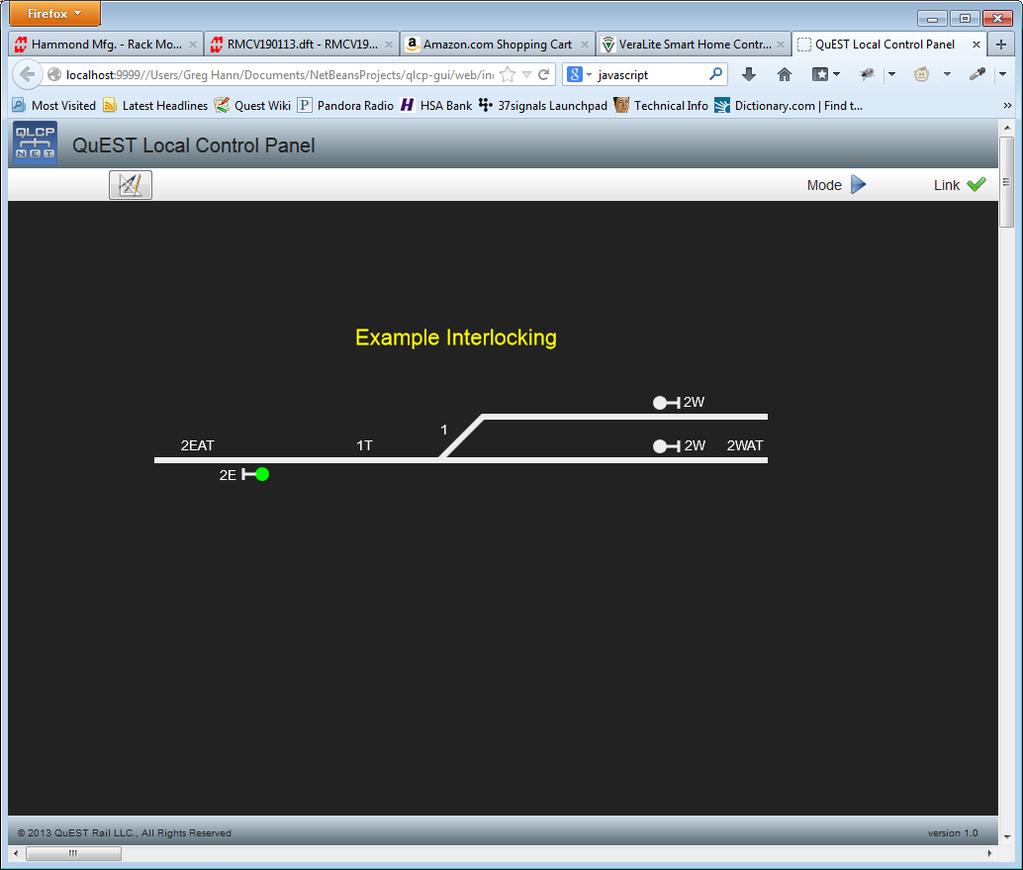
28 QLCP User Manual Page 28 Indication properties change the displayed state of an Icon based on the state of the associated indication bits received. In most cases, the indication is shown as a specific color associated with a track, signal, LED, etc. For switches, position indications are also available to show the switch in the normal and reverse positions. When a bit/status name is assigned to an indication, you must also select in which state (true or false) it will display that indication. As shown in the screenshot above, the 2EGK indication will display a red signal when it is false and a lime signal when it is true. Run Mode (For Panel Design Verification) In Run Mode, you can test the bit assignments of your panel using the control and indication tables in the Graphical Control Panel tab of the QLCP- NET Developer Tool. In Run Mode, the Control Panel is displayed without a grid and without the Design Mode buttons as shown in the example below. You can click on the Design button to return to Design Mode.
29 QLCP User Manual Page 29 Sending Controls in Run Mode for Testing Panel Bit Assignments To send a control, click on an Icon to display its Controls dialog box. If controls have been configured, you will see its custom- named buttons as shown in the example screenshot below. The 2E signal has a 2E Clear and a 2 Stop control button. These buttons appear as a result of assigning control bits/status names and custom button names to the Icons properties while in Design mode. When you click on a control button in the Control Panel, you should see the associated control bit change state (yellow = true, white = false) in the control table as shown below for the 2E Clear button. This verifies that you have made the correct bit assignment. Note: The control buttons are momentary. The control bit is sent as a 1 when the button is pressed and sent as a 0 when the button is released. The check boxes are used for latching control bits. This feature is not supported in offline design/test mode.
30 QLCP User Manual Page 30 Monitoring Indications in Run Mode for Testing Panel Bit Assignments When you right- click on an indication bit in the indication table, you toggle its state. When you toggle a bit s state, you should see the associated icon in the Control Panel change color based on the bit assignment as shown below for the 2E signal. This verifies that you have made the correct bit assignment.

31 QLCP User Manual Page 31
32 QLCP User Manual Page 32 Saving and Opening Panel Files Use the Save button in the Main Menu bar of Design Mode to save a panel file. The saved file will be given a cpf extension. Use the Open button to open and load your saved panel files. After saving your Control Panel design, you can close Firefox at any time. Uploading and Downloading Panel Files You must be connected to the QLCP- NET to upload and download Control Panel files. To upload a Control Panel file to a QLCP- NET, click on the Upload Panel button in the Graphical Control Panel tab and select the Control Panel file to upload. To download a Control Panel file from a QLCP- NET, click on the Download Panel button in the Graphical Control Panel tab and save the file to any directory with a file name of your choosing. Using the Graphical Control Panel for Local Control To access the Graphical Control Panel of a QLCP- NET for the purposes of local control, open the Firefox web browser on your computer and enter the QLCP s IP address for the URL. The QLCP- NET will serve the Control Panel web page with an open dialog box that provides the QLCP s location information. This dialog box does not prevent access but is intended to make sure the user is aware of which location is being accessed. The location information displayed is user- defined in the configuration file. The screenshot below shows the Control Panel page when it is first requested from the QLCP.

33 QLCP User Manual Page 33 If the location information is what you expected for the IP address you entered as a URL, click on the Close button of the dialog box to continue. Caution! If this is not the location you expected, it is recommended that you close the web page. After clicking on the Close button of the Control Panel Request dialog box, you will see the location s Control Panel as shown in the example screenshot below.
34 QLCP User Manual Page 34 The Main Menu Bar has two buttons, Send All Controls and Clear All Controls. It also displays the current mode (Run Mode) and the Link Health status. Send All Controls Link Health Clear All Controls Run Mode There are two ways to send controls. Click on an Icon to display its Controls dialog box. Then you can click on a control button to send a momentary control. In other words, a bit value of 1 will be sent when the button is clicked (mouse down), and then a bit value of 0 will be sent when the button is released (mouse up). You can also send a latched control by clicking on
35 QLCP User Manual Page 35 the checkbox next to the control button and then clicking on the Send All Controls button in the Main Menu Bar. When a control s checkbox is enabled, the control bit will be set to a value of 1 and the associated momentary button will be disabled. You can latch multiple bits in multiple icons and then send them together using the Send All Controls button. You can clear all latched control bits using the Clear All Controls button. This will clear the bits, but you still need to click on the Send All Controls button for the cleared bits to take effect.
 Serial Cable Supplied with QLCP Bulkhead Kit 1 2 3 4 5 6 7 8 ON DS1 OFF 1 1 5V COM 5V COM LEDs (Common")
36 QLCP User Manual Page 36 6 Application Examples LCP for the GETS ElectroLogIXS Note that an older QLCP version without the CLI is shown. The CLI can also be used for this application. QLCP RS- 232 Serial Cable for ElectroLogIXS QLCP Bulkhead Kit To Signal Battery (B12/N12) Serial Cable Supplied with QLCP Bulkhead Kit ON DS1 OFF 1 1 5V COM 5V COM LEDs (Common Cathode) Normally Open Pusbuttons
37 QLCP User Manual Page 37 LCP for the GETS ElectroLogIXS with Duplication Note that an older QLCP version without the CLI is shown. The CLI can also be used for this application. QLCP RS- 232 Serial Cable for ElectroLogIXS Ethernet Cable Serial Cable Supplied with QLCP Bulkhead Kit To Signal Battery (B12/N12) QLCP Bulkhead Kit QLCP Bulkhead Kit To Signal Battery (B12/N12) ON DS1 OFF 5V COM 5V COM ON DS1 OFF 5V COM 5V COM LEDs (Common Cathode) Normally Open Pusbuttons LEDs (Common Cathode) Normally Open Pusbuttons Network Role: Server IP Address: I/O Bank Number: 1 Network Role: Client IP Address: Server IP Address: I/O Bank Number: 1
38 QLCP User Manual Page 38 LCP for the Ansaldo STS MicroLok II QLCP RS- 485 Serial Cable for MicroLok II QLCP Bulkhead Kit To Signal Battery (B12/N12) Serial Cable Supplied with QLCP Bulkhead Kit ON DS1 OFF 1 5V COM 1 5V COM JP3 4W 1 2W 4W 1 2W JP4 JP5 TERM 1 LEDs (Common Anode) Normally Open Pusbuttons
 QLCP Bulkhead Kit QLCP Bulkhead Kit To Signal Battery (B12/N12) 1 2 3 4 5 6 7 8 ON DS1 OFF 5V COM 5V COM 1 2 3 4 5 6 7 8 ON DS1 OFF 5V COM 5V COM Main Panel")
39 QLCP User Manual Page 39 LCP for the Ansaldo STS MicroLok II with Expansion and Duplication QLCP RS- 232 Serial Cable for MicroLok II HB Industrial Ethernet Switch Serial Cable Supplied with QLCP Bulkhead Kit To Signal Battery (B12/N12) QLCP Bulkhead Kit QLCP Bulkhead Kit To Signal Battery (B12/N12) ON DS1 OFF 5V COM 5V COM ON DS1 OFF 5V COM 5V COM Main Panel LEDs (Common Cathode) Normally Open Pusbuttons LEDs (Common Cathode) Normally Open Pusbuttons Network Role: Server IP Address: I/O Bank Number: 1 Network Role: Client IP Address: Server IP Address: I/O Bank Number: 2 To Signal Battery (B12/N12) QLCP Bulkhead Kit QLCP Bulkhead Kit To Signal Battery (B12/N12) ON DS1 OFF 5V COM 5V COM ON DS1 OFF 5V COM 5V COM Duplicate Panel LEDs (Common Cathode) Normally Open Pusbuttons LEDs (Common Cathode) Normally Open Pusbuttons Network Role: Client IP Address: Server IP Address: I/O Bank Number: 1 Network Role: Client IP Address: Server IP Address: I/O Bank Number: 2
40 QLCP User Manual Page 40 LCP for the GETS VHLC The application of the QLCP when used with a GETS VHLC is very similar to the application examples shown above for the GETS ElectroLogIXS. To interface the QLCP with a VHLC, you may use the Current Loop Adapter (CLA), RS- 232 or RS- 485 serial port module on Port E of the VHLC. There is no special software configuration/setting required by the VHLC for any of those interfaces. In fact, it is completely transparent to the VHLC as to whether a CLA, RS- 232, or RS- 485 module is installed on port E.
 Update Network SW (QLCP- NET only) Update Web GUI SW (QLCP- NET only) The current versions of the Executive")
41 QLCP User Manual Page 41 7 Updating QLCP Software Update the QLCP software using the QLCP- NET Developer Tool. The Software interface is shown below. There are three buttons for updating the software: Update Executive SW (QLCP and QLCP- NET) Update Network SW (QLCP- NET only) Update Web GUI SW (QLCP- NET only) The current versions of the Executive Software and Network Software are shown in the button bar of the Software tab (shown below). The current version of the Web GUI Software is shown in the footer of the web page when the Graphical Control Panel is displayed in a web browser.
42 QLCP User Manual Page 42 Follow the steps below (which are also provided in the tool interface) to update the QLCP Executive Software, Network Software, and Web GUI Software. Warning! If it is required to update both the Executive and Network software, update the Network software first. Updating the Executive Software: The System Configuration (USB) Port is used to update the QLCP Executive Software as follows: 1. Turn on the QLCP Power Switch. 2. Connect a PC to the QLCP System Configuration Port using a USB cable. The QLCP accepts a standard type B male USB connector. 3. Click on the Update Executive SW button. The programmer will open and display a message that a device has been detected. 4. Select the.s19 file to load onto the QLCP. Note: It is not required to power cycle the QLCP after updating the Executive Software. The QLCP will reset itself. Updating the Network Software: The Ethernet Port is used to update the QLCP Network Software as follows: 1. Turn on the QLCP Power Switch. 2. Connect a PC to the QLCP- NET Ethernet Port using an Ethernet cable (Note: It is recommended to perform this update through a direct connection to ensure a successful, uninterrupted transfer of the image). 3. Enter the QLCP s IP address and password and then click on the Connect button. 4. Click on the Update Network SW button. 5. Select the.img file to upload to the QLCP- NET. Note: It is required to power cycle the QLCP after updating the Network Software. Updating the Web GUI Software: The Ethernet Port is used to update the QLCP Web GUI Software as follows: 1. Turn on the QLCP Power Switch.
43 QLCP User Manual Page Connect a PC to the QLCP- NET Ethernet Port or network using an Ethernet cable. 3. Enter the QLCP s IP address and password and then click on the Connect button. 4. Click on the Update Web GUI SW button. 5. Select the.zip file to upload to the QLCP- NET. Note: It is not required to power cycle the QLCP after updating the Web GUI Software.
44 QLCP User Manual Page 44 8 Troubleshooting For troubleshooting purposes, the QLCP offers the following: Message Traffic Monitor (in the System Configuration Port Terminal Interface) Connected Clients Tab (in the QLCP- NET Developer Tool) Status LEDs Help Tab (in the QLCP- NET Developer Tool) Message Traffic Monitor The Message Traffic Monitor is an option in the System Configuration Port Terminal Interface menu that displays serial message traffic between the QLCP and the interlocking controller. This feature can be used to determine whether communications between the QLCP and the interlocking controller is functioning correctly. Connected Clients Tab For a QLCP- NET configured as a Server, this tab in the QLCP- NET Developer Tool displays the connected Client QLCPs. This can be helpful in troubleshooting connectivity issues between QLCP Clients and their Server. Status LEDs The QLCP has several status LEDs that provide status information. The following LEDs can be used for troubleshooting: Power LED System Health LED Local Link Health LED Network Link Health LED Link Activity TX and RX LEDs for CLI, RS- 232, and RS- 485 Network Port LEDs

45 QLCP User Manual Page 45 Help Tab In the QLCP- NET Developer Tool Help tab, you can mouse over the QLCP image to identify user interfaces and other points of interest. Tool tips pop up providing brief descriptions. To learn more, click on the point of interest. Click on the User Manual button to access this manual.
46 QLCP User Manual Page 46 9 For Reference Local Control Serial Port (Isolated Current Loop Interface) The CLI serial interface (DB9 male connector P1) pin- out is shown below. Pin Signal 1 RXD+ 2 RXD- 4 TXD+ 5 TXD- Local Control Serial Port (Isolated RS- 232) The RS- 232 serial interface (DB9 male connector J6) conforms to the standard as called out for DTE (Data Terminal Equipment) devices. The pin- out for this connector is shown below. Note: Flow control is currently not implemented. Pin Signal 2 RXD 3 TXD 5 GND 7 RTS 8 CTS Local Control Serial Port (Isolated RS- 485) The RS- 485 serial interface (DB9 male connector J7) can operate in two- wire mode (half- duplex) or four- wire mode (full- duplex). The RS- 485 interface is asynchronous, meaning that no clock is present. The pin- out for this connector is shown below. Note: The RS- 485 interface must be configured for four- wire mode for GETS LCP and PEER protocols. Pin Signal 2 RX- 3 TX-
47 QLCP User Manual Page 47 4 TX+ 5 SR 9 RX+ System Configuration DIP Switch The System Configuration DIP Switch (DS1) provides a means for basic configuration of the QLCP. For applications that use the RS- 232 port with GETS LCP protocol (factory default), the QLCP can be fully configured using the System Configuration DIP Switch (and jumpers). In fact, the System Configuration DIP Switch settings are consistent with the GETS CLCP Controller. Note that, like the GETS CLCP Controller, the DIP Switch settings are also sent as control bits 9 through 15. This allows the QLCP to be a direct replacement for the GETS CLCP. The following table shows the System Configuration DIP Switch settings. Position OFF ON 1 Not Used Not Used 2 Not Used Not Used 3 Not Used Not Used 4 Not Used Not Used 5 Normal Loopback (self- test) 6 Common Anode Common Cathode 7 Normal Invert Inputs 8 Normal Factory Test
Industrial Serial Device Server
 1. Quick Start Guide This quick start guide describes how to install and use the Industrial Serial Device Server. Capable of operating at temperature extremes of -10 C to +60 C, this is the Serial Device
NCOM SERIAL DEVICE SERVER 4XX SERIES USER S MANUAL
 NCOM SERIAL DEVICE SERVER 4XX SERIES USER S MANUAL 2017-07-07 Edition Titan Electronics Inc. Web: www.titan.tw Contents 1. INTRODUCTION... 4 1.1 Key Features... 5 1.2 Specifications... 6 2. PANEL LAYOUT
This 4-port RS-422/485 Adapter is provided with an external switching power adapter in the package.
 USB-4COMi-M USB to Quad RS-422/485 to Serial Adapter Manual The USB to Industrial Quad RS-422/485 Adapter is designed to make industrial communication port expansion quick and simple. Connecting to a USB
Lantech LSC-1102B SERIAL TO TCPIP CONVERTER. User Manual
 Lantech LSC-1102B SERIAL TO TCPIP CONVERTER User Manual V1.0 Sep 2016 Table of Contents 1. Introduction 3 Overview 4 Product Specifications 8 2. Description & Installation 10 Product Panel Views 10 LED
Quick Start Guide. 2-Port 10/100 Device Server RS-232/422/485 DB9 M. Access two serial RS-232 or RS-422/485 devices over a 10- or 100-Mbps network.
 LES302A LES302A-KIT LES302AE-KIT 2-Port 10/100 Device Server RS-232/422/485 DB9 M Quick Start Guide Access two serial RS-232 or RS-422/485 devices over a 10- or 100-Mbps network. Customer Support Information
NCOM SERIAL DEVICE SERVER 1XX SERIES USER S MANUAL
 NCOM SERIAL DEVICE SERVER 1XX SERIES USER S MANUAL 2017-07-07 Edition Titan Electronics Inc. Web: www.titan.tw Contents 1. INTRODUCTION... 4 1.1 Key Features... 5 1.2 Specifications... 6 2. PANEL LAYOUT
USB-16COMi-M 16-Port RS-422/485 USB Serial Adapter User Manual. Features and Specifications. Power Supply
 USB-16COMi-M 16-Port RS-422/485 USB Serial Adapter User Manual The USB to industrial 16-Port RS-422/485 Adapter is designed to make serial port expansion quick and simple. Connecting to a USB port on your
GEM80 & ewon Setup Quick Guide
 Introduction to the ewon The ewon is an intelligent, programmable Ethernet Gateway, which can be used to bridge GEM 80 PLCs onto an Ethernet network, via the PLC serial port (Port3). This provides network-based
USB-COMi-TB USB to Industrial Single RS-422 / 485 Adapter Manual. Specifications and Features
 USB-COMi-TB USB to Industrial Single RS-422 / 485 Adapter Manual The USB-COMi-TB USB-to-Industrial Single RS-422/485 Adapter is designed to make industrial communication port expansion quick and simple.
Embedded Modbus TCP Module GS11-MT. User Manual REV 1.1. SST Automation.
 Embedded Modbus TCP Module GS11-MT User Manual REV 1.1 SST Automation E-mail: SUPPORT@SSTCOMM.COM WWW.SSTCOMM.COM Catalog 1 About the Embedded Module... 4 1.1 General...4 1.2 Features... 4 1.3 Specifications...4
8 Port USB to RS- 232/422/485 Octal Adapter. Product Manual. Coolgear, Inc. Version 1.1 April 2018 Model Number: USB-8COMi-RM.
 8 Port USB to RS- 232/422/485 Octal Adapter Product Manual Coolgear, Inc. Version 1.1 April 2018 Model Number: USB-8COMi-RM 2 USB-8COMi-RM Product Manual Revision History Revision Date Author Comments
USER S MANUAL. PH232Ex1. #1 RS-232 Serial Port to Ethernet, Terminal Server/Client. Doc No: PH232Ex1-UM-001 IPEX. (IP Electronix)
") USER S MANUAL PH232Ex1 Doc No: PH232Ex1-UM-001 #1 RS-232 Serial Port to Ethernet, Terminal Server/Client IPEX (IP Electronix) Contents 1. INTRODUCTION... 3 2. SPECIFICATIONS... 3 3. PACKAGE CHECKLIST...
USER S MANUAL PH232Ex1 Doc No: PH232Ex1-UM-001 #1 RS-232 Serial Port to Ethernet, Terminal Server/Client IPEX (IP Electronix) Contents 1. INTRODUCTION... 3 2. SPECIFICATIONS... 3 3. PACKAGE CHECKLIST...
User Manual A08. User Manual
 A08 TABLE OF CONTENTS TABLE OF CONTENTS... 1 1. INTRODUCTION... 2 1.1. Key Features... 3 1.2. OS Requirement... 4 1.3. Specification... 4 1.4. Packing List... 4 2. OVERVIEW... 5 2.1. LED Definition...
RM024 DVK USER GUIDE VERSION 1.2
 USER GUIDE VERSION 1.2 Americas: +1-800-492-2320 Asia: +852-2923-0610 REVISION HISTORY Version Revision Date Change Description Approved By 1.0 20 Dec 2012 Initial Release Chris Downey 1.1 15 Apr 2014
Introduction & Specifications of Hi-Speed USB to Industrial Dual Ports RS-422/485 Adapter
 Introduction & Specifications of Hi-Speed USB to Industrial Dual Ports RS-422/485 Adapter USB to Dual RS-422/485 Adapter (USB-2COMi-M) USB to Dual Opto-isolated RS-422/485 Adapter (USB-2COMi-SI-M) - with
USER MANUAL FOR GS100/GS1003G
 USER MANUAL FOR GS100/GS1003G 1 Table of Contents 1. INTRODUCTION... 3 2. FEATURES... 3 3. OPERATION... 3 4.CONNECTION DETAILS... 4 5.CONFIGURATION... 5 5.1 Hyper Terminal Setting... 5 5.2 GS100 Configuration...
May 2016 Version 1.2.7
 May 2016 Version 1.2.7 2 Introduction Copyright Copyright 2016 4RF Limited. All rights reserved. This document is protected by copyright belonging to 4RF Limited and may not be reproduced or republished
Installation Guide of Hi-Speed USB to Industrial I/O Adapter
 Installation Guide of Hi-Speed USB to Industrial I/O Adapter Introduction of USB-COMi-SI-M The USB Industrial I/O Adapter is designed to make industrial communication port expansion quick and simple. Connecting
EX KVIS RS232/422/485 3-in-1 Serial to USB Adapter (w/ 4KV Isolation, 15KV ESD Surge Protection)
") EX-1331-4KVIS RS232/422/485 3-in-1 Serial to USB Adapter (w/ 4KV Isolation, 15KV ESD Surge Protection) 1. Introduction Thank you for purchasing this RS232/422/485 3-in-1 Serial to USB Adapter. It is an
EX-1331-4KVIS RS232/422/485 3-in-1 Serial to USB Adapter (w/ 4KV Isolation, 15KV ESD Surge Protection) 1. Introduction Thank you for purchasing this RS232/422/485 3-in-1 Serial to USB Adapter. It is an
Canlan INSTALLATION MANUAL
 Canlan INSTALLATION MANUAL August 2014 Table of Contents Introduction... 4 Overview... 5 RJ45 Connector and Status LEDs... 5 Power Input... 6 RS232 / RS485 Connectors... 7 Installing the Canlan Software...
DGH A3000 Configuration Guide For use with DGH Modules
 DGH A3000 Configuration Guide For use with DGH Modules Revision Date: 12/07/05 Version: 1.00 Contact Information: http://www.dghcorp.com Ph: (603) 622-0452 Fax: (603) 622-0487 Mailing Address: DGH Corporation
Installation Guide of Hi-Speed USB to Octal RS-232/422/485 Adapter
 Installation Guide of Hi-Speed USB to Octal RS-232/422/485 Adapter Introduction The USB to Octal Serial Adapter is designed to make serial port expansion quick and simple. Connecting to a USB port on your
3.1 I-7560 Pin Assignment and Specifications: Introduction
 3.1 I-7560 Pin Assignment and Specifications: Introduction The I-7560 adds a Windows serial Com port via its USB connection and is compatible with new & legacy RS-232 devices. USB Plug and Play allows
i-7550 PROFIBUS to RS-232/422/485 Converter User's Manual High Quality, Industrial Data Acquisition, and Control Products
 i-7550 PROFIBUS to RS-232/422/485 Converter User's Manual High Quality, Industrial Data Acquisition, and Control Products i-7550 PROFIBUS to RS-232/422/485 Converter User's Manual (Version 1.01) PAGE:1
INDEX. Document Name : User Manual for SC10EJ Serial to Ethernet Converter
 Document Name : User Manual for SC10EJ Serial to Ethernet Converter Page 1 of 10 INDEX 1. Technical Specifications 1 2. Modes of Operation 1 3. Configuring the SC10 EJ : Through Serial Port 2 a. Configuring
Installation Guide of Hi-Speed USB to Industrial Single RS-422/485 Adapter
 Installation Guide of Hi-Speed USB to Industrial Single RS-422/485 Adapter Introduction of USB-COMi and USB-COMi-SI The USB-COMi and USB-COMi-SI Industrial Single RS-422/485 Adapters are designed to make
Product Manual. 2 Port USB to RS-422 /485 Optical Isolated Adapter. Coolgear, Inc. Version 1.1 March 2018 Model Number: USB-2COMi-Si-M
 2 Port USB to RS-422 /485 Optical Isolated Adapter Product Manual Coolgear, Inc. Version 1.1 March 2018 Model Number: USB-2COMi-Si-M 2 USB-2COMi-Si-M Product Manual Revision History Revision Date Author
Ethernet Serial Server
 Ethernet Serial Server Users Manual Eport-101, Eport-102, Eport-104, Eport108 1 INTRODUCTION... 1 1.1 FEATURES... 1 1.2 PRODUCT SPECIFICATIONS... 2 1.3 DEFAULT SETTINGS... 3 2 COMMUNICATION MODES... 4
INSTALLATION GUIDE Maxiflex P3e CPU M1262F
 INSTALLATION GUIDE Maxiflex P3e CPU M1262F Introduction This Installation Guide is intended to aid the fitment of the M1262B CPU in the field. For operating details of this product, refer to the Users
Installation and Programming Manual. Niobrara Research & Development Corporation P.O. Box 3418 Joplin, MO USA
 DUCM DF1 Manual DUCM DF1 Installation and Programming Manual This manual describes the DUCM application for interfacing DF1 slaves to a Modbus or RNIM serial network. Effective: February 16, 2017 Niobrara
Installation Guide of Hi-Speed USB-to-Optically Isolated RS-422/485 Adapter
 Installation Guide of Hi-Speed USB-to-Optically Isolated RS-422/485 Adapter Introduction of ES-U-2101-M The USB-to-Optically Isolated RS-422/485 Adapter is designed to make industrial communication port
MGate MB3000 Modbus Gateway User s Manual
 User s Manual Seventh Edition, May 2013 www.moxa.com/product 2013 Moxa Inc. All rights reserved. User s Manual The software described in this manual is furnished under a license agreement and may be used
USB to RS-232/RS422/485. US-101-I USB To Serial Operation Manual
 USB to RS-232/RS422/485 US-101-I USB To Serial Operation Manual First Edition, Jun 2008 Table of Contents 1. Introduction 2 2. Package checklist 3 3. Product Specification 4 4. Product Panel Views Description
ICD200A Quick Start Guide. Convert RS-232 data signals to RS-422/485 signals in heavy industrial areas.
 Industrial Opto-Isolated RS-232 to RS-422/485 Converter Convert RS-232 data signals to RS-422/485 signals in heavy industrial areas. Rugged IP30-rated metal case for panel mounting. Quick Start Guide Customer
Title: Using the AUX Port.
 Title: Using the AUX Port. Article Number: 1090 Date: 03/15/05 Information in this article applies to: HMI Silver Series (Enhanced Versions OIT Product(s All Controller (PLC Product(s N/A Summary HMI generation
SCADALink IP100 SCADA Terminal Server QUICK START GUIDE Revision 1.42 June 19, 2012
 SCADA Terminal Server QUICK START GUIDE Revision 1.42 June 19, 2012 www.scadalink.com INTRODUCTION Use this Quick Start Guide to configure a SCADALink IP100. Full documentation is found under the IP100
USBG-8COM-PRO 8-Port USB to RS-232, 422, 485 Auto Setup Adapter Manual. Features & Specifications. Specifications
 USBG-8COM-PRO 8-Port USB to RS-232, 422, 485 Auto Setup Adapter Manual The USBG-8COM-PRO 2-Port Series Industrial I/O Adapters are advanced USB to Serial Adapters that connect to 1, 2, 4 or 8 RS- 232/422/485
Ethernet Interface Module
 Interface Manual 1 Ethernet Interface Module SignalFire Number: ENET-DIN The SignalFire Ethernet Gateway has the following features: - Wide range DC power input. 6 to 36VDC - Power Over Ethernet (POE)
NordField Electronics
 NordField Electronics XS1000 TCP/IP to RS232/422/485 Device Server Overview and quick info sheet 3.0. Hardware Installation & Initial Setup 3.1 RS-232 Configuration:(DB9 Male) (DB9Male) Signal I/O PIN2
User s Guide. Ethernet Module for Barcode Printer
 User s Guide Ethernet Module for Barcode Printer 1. ETHERNET MODULE... 2 1-1. Functions... 2 1-2. General Specifications... 2 2. ETHERNET MODULE INSTALLATION... 3 2-1. Ethernet Module Installation for
IPM-01 / IPM-01H MODBUS TCP/RTU Bridge User Guide
 VxI Power Ltd. IPM-01 / IPM-01H MODBUS TCP/RTU Bridge User Guide 01/12/2015 Document Number: 14970-020A Issue Number: 2 Contents 1.0 Device Overview... 2 2.0 Getting Started... 3 2.1 Connecting the Device...
EtherSeries. EtherSeries CR-2. CR-2-Opto. User s Guide. Revised October 7, 2013 Firmware Version 1.X
 EtherSeries EtherSeries CR-2 & CR-2-Opto User s Guide Revised October 7, 2013 Firmware Version 1.X TABLE OF CONTENTS SECTION 1 - DESCRIPTION... 2 SECTION 2 - SPECIFICATIONS... 4 SECTION 3 - INSTALLATION...
Installation and User Guide
 Installation and User Guide Trademarks and Notices Notice Comtrol Corporation. SPECIFICALLY DISCLAIMS THE IMPLIED WARRANTIES OF MERCHANTABILITY AND FITNESS OF THIS PRODUCT FOR A PARTICULAR PURPOSE. Comtrol
VirtualSCADA VSU-485G USB to RS422/485 Isolated Converter User Manual
 VirtualSCADA USB to RS422/485 Isolated Converter User Manual Revision 1.01.00 Page 1 (15) Table of contents Warranty and support... 3 Product return... 3 1 About the VirtualSCADA USB to RS422/485 Converter...
Forcom Technology Co., Ltd. Intelligent RS-485/422 to RS-232 converter
 Forcom Technology Co., Ltd. Tel: +886-2-77296880 Fax: +8862-27055495 e-mail: info@forcomtech.com.tw URL: http://www.forcomtech.com.tw Intelligent RS-485/422 to RS-232 converter Model No.: R32TR1 AD-INT
Document Name: User Manual for SC10MK, Modbus RTU to Modbus TCP Converter
 Document Name: User Manual for SC10MK, Modbus RTU to Modbus TCP Converter Login for the first time, please use http://192.168.1.100 To key in user name and password is for identifying authorization. Default
Korenix JetCard Series Multiport Serial Card/Ethernet Switch Card User s Manual
 Korenix JetCard Series Multiport Serial Card/Ethernet Switch Card User s Manual Third Edition, Dec. 2008 www.korenix.com Korenix JetCard Series Multiport Serial Card/Ethernet Switch Card User s Manual
Quick Installation Guide
 Nextiva HDR 1800 High-Definition Receiver Version 1.0 Quick Installation Guide All users should read the Nextiva HDR 1800 User Guide for complete details on installation, usage and functionality. This
Overview. Table of contents
 1 Table of contents Overview... 1 Applications... 2 Connecting and adjusting of converter... 3 Communication parameters adjusting... 5 RealPort - virtual serial port... 12 Installing virtual serial port
ProjectorNetTM Adapter Quick Start Guide
 ProjectorNetTM Adapter Quick Start Guide Adapter networking 1. Quick Start The ProjectorNet Adapter kit contains the following items: ProjectorNet Serial to Ethernet Adapter Cable Adapter, ProjectorNet
BCOM-USB Device. User Manual.
 BCOM-USB Device User Manual www.kalkitech.com Version 2.1.2, December 2017 Copyright Notice 2017 Applied Systems Engineering, Inc. All Rights reserved. This user manual is a publication of Applied Systems
HART / EtherNet/IP Gateway GT200-HT-EI User Manual V 1.0 REV A SST Automation
 HART / EtherNet/IP Gateway GT200-HT-EI V 1.0 REV A SST Automation E-mail: SUPPORT@SSTCOMM.COM WWW.SSTCOMM.COM Catalog 1 Product Overview... 4 1.1 Product Function...4 1.2 Product Features... 4 1.3 Technical
Installation and Programming Manual
 QUCM DF1 Application Manual QUCM DF1 Installation and Programming Manual This Manual describes the QUCM application for interfacing Allen-Bradley DF1 devices to a master of another protocol, including
EX-6014WI RS232 to WiFi Wireless Adapter, w/ Mounting Kit
 EX-6014WI RS232 to WiFi Wireless Adapter, w/ Mounting Kit Thank you for purchasing this RS232 to WiFi Wireless Adapter (hereinafter referred to as WiFi-Adapter ), it is designed to communicate with RS232
I-7570 Serial To HART Converter
 I-7570 Serial To HART Converter User s Manual Warranty All products manufactured by ICP DAS are under warranty regarding defective materials for a period of one year from the date of delivery to the original
I-7560U/7561U/7563U. User Manual WARRANTY WARNING COPYRIGHT TRADEMARKS CONTACT US
 I-7560U/7561U/7563U User Manual USB tto RS--232//422//485 Converrtterrss Verr.. 1..0,, Decc.. 2013 WARRANTY All products manufactured by ICP DAS are warranted against defective materials for a period of
MGate TM EIP3000 DF1 to EtherNet/IP Gateway User s Manual
 MGate TM EIP3000 DF1 to EtherNet/IP Gateway User s Manual First Edition, June 2009 www.moxa.com/product 2009 Moxa Inc. All rights reserved. Reproduction without permission is prohibited. MGate EIP3000
MODEL 2310 AL MCS-11 REMOTE ENCODER. FIAL INCORPORATED 710 Center Street Oregon City, OR
 MODEL 2310 AL MCS-11 REMOTE ENCODER FIAL INCORPORATED 710 Center Street Oregon City, OR 97045 503.607.1940 WWW.FIAL.COM DOCUMENT NUMBER FC2310_AL-040506 COPYRIGHT 2004 BY FIAL INCORPORATED NOTICE OF FCC
USB-COM Plus ISO (USB-COMi SI-M)
") VS Vision Systems GmbH / Part Number 603 Features 1 x RS232/422/485 port USB 2.0 Full Speed interface 2.5kV isolation per serial port USB and serial ports ESD protected Robust metal case Jumperless, DIP
VS Vision Systems GmbH / Part Number 603 Features 1 x RS232/422/485 port USB 2.0 Full Speed interface 2.5kV isolation per serial port USB and serial ports ESD protected Robust metal case Jumperless, DIP
EtherSeries Modbus Gateway EMB-2 User s Guide
 EtherSeries Modbus Gateway EMB-2 User s Guide Revised March 25, 2004 Firmware Version 1.4 FCC Statement This device complies with the limits for a Class B digital device, pursuant to Part 15 of the FCC
Modbus TCP / RTU Gateway
 Modbus TCP / RTU Gateway Manual for models IE-GW-MB-2TX-1RS232/485 IE-GWT-MB-2TX-1RS232/485 First Edition, May 2014 1536320000/00/05.14 Modbus TCP / RTU Gateway Manual IE-GW-MB-2TX-1RS232/485 IE-GWT-MB-2TX-1RS232/485
D8000 SERIES QUICK START GUIDE
 D8000 SERIES QUICK START GUIDE Version 1.0 Overview The D8000 series modules require a DC Voltage power supply, a USB cable and an unused computer USB port for proper operation. Connecting the D8000 series
TRP-C08. USB to RS232/422/485 Isolated Converter. User s Manual. Printed Sep.2014 Rev 1.4
 TRP-C08 USB to RS232/422/485 Isolated Converter User s Manual Printed Sep.2014 Rev 1.4 Trycom Technology Co.,Ltd No.35, Zhongxing Rd., Guishan Township, Taoyuan County 333, Taiwan. Tel : 886-3-350-3351
GW1000 User s Guide. Revision 1.04 Mar 30, 2008
 GW1000 User s Guide Revision 1.04 Mar 30, 2008 Website: www.datalink-networks.com Tel : (604) 632-4278 / (866) 709-6390 Table of Contents 1.0 GW1000 General Operation & Applications... 3 2.0 Hardware Specifications...
Title: Using the AUX Port.
 Title: Using the AUX Port. Article Number: 1090 Date: 07/10/06 Information in this article applies to: HMI Silver Series (Enhanced Versions) OIT Product(s) All Controller (PLC) Product(s) N/A Summary HMI
USB to RS-232/RS422/485. URK-228-I USB To Serial Operation Manual
 USB to RS-232/RS422/485 URK-228-I USB To Serial Operation Manual First Edition, Feb 2012 Table of Contents 1. Introduction 2 2. Package checklist 3 3. Product Specification 4 4. Product Panel Views Description
STAR Comm Modem Kit for the Micro/PX-2000: Setup Instructions
 STAR Comm Modem Kit for the Micro/PX-2000: Setup Instructions This STAR Comm Modem Kit was designed specifically for use with the Micro/PX-2000 micro. The STAR Comm Modem is an external modem that can
RTU560 Remote Terminal Unit Connections and Settings
 Remote Terminal Unit Connections and Settings Communication Unit 560CMG10 Application, characteristics and technical data have to be taken from the hardware data sheet: 560CMG10 1KGT 150 645 Operation
Matrix-710. Linux-Ready Cortex-A5 Industry IoT Gateway. Hardware Guide. Version: Nov.
 Matrix-710 Linux-Ready Cortex-A5 Industry IoT Gateway Hardware Guide Version: 1.01 2017 Nov. Copyright Artila Electronics Co., Ltd. All Rights Reserved Trademarks The Artila logo is a registered trademark
Document Name: User Manual for SC10EK4 Serial to Ethernet Converter with 4 TCP Sockets. Index
 Document Name: User Manual for SC10EK4 Serial to Ethernet Converter with 4 TCP Sockets. Index Technical Specifications 1 Installation Procedure 1 LED Indications 2 Configuration Procedure Configuration
LM300 Manager User Manual. Document Version: 1.1 LM300 Firmware Version: Bluetooth Firmware Version:
 LM300 Manager User Manual Document Version: 1.1 LM300 Firmware Version: 2.0.1 Bluetooth Firmware Version: 7.5.4279 LM300 Bluetooth Ethernet Access Point LM300 Manager User Manual i Revision Date Description
USER S MANUAL. PH485Ex1. #1 RS-485 Serial Port to Ethernet, Terminal Server/Client. Doc No: PH485Ex1-UM-001 IPEX. (IP Electronix)
") USER S MANUAL PH485Ex1 Doc No: PH485Ex1-UM-001 #1 RS-485 Serial Port to Ethernet, Terminal Server/Client IPEX (IP Electronix) Contents 1. INTRODUCTION... 3 2. SPECIFICATIONS... 3 3. PACKAGE CHECKLIST...
USER S MANUAL PH485Ex1 Doc No: PH485Ex1-UM-001 #1 RS-485 Serial Port to Ethernet, Terminal Server/Client IPEX (IP Electronix) Contents 1. INTRODUCTION... 3 2. SPECIFICATIONS... 3 3. PACKAGE CHECKLIST...
CONTROL MICROSYSTEMS SDI-12 Interface Module. Hardware Manual
 5915 SDI-12 Interface Module Hardware Manual CONTROL MICROSYSTEMS SCADA products... for the distance 48 Steacie Drive Telephone: 613-591-1943 Kanata, Ontario Facsimile: 613-591-1022 K2K 2A9 Technical Support:
MODEL DSU Kbps Rack Mount CSU/DSU OPERATOR S MANUAL. 280 I-80 West Exit 1 PO Box 1330 Verdi NV 89439
 MODEL DSU-56 56 Kbps Rack Mount CSU/DSU OPERATOR S MANUAL 280 I-80 West Exit 1 PO Box 1330 Verdi NV 89439 TEL: 775-345-8000 FAX: 775-345-8010 E-MAIL: SUPPORT @S.NET DSU-56 Rack Mount TABLE OF CONTENTS
User Manual. cmt-svr Startup Guide
 User Manual cmt-svr Startup Guide Table of Contents Chapter 1 Overview... 1 1.1 Specification... 1 1.2 Dimensions... 2 1.3 Connector pin designations... 3 1.4 USB host port and SD card slot... 3 1.5 Ethernet
ICD105A 1008 page 1/ r001 ICD105A. Industrial RS-232 to RS-422/485 Converter
 ICD105A 1008 page 1/5 7319 r001 ICD105A Industrial RS-232 to RS-422/485 Converter Data Rates up to 115.2 Kbps 10 48 VDC Input Power Range Wide Operating Temperature 3-Way 2000V Optical Isolation Modbus
MODEL 2310 MCS-11 REMOTE ENCODER. FIAL INCORPORATED 710 Center Street Oregon City, OR
 MODEL 2310 MCS-11 REMOTE ENCODER FIAL INCORPORATED 710 Center Street Oregon City, OR 97045 503.607.1940 WWW.FIAL.COM COPYRIGHT 2001 BY FIAL INCORPORATED NOTICE OF FCC COMPLIANCE NOTE This equipment has
UR51 Industrial Cellular Router
 UR51 Industrial Cellular Router Quick Start Guide 1 Ursalink Technology Co., Ltd. Welcome Thank you for choosing Ursalink UR51 industrial cellular router. This guide describes how to install the UR51 and
Model XS1000 TCP/IP to RS232/422/485 Device Server User s Manual
 Model XS1000 TCP/IP to RS232/422/485 Device Server User s Manual 3.0. Hardware Installation & Initial Setup 3.1 RS-232 Configuration:(DB9 Male) (DB9Male) Signal I/O PIN2 RXD IN PIN3 TXD OUT PIN5 GND -
Automation Direct (Koyo) Model 192 Interfacing-Windows Version
 Model 192 Interfacing-Windows Version") Logic405 Logic405 Automation (Koyo) Model 192 Interfacing-Windows Version ENGINEERING REPORT No: 97-005W Introduction This report describes interfacing the Model 192 Wireless Modem to programmable controllers.
Logic405 Logic405 Automation (Koyo) Model 192 Interfacing-Windows Version ENGINEERING REPORT No: 97-005W Introduction This report describes interfacing the Model 192 Wireless Modem to programmable controllers.
RTU560 Connections and Settings DIN Rail RTU 560CIG10
 Connections and Settings DIN Rail RTU 560CIG10 Application, characteristics and technical data have to be taken from the hardware data sheet: 560CIG10 1KGT 150 719 Operation The 560CIG10 is a DIN rail
MGate MB3000 Modbus Gateway User Manual
 MGate MB3000 Modbus Gateway User Manual Sixth Edition, July 2012 www.moxa.com/product 2012 Moxa Inc. All rights reserved. MGate MB3000 Modbus Gateway User s Manual The software described in this manual
CommLink IV Technical Guide
 www.wattmaster.com CommLink IV Technical Guide Table of Contents General Information... 3 CommLink IV Overview...3 Optional IP Module Kit...3 Optional Remote Link II...3 Installing CommLink IV ONLY...3
Product Manual. USB to Optical Adapter Industrial Isolated RS- 232/422/485. Coolgear, Inc. Version 2.1 December 2018 Model Number: USB-COMi-Si-M
 USB to Optical Adapter Industrial Isolated RS- 232/422/485 Product Manual Coolgear, Inc. Version 2.1 December 2018 Model Number: USB-COMi-Si-M 2 USB-COMi-SI-M Product Manual Revision History Revision Date
CTC Load Utility TM User Guide
 CTC Load Utility TM User Guide Doc. No. MAN-1050 Copyright 1998 Control Technology Corporation All Rights Reserved. Printed in USA The information in this document is subject to change without notice.
SerialComm ETH-SER-EE9 Serial Device Server / Ethernet to Serial Converter User Manual
 SerialComm ETH-SER-EE9 Serial Device Server / Ethernet to Serial Converter User Manual Version 1.2 - April 22, 2015 CHANGE HISTORY Version Date Description of Changes 1.0 February 16, 2015 Initial Publication
USB Port USB Serial DB-9 RS-232 Adapter FTDI Chipset. Product Manual. Coolgear Version 1.0 January 2018 Model Number: USB2-4COM-M
 USB 2.0 4-Port USB Serial DB-9 RS-232 Adapter FTDI Chipset Product Manual Coolgear Version 1.0 January 2018 Model Number: USB2-4COM-M 2 USB2-4COM-M PRODUCT MANUAL Revision History Revision Date Author
+ (5~27 VDC) GND. Bluetooth V4.1 BLE RS-232 Serial Adapter. Model: BLE-232B. 1. Package content: BLE RS-232 adapter
 GND. Bluetooth V4.1 BLE RS-232 Serial Adapter. Model: BLE-232B. 1. Package content: BLE RS-232 adapter") Bluetooth V4.1 BLE RS-232 Serial Adapter 1. Package content: BLE RS-232 adapter Model: BLE-232B Package Contents: BLE RS-232 adapter x 1 Screw x2, Screw nut x 2 A4 User manual x 1 Mini USB Cable x 1 White
Bluetooth V4.1 BLE RS-232 Serial Adapter 1. Package content: BLE RS-232 adapter Model: BLE-232B Package Contents: BLE RS-232 adapter x 1 Screw x2, Screw nut x 2 A4 User manual x 1 Mini USB Cable x 1 White
NET101. RS232 / RS422 / RS485 to Ethernet Converter. User s Manual. Version 1.2
 NET101 RS232 / RS422 / RS485 to Ethernet Converter User s Manual Version 1.2 Copyright Information Copyright 2004-2005, Mega System Technologies, Inc. All rights reserved. Reproduction without permission
DUCM Hardware. Niobrara Research & Development Corporation P.O. Box 3418 Joplin, MO USA
 DUCM Hardware Manual DUCM Hardware Installation Manual This manual covers the DUCM hardware features and installation procedures. Effective: May 29, 2015 Niobrara Research & Development Corporation P.O.
Intech Micro 2300-A8VI analogue input station MODBUS RTU slave application supplementary manual.
 Intech Micro 2300-A8VI analogue input station MODBUS RTU slave application supplementary manual. MODBUS supplementary manual to the 2300-A8VI Installation Guide. The 2300 series stations are designed to
Universal ipulse Ethernet Adapter. User Manual
 Universal ipulse Ethernet Adapter User Manual January 2011 Table of Contents Introduction 3 Overview 4 Package Checklist 4 Product Features 4 Product Specifications 6 IPulse-e Description & Installation
USB to RS-422/485 Serial Adapter
 USB to RS-422/485 Serial Adapter User Manual Ver. 4.00 All brand names and trademarks are properties of their respective owners. Contents: Chapter 1: Introduction... 3 1.1 Product Introduction... 3 1.2
ES-511, ES-522, ES-551, ES-571. Quick Start Guide. for Brainboxes Ethernet to Serial Range
 ES-511, ES-522, ES-551, ES-571 Quick Start Guide for Brainboxes Ethernet to Serial Range Contents 1. Box Contents Check List 3 2. Hardware 4 3. Network IP Addressing 6 4. Connecting your ES Device 7 5.
ADAM-4510 RS-422/RS-485 Repeater ADAM-4510S Isolated RS-422/485 Repeater ADAM-4520 Isolated RS-422/485 Converter Startup Manual
 ADAM-510 RS-/RS-85 Repeater ADAM-510S Isolated RS-/85 Repeater ADAM-50 Isolated RS-/85 Converter Startup Manual Packing List Before you begin installing your module, please make sure that the following
1 port RS-232 Device Server
 1 port RS-232 Device Server Ethernet RJ45 1 Port Transmit and receive and Ethernet Link and 100/10M LED drive. 10/100 Mbps, auto MDI/MDIX Gateway IP address Serial Interface 1 Port 15 KV ESD protection
PACSystems* RX3i IC695CMM002-EG and IC695CMM002CA-EG IC695CMM004-EG, IC695CMM004CA-EG, and IC695CMM004LT-EG
 September 2017 PACSystems* RX3i IC695CMM002-EG and IC695CMM002CA-EG IC695CMM004-EG, IC695CMM004CA-EG, and IC695CMM004LT-EG Serial Communications Modules PACSystems* RX3i Serial Communications modules expand
GW-7238D J1939 to Modbus TCP Server / RTU Slave Gateway
 GW-7238D J1939 to Modbus TCP Server / RTU Slave Gateway User s Manual www.icpdas.com 1 Warranty All products manufactured by ICP DAS are under warranty regarding defective materials for a period of one
PCIe Card Selection Guide. PCIe-CAN Card. PCIe-COM Card. Taiwan Pulse Motion Co.,Ltd. Bus Interface PCI Express x 1 LPE-C122 PCE-C122D PCE-C122T
 PCIe Card Selection Guide PCIe-CAN Card Bus Interface PCI Express x 1 LPE-C122 PCE-C122D PCE-C122T Channels I/O Isolation Voltage Baud Rate Terminator Resistor I/O PIN Type 2 Max. 1 Mbps Jumper for 120
HART 710. User s Manual Version HART-710 User Manual (Version 1.00, July/2010) PAGE: 1
 PAGE: 1") TM HART 710 User s Manual Version 1.00 HART-710 User Manual (Version 1.00, July/2010) PAGE: 1 Warranty All products manufactured by ICP DAS are under warranty regarding defective materials for a period
TM HART 710 User s Manual Version 1.00 HART-710 User Manual (Version 1.00, July/2010) PAGE: 1 Warranty All products manufactured by ICP DAS are under warranty regarding defective materials for a period