User Manual. MPPTracker. Management Software for Solar Charge Controller. Version: 1.2
|
|
|
- Anne Marsh
- 6 years ago
- Views:
Transcription
1 User Manual MPPTracker Management Software for Solar Charge Controller Version: 1.2
2 Table of Contents 1. MPPTracker Overview Introduction Features MPPTracker Install and Uninstall System Requirement Software Install Software Uninstall Tray Application Startup Configuration Software Upgrade SNMP Manager Open Monitor Icon and Software Status Message Board Exit GUI Interface MPPTracker Configuration Device control View Log in and Log out Help... 41
3 1. MPPTracker Overview 1.1. Introduction MPPTracker is a monitoring software which can monitor multiple solar charger controller via serial port at the same time. The major functions of MPPTracker monitoring software include data log for devices, alarm messages, fault messages, and parameter setting for devices Features Automatic and real-time data acquisition of devices and secured data log saving Graphic display of device data for quick and easy reading Warning notifications or fault alarms via mobile messenger, tray message and Easy diagnosis from event statistics Supports online upgrade and manually upgrade 2. MPPTracker Install and Uninstall 2.1. System Requirement 512 MB physical memory at least (1 GB is recommended) 2GB hard disk space at least Administrator authority is required More than 32-bit colors and 1280 x 800 or above resolution display is recommended An available communication port is needed Platforms supported by software are listed below: Windows XP/2000/2003/Vista/2008 (32-bit & 64-bit) Windows 7/8 (32-bit & 64-bit) Windows SBS


4 2.2. Software Install Step 1 After clicking install, it will display the installation in process. Refer to the diagram 2-1. Diagram 2-1 Step 2 Choose wanted language and click OK as diagram 2-2. Diagram 2-2 Step 3 Click Next to proceed to the next screen as Diagram 2-3. Diagram 2-3 2
5 Step 4 Click Choose button to change the default folder. After choosing the installed folder, click Next button. Refer to the following diagram 2-4. Diagram 2-4 Step 5 Choose the shortcut folder and click Next button. Refer to the following diagram 2-5. Diagram 2-5 Step 6 It will display the software summary before installation. Click Install button 3

6 to start the installation and refer to Diagram 2-6. Diagram 2-6 Step 7 Click Done button to confirm the installation completely. Refer to Diagram 2-7. Diagram 2-7 Step 8 Click Done button to confirm the installation completely. Refer to Diagram

7 Diagram 2-8 Note: Please uninstall the previous version before installing the new version software Software Uninstall Please choose Start >> All Programs >> MPPTracker1.0 >> Uninstall. Then, follow the on-screen instruction to uninstall the software. Note: Before uninstalling software, you must stop all software programs first and log in as Administrator! Otherwise, it can't be uninstalled completely. 3. Tray Application 3.1. Startup The Installer will leave a shortcut icon called MPPTracker on your desktop. Refer to Diagram Simply double click the shortcut icon. Then, it will start the software and display a service icon located in tray. It will pop up function menu by clicking right button of the mouse. Refer to below diagram Diagram Diagram

8 3.2. Configuration Software Upgrades Refer to Diagram for the detailed configuration for online upgrade: Specify the URL for update files: This is the directory to online update software. Please do not change it unless it s instructed by software manufacturer. Save files to: The directory to save files in your hard drive. Online auto-update: If selected, it will automatically check if there is any new version launched online every 1 hour. If applying online upgrade, please follow below for configuration: 1. Select Apply the proxy configuration. 2. Enter IP address and port of server. 3. If ID identification is requested, select Enable authentication and enter User Name and Password. Connection test: Click this button to test if all configurations are set up well Configuration Saved Diagram Click Apply button to save all changes in Configuration page. Click Cancel to stop the change Software Upgrade Software upgrades includes online upgrade and manually upgrade. Online Upgrade: Click Online Upgrade to search the latest software version. If there is new version, it will automatically download and upgrade. Refer to Diagram


9 Manually Upgrade: Diagram Users can manually upgrade the software. Follow below steps: 1.Click Manually Upgrade from function menu. Refer to Diagram 3-5. Diagram Click Browse to choose file directory. Then, click Upgrade to upgrade software. Refer to Diagram Diagram SNMP Manager SNMP Manager is a plugin utility for MPPTracker software. Users can search and operate all SNMP devices in the LAN via this interface. Then, MPPTracker will automatically search and monitor these SNMP devices. Please open SNMP Manager by clicking right button of the mouse on service icon. It has four sections as marked in the illustration below: 7

10 A. Function menu offers complete tool-set for navigating and setting the GUI. B. SNMP device list can list down all SNMP devices located in current IP address. C. Configuration area includes IP settings, online upgrade, password management, and static trap address. D. Output window displays all messages for operations SNMP Device List The default value in window list would be current PC IP address. For example, if IP address of current PC is , it will display in list when first enabling SNMP Manager. Scan You may enter specific IP address and then click Scan button to search. Add Click Add button and it will pop up a window to ask for entering specific IP address. Then, click Apply button to add IP address (Subnet). Refer to Diagram
11 Diagram Delete Select unnecessary IP address from list and click Del button to delete from list. SNMP Status After one IP address is selected from the IP list, SNMP status will display 0 or 1. If there is program inside SNMP card, SNMP status would show 1. If there is no program inside, SNMP status would display 0. If there is no IP selected, SNMP status will be the default ---. Refer to Diagram Diagram
12 Reset If it s necessary to restart the IP addresses of devices, please select the checkbox of "SNMP reset enable" and click "Reset" button. Then, after entering password to confirm the login, you can restart the device. Please follow below steps to execute this action: Step 1: Select IP address needed to restart IP from the list. Refer to Diagram Diagram Step 2: After IP is selected, please click the checkbox of SNMP reset enable. Then, "Reset" button will become valid. Refer to Diagram Diagram
13 Step 3: Click "Reset" button. It will prompt the dialog to confirm the operation. If Yes is selected, it s requested to log in first. If No is selected, it will stop this operation. Refer to Diagram Diagram Step 4: Enter the correct password and click "Login" button. The target device will be restarted. If Cancel is selected, it will stop this operation. Diagram NOTE: If changing MAC address of current device before reboot and current device is applying DHCP (Automatically obtain IP address) method, you need to manually click "Scan" button to scan. 11
14 SNMP Manager Function Menu System Login When remote login to access SNMP devices, it s necessary to verify ID. The default password is Step1: Select System >> Login Step2: Enter default password and then click Login button. Or click Cancel to cancel login. Refer to Diagram Logout Diagram Log out system when access is no longer needed. Quit Select Quit to exit SNMP Manager Settings Basic Info Basic information display IP address and Mac address. Refer to Diagram
15 Diagram IP Setting Part 1: Change MAC address Step 1: Select IP address from IP list. It will display MAC address of device in the output window. If it s necessary to modify the MAC address of the device, click checkbox of "Change". Refer to Diagram Diagram Step 2: After checkbox of "Change" is selected, enter new MAC address into a box, 13
16 "Apply" button will become valid to click. Refer to Diagram Diagram Step 3: After modifying MAC address, click "Apply" button. Then, it will prompt a dialog to confirm the operation. Refer to Diagram Diagram Step 4: If Yes is selected, it will prompt "Operation success" in output window. Refer to Diagram

17 Diagram Part 2: There are two methods to obtain IP address: Automatically obtain IP address (DHCP) Manually configure IP address The system will default automatically obtain IP addresses. If there is no this kind of service provided in LAN, the default IP will display as , Net mask as and default gateway as Refer to Diagram Diagram

18 Online upgrade There are three methods for online upgrade: Upgrade the selected devices: It will upgrade all SNMP devices listed on the window. Upgrade all un-upgraded devices: It will only upgrade SNMP devices which are not using the same version as current SNMP device is. Force to upgrade all devices: No matter what kinds of version are used for SNMP devices listed in the window list, it will upgrade to the version used for current SNMP device. Refer to Diagram Diagram Step 1: Click Browse button to choose program file. Refer to Diagram Diagram
19 Step 2: Click Upgrade button to execute upgrade action. Refer to Diagram Diagram Step 3: When upgrade is complete, you may check the message in output window. Refer to Diagram Diagram NOTE: If abnormal situation occurs during upgrade process, the system will automatically re-start the upgrade operation. If this interruption occurs five times, system will automatically stop this operation. At this time, please check if LAN is working well. 17

20 System manager Diagram Part A: You can set SNMP protocol version for selected or all devices. Simply choose SNMP protocol version first. The default setting is V2. If choosing V3, it s also necessary to set encrypt. Select devices to apply this setting. Select device: Set SNMP protocol version for selected SNMP devices from device list. Select all: Set SNMP protocol version for all SNMP devices from device list. Then, click Apply button to complete version setting. Part B: You may modify single password for one SNMP device or all passwords for all SNMP devices. Please enter original password, new password and re-enter new password. Select devices to apply this setting. Select device: Choose to change password for selected SNMP device from device list. Select all: Choose to change passwords for all SNMP devices on the window list. Then, click Apply button to change password. NOTE: The length of password is 8~15 digits. If this password change is applied for all SNMP devices, all SNMP devices passwords must be consistent. Static trap address You may configure two static trap addresses and change trap port in SNMP Manager. The 18
21 default trap port is 162. Refer to Diagram Diagram NOTE: This software allows SNMP device to send trap messages to 2 static trap addresses and 8 dynamic trap addresses. It will default define host computer with software installed as a dynamic trap address. If communication failure occurs between SNMP card and host computer for over 10 minutes, it will stop sending trap message Language SNMP Manager offers 12 languages: Chinese(Simplified) Chinese(Traditional) English German Italian Polish Portuguese Russian Spanish Turkish Ukrainian 19
22 French The default language setting would be English Help About: Click Help menu and select About item. It represents the copyright information about software 3.5. Open Monitor Click Open Monitor to open the monitoring webpage of MPPTracker Icon and Software Status Connecting devices: and will rotate as an animation When receiving event message with devices connected: will flash for reminder When receiving event message without devices connected: will flash for reminder 3.7. Message Board Users can check message board for event list. Refer to Diagram 3-7: 3.8. Exit Click Exit to exist service application. Diagram
23 4. GUI Interface There are five sections in GUI interface as marked in the illustration below: Diagram 4-1 A. Function Menu offers complete tool-set for navigating and setting the GUI. B. Shortcut Menu provides short cuts to more commonly used functions. C. Navigation indicates all devices. D. Current Monitoring Information displays User ID, monitored device ID. E. Main Window displays power flow, basic information, product information and rated information of current monitored device. Refer to Diagram 4-2. Diagram

24 1. Power flow: There are three icons to represent solar panel, DC/DC and battery. It displays dynamic power flow with these three device icons. Line Mode Fault Mode 2. Basic Information: It displays information of PV input voltage, battery voltage, charging current, output voltage, charging power, temperature, external battery voltage and external battery temperature. 3. Product information: Product information displays Serial number and Main CPU version. 4. Rated information: Rated information displays information of Nominal battery voltage, Nominal charging current, Absorption voltage, Float voltage and Battery type MPPTracker Configuration Basic It is to set up parameters for display. Select MPPTracker Configuration>>Basic. Refer to Diagram Diagram Page refresh interval: This interval time will determine how long the web page is 22
25 refreshed. Setting range is from 5 to 600 seconds. The default setting is 5 seconds. 2. Devices scan interval: This interval time will determine how long to scan connected devices. The setting range is from 5 to 600 seconds. The default setting is 5 seconds. 3. Record interval: This interval time will determine how long to record monitoring data of device into database. The setting range is from 30 to 600 seconds. The increment of each click is 30 seconds. The default setting is 60 seconds. 4. Date format: This system supports 4 different formats, YYYY-MM-DD, YYYY/MM/DD, MM-DD-YYYY and MM/DD/YYYY. The default setting is YYYY-MM-DD. If any change is made, simply click Apply button. Then, the setting will be saved Password It s password configuration for administrator only. Before operating and configuring the software, please login first and modify the password. The default password is administrator at first log in. Users can only browse device status and information as Guest without login as an Administrator. A guest can not control or execute any setting. Step 1 Select MPPTracker Configuration>>Password. Refer to Diagram Diagram Step 2 Enter old password, new password and re-type new password to confirm new password. The new password should be at least 6 digits. Then, click Apply button to successfully modify password for administrator. NOTE1: Simply click Login button on the top right corner to log in the software. NOTE2: If password is forgotten, it s necessary to re-install the software SMS Setting It s to enter SMS receiver list. In the event of an alarm occurring, a message about device status will be sent to the specified users via mobile phone. For the event receiving list, please configure in Event Action page (refer to section 4.1.5). Step 1 Choose MPPTracker Configuration >> SMS Setting. Refer to Diagram
26 Diagram Step 2 Select communication port and baud rate. Step 3 Enter mobile phone numbers in Phone no. column and click Add button to add phone no. in Receivers List. To delete numbers, simply select phone no. from Receivers list and click Delete. Step 4 Click Apply button to save all changes. The Test button can be used to send a test SMS to make sure all setting is correct. If all parameters are set up correctly, system will send a test message to all receivers and pop up a successful message. (Refer to Diagram ) Otherwise, it will pop up a failure dialog to indicate there is an error for parameter setting. (Refer to Diagram ) Diagram
27 Diagram NOTE: It s required to plug in a GSM modem if sending a SMS to mobile phone This configuration is allowed to send an alarm mail from SMTP server. For the event receiving list, please configure in Event Action page (refer to section 4.1.5). To use this function, the service must be correctly configured in the computer. All columns in this function page are default empty. This action can t be executed without the SMTP information, account and password. Besides, the sender account should be allowed for SMTP/POP3 forwarding. Step 1 Select MPPTracker Configuration >> . Refer to Diagram Diagram

28 Step 2 Enter SMTP server, Port, Send from address, User name and password. Click checkbox if password authentication is needed to verify password. NOTE: If using Exchange Server for mailbox system, it s required to configure Exchange server domain name in SMTP server. Beside, please click checkbox of Exchange server" and click "Apply" button. Step 3 Enter receivers' accounts in column. Then, click Add to add into Receivers list. To delete account, simply select accounts from Receivers list and click Delete button. Step 4 Click Apply to save all changes. The Test button can be used to send a test to all receivers to confirm correct operation. When the test s are successfully sent to specific recipients, it will pop up a successful message on operated personal computer. Otherwise, it will pop up a failure dialog to indicate there is an error for parameter setting Event action It s to configure response actions for events. It provides four response actions after events occur. 1. Event record: It will record event to data log in software after events occur. This function is default selected. 2. Warning message(s): It will send event message to tray. 3. SMS: It will send event message to specific mobile phone numbers after events occur It will send event to assigned accounts after events occur. Step 1 Select MPPTracker Configuration >> Event actions. Refer to Diagram Step 2 Select action methods by clicking checkbox. Step 3 Click Apply button to save all configurations. Diagram

29 NOTE1: When modifying receiver list in SMS or pages, it s necessary to refresh event action page to reload the updated receiver list Com. port Plug And Play Setting To real-time monitor device, it will scan each com. port anytime. In this way, it will occupy communication ports. This function will release some communication ports which are not connected with devices. To avoid any improper operation, in-used communication ports will be displayed in disabled grey icons. Users can select "Allow scanned" to re-scan or "No scanning to release communication ports based on requirements. Step 1: Select MPPTracker configuration>> Com. port plug and play setting. Refer to Diagram Diagram Step 2: Click Refresh to reload the status of com. ports. Step 3: Click No scanning to stop scanning on this com. port. Click Allow scanned to start scanning on this com. port Modbus Serial Setting This function is to set Modbus communication port with PCs that connected to Modbus card via RS232/RS485 converter. The settings include Modbus port, Baud rate, data bit, stop bit, parity and each Device ID in Modbus network. Step 1 Select MPPTracker configuration>> Modbus serial setting. Refer to Diagram Diagram
30 Step 2 Step 3 Select Modbus port to connect PC. Select Device ID of connected inverter in Modbus network. Step 4 Select Baud rate of com. port. The default setting is Step 5 Modify Data bit of com. port. The default setting is 8. Step 6 Modify Stop bit of com. port. The default setting is 1. Step 7 Step 8 Modify Parity. The default setting is NONE. Click Apply button to save all changes. Click Refresh button to refresh the port list. Click Close button to close the window. NOTE 1: MPPTracker supports multiple com. ports in multiple Modbus networks. All configurations will be changed based on different port selected in Step 2. NOTE 2: The default device ID of inverter is 1. NOTE 3: If none of device ID is selected, it will be identified as not connecting with any Modbus network. NOTE 4: If monitoring multiple Modbus devices, please repeat from step 2 to step 7 to set all ports Device control Parameter Setting This page is to activate some features and set up parameters for solar charge controller. Select Device Control >> Parameter Setting or select shortcut icon Diagram Refer to 28

31 Diagram Step 1 Activate/Shut down functions by clicking Enable or Disable button. Some parameters are allowed to change the numbers by clicking up-down arrows or modify the numbers directly in the number column. Step 2 Click Apply button to save the settings. Each function setting is saved by clicking each Apply button. Battery type: Select connected battery type. There are three options, AGM, Flooded and Customized. Please refer to product manual for charging parameters of AGM and Flooded battery. When Customized is selected in battery type, uses can modify and set up charging voltage in absorption and float stage by clicking up-down arrow. Rated battery voltage: There are four options to select: Auto, 12V, 24V and 48V. Please refer to product manual for correct setting value. Battery absorption charging voltage: Click up-down arrow to set up battery absorption charging voltage for each 12-V battery. The setting range is 12.00~ Battery floating charging voltage: Click up-down arrow to set up battery floating charging voltage for each 12-V battery. The setting range is 12.00V~15.00V. Max charging current: Click up-down arrow to set up maximum charging current. Maximum charging current in different solar charge controller model may be different. Please refer to product manual for the details. BTS temperature compensation ratio: It will derate battery charging voltage based 29
32 on this ratio when temperature is between 25 C and 50 C. The setting range is 0~60.0 mv. Derating battery charging voltage = (current temperature - 25 C) x battery numbers in series connection x BTS ratio If BTS ratio is 1mV, current temperature is 30 C and it s 48VDC (12V x 4 pcs in series), the derating battery charging voltage is 10mV = (30 C-25 C) x 4 x 1mV. Battery C.V. charging time: Click up-down arrow to set up duration time for battery absorption charging. The setting range is 5~900 minutes. Battery equalization: Enable or disable battery equalization function. It s necessary to enable this function in software before executing this function in device. Battery equalized time: Click up-down arrow to set up duration time for battery equalization. The setting range is 5~900 minutes. Battery equalized timeout: Click up-down arrow to set up the extended time to continue battery equalization. The setting range is 5~900 minutes. Equalization interval: Click up-down arrow to set up the frequency for battery equalization. The setting range is 0~90 days. When 0 is selected, it means this function is only activated by pressing power switch on the unit or configuring real-time activating in parameter setting. Real-time activate battery equalization: It s real-time action to activate battery equalization by selecting Activate. Select Cancel to stop equalization immediately. Battery equalization voltage: Click up-down arrow to set up the battery equalization voltage for each 12V battery. The setting range is 12.00V ~ 15.50V. The max current of battery equalization: Click up-down arrow to set up the max. current in equalized stage. The setting range is 5A~60A Parallel charging setting This function is only applied to monitor multiple Modbus or SNMP devices at the same time. Users can assign devices in different groups in this page. Devices assigned in the same group will be parallel charged to the same batteries. After assignment, simply click Enable or Disable to activate parallel charging function. Select Device Control >> Parallel charging setting. Refers to Diagram
33 Diagram Add : Add group. Click Add button and it will pop up a dialog to enter group name. Please enter a group name and click OK to successfully add one group. 31
34 Then, it will show group name on the right window. 32


35 Select : Click Select to assign group. It will pop up a dialog. Please select mulitple devices from device list and also select assigned group name on the group list. Then, click Group button to assign selected devices to assigned group. After click Group button, it will pop up a message to confirm operation. 33
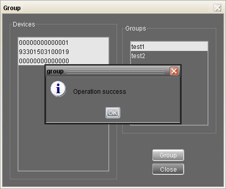
36 34
37 Delete : Remove devices from assigned group. Please select one device from assigned group and click Delete button to remove specific device from group. For example, click from test1 group and then click Delete button. Then, will be removed from test1 group. 35
38 Delete group : It s to delete group. Select device (it s ok to be blank) and then click Delete group button. It will remove the whole group. For example, click any blank from test2 and then click Delete group button. It will delete test2 group name from group list. 36

39 Clear : Clear all settings. Simply click Clear button to delete all settings in parallel charging setting page Restore to the defaults This function is allowed to restore all settings back to default value and clear all data in database. Select Device control >> Restore to the defaults. Refers to Diagram Diagram

40 4.3. View Data This function is to browse the working data of solar charge controller saved in table or chart format. Datasheets Select View >>Data>>Datasheets or click shortcut icon. Refer to Diagram Select browsed device and period to display in the screen. Click Browse to get result. Export Excel : When selected and click Export button, it will save listed table to local PC in.xls file. Export : Click Export button to save listed table to local PC in.pdf file. Delete : Select specific data and click Delete button to delete the record. Otherwise, the record can not be deleted. Delete all : Click Delete All button to delete all records in the listed table. Diagram Charts Select View >>Data>>Charts. Refer to Diagram Select browsed device and period. Then, click "Browse" to get the result. 38


41 Diagram Event log Select View >>Event log or click shortcut icon to enter event log. It's to browse history events according to time duration selected. It lists all detailed information and statistics for history events. Refer to Diagram Export Excel : When selected and click Export button, it will save listed table to local PC in.xls file. Export : Click Export button to save listed table to local PC in.pdf file. Delete : Select specific data and click Delete button to delete the record. Delete all : Click Delete All button to delete all records in the listed table. Diagram
42 4.4. Log in and Log out This short cut icon is to display the login status. When icon is displayed, it means user status is guest. When icon administrator. is displayed, it means user logins as Click icon and enter password to login the software. The default password is administrator. Refer to Diagram Diagram Click icon to log out. Then, the status will become to "guest". Refer to Diagram Diagram
43 4.5. Help About: Click Help menu and select About item. It represents the copyright information about software Help: Click Help menu and select Online help item. It will open the help manual. Before operating software, please read manual carefully. 41
User Manual MPPTracker
 User Manual MPPTracker Management Software for Solar Charge Controller Version: 1.0 Table of Contents 1. MPPTracker Overview... 1 1.1. Introduction... 1 1.2. Features... 1 2. MPPTracker Install and Uninstall...
User Manual WatchPower
 User Manual WatchPower Management Software for SP Efecto / SP Brilliant (Plus) / SP Initial Table of Contents 1. WatchPower Overview...1 1.1. Introduction... 1 1.2. Features... 1 2. WatchPower Install
User Manual PDUTracker
 User Manual PDUTracker Management Software for PDU Table of Contents 1. Overview... 1 1.1. Introduction... 1 1.2. Features... 1 2. Install and Uninstall... 1 2.1. System Requirement... 1 2.2. Software
User Manual WatchPower
 User Manual WatchPower Management Software for Inverter Table of Contents 1. WatchPower Overview... 1 1.1. Introduction... 1 1.2. Features... 1 2. WatchPower Install and Uninstall... 1 2.1. System Requirement...
User Manual SolarTracker
 User Manual SolarTracker Management Software for Inverter Table of Contents 1. SolarTracker Overview... 1 1.1. Introduction... 1 1.2. Features... 1 2. SolarTracker Install and Uninstall... 1 2.1. System
SolarPower Pro. User s Manual. Management Software for Solar Inverter
 SolarPower Pro User s Manual Management Software for Solar Inverter Table of Contents 1. SolarPower Pro Overview... 2 1.1. Introduction... 2 1.2. Structure... 2 1.3. Features... 3 2. SolarPower Pro Install
User s Manual. Management Software for Uninterruptible Power Supply Systems
 ViewPowerMini User s Manual Management Software for Uninterruptible Power Supply Systems Table of Contents 1. ViewPowerMini Overview...2 1.1. Introduction...2 1.2. Structure...3 1.3. Features...3 2. ViewPowerMini
ViewPower. User s Manual. Management Software for Uninterruptible Power Supply Systems
 ViewPower User s Manual Management Software for Uninterruptible Power Supply Systems Table of Contents 1. ViewPower Overview... 2 1.1. Introduction... 2 1.2. Structure... 2 1.3. Applications... 3 1.4.
ViewPower. User s Manual. Management Software for Uninterruptible Power Supply Systems
 ViewPower User s Manual Management Software for Uninterruptible Power Supply Systems Table of Contents 1. ViewPower Overview...2 1.1. Introduction...2 1.2. Structure...2 1.3. Applications...2 1.4. Features...3
ViewPower Pro. Software. User & Installation Manual Xtreme Power Conversion Corporation. All rights reserved.
 ViewPower Pro User & Installation Manual www.xpcc.com 2016. All rights reserved. (Rev 8/12/16) Table of Contents ViewPower Pro Overview...3 Introduction...3 Structure...3 Features...3 ViewPower Pro Install
ViewPower Pro. User s Manual. Management Software for Uninterruptible Power Supply Systems
 ViewPower Pro User s Manual Management Software for Uninterruptible Power Supply Systems Table of Contents 1. ViewPower Pro Overview... 3 1.1. Introduction... 3 1.2. Structure... 3 1.3. Features... 4 2.
Management Software for Uninterruptible Power Supply Systems
 Management Software for Uninterruptible Power Supply Systems Table of Contents 1. Forza Overview...2 1.1. Introduction...2 1.2. Structure...2 1.3. Applications...3 1.4. Features...3 2. Forza Install and
ViewPower HTML5. User Manual
 ViewPower HTML5 User Manual Management Software for Uninterruptible Power Supply Systems Table of Contents 1. ViewPower Overview... 1 1.1. Introduction... 1 1.2. Structure... 1 1.3. Applications... 1 1.4.
SNMP Manager User s Manual
 SNMP Manager User s Manual Table of Contents 1. Introduction...1 2. SNMP Manager Install, Quick Start and Uninstall...2 2.1. Software Installation...2 2.2. Software Quick Start...2 2.3. Software Uninstall...3
USER MANUAL. PowerFrame TM Personal. UPS Monitoring Software
 USER MANUAL PowerFrame TM Personal UPS Monitoring Software www.bxterra.com 1 TABLE OF CONTENTS Introduction... Structure... Applications... Features... System Requirements... Supported Operating Systems...
USER MANUAL SNMP-RC210 SNMP WEB MANAGEMENT CARD. bxterra.com
 USER MANUAL SNMP-RC210 SNMP WEB MANAGEMENT CARD bxterra.com TABLE OF CONTENTS INTRODUCTION... INSTALLATION... SNMP MANAGER GUI... SNMP MANAGER FUNCTIONS MENU... SETTINGS... ONLINE UPGRADE... SYSTEM MANAGER...
SNMP Web Manager. User s Manual
 SNMP Web Manager User s Manual Table of Contents 1. Introduction... 2 2. SNMP Web Manager Install, Quick Start and Uninstall... 2 2.1. Software Installation... 3 2.2. Software Quick Start... 6 2.3. Software
SNMP Web Management. User s Manual
 SNMP Web Management User s Manual Suitable Product: SNMP Web Card SNMP Web Box Management Software for Uninterruptible Power Supply Systems Table of Contents 1. Overview... 1 1.1 Introduction... 1 1.2
Fiery Command WorkStation 5.8 with Fiery Extended Applications 4.4
 Fiery Command WorkStation 5.8 with Fiery Extended Applications 4.4 Fiery Extended Applications (FEA) v4.4 contains Fiery software for performing tasks using a Fiery Server. This document describes how
Installation Guide Command WorkStation 5.6 with Fiery Extended Applications 4.2
 Installation Guide Command WorkStation 5.6 with Fiery Extended Applications 4.2 Fiery Extended Applications Package (FEA) v4.2 contains Fiery applications for performing tasks associated with a Fiery Server.
Contents Contents... 2 Chapter 1 Software introduction Brief introduction Software structure Application
 User Guide Contents Contents... 2 Chapter 1 Software introduction... 4 1.1 Brief introduction... 4 1.2 Software structure... 4 1.3 Application... 5 1.3.1 Application on individual computer... 5 1.3.2 Application
User Manual for Solar Station Monitor
 User Manual for Solar Station Monitor 1. Introduction As a piece of PC terminal software developed by Shenzhen Shuori New Energy Technology Co., Ltd., the software of solar station monitor can be set through
Network Management Card. User Manual
 User Manual 1 Contents Contents 2 Chapter 1 Overview 3 1.1 NMC package contents 4 1.2 NMC CD Resources 4 1.3 Features 4 1.4 NMC Applications 5 Chapter 2 NMC parameters setting via serial COM port 6 2.1
InfraSuite Device Master
 Delta Electronics, Inc. InfraSuite Device Master User s Manual Model: EMS4000 Doc. Version: v1.0 Content 1. Introduction... 5 1.1 System Architecture... 5 2. Software Installation... 7 2.1 Presentation
Network Management Card. User Manual
 User Manual 1 Contents Contents 2 Chapter 1 Overview 3 1.1 NMC package contents 4 1.2 NMC CD Resources 4 1.3 Features 4 1.4 NMC Applications 5 Chapter 2 NMC parameters setting via serial COM port 6 2.1
GIGABYTE Remote Management Console User s Guide. Version: 1.0
 GIGABYTE Remote Management Console User s Guide Version: 1.0 Table of Contents Using Your GIGABYTE Remote Management Console...2 Software Install...3 Prerequisites on remote management PC...3 Install Java
VSM Manager. The VSM Manager is a Windows GUI that can be installed to serially control Genesis Matrixes with a firmware of version 2.5 or later.
 VSM Manager Table of Contents Overview...1 Getting Started...1 Toolbar... 2 Serial Connection... 2 Refresh... 3 Help... 3 Tab Pages... 4 General... 4 Control...5 Schedule... 6 Command... 6 Communications...
Dell Repository Manager Business Client Version 2.0 User s Guide
 Dell Repository Manager Business Client Version 2.0 User s Guide Notes, Cautions, and Warnings NOTE: A NOTE indicates important information that helps you make better use of your computer. CAUTION: A CAUTION
Dell Repository Manager Business Client Version 2.1 User s Guide
 Dell Repository Manager Business Client Version 2.1 User s Guide Notes, cautions, and warnings NOTE: A NOTE indicates important information that helps you make better use of your computer. CAUTION: A CAUTION
1 Introduction to the software
 1 Introduction to the software mk:@msitstore:d:\winpower%20net\helpeng.chm::/introduction%20to%20softw... 1/2 1 Introduction to the software The monitoring software is matched with our company controller.
Dell Repository Manager Business Client Version 2.2 User s Guide
 Dell Repository Manager Business Client Version 2.2 User s Guide Notes, cautions, and warnings NOTE: A NOTE indicates important information that helps you make better use of your computer. CAUTION: A CAUTION
TouchKit Touch Panel User manual for WindowsNT4 Version: 3.1.4
 TouchKit Touch Panel User manual for WindowsNT4 Version: 3.1.4 TouchKit Touch Panel v3.1.4 0 CONTENT CHAPTER 1. TOUCH PANEL CONTROLLER...2 1.1 CONTROLLER...2 1.2 SPECIFICATIONS AND FEATURES...3 CHAPTER
TouchKit Touch Panel User manual for WindowsNT4 Version: 3.1.4
 TouchKit Touch Panel User manual for WindowsNT4 Version: 3.1.4 TouchKit Touch Panel v3.1.4 0 CONTENT CHAPTER 1. TOUCH PANEL CONTROLLER... 2 1.1 CONTROLLER... 2 1.2 SPECIFICATIONS AND FEATURES... 3 CHAPTER
Dell Network Management Card. User's Guide. w w w. d e l l. c o m s u p p o r t. d e l l. c o m
 Dell Network Management Card User's Guide w w w. d e l l. c o m s u p p o r t. d e l l. c o m Notes and Warnings NOTE: A NOTE indicates important information that helps you make better use of your software.
INDEX. Network Power Monitor R10 SNMP
 Innovative Electronics for a Changing World NPM-R10 Remote Network Power Monitor With optional relay board and GSM module INDEX Amended 21 March 2017: Add user defined Password see page 13 Add wire Connection
INDEX. Network Power Monitor NPM-R10-SNMP. Innovative Electronics for a Changing World. NPM-R10-SNMP Remote Network Power Monitor
 Innovative Electronics for a Changing World NPM-R10-SNMP Remote Network Power Monitor Optional relay board and GSM module INDEX 1. SYSTEM DESCRIPTION 2. SYSTEM BATTERY CONNECTIONS 3. SERIES CONNECTED BATTERIES
CLIQ Web Manager. User Manual. The global leader in door opening solutions V 6.1
 CLIQ Web Manager User Manual V 6.1 The global leader in door opening solutions Program version: 6.1 Document number: ST-003478 Date published: 2016-03-31 Language: en-gb Table of contents 1 Overview...9
Wireless Presentation System User s Manual
 Téléchargé depuis www.lampe-videoprojecteur.info Wireless Presentation System User s Manual Version: 1.0 Date: 2008.1.11 User s Manual 1 Table of Contents 1. Overview... 3 2. First Setup of the Wireless
USER GUIDE FOR HARLEY-DAVIDSON BOOM! BOX GTS MAP UPDATE TOOLBOX
 USER GUIDE FOR HARLEY-DAVIDSON BOOM! BOX GTS MAP UPDATE TOOLBOX Contents 1. What is Boom! Box GTS Toolbox?. Install Boom! Box GTS Toolbox.1. For Windows 4.. For Mac (OSX) 4. Navigation Data Synchronizing
NORDSON CORPORATION AMHERST, OHIO USA
 CanWorks Operator Interface Tracking PLUS for CanWorks Systems with SM-2 Spray Monitors User Guide Part 1018132A NORDSON CORPORATION AMHERST, OHIO USA 2002 Nordson Corporation. All rights reserved. CanWorks,
Online Help StruxureWare Data Center Expert
 Online Help StruxureWare Data Center Expert Version 7.2.7 What's New in StruxureWare Data Center Expert 7.2.x Learn more about the new features available in the StruxureWare Data Center Expert 7.2.x release.
Industrial Serial Device Server
 1. Quick Start Guide This quick start guide describes how to install and use the Industrial Serial Device Server. Capable of operating at temperature extremes of -10 C to +60 C, this is the Serial Device
Network Management Utility
 4343-7705-02 Network Management Utility Foreword Welcome Network Management Utility is utility software that provides central control over printers, copiers, and other devices on a network. With Network
Network Management Software ALLNET Zone Controller
 Network Management Software ALLNET Zone Controller For ALL0558N / ALL02850N / ALL02860ND / ALL02880ND User Manual v1.0 Table of Contents 1. Installation & Un-installation... 4 1.1. Install NMS Suite...
Winpower. User Manual
 Winpower User Manual Table of Contents Chapter 1 Winpower Introduction... 4 1. Winpower profile... 4 2. Winpower Structure... 4 3. Winpower Application Range... 5 4. Winpower Functions & Advantages...
Version /20/2012. User Manual. AP Manager II Lite Business Class Networking
 Version 1.0 12/20/2012 User Manual AP Manager II Lite Business Class Networking Table of Contents Table of Contents Product Overview... 1 Minimum System Requirements... 2 Access Point Requirements... 2
Contents Contents Brief introduction Software structure Application Application on individual computer...
 User Guide Contents Contents... 2 1.1 Brief introduction... 4 1.2 Software structure... 4 1.3 Application... 5 1.3.1 Application on individual computer... 5 1.3.2 Application in the LAN/WAN/Internet...
NET101. RS232 / RS422 / RS485 to Ethernet Converter. User s Manual. Version 1.2
 NET101 RS232 / RS422 / RS485 to Ethernet Converter User s Manual Version 1.2 Copyright Information Copyright 2004-2005, Mega System Technologies, Inc. All rights reserved. Reproduction without permission
Standalone DVR User s Manual. Figure 4-81
 Figure 4-81 4.11.2 Network 4.11.2.1 TCP/IP The single network adapter interface is shown as in Figure 4-82 and the dual network adapters interface is shown as in Figure 4-83 Network Mode : Includes multiple
RS-1260 Digital Signage Player
 RS-1260 Digital Signage Player User Manual V1.3 Legal Notice and Disclaimer Thank you for choosing RapidSignage products. This user manual provides a description of the Player relevant guidelines for key
NVMS User Manual
 NVMS-1000 User Manual Contents 1 Software Introduction...1 1.1 Summary... 1 1.2 Operation Environment... 1 1.3 Install and Uninstall... 2 1.3.1 Install the Software... 2 1.3.2 Uninstall the Software...
Air-conditioner Control System Centralized Controller AG-150A AG-150A-A GB-50ADA-J
 Air-conditioner Control System Centralized Controller AG-150A AG-150A-A GB-50ADA-A GB-50ADA-J Instruction Book (Web browser for optional functions) Contents 1 Introduction... 1 1-1 Terms Used in This Manual...
(B) Execute SMS TCP MODBUS Interface Application
 Execute SMS TCP MODBUS Interface Application") Security Management System software generates notifications which indicate the state of various health parameters eg disk failure, one or more cameras offline etc. These notifications can be exposed as
Security Management System software generates notifications which indicate the state of various health parameters eg disk failure, one or more cameras offline etc. These notifications can be exposed as
IP Device Search and Configuration Tool Operation Manual
 IP Device Search and Configuration Tool Operation Manual Note Copyright Statement This manual may not be reproduced in any form or by any means used to create any derivative such as translation, transformation,
TouchKit TouchScreen Controller User Manual for Windows NT4 Version: 3.4.0
 TouchKit TouchScreen Controller User Manual for Windows NT4 Version: 3.4.0 1 CONTENT CHAPTER 1. TOUCH PANEL CONTROLLER 2 1.1 Controller 2 1.2 Specifications and Features 3 CHAPTER 2. INSTALLING TOUCHKIT
WS-QL Series User Manual
 35011181 ver.01 1-01 C10-015 WS-QL Series User Manual Contents Chapter 1 Opening Windows Storage Server... 3 Opening Windows Storage Server...3 Chapter Windows Update... 4 Windows Update...4 Chapter 3
Centralized Controller AG-150A GB-50ADA-A GB-50ADA-J
 Air-conditioner Network System Centralized Controller AG-150A GB-50ADA-A GB-50ADA-J Instruction Book (Web browser for optional functions) Contents 1 Introduction...1 1-1 Terms Used in This Manual... 1
DBT-120 Bluetooth USB Adapter
 DBT-120 Bluetooth USB Adapter Rev.2.1 (09/25/2002) 2 Contents Introduction... 5 Package Contents... 6 Installing Bluetooth Software... 6 Hardware Installation... 8 Introduction to Bluetooth Software...
TouchKit TouchScreen Controller User Guide for Windows NT4 Version: 3.2.1
 TouchKit TouchScreen Controller User Guide for Windows NT4 Version: 3.2.1 TouchKit Guide for WinNT4 v3.2.1 0 CONTENT CHAPTER 1. TOUCH PANEL CONTROLLER... 2 1.1 CONTROLLER... 2 1.2 SPECIFICATIONS AND FEATURES...
Innovative Electronics for a Changing World INDEX
 Innovative Electronics for a Changing World INDEX 1. SYSTEM DESCRIPTION 2. BOARD CONNECTIONS terminals and indicators 3. CONNECTION DIAGRAM 4. START UP GUIDE and passwords 5. HOME PAGE 6. STATUS PAGE 7.
Network USB over IP Server With 1-USB2.0 Port. User Manual V1.0
 Network USB over IP Server With 1-USB2.0 Port User Manual V1.0 1 2 TABLE OF CONTENTS COPYRIGHT...4 1. INTRODUCTION...5 PRODUCT OVERVIEW...5 COMPONENTS AND FEATURES...5 HARDWARE INSTALLATION...5 2. THE
EnGenius Mesh AP Reset Tool Quick Guide
 EnGenius Mesh AP Reset Tool Quick Guide Revision : 1.1 Table of Contents EnGenius MESH AP Reset Tool Quick Guide 1. Overview...3 2. Installation Procedure...3 3. Uninstallation Procedure...3 4. Tool Layout...4
Epson Device Admin User s Guide NPD EN
 Epson Device Admin User s Guide NPD5817-00 EN About this Manual About this Manual Marks and Symbols! Caution: Instructions that must be followed carefully to avoid bodily injury. c Important: Instructions
Decoder Firmware B1D-220-V AC User s Manual Decoder Firmware B1D-220-V AC User s Manual
 Decoder Firmware B1D-220-V3.03.07-AC User s Manual i Table of Contents INTRODUCTION 1 1.1 Minimum system requirements 1 1.2 Preparation before setup 2 1.2.1 Setup your PC network 2 1.3 Configuring the
Legal Notes. Regarding Trademarks KYOCERA Document Solutions Inc.
 Legal Notes Unauthorized reproduction of all or part of this guide is prohibited. The information in this guide is subject to change without notice. We cannot be held liable for any problems arising from
ShineNet. Growatt Version Date Notes New. ShineNet V1.0
 ShineNet Growatt 1.0 2012-09-25 Version Date Notes 1.0.0.2 2012-09-25 New Table of Contents 1. Introduction...3 2. Install and Uninstall...4 2.1 System requirements...4 2.2 Install software...4 2.3 Uninstall
User Guide NAS 3.0 Adapter (NAS30U2)
") T E C H N O L O G I E S User Guide NAS 3.0 Adapter (NAS30U2) www.addonics.com v5.1.11 Technical Support If you need any assistance to get your unit functioning properly, please have your product information
T E C H N O L O G I E S User Guide NAS 3.0 Adapter (NAS30U2) www.addonics.com v5.1.11 Technical Support If you need any assistance to get your unit functioning properly, please have your product information
Kaseya 2. Quick Start Guide. for Network Monitor 4.1
 Kaseya 2 Router Monitor Quick Start Guide for Network Monitor 4.1 June 5, 2012 About Kaseya Kaseya is a global provider of IT automation software for IT Solution Providers and Public and Private Sector
Operation. Symmetra MW II. Parallel System with Internal Bypass Static Switch. Normal Normal. UPS Summary. X405 UPS Summary.
 X008B X010 X007 X021 X022 X012 X008A X014A X011 X405 X013 X017 X014B UPS Summary UPS Summary ~ ~ ~ ~ Normal Normal Normal Normal Operation Symmetra MW II Parallel System with Internal Bypass Static Switch
LE840/LE850. Printer Setting Tool Manual Technical Reference
 LE840/LE850 Printer Setting Tool Manual Technical Reference Table of Contents 1. INTRODUCTION 1 SUPPORTED PRINTERS... 1 FEATURES... 1 OUTLINE OF THE FUNCTIONS... 2 NOTATION... 2 SCREENS USED IN THIS DOCUMENT...
User Manual. Consumer OneClick Internet. for Gobi Sierra Version st May 2010
 User Manual Consumer OneClick Internet for Gobi 2000 Sierra Version 1.8 21 st May 2010 WebToGo Mobiles Internet GmbH 81371 München, Oberländerstr. 2a Table of Content 1. General 2. Starting OneClick Connection
Winpower. User Manual
 Winpower User Manual Table of Contents Chapter 1 Winpower Introduction ----------------------------------------------------- 4 1. Winpower profile... 4 2. Winpower Structure... 4 3. Winpower Application
Version 4.1 June Xerox Device Agent (XDA) Lite User Guide
 Lite User Guide") Version 4.1 June 2013 Xerox Device Agent (XDA) Lite User Guide 2008-2013 Xerox Corporation. All rights reserved. Xerox and Xerox and Design are trademarks of Xerox Corporation in the US and/or other countries.
Version 4.1 June 2013 Xerox Device Agent (XDA) Lite User Guide 2008-2013 Xerox Corporation. All rights reserved. Xerox and Xerox and Design are trademarks of Xerox Corporation in the US and/or other countries.
Apptix Online Backup by Mozy User Guide
 Apptix Online Backup by Mozy User Guide 1.10.1.2 Contents Chapter 1: Overview...5 Chapter 2: Installing Apptix Online Backup by Mozy...7 Downloading the Apptix Online Backup by Mozy Client...7 Installing
NVMS1000. User Manual
 NVMS1000 User Manual Contents 1 Software Introduction... 1 1.1 Summary... 1 1.2 Operation Environment... 1 1.3 Install and Uninstall... 2 1.3.1 Install the Software... 2 1.3.2 Uninstall the Software...
Kaseya 2. Quick Start Guide. for Network Monitor 4.1
 Kaseya 2 IIS Monitor Quick Start Guide for Network Monitor 4.1 June 5, 2012 About Kaseya Kaseya is a global provider of IT automation software for IT Solution Providers and Public and Private Sector IT
AP-ENBD User Manual V0.2
 AP-ENBD User Manual V0.2 2015/12 Catolog Catolog... 2 1 Introduction... 1 1.1 Communication Structure... 1 1.2 Internal Principle... 2 2 Installation... 2 2.1 Connect to the Same Router (or Switch )...
KMnet Viewer. User Guide
 KMnet Viewer User Guide Legal Notes Unauthorized reproduction of all or part of this guide is prohibited. The information in this guide is subject to change for improvement without notice. We cannot be
HP Video Over Ethernet. User Guide
 HP Video Over Ethernet User Guide 2016 HP Development Company, L.P. The information contained herein is subject to change without notice. The only warranties for HP products and services are set forth
Filr 3.3 Desktop Application Guide for Linux. December 2017
 Filr 3.3 Desktop Application Guide for Linux December 2017 Legal Notice For information about legal notices, trademarks, disclaimers, warranties, export and other use restrictions, U.S. Government rights,
LE840/LE850. Network Tool Manual Technical Reference
 LE840/LE850 Network Tool Manual Technical Reference Table of Contents INTRODUCTION 1 SUPPORTED PRINTERS... 1 FEATURES... 1 NOTATION... 1 USAGE LIMITATION OF THE PRODUCT... 2 SCREENS USED IN THIS DOCUMENT...
UNIVERSAL SOFTWARE. Universal Software. Data Sheet
 Universal Software Data Sheet System Requirements: The minimum requirements for using the Software are: 1). Windows XP/Vista/7 2). A minimum of 512 MB RAM 3). 1 GB of hard disk space 4). Microsoft Office
NVMS User Manual
 NVMS-1000 User Manual Contents 1 Software Introduction...1 1.1 Summary... 1 1.2 Operation Environment... 1 1.3 Install and Uninstall... 2 1.3.1 Install the Software... 2 1.3.2 Uninstall the Software...
NETWORK PRINT MONITOR User Guide
 NETWORK PRINT MONITOR User Guide Legal Notes Unauthorized reproduction of all or part of this guide is prohibited. The information in this guide is subject to change for improvement without notice. We
BACKUP APP V7 QUICK START GUIDE FOR SYNOLOGY NAS
 BACKUP APP V7 QUICK START GUIDE FOR SYNOLOGY NAS Revision History Date Descriptions Type of modification 29 Jun 2016 First Draft New 25 Nov 2016 Modified Ch 3 Download Backup App, Ch 3 Install Backup App
Industrial Ethernet Products Management Utility
 Industrial Ethernet Products Management Utility Open-Vision User s Manual Version 1.1 April, 2013 ORing Industrial Networking Corp. 3F.,NO.542-2, Jhong-Jheng Rd.Sindian District, New Taipei City 23148
TouchKit Touch Panel User manual for Windows9X/ME Version: 3.1.4
 TouchKit Touch Panel User manual for Windows9X/ME Version: 3.1.4 TouchKit Touch Panel v3.1.4 0 CONTENT CHAPTER 1. TOUCH PANEL CONTROLLER... 2 1.1 CONTROLLER... 2 1.2 SPECIFICATIONS AND FEATURES... 3 CHAPTER
WSDA User Guide
 User Guide Version 8500-0029 rev. 006 WSDA -1000 User Guide www.microstrain.com Little Sensors, Big Ideas. 2012 by 459 Hurricane Lane, Suite 102 Williston, VT 05495 Phone 802-862-6629 Fax 802-863-4093
DMS Local. User Manual. For Projector Management V 1.01
 DMS Local User Manual For Projector Management V 1.01 2 Copyright Copyright Copyright 2018 BenQ Corporation. All rights reserved. No part of this publication may be reproduced, transmitted, transcribed,
10ZiG Technology. Thin Desktop Quick Start Guide
 10ZiG Technology Thin Desktop Quick Start Guide 2010 05 20 Introduction This document is intended as a quick start guide for installing Thin Desktop. After reading this document, you will know how to:
ModeChanger
 35020808-02 2015.11 ModeChanger ModeChanger is a software utility that can switch the drive between normal mode and encrypted mode. Operating in encrypted mode will help protect your data. While the drive
INTERFACE & 16 YUUWAA ONLINE SERVICES...
 USER GUIDE Table of Contents INTRODUCTION... 3 SYSTEM REQUIREMENTS... 4 YUUWAA BACKUP... 5 Set Up Your First Backup... 5 Create Your Backup... 6 YuuWaa Online Backup... 9 Launch Your Backup... 11 YuuWaa
TouchScreen for Display & Panel-PC
 TouchScreen for Display & PanelPC User Manual for Windows 2000 / XP Version: 4.0.2 TouchKit Manual for Win2000/XP v4.0.2 Page 1 CONTENT CHAPTER 1. TOUCH PANEL CONTROLLER... 3 1.1 CONTROLLER... 3 1.2 SPECIFICATIONS
TOWERRAID TR4UTBPN. RAID MONITORING GUIDE v1.0
 TOWERRAID TR4UTBPN RAID MONITORING GUIDE v1.0 Copyright Sans Digital 2009~2010. All rights reserved. No part of this publication may be reproduced, transmitted, transcribed or translated into any language
IT Essentials v6.0 Windows 10 Software Labs
 IT Essentials v6.0 Windows 10 Software Labs 5.2.1.7 Install Windows 10... 1 5.2.1.10 Check for Updates in Windows 10... 10 5.2.4.7 Create a Partition in Windows 10... 16 6.1.1.5 Task Manager in Windows
TABLE OF CONTENTS COPYRIGHT INTRODUCTION...3 PRODUCT OVERVIEW...3 COMPONENTS AND FEATURES...3 HARDWARE INSTALLATION
 TABLE OF CONTENTS COPYRIGHT...2 1. INTRODUCTION...3 PRODUCT OVERVIEW...3 COMPONENTS AND FEATURES...3 HARDWARE INSTALLATION...3 2. MFP SERVER INSTALLATION...5 PREPARATION...5 CONFIGURATION SOLUTION TABLE...5
User s Guide AIR-USB112NH November, VRTL8191SU
 AIRNET 300Mb 802.11b/g/n High Power USB Adapter User s Guide AIR-USB112NH November, 2010 - VRTL8191SU TABLE OF CONTENTS Installation 3 Uninstall 6 Making a Basic Network Connection 8 Ad-Hoc Mode 9 Infrastructure
Installation and Configuration User's Guide
 Dell UPS Upgrade Software Utility Installation and Configuration User's Guide w w w. d e l l. c o m s u p p o r t. d e l l. c o m Notes and Warnings NOTE: A NOTE indicates important information that helps
Contents Contents... 2 Chapter 1 Software introduction Brief introduction Software structure Application
 User Guide Contents Contents... 2 Chapter 1 Software introduction... 4 1.1 Brief introduction... 4 1.2 Software structure... 4 1.3 Application... 5 1.3.1 Application on individual computer... 5 1.3.2 Application
KYOCERA Net Viewer User Guide
 KYOCERA Net Viewer User Guide Legal Notes Unauthorized reproduction of all or part of this guide is prohibited. The information in this guide is subject to change without notice. We cannot be held liable