Network Video Recorder User s Manual
|
|
|
- Carmel Blankenship
- 6 years ago
- Views:
Transcription

1 Network Video Recorder User s Manual V1.0.1 i
2 Table of Contents 1 Features and Specifications Overview Features Specifications N44PS N48PS N461X Front Panel and Rear Panel Front Panel N44PS\N48PS N461X Rear Panel N44PS N48PS N461X Device Installation Check Unpacked NVR About Front Panel and Rear Panel HDD Installation Mini 1U/Compact 1U Series Local Basic Operation Boot up and Shutdown Boot up Shutdown Change/Reset Password Change Password Startup Wizard Navigation Bar Main Menu Dual-screen operation Output Screen Tour PTZ Color Search Alarm Status Channel Info Remote Device Network HDD Manager USB Manager Remote Device Remote Device Connection ii
3 4.5.2 Short-Cut Menu Image Channel Name Upgrade UPNP Built-in Switch Setup Preview Preview Preview control interface Right Click Menu Preview Display Effect Setup Video Color Display Preview Tour Parameters PTZ Control PTZ Function Setup Call PTZ Function Record and Snapshot Encode Encode Overlay Snapshot Schedule Schedule Record Schedule Snapshot Motion detect record/snapshot Motion detect record Motion Detect Snapshot Alarm Record/Snapshot Alarm Record Alarm Snapshot Manual Record/Snapshot Manual Record Manual Snapshot Holiday Record/Snapshot Holiday Record Holiday Snapshot Playback and Search Search Interface Smart Search Accurate playback by time I Mark Playback Picture Playback Backup File Backup iii
4 4.9.2 Import/Export Backup Log USB Device Auto Pop-up Alarm Detect Alarm Motion Detect Tampering Video Loss Alarm output Alarm Setup Abnormality Network TCP/IP Connection WIFI G PPPoE DDNS UPnP IP Filter FTP SNMP Multicast P2P Cloud Storage SWITCH Network Test Network Test Network Load HDD Setup Format HDD Information Advanced Basic Setups Device Setup Data and Time Holiday Device Maintenance and Manager System Info Version BPS Online User Remote Device Information Remote Device Status iv
5 Firmware Log Account Add User Modify user Change Password Add/Modify Group Update Local Update Uboot Default Auto Maintain Logout /Shutdown/Restart Web Operation General Introduction Preparation Log in LAN Mode Real-time Monitor PTZ Image/Alarm-out Image Alarm output Zero-channel Encode WAN Login Setup Camera Remote Device Image Encode Encode Snapshot Video Overlay Path Channel Name IPC Upgrade Network TCP/IP Connection WIFI AP WIFI G CDMA/GPRS Mobile PPPoE DDNS v
6 IP filter UPnP SNMP Multicast Auto Register Alarm Centre HTTPS Create Server Certificate Download root certificate View and set HTTPS port Login P2P Event Video detect Motion Detect Video Loss Tampering IVS (Optional) Tripwire Intrusion (Cross warning zone) Object Detect Change Scene Face Detect (Optional) Audio Detect (Optional) Alarm Local Alarm Net Alarm IPC external alarm IPC Offline Alarm Abnormality Storage Schedule HDD Manager Local Storage HDD FTP Record Control RAID Manager RAID Config Hotspare disks Storage Main Stream Sub Stream Snapshot Setting vi
7 General General Date and time Holiday Setup Account User name Group Display Display Tour Alarm Out Default Import/Export Auto maintain Upgrade RS PTZ Information Version Log Online User Playback Search Record File List Playback Download Load more Download By File Download by Time Watermark Alarm Log out Un-install Web Control Glossary FAQ Appendix A HDD Capacity Calculation Appendix B Compatible Network Camera List vii
8 Welcome Thank you for purchasing our network video recorder! This user s manual is designed to be a reference tool for your system. Please open the accessory bag to check the items one by one in accordance with the list below. Contact your local retailer ASAP if something is missing or damaged in the bag. viii
9 Important Safeguards and Warnings 1.Electrical safety All installation and operation here should conform to your local electrical safety codes. The product must be grounded to reduce the risk of electric shock. We assume no liability or responsibility for all the fires or electric shock caused by improper handling or installation. 2.Transportation security Heavy stress, violent vibration or water splash are not allowed during transportation, storage and installation. 3.Installation Keep upwards. Handle with care. Do not apply power to the NVR before completing installation. Do not place objects on the NVR. 4.Qualified engineers needed All the examination and repair work should be done by the qualified service engineers. We are not liable for any problems caused by unauthorized modifications or attempted repair. 5.Environment The NVR should be installed in a cool, dry place away from direct sunlight, inflammable, explosive substances and etc. This series product shall be transported, storage and used in the specified environments. Environment which needs to comply with the following conditions: The function of the ITE being investigated to IEC is considered not likely to require connection to an Ethernet network with outside plant routing, including campus environment. The installation instructions clearly state that the ITE is to be connected only to PoE networks without routing to the outside plant. 6. Accessories Be sure to use all the accessories recommended by manufacturer. Before installation, please open the package and check all the components are included. Contact your local retailer ASAP if something is broken in your package. 7. Lithium battery Improper battery use may result in fire, explosion, or personal injury! When replace the battery, please make sure you are using the same model! CAUTION RISK OF EXPLOSION IF BATTERY IS REPLACED BY AN INCORRECT TYPE. DISPOSE OF USED BATTERIES ACCORDING TO THE INSTRUCTIONS. Before your operation please read the following instructions carefully. Installation environment ix
10 Keep away from extreme hot places and sources; Avoid direct sunlight; Keep away from extreme humid places; Avoid violent vibration; Do not put other devices on the top of the NVR; Be installed in well ventilated place; do not block the vent. Accessories Check the following accessories after opening the box: Please refer to the packing list in the box * x
11 1 Features and Specifications 1.1 Overview This series NVR is a high performance network video recorder. This series product support local preview, multiple-window display, recorded file local storage, remote control and mouse shortcut menu operation, and remote management and control function. This series product supports centre storage, front-end storage and client-end storage. The monitor zone in the front-end can be set in anywhere. Working with other front-end devices such as IPC, NVS, this series product can establish a strong surveillance network via the CMS. In the network system, there is only one network cable from the monitor centre to the monitor zone in the whole network. There is no audio/video cable from the monitor centre to the monitor zone. The whole project is featuring of simple connection, low-cost, low maintenance work. This series NVR can be widely used in many areas such as public security, water conservancy, transportation and education. 1.2 Features Real-time Surveillance Playback User Management Storage Alarm VGA, HDMI port. Connect to monitor to realize real-time surveillance. Some series support TV/VGA/HDMI output at the same time. Short-cut menu when preview. Support popular PTZ decoder control protocols. Support preset, tour and pattern. Support each channel real-time record independently, and at the same time it can support search, forward play, network monitor, record search, download and etc. Support various playback modes: slow play, fast play, backward play and frame by frame play. Support time title overlay so that you can view event accurate occurred time Support specified zone enlargement. Each group has different management powers that can be edited freely. Every user belongs to an exclusive group. Via corresponding setup (such as alarm setup and schedule setup), you can backup related audio/video data in the network video recorder. Support Web record and record local video and storage the file in the client end. Respond to external alarm simultaneously (within 200MS), based on user s pre-defined relay setup, system can process the alarm input correctly and prompt user by screen and voice (support pre-recorded audio). Support central alarm server setup, so that alarm information can remotely notify user automatically. Alarm input can be derived from various connected peripheral devices. Alert you via /sms. 1
12 Network Monitor Through network, sending audio/video data compressed by IPC or NVS to client-ends, then the data will be decompressed and display.. Transmit audio/video data by HTTP, TCP, UDP, MULTICAST, RTP/RTCP and etc. Transmit some alarm data or alarm info by SNMP. Support WEB access in WAN/LAN. Window Split Record Backup Network Management Peripheral Equipment Management Auxiliary Adopt the video compression and digital process to show several windows in one monitor. Support 1/4/8/9/16/ 25/36-window display when preview and 1/4/9/16-window display when playback. Support normal/motion detect/alarm record function. Save the recorded files in the HDD, USB device, client-end PC, or network storage server. You can search or playback the saved files at the local-end or via the Web/USB device. Support network backup, USB2.0 record backup function, the recorded files can be saved in network storage server, peripheral USB2.0 device, burner and etc. Supervise NVR configuration and control power via Ethernet. Support management via WEB. Support peripheral equipment management such as protocol setup and port connection. Support transparent data transmission such as RS232 (RS-422), RS485 (RS-485). Support switch between NTSC and PAL. Support real-time system resources information and running statistics display. Support log file. Local GUI output. Shortcut menu operation via mouse. IR control function (For some series product only.). Shortcut menu operation via remote control. Support IPC or NVS remote video preview and control. 1.3 Specifications N44PS Model N44PS System Main Processor Dual-core embedded processor Operating System Embedded LINUX Video& Audio IP Camera Input 4 channel Two-way Talk 1channel Input, 1channel Output, RCA Display Interface 1 HDMI,1 VGA Resolution , , , Display Split 1/4 OSD Camera title, Time, Video loss, Camera lock, Motion detection, Recording 2
13 Recording Compression H.264/MJPEG Resolution 5Mp( )/3Mp( )/1080P( )/720P( )/D1 ( / ) Record Rate 80Mbps Bit Rate 48~ 8192kbps Record Mode Manual, Schedule(Regular(Continuous), MD, Alarm), Stop Record Interval 1~120 min (default: 60 min), Pre-record: 1~30 sec, Post-record: 10~300 sec Video Detection Trigger Events Recording, PTZ, Tour, Alarm, Video Push, , FTP, Snapshot, Buzzer & Screen tips Video Detection Motion Detection, MD Zones: 396(22 18), Video Loss & Camera Blank Playback & Backup Sync Playback 1/4 Search Mode Time/Date, Alarm, MD & Exact search (accurate to second), Smart search Playback Function Play, Pause, Stop, Rewind, Fast play, Slow play, Next file, Previous file, Next camera, Previous camera, Full screen, Repeat, Shuffle, Backup selection, Digital zoom Backup Mode USB Device/Network/Internal SATA burner Network Ethernet 1 RJ-45 port (10/100Mbps) PoE 4 ports (IEEE802.3at/af) HTTP, TCP/IP, IPv4/IPv6, UPNP, RTSP, UDP, SMTP, NTP, DHCP, DNS, IP Filter, Network Function PPPOE, DDNS, FTP, Alarm Server, IP Search(Support Dahua IP camera, DVR, NVS and etc.) Max. User Access 128 users Smart Phone iphone, ipad, Android, Windows Phone Storage Internal HDD 1 SATA port, up to 6TB Auxiliary Interface USB 2 ports,usb2.0 General Power Supply Power Consumption Working Environment Dimension (W D H) Weight Single, DC48V/1.5A NVR: 10W(without HDD) PoE: Max 25.5W for single port -10 C~+55 C / 10%~90%RH / 86~106kpa Mini 1U, 325mm 250mm 55mm 1.25KG(without HDD) 3
14 1.3.2 N48PS Model N48PS System Main Processor Dual-core embedded processor Operating System Embedded LINUX Video& Audio IP Camera Input 8 channel Two-way Talk 1 channel Input, 1 channel Output, RCA Display Interface 1 HDMI, 1 VGA Resolution , , , Display Split 1/4/8/9 OSD Camera title, Time, Video loss, Camera lock, Motion detection, Recording Recording Compression H.264/MJPEG Resolution 5Mp( )/3Mp( )/1080P( )/720P( )/D1 ( / ) Record Rate 80Mbps Bit Rate 48~ 8192kbps Record Mode Manual, Schedule(Regular(Continuous), MD, Alarm), Stop Record Interval 1~120 min (default: 60 min), Pre-record: 1~30 sec, Post-record: 10~300 sec Video Detection & Alarm Trigger Events Recording, PTZ, Tour, Alarm, Video Push, , FTP, Snapshot, Buzzer & Screen tips Video Detection Motion Detection, MD Zones: 396(22 18), Video Loss & Camera Blank Alarm Input 2 channel Relay Output 1 channel Playback & Backup Sync Playback 1/4/9 Search Mode Time/Date, Alarm, MD & Exact search (accurate to second), Smart search Playback Function Play, Pause, Stop, Rewind, Fast play, Slow play, Next file, Previous file, Next camera, Previous camera, Full screen, Repeat, Shuffle, Backup selection, Digital zoom Backup Mode USB Device/Network/Internal SATA burner Network Ethernet 1 RJ-45 port (10/100Mbps) PoE 8 ports (IEEE802.3af/at) Network Function HTTP, TCP/IP, IPv4/IPv6, UPNP, RTSP, UDP, SMTP, NTP, DHCP, DNS, IP Filter, PPPOE, DDNS, FTP, Alarm Server, IP Search(Support Dahua IP camera, DVR, NVS and etc.) Max. User Access 128 users Smart Phone iphone, ipad, Android, Windows Phone 4
15 Storage Internal HDD 1 SATA port, up to 6TB Auxiliary Interface USB 2 ports, USB2.0 General Power Supply Power Consumption Working Environment Dimension (W D H) Weight Single, DC48V/2A NVR: 10W(without HDD) PoE:Max.25.5W (for one port) -10 C~+55 C / 10%~90%RH / 86~106kpa Mini 1U, 325mm 250mm 55mm 1.25KG (without HDD) N461X Model N461X System Main Processor Dual-core embedded processor Operating System Embedded LINUX Video& Audio IP Camera Input 16 channel Two-way Talk 1 channel Input, 1 channel Output, RCA Display Interface 1 HDMI, 1 VGA Resolution , , , Display Split 1/4/8/9/16 OSD Camera title, Time, Video loss, Camera lock, Motion detection, Recording Recording Compression H.264/MJPEG Resolution 5Mp( )/4Mp( )/3Mp( )/1080P( )/ 720P( )/D1 ( / ) Record Rate 200Mbps Bit Rate 48~ 8192kbps Record Mode Manual, Schedule(Regular(Continuous), MD, Alarm), Stop Record Interval 1~120 min (default: 60 min), Pre-record: 1~30 sec, Post-record: 10~300 sec Video Detection & Alarm Trigger Events Recording, PTZ, Tour, Alarm, Video Push, , FTP, Snapshot, Buzzer & Screen tips Video Detection Motion Detection, MD Zones: 396(22 18), Video Loss & Camera Blank Alarm Input 4 channel 5
16 Relay Output 2 channel Playback & Backup Sync Playback 1/4/9/16 Search Mode Time/Date, Alarm, MD & Exact search (accurate to second), Smart search Playback Function Play, Pause, Stop, Rewind, Fast play, Slow play, Next file, Previous file, Next camera, Previous camera, Full screen, Repeat, Shuffle, Backup selection, Digital zoom Backup Mode USB Device/Network/Internal SATA burner Network Ethernet 1 RJ-45 port (10/100/1000Mbps) PoE 16 ports (IEEE802.3at/af) HTTP, TCP/IP, IPv4/IPv6, UPNP, RTSP, UDP, SMTP, NTP, DHCP, DNS, IP Filter, Network Function PPPOE, DDNS, FTP, Alarm Server, IP Search(Support Dahua IP camera, DVR, NVS and etc.) Max. User Access 128 users Smart Phone iphone, ipad, Android Storage Internal HDD 2 SATA ports, up to 8TB Auxiliary Interface USB 2 ports (1 Rear USB3.0,1 Front USB2.0) RS232 1 port, For PC communication&keyboard General Power Supply Single, AC 100~240V, 47/63 Hz Power Consumption NVR: <30W(without HDD) PoE: Max 25.5W for single port, 130W in total Working Environment -10 C~+55 C / 10%~90%RH / 86~106kpa Dimension (W D H) 1U, 375mm 327mm 53mm Weight2 2.5KG(without HDD) 6
17 2 Front Panel and Rear Panel 2.1 Front Panel N44PS\N48PS The front panel is shown as in Figure 2-1. Figure 2-1 Please refer to the following sheet for detailed information. Icon Name Function Power button Power button, press this button for three seconds to boot up or shut down NVR. NET Network status The red light becomes on when the network indicator light connection is abnormal. POWR Power indicator The red light becomes on when the power light connection is OK. HDD HDD status indictor light The red light becomes on when HDD is abnormal. ALARM Alarm indicator light The light becomes on when an alarm occurred. Up/Down Activate current control, modify setup, and then move up and down. Increase/decrease numeral. Assistant function such as PTZ menu. Left/Right ESC ESC Shift current activated control, When playback, click these buttons to control playback bar. Go to previous menu, or cancel current operation. When playback, click it to restore real-time monitor mode. ENTER Enter Confirm current operation Go to default button Go to menu 7
18 Icon Name Function One-window monitor mode, click this button to display assistant function: PTZ control and image color. Fn Assistant Backspace function: in numeral control or text control, press it for 1.5seconds to delete the previous character before the cursor. In motion detection setup, working with Fn and direction keys to realize setup. USB2.0 port In text mode, click it to switch between numeral, English character(small/capitalized) and etc. Realize other special functions. USB2.0 port. Connect to mouse, USB storage device, USB burner and etc N461X The front panel is shown as in Figure 2-2. Figure 2-2 Please refer to the following sheet for detailed information. Icon Name Function Power button Power button, press this button for three seconds to boot up or shut down NVR. NET Network status The red light becomes on when the network indicator light connection is abnormal. PWR Power indicator The red light becomes on when the power light connection is OK. HDD HDD status indictor light The red light becomes on when HDD is abnormal. ALARM Alarm indicator light The light becomes on when an alarm occurred. 8
19 Icon Name Function Up/Down Activate current control, modify setup, and then move up and down. Increase/decrease numeral. Assistant function such as PTZ menu. Left/Right ESC ESC Shift current activated control, When playback, click these buttons to control playback bar. Go to previous menu, or cancel current operation. When playback, click it to restore real-time monitor mode. ENTER Shift REC Enter Shift Record Confirm current operation Go to default button Go to menu In textbox, click this button to switch between numeral, English(Small/Capitalized),donation and etc. Manually stop/start recording, working with direction keys or numeral keys to select the recording channel. One-window monitor mode, click this button to display assistant function: PTZ control and image color. Fn Assistant Backspace function: in numeral control or text control, press it for 1.5seconds to delete the previous character before the cursor. In motion detection setup, working with Fn and direction keys to realize setup. USB2.0 port In text mode, click it to switch between numeral, English character(small/capitalized) and etc. Realize other special functions. USB2.0 port. Connect to mouse, USB storage device, USB burner and etc. 9
20 Icon Name Function Various fast speeds and normal playback. Fast play/7 In text mode, input number 7 (English character P/Q/R/S). In playback mode, playback the previous Play previous/0 video In text mode, input number 0. In normal playback or pause mode, click this button to reverse playback Reverse/Pause/6 In reverse playback, click this button to pause playback. In text mode, input number 6 (English character M/N/O). In playback mode, playback the next video In menu setup, go to down ward of the Play Next/9 dropdown list. In text mode, input number 9 (English character W/X/Y/Z). In normal playback click this button to pause playback Play/Pause /5 In pause mode, click this button to resume playback. In text mode, input number 5(English character J/K/L). Multiple slow play speeds or normal playback. Slow play/8 In text mode, input number 8 (English character T/U/V). 2.2 Rear Panel N44PS The smart box series NVR rear panel is shown as below. See Figure 2-. Figure

21 Please refer to the following sheet for detailed information. Port Name Connection Function HDMI VGA USB2.0 port Network port High Definition Media Interface VGA video output port GND USB2.0 port. Connect to mouse, USB storage device, USB burner and etc. 10M/100Mbps self-adaptive Ethernet port. Connect to the network cable. High definition audio and video signal output port. It transmits uncompressed high definition video and multiple-channel data to the HDMI port of the display device. HDMI version is 1.4. VGA video output port. Output analog video signal. It can connect to the monitor to view analog video. Ground end Power input port Input DC 48V. MIC IN Audio input port Bidirectional talk input port. It is to receive the analog audio signal output from the devices such as mike phone, pickup. MIC OUT POE PORTS Audio output port POE ports Audio output port. It is to output the analog audio signal to the devices such as the sound box. Bidirectional talk output. Audio output on 1-window video monitor. Audio output on 1-window video playback. Built-in switch. Support PoE function. For PoE series product, you can use this port to provide power to the network camera N48PS The smart box with 1 PoE port series rear panel is shown as below. See Figure 2-. Figure
22 Please refer to the following sheet for detailed information. Port Name Connection Function HDMI VGA USB2.0 port Network port High Definition Media Interface VGA video output port GND USB2.0 port. Connect to mouse, USB storage device, USB burner and etc. 10M/100Mbps self-adaptive Ethernet port. Connect to the network cable. High definition audio and video signal output port. It transmits uncompressed high definition video and multiple-channel data to the HDMI port of the display device. HDMI version is 1.4. VGA video output port. Output analog video signal. It can connect to the monitor to view analog video. Ground end Power input port Input DC 48V. MIC IN Audio input port Bidirectional talk input port. It is to receive the analog audio signal output from the devices such as mike phone, pickup. MIC OUT POE PORTS Audio output port POE ports Audio output port. It is to output the analog audio signal to the devices such as the sound box. Bidirectional talk output. Audio output on 1-window video monitor. Audio output on 1-window video playback. Built-in switch. Support PoE function. For PoE series product, you can use this port to provide power to the network camera. 1-2 Alarm input port 1-2. There are two types; NO (normal open)/nc (normal close). When your alarm input device is using external power, please make sure the device and the NVR have the same ground. GND Alarm input ground port. N1 C1 Alarm output port1 1 groups of alarm output ports. (Group 1:port NO1~C1,Group Please make sure there is power to the external alarm device. NO:Normal open alarm output port. C:Alarm output public end. 12
23 2.2.3 N461X The beneficio Smart 1U series NVR rear panel is shown as below. See Figure 2-. Figure 2-5 Please refer to the following sheet for detailed information. Port Name Connection Function HDMI VGA USB2.0 port Network port High Definition Media Interface VGA video output port GND Power input port USB2.0 port. Connect to mouse, USB storage device, USB burner and etc. 10M/100Mbps self-adaptive Ethernet port. Connect to the network cable. High definition audio and video signal output port. It transmits uncompressed high definition video and multiple-channel data to the HDMI port of the display device. HDMI version is 1.4. VGA video output port. Output analog video signal. It can connect to the monitor to view analog video. Ground end Input AC 100~240V. For beneficio 1U with 8/16 PoE ports series product only. MIC IN Audio input port Bidirectional talk input port. It is to receive the analog audio signal output from the devices such as mike phone, pickup. MIC OUT POE PORTS Audio output port POE ports Audio output port. It is to output the analog audio signal to the devices such as the sound box. Bidirectional talk output. Audio output on 1-window video monitor. Audio output on 1-window video playback. Built-in switch. Support PoE function. For PoE series product, you can use this port to provide power to the network camera. 1-4 Alarm input port 1-4. There are two types; NO (normal open)/nc (normal close). When your alarm input device is using external power, please make sure the device and the NVR have the same ground. 13
24 Port Name Connection Function GND Alarm input ground port. N1, N2. Alarm output port2 C1, C2. 2 groups of alarm output ports. (Group 1:port NO1 ~ C1,Group 2:port NO2 ~ C2).Output alarm signal to the alarm device. Please make sure there is power to the external alarm device. NO:Normal open alarm output port. C:Alarm output public end. 14


25 3 Device Installation Note: All the installation and operations here should conform to your local electric safety rules. 3.1 Check Unpacked NVR When you receive the NVR from the forwarding agent, please check whether there is any visible damage. The protective materials used for the package of the NVR can protect most accidental clashes during transportation. Then you can open the box to check the accessories. Please check the items in accordance with the list. Finally you can remove the protective film of the NVR. 3.2 About Front Panel and Rear Panel The model number in the stick on the bottom of NVR is very important; please check according to your purchase order. The label in the rear panel is very important too. Usually we need you to represent the serial number when we provide the service after sales. 3.3 HDD Installation Important: Please turn off the power before you replace the HDD. The pictures listed below for reference only. For the first time install, please be aware that whether the HDDs have been installed. You can refer to the Appendix for HDD space information and recommended HDD brand. Please use HDD of 7200rpm or higher. Usually we do not recommend the PC HDD. Please follow the instructions below to install hard disk Mini 1U/Compact 1U Series 1. Loosen the screws of the upper cover and side panel. 2 Fix four screws in the HDD (Turn just three rounds). 3 Place the HDD in accordance with the four holes in the bottom. 15


26 4 Turn the device upside down and then turn the screws in firmly. 5 Fix the HDD firmly. 6 Connect the HDD cable and power cable. 7 Put the cover in accordance with 8 Secure the screws in the rear panel and the side panel. the clip and then place the upper cover back. 16
27 4 Local Basic Operation 4.1 Boot up and Shutdown Boot up Caution Before the boot up, please make sure: For device security, please connect the NVR to the power adapter first and then connect the device to the power socket. The rated input voltage matches the device power on-off button. Please make sure the power wire connection is OK. Then click the power on-off button. Always use the stable current, if necessary UPS is a best alternative measure. Please follow the steps listed below to boot up the device. Connect the device to the monitor and then connect a mouse. Connect power cable. Click the power button at the front or rear panel and then boot up the device. After device booted up, the system is in multiple-channel display mode by default Shutdown Note When you see corresponding dialogue box System is shutting down Do not click power on-off button directly. Do not unplug the power cable or click power on-off button to shutdown device directly when device is running (especially when it is recording.) There are three ways for you to log out. a) Main menu (RECOMMENDED) From Main Menu->Shutdown, select shutdown from dropdown list. Click OK button, you can see device shuts down. b) From power on-off button on the front panel or remote control. Press the power on-off button on the NVR front panel or remote control for more than 3 seconds to shutdown the device. c) From power on-off button on the rear panel. 4.2 Change/Reset Password Change Password For your own safety, please change your administrator default password after your first login. After system booted up, you can see the following interface if it is your first login or you have restored default setup. See Figure 4-1. Please input old password and then input new password twice to confirm the change. The default administrator user name is admin and the password is admin. For reset information, please refer to chapter 错误! 未找到引用源. 17

28 Figure 4-1 Click Cancel button, system pops up the following interface for you to confirm. See Figure 4-2. Check the box here, system will not pop up the change password interface the next time. Figure

29 4.3 Startup Wizard After device successfully booted up, it goes to startup wizard. Click Cancel/Next button, you can see system goes to login interface. Tips Check the box Startup button here, system goes to startup wizard again when it boots up the next time. Cancel the Startup button, system goes to the login interface directly when it boots up the next time. Figure 4-3 Click Cancel button or Next button, system goes to login interface. See Figure 4-4. System consists of three accounts: Username: admin. Password: admin. (administrator, local and network) Username: Password: (administrator, local only) Username: default. Password: default (hidden user). Hidden user default is for system interior use only and can not be deleted. When there is no login user, hidden user default automatically login. You can set some rights such as monitor for this user so that you can view some channel view without login. Note: Figure

30 For security reason, please modify password after you first login. Within 30 minutes, three times login failure will result in system alarm and five times login failure will result in account lock! Click OK button, you can go to General interface. See Figure 4-5. Figure 4-5 Click Next button, you can go to network interface. See Figure

31 Figure 4-6 Click Next button, you can go to remote device interface. See Figure

32 Figure 4-9 Click Next button, you can go to Schedule interface. See Figure


33 Figure 4-7 Click Finish button, system pops up a dialogue box. Click the OK button, the startup wizard is complete. See Figure 4-8. Figure Navigation Bar You need to go to the Main menu->setting->setting-->general to enable navigation bar function; otherwise you can not see the following interface. The navigation bar is shown as below. See Figure
34 Figure Main Menu Click button Dual-screen operation Important This function is for some series only. to go to the main menu interface. Click to select screen 2, you can view an interface shown as below. See Figure 4-9. It is a navigation bar for screen 2. Figure 4-9 Click any screen split mode; HDMI2 screen can display corresponding screens. Now you can control two screens. See Figure Figure 4-10 Note Screen 2 function is null if tour is in process. Please disable tour function first, Right now, the screen 2 operation can only be realized on the navigation bard. The operations on the right-click menu are for screen 1 only Output Screen Select corresponding window-split mode and output channels Tour Click button to enable tour, the icon becomes, you can see the tour is in process PTZ Click, system goes to the PTZ control interface Color Click button, system goes to the color interface. 24
35 Please make sure system is in one-channel mode Search Click button, system goes to search interface Alarm Status Click button, system goes to alarm status interface. It is to view device status and channel status Channel Info Click button, system goes to the channel information setup interface. It is to view information of the corresponding channel. See Figure Figure Remote Device Click, system goes to the remote device interface Network Click, system goes to the network interface. It is to set network IP address, default gateway and etc HDD Manager Click, system goes to the HDD manager interface. It is to view and manage HDD information. 25
36 USB Manager Click update., system goes to the USB Manager interface. It is to view USB information, backup and 4.5 Remote Device Remote Device Connection From Mani menu->camera>remote device or right click mouse on the preview interface and then select remote item, you can see the following interface. See Figure 4-6. Figure 4-16 Click Device search button, you can view the searched IP addresses at the top pane of the interface. Double click an IP address or check one IP address and then click Add button, you can add current device to the bottom pane of the interface. System supports batch add function. Click Manual Add button, you can add a device directly. Here you can set TCP/UPD/auto connection mode. The default setup is TCP. See Figure 4-7. Important Please note the manual add function is for Private, Panasonic, Sony, Dynacolor, Samsung, AXIS, SANYO, Pelco, Arecont, ONVIF, LG, Watchnet, Canon, PSIA, IVC, XUNMEI, and Custom. When the type is the custom, you can just input URL address, user name and password connect to the network 26


37 camera without considering network camera manufacture. Please contact your network camera manufacturer for the URL address. At the bottom of the Figure 4-6, there is remaining bandwidth and total bandwidth information for your reference when you are adding network camera(s). Figure Short-Cut Menu In the preview interface, for the channel of no IPC connection, you can click the icon + in the centre of the interface to quickly go to the Remote Device interface. See Figure 4-9. Figure
38 4.5.3 Image From main menu->camera->image, you can see the image interface is shown as below. See Figure Channel: Select a channel from the dropdown list. Saturation: It is to adjust monitor window saturation. The value ranges from 0 to 100. The default value is 50. The larger the number, the strong the color is. This value has no effect on the general brightness of the whole video. The video color may become too strong if the value is too high. For the grey part of the video, the distortion may occur if the white balance is not accurate. Please note the video may not be attractive if the value is too low. The recommended value ranges from 40 to 60. Brightness: It is to adjust monitor window bright. The value ranges from 0 to 100. The default value is 50. The larger the number is, the bright the video is. When you input the value here, the bright section and the dark section of the video will be adjusted accordingly. You can use this function when the whole video is too dark or too bright. Please note the video may become hazy if the value is too high. The recommended value ranges from 40 to 60. Contrast: It is to adjust monitor window contrast. The value ranges from 0 to 100. The default value is 50. The larger the number is, the higher the contrast is. You can use this function when the whole video bright is OK but the contrast is not proper. Please note the video may become hazy if the value is too low. If this value is too high, the dark section may lack brightness while the bright section may over exposure.the recommended value ranges from 40 to 60. Auto Iris: It is for the device of the auto lens. You can check the box before ON to enable this function. The auto iris may change if the light becomes different. When you disable this function, the iris is at the max. System does not add the auto iris function in the exposure control. This function is on by default. Mirror: It is to switch video up and bottom limit. This function is disabled by default. Flip: It is to switch video left and right limit. This function is disabled by default. BLC: It includes several options: BLC/WDR/HLC/OFF. BLC: The device auto exposures according to the environments situation so that the darkest area of the video is cleared WDR: For the WDR scene, this function can lower the high bright section and enhance the brightness of the low bright section. So that you can view these two sections clearly at the same time. The value ranges from 1 to 100. When you switch the camera from no-wdr mode to the WDR mode, system may lose several seconds record video. HLC: After you enabled HLC function, the device can lower the brightness of the brightest section according to the HLC control level. It can reduce the area of the halo and lower the brightness of the whole video. OFF: It is to disable the BLC function. Please note this function is disabled by default. Profile: It is to set the white balance mode. It has effect on the general hue of the video. This function is on by default. You can select the different scene mode such as auto, sunny, cloudy, home, office, night, disable and etc to adjust the video to the best quality. Auto: The auto white balance is on. System can auto compensate the color temperature to make sure the vide color is proper. Sunny: The threshold of the white balance is in the sunny mode. Night: The threshold of the white balance is in the night mode. Customized: You can set the gain of the red/blue channel. The value reneges from 0 to 100. Day/night. It is to set device color and the B/W mode switch. The default setup is auto. 28
 B/W: The device outputs the black and white video. Sensor: It is to set when there is peripheral connected IR light. Please note some non-ir series product support sensor input function.")
39 Color: Device outputs the color video. Auto: Device auto select to output the color or the B/W video according to the device feature (The general bright of the video or there is IR light or not.) B/W: The device outputs the black and white video. Sensor: It is to set when there is peripheral connected IR light. Please note some non-ir series product support sensor input function. Figure Channel Name From main menu->camera->cam name, you can see an interface shown as in Figure 4-. It is to modify channel name. It max supports 31-character. Please note you can only modify the channel name of the connected network camera. 29
40 Figure Upgrade Note Right now, the NVR can upgrade the IPC via the USB device or WEB. You can upgrade 8 network cameras of the same model (or the NVR supported) at the same time. It is to update the network camera. From main menu->camera->remote, the interface is shown as below. See Figure Click Browse button and then select the upgrade file. Then select a channel (or you can select device type filter to select several devices at the same time.) Click Begin button to upgrade. You can see the corresponding dialogue once the upgrade is finish. 30
41 Figure UPNP Important Do not connect the switch to the PoE port, otherwise the connection may fail! Please connect the IPC to the PoE port of the device rear panel (Figure 4-), system can auto connect to the network camera. Please note the following figure is for reference only. Figure Built-in Switch Setup The built-in switch function is for product of PoE port. From Main menu->setting->network->switch, you can set switch IP address, subnet mask, gateway and etc. See Figure

42 Figure Preview After device booted up, the system is in multiple-channel display mode. See Figure 4-5.Please note the displayed window amount may vary. The following figure is for reference only.. Figure
43 4.6.1 Preview If you want to change system date and time, you can refer to general settings (Main Menu->Setting->Setting->General). If you want to modify the channel name, please refer to the display settings (Main Menu->Camera->CAM name) Please refer to the following sheet for detailed information. 1 C Recording status 2 M Motion detection Tips Preview drag: If you want to change position of channel 1 and channel 2 when you are previewing, you can left click mouse in the channel 1 and then drag to channel 2, release mouse you can switch channel 1 and channel 2 positions. Use mouse middle button to control window split: You can use mouse middle button to switch window split amount Preview control interface Move you mouse to the top centre of the video of current channel, you can see system pops up the preview control interface. See Figure 4-. If your mouse stays in this area for more than 6 seconds and has no operation, the control bar automatically hides Figure ) Realtime playback It is to playback the previous 5-60 minutes record of current channel. Please go to the Main menu->setting->->system->general to set real-time playback time. System may pop up a dialogue box if there is no such record in current channel. 2) Digital zoom It is to zoom in specified zone of current channel. It supports zoom in function of multiple-channel. Click button, the button is shown as. There are two ways for you to zoom in. Drag the mouse to select a zone, you can view an interface show as Figure
 Manual record function It is to backup the video of current channel to the USB device.")
44 Figure 4-27 Put the middle button at the centre of the zone you want to zoom in, and move the mouse, you can view an interface shown as in Figure 4-8. Figure 4-28 Right click mouse to cancel zoom and go back to the original interface. 3) Manual record function It is to backup the video of current channel to the USB device. System can not backup the video of multiple-channel at the same time. Click button, system begins recording. Click it again, system stops recoridng. You can find the record file on the flash disk. 4) Manual Snapshot Click to snapshot 1-5 times. The snapshot file is saved on the USB device or HDD. You can go to the Search interface to view. 5) Bidirectional talk If the connected front-end device supports bidirectional talk function, you can click this button. Click button to start bidirectional talk function the icon now is shown as. Now the rest bidirectional talk buttons of digital channel becomes null too. Click again, you can cancel bidirectional talk and the bidirectional talk buttons of other digital channels become as Right Click Menu After you logged in the device, right click mouse, you can see the short cut menu. Please see Figure 4-9. Window split mode: You can select window amount and then select channels. PTZ: Click it to go to PTZ interface. Auto focus: It is to set auto focus function. Please make sure the connected network camera 34

45 supports this function. Image: Set video corresponding information. Search: Click it to go to Search interface to search and playback a record file. Record control: Enable/disable record channel. Alarm output: It is to set alarm output mode. Remote device: Search and add a remote device. Main menu: Go to system main menu interface. Tips: Right click mouse to go back to the previous interface. Figure Preview Display Effect Setup Video Color Here you can set hue, brightness, contrast, saturation, gain, white level, color mode and etc. See Figure
46 Figure 4-30 Please refer to the following sheet for detailed information. Item Period Effective Time Sharpness Brightness Note There are two periods in one day. You can set different sharpness, brightness, and contrast setup for different periods. Check the box here to enable this function and then set period time. The value here is to adjust the edge of the video. The value ranges from 0 to 100. The larger the value is, the clear the edge is and vice versa. Please note there is noise if the value here is too high. The default value is 50 and the recommended value ranges from 40 to 60. It is to adjust monitor window bright. The value ranges from 0 to 100. The default value is 50. The larger the number, the bright the video is. When you input the value here, the bright section and the dark section of the video will be adjusted accordingly. You can use this function when the whole video is too dark or too bright. Please note the video may become hazy if the value is too high. The recommended value ranges from 40 to 60. Contrast It is to adjust monitor window contrast. The value ranges from 0 to 100. The default value is 50. Saturation Gain Color mode The larger the number, the higher the contrast is. You can use this function when the whole video bright is OK but the contrast is not proper. Please note the video may become hazy if the value is too low. If this value is too high, the dark section may lack brightness while the bright section may over exposure.the recommended value ranges from 40 to 60. It is to adjust monitor window saturation. The value ranges from 0 to 100. The default value is 50. The larger the number, the strong the color is. This value has no effect on the general brightness of the whole video. The video color may become too strong if the value is too high. For the grey part of the video, the distortion may occur if the white balance is not accurate. Please note the video may not be attractive if the value is too low. The recommended value ranges from 40 to 60. The gain adjust is to set the gain value. The default value may vary due to different device models. The smaller the value, the low the noise. But the brightness is also too low in the dark environments. It can enhance the video brightness if the value is high. But the video noise may become too clear. It includes several modes such as standard, color, bright, gentle. Select a color mode, the sharpness, brightness, contrast and etc can automatically switch to corresponding 36
47 Item Note setup Display From Main Menu->Setting->Setting->Display, you can go to the following interface. See Figure Here you can set menu and video preview effect. All you operation here does not affect the record file and playback effect. Figure 4-14 Now you can set corresponding information. Resolution: There are five options: (Default), , , Please note the system needs to reboot to activate current setup. Transparency: Here is for you to adjust menu transparency. The higher the value is, the better transparent the menu is. Channel name: Here is for you to modify channel name. System max support 25-digit (The value may vary due to different series). Please note all your modification here only applies to NVR local end. You need to open web or client end to refresh channel name. Time display: You can select to display time or not when system is playback. Channel display: You can select to channel name or not when system is playback. Image enhance: Check the box; you can optimize the margin of the preview video. Original scale: Check the box here to select a corresponding channel; it can restore video original scale. Click OK button to save current setup. 37

48 4.6.5 Preview Tour Parameters Set preview display mode, channel display sequence and tour setup. Set preview display mode: On the preview interface, right click mouse, you can view right-click menu. Now you can select preview window amount and channel. Set channel display mode: On the preview interface, if you want to change channel 1 and channel 16 position, please right click channel 1 video window and then drag to the channel 16 video window, release button, you can change channel 1 and channel 16 position. Tour setup: Here you can set preview window channel display mode and interval. Please follow the steps listed below. From Main menu->setting->setting->display->tour, you can see an interface shown as in Figure 4-2. Here you can set tour parameter. Enable tour: Check the box here to enable tour function. The general tour supports all types of window split mode. Interval: Input proper interval value here. The value ranges from seconds. Motion tour type: System support 1/8-window tour. Please note you need to go to the main menu->setting->event->video detect->motion detect to enable tour function. Alarm tour type: System support 1/8-window tour. Please note you need to go to the main menu->setting->event->alarm to enable tour function. Window split: It is to set window split mode. Figure PTZ Control After completing all the setting please click save button. Right click mouse (click Fn Button in the front panel or click Fn key in the remote control). The interface is shown as in Figure 4-3. Please note you can only go to the PTZ control interface when you are in 1-window display mode. 38


49 Figure 4-33 The PTZ setup is shown as in See Figure 4-4. Please note the commend name is grey once device does not support this function. The PTZ operation is only valid in one-window mode. Here you can control PTZ direction, speed, zoom, focus, iris, preset, tour, scan, pattern aux function, light and wiper, rotation and etc. Speed is to control PTZ movement speed. The value ranges from 1 to 8.The speed 8 is faster than speed 1. You can use the remote control to click the small keyboard to set. You can click and of the zoom, focus and iris to zoom in/out, definition and brightness. The PTZ rotation supports 8 directions. If you are using direction buttons on the front panel, there are only four directions: up/down/left/right. Figure 4-34 In the middle of the eight direction arrows, there is a 3D intelligent positioning key. See Figure 4-5. Please make sure your protocol supports this function and you need to use mouse to control. Click this key, system goes back to the single screen mode. Drag the mouse in the screen to adjust section size. The dragged zone supports 4X to 16X speeds. It can realize PTZ automatically. The smaller zone you dragged, the higher the speed. Figure

50 Name Function function Shortcut Function function Shortcut key key key key Zoom Near Far Focus Near Far Iris close Open In Figure 4-4, click to open the menu, you can set preset, tour, pattern, scan and etc. See Figure Figure 4-15 Please refer to the following sheet for detailed information. Please note the above interface may vary due to different protocols. The button is grey and can not be selected once the current function is null. Right click mouse or click the ESC button at the front panel to go back to the Figure 4-. Icon Function Icon Function Preset Flip Tour Reset Pattern Aux Scan Aux on-off button Rotate Go to menu PTZ Function Setup Click, you can go to the following interface to set preset, tour, pattern, and scan. See 40
51 Figure 4-7. Figure 4-37 Preset Setup In 41
52 Figure 4-8, click preset button and use eight direction arrows to adjust camera to the proper position. The interface is shown as in Figure 4-8. Click Set button and then input preset number. Click Set button to save current preset. Tour Setup In Figure 4-38 Figure 4-7, click tour button. Input tour value and preset No. Click Add preset button to add current preset to the tour. See Figure 4-9. Tips Repeat the above steps to add more presets to the tour. Click Del preset button to remove it from the tour. Please note some protocols do not support delete preset function. 42

53 Figure 4-39 Pattern Setup In Figure 4-7, click Pattern button and input pattern number. Click Begin button to start direction operation. Or you can go back to Figure 4-4 to operate zoom/focus/iris/direction operation. In 43

54 Figure 4-7, click End button. Figure 4-40 Scan Setup In Figure 4-7, click Scan button. Use direction buttons to set camera left limit and then click Left button. Use direction buttons to set camera right limit and then click Right button. Now the scan setup process is complete. 44

55 Figure Call PTZ Function Call Preset In Figure 4-15, input preset value and then click to call a preset. Click again to stop call. Call Pattern In Figure 4-15, input pattern value and then click to call a pattern. Click again to stop call. Call Tour In Figure 4-15, input tour value and then click to call a tour. Click again to stop call. Call Scan In Figure 4-15, input Scan value and then click to call a tour. Click again to stop call. Rotate In Figure 4-15, click to enable the camera to rotate. System supports preset, tour, pattern, scan, rotate, light and etc function. Note: Preset, tour and pattern all need the value to be the control parameters. You can define it as you require. You need to refer to your camera user s manual for Aux definition. In some cases, it can be used for special process. Aux Click, system goes to the following interface. The options here are defined by the protocol. The aux number is corresponding to the aux on-off button of the decoder. See Figure

56 Figure Record and Snapshot The record/snapshot priority is: Alarm->Motion detect->schedule Encode Encode Encode setting is to set IPC encode mode, resolution, bit stream type and etc From Main menu->setting->setting->encode, you can see the following interface. See Figure 4-. Channel: Select the channel you want. Type: Please select from the dropdown list. There are three options: regular/motion detect/alarm. You can set the various encode parameters for different record types. Compression: System supports H.264, MPEG4, MJPEG and etc. Resolution: The mainstream resolution type is IPC s encoding config. Generally there is D1/720P/1080P. For NVR42-4K, NVR42-8P-4K series product, the main stream supports (3M), (1080P), (S GA), (1.3M), (720P), (D1)and the sub stream supports (D1), (CIF). Frame rate: It ranges from 1f/s to 25f/s in NTSC mode and 1f/s to 30f/s in PAL mode. Bit rate type: System supports two types: CBR and VBR. In VBR mode, you can set video quality. Quality: There are six levels ranging from 1 to 6. The sixth level has the highest image quality. Video/audio: You can enable or disable the video/audio. Please note, once you enable audio function for one channel, system may enable audio function of the rest channels by default. Copy:After you complete the setup, you can click Copy button to copy current setup to other channel(s). You can see an interface is shown as in Figure 4-. You can see current channel number is grey. Please check the number to select the channel or you can check the box ALL. Please click the OK button in Figure 4- and Figure 4- respectively to complete the setup. Please note, once you check the All box, you set same encode setup for all channels. Audio/video enable box, overlay button and the copy button is shield. Please highlight icon to select the corresponding function. 46

57 Figure Overlay Click overlay button, you can see an interface is shown in Figure 4-. Cover area: Here is for you to cover area section. You can drag you mouse to set proper section size. In one channel video, system max supports 4 zones in one channel. You can set with Fn button or direction buttons. Preview/monitor: The cover area has two types. Preview and Monitor. Preview means the privacy mask zone can not be viewed by user when system is in preview status. Monitor means the privacy mask zone can not be view by the user when system is in monitor status. Time display: You can select system displays time or not when you playback. Please click set button and then drag the title to the corresponding position in the screen. Channel display: You can select system displays channel number or not when you playback. Please click set button and then drag the title to the corresponding position in the screen. 47
58 Figure Snapshot Here you can set snapshot mode, picture size, quality and frequency. See Figure 4-. Snapshot mode: There are two modes: regular and trigger. If you set regular mode, you need to set snapshot frequency. If you set trigger snapshot, you need to set snapshot activation operation. Image size: Here you can set snapshot picture size. Image quality: Here you can set snapshot quality. The value ranges from 1 to 6. Interval: It is for you to set timing (schedule) snapshot interval. 48

59 Figure 4-45 Figure Schedule The record type priority is: Setting>Storage>Schedule Schedule Record Set record time, record plan and etc. Please note system is in 24-hour record by default after its first boot up. 49
60 In the main menu, from Main menu->setting->storage->schedule, you can go to schedule menu. See Figure 4-. There are total six periods. Channel: Please select the channel number first. You can select all if you want to set for the whole channels. : Sync connection icon. Select icon of several dates, all checked items can be edited or together. Now the icon is shown as. : Click it to delete a record type from one period. Record Type: Please check the box to select corresponding record type. There are four types: Regular/MD (motion detect)/alarm/md&alarm. Week day: There are eight options: ranges from Saturday to Sunday and all. Holiday: It is to set holiday setup. Please note you need to go to the General interface (Main Menu->Setting->System->General) to add holiday first. Otherwise you can not see this item. Pre-record: System can pre-record the video before the event occurs into the file. The value ranges from 1 to 30 seconds depending on the bit stream. Redundancy: System supports redundancy backup function. It allows you backup recorded file in two disks. You can highlight Redundancy button to activate this function. Please note, before enable this function, please set at least one HDD as redundant. (Main menu->setting->storage->hdd Manager). Please note this function is null if there is only one HDD. ANR: It is to save video to the SD card of the network camera in case the network connection fails. The value ranges from 0s~43200s. After the network connection resumed, the system can get the video from the SD card and there is no risk of record loss. Period setup: Click button after one date or a holiday, you can see an interface shown as in Figure 4-.There are four record types: regular, motion detection (MD), Alarm, MD & alarm. Please following the steps listed below to draw the period manually. a) Select a channel you want to set. See Figure 4-. b) Set record type. See Figure 4-. Figure 4-47 Figure 4-48 c) Please draw manually to set record period. There are six periods in one day. See Figure
61 Figure 4-49 Please check the box to select the corresponding function. After completing all the setups please click save button, system goes back to the previous menu. There are color bars for your reference. Green color stands for regular recording, yellow color stands for motion detection and red color stands for alarm recording. The white means the MD and alarm record is valid. Once you have set to record when the MD and alarm occurs, system will not record neither motion detect occurs nor the alarm occurs. 51

62 Figure 4-50 Figure
63 Quick Setup Copy function allows you to copy one channel setup to another. After setting in channel 1, click Copy button, you can go to interface Figure You can see current channel name is grey such as channel 1. Now you can select the channel you want to paste such as channel 5/6/7. If you want to save current setup of channel 1 to all channels, you can click the first box ALL. Click the OK button to save current copy setup. Click the OK button in the Encode interface, the copy function succeeded. Please note, if you select ALL in Figure 4-16, the record setup of all channels are the same and the Copy button becomes hidden. Click OK button to save current setup. Figure Schedule Snapshot From Main menu->setting->storage->record or on the preview interface, right click mouse and then select record item, you can see Figure 4-. Select snapshot channel and enable snapshot function. Click Save button. Figure
64 From Main menu->setting->camera->encode->snapshot, you can go to snapshot interface. See Figure 4-. Select the snapshot channel from the dropdown list and then select snapshot mode as Timing (Schedule) from the dropdown list and then set picture size, quality and snapshot frequency. Figure 4-54 In the main menu, from Main menu->setting->storage->schedule, you can go to schedule menu. See Figure 4-. Here you can set snapshot period. There are total six periods in one day. Please refer to chapter for detailed setup information. The setup steps are general the same. Figure
65 Note Please note the trigger snapshot has the higher priority than regular snapshot. If you have enabled these two types at the same time, system can activate the trigger snapshot when an alarm occurs, and otherwise system just operates the regular snapshot. Only the trigger snapshot supports this function. The regular snapshot function can not send out picture via the . But you can upload the picture to a FTP Motion detect record/snapshot Motion detect record a) From Main menu->setting->event->detect, you can go to the following interface. See Figure 4-. Figure 4-56 b) Select motion detect from the event type dropdown list. Select a channel from the dropdown list and then check the enable button to enable motion detect function. c) Click Region Select button to set motion detect zone. There are 396(PAL)/330(NTSC) small zones. The green zone is current cursor position. Grey zone is the motion detection zone. Black zone is the disarmed zone. You can click Fn button to switch between the arm mode and disarm mode. In arm mode, you can click the direction buttons to move the green rectangle to set the motion detection zone. After you completed the setup, please click ENTER button to exit current setup. Do remember click save button to save current setup. If you click ESC button to exit the region setup interface system will not save your zone setup. d) Period: Click set button, you can see an interface is shown as in Figure 4-. Here you can set motion detect period. System only enables motion detect operation in the specified periods. It is not for video loss or the tampering. There are two ways for you to set periods. Please note system only supports 6 periods in one day. 55
66 In Figure 4-, Select icon of several dates, all checked items can be edited together. Now the icon is shown as. Click to delete a record type from one period. In Figure 4-. Click button after one date or a holiday, you can see an interface shown as in Figure 4-. There are four record types: regular, motion detection (MD), Alarm, MD & alarm. e) Set sensitivity. Please note the sixth level has the highest sensitivity. f) Click Save button to complete motion detect setup. g) From Main menu->setting->storage->-schedule. See Figure 4- h) Set motion detect record channel, period and the record type shall be motion detect (MD). Please refer to chapter i) Click Copy button to copy current setup to other channel(s). j) Click OK button to complete motion detect record setup. Figure
67 Figure Motion Detect Snapshot a) From Main menu->setting->camera->encode->snapshot, you can go to snapshot interface. See Figure 4-. b) In Figure 4-, select trigger snapshot from the dropdown list and then set picture size, quality and snapshot frequency. Click OK button to save current setup. c) From Main menu->setting->event->detect, here you can select motion detect type, motion detect channel and then check the enable box. Please refer to chapter d) Click OK button to complete motion detect setup. 57
68 Figure Alarm Record/Snapshot Alarm Record a) Before you set alarm setup information. b) The record priority is: Alarm>Motion detect>regular. In the main menu, from Setting->Event-> Alarm, you can see alarm setup interface. See Figure 4-. Alarm in: Here is for you to select channel number. Event type: There are four types. Local input/network input/ipc external/ipc offline alarm. Local input alarm: The alarm signal system detects from the alarm input port. Network input alarm: It is the alarm signal from the network. IPC external alarm: It is the on-off alarm signal from the front-end device and can activate the local NVR. IPC offline alarm: Once you select this item, system can generate an alarm when the front-end IPC disconnects with the local NVR. The alarm can activate record, PTZ, snapshot and etc. The alarm can last until the IPC and the NVR connection resumes. Enable: Please you need to highlight this button to enable current function. Type: normal open or normal close. c) Click Save button to complete alarm setup interface. 58
69 Figure 4-60 d) From Mani menu->setting->storage->schedule, you can go to Figure 4-. e) Select alarm channel, period and the record type shall be alarm. Please refer to chapter f) Click Copy button to copy current setup to other channel(s). g) Click OK button to save alarm record information Alarm Snapshot a) Please refer to Step a) to step c) of chapter to enable timing snapshot. b) From Main menu->setting->storage->schedule, you can go to Figure 4- to enable snapshot function. c) From Main menu->setting->event->alarm, you can go to Figure 4- to set alarm parameter and enable snapshot function. d) Click Save button to save alarm snapshot setup. 59
70 Figure Manual Record/Snapshot You need to have proper rights to implement the following operations. Please make sure the HDD has been properly installed Manual Record a) Right click mouse and select manual record or in the main menu, from Tips Setting->Storage->Manual Record. Manual record menu is shown as in Figure 4-. You can click Rec button on the front panel (if possible) to go to the Manual Record interface. 60
71 Figure 4-62 b) Check the box here to select manual record channel(s). You can see the corresponding indicator light on the front panel is on. Channel: It is to display device all channels. Manual: It has the highest priority. Enable corresponding channel to record no matter what period applied in the record setup. Now system is record general file. Auto: System enables auto record function as you set in chapter schedule interface (General/Motion detect/alarm) Stop: Stop current channel record/snapshot no matter what period applied in the record setup. All: Check the All box to select all channels. c) Click OK button to complete manual record setup Manual Snapshot Click button at the preview control bar, you can snapshot 1-5 picture(s). From main menu->setting->camera->encode->snapshot, you can set snapshot times. You can go to chapter 4.8 to view snapshot picture Holiday Record/Snapshot It is for you to set holiday record or snapshot plan. Please note the holiday record/snapshot setup has the higher priority than the ordinary date record/snapshot setup Holiday Record a) From Mani menu->setting->system->general, you can go to the following interface. See Figure

72 Figure 4-63 b) Click Add new holiday button, you can see an interface shown as in Figure 4-. Here you can set holiday date name, repeat mode, start time/end time and etc. Figure
73 c) Click Add button to complete holiday setup. Now you can enable holiday setup and then click Apply button. Figure 4-65 d) Click OK button to set holiday record setup Holiday Snapshot Set Holiday date first. From Main menu->setting->storage->schedule, you can go to schedule interface. See 错误! 未找到引用 源. Click Holiday item to set snapshot period. Set holiday snapshot type (Trigger/Regular). 4.8 Playback and Search Search Interface From Main menu->search, or on the preview interface right click mouse and then select search item, you can go to the following interface. See Figure
. Here you can select to search the picture or the recorded file.")
74 Figure 4-66 Please refer to the following sheet for more information. SN Name Function 1 Here is to display the searched picture or file. Display Support 1/4/9/16-window playback. (It depends on the product channel window amount). Here you can select to search the picture or the recorded file. You can select to play from the read-write HDD, from peripheral device or from redundancy HDD. Before you select to play from the peripheral device, please connect the 2 corresponding peripheral device. You can view all record files of the root directory Search of the peripheral device. Click the Browse button; you can select the file you want to type play. Important Redundancy HDD does not support picture backup function, but it supports picture playback function. You can select to play from redundancy HDD if there are pictures on the redundancy HDD. 3 Calendar The blue highlighted date means there is picture or file. Otherwise, there is no picture or file. In any play mode, click the date you want to see, you can see the corresponding record file trace in the time bar. Playback Playback mode:1/4/9/16. (It may vary due to different series.) 4 mode In 1-window playback mode: you can select 1-X channels (X depends on the and product channel amount). channel In 4-window playback mode: you can select 4 channels according to your 64
75 selection pane. requirement. In 9-window playback mode, you can switch between 1-8, 9-16 and etc channels. In 16-window playback mode, you can switch between1-16, and etc channels. The time bar will change once you modify the playback mode or the channel option. 5 File list switch button Double click it, you can view the picture/record file list of current day. The file list is to display the first channel of the record file. The system can display max 128 files in one time. Use the and or the mouse to view the file. Select one item, and then double click the mouse or click the ENTER button to playback. You can input the period in the following interface to begin accurate search. File type:r regular record; A external alarm record;m Motion detect record. Lock file. Click the file you want to lock and click the button to lock. The file you locked will not be overwritten. Search locked file: Click the button to view the locked file. 6 Backup Mark file 7 list button Select the file(s) you want to backup from the file list. You can check from the list. Then click the backup button, now you can see the backup menu. System supports customized path setup. After select or create new folder, click the Start button to begin the backup operation. The record file(s) will be saved in the specified folder. Check the file again you can cancel current selection. System max supports to display 32 files from one channel. After you clip on record file, click Backup button you can save it. For one device, if there is a backup in process, you can not start a new backup operation. Click it to go to mark file list interface. You can view all mark information of current channel by time. Please refer to chapter for detailed information. Please note only the product of this icon supports mark function. 8 Card number search The card number search interface is shown as below. Here you can view card number/field setup bar. You can implement advanced search. Current series product supports this function. 65
76 9 Time bar unit The option includes: 和,. The smaller the unit, the larger the zoom rate. You can accurately set the time in the time bar to playback the record. The time bar is beginning with 0 o'clock when you are setting the configuration. The time bar zooms in the period of the current playback time when you are playing the file. 10 Time bar It is to display the record type and its period in current search criteria. In 4-window playback mode, there are corresponding four time bars. In other playback mode, there is only one time bar. Use the mouse to click one point of the color zone in the time bar, system begins playback. The time bar is beginning with 0 o'clock when you are setting the configuration. The time bar zooms in the period of the current playback time when you are playing the file. The green color stands for the regular record file. The red color stands for the external alarm record file. The yellow stands for the motion detect record file. 11 Playback control pane. / Stop / Play/Pause There are three ways for you to begin playback. The play button Double click the valid period of the time bar. Double click the item in the file list. In slow play mode, click it to switch between play/pause. Backward play In normal play mode, left click the button, the file begins backward play. Click it again to pause current play. In backward play mode, click / to restore normal play. In playback mode, click it to play the next or the previous section. You can click continuously when you are watching the files from the same channel. In normal play mode, when you pause current play, you can click and to begin frame by frame playback. In frame by frame playback mode, click / to restore normal playback. Slow play In playback mode, click it to realize various slow play modes such as slow play 1, slow play 2, and etc. Fast forward In playback mode, click to realize various fast play modes such as fast play 1,fast play 2 and etc. Note: The actual play speed has relationship with the software version. Smart search 66
77 The volume of the playback 12 Record type Click the snapshot button in the full-screen mode, the system can snapshot 1 picture. System supports custom snap picture saved path. Please connect the peripheral device first, click snap button on the full-screen mode, you can select or create path. Click Start button, the snapshot picture can be saved to the specified path. Mark button. Please note this function is for some series product only. Please make sure there is a mark button in the playback control pane. You can refer to chapter for detailed information. In 1-channel playback mode, click it to enable/disable display IVS rule information on the video. In any play mode, the time bar will change once you modify the search type. It is to edit the file. Please click to play the file you want to edit. Select clip start time on the time bar and then Click to start clip. 13 Clip Select clip stop time on the time bar and then click to stop clip Record type Smart search Click, system pops up file backup dialogue box for you to save. Please note: Clip function is for one-channel mode/multiple-channel mode. System max supports 1024 files backup at the same time. You can not operate clip operation if there is any file has been checked in the file list. In any play mode, the time bar will change once you modify the search type. Other Functions When system is playing, you can select a zone in the window to begin smart search. Click the motion detect button to begin play. Once the motion detect play has begun, click button again will terminate current motion detect file play. There is no motion detect zone by default. If you select to play other file in the file list, system switches to motion detect play of other file. During the motion detect play process, you can not implement operations such 67

78 Other channel synchroni zation switch to play when playback Digital zoom Manually switch channel when playback as change time bar, begin backward playback or frame by frame playback. Please refer to chapter Smart Search for detailed operation. When playing the file, click the number button, system can switch to the same period of the corresponding channel to play. When the system is in full-screen playback mode, left click the mouse in the screen. Drag your mouse in the screen to select a section and then left click mouse to realize digital zoom. You can right click mouse to exit. During the file playback process, you can switch to other channel via the dropdown list or rolling the mouse. This function is null if there is no record file or system is in smart search process. Note: All the operations here (such as playback speed, channel, time and progress) have relationship with hardware version. Some series NVRs do not support some functions or playback speeds Smart Search During the multiple-channel playback mode, double click one channel and then click the button, system begins smart search. System supports 396(22*18 PAL) and 330(22*15 NTSC) zones. Please left click mouse to select smart search zones. See Figure 4-. Figure
79 Click the, you can go to the smart search playback. Click it again, system stops smart search playback. Important System does not support motion detect zone setup during the full-screen mode. During the multiple-channel playback, system stops playback of rest channels if you implement one-channel smart search Accurate playback by time Select records from one day, click the list, you can go to the file list interface. You can input time at the top right corner to search records by time. See image on the left side of the Figure 4- For example, input time 11:00.00 and then click Search button, you can view all the record files after 11:00.00 (The records includes current time.). See image on the right side of the Figure 4- Double click a file name to playback. Note After you searched files, system implement accurate playback once you click Play for the first time. System does not support accurate playback for picture. System supports synchronization playback and non-synchronous playback. The synchronization playback supports all channels and non-synchronous playback only supports accurately playback of current select channel. I Mark Playback Figure 4-68 Please make sure your purchased device support this function. You can use this function only if you can see the mark playback icon on the Search interface (Figure 4-). When you are playback record, you can mark the record when there is important information. After playback, you can use time or the mark key words to search corresponding record and then play. It is very easy for you to get the important video information. 69


80 Add Mark When system is playback, click Mark button, you can go to the following interface. See Figure 4-. Playback Mark Figure 4-69 During 1-window playback mode, click mark file list button in Figure 4-, you can go to mark file list interface. Double click one mark file, you can begin playback from the mark time. Play before mark time Here you can set to begin playback from previous N seconds of the mark time. Note Usually, system can playbacks previous N seconds record if there is such kind of record file. Otherwise, system playbacks from the previous X seconds when there is such as kind of record. Mark Manager Click the mark manager button on the Search interface (Figure 4-); you can go to Mark Manager interface. See Figure 4-. System can manage all the record mark information of current channel by default. You can view all mark information of current channel by time. Figure 4-70 Modify Double click one mark information item, you can see system pops up a dialogue box for you to change mark information. You can only change mark name here. 70

81 Delete Here you can check the mark information item you want to delete and then click Delete button, you can remove one mark item.. Note After you go to the mark management interface, system needs to pause current playback. System resume playback after you exit mark management interface. If the mark file you want to playback has been removed, system begin playbacking from the first file in the list Picture Playback a) From Main menu->search, or on the preview interface right click mouse, you can go to Figure 4-. b) At the top right pane, you can check the box to select picture and then select playback interval. 4.9 Backup File Backup In this interface, you can backup record file to the USB device. a) Connect USB burner, USB device or portable HDD and etc to the device. b) From Main menu->backup, you can go to the Backup interface. See Figure 4- Figure 4-71 c) Select backup device and then set channel, file start time and end time. d) Click add button, system begins search. All matched files are listed below. System automatically calculates the capacity needed and remained. See Figure
 When the system completes backup, you can see a dialogue box prompting successful backup. Figure 4-72 h) Click backup button, system begins burning.")
82 e) System only backup files with a before channel name. You can use Fn or cancel button to delete after file serial number. f) Click backup button, you can backup selected files. There is a process bar for you reference. g) When the system completes backup, you can see a dialogue box prompting successful backup. Figure 4-72 h) Click backup button, system begins burning. At the same time, the backup button becomes stop button. You can view the remaining time and process bar at the left bottom. Note During backup process, you can click ESC to exit current interface for other operation (For some series product only). The system will not terminate backup process. The file name format usually is: Channel number+record type+time. In the file name, the YDM format is Y+M+D+H+M+S. File extension name is.dav Import/Export This function allows you to copy current system configuration to other devices. It also supports import, create new folder, and delete folder and etc function. From Main menu->setting->system->import/export, you can see the configuration file backup interface is shown as below. See Figure

83 Figure 4-73 Export: Please connect the peripheral device first and then go to the following interface. Click Export button, you can see there is a corresponding Config_Time folder. Double click the folder, you can view some backup files. Import: Here you can import the configuration files from the peripheral device to current device. You need to select a folder first. You can see a dialogue box asking you to select a folder if you are selecting a file. System pops up a dialogue box if there is no configuration file under current folder. After successfully import, system needs to reboot to activate new setup. Format: Click Format button, system pops up a dialogue box for you to confirm current operation. System begins format process after you click the OK button. Note: System can not open config backup interface again if there is backup operation in the process. System refreshes device when you go to the config backup every time and set current directory as the root directory of the peripheral device. If you go to the configuration backup interface first and then insert the peripheral device, please click Refresh button to see the newly added device Backup Log a) From Main menu->info->log, the interface is shown as below. See Figure
 Select log items you want to save and then click backup button, you can select a folder to save them.")

84 Figure 4-74 b) Select log type and then set start time/end time, click Search button, you can see log time and event information. Click to view detailed log information. c) Select log items you want to save and then click backup button, you can select a folder to save them. Click Start to backup and you can see the corresponding dialogue box after the process is finish USB Device Auto Pop-up After you inserted the USB device, system can auto detect it and pop up the following dialogue box. It allows you to conveniently backup file, log, configuration or update system. See Figure 4-. Please refer to chapter file backup, chapter backup log, chapter import/export, and chapter search for detailed information. Figure
85 4.10 Alarm Detect Alarm In the main menu, from Setting to Detect, you can see motion detect interface. See Figure 4-.There are three detection types: motion detection, video loss, tampering Motion Detect After analysis video, system can generate a motion detect alarm when the detected moving signal reached the sensitivity you set here. Detection menu is shown as below. See Figure 4-. Event type: From the dropdown list you can select motion detection type. Channel: Select a channel from the dropdown list to set motion detect function. Enable: Check the box here to enable motion detect function. Region: Click select button, the interface is shown as in Figure 4-. Here you can set motion detection zone. There are four zones for you to set. Please select a zone first and then left drag the mouse to select a zone. The corresponding color zone displays different detection zone. You can click Fn button to switch between the arm mode and disarm mode. In arm mode, you can click the direction buttons to move the green rectangle to set the motion detection zone. After you completed the setup, please click ENTER button to exit current setup. Do remember click save button to save current setup. If you click ESC button to exit the region setup interface system will not save your zone setup. Sensitivity: System supports 6 levels. The sixth level has the highest sensitivity. Anti-dither: Here you can set anti-dither time. The value ranges from 5 to 600s. The anti-dither time refers to the alarm signal lasts time. It can be seem as the alarm signal activation stays such as the buzzer, tour, PTZ activation, snapshot, channel record. The stay time here does not include the latch time. During the alarm process, the alarm signal can begin an anti-dither time if system detects the local alarm again. The screen prompt, alarm upload, and etc will not be activated. For example, if you set the anti-dither time as 10 second, you can see the each activation may last 10s if the local alarm is activated. During the process, if system detects another local alarm signal at the fifth second, the buzzer, tour, PTZ activation, snapshot, record channel will begin another 10s while the screen prompt, alarm upload, will not be activated again. After 10s, if system detects another alarm signal, it can generate an alarm since the anti-dither time is out. Period: Click set button, you can see an interface is shown as in Figure 4-. Here you can set motion detect period. System only enables motion detect operation in the specified periods. It is not for video loss or the tampering. There are two ways for you to set periods. Please note system only supports 6 periods in one day. In Figure 4-, Select icon of several dates, all checked items can be edited together. Now the icon is shown as. Click to delete a record type from one period. In Figure 4-. Click button after one date or a holiday, you can see an interface shown as in Figure 4-. There are four record types: regular, motion detection (MD), Alarm, MD & alarm. Alarm output: when an alarm occurs, system enables peripheral alarm devices. Latch: when motion detection complete, system auto delays detecting for a specified time. The value ranges from 1-300(Unit: second) Show message: System can pop up a message to alarm you in the local host screen if you enabled this function. 75
86 Alarm upload: System can upload the alarm signal to the network (including alarm centre) if you enabled current function. Send System can send out to alert you when an alarm occurs. Record channel: System auto activates motion detection channel(s) to record once an alarm occurs. Please make sure you have set MD record in Schedule interface(main Menu->Setting->Schedule) and schedule record in manual record interface(main Menu->Advanced->Manual Record) PTZ activation: Here you can set PTZ movement when an alarm occurs. Such as go to preset, tour &pattern when there is an alarm. Click select button, you can see an interface is shown as in Figure 4- X. Record Delay: System can delay the record for specified time after alarm ended. The value ranges from 10s to 300s. Tour: Here you can enable tour function when alarm occurs. System one-window tour. Snapshot: You can enable this function to snapshoot image when a motion detect alarm occurs. Video matrix Check the box here to enable this function. When an alarm occurs, SPOT OUT port displays device video output. It displays video (1-window tour) from alarm activation channel you select at the Record channel item. Buzzer: Highlight the icon to enable this function. The buzzer beeps when alarm occurs. Please highlight icon to select the corresponding function. After all the setups please click save button, system goes back to the previous menu. Note: In motion detection mode, you can not use copy/paste to set channel setup since the video in each channel may not be the same. In Figure 4-, you can left click mouse and then drag it to set a region for motion detection. Click Fn to switch between arm/withdraw motion detection. After setting, click enter button to exit. Figure

87 Figure 4-77 Figure
88 Figure 4-79 Figure 4-80 Motion detect here only has relationship with the sensitivity and region setup. It has no relationship with other setups Tampering When someone viciously masks the lens, or the output video is in one-color due to the environments light change, the system can alert you to guarantee video continuity. Tampering interface is shown as 78
89 in Figure 4-. You can enable Alarm output or Show message function when tampering alarm occurs. Sensitivity: The value ranges from 1 to 100. It mainly concerns the brightness. The level 100 has the higher sensitivity than level 1. The default setup is 100. Tips: You can enable preset/tour/pattern activation operation when video loss occurs. Note: In Detect interface, copy/paste function is only valid for the same type, which means you can not copy a channel setup in video loss mode to tampering mode. About Default function. Since detection channel and detection type may not be the same, system can only restore default setup of current detect type. For example, if you click Default button at the tampering interface, you can only restore default tampering setup. It is null for other detect types. System only enables tampering function during the period you set here. It is null for motion detect or video loss type. Figure Video Loss In Figure 4-, select video loss from the type list. You can see the interface is shown as in Figure 4-. This function allows you to be informed when video loss phenomenon occurred. You can enable alarm output channel and then enable show message function. You can refer to chapter Motion detect for detailed information. Tips: You can enable preset/tour/pattern activation operation when video loss occurs. 79
90 Figure Alarm output From Main menu->setting->event->alarm output, you can see an interface shown as in Figure 4-. Here is for you to set proper alarm output (Auto/manual/stop). Click OK button of the alarm reset, you can clear all alarm output status. Figure
91 Please highlight icon to select the corresponding alarm output. After all the setups please click OK button, system goes back to the previous menu Alarm Setup In the main menu, from Setting->Event->Alarm, you can see alarm setup interface. Alarm in: Here is for you to select channel number. In the main menu, from Setting->Event->Alarm, you can see alarm setup interface. See Figure 4-. There are four alarm types. See Figure 4- to Figure 4-. Local alarm: The alarm signal system detects from the alarm input port. Network alarm: It is the alarm signal from the network. IPC external alarm: It is the on-off alarm signal from the front-end device and can activate the local HNVR. IPC offline alarm: Once you select this item, system can generate an alarm when the front-end IPC disconnects with the local HNVR. The alarm can activate record, PTZ, snap and etc. The alarm can last until the IPC and the HNVR connection resumes. Important If it is your first time to boot up the device, the disconnection status of the front-end network camera will not be regarded as offline. After one successfully connection, all the disconnection events will be regarded as IPC offline event. When IPC offline alarm occurs, the record and snapshot function of digital channel is null. Enable: Please you need to highlight this button to enable current function. Type: normal open or normal close. Period: Click set button, you can see an interface is shown as in Figure 4-. There are two ways for you to set periods. There are max 6 periods in one day. There are four record types: regular, motion detection (MD), Alarm, MD & alarm. In Figure 4-, Select icon of several dates, all checked items can be edited together. Now the icon is shown as. Click to delete a record type from one period. In Figure 4-. Click button after one date or a holiday, you can see an interface shown as in Figure 4-. There are four record types: regular, motion detection (MD), Alarm, MD & alarm. PTZ activation: When an alarm occurred, system can activate the PTZ operation. The PTZ activation lasts an anti-dither period. See Figure 4-. Anti-dither: Here you can set anti-dither time. The value ranges from 5 to 600s. The anti-dither time refers to the alarm signal lasts time. It can be seem as the alarm signal activation stays such as the buzzer, tour, PTZ activation, snapshot, channel record. The stay time here does not include the latch time. During the alarm process, the alarm signal can begin an anti-dither time if system detects the local alarm again. The screen prompt, alarm upload, and etc will not be activated. For example, if you set the anti-dither time as 10 second, you can see the each activation may last 10s if the local alarm is activated. During the process, if system detects another local alarm signal at the fifth second, the buzzer, tour, PTZ activation, snapshot, record channel will begin another 10s while the screen prompt, alarm upload, will not be activated again. After 10s, if system detects another alarm signal, it can generate an alarm since the anti-dither time is out. 81
92 Alarm output: The number here is the device alarm output port. You can select the corresponding ports(s) so that system can activate the corresponding alarm device(s) when an alarm occurred. Latch: When the anti-dither time ended, the channel alarm you select in the alarm output may last the specified period. The value ranges from 1 to 300 seconds. This function is not for other alarm activation operations. The latch is still valid even you disable the alarm event function directly. Show message: System can pop up a message to alarm you in the local host screen if you enabled this function. Alarm upload: System can upload the alarm signal to the network (including alarm centre and the WEB) if you enabled current function. System only uploads the alarm channel status. You can go to the WEB and then go to the Alarm interface to set alarm event and alarm operation. Please go to the Network interface to set alarm centre information. Send System can send out the alarm signal via the to alert you when alarm occurs. Once you enable the snap function, system can also send out an image as the attachment. Please go to the Main Menu->Setting ->Network-> interface to set. Record channel: you can select proper channel to record alarm video (Multiple choices). You need to set alarm record mode as Schedule in Record interface (Main Menu->Setting->Storage). Please note the manual record has the highest priority. System record all the time no matter there is an alarm or not if you select Manual mode. Now you can go to the Schedule interface (Main Menu->Setting->Storage) to set the record type, corresponding channel number, week and date. You can select the record type:regular/md/alarm/md&alarm. Please note, you can not select the MD&Alarm and MD(or Alarm) at the same time. Now you can go to the Encode interface to select the alarm record and set the encode parameter (Main Menu->Camera->Encode). Finally, you can set the alarm input as the local alarm and then select the record channel. The select channel begins alarm record when an alarm occurred. Please note system begins the alarm record instead of the MD record if the local alarm and MD event occurred at the same time. Tour: Here you can enable tour function when an alarm occurs. System supports 1/8-window tour. Please note the tour setup here has higher priority than the tour setup you set in the Display interface. Once there two tours are both enabled, system can enable the alarm tour as you set here when an alarm occurred. If there is no alarm, system implements the tour setup in the Display interface. Snapshot: You can enable this function to snapshoot image when an alarm occurs. Buzzer: Highlight the icon to enable this function. The buzzer beeps when an alarm occurs. 82
93 Figure 4-84 Figure
94 . Figure Figure
95 Figure 4-88 Figure
96 Figure 4-90 Please highlight icon to select the corresponding function. After setting all the setups please click save button, system goes back to the previous menu Abnormality There are two types: Disk/Network. Disk: Disk error, no disk, no space. See Figure 4-. Network: Disconnection, IP conflict, MAC conflict. See Figure 4-. Alarm output: Please select alarm activation output port (multiple choices). Less than: System can alarm you when the HDD space is less than the threshold you set here (For HDD no space type only). Latch: Here you can set corresponding delaying time. The value ranges from 1s-300s. System automatically delays specified seconds in turning off alarm and activated output after external alarm cancelled. Show message: system can pop up the message in the local screen to alert you when alarm occurs. Alarm upload: System can upload the alarm signal to the network (including alarm centre) if you enabled current function. For disconnection event, IP conflict event and MAC conflict event, this function is null. Send System can send out to alert you when alarm occurs. Buzzer: Highlight the icon to enable this function. The buzzer beeps when an alarm occurs. 86
97 Figure 4-91 Figure
98 Figure Network TCP/IP The single network adapter interface is shown as in Figure 4- and the dual network adapters interface is shown as in 错误! 未找到引用源. Network Mode : Includes multiple access, fault tolerance, and load balancing Multiple-address mode: eth0 and eth1 operate separately. You can use the services such as HTTP, RTP service via etho0 or the eth1. Usually you need to set one default card (default setup is etho) to request the auto network service form the device-end such as DHCP, , FTP and etc. In multiple-address mode, system network status is shown as offline once one card is offline. Network fault-tolerance: In this mode, device uses bond0 to communicate with the external devices. You can focus on one host IP address. At the same time, you need to set one master card. Usually there is only one running card (master card).system can enable alternate card when the master card is malfunction. The system is shown as offline once these two cards are both offline. Please note these two cards shall be in the same LAN. Load balance: In this mode, device uses bond0 to communicate with the external device. The eth0 and eth1 are both working now and bearing the network load. Their network load are general the same. The system is shown as offline once these two cards are both offline. Please note these two cards shall be in the same LAN. Default Network Card: Please select eth0/eth1/bond0(optional) after enable multiple-access function Main Network Card: Please select eth0/eth1 (optional).after enable multiple access function. 88
99 Note: The dual-ethernet port series support the above three configurations and supports functions as multiple-access, fault-tolerance and load balancing. IP Version: There are two options: IPv4 and IPv6. Right now, system supports these two IP address format and you can access via them. MAC address: The host in the LAN can get a unique MAC address. It is for you to access in the LAN. It is read-only. IP address: Here you can use up/down button ( ) or input the corresponding number to input IP address. Then you can set the corresponding subnet mask the default gateway. Default gateway: Here you can input the default gateway. Please note system needs to check the validity of all IPv6 addresses. The IP address and the default gateway shall be in the same IP section. That is to say, the specified length of the subnet prefix shall have the same string. DHCP: It is to auto search IP. When enable DHCP function, you can not modify IP/Subnet mask /Gateway. These values are from DHCP function. If you have not enabled DHCP function, IP/Subnet mask/gateway display as zero. You need to disable DHCP function to view current IP information. Besides, when PPPoE is operating, you can not modify IP/Subnet mask /Gateway. MTU: It is to set MTU value of the network adapter. The value ranges from bytes. The default setup is 1500 bytes. Please note MTU modification may result in network adapter reboot and network becomes off. That is to say, MTU modification can affect current network service. System may pop up dialog box for you to confirm setup when you want to change MTU setup. Click OK button to confirm current reboot, or you can click Cancel button to terminate current modification. Before the modification, you can check the MTU of the gateway; the MTU of the NVR shall be the same as or is lower than the MTU of the gateway. In this way, you can reduce packets and enhance network transmission efficiency. The following MTU value is for reference only. 1500: Ethernet information packet max value and it is also the default value. It is the typical setup when there is no PPPoE or VPN. It is the default setup of some router, switch or the network adapter. 1492: Recommend value for PPPoE. 1468: Recommend value for DHCP. Preferred DNS server: DNS server IP address. Alternate DNS server: DNS server alternate address. Transfer mode: Here you can select the priority between fluency/video qualities. LAN download: System can process the downloaded data first if you enable this function. The download speed is 1.5X or 2.0X of the normal speed. LAN download: System can process the downloaded data first if you enable this function. The download speed is 1.5X or 2.0X of the normal speed. After completing all the setups please click save button, system goes back to the previous menu. 89
100 Figure Connection The connection setup interface is shown as in Figure 4-. Max connection: system support maximal 128 users. 0 means there is no connection limit. TCP port: Default value is UDP port: Default value is HTTP port: Default value is 80. HTTPS port: Default value is 443. RTSP port: Default value is 554. Important: System needs to reboot after you changed and saved any setup of the above four ports. Please make sure the port values here do not conflict. 90

101 Figure WIFI The WIFI interface is shown as below. See Figure Enable: Check the box here to enable WIFI function. Refresh: You can click it to search the hotspot list again. It can automatically add the information such as the password if you have set it before. Disconnect: Here you can click it to turn off the connection. Connect: Here you can click it to connect to the hotspot. System needs to turn off current connection and then connect to a new hotspot if there is connection of you selected one. Figure
102 WIFI working status: Here you can view current connection status. Please note: After successful connection, you can see WIFI connection icon at the top right corner of the preview interface. When the hotspot verification type is WEP, system displays as AUTO since the device can not detect its encryption type. System does not support verification type WPA and WPA2. The display may become abnormal for the verification type and encryption type. After device successfully connected to the WIFI, you can view the hotspot name, IP address, subnet mask, default gateway and etc. Right now system support TOTOLINK_N2200UP module G 3G setup interface is shown as below. See Figure 4-. Please refer to the following contents for the parameter information. Pane 1: Display 3G signal intensity after you enabled 3G function. Pane 2: Display 3G module configuration information after you enabled 3G function. Pane 3: Display 3G module status information after you enabled 3G function. It is to display current wireless network signal intensity such as EVDO, CDMA1x, WCDMA, WCDMA, EDGE and etc. 3G module: It is to display current wireless network adapter name. 3G Enable/Disable: Check the box here to enable 3G module. Network type: There are various network types for different 3G network modules. You can select according to your requirements. APN: It is the wireless connection server. It is to set you access the wireless network via which method. AUTH: It is the authentication mode. It supports PAP/CHAP. Dial number: Please input 3G network dialup number you got from your ISP. User name: It is the user name for you to login the 3G network. Password: It is the password for you to login the 3G network. Pulse interval: You can set dialup duration. Once you disable the extra stream, the connection time begins. For example, if you input 5 seconds here, then 3G network connection period is 5 seconds. The device automatically disconnect when time is up. If there is no extra stream, 3G network connection is valid all the time. If the alive time is 0, then the 3G network connection is valid all the time. Dial: Here you can enable or disable 3G network connection/disconnection manually. 3G wireless network: Here is to display wireless network status, SIM card status, dial status. If the 3G connection is OK, then you can see the device IP address the wireless network automatically allocates. 92

103 1 2 3 Figure PPPoE PPPoE interface is shown as in Figure 4-. Input PPPoE name and PPPoE password you get from your ISP (Internet service provider). Click save button, you need to restart to activate your configuration. After rebooting, NVR will connect to internet automatically. The IP in the PPPoE is the NVR dynamic value. You can access this IP to visit the unit. 93
104 Figure DDNS DDNS setup interface is shown as in Figure You need a PC of fixed IP in the internet and there is the DDNS software running in this PC. In other words, this PC is a DNS (domain name server). In network DDNS, please select DDNS type and highlight enable item. And them please input your PPPoE name you get from you IPS and server IP (PC with DDNS). Click save button and then reboot system. Click save button, system prompts for rebooting to get all setup activated. After rebooting, open IE and input as below: server IP)/(virtual directory name)/webtest.htm e.g.: _DDNS/webtest.htm.) Now you can open DDNSServer web search page. 94
.")
105 Figure Please note DDNS type includes: CN99 DDNS, NO-IP DDNS, Quick DDNS, Dyndns DDNS and sysdns DDNS. All the DDNS can be valid at the same time, you can select as you requirement. Private DDNS function shall work with special DDNS server and special Professional Surveillance Software (PSS). Quick DDNS and Client-end Introduction 1) Background Introduction Device IP is not fixed if you use ADSL to login the network. The DDNS function allows you to access the NVR via the registered domain name. Besides the general DDNS,the Quick DDNS works with the device from the manufacturer so that it can add the extension function. 2) Function Introduction The quick DDNS client has the same function as other DDNS client end. It realizes the bonding of the domain name and the IP address. Right now, current DDNS server is for our own devices only. You need to refresh the bonding relationship of the domain and the IP regularly. There is no user name, password or the ID registration on the server. At the same time, each device has a default domain name (Generated by MAC address) for your option. You can also use customized valid domain name (has not registered.). 3) Operation Before you use Quick DDNS, you need to enable this service and set proper server address, port value and domain name. Server address: Port number:80 Domain name:there are two modes: Default domain name and customized domain name. 95
106 Except default domain name registration, you can also use customized domain name (You can input your self-defined domain name.) After successful registration, you can use domain name to login installed of the device IP. User name: It is optional. You can input your commonly used address. Important Do not register frequently. The interval between two registrations shall be more than 60 seconds. Too many registration requests may result in server attack. System may take back the domain name that is idle for one year. You can get a notification before the cancel operation if your address setup is OK UPnP The UPNP protocol is to establish a mapping relationship between the LAN and the WAN. Please input the router IP address in the LAN in Figure 4-. See Figure UPNP on/off :Turn on or off the UPNP function of the device. Status: When the UPNP is offline, it shows as Unknown. When the UPNP works it shows Success Router LAN IP: It is the router IP in the LAN. WAN IP: It is the router IP in the WAN. Port Mapping list: The port mapping list here is the one to one relationship with the router s port mapping setting. List: Service name:defined by user. Protocol: Protocol type Internal port:port that has been mapped in the router. External port:port that has been mapped locally. Default: UPNP default port setting is the HTTP, TCP and UDP of the NVR. Add to the list: Click it to add the mapping relationship. Delete: Click it to remove one mapping item. Double click one item; you can change the corresponding mapping information. See Figure Important: When you are setting the router external port, please use 1024~5000 port. Do not use well-known port 1~255 and the system port 256~1023 to avoid conflict. For the TCP and UDP, please make sure the internal port and external port are the same to guarantee the proper data transmission. 96


107 Figure Figure IP Filter IP filter interface is shown as in Figure 4-. You can add IP in the following list. The list supports max 64 IP addresses. System supports valid address of IPv4 and IPv6. Please note system needs to check the validity of all IPv6 addresses and implement optimization. After you enabled trusted sites function, only the IP listed below can access current NVR. If you enable blocked sites function, the following listed IP addresses can not access current NVR. Enable: Highlight the box here, you can check the trusted site function and blocked sites function. You can not see these two modes if the Enable button is grey. 97
108 Type: You can select trusted site and blacklist from the dropdown list. You can view the IP address on the following column. Start address/end address: Select one type from the dropdown list, you can input IP address in the start address and end address. Now you can click Add IP address or Add IP section to add. a) For the newly added IP address, it is in enable status by default. Remove the before the item, and then current item is not in the list. b) System max supports 64 items. c) Address column supports IPv4 or IPv6 format. If it is IPv6 address, system can optimize it. For example, system can optimize aa:0000: 00: 00aa: 00aa: 00aa: 00aa: 00aa as aa:: aa: aa: aa: aa: aa: aa. d) System automatically removes space if there is any space before or after the newly added IP address. e) System only checks start address if you add IP address. System check start address and end address if you add IP section and the end address shall be larger than the start address. f) System may check newly added IP address exists or not. System does not add if input IP address does not exist. Delete: Click it to remove specified item. Edit: Click it to edit start address and end address. See Figure 4-. System can check the IP address validity after the edit operation and implement IPv6 optimization. Default: Click it to restore default setup. In this case, the trusted sites and blocked sites are both null. Note: If you enabled trusted sites, only the IP in the trusted sites list can access the device. If you enabled blocked sites, the IP in the blocked sites can not access the device. System supports add MAC address. Figure

109 Figure The interface is shown as below. See Figure 4-. SMTP server: Please input your SMTP server IP here. Port: Please input corresponding port value here. User name: Please input the user name to login the sender box. Password: Please input the corresponding password here. Sender: Please input sender box here. Title: Please input subject here. System support English character and Arabic number. Max 32-digit. Receiver: Please input receiver address here. System max supports 3 boxes. System automatically filters same addresses if you input one receiver repeatedly. SSL enable: System supports SSL encryption box. Interval: The send interval ranges from 0 to 3600 seconds. 0 means there is no interval. Health enable: Please check the box here to enable this function. This function allows the system to send out the test to check the connection is OK or not. Interval: Please check the above box to enable this function and then set the corresponding interval. System can send out the regularly as you set here. Click the Test button, you can see the corresponding dialogue box to see the connection is OK or not. Please note system will not send out the immediately when the alarm occurs. When the alarm, motion detection or the abnormity event activates the , system sends out the according to the interval you specified here. This function is very useful when there are too many s activated by the abnormity events, which may result in heavy load for the server. 99
 to establish FTP service.")

110 Figure FTP You need to download or buy FTP service tool (such as Ser-U FTP SERVER) to establish FTP service. Please install Ser-U FTP SERVER first. From start -> program -> Serv-U FTP Server -> Serv-U Administrator. Now you can set user password and FTP folder. Please note you need to grant write right to FTP upload user. See Figure 4-. Figure You can use a PC or FTP login tool to test setup is right or not. 100


111 For example, you can login user ZHY to H140H or not. See Figure H 140HTUFTP:// UTH and then test it can modify or delete folder Figure System also supports upload multiple NVRs to one FTP server. You can create multiple folders under this FTP. FTP interface is shown as in Figure 4-. Please highlight the icon in front of Enable to activate FTP function. Here you can input FTP server address, port and remote directory. When remote directory is null, system automatically create folders according to the IP, time and channel. User name and password is the account information for you to login the FTP. File length is upload file length. When setup is larger than the actual file length, system will upload the whole file. When setup here is smaller than the actual file length, system only uploads the set length and auto ignore the left section. When interval value is 0, system uploads all corresponding files. After completed channel and weekday setup, you can set two periods for one each channel. Click the Test button, you can see the corresponding dialogue box to see the FTP connection is OK or not. 101
112 Figure SNMP SNMP is an abbreviation of Simple Network Management Protocol. It provides the basic network management frame of the network management system. The SNMP widely used in many environments. It is used in many network device, software and system. You can set in the following interface. See Figure Figure Please enable the SNMP function. Use the corresponding software tool (MIB Builder and MG-SOFT MIB Browser. You still need two MIB file: BASE-SNMP-MIB, NVR-SNMP-MIB) to connect to the device. You can get the device corresponding configuration information after successfully connection. Please follow the steps listed below to configure. In Figure 4-22, check the box to enable the SNMP function. Input the IP address of the PC than is running the software in the Trap address. You can use default setup for the rest items. Compile the above mentioned two MIB file via the software MIB Builder. Run MG-SOFT MIB Browser to load the file from the previous step to the software. Input the device IP you want to manage in the MG-SOFT MIB Browser. Please set the corresponding version for your future reference. Open the tree list on the MG-SOFT MIB Browser; you can get the device configuration. Here you can see the device has how many video channels, audio channels, application version and etc. Note Port conflict occurs when SNMP port and Trap port are the same Multicast Multicast setup interface is shown as in Figure
113 Figure Here you can set a multiple cast group. Please refer to the following sheet for detailed information. IP multiple cast group address D address space The higher four-bit of the first byte= 1110 Reserved local multiple cast group address TTL=1 When sending out telegraph -For example All systems in the sub-net All routers in the sub-net DVMRP router OSPF router PIMv2 router Administrative scoped addressees Private address space Like the single broadcast address of RFC1918 Can not be used in Internet transmission Used for multiple cast broadcast in limited space. Except the above mentioned addresses of special meaning, you can use other addresses. For example: Multiple cast IP: Multiple cast PORT:

114 After you logged in the Web, the Web can automatically get multiple cast address and add it to the multiple cast groups. You can enable real-time monitor function to view the view. Please note multiple cast function applies to special series only P2P You can use your cell phone to scan the QR code and add it to the cell phone client. Via the SN from scanning the QR code, you can access the device in the WAN. Please refer to the P2P operation manual included in the resources CD. From main menu->setting->network->p2p, you can go to the following interface, the P2P interface is shown as in Figure 4-. Figure Android: Open Google Play app in your smart phone. Search EasyViewerLite, download it and install. ios: Open App Store app in your smart phone. Search EasyViewerLite, download it and install. Please follow the steps listed below. Open App; tap to go to the Liv preview. Tap at the top left corner, you can see the main menu. 104

115 Tap Device manager button, you can use several modes (P2P/DDNS/IP and etc) to add the device. Click to save current setup. Tap Start Live preview to view all-channel video from the connected device. See Figure Figure Cloud Storage This function allows you to upload motion detect record or snapshot image to the dropbox and etc. The easy space interface is shown as below. See Figure Please select the easy space address from the dropdown list and then input corresponding user name and password. 105
116 Figure 4-24 Note: The uploaded file is for sub stream only. Please go to record control interface (main stream->setting->storage->record) and then select sub stream. The easy space function uses upload bandwidth. Usually the recommended upload bandwidth shall be more than 512kbps and please make sure the network is stable. The easy space upload data adopts safe SSL encryption connection. Please enable 1-channel to upload in case this function occupies too much CPU SWITCH It is for you to set IP address, subnet mask, gateway and etc of the Switch. See Figure
117 Figure Network Test In this interface, you can see network test and network load information Network Test From main menu->info-network->test, the network test interface is shown as in Figure Destination IP: Please input valid IPV4 address and domain name. Test: Click it to test the connection with the destination IP address. The test results can display average delay and packet loss rate and you can also view the network status as OK, bad, no connection and etc. Network Sniffer backup: Please insert USB2.0 device and click the Refresh button, you can view the device on the following column. You can use the dropdown list to select peripheral device. Click Browse button to select the snap path. The steps here are same as preview backup operation. You can view all connected network adapter names (including Ethernet, PPPoE, WIFI, and 3G), you can click the button on the right panel to begin Sniffer. Click the grey stop button to stop. Please note system can not Sniffer several network adapters at the same time. After Sniffer began, you can exit to implement corresponding network operation such as login WEB, monitor. Please go back to Sniffer interface to click stop Sniffer. System can save the packets to the 107

118 specified path. The file is named after Network adapter name+time. You can use software such as Wireshark to open the packets on the PC for the professional engineer to solve complicated problems. Figure Network Load From main menu->info-network->load, network load is shown as in Figure Here you can view the follow statistics of the device network adapter. Here you can view information of all connected network adapters. The connection status is shown as offline if connection is disconnected. Click one network adapter, you can view the flow statistics such as send rate and receive rate at the top panel 108
. Here you can also set alarm and HDD storage position. 4.12.")
119 Figure HDD Setup Here you can view HDD information such as type, status, total capacity, record time and etc. The operation includes format, resume from error, change HDD property (Read write, Read-only). Here you can also set alarm and HDD storage position Format a) From Mani-menu->Setting->Storage->HDD Manager, you can go to HDD management interface. See Figure

120 Figure 4-28 b) Select a HDD and then select format from the dropdown list. Click Execute button. c) Click OK button to complete the setup. You can see system needs to restart to activate current setup HDD Information Here is to list hard disk type, total space, free space, and status. See Figure means current HDD is normal.. - means there is no HDD. If disk is damaged, system shows as?. Please remove the broken hard disk before you add a new one. 110


121 Figure 4-29 In Figure 4-29, click one HDD item, the S.M.A.R.T interface is shown as in Figure Figure 4-30 Parameter SATA Function 1 here means there is 1 HDD. For different series product, the max HDD amount may vary, 111
122 When HDD is working properly, system is shown as O.. _ means there is no HDD. SN You can view the HDD amount the device connected to; * means the second HDD is current working HDD. Type Total space Free space Status Bad track The corresponding HDD property. The HDD total capacity. The HDD free capacity. HDD can work properly or not. Display there is bad track or not. Page up Page down View recording time View HDD type and capability Click it to view previous page. Click it to view the next page. Click it to view HDD record information (file start time and end time). Click it to view HDD property, status and etc, Advanced It is to set HDD group, and HDD group setup for main stream, sub stream and snapshot operation Important HDD group and quota mode can not be valid at the same time. System needs to restart once you change the mode here. The HDD group mode is shown as in Figure HDD: Here you can view the HDD amount the device can support. Group: It lists the HDD Group number of current hard disk. 112
123 Figure 4-31 Please select the correspond group from the dropdown list and then click Apply button. Click main stream/sub stream/snapshot button to set corresponding HDD group information. See Figure 4-32 through Figure Figure
124 Figure 4-33 Figure
125 4.13 Basic Setups Set NVR basic setup, device setup and other setups Device Setup From Main menu->setting->system->general, you can go to the general interface. See Figure Pack duration: Here is for you to specify record duration. The value ranges from 0 to 120 minutes. Default value is 60 minutes. Device ID: Please input a corresponding device name here. Device No: When you are using one remote control (not included in the accessory bag) to control several NVRs, you can give a name to each NVR for your management. Language: System supports various languages: Chinese (simplified), Chinese (Traditional), English, Italian, Japanese, French, Spanish (All languages listed here are optional. Slight difference maybe found in various series.) Video standard: There are two formats: NTSC and PAL. HDD full: Here is for you to select working mode when hard disk is full. There are two options: stop recording or rewrite. If current working HDD is overwritten or the current HDD is full while the next HDD is no empty, then system stops recording, If the current HDD is full and then next HDD is not empty, then system overwrites the previous files. Pack duration: Here is for you to specify record duration. The value ranges from 1 to 120 minutes. Default value is 60 minutes. Realtime play: It is to set playback time you can view in the preview interface. The value ranges from 5 to 60 minutes. Auto logout: Here is for you to set auto logout interval once login user remains inactive for a specified time. Value ranges from 0 to 60 minutes. Navigation bar: Check the box here, system displays the navigation bar on the interface. IPC Time Sync: You can input an interval here to synchronize the NVR time and IPC time. Startup wizard: Once you check the box here, system will go to the startup wizard directly when the system restarts the next time. Otherwise, it will go to the login interface. Mouse sensitivity: You can set double click speed via dragging the slide bard. You can Click Default button to restore default setup. Enable IVS: Check the box to enable IVS function, system can display IVS rule on the preview interface. 115
126 Figure Data and Time From Main menu->setting->system->general, you can go to the general interface. See Figure System time: Here is for you to set system time Date format: There are three types: YYYYY-MM-DD: MM-DD-YYYYY or DD-MM-YYYY. Date separator: There are three denotations to separate date: dot, beeline and solidus. DST: Here you can set DST time and date by week or by date. Please enable DST function and then select setup mode. Please input start time and end time and click Save button. Time format: There are two types: 24-hour mode or 12-hour mode. NTP: It is to set NTP server, port and interval. Note: Since system time is very important, do not modify time casually unless there is a must! Before your time modification, please stop record operation first! After completing all the setups please click save button, system goes back to the previous menu. 116

127 Figure Holiday Please refer to chapter for detailed information Device Maintenance and Manager System Info Version From main menu->info->system->version, you can go to version interface. Here is for you to view some version information. See Figure 4-. Please note the following figure for reference only. Channel Alarm in Alarm out System version Build Date Web Serial number 117
128 BPS Figure Here is for you to view current video bit rate (kb/s) and resolution. See Figure Figure Online User 118
129 Here is for you manage online users connected to your NVR. See Figure You can click button to disconnect or block one user if you have proper system right. System detects there is any newly added or deleted user in each five seconds and refresh the list automatically. Figure Remote Device Information From main menu->info-event, here you can view the channel status of the remote device, connection log and etc. See Figure

130 Figure Remote Device Status Here you can view the IPC status of the corresponding channel such as motion detect, video loss, tampering, alarm and etc. See Figure IPC status: : Front-end does not support. : Front-end supports. : There is alarm event from current front-end. Connection status: : Connection succeeded. : Connection failed. Refresh: Click it to get latest front-end channel status. 120

131 Figure Firmware It is to view channel, IP address, manufacturer, type, system version, SN, video input, audio input, external alarm and etc. See Figure Figure

132 Log From Main menu->info->log, you can go to the following interface. See Figure Start time/end time: Pleased select start time and end time, then click search button. You can view Tips the log files in a list. System max displays 100 logs in one page. It can max save 1024 log files. Please use page up/down button on the interface or the front panel to view more. Double click a log item to view its detailed information. See Figure Click PgUp/PgDn to view more logs. Figure Figure
133 Account Here is for you to implement account management. See Figure Here you can: Add new user Modify user Add group Modify group Modify password. For account management please note: For the user account name and the user group, the string max length is 6-byte. The backspace in front of or at the back of the string is invalid. There can be backspace in the middle. The string includes the valid character, letter, number, underline, subtraction sign, and dot. The default user amount is 64 and the default group amount is 20. System account adopts two-level management: group and user. No limit to group or user amount. For group or user management, there are two levels: admin and user. The user name and group name can consist of eight bytes. One name can only be used once. There are three default users: admin/ and hidden user default. Hidden user default is for system interior use only and can not be deleted. When there is no login user, hidden user default automatically login. You can set some rights such as monitor for this user so that you can view some channel view without login. One user should belong to one group. User right can not exceed group right. About reusable function: this function allows multiple users use the same account to login. About user account and MAC. When you add a new user, you can input the MAC address of current user. Only the user of the same MAC address can access the device remotely.(mac address is for the device of the same LAN.) If you leave MAC address item in blank when you add a new user, the user of any MAC address can access the device remotely. You can set or change MAC address when you add or modify a user. The MAC address function is also valid for PSS login. Please note current function does not support IPV6. After all the setups please click save button, system goes back to the previous menu. 123
134 Figure Add User Click modify user button in Figure 4-44, the interface is shown as in Figure Please input the user name, password, select the group it belongs to from the dropdown list. Then you can check the corresponding rights for current user. For convenient user management, usually we recommend the general user right is lower than the admin account. Username: admin. Password: admin. (administrator, local and network) Username: Password: (administrator, local only) Username: default. Password: default (hidden user). Hidden user default is for system interior use only and can not be deleted. When there is no login user, hidden user default automatically login. You can set some rights such as monitor for this user so that you can view some channels without login. 124

135 Figure When you create a new user, you can input the corresponding MAC address of current user. If you leave this item in blank, any MAC address user can share this user account to login. Please note system needs to check the validity of MAC. Only the 12-digit 0-f format address can pass the validity verification. System only saves small character even you input capitalized one. You can see the corresponding prompt if there is any illegal input Modify user Click, you can go to the following interface to change user information. See Figure For admin, , and default (hidden user), you can not change period setup. 125

136 Figure Change Password In Figure 4-46, check the Modify password box, you can change password. Please input old password, and then input new password twice to confirm. The password can contain 32-byte and the space at the begin or at the end of the password are null. It can contain in the middle of the password. For the user of account right, it can change the password of other users Add/Modify Group In Figure 4-44, click Group button, you can see the following interface. See Figure


137 Figure Click add group button in Figure 4-47, the interface is shown as below. See Figure Here you can input group name and then input some memo information if necessary. There are total 98 rights such as control panel, shut down, real-time monitor, playback, record, record file backup, PTZ, user account, system information view, alarm input/output setup, system setup, log view, clear log, upgrade system, control device and etc. Figure
138 Update Local Update From Mani menu->setting->info->update, you can go to the following interface. See Figure a) Insert USB device that contain the upgrade file. b) Click Start button and then select the.bin file. c) You can see the corresponding dialogue box after the update process is complete. Figure Uboot When device is booting up, it can auto detect the USB device and the update file on it. It can auto update once there is proper upgrade file. Important USB device root directory shall have u-boot.bin.img and update.img files. USB device shall be FAT32 mode. For 4X series product, it only updates update.img. The update.img shall be renamed as recovery.img and is saved on the root directory. USB device shall be on the USB 2.0 port, otherwise device can not detect or update Default You can restore factory default setup to fix some problems when the device is running slowly. Configuration error occurred. 128
139 From Main menu->setting->system->default, you can go to the default interface. See Figure 4-. Click default icon, system pops up a dialogue box. You can highlight All Camera Network Event Storage System to restore factory default setup. Please highlight icon to select the corresponding function. After all the setups please click OK button, system goes back to the previous menu. Warning! After you use default function, some your customized setup may lose forever! Please think twice before you begin the operation! Figure Auto Maintain Here you can set auto-reboot time and auto-delete old files setup. You can set to delete the files for the specified days. See Figure 4-. You can select proper setup from dropdown list. After all the setups please click save button, system goes back to the previous menu. 129

140 Figure Logout /Shutdown/Restart From Mani menu->operation->shutdown, you can see an interface shown as in Figure Shutdown: System shuts down and turns off power. Logout: Log out menu. You need to input password when you login the next time. Restart: reboot device. If you shut down the device, there is a process bar for your reference, system waits for 3 seconds and then shut down (You can not cancel). Please note, sometimes you need to input the proper password to shut down the device. Figure
141 5 Web Operation 5.1 General Introduction The device web provides channel monitor menu tree, search, alarm setup, system setup, PTZ control and monitor window and etc. Important The following operation is based on 32-channel series device Preparation Before log in, please make sure: Network connection is right NVR and PC network setup is right. Please refer to network setup(main menu->setting->network) Use order ping ***.***.***.***(* NVR IP address) to check connection is OK or not. Usually the return TTL value should be less than 255. Open the IE and then input NVR IP address. System can automatically download latest web control and the new version can overwrite the previous one. About PoE address setup, operation and allocation. 1) Insert PoE After you insert PoE, device may try to set a corresponding IP address of the Switch network adapter. First, system tries to set via arp ping. It then uses DHCP if it finds the DHCP is enabled. After successfully set IP address, system may use Switch to send out broadcast, system considers the connection is OK when there is any response. Now system is trying to login the newly found IPC. Now please check the interface, you can see the corresponding digital channel is active now. You can see a small PoE icon at the top left corner. You can see the PoE channel, PoE port information and etc from the connection list of the remote device interface (Chapter 0). For the IP search list, you need to click the IP search to display or refresh. 2) Remove PoE After you removed PoE, you can see the corresponding digital channel becomes idle (disable). On the remote device interface, it is removed from the connected list. For the IP search list, you need to click the IP search to refresh. 3) After you insert PoE, system follows the principles listed below to map channel. a) If it is your first time to insert PoE, system can map it to the first idle channel. After map, the channel can memorize the MAC address of the IPC. It is a <Channel>---<IPC mac> map. If current channel does not connect to other device, system can memorize current MAC address, otherwise it can refresh to the newly added device and memorize the <PoE port>---<channel>. b) If it is your second time to insert the PoE, system can check the saved MAC address according to <Channel>---<IPC mac> map to make sure current IPC has connected or not. If system finds the previous information and the channel is idle, system can map it to the previously used channel. Otherwise system goes to the next step. 131
142 c) Thirdly, according to the <PoE port>---<channel> map, system can know the previous mapping channel of current PoE port. System can select current channel if it is free. Otherwise, it goes to the next step: d) Fourthly, system goes to find the first idle channel it can get. Generally speaking, once you insert PoE, system follow the steps listed above to find the channel available. 4) When you insert PoE, all channels are in use now. System can pop up a dialogue box for you to select a channel to overwrite. The title of the pop-up interface is the name of the current operation PoE port. In this interface, All PoE channel become grey and can not select Log in Open the IE and then input the NVR IP address in the address column. For example, if your NVR IP address is , then please input in IE address column. See Figure 5-1. Input address here. IP Figure 5-1 System pops up warning information to ask you whether install Web plug-in or not. Please click yes button. If you can t download the ActiveX file, please modify your settings as follows. See Figure


143 Figure 5-2 After installation, the interface is shown as below. See Figure 5-3. Figure 5-3 Please input your user name and password. Default factory name is admin and password is admin. Note: For security reasons, please modify your password after you first login. 5.2 LAN Mode For the LAN mode, after you logged in, you can see the main window. See Figure 5-9. This main window can be divided into the following sections. 133


144 Section 1: there are six function buttons: Live(chapter 0), setup (chapter 5.8), info (Chapter 5.9), ), playback (chapter 5.10), alarm (chapter 5.11), and logout (chapter 5.12). Section 2: There are monitor channels successfully connected to the NVR. Please refer to Figure 5-4 for main stream and extra stream switch information. Figure 5-4 Section 3: Open all. Open all button is to enable/disable all-channel real-time monitor. Here you can select main stream/sub stream too. See Figure 5-5. Figure 5-5 Section 4: Start Talk button. You can click this button to enable audio talk. Click to select bidirectional talk mode. There are four options: DEFAULT,G711a,G711u and PCM. See Figure 5-6. After you enable the bidirectional talk, the Start talk button becomes End Talk button and it becomes yellow. Please note, if audio input port from the device to the client-end is using the first channel audio input port. During the bidirectional talk process, system will not encode the audio data from the 1-channel. Figure 5-6 Section 5: Instant record button. Click it, the button becomes yellow and system begins manual record. See Figure 5-7. Click it again, system restores previous record mode. Section 6: Local play button. Figure


145 The Web can playback the saved (Extension name is dav) files in the PC-end. Click local play button, system pops up the following interface for you to select local play file. See Figure 5-8. Figure 5-8 Section 7:Zero-channel encoding. Please refer to chapter 5.6 for detailed information. Section 8: PTZ operation panel. Please refer to chapter 5.4 for detailed information. Section 9: Image setup and alarm setup. Please refer to chapter 5.5 for detailed information. Section 10: From the left to the right,you can see video quality/fluency/ full screen/1-window/4-window/6-window/8-window/9-window/13-window/16-window/20-window/25-win dow/36-window.. You can set video fluency and real-time feature priority. Figure Real-time Monitor 135
146 In section 2, left click the channel name you want to view, you can see the corresponding video in current window. On the top left corner, you can view device IP( ), channel number(1), network monitor bit stream(2202kbps) and stream type(m=main stream, S=sub stream). See Figure Figure 5-10 On the top right corner, there are six unction buttons. See Figure Figure : Digital zoom: Click this button and then left drag the mouse in the zone to zoom in. right click mouse system restores original status. 2: Local record. When you click local record button, the system begins recording and this button becomes highlighted. You can go to system folder RecordDownload to view the recorded file. 3: Snapshot picture. You can snapshot important video. All images are memorized in system client folder PictureDownload (default). 4: Audio :Turn on or off audio.(it has no relationship with system audio setup ) 5: Close video. 5.4 PTZ Before PTZ operation, please make sure you have properly set PTZ protocol. (Please refer to chapter ). There are eight direction keys. In the middle of the eight direction keys, there is a 3D intelligent positioning key. Click 3D intelligent positioning key, system goes back to the single screen mode. Drag the mouse in the screen to adjust section size. It can realize PTZ automatically. Please refer to the following sheet for PTZ setup information. Parameter Function Scan Select Scan from the dropdown list. Click Set button, you can set scan left and right limit. Use direction buttons to move the camera to you desired location and then click left limit button. Then move the camera again and then click right limit button to set a right limit. 136


147 Parameter Function Preset Select Preset from the dropdown list. Turn the camera to the corresponding position and Input the preset value. Click Add button to add a preset. Tour Select Tour from the dropdown list. Input preset value in the column. Click Add preset button, you have added one preset in the tour. Repeat the above procedures you can add more presets in one tour. Or you can click delete preset button to remove one preset from the tour. Pattern Select Pattern from the dropdown list. You can input pattern value and then click Start button to begin PTZ movement such as zoom, focus, iris, direction and etc. Then you can click Add button to set one pattern. Aux Please input the corresponding aux value here. You can select one option and then click AUX on or AUX off Light and wiper button. You can turn on or turn off the light/wiper. 3D Intelligent Positioning Key You can click this icon to display or hide the PTZ control platform. Figure
. Or you can click Reset button to restore system default setup. Figure 5-")

148 5.5 Image/Alarm-out Select one monitor channel video and then click Image button in section 9, the interface is shown as Figure Image Here you can adjust its brightness, contrast, hue and saturation. (Current channel border becomes green). Or you can click Reset button to restore system default setup. Figure Alarm output Here you can enable or disable the alarm signal of the corresponding port. See Figure Figure Zero-channel Encode Select a window and then click zero-channel encode button, the interface is shown as below. See Figure
 In the WAN mode, system opens the main stream of the first channel to monitor by default. The open/close button on the left pane is null.")
149 Figure WAN Login In WAN mode, after you logged in, the interface is shown as below. See Figure Figure 5-16 Please refer to the following contents for LAN and WAN login difference. 1) In the WAN mode, system opens the main stream of the first channel to monitor by default. The open/close button on the left pane is null. 2) You can select different channels and different monitor modes at the bottom of the interface. See 139
 Multiple-channel monitor, system adopts extra stream to monitor by default. Double click one channel, system switches to single channel and system uses main stream to monitor.")
150 Figure Figure 5-17 Important The window display mode and the channel number are by default. For example, for the 16-channel, the max window split mode is 16. 3) Multiple-channel monitor, system adopts extra stream to monitor by default. Double click one channel, system switches to single channel and system uses main stream to monitor. You can view there are two icons at the left top corner of the channel number for you reference. M stands for main stream. S stands for sub stream (extra stream). 4) If you login via the WAN mode, system does not support alarm activation to open the video function in the Alarm setup interface. Important For multiple-channel monitor mode, system adopts extra stream to monitor by default. You can not modify manually. All channels are trying to synchronize. Please note the synchronization effect still depends on your network environments. For bandwidth consideration, system can not support monitor and playback at the same time. System auto closes monitor or playback interface when you are searching setup in the configuration interface. It is to enhance search speed. 5.8 Setup Camera Remote Device Remote device interface is shown as below. See Figure


151 Figure 5-18 Figure 5-19 Please refer to the following sheet for log parameter information. Parameter Device search Add Function Click Device search button, you can view the searched device information on the list. It includes device IP address, port, device name, manufacturer and type. Select a device in the list and then click Add button, system can connect the device automatically and add it to the Added device list. Or you can double click one item in the list to add a device. 141
152 Parameter Modify Function Click or any device in the Added device list, you can change the corresponding channel setup. Delete Click, you can delete the remote connection of the corresponding Connection status Delete Manual Add channel. : Connection succeeded. : Connection failed. Select a device in the Added device list and then click Delete button, system can disconnect the device and remove it from the Added device list. Click it, the interface is shown as in Figure Here you can add network camera manually. You can select a channel from the dropdown list (Here only shows disconnection channel.) Note: System supports manufactures such as Panasonic, Sony, Dynacolor, Samsung, AXIS, Arecont, Dahua and Onvif standard protocol. If you do not input IP address here. System uses default IP and system does not connect to this IP. Can not add two devices at the same time. Click OK button here, system only connect to the corresponding device of current channel Image Note Slight difference may be found since the connected network camera may not be same model. Here you can view device property information. The setups become valid immediately after you set. See Figure
 to two periods. You can set different hue, brightness, and contrast for different periods. It is to adjust monitor video brightness and darkness level.")
153 Figure 5-20 Please refer to the following sheet for detailed information. Parameter Channel Period Hue Function Please select a channel from the dropdown list. It divides one day (24 hours) to two periods. You can set different hue, brightness, and contrast for different periods. It is to adjust monitor video brightness and darkness level. The default value is 50. The bigger the value is, the large the contrast between the bright and dark section is and vice versa. Brightness It is to adjust monitor window brightness. The default value is 50. The larger the number is, the bright the video is. When you input the value here, the bright section and the dark section of the video will be adjusted accordingly. You can use this function when the whole video is too dark or too bright. Please note the video may become hazy if the value is too high. The value ranges from 0 to 100.The recommended value ranges from 40 to 60. Contrast It is to adjust monitor window contrast. The value ranges from 0 to 100. The default value is 50. The larger the number is, the higher the contrast is. You can use this function when the whole video bright is OK but the contrast is not proper. Please note the video may become hazy if the value is too low. If this value is too high, the dark section may lack brightness while the bright section may over exposure.the recommended value ranges from 40 to 60. Saturation It is to adjust monitor window saturation. The value ranges from 0 to 100. The default value is 50. The larger the number is, the strong the color is. This value has no effect on the general brightness of the whole video. The video color may become too strong if the value is too high. For the grey part of the video, the distortion may occur if the white balance is not accurate. Please note the video may not be 143
154 attractive if the value is too low. The recommended value ranges from 40 to 60. Gain White level Color mode Auto Iris Flip Mirror The gain adjust is to set the gain value. The smaller the value is, the low the noise is. But the brightness is also too low in the dark environments. It can enhance the video brightness if the value is high. But the video noise may become too clear. It is to enhance video effect. It includes several modes such as standard, color. You can select corresponding color mode here, you can see hue, brightness, and contrast and etc will adjust accordingly. It is to enable/disable auto iris function. It is to switch video up and bottom limit. This function is disabled by default. It is to switch video left and right limit. This function is disabled by default. BLC Mode Profile BLC WDR HLC Off The device auto exposures according to the environments situation so that the darkest area of the video is cleared For the WDR scene, this function can lower the high bright section and enhance the brightness of the low bright section. So that you can view these two sections clearly at the same time. The value ranges from 1 to 100. When you switch the camera from no-wdr mode to the WDR mode, system may lose several seconds record video. After you enabled HLC function, the device can lower the brightness of the brightest section according to the HLC control level. It can reduce the area of the halo and lower the brightness of the whole video. It is to disable the BLC function. Please note this function is disabled by default. It is to set the white balance mode. It has effect on the general hue of the video. This function is on by default. You can select the different scene mode such as auto, sunny, cloudy, home, office, night, disable and etc to adjust the video to the best quality. Auto: The auto white balance is on. System can auto compensate the color temperature to make sure the vide color is proper. Sunny: The threshold of the white balance is in the sunny mode. Night: The threshold of the white balance is in the night mode. Customized: You can set the gain of the red/blue channel. The value reneges from 0 to 100. Day/Night It is to set device color and the B/W mode switch. The default setup is auto. Color: Device outputs the color video. Auto: Device auto select to output the color or the B/W 144

155 Encode Encode video according to the device feature (The general bright of the video or there is IR light or not.) B/W: The device outputs the black and white video. The encode interface is shown as below. See Figure Sensor: It is to set when there is peripheral connected IR light. Figure 5-21 Please refer to the following sheet for detailed information. Parameter Channel Video enable Code stream type Compression Resolution Function Please select a channel from the dropdown list. Check the box here to enable extra stream video. This item is enabled by default. It includes main stream, motion stream and alarm stream. You can select different encode frame rates form different recorded events. System supports active control frame function (ACF). It allows you to record in different frame rates. For example, you can use high frame rate to record important events, record scheduled event in lower frame rate and it allows you to set different frame rates for motion detection record and alarm record. The main bit stream supports H.264. The extra stream supports H.264, MJPG. The resolution here refers to the capability of the network camera. 145

156 Frame Rate Bit Rate Reference bit rate I Frame Enable audio Watermark enable PAL:1~25f/s;NTSC:1~30f/s. Main stream: You can set bit rate here to change video quality. The large the bit rate is, the better the quality is. Please refer to recommend bit rate for the detailed information. Extra stream: In CBR, the bit rate here is the max value. In dynamic video, system needs to low frame rate or video quality to guarantee the value. The value is null in VBR mode. Recommended bit rate value according to the resolution and frame rate you have set. Here you can set the P frame amount between two I frames. The value ranges from 1 to 150. Default value is 50. Recommended value is frame rate *2. Check the box to enable audio function. The audio of the main stream is enabled by default. When this function is enabled, the record file has audio/video composite stream. For the sub stream, please check the video first and then enable audio. This function allows you to verify the video is tampered or not. Here you can select watermark bit stream, watermark mode and watermark character. Default character is DigitalCCTV. The max length is 85-digit. The character can only include number, character and underline Snapshot The snapshot interface is shown as in Figure Figure 5-22 Please refer to the following sheet for detailed information. Parameter Snapshot type Function There are two modes: Regular (schedule) and Trigger. Regular snapshot is valid during the specified period you set. Trigger snapshot only is valid when motion detect alarm, tampering alarm or local activation alarm occurs. 146
. 5.8.1.3.3 Video Overlay The video overlay interface is shown as in Figure 5-23.")
157 Image size Quality It is the same with the resolution of the main stream. It is to set the image quality. There are six levels. Interval It is to set snapshot frequency. The value ranges from 1s to 7s. Or you can set customized value. The max setup is 3600s/picture. Copy Click it; you can copy current channel setup to other channel(s) Video Overlay The video overlay interface is shown as in Figure Figure 5-23 Please refer to the following sheet for detailed information. Parameter Cover-area Time Title Channel Title Function Check Preview or Monitor first. Click Set button, you can privacy mask the specified video in the preview or monitor video. System max supports 4 privacy mask zones. You can enable this function so that system overlays time information in video window. You can use the mouse to drag the time title position. You can view time title on the live video of the WEB or the playback video. You can enable this function so that system overlays channel information in video window. You can use the mouse to drag the channel title position. You can view channel title on the live video of the WEB or the playback video Path 147
 and the record storage path ( in the preview interface).")

158 The storage path interface is shown as in Figure Here you can set snap image saved path ( in the preview interface) and the record storage path ( in the preview interface).the default setup is C:\PictureDownload and C:\RecordDownload. Please click the Save button to save current setup Channel Name Here you can set channel name. See Figure Figure 5-24 Figure IPC Upgrade This interface is to upgrade network camera. See Figure Click Browse button to select upgrade file. Or you can use filter to select several network cameras at the same time. 148


159 Figure Network TCP/IP The TCP/IP interface is shown as in Figure Figure 5-27 Please refer to the following sheet for detailed information. Parameter Mode Function There are two modes: static mode and the DHCP mode. The IP/submask/gateway are null when you select the DHCP mode to auto search the IP. If you select the static mode, you need to set the 149

160 IP/submask/gateway manually. If you select the DHCP mode, you can view the IP/submask/gateway from the DHCP. If you switch from the DHCP mode to the static mode, you need to reset the IP parameters. Besides, IP/submask/gateway and DHCP are read-only when the PPPoE dial is OK. Mac Address IP Version IP Address Preferred DNS Alternate DNS It is to display host Mac address. It is to select IP version. IPV4 or IPV6. You can access the IP address of these two versions. Please use the keyboard to input the corresponding number to modify the IP address and then set the corresponding subnet mask and the default gateway. DNS IP address. Alternate DNS IP address. For the IP address of IPv6 version, default gateway, preferred DNS and alternate DNS, the input value shall be 128-digit. It shall not be left in blank. LAN load System can process the downloaded data first if you enable this function. The download speed is 1.5X or 2.0X of the normal speed Connection The connection interface is shown as in Figure Figure 5-28 Please refer to the following sheet for detailed information. Parameter Max connection TCP port Function It is the max Web connection for the same device. The value ranges from 1 to 120. The default setup is 120. The default value is You can input the actual port 150

161 number if necessary. UDP port HTTP port HTTPS The default value is You can input the actual port number if necessary. The default value is 80. You can input the actual port number if necessary. The default value is 443. You can input the actual port number if necessary. RTSP port The default value is WIFI AP Please note this function is for some series only. The WIFI AP interface is shown as in Figure Here you can set WIFI hotspot, so that the network camera can use the hotspot to connect to the network. Figure 5-29 Please refer to the following sheet for detailed information. Parameter SSID Password Authorization Encrypt type Start IP/End IP Function It is to set SSID name. You can use this name to search the device. It is to set SSID password. You can use this password to connect to the network. Select authentication from the dropdown list. Select encryption type from the dropdown list. Input start IP and end IP. The NVR can allocate the IP address in the range you specified here. 151
 that connected to the NVR. It includes signal intensity, IP, MAC address, bit rate, channel number, type, status and etc. 5.8.2.")
162 WPS Remote device Click WPS button to enable WPS function. After the network camera enabled this function, it can automatically connect to the network. In the list, you can view the network camera(s) that connected to the NVR. It includes signal intensity, IP, MAC address, bit rate, channel number, type, status and etc WIFI Please note this function is for the device of WIFI module. The WIFI interface is shown as in Figure Figure 5-30 Please check the box to enable WIFI function and then click the Search SSID button. Now you can view all the wireless network information in the following list. Double click a name to connect to it. Click Refresh button, you can view latest connection status G CDMA/GPRS The CDMA/GPRS interface is shown as in Figure
163 Figure 5-31 Please refer to the following sheet for detailed information. Parameter WLAN type APN/Dial No. Authorization Pulse interval Function Here you can select 3G network type to distinguish the 3G module from different ISP. The types include WCDMA, CDMA1x and etc. Here is the important parameter of PPP. It includes PAP,CHAP,NO_AUTH. It is to set time to end 3G connection after you close extra stream monitor. For example, if you input 60 here, system ends 3G connection after you close extra stream monitor 60 seconds. Important If the pulse interval is 0, then system does not end 3G connection after you close the extra stream monitor. Pulse interval here is for extra stream only. This item is null if you are using main stream to monitor Mobile The mobile setup interface is shown as in Figure Here you can activate (send out on ) or turn off (Send out off ) the 3G connected phone or mobile phone, or the phone you set to get alarm message. Check send SMS box and then input the phone number in the receiver column. Click to add one receiver. Repeat the above steps you can add more phones. Select a phone number and then click, you can delete it. Click OK button to complete the setup. 153


164 Figure PPPoE The PPPoE interface is shown as in Figure Input the PPPoE user name and password you get from the IPS (internet service provider) and enable PPPoE function. Please save current setup and then reboot the device to get the setup activated. Device connects to the internet via PPPoE after reboot. You can get the IP address in the WAN from the IP address column. Please note, you need to use previous IP address in the LAN to login the device. Please go to the IP address item to via the device current device information. You can access the client-end via this new address. Figure DDNS The DDNS interface is shown as in Figure The DDNS is to set to connect the various servers so that you can access the system via the server. 154
. Before you use this function, please make sure your purchased device support current function.")
165 Please go to the corresponding service website to apply a domain name and then access the system via the domain. It works even your IP address has changed. Please select DDNS from the dropdown list (Multiple choices). Before you use this function, please make sure your purchased device support current function. Figure 5-34 Please refer to the following sheet for detailed information. Parameter Server Type Server IP Server Port Domain Name User Password Update period Function You can select DDNS protocol from the dropdown list and then enable DDNS function. DDNS server IP address DDNS server port. Your self-defined domain name. The user name you input to log in the server. The password you input to log in the server. Device sends out alive signal to the server regularly. You can set interval value between the device and DDNS server here. Quick DDNS and Client-end Introduction 1) Background Introduction Device IP is not fixed if you use ADSL to login the network. The DDNS function allows you to access the NVR via the registered domain name. Besides the general DDNS, the quick DDNS works with the device from the manufacturer so that it can add the extension function. 2) Function Introduction The quick DDNS client has the same function as other DDNS client end. It realizes the bonding of the domain name and the IP address. Right now, current DDNS server is for our own devices only. You need to refresh the bonding relationship of the domain and the IP regularly. There is no user name, password or the ID registration on the server. At the same time, each device has a default domain name (Generated by MAC address) for your option. You can also use customized valid domain name (has not registered.). 155
166 3) Operation Before you use Quick DDNS, you need to enable this service and set proper server address, port value and domain name. Server address: Port number:80 Domain name:there are two modes: Default domain name and customized domain name. Except default domain name registration, you can also use customized domain name (You can input your self-defined domain name.) After successful registration, you can use domain name to login installed of the device IP. User name: It is optional. You can input your commonly used address. Important Do not register frequently. The interval between two registrations shall be more than 60 seconds. Too many registration requests may result in server attack. System may take back the domain name that is idle for one year. You can get a notification before the cancel operation if your address setup is OK IP filter The IP filter interface is shown as in Figure After you enabled trusted sites function, only the IP listed below can access current NVR. If you enable blocked sites function, the following listed IP addresses can not access current NVR. Figure The interface is shown as in Figure
167 Figure 5-36 Please refer to the following sheet for detailed information. Parameter Function Enable Please check the box here to enable function. SMTP Server Input server address and then enable this function. Port Anonymity User Name Password Sender Authentication (Encryption mode) Subject Attachment Receiver Interval Default value is 25. You can modify it if necessary. For the server supports the anonymity function. You can auto login anonymously. You do not need to input the user name. password and the sender information. The user name of the sender account. The password of sender account. Sender address. You can select SSL or none. Input subject here. System can send out the of the snapshot picture once you check the box here. Input receiver address here. Max three addresses. It supports SSL, TLS box. The send interval ranges from 0 to 3600 seconds. 0 means there is no interval. Please note system will not send out the immediately when the alarm occurs. When the alarm, motion detection or the abnormity event activates the , system sends out the according to the interval you specified here. This 157

168 Parameter Health mail enable Update period (interval) test Function function is very useful when there are too many s activated by the abnormity events, which may result in heavy load for the server. Please check the box here to enable this function. This function allows the system to send out the test to check the connection is OK or not. Please check the box to enable this function and then set the corresponding interval. The value ranges from 30 minutes to 1440 minutes. System can send out the regularly as you set here. The system will automatically sent out a once to test the connection is OK or not.before the test, please save the setup information UPnP It allows you to establish the mapping relationship between the LAN and the public network. Here you can also add, modify or remove UPnP item. See Figure In the Windows OS, From Start->Control Panel->Add or remove programs. Click the Add/Remove Windows Components and then select the Network Services from the Windows Components Wizard. Click the Details button and then check the Internet Gateway Device Discovery and Control client and UPnP User Interface. Please click OK to begin installation. Enable UPnP from the Web. If your UPnP is enabled in the Windows OS, the NVR can auto detect it via the My Network Places Figure 5-37 Please refer to the following sheet for detailed information. Parameter Function PAT Check the corresponding box to enable PAT function. Status Display UPnP function status. 158
169 Parameter Port mapping list Add Function It is corresponding to the UPnP mapping information on the router. Check the box before the service name to enable current PAT service. Otherwise, the service is null. Service name:customized name. Protocol:Protocol type. Internal port:the port mapped to the port. External port:the port current device needs to map. Device has three mapping items: HTTP/TCP/UDP. Note When you set the external port (outport) of the router, the value ranges from 1024 to Do not use port 1~255 or system port 256~1023, in case there is conflict. Click Add button to add map relationship. Note For the data transmission protocol TCP/UDP, the external port and the internal port shall be the same to guarantee proper data transmission. Delete Select one service and then click to delete map relationship SNMP The SNMP interface is shown as in Figure The SNMP allows the communication between the network management work station software and the proxy of the managed device. It is reserved for the 3 rd party to develop. Figure 5-38 Please refer to the following sheet for detailed information. Parameter SNMP Port Function The listening port of the proxy program of the device. It is a UDP port not a TCP port. The value ranges from 1 to

170 Parameter Function The default value is 161 Read Community Write Community Trap address Trap port It is a string. It is a command between the manage process and the proxy process. It defined the authentication, access control and the management relationship between one proxy and one group of the managers. Please make sure the device and the proxy are the same. The read community will read all the objects the SNMP supported in the specified name. The default setup is public. It is a string. It is a command between the manage process and the proxy process. It defined the authentication, access control and the management relationship between one proxy and one group of the managers. Please make sure the device and the proxy are the same. The read community will read/write/access all the objects the SNMP supported in the specified name. The default setup is write. The destination address of the Trap information from the proxy program of the device. The destination port of the Trap information from the proxy program of the device. It is for the gateway device and the client-end PC in the LAN to exchange the information. It is a non-protocol connection port. It has no effect on the network applications. It is a UDP port not TCP port. The value ranges from 1 to The default value is 162. SNMP version Check V1, system only processes the information of V1. Check V2, system only processes the information of V Multicast The multicast interface is shown as in Figure Multicast is a transmission mode of data packet. When there is multiple-host to receive the same data packet, multiple-cast is the best option to reduce the broad width and the CPU load. The source host can just send out one data to transit. This function also depends on the relationship of the group member and group of the outer. Figure Auto Register The auto register interface is shown as below. See Figure This function allows the device to auto register to the proxy you specified. In this way, you can use the 160

171 client-end to access the NVR and etc via the proxy. Here the proxy has a switch function. In the network service, device supports the server address of IPv4 or domain. Please follow the steps listed below to use this function. Please set proxy server address, port, and sub-device name at the device-end. Please enable the auto register function, the device can auto register to the proxy server. Figure Alarm Centre The alarm center interface is shown as below. See Figure This interface is reserved for you to develop. System can upload alarm signal to the alarm center when local alarm occurs. Before you use alarm center, please set server IP, port and etc. When an alarm occurs, system can send out data as the protocol defined, so the client-end can get the data. Figure HTTPS In this interface, you can set to make sure the PC can successfully login via the HTTPS. It is to guarantee communication data security. The reliable and stable technology can secure the user information security 161


172 and device safety. See Figure Note You need to implement server certificate again if you have changed device IP. You need to download root certificate if it is your first time to use HTTPS on current PC Create Server Certificate Figure 5-42 If it is your first time to use this function, please follow the steps listed below. In Figure 5-42, click button, input country name, state name and etc. Click Create button. See Figure Note Please make sure the IP or domain information is the same as your device IP or domain name. Figure 5-43 You can see the corresponding prompt. See Figure Now the server certificate is successfully created. Figure Download root certificate 162


173 In Figure 5-42, click button, system pops up a dialogue box. See Figure Figure 5-45 Click Open button, you can go to the following interface. See Figure Figure 5-46 Click Install certificate button, you can go to certificate wizard. See Figure


174 Figure 5-47 Click Next button to continue. Now you can select a location for the certificate. See Figure Figure 5-48 Click Next button, you can see the certificate import process is complete. See Figure


175 Figure 5-49 Click Finish button, you can see system pops up a security warning dialogue box. See Figure Figure 5-50 Click Yes button, system pops up the following dialogue box, you can see the certificate download is complete. See Figure Figure View and set HTTPS port From Setup->Network->Connection, you can see the following interface. See Figure You can see HTTPS default value is

176 Figure Login Open the browser and then input xx.xx.xx.xx: is your device IP or domain mane. Port is your HTTPS port. If you are using default HTTPS value 443, you do not need to add port information here. You can input to access. Now you can see the login interface if your setup is right P2P You can use your cell phone to scan the QR code and add it to the cell phone client. Via the SN from scanning the QR code, you can access the device in the WAN. Please refer to the P2P operation manual included in the resources CD. The P2P interface is shown as in Figure Check the Enable box to enable P2P function and then click the Save button. Now you can view the device status and SN. 166

177 Figure Event Video detect Motion Detect After analysis video, system can generate a video loss alarm when the detected moving signal reached the sensitivity you set here. The motion detect interface is shown as in Figure

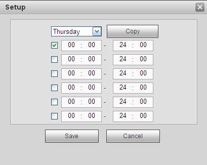
178 Figure 5-54 Figure


179 Figure 5-56 Figure 5-57 Figure
180 Figure 5-59 Please refer to the following sheet for detailed information. Parameter Enable Period Anti-dither Sensitivity Region Record channel Record Delay Alarm out Latch Show message Function You need to check the box to enable motion detection function. Please select a channel from the dropdown list. Motion detection function becomes activated in the specified periods. See Figure There are six periods in one day. Please draw a circle to enable corresponding period. Click OK button, system goes back to motion detection interface, please click save button to exit. System only memorizes one event during the anti-dither period. The value ranges from 5s to 600s. There are six levels. The sixth level has the highest sensitivity. If you select motion detection type, you can click this button to set motion detection zone. The interface is shown as in Figure Here you can set motion detection zone. There are four zones for you to set. Please select a zone first and then left drag the mouse to select a zone. The corresponding color zone displays different detection zone. You can click Fn button to switch between the arm mode and disarm mode. In arm mode, you can click the direction buttons to move the green rectangle to set the motion detection zone. After you completed the setup, please click ENTER button to exit current setup. Do remember click save button to save current setup. If you click ESC button to exit the region setup interface system will not save your zone setup. System auto activates motion detection channel(s) to record once an alarm occurs. Please note you need to set motion detect record period and go to Storage-> Schedule to set current channel as schedule record. System can delay the record for specified time after alarm ended. The value ranges from 10s to 300s. Enable alarm activation function. You need to select alarm output port so that system can activate corresponding alarm device when an alarm occurs. System can delay the alarm output for specified time after an alarm ended. The value ranges from 1s to 300s. System can pop up a message to alarm you in the local host screen if you enabled this function. 170
181 Parameter Buzzer Alarm upload Message Send Tour PTZ Activation Function Check the box here to enable this function. The buzzer beeps when an alarm occurs. System can upload the alarm signal to the centre (Including alarm centre. When 3G network connection is OK, system can send out a message when motion detect occurs. If you enabled this function, System can send out an to alert you when an alarm occurs. You need to click setup button to select tour channel. System begins 1-wiindow or multiple-window tour display among the channel(s) you set to record when an alarm occurs. See Figure Here you can set PTZ movement when alarm occurs. Such as go to preset X. See Figure Snapshot Click setup button to select snapshot channel. See Figure Video Matrix This function is for motion detect only. Check the box here to enable video matrix function. Right now system supports one-channel tour function. System takes first come and first serve principle to deal with the activated tour. System will process the new tour when a new alarm occurs after previous alarm ended. Otherwise it restores the previous output status before the alarm activation Video Loss The video loss interface is shown as in Figure Please note video loss does not support anti-dither, sensitivity, region setup. For rest setups, please refer to chapter motion detect for detailed information. Figure
182 Tampering The tampering interface is shown as in Figure After analysis video, system can generate a tampering alarm when the detected moving signal reached the sensitivity you set here. For detailed setups, please refer to chapter motion detect for detailed information. Figure IVS (Optional) Please make sure you are connecting to the smart network camera, otherwise you can not use IVS function! From main menu->setup->event->ivs, you can go to the IVS interface. It includes four interfaces: Tripwire/intrusion/object/scene Tripwire Please make sure you are connecting to the smart network camera, otherwise you can not use IVS function! From main menu->setup->event->ivs->tripwire, you can see the following interface. See Figure System generates an alarm once there is any object crossing the tripwire in the specified direction. 172


183 Figure 5-62 Check the Tripwire box to enable tripwire function. Select SN (Line1/2/3/4) and direction, and then input customized rule name. No. and Line1/2/3/4: System supports four tripwires. Each SN stands for one tripwire. Direction: There are three options: A->B, B->A, both. System can generate an alarm once there is any object crossing in the specified direction. Now you can draw a rule. Click Draw rule button and then left click mouse to draw a tripwire. The tripwire can be a direct line, curve or polygon. Right click mouse to complete. See Figure Figure

184 Click to draw filter object. See Figure Figure 5-64 Select the blue line and then use mouse to adjust zone size. Note Each rule can set two sizes (min size/max size). Once the object is smaller than the min size or larger than the max size, there is no alarm. Please make sure the max size is larger than the min size. Click Ok to complete the rule setup. For detailed setups, please refer to chapter motion detect for detailed information Intrusion (Cross warning zone) Please make sure you are connecting to the smart network camera, otherwise you can not use IVS function! From main menu->setup->event->ivs->intrusion, the intrusion interface is shown as below. See 错误! 未找到引用源. 174
 the zone. Now you can draw a rule.")
185 Figure 5-65 Check the Intrusion box to enable intrusion function. Select SN (Area1/2/3/4) and direction, and then input customized rule name. No. and Area1/2/3/4: System supports four zones. Each SN stands for one zone. Direction: There are three options: A->B, B->A, both. System can generate an alarm once there is any object enter/exit (Or both) the zone. Now you can draw a rule. Left click mouse to draw a line first and then right click mouse to draw another line until you draw a rectangle, you can right click mouse to exit. Click Ok to complete the rule setup. Click to draw the zone. See Figure


186 Figure 5-66 For detailed setups, please refer to chapter motion detect for detailed information Object Detect Please make sure you are connecting to the smart network camera, otherwise you can not use IVS function! For the same channel,the object detect and the intrusion can not be valid at the same time. From main menu->setup->event->ivs->object, the object interface is shown as below. See Figure Figure

187 Check the Object box to enable object detect function. Select SN (object1/2/3/4) and rule type, and then input customized rule name. No. and Object1/2/3/4: System supports four zones. Each SN stands for one zone. Rule type: Please select from the dropdown list. There are two types: Missing object detect/abandoned object detect. Period: It refers to the object in/out the zone time. Click to draw the rule. See Figure Figure 5-68 Now you can draw a rule. Left click mouse to draw a line, until you draw a rectangle, you can right click mouse. Click Ok to complete the rule setup. For detailed setups, please refer to chapter motion detect for detailed information Change Scene Please make sure you are connecting to the smart network camera, otherwise you can not use IVS function! When the detected scene changes,,the system can generate an alarm. From main menu->setup->event->ivs->change scene, the interface is shown as in Figure


188 Figure 5-69 For detailed setups, please refer to chapter motion detect for detailed information Face Detect (Optional) Please make sure you are connecting to the smart network camera, otherwise you can not use IVS function! When camera detects human face, system can generate an alarm. From main menu->setup->event->face detect, the interface is shown as in Figure Enable face boost: Check the box here, system can enhance the human face display pane. Sensitivity: System supports 6 levels. The sixth level has the highest sensitivity. For detailed setups, please refer to chapter Figure

189 Audio Detect (Optional) Please make sure you are connecting to the smart network camera, otherwise you can not use IVS function! System can generate an alarm once it detect the audio input is abnormal or audio volume changes. From main menu->setup->event->audio detect, you can see an interface shown as in Figure Input abnormal: Check the box here, system can generate an alarm once the audio input is abnormal. Intensity change: Check the box here, system can generate an alarm once the audio volume becomes strong. Sensitivity: It refers to the audio recognition sensitivity. The higher the value is, the higher the sensitivity is. Threshold: It is to set intensity change threshold. The smaller the value is, the higher the sensitivity is. For detailed setups, please refer to chapter motion detect for detailed information. Figure Alarm Before operation, please make sure you have properly connected alarm devices such as buzzer. The input mode includes local alarm and network alarm Local Alarm The local alarm interface is shown as in Figure It refers to alarm from the local device. 179

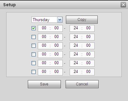
190 Figure 5-72 Figure

191 Figure 5-74 Please refer to the following sheet for detailed information. Parameter Enable Period Anti-dither Sensor type Record channel Record Delay Alarm out Latch Function You need to check the box to enable this function. Please select a channel from the dropdown list. This function becomes activated in the specified periods. There are six periods in one day. Please draw a circle to enable corresponding period. Select date. If you do not select, current setup applies to today only. You can select all week column to apply to the whole week. Click OK button, system goes back to local alarm interface, please click save button to exit. System only memorizes one event during the anti-dither period. The value ranges from 5s to 600s. There are two options: NO/NC. System auto activates motion detection channel(s) to record once an alarm occurs. Please note you need to set alarm record period and go to Storage-> Schedule to set current channel as schedule record. System can delay the record for specified time after alarm ended. The value ranges from 10s to 300s. Enable alarm activation function. You need to select alarm output port so that system can activate corresponding alarm device when an alarm occurs. System can delay the alarm output for specified time after an alarm ended. The value ranges from 1s to 300s. 181
.")
192 Parameter Show message Buzzer Alarm upload Send Tour PTZ Activation Snapshot Function System can pop up a message to alarm you in the local host screen if you enabled this function. Check the box here to enable this function. The buzzer beeps when an alarm occurs. System can upload the alarm signal to the centre (Including alarm centre). If you enabled this function, System can send out an to alert you when an alarm occurs. You need to click setup button to select tour channel. System begins 1-wiindow or multiple-window tour display among the channel(s) you set to record when an alarm occurs. See Figure Here you can set PTZ movement when alarm occurs. Such as go to preset X. See Figure Click setup button to select snapshot channel. See Figure Net Alarm The network alarm interface is shown as in Figure Network alarm refers to the alarm signal from the network. System does not anti-dither and sensor type setup. For setup information, please refer to chapter Figure IPC external alarm The IPC external alarm interface is shown as in Figure Network alarm refers to the alarm signal from the network. System does not anti-dither and sensor type 182


193 setup. For setup information, please refer to chapter Figure IPC Offline Alarm The IPC offline alarm interface is shown as in Figure System can generate an alarm once the network camera is offline. For setup information, please refer to chapter Figure

194 Abnormality It includes six types: No disk, disk error, disks no space, disconnect, IP conflict, MAC conflict. See Figure 5-78 through Figure Figure 5-78 Figure 5-79 Figure 5-80 Figure
195 Figure 5-82 Figure 5-83 Please refer to the following sheet for detailed information. Parameter Event Type Enable Alarm Out Latch Show message Alarm upload Send Function The abnormal events include: No disk, disk error, disk no space, net disconnection, IP conflict and MAC conflict. You can set one or more items here. Less than: You can set the minimum percentage value here (For disk not space only). The device can alarm when capacity is not sufficient. You need to draw a circle to enable this function. Check the box here to enable selected function. Please select corresponding alarm output channel when an alarm occurs. You need to check the box to enable this function. The alarm output can delay for the specified time after an alarm stops. The value ranges from 1s to 300s. System can pop up a message to alarm you in the local host screen if you enabled this function. System can upload the alarm signal to the centre (Including alarm centre. If you enabled this function, System can send out an to alert you when an alarm occurs. 185


196 Parameter Buzzer Function Check the box here to enable this function. The buzzer beeps when an alarm occurs Storage Schedule In this interfaces, you can add or remove the schedule record setup. See Figure There are four record modes: general (auto), motion detect, alarm and MD&alarm. There are six periods in one day. You can view the current time period setup from the color bar. Green color stands for the general record/snapshot. Yellow color stands for the motion detect record/snapshot.. Red color stands for the alarm record/snapshot. Blue color stands for MD&alarm record/snapshot. Figure 5-84 Figure

197 Figure 5-86 Please refer to the following sheet for detailed information. Parameter Channel Function Please select a channel from the dropdown list. Pre-record Please input pre-record time here. The value ranges from 0 to 30. Redundancy Check the box here to enable redundancy function. Please note this function is null if there is only one HDD. Snapshot Holiday Check the box here to enable snapshot function. Check the box here to enable holiday function. Setup Click the Setup button, you can set record period. See Figure There are six periods in one day. If you do not check the date at the bottom of the interface, current setup is for today only. Please click Save button and then exit. Copy Copy function allows you to copy one channel setup to another. After setting in channel, click Copy button, you can go to interface Figure You can see current channel name is grey such as channel 1. Now you can select the channel you want to paste such as channel 187

198 Parameter Function 5/6/7. If you want to save current setup of channel 1 to all channels, you can click the first box ALL. Click the OK button to save current copy setup. Click the OK button in the Encode interface, the copy function succeeded HDD Manager Local Storage The local interface is shown as in Figure Here you can see HDD information. You can also operate the read-only, read-write, redundancy (if there are more than on HDD) and format operation HDD Figure 5-87 The HDD interface is to set HDD group. See Figure Figure FTP The FTP interface is to set FTP information. See Figure Please set the FTP as your remote storage location. System can save record file or snapshot picture to the FTP once the network is offline or malfunction. 188


199 Figure Record Control The interface is shown as in Figure Figure 5-90 Please refer to the following sheet for detailed information. Parameter Channel Status Schedule Function Here you can view channel number. The number displayed here is the max channel amount of your device. There are three statuses: schedule, manual and stop. System enables auto record function as you set in record schedule setup (general, motion detect and alarm). 189
200 Manual Stop Start all/ stop all RAID Manager Important It has the highest priority. Enable corresponding channel to record no matter what period applied in the record setup. Stop current channel record no matter what period applied in the record setup. Check the corresponding All button, you can enable or disable all channels record. Please make sure your purchased product support the RAID function, otherwise you can not see the following interface RAID Config It is for you to manage RAID HDD. It can display RAID name, type, free space, total space, status and etc. Here you can add/delete RAID HDD. Click Add button to select RAID type and then select HDDs, click OK button to add. See Figure Figure Hotspare disks In Figure 5-91, click hotspare button, you can add the hot spare HDD. See Figure The type includes two options: Global: It is global hotspare disk. When any RAID becomes degrading, it can replace and build the RAID. Local: It is local hotspare disk. When the specified RAID becomes degrading, it can replace and build the RAID. Select a hot spare device and then click Delete button. Click Apply button to delete. 190

201 Figure Storage Main Stream The main stream interface is shown as in Figure Here you can set corresponding HDD group to save main stream. Figure Sub Stream The sub stream interface is shown as in Figure Here you can set corresponding HDD group to save sub stream. 191

202 Figure Snapshot The snapshot interface is shown as in Figure Here you can set corresponding HDD group to save snapshot picture. Figure Setting General The general interface includes general, date/time and holiday setup General The general interface is shown as in Figure Figure

203 Please refer to the following sheet for detailed information. Parameter Function Device ID It is to set device name. Device No. Language Video Standard It is device channel number. You can select the language from the dropdown list. Please note the device needs to reboot to get the modification activated. This is to display video standard such as PAL. HDD full Pack duration Date and time Here is for you to select working mode when hard disk is full. There are two options: stop recording or rewrite. If current working HDD is overwritten or the current HDD is full while the next HDD is no empty, then system stops recording, If the current HDD is full and then next HDD is not empty, then system overwrites the previous files. Here is for you to specify record duration. The value ranges from 1 to 120 minutes. Default value is 60 minutes. The date and time interface is shown as in Figure 5-97 Figure 5-97 Please refer to the following sheet for detailed information. Parameter Function Date format Here you can select date format from the dropdown list. 193

204 Time Format Time zone System time Sync PC DST NTP NTP server Port Interval There are two options: 24-H and 12-H. The time zone of the device. It is to set system time. It becomes valid after you set. You can click this button to save the system time as your PC current time. Here you can set day night save time begin time and end time. You can set according to the date format or according to the week format. You can check the box to enable NTP function. You can set the time server address. It is to set the time server port. It is to set the sync periods between the device and the time server Holiday Setup Holiday setup interface is shown as in Figure Here you can click Add holidays box to add a new holiday and then click Save button to save. Figure Account Note: For the character in the following user name or the user group name, system max supports 6-digits. The space in the front or at the end of the string is null. The valid string includes: character, number, and underline. The user amount default setup is 64 and the group amount default setup is 20. The factory default setup includes two levels: user and admin. You can set the corresponding group and then set the rights for the respective user in the specified groups. User management adopts group/user modes. The user name and the group name shall be unique. One user shall be included in only one group. 194

205 User name In this interface you can add/remove user and modify user name. See Figure Figure 5-99 Add user: It is to add a name to group and set the user rights. See Figure There are three default users: admin/ and hidden user default. Hidden user default is for system interior use only and can not be deleted. When there is no login user, hidden user default automatically login. You can set some rights such as monitor for this user so that you can view some channel view without login. Here you can input the user name and password and then select one group for current user. Please note the user rights shall not exceed the group right setup. For convenient setup, please make sure the general user has the lower rights setup than the admin. Figure

206 Modify user It is to modify the user property, belonging group, password and rights. See Figure Modify password It is to modify the user password. You need to input the old password and then input the new password twice to confirm the new setup. Please click the OK button to save. Please note, the password ranges from 1-digit to 6-digit. It shall include the number only. For the user of the account rights, he can modify the password of other users. Figure Group The group management interface can add/remove group, modify group password and etc. The interface is shown as in Figure Figure


207 Add group: It is to add group and set its corresponding rights. See Figure Please input the group name and then check the box to select the corresponding rights. It includes: shutdown/reboot device, live view, record control, PTZ control and etc. Figure Modify group Click the modify group button, you can see an interface is shown as in Figure Here you can modify group information such as remarks and rights. Figure
, 1280 720, 1024 768.")
208 Display Display interface includes GUI, TV adjust, Tour and zero-channel encoding Display Here you can set background color and transparency level. See Figure Figure Please refer to the following sheet for detailed information. Parameter Function Resolution There are four options: , (default), , Please note the system needs to reboot to activate current setup. Color mode Please select from the dropdown list. Transparency Here is for you to adjust transparency. The value ranges from 128 to 255. Time title/channel Check the box here, you can view system time and channel number on the monitor video. title Image Check the box; you can optimize the margin of the preview video. enhance Startup wizard Once you check the box here, system will go to the startup wizard directly when the system restarts the next time. Otherwise, it will go to the login interface. Navigation bar Check the box here, system displays the navigation bar on the interface. 198

209 Original scale Auto logout Display intelligent rule(s) Click the Set button to select a channel, it can restore original scale. Here is for you to set auto logout interval once login user remains inactive for a specified time. Value ranges from 0 to 60 minutes. 0 means there is no standby time. After the auto logout, the user needs to input user name and password to login again. Check the box to enable IVS function, system can display IVS rule on the preview interface Tour The tour interface is shown as in Figure Here you can set tour interval, split mode, motion detect tour and alarm tour mode. Figure Please refer to the following sheet for detailed information. Parameter Enable tour Interval Split Motion tour/alarm tour Function Check the box here to enable tour function. Here is for you to adjust transparency. The value ranges from 5 to 120s. The default setup is 5s. Here you can set window mode and channel group. System can support 1/4/8/9/16/25/36-window according to device channel amount. Here you can set motion detect tour/alarm tour window mode. System supports 1/8-window now Alarm Out 199


210 The alarm output interface is shown as below. See Figure Here you can set alarm output mode: auto/manual/stop. Figure Default The default setup interface is shown as in Figure Here you can select Network/Event/Storage/Setting/Camera. Or you can check the All box to select all items. Figure Import/Export The interface is shown as in Figure This interface is for you to export or import the configuration files. 200


211 Figure Please refer to the following sheet for detailed information. Parameter Browse Import Export Function Click to select import file. It is to import the local setup files to the system. It is to export the corresponding WEB setup to your local PC Auto maintain The auto maintain interface is shown as in Figure Here you can select auto reboot and auto delete old files interval from the dropdown list. If you want to use the auto delete old files function, you need to set the file period. Click Manual reboot button, you can restart device manually. Figure Upgrade The upgrade interface is shown as in Figure Please select the upgrade file and then click the update button to begin update. Please note the file name shall be as *.bin. During the upgrade process, do not unplug the power cable, network cable, or shutdown the device. Important Improper upgrade program may result in device malfunction! Please make sure the operation is operated under the supervision of the professional engineer! 201

212 RS232 The RS232 interface is shown as in Figure Figure Figure Please refer to the following sheet for detailed information PTZ Parameter Protocol Baud Rate Function Select the corresponding dome protocol. Default setup is console. Select the baud rate. Default setup is Data Bit The value ranges from 5 to 8. Default setup is 8. Stop bit There are two options: 1/2. Default setup is 1. Parity There are five options: none/odd/even/space/mark. Default setup is none. The PTZ interface is shown as in Figure (Local) and Figure (Remote). Before setup, please check the following connections are right: PTZ and decoder connection is right. Decoder address setup is right. Decoder A (B) line connects with NVR A (B) line. Click Save button after you complete setup, you can go back to the monitor interface to control speed dome. 202


213 Figure Figure Please refer to the following sheet for detailed information. Parameter Function Channel Select speed dome connected channel. PTZ Type Protocol Address Baud Rate Data Bit There are two options: local/remote. Please select remote type if you are connecting to the network PTZ. Please select local type if you are using RS485 to the PTZ camera. Select the corresponding dome protocol such as PELCOD. Set corresponding dome address. Default value is 1. Please note your setup here shall comply with your dome address; otherwise you can not control the speed dome. Select the dome baud rate. Default setup is The value ranges from 5 to 8. Default setup is 8. Please set according to the speed dome dial switch setup. 203


214 Parameter Function Stop bit Parity The value ranges from 1 to 2. Default setup is 1. Please set according to the speed dome dial switch setup. The options include non/odd/even/space/null. Default setup is none. Please set according to the speed dome dial switch setup. 5.9 Information Version The version interface is shown as in Figure Here you can view record channel, alarm input/output information, software version, release date and etc. Please note the following information is for reference only Log Here you can view system log. See Figure Figure Figure

215 Please refer to the following sheet for log parameter information. Parameter Type Start time Function Log types include: system operation, configuration operation, data operation, event operation, record operation, user management, log clear. Set the start time of the requested log. End time Search Detailed information Clear Backup Set the end time of the requested log. You can select log type from the drop down list and then click search button to view the list. You can click the stop button to terminate current search operation. You can select one item to view the detailed information. You can click this button to delete all displayed log files. Please note system does not support clear by type. You can click this button to backup log files to current PC Online User The online user interface is shown as in Figure Figure Playback Click Playback button, you can see an interface is shown as in Figure
216 Figure Search Record Please set record type, record date, window display mode and channel name. Select Date You can click the date on the right pane to select the date. The green highlighted date is system current date and the blue highlighted date means it has record files. Window Split Select window split mode. Click to display in full screen. Click ESC button to exit. See Figure Figure Select Channel 1~4 means main stream and A1~A4 means sub stream. Select Record Type Check the corresponding box to select record type. See Figure Figure File List Click File list button, you can see the corresponding files in the list. See Figure


217 Figure Playback Select a file you want to play and then click Play button, system can begin playback. You can select to playback in full-screen. Please note for one channel, system can not playback and download at the same time. You can use the playback control bar to implement various operations such as play, pause, stop, slow play, fast play and etc. See Figure Figure


218 Download Select the file(s) you want to download and then click download button, you can see an interface shown as in Figure The Download button becomes Stop button and there is a process bar for your reference. Please go to you default file saved path to view the files. Figure Load more It is for you to search record or picture. You can select record channel, record type and record time to download. Or you can use watermark function to verify file Download By File Select channel, record type, bit stream type and then input start time and end time. Click Search button, the download by file interface is shown as in Figure Figure


219 Check the file(s) you want to download and there are two options for you to save the file(s). Download to local Click Download to local, system pops up the following interface for you to set record format and saved path. See Figure Figure You can click OK to download and view the download process. After the download operation, you can see corresponding dialog box. Download to USB Connect the corresponding p peripheral device, and then click Download to USB button, you can see the following interface. See Figure Figure Select Backup device and backup type first and then click Start backup button. After the download operation, you can see corresponding dialogue box Download by Time Select channel, bit stream type, start time and end time. Click Download to Local button, you can see download by time interface is shown as in Figure


220 Figure Set record format and saved path, you can click OK to download and view the download process. After the download operation, you can see corresponding dialog box Watermark Watermark interface is shown as In Figure Please select a file and then click Verify button to see the file has been tampered with or not Figure Alarm Click alarm function, you can see an interface is shown as Figure Here you can set device alarm type and alarm sound setup (Please make sure you have enabled audio function of corresponding alarm events.). 210

221 Figure Please refer to the following sheet for detailed information. Type Parameter Function Alarm Video loss System alarms when video loss occurs. Type Motion detection System alarms when motion detection alarm occurs. Tampering System alarms when camera is viciously masking. Disk full Disk error External alarm IPC external alarm IPC offline alarm Intelligent detect Audio detect Operation Prompt Alarm Play alarm Sound sound Sound path System alarms when disk is full. System alarms when disk error occurs. Alarm input device sends out alarm. It refers to the on-off signal from the network camera. It can activate the NVR local activation operation. System can generate an alarm when the network camera and the NVR are disconnected. System alarms when IVS alarm occurs. System alarms when audio detect is abnormal. Check the box here, system can automatically pops up an alarm icon on the Alarm button in the main interface when there is an alarm. System sends out alarm sound when an alarm occurs. You can specify as you wish. Here you can specify alarm sound file Log out Click log out button, system goes back to log in interface. See Figure You need to input user name and password to login again. 211
Network Video Recorder Quick Start Guide
 Network Video Recorder Quick Start Guide Model No. K-NL304K K-NL308K Version 1.0.3 Table of Contents 1 Hardware Installation and Connection... 1 1.1 Check Unpacked NVR... 1 1.2 About Front Panel and Rear
Network Video Recorder Quick Start Guide
 Network Video Recorder Quick Start Guide Version 1.5.0 Table of Contents 1 Hardware Installation and Connection... 1 1.1 Check Unpacked NVR... 1 1.2 About Front Panel and Rear Panel... 1 1.3 After Remove
HD Analog Recorder. Quick Start Guide CJ-HDR104. Model No. CJ-HDR108. Version 1.0.2
 HD Analog Recorder Quick Start Guide Model No. CJ-HDR104 CJ-HDR108 Version 1.0.2 Table of Contents 1 Hardware Installation and Connection... 1 1.1 Check Unpacked DVR... 1 1.2 About Front Panel and Rear
Network Video Recorder User s Manual
 Network Video Recorder User s Manual V 1.1.0 Table of Contents 1 Features and Specifications...1 1.1 Overview...1 1.2 Features...1 1.3 Specifications...2 1.3.1 NVR42/42-P/42-8P Series...2 1.3.2 NVR72/72-8P
Tiny Series - User's Manual NVR-ELT4 NVR-ELT-4-POE4 NVR-ELT-16
 Tiny Series - User's Manual NVR-ELT4 NVR-ELT-4-POE4 NVR-ELT-16 PTZ Control 1 yr Motion Activated Recording Warranty View From Anywhere 1080p Resolution Our Units do not support PAL Table of Contents 1
Network Video Recorder Quick Start Guide
 Network Video Recorder Quick Start Guide Version 1.5.1 Table of Contents 1 Hardware Installation and Connection... 1 1.1 Check Unpacked NVR... 1 1.2 About Front Panel and Rear Panel... 1 1.3 After Remove
32 CH NVR s - Manual. 3 yr NVR-EL-32 NVR-ELM-32 NVR-ELM-32-POE8 PTZ. 1080p. Control. Motion Activated Recording. Resolution.
 1080p Resolution 3 yr Warranty Motion Activated Recording 32 CH NVR s - Manual PTZ Control NVR-EL-32 NVR-ELM-32 NVR-ELM-32-POE8 Table of Contents 1 Features and Specifications...1 1.1 Overview...1 1.2
Network Video Recorder User s Manual
 Network Video Recorder User s Manual Table of Contents 1 Features and Specifications 1.1 Overview 1.2 Features 1.3 Specifications 2 Front Panel and Rear Panel 2.1 Front Panel 2.2 Rear Panel 2.3 Alarm Connection
Montavue MNR800 Series NVR User Manual
 Montavue MNR800 Series NVR User Manual Table of Contents 1 Local Basic Operation...1 1.1 Boot up and Shutdown...1 1.1.1 Boot up...1 1.1.2 Shutdown...1 1.2 Change/Reset Password...1 1.2.1 Change Password...1
4.1.1 Boot up Shutdown. 4.2 Change/Reset Password
 Table of Contents 1 Features and Specifications 1.1 Overview 1.2 Features 1.3 Specifications 2 Front Panel and Rear Panel 2.1 Front Panel 2.2 Rear Panel 2.3 Alarm Connection 2.3.1 Alarm Port 2.3.2 Alarm
Network Video Recorder Quick Start Guide
 Network Video Recorder Quick Start Guide Contents Important Safeguards and Warnings... 2 1. Hardware Installation and Connection...2 1.1. Before You Start... 3 1.2. HDD Installation... 3 2. Interface Instruction...4
Network Video Recorder Quick Start Guide
 Network Video Recorder Quick Start Guide Model No. K-NL404K/G K-NL408K/G K-NL416K/G Version 1.0.0 Table of Contents 1 Hardware Installation and Connection... 1 1.1 Preparation Work... 1 1.2 HDD Installation...
IZEUS 4000 NVR RANGE. 8 & 16 Channel Network Video Recorders. User s Manual
 IZEUS 4000 NVR RANGE 8 & 16 Channel Network Video Recorders User s Manual V 1.0.0 09/2014 Copyright Qvis. All documentation rights reserved. i Table of Contents 1 Features and Specifications... 1 1.1 Overview...
Network Video Server Quick Start Guide
 Network Video Server Quick Start Guide Version 1.0.0 Table of Contents 1 Hardware Installation and Connection... 1 1.1 Check Unpacked Device... 1 1.2 About Front Panel and Rear Panel... 1 1.3 After Remove
Eyemax 4K H265 32CH 16PoE 8HDD upto 8MP Network Video Recorder
 H.265/H.264 codec decoding Max 200Mbps Incoming Bandwidth Up to 8MP Resolution for Preview and Playback HDMI/VGA simultaneous video output Support IPC UPnP 16PoE ports Support ANR technology to enhance
Eyemax H264 4CH 4PoE 1HDD upto 6MP NVR
 H.264+/H.264 codec decoding Max 80Mbps incoming bandwidth Up to 6Mp resolution preview&playback HDMI/VGA simultaneous video output 3D intelligent positioning with Dahua PTZ camera System Overview Eyemax
3 yr. Elite Mini POE Series - User's Manual NVR-ELM-8-POE-8-DH PTZ. 1080p. Warranty. Resolution. Control. Motion Activated Recording
 Elite Mini POE Series - User's Manual NVR-ELM-8-POE-8-DH PTZ Control Motion Activated Recording 3 yr Warranty View From Anywhere 1080p Resolution Our Units Do Not Support PAL Table of Contents 1 Features
NVR-ELE16C-4KS. 2 yr PTZ. Resolution. Control. Warranty. View From Anywhere. Motion Activated Recording
 NVR-ELE16C-4KS PTZ Control Motion Activated Recording 2 yr Warranty View From Anywhere 4K Resolution Table of Contents 1 Features and Specifications 1.1 Overview 1.2 Features 1.3 Specifications 2 Front
3 yr PTZ. 4k NVR 8 Channel - User s Manual ELI-SIP2-NVR8 ELI-SIP2-NVR8POE UP TO. Control. Warranty. Resolution 8 CAMERAS.
 4k NVR 8 Channel - User s Manual ELI-SIP2-NVR8 ELI-SIP2-NVR8POE IP Network 4K Resolution UP TO 8 CAMERAS 3 yr Warranty Motion Activated Recording PTZ Control 800.683.6835 8. elinetechnology.com Table of
Network Video Recorder Quick Start Guide
 Network Video Recorder Quick Start Guide Version 1.0.0 Table of Contents 1 Preparation Work... 1 2 HDD Installation... 2 2.1 SMART BOX... 2 2.2 SMART 1U... 2 2.3 MINI 1U, COMPACT 1U, 1U... 3 3 Rear Panel...
DH-KIT/NVR4104H-P/4-HFW1220S-0360B
 4 CH HD Network Surveillance Security System Features SUPPORT P2P,ALLOWING EASIER HOME APPLICATIONS ALL CHANNEL SYNCHRONOUS REALTIME PLAYBACK ALL CAMERAS WITH 1080P REALTIME PREVIEW H.264 DUAL-STREAM VIDEO
WiFi NVR-Recorder PRO TX-64 User Manual
 WiFi NVR-Recorder PRO TX-64 User Manual V 1.0.0 Table of Contents 1 Features and Specifications...1 1.1 Overview...1 1.2 Features...1 1.3 Specifications...3 2 Front Panel and Rear Panel...5 2.1 Front Panel...5
Network Video Recorder User s Manual
 Network Video Recorder User s Manual V 2.0.0 Table of Contents 1 Features and Specifications... 1 1.1 Overview... 1 1.2 Features... 1 1.3 Specifications... 2 1.3.1 NVR7508K... 2 1.3.2 NVR7516K/7532K...
HD DVR Series. Quick Start Guide. Version 1.1.0
 HD DVR Series Quick Start Guide Version 1.1.0 Thank you for purchasing our DVR! This quick start guide will help you become familiar with our DVR in a very short time. Before installation and operation,
HDCVI Technical Highlights HD Video format: Analog Modulation: Transmission over coaxial cable: Auto Compensation & Long range transmission:
 HDCVI (High Definition Composite Video Interface) is an over-coaxial-cable analog HD video transmission standard which developed in-house. The technology renders two HD video formats X1920H (1920x1080)
NVR Series Quick Start Guide
 NVR Series Quick Start Guide V5.2.0 Table of Contents 1 INSTALLATION AND CONNECTIONS... 1 1.1 Check Unpacked NVR... 1 1.2 Front Panel... 1 1.2.1 Super 3U NVR / Super 4K 3U NVR/ Super 4K S2 3U NVR Series...
Dahua HDCVI Series DVR User s Manual Version 1.2.0
 Dahua HDCVI Series DVR User s Manual Version 1.2.0 4 OVERVIEW OF NAVIGATION AND CONTROLS... 93 4.1 Boot up and Shutdown...93 4.1.1 Boot up...93 4.1.2 Shutdown...93 4.1.3 Auto Resume after Power Failure...93
Network Video Recorder Quick Start Guide
 Network Video Recorder Quick Start Guide Version 1.0.0 Table of Contents 1 Hardware Installation and Connection... 1 1.1 Preparation Work... 1 1.2 HDD Installation... 1 2 Front Panel/Rear Panel... 3 3
Network Video Recorder User s Manual
 Network Video Recorder User s Manual Model No. K-NL304K K-NL308K K-NL316K Version 1.0.4 Table of Contents 1 Features and Specifications... 1 1.1 Overview... 1 1.2 Features... 1 1.3 Specifications... 3
Network Video Recorder Quick Start Guide
 Network Video Recorder Quick Start Guide Version 1.1.0 Table of Contents 1 Hardware Installation and Connection... 1 1.1 Check Unpacked NVR... 1 1.2 About Front Panel and Rear Panel... 1 1.3 After Remove
DH-KIT/NVR2104-P-S2/4-HFW1220S-S2
 4 CH FHD 1080P Network Surveillance Security System Features Support P2P, allowing easier home applications All channel synchronous real-time playback All cameras with 1080P real-time preview H.264 Dual-stream
Eyemax 1080P 4CH Penta-brid 1U Digital Video Recorder
 Embedded processor H.264+/H.264 video compression Support HDCVI/AHD/TVI/CVBS/IP video inputs Max 6/12/24 channels IP camera inputs each channel up 5MP Max 24/48/96Mbps Incoming Bandwidth Smart Search and
Eyemax 1080P 32 CH Penta-brid Digital Video Recorder with 1.5U
 Embedded processor H.264+/H.264 dual-stream video compression Support HDCVI/AHD/TVI/CVBS/IP video inputs Max 12/24/32 channels IP camera inputs each channel up Max 48/96/128Mbps Incoming Bandwidth > Smart
MVR-SQ-40 & MVR-SQ-80 Series DVR Quick Start Guide
 MVR-SQ-40 & MVR-SQ-80 Series DVR Quick Start Guide Thank you for purchasing a MaceView SQ Series DVR. Please read the instructions completely before installation. Please consult a legal expert on the proper
Network Video Recorder User s Manual
 Network Video Recorder User s Manual V 1.4.1 Table of Contents 1 Features and Specifications...1 1.1 Overview...1 1.2 Features...1 1.3 Specifications...2 1.3.1 NVR4i-P/NVR8i-P Series...2 1.3.2 NVR704NS-P/NVR716NS-P/NVR732NS-P
Network Video Decoder Quick Start Guide
 Network Video Decoder Quick Start Guide V3.4.0 Table of Contents 1 FRONT PANEL/REAR PANEL/INSTALLATION... 1 1.1 Check Unpacked Device... 1 1.2 Front panel... 1 1.2.1 1/4-channel 4K High Definition &1/4-channel
DH-KIT/NVR4104HS-W-S2/2-HFW1320S-W-0360B/2- HDBW1320E-W-0360B
 4 CH 1080P WiFi Network Surveillance Security System Features Easy installation, plug&play Support P2P, allowing easier home applications Support WPS, make easier connection H.264 dual-stream video compression
Amcrest HDCVI DVR Quick Start Guide
 Amcrest HDCVI DVR Quick Start Guide Version 2.0.0 Welcome Thank you for purchasing our Amcrest HDCVI DVR! This quick start guide will help you become familiar with our DVR in a very short time. Before
EYEMAX 16 Ch Penta-brid DVR System, H.265+, 4K IP/CVI Input, 5MP TVI/AHD, 1U, 2 HDD Slots
 Embedded processor H.265+/H.265 dual-stream video compression Support HDCVI/AHD/TVI/CVBS/IP video inputs Max 8 channels IP camera inputs, each channel up to 8MP; Max 48Mbps Incoming Bandwidth Smart Search
ELI-SIP2- NVR32 32 CHANNEL 2U NETWORK VIDEO RECORDER CNVRJ
 ELI-SIP2- NVR32 32 CHANNEL 2U NETWORK VIDEO RECORDER CNVRJ 800.683.6835 eli ne Technology.com OUR UNITS DO NOT SUPPORT PAL Table of Contents 1 Features and Specifications 1.1 Overview 1.2 Features 1.3
Mobile NVR Installation Instruction Guide
 Mobile NVR Installation Instruction Guide V1.0.0 Table of Contents 1 BASIC REQUIREMENTS... 1 1.1 Components (One Vehicle)... 1 1.2 Engineering Materials... 1 2 SYSTEM STRUCTURE... 2 3 INSTALLATION REQUIREMENTS...
Network Video Recorder User s Manual
 Network Video Recorder User s Manual V 5.0.0 Table of Contents 1 Features and Specifications...1 1.1 Overview...1 1.2 Features...1 1.3 Specifications...2 1.3.1 NVR 6000/6064 Series...2 1.3.2 NVR 724-256
EYEMAX 4 Ch Penta-brid DVR System, H.265+, 4K IP/CVI Input, 5MP TVI/AHD, 1U, 1 HDD Slot
 H.265+/H.265 dual-stream video compression Supports HDCVI/AHD/TVI/CVBS/IP video inputs Max 2 channels IP camera inputs, each channel up to 8MP Max 24Mbps Incoming Bandwidth Smart Search and Intelligent
Network Video Recorder User Manual
 Network Video Recorder User Manual Version 1.0.4 Revised November 21 st, 2018 Content Welcome... 6 Important Safeguards and Warnings... 6 1 Overview and Features... 7 1.1. Overview... 7 1.2. Features...
Motion Activated Recording
 1080p Resolution 3 yr Warranty Motion Activated Recording 16 CH NVR s - Manual PTZ Control NVR-ELC-16 NVR-ELC-16-POE16 NVR-ELM-16 Our NVR will record up to 16 individual IP based cameras up to 2 Megapixel
EYEMAX 4+2 CH Penta-brid HD-Coax DVR System, H.265+, 4M-N TVI/CVI/AHD, 6MP IP, CVBS, 1U, 1 HDD Slot
 Smart H.265+ CVI / AHD / TVI / CVBS Auto-detect 4M-N Support IP Camera Support up to 6MP Coaxial Audio Long Distance Transmission Smart Fan Design Intelligent Video System (IVS) Face Detection Smart Search
4-Channel DVR Kit Specification
 4-Channel DVR Kit Specification Package Contents Quantity DVR 1 Camera 4 1 to 4 power-split cable 1 Video Cable 4 USB Mouse 1 12V 2A Power Adapter 2 12V 4A Power Adapter N/A Remote Controller 1 Quick Installation
NXL NVR User Manual V1.0
 NXL NVR User Manual V1.0 Table of Contents 1 Features and Specifications... 8 1.1 Overview... 8 1.2 Features... 8 1.3 Specifications... 9 1.3.1 NXL NVR... 9 2 Front Panel and Rear Panel... 11 2.1 Front
Software Manual EVI Standalone DVR User s Manual
 Software Manual EVI Standalone DVR User s Manual Default: Username: admin Password: 1234 140217 i Table of Contents 1 OVERVIEW OF NAVIGATION AND CONTROLS... 1 1.1 Boot up and Shutdown... 1 1.1.1 Boot up...
NXP NVR User Manual V1.0
 NXP NVR User Manual V1.0 Table of Contents 1 Features and Specifications... 9 1.1 Overview... 9 1.2 Features... 9 1.3 Specifications... 10 1.3.1 NXP NVR... 10 2 Front Panel and Rear Panel... 12 2.1 Front
(ENTERPRISE v2) Features
 Features") (ENTERPRISE v2) IBS Integrated Video Management System (IVMS) comprise of 3 major system components: Digital Server Surveillance System (DSSS), Monitoring Surveillance System (MSS) and Network Video Recorder
(ENTERPRISE v2) IBS Integrated Video Management System (IVMS) comprise of 3 major system components: Digital Server Surveillance System (DSSS), Monitoring Surveillance System (MSS) and Network Video Recorder
Motion Activated Recording
 1080p Resolution 3 yr Warranty Motion Activated Recording 16 CH NVR s - Manual PTZ Control ECL-NVR16 ECL-NVR16M Our NVR will record up to 16 individual IP based cameras up to 2 Megapixel (1080P) resolutions
A0. HD 16 Channel Digital Video Recorder Quick Start Guide
 8200-1368-02 A0 HD 16 Channel Digital Video Recorder Quick Start Guide Notice Please read this manual thoroughly and save it for future use before attempting to connect or operate this unit. The information
Standalone DVR Quick Start Guide
 Standalone DVR Quick Start Guide Version 1.0.0 Table of Contents 1 Hardware Installation and Connection... 1 1.1 Check Unpacked DVR... 1 1.2 About Front Panel and Rear Panel... 1 1.3 After Remove the Chassis...
NVR User Manual. NVR User Manual For further help, please visit
 NVR User Manual NVR User Manual For further help, please visit www.zmodo.com Introduction This product series is a 4 channel embedded NVR with pentaplex functionality: the product will perform video audio
HD Analog Recorder User s Manual
 HD Analog Recorder User s Manual Model No. CJ-HDR104 CJ-HDR108 Version 1.0.3 Table of Contents 1 FEATURES AND SPECIFICATIONS... 1 1.1 Overview... 1 1.2 Features... 1 1.3 Specifications... 2 1.3.1 CJ-HDR104
VMS-A1 Client Software. User Manual
 VMS-A1 Client Software User Manual Contents Contents... 2 Chapter1. Overview... 4 1.1 Description... 4 1.2 Features & Functions... 4 Chapter2. Update Info... 6 Chapter3. Starting VMS-A1... 7 3.1 Installing
Mobile Portable Terminal Quick Start Guide
 Mobile Portable Terminal Quick Start Guide Version 1.0.0 Table of Contents 1 Product Introduction... 1 1.1 Overview... 1 1.2 Packing List... 1 2 Structure and Installation... 2 2.1 Device Structure...
HD Analog Recorder User s Manual
 HD Analog Recorder User s Manual Model No. CJ-HDR216 CJ-HDR416 Version 1.0.3 Table of Contents 1 FEATURES AND SPECIFICATIONS... 1 1.1 Overview... 1 1.2 Features... 1 1.3 Specifications... 2 2 OVERVIEW
Network Video Decoder User s Manual
 Network Video Decoder User s Manual V3.4.0 Table of Contents 1 OVERVIEW... 8 1.1 General Introduction... 8 1.2 Features... 13 2 FRONT PANEL/REAR PANEL/INSTALLATION... 22 2.1 Check Unpacked Device... 22
Standalone DVR Quick Start Guide
 Standalone DVR Quick Start Guide Version 1.1.0 Table of Contents 1 Hardware Installation and Connection... 1 1.1 Check Unpacked DVR... 1 1.2 About Front Panel and Rear Panel... 1 1.3 After Remove the Chassis...
Pro71600N3 NVR User Manual
 Pro71600N3 NVR User Manual User Information Admin User Name: Admin Password: IP Address: System Name: Table Of Contents 1. Menu Operation...4 1.1 Main Menu...4 2. Start & Shutdown System...5 2.1 Start
HDCVI Standalone DVR User s Manual
 HDCVI Standalone DVR User s Manual V1.1.0 Table of Contents 1 FEATURES AND SPECIFICATIONS...1 1.1 Overview...1 1.2 Features...1 1.3 Specifications...2 1.3.1 General 720P (V2) 1U Series...2 1.3.2 Advanced
Pro7804N1 NVR User Manual
 Pro7804N1 NVR User Manual Pro7804N1 User Manual BW R6.indd 1 User Information Admin User Name: Admin Password: IP Address: System Name: Table Of Contents 1. Menu Operation...4 1.1 Main Menu...4 2. Start
Keyboard User s Manual
 Keyboard User s Manual Version 1.0.0 1 Table of Contents 1 Features and Specifications... 7 1.1 Features... 7 1.2 Front Panel... 7 1.3 Rear Panel... 9 1.3.1 NKB1000 Series... 9 1.3.2 KB1000 Series... 9
Combo Digital Video Recorder Quick Start Guide
 Combo Digital Video Recorder Quick Start Guide 1 Table of Contents 1 Hardware Installation and Connection...6 1.1 Check Unpacked Combo DVR...6 1.2 About Front Panel and Rear Panel...6 1.3 Device Installation...6
DVR Serie PRO H960 - Analog Ip. Model. Features
 DVR Serie PRO H960 - Model ST620H-AI: ch DVR/NVR, support @960H/2@100P, 2 HD, RS5, Alarm, Audio, HDMI. ST620H-AI: ch DVR/NVR, support @960H/@720P, 2 HD, RS5, Alarm, Audio, HDMI. ST62H-AI: ch DVR/NVR, support
DDNS UPNP
 PL-ADR0608/16-H2 PL-ADR0604-H2 Content 1 Product Introduction... 3 2 Installation... 3 2.1 Open-package Inspection... 3 2.2 Hard Disk Installation... 3 3. Local operation guide... 3 3.1 Boot operation...
K6 Series Home Use IP Camera User s Manual
 K6 Series Home Use IP Camera User s Manual Version 1.4 Table of Contents 1 General Introduction...6 1.1 Overview...6 1.2 Features...6 1.3 Specifications...7 1.3.1 Performance...7 1.3.2 Function Specifications...7
IP Apartment System Quick Start Guide
 IP Apartment System Quick Start Guide Version 1.0.0 Welcome Thank you for purchasing our device! This quick start guide will help you become familiar with our device in a very short time. Before installation
HLong Asia Industrial
 SDI DVR Stand alone digital video recorder HLong Asia Industrial Thank you for using the company's products! This manual describes only the host functions basic operation. Product design and specification
DS-9000 Series Hybrid Net DVR
 DS-9000 Series Hybrid Net DVR Overview DS-9000 series net DVR is the Hybrid DVR of a new generation designed by HIKVISION. The product combines various patents, along with advanced IT technologies such
IPC Online Operation Manual
 IPC Online Operation Manual 1 Overview An IP camera (hereinafter referred to as IPC) is a new product integrating network video technologies into a traditional camera. The IPC can realize simpler monitoring
VONNIC Standalone DVR Quick Start Guide
 VONNIC Standalone DVR Quick Start Guide Version 6.0.3 Table of Contents 1 Hardware Installation and Connection... 1 1.1 Check Unpacked DVR... 1 1.2 About Front Panel and Rear Panel... 1 1.3 After Remove
Block Camera User s Manual
 Block Camera User s Manual Version 1.0.1 Welcome Thank you for purchasing our block camera! This user s manual is designed to be a reference tool for your system. Please read the following safeguard and
High-Speed Positioning System User s Manual. Version 1.0.1
 High-Speed Positioning System User s Manual Version 1.0.1 Welcome Thank you for purchasing our high-speed positioning system! This user s manual is designed to be a reference tool for your system. Please
N6 CIF Series Standalone DVR Quick Start Guide
 N6 CIF Series Standalone DVR Quick Start Guide Version 1.0.1 Table of Contents 1 Hardware Installation and Connection... 1 1.1 Check Unpacked DVR... 1 1.2 About Front Panel and Rear Panel... 1 1.3 After
HDCVI Standalone DVR User s Manual
 HDCVI Standalone DVR User s Manual V1.5.1 Table of Contents 1 FEATURES AND SPECIFICATIONS... 1 1.1 Overview... 1 1.2 Features... 1 1.3 Specifications... 2 1.3.1 Premium General 4-HDD 720P 1.5U Series...
SDI Digital Video Recorder. Quick Operation Guide
 SDI Digital Video Recorder Quick Operation Guide Thank you for purchasing our product. If there is any question or request, please do not hesitate to contact dealer. This manual is applicable to HDDVRXXXX-SDI
Figure 4-9. Click Finish button, system pops up a dialogue box. Click the OK button, the startup wizard is complete. See Figure 4-10.
 For detailed information, please refer to chapter 4.11.4.1.1. Figure 4-9 Finish button, system pops up a dialogue box. the OK button, the startup wizard is complete. See Figure 4-10. Figure 4-10 4.4 Preview
N6 Series Standalone DVR User s Manual
 N6 Series Standalone DVR User s Manual Version 5.0.0 Table of Contents 1 FEATURES AND SPECIFICATIONS... 1 1.1 Overview...1 1.2 Features...1 1.3 Specifications...2 1.3.1 1U Series...2 1.3.2 1.5U Series...6
Tribrid DVR User s Manual
 Tribrid DVR User s Manual V1.3.0 Table of Contents 1 FEATURES AND SPECIFICATIONS... 1 1.1 Overview... 1 1.2 Features... 1 1.3 Specifications... 2 1.3.1 Premium General 4-HDD 720P 1.5U Series... 2 1.3.2
"ENTERPRISE SERIES" HDMI D1 Digital Video Recorder with DVD/RW. Internet and Cell Phone Live Remote Viewing
 "ENTERPRISE SERIES" HDMI D1 Digital Video Recorder with DVD/RW Internet and Cell Phone Live Remote Viewing Welcome...1 Important Safeguards and Warnings...1 Electrical Safety...1 Shipping Instructions...1
DS-9600NI-ST Series NVR. Technical Specification
 DS-9600NI-ST Series NVR Technical Specification Notices The information in this documentation is subject to change without notice and does not represent any commitment on behalf of HIKVISION. HIKVISION
Analog High Definition DVR. Stand alone digital video recorder. User Manual H.264 AHD DVR
 Analog High Definition DVR Stand alone digital video recorder User Manual H.264 AHD DVR WARNING To reduce the risk of fire or electric shock, do not expose this appliance to rain or moisture. All the safety
Standalone XVR User s Manual
 Standalone XVR User s Manual V1.0.0 Table of Contents 1 FEATURES AND SPECIFICATIONS... 1 1.1 Overview... 1 1.2 Features... 1 2.4 Remote Control... 2 2.5 Mouse Control... 4 2.6 Virtual Keyboard & Front
Dahua NVS User s Manual
 Dahua NVS User s Manual Dahua NVS User s Manual V1.0.1 Table of Contents 1 FEATURES AND SPECIFICATIONS... 1 1.1 Overview... 1 1.2 Features... 1 1.3 Specifications... 2 1.3.1 NVS0X04HDC-A Series... 2 1.3.2
NVR-ELE4ME-4PS2. 4 Channel NVR with PoE
 NVR-ELE4ME-4PS2 4 Channel NVR with PoE Table of Contents 1 Features and Specifications... 1.1 Overview... 1.2 Features... 1.3 Specifications... 1.3.2 Compact 1U(S2)Series. 2 Front Panel and Rear Panel...
Standalone DVR Quick Start Guide
 Standalone DVR Quick Start Guide Version 2.0.1 Table of Contents 1 Hardware Installation and Connection... 1 1.1 Check Unpacked DVR... 1 1.2 About Front Panel and Rear Panel... 1 1.3 After Remove the Chassis...
Federal Mini DVR User's Manual. Our units do not support PAL
 Federal Mini DVR User's Manual Our units do not support PAL Table of Contents 1 FEATURES AND SPECIFICATIONS... 1 1.1 Overview...1 1.2 Features...1 1.3 Specifications...2 1.3.4 Federal Mini Series...12
Dahua HDCVI Standalone DVR User s Manual
 Dahua HDCVI Standalone DVR User s Manual Dahua HDCVI Standalone DVR User s Manual V1.1.0 Table of Contents 1 FEATURES AND SPECIFICATIONS...1 1.1 Overview...1 1.2 Features...1 1.3 Specifications...2 1.3.1
DS-7200HWI-SH Series DVR. Technical Specification
 DS-7200HWI-SH Series DVR Technical Specification Notices The information in this documentation is subject to change without notice and does not represent any commitment on behalf of HIKVISION. HIKVISION
R4, R8, R16 Digital Video Recorders Quick Setup Guide
 R4, R8, R16 Digital Video Recorders Quick Setup Guide This guide provides instructions to initially setup the R16 (16 channel) digital video recorders (DVR). The DVR supports these advanced features: 2
HD Mini IR Waterproof Fixed Network Camera. Quick Start Guide. Version 1.0.2
 HD Mini IR Waterproof Fixed Network Camera Quick Start Guide Version 1.0.2 Welcome Thank you for purchasing our network camera! This quick start guide is designed to be a reference tool for your system.
Pro7400H1 Hybrid DVR User Manual
 Pro7400H1 Hybrid DVR User Manual User Information Admin User Name: Admin Password: IP Address: System Name: Table Of Contents 1. Menu Operation... 4 1.1 Main Menu... 4 2. Start Up/Shutdown System... 5
SiBell Network Video Recorder (NVR) User Manual
 User Manual") SiBell Network Video Recorder (NVR) User Manual NVR-NV9000 Version:001 Please read this manual carefully for correct use of the product and preserve it for reference purposes. (specifications subject to
SiBell Network Video Recorder (NVR) User Manual NVR-NV9000 Version:001 Please read this manual carefully for correct use of the product and preserve it for reference purposes. (specifications subject to
Tribrid Series - User's Manual TRIDVR-EL16-DH. 3 yr PTZ. 1080p. Control. View From Anywhere. Motion Activated Recording. Resolution.
 Tribrid Series - User's Manual TRIDVR-EL16-DH PTZ Control Motion Activated Recording 3 yr Warranty View From Anywhere 1080p Resolution Our units do not support PAL Table of Contents 1 FEATURES AND SPECIFICATIONS...
DS-7700NI-ST Series NVR. Technical Specification
 DS-7700NI-ST Series NVR Technical Specification Notices The information in this documentation is subject to change without notice and does not represent any commitment on behalf of HIKVISION. HIKVISION
DS-7600NI-SE/P Series NVR. Technical Specification
 DS-7600NI-SE/P Series NVR Notices The information in this documentation is subject to change without notice and does not represent any commitment on behalf of HIKVISION. HIKVISION disclaims any liability
HD IR Waterproof Fixed Network Camera. Quick Start Guide. Version 1.0.0
 HD IR Waterproof Fixed Network Camera Quick Start Guide Version 1.0.0 Welcome Thank you for purchasing our network camera! This quick start guide is designed to be a reference tool for your system. Please