USER MANUAL.
|
|
|
- Simon Powers
- 6 years ago
- Views:
Transcription


1 150 USER MANUAL
2 1. Introduction 1. INTRODUCTION HOW TO USE THIS MANUAL PRECAUTIONS Safety Protection OVERVIEW APPEARANCE SPECIFICATIONS Printer Physical Characteristics Specifications Environmental specifications OPERATION PREPARATION Installation the printer Installing the software Installing drivers USING THE BASIC FUNCTIONS Start the program Loading a 3D model View Options Model transformations Placing models onto the build platform GETTING READY TO PRINT Initializing the Printer Calibrating the Nozzle Height Other Maintenance Options Preparing the Platform... 错误! 未定义书签 4. PRINTING MODEL REMOVAL MAINTENANCE CHANGING THE MATERIAL VERTICAL CALIBRATION CLEANING THE NOZZLE REMOVING /CHANGING THE NOZZLE LUBRICATION OF BEARINGS... 错误! 未定义书签 6.6 SPARE PARTS TIPS & TRICKS TROUBLESHOOTING SOLUTION FOR "WINUSB.DLL NOT FOUND" PROBLEM
3 1. Introduction 1. Introduction 1.1 How to use this manual This User Manual is divided into four sections which cover Introduction, Overview, Operation, and Troubleshooting, respectively. Please read this manual carefully before install and operate this machine. Keep this manual handy and refer to it when it is needed. 1.2 Precautions Please read the following precautions carefully before operating the printer Safety Q150 can only be used with the power adapters supplied by Quant3D. Other adapters could damage the printer with risk of fire. During the period that printer is printing, and just after printer is done printing, print platform, nozzle and printed model are still hot. In order to avoid being burnt or cause deformation of model, do not touch model, nozzle, or print platform by hand without any protection. Protective glasses should always be worn when removing support structure, especially when printing material is PLA. The melting point of the brown sections of protection gloves supplied with the printer is about 200 C. Please do not hold the nozzle with the gloves when nozzle is heated. Slight smell will be generated from printing material when printer is extruding filament. A well ventilated room is highly recommended. The following icons are used in this manual: CAUTION: Indicating potential hazardous situation in which, if not avoided, may cause minor or moderate injury. WARNING: Indicating potential hazardous situation in which, if not avoided, may cause serious injury. 3
4 1. Introduction Gloves: When performing a certain maintenance work, machine may be hot and protective gloves are required to avoid being burnt. Safety Glasses: Wear safety glasses to avoid injury to the eyes Protection Q150 printer must not be exposed to water or rain, otherwise may cause damage. Do not shut down Q150 Printer or pull the USB cable during the process of loading a digital model to Printer, otherwise the model data may not be transmitted successfully. When using the Extrude function, keep at least 50mm gap between the nozzle and the print platform. If the gap is too small, nozzle may not extrude filament easily, which could cause nozzle clog. Q150 printer is designed to function properly at temperature between 15 C and 30 C and humidity between 20% and 50%; Operating outside these limits may cause low print quality. 4

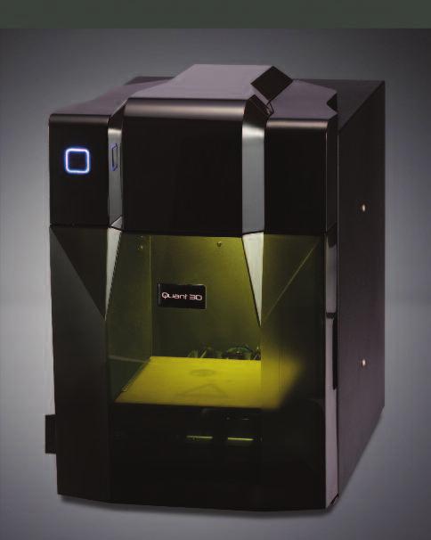
5 2. Overview 2. Overview Q150 is designed with ultimate portability and simplicity in mind. The machine and software allow you to print great models with only a few keystrokes, even you are a first time user of Q150 printer. Q150 uses a nozzle to deposit molten plastic, and the printed parts are strong and durable with high accuracy. 2.1 Appearance Init. Button Figure 2-1 Front view 5

6 2. Overview Extrusion head Nozzle Platform Figure 2-2 Inside View Roller Shaft USB Interface Power On/off Power Interface Figure 2-3 Back view 6


7 2. Overview 1 USB cable 2 Power adapter (20 V) 3 Filament tube 4 Screws 5 Cell board 6 Extrusion head 7 ABS spool Figure 2-4 Accessories 1 Pen Knives 2Tweezers 3 Hex wrench 4 Shovel 5 Pliers 6 Gloves 7 Nozzle wrench Figure 2-5 Tool kit 7
8 2. Overview Y axis Z axis X axis Figure 2-6 Axis 2.2 Specifications Physical Specifications Printing Material ABS or PLA Material Color White/Black/Red/Yellow/Blue/Green Layer Thickness mm Print Speed cm 3 /h Print Size mm Printer Weight 5 KG (11 lb) Printer Size mm Other Specifications Power Requirements Model Support VAC, 50-60Hz, 200W Auto-generated support 8
9 2. Overview Input Format OS compatibility STL Windows XP/Vista/7/8; Mac Environmental specifications Ambient Temperature Relative humidity 15 C ~30 C 20%~50% 9


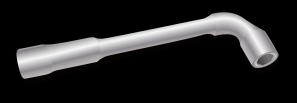
10 3. Operation 3. Operation 3.1 Preparation Installation Figure 3-1 Print head installation Extrusion Head The extrusion head of a Q150 is fastened by three magnetic buckles. When assembling extrusion head, make sure the extrusion head is securely contacted with all the three buckles at right position. 10


11 3. Operation Figure 3-2 Print Platform Platform Insert the cell board into the platform slot. Moderate force is recommended when inserting the cellboard. Figure 3-3 Roller Shaft Roller shaft Insert the roller shaft into the hole at the back of printer, and press it downward. The roller shaft should fit in the hole nicely. 11
 Put a spool of material on the roller shaft, find the end of the material, insert it into filament tube, pass the material through the tube, and pass the tube through the top")
, connect the computer with printer through USB cable, initialize the printer from the software, and, in the software menu, click 3D Print -> Maintenance to bring up the")

12 3. Operation Material Extrusion (top view) Figure 3-4 Material Wiring (1) Connect power adapter to power interface. (2) Put a spool of material on the roller shaft, find the end of the material, insert it into filament tube, pass the material through the tube, and pass the tube through the top of the machine cover. (3) Start Software installed on a computer (If you have not already installed the software, please refer to the software installation procedure in section 3.1.2), connect the computer with printer through USB cable, initialize the printer from the software, and, in the software menu, click 3D Print -> Maintenance to bring up the Maintenance dialogue, where you will find Extrude button. Click the Extrude button, which triggers extrusion process to start. (4) Print nozzle starts warming up. When the temperature of the nozzle reaches 260 C, printer will give off a beep. You can push the filament into the hole at the top of the extrusion head. Hold the filament there with pressure until the extrusion motor inside the print head grabs the filament 12

13 3. Operation and starts pulling it through the extrusion head. From the nozzle side, a string of melted filament will be extruded. (Windows version) (Mac version) Figure 3-5 Maintenance Dialog Software Installation The software is available for download on our site quant3d.com. It is free for everyone who owns a Quant3D printer. After downloading the software installer from the website, start the "setup.exe", and install the program to a specified directory (Default location is c:/program files/up). The installation process will 13


14 3. Operation install the software, the printer drivers, and the sample files. Figure 3-6 Software Directory Driver Installation Connect the printer to a computer with a USB cable. The computer should pop up the Found New Hardware Wizard window. Choose No, not this time option, and then click Next. Choose Install from a list or specific location (Advanced), and click Next. Figure 3-7 Snap shots of Software installation 14


15 3. Operation Click Browse, and choose C:\Program Files\UP\Driver, then Next. Figure 3-8 Snap shots of Software installation The following dialogue box pops up. Choose Continue Anyway, and the drivers will install automatically. Figure 3-9 Snap shots of Software installation If you have any problems installing the driver, or get a "Winusb.dll not found" error, please refer to the driver section in the troubleshooting section of this manual. 15
, and the UP3 format (UP s proprietary compressed STL format).")
16 3. Operation 3.2 Using the basic functions Start the program Click on the up as the following: icon in a computer desktop. The program should open Figure 3-10 Program Startup Screen Loading a 3D model Click File / Open or on the toolbar and select the model you want to load. UP! software supports STL files (the standard input format for 3D printing), and the UP3 format (UP s proprietary compressed STL format). Move the mouse onto the model, and click the left mouse button. Model information will be presented in a floating window, as shown below: 16


17 3. Operation (Windows version) (Mac version) Figure 3-11 Program Model Screen TIP: You can open several models and print them all at the same time. Just repeat the open model procedure for each model you want to add. See the Placing models on the build platform section for more information. Unloading a model: click the left mouse button on the model to select it, and then click Unload on the toolbar, or click the right mouse button while over the model and a context menu will appear. Choose unload the model or unload all models, if you have more than one model loaded and want to remove all of them. 17

18 3. Operation Figure 3-12 Manu Option of unloading models Saving a model: Choose the model you want to save, then click Save. The file is saved in UP3 format and its size is 12%~18% of the original STL file. This is a convenient format for users to archive or transfer models. Note on STL files: To print a model correctly, all the triangles of the model need to have their normal facing outward. The software uses color to indicate whether a model has problems or not. The default color used by the software after a model is loaded is light grey, and if the model is picked or highlighted, its color is pink. If the model has problems, like the normal of triangles of a model is facing a wrong direction, the model will be colored in red. All the setting of coloring can be changed in setting in the software. Figure 3-13 Models are highlighted with different colors Fixing STL Files: The software has an option to fix models with bad surfaces. Under the Edit menu, you will see a Fix option. Select the model with problems, and click the Fix, the software will do the calculation and fix the problems within its capabilities. An STL could have variety of problems, and thesoftware cannot fix them all. If it fails to fix the problems, it is recommended to use other professional 3D modeling software. 18

19 3. Operation Figure 3-14 Fixing STL problems Merging models: Separate models can be merged into one model by using Merge option from the Edit menu. Simply open all the models that you want to merge and arrange them the way you want on the platform and click on the Merge option. When you then save the file, all the models will be saved as a single STL file View Options You can easily observe a loaded model in different views with convenient mouse and keyboard combinations. Rotate: Press the mid-button of mouse and hold, and move the mouse: You can rotate the view, and observe the model from different angles. Pan: Press Ctrl key and hold, press mid-button of mouse at the same time, and move the mouse: This causes the view to pan. You can also use the arrow keys, instead of mouse. Scale: Roll the mouse wheel: This causes the view zoomed in or out. Preset Views: The software has 8 preset standard views, and all the shortcuts for these preset views are under the View button on the toolbar. Click the View button on the toolbar (the default value for the View button is Fit View") to find 8 preset view options: 19

 along")

20 3. Operation (Windows version) Figure 3-15 Preset View Options (Mac version) Model Transformations Model Transformation can be achieved through Edit menu or push buttons on the toolbar: (Windows version) Figure 3-16 Model Transformation options Moving a model: Click the Move button and, in the text box, choose, or input, the distance you want to move the model, then choose the axis (direction) along which you want to move the model by clicking the axis button. Each time you click the axis button, the model will move once in the direction you choose and the distance you enter. For example: Move the model -5mm along Z axis (or down 5mm). (Mac version) 20

21 3. Operation Procedure: 1. Click on Move ; 2. Input -5 in the text box; 3. Click the Z axis. Figure 3-17 Move a model Tip: If you hold down the Ctrl key, you can simply drag the model to whatever position you want. Rotating a model: Click the Rotate button on the toolbar, in the text box, choose or input the value of rotating degree you want to rotate the model, then choose the axis along which the model rotates by clicking the axis button. For example: Rotate the model around Y axis by 30 o. Procedure: 1. Click Rotate ; 2.Input 30 in the text box;3. Click Y axis. Note: A positive number means rotating the model counter-clockwise and a negative number means rotating the model clockwise. Figure 3-17 Rotate a model 21
22 3. Operation Scaling a model: Click Scale, choose or input a scaling ratio in the text box, then either scale the model uniformly along all three axes by clicking the scale button again, or choose the axis along which you want to scale the model, if you only want to scale along one axis. Example1: Scale up the model uniformly by 2.0 times. Procedures: 1. Click Scale ; 2. Input 2.0 in the text box; 3. Click Scale again. Example2: Scale up the model by 1.2 times along the Z axis only. Procedures: 1. Click Scale ; 2. Input 1.2 in the text box; 3. Click Z axis Figure 3-18 Scale a model Unit Conversion: This option is provided as a convenient tool to convert models between Imperial Unit and Metric Unit. To convert a model from Imperial Unit to Metric Unit, select the "25.4" from the scale menu, and then click Scale. To convert from Metric Unit to Imperial Unit, select the option and click Scale Placing models onto the build platform Properly choosing a position to place your models on the print platform can greatly affect printing quality. TIP: In general, try to place your model at the center of the platform. 22
23 3. Operation Auto Place: Clicking the Auto Place button on the far right of the toolbar, can automatically place all the loaded models on the platform in an optimized position. When there is more than one model on the platform, using Auto Place is always recommended. Manually Place Models: Press "Ctrl" key, and choose the target model by pressing and holding the left mouse button. Move the mouse and drag the model to the desired position. Using the Move button: Click the Move button on the toolbar, choose or input the distance in the text box, and then choose the axis for the direction along which you want to move the model. NOTE: When more than one model is loaded, the gap between each model should be at least 12mm to prevent the models from interfering with each other. 3.3 Getting Ready to Print Initializing the Printer Before printing, printer must be initialized. Click the Initialize option under the 3D print menu. The printer will beep and the initialization procedure will begin. The printer will return the platform and print head to the printer s origin, and beep again when the initialization process is done. Now, the printer is ready to print 23

24 3. Operation (Windows version) (Mac version) Figure 3-19 Initializing a printer TIP: Under the condition that your printer is not responding properly, the first thing to try is to re-initialize the printer by clicking the Initialize option in the 3D Print menu Preparing Platform Before printing, print platform must be prepared, so that the model can adhere to the platform, and does not move during the printing process. The cell board that come with the machine is a thin, rigid sheet with holes pre-drilled at standard intervals across. When printing starts, for the first layer, molten plastic will be pushed into the holes along the print path, and this provides a strong 24


25 3. Operation mechanical bond with the bottom surface, which prevents the model from lifting. When inserting or extracting a cell board into the platform slot, moderate strength should be well-distributed, without using strong force, and hold the metal guides on both sides to prevent the print platform from moving. Figure 3-19 Installing a cell board Calibrating Nozzle Height This section is the most important section of the entire manual. Please read it carefully and make sure that you understand the nozzle height setup procedure, which is vital to successful 3D printing. In order to print successfully, the platform should be set to start at a Z position with 0.2mm gap from the nozzle. Each printer is slightly different, and the distance between platform and nozzle is not the same, and needs to be calibrated before printing starts. The correct distance between the nozzle and platform is recorded in the Nozzle box of the Print Dialog (found under the 3D Print menu). We use the Maintain dialogue box to calibrate the nozzle height. 25

26 3. Operation Figure 3-20 "Print" Dialog The snapshot of "Print" Dialog in Figure 3-20 shows that the distance of the from platform to nozzle is 135.9mm, after the printer is initialized, and before the printing starts. To figure out the correct nozzle height, please follow the following steps: 1 - Open the Maintain dialogue box from the 3D Print menu. The current nozzle height is indicated as shown in the picture below. (Windows version) 26


27 3. Operation (Mac version) Figure 3-21 "Maintain" Dialog 2 - In the text box, type in the height to which you want the platform to move, and click the To button. In the above example, the platform moves to 122mm above the platform s original position Figure 3-22 Gap between platform and nozzle 3 - Check the distance between the nozzle and the platform. If, for example, the platform appears to be far away (say, 7mm) from the nozzle, increase the number in the text box to 130 and click the To button. After the platform finished upward movement, we can enter a bigger number in the text box, for example, 133, or a smaller number between 130 and 133, not a number too big, because we need to be cautious as the platform is approaching the nozzle, and we want to avoid the nozzle crash into the platform. Repeat this step, and lift the platform closer to nozzle. Figure 3-23 The platform is getting closer to the nozzle 27

28 3. Operation 4 - Once the platform is about 1mm away from the nozzle, start increasing the number in the text box by 0.1mm increment and click the To button. Repeat this step, until the platform is within 0.2mm away from the nozzle. 5 - Click the Set Nozzle Height in the Maintenance dialogue Figure 3-24 Click the "Set Nozzle Height" NOTE: Once you setup the nozzle height, you do not need to do it again, as it is automatically recorded in the Setup Screen. Tip: If you want to check if the distance between the platform and the nozzle is ok or not, you can fold a piece of paper (the thickness of a paper is about 0.1mm), and put it between the nozzle and platform. NOTE: The maximum height of print platform will be set 1mm higher than the value set in the text box. For example, if the nozzle height displays 135.9mm in the setting dialog, the maximum height of the platform is set to 136.9mm, which means the print platform can only move up to 136.9mm in maximum. TIP: If you find that the platform cannot move as high as you want it to, you can enter a fake number bigger than the current setting, and click "set as nozzle height. TIP: After you move your printer to another location, you may need to recalibrate nozzle height TIP: If you find models are not adhering to the platform properly, you may need to recalibrate nozzle height. 28
29 3. Operation TIP: If you happen to crash the platform into the nozzle while making height adjustment, it is good practice to re-initialize the printer before undertaking any other operations Other Maintenance Options Click Maintain on the 3D Print menu, and the following dialog box pops up: (Windows version) (Mac version) Figure 3-25 Maintenance Dialog Extrude: Extrudes material out of print nozzle. Click on this button, and the nozzle is heated. When the temperature of nozzle reaches 260 C, the printer beeps, then, if there is filament already inside the print head, the temperature in nozzle causes the filament to melt, and print head starts extruding the 29
, and it can be also used to test whether the nozzle is working properly Withdraw: Withdraws the material from the extrusion")
30 3. Operation molten filament for a while, and machine beeps again when it finishes extruding. This function is frequently used when changing new material (See section 6), and it can be also used to test whether the nozzle is working properly Withdraw: Withdraws the material from the extrusion head. This function is used when the material runs out, or the nozzle needs to be changed. Click this button, the print head is heated, and when the temperature reached 260 C, the printer beeps, then you can gently pull out the material. If the material gets stuck, pull it out by hand. New Spool: This function is used when a new spool of material is installed on the printer, so the printer can keep track of how much material has been used, and warn you if you don t have enough material left to print your model before the printing starts. Click this button and enter the value of how many grams of material you have on the current spool. If it is a new spool, the value should be set to 700 grams. You can also specify whether the material you are printing with is ABS or PLA. Figure 3-26 New Spool Dialog TIP: An empty spool weighs about 280 grams. If you install a partially used spool, you can weigh it first, and subtract 280 grams from the weight. This gives you the value which you can enter into the material text box. Status: Displays the temperature values of nozzle and platform. Stop All: Stops heating and all the movements of the printer. Once you click this button, the current print job is cancelled. You CANNOT resume a print job once the printer has been stopped. After you use the Stop All option, you need to re-initialize the printer before any other operations. 30
31 3. Operation Pause Print: This button allows you to pause an ongoing print job, and you can resume the print job from where it was stopped. This function is very useful if you, for example, want to change different material color during a printing process. Another popular use for pausing a print job is to allow user to do some intermediate work, for instance, drop some objects into the inside of the model, and then resume the unfinished print job. Nozzle & Platform: The five buttons (FL, FR, Center, NL, and NR) control the position of nozzle and platform. Nozzle moves to left and right, and platform moves forward and backward. The To button controls the height of the platform, and is used in the nozzle height calibration procedure described in The Bottom button returns the platform to the lowest position. Set Nozzle Height: Takes the value entered in the "To" text box, and set the value of distance between platform and nozzle. 31
 (Windows version) Figure 3-26 Setup Dialog Print Options Z Resolution: Set the print resolution")

. It builds up horizontal rows of support material for the height of the value you enter in the text box.")
32 3. Operation Print Setup Options Click menu 3D Print->Setup. The following dialog box pops up: (Mac version) (Windows version) Figure 3-26 Setup Dialog Print Options Z Resolution: Set the print resolution (layer thickness) of the printer. This can be a choice between 0.2mm to 0.35mm per layer. Base Height: This is the value of raft thickness before the support layer is printed under the part. When the printer starts printing, it first prints a raft of non-solid material in which all the lines of support material are horizontal (along the Y axis). It builds up horizontal rows of support material for the height of the value you enter in the text box. Then, just before it gets to the bottom surface of the real part, it starts to build support layers on top of the raft layers Figure 3-26 Raft layer setting The default value for this parameter is 2mm. 32

33 3. Operation Part Options Surface: This parameter determines how many layers are needed to form the bottom of a part. For example, if value is set to 3, the machine will print 3 complete layers before going into non-solid mode. This does not, however, affect the side wall thickness on non-solid parts, which are all the same thickness (approximately 1.5mm) regardless of the infill mode. Angle: The part angle determines at what point solid (dense) support material gets used. If the part angle is smaller than this parameter, the printer will add solid infill layers under the part surface. The thickness of this solid (dense) support is determined by the Dense parameter under the Support options as described below. Figure 3-27 Support structure on different portion of parts Fill Options There are four modes for infill structures, as described below. The part is made by dense infill, very close to solid plastic, which makes the strongest part. This setting is recommended for functional engineering parts. In previous version, this option was referred as Solid The part has an outer wall thickness of solid plastic (about 1.5mm), but its interior is filled with a less dense support structure. In previous version, this option was referred to as Loose The part has an outer wall thickness of solid plastic (about 1.5mm), but its interior is filled with loosely spaced structure. In previous version, this option was referred as Hollow 33

34 3. Operation The part has an outer wall thickness of solid plastic (about 1.5mm), but its interior is filled with a largely spaced support structure. In previous version, this was referred as Big hole Figure 3-27 Support structure generated by different infill options Shell Mode: This mode prints model with no infill structure, which helps improve efficiency by printing hollow model. If you simply want to print model for review, you can choose this mode. Surface Mode: In this mode, only the contour of the model will be printed, and the top and bottom of the part are not closed. This mode can improve the surface quality of the model 34


35 3. Operation Please check the following pictures for the differences of the two printing modes. Figure 3-28 Shell mode and Surface mode 35


36 3. Operation Support Options Dense: For a model printed by Q150 3D printer, the inside of the model is either hollow or use infill structure to support the contour of the model. UP! software is smart enough to figure out which the portion of a model can be hollow, and how the model is generated with the contour and infill. The area that the contour and infill meets is critical for the stability of the model, because if not calculated correctly, the contour could fall into infill. In order to avoid this situation, for such areas in a model, a certain structure is needed, which is a number of layers of structure, and the default number of layers is 3. The option here is to allow user to set the value from 2 to 6. Basically, the bigger the gap between infill, the bigger the number of layers here. Angle: This parameter is the degree of angle at which support structure gets generated. For example, if this value is set at 10, for a surface of a model, support structure gets generated only if angle between the surface and horizon is greater than 10 (In this case, almost no support structure is generated, unless there is direct over-hang). If this value is set to 50, for a surface of a Model, support structure gets generated if the angle between the surface and horizon is greater than 50. Set to > 10 Set to > 50 Figure 3-29 Angle setting for different situations. 36

37 3. Operation For 3D printing, a lot of discussions are related to support structure, which can affect print quality, time to print, material consumption, easiness of support removal, and etc.. The basic idea is that the less support structure generated, the better, because the material consumed will be less, and printing time will be shorter, however, surface quality is another factor you have to consider. It is a fact that support structure removal could cause damage to the surface adjacent to support structure. If you want a surface of a part printed with the best print quality possible, you should avoid such a surface has support structure generated. Figure 3-30 Part Orientation The orientation of a part on print platform is also critical when considering how much support material gets used, and how difficult support structure can be removed. As a general rule, it is easier to remove support material from the outside of a part than from the inside. As Figure 3-30 shows, the part can consume a lot more support material, if printed with the opening facing down, than if it is facing up. However, if you prefer the bottom surface of the part on Figure 3-30 printed in good quality, even though it consumes much more support material, you have to choose the face-down orientation, because support structure removal could damage the surface. Space: The gap between infill lines of non-solid support structure. Changing this parameter requires some experience in balancing the factors including the amount of support material consumed, easiness of support structure removal, and print quality. 37

38 3. Operation Figure 3-31 Infill Gap Area: The surface area above which support structure gets generated. If the value is set to 5 mm 2, for instance, there will be no support structure generated for all the overhanging surface with area less than 5 mm 2. Benefit? Material is saved and faster print speed is achieved. Figure 3-32 Support Structure for Small Area Other Options Stable Support: Stable support creates more solid support. The model printed with this option is less likely to distort, but the support structure is more difficult to remove. Tip: All setup and configuration settings are stored in the Software, not on the Q150 Printer, which means that, if you change to a different computer, you have to do all the calibration and setup procedure again. 38

39 4. Printing 4. Printing TIP: One of the keys to successful printing on UP! mini is platform preparation and preheating, particularly with large parts. Generally, platform is heated, but not evenly. The edges are always a little colder than the center of the platform, which is the primary reason that causes warping. The best practice to prevent warping is to ensure: a) the platform is perfectly level, b) nozzle height is correctly set c) platform is very well preheated. It also helps to run the printer in a room whose temperature is between 18-30C. Before printing starts, the following steps should be followed: Connect Q150 printer with a computer via USB cable, initialize the printer, prepare the cell board, and insert it to the platform. Load the model and place it properly in the software. Check if there is enough material for the model. (The software will warn you if there is no enough material for the part you about to print), if not, change the reel to a new one. For large models (typically the area of one layer is over 40 mm 2 ), the results can be improved by preheating the build platform. In the software, click the Preheat option on the 3D Print menu, and the printer begins to heat the platform. Let the platform get up to 100 C before printing. The little door in the wind barrier of extrusion head is used to adjust the airflow to have good printing quality for some certain models. Generally, it should be closed, like it is shown in Figure 4-1. Figure 4-1 Wind Barrier 39

40 4. Printing When the "door" is opened, the heat generated from extrusion head is blown away fast by the wind from the fan, and models can be solidified in very short time so that the surfaces in these models can have better quality. Regular models, if printed with "door" open, could have warping or cracking in the printed parts. Click menu 3D Print->Print, and the Print Dialog box pops up. Choose Preferences to set printing parameters. Click OK to begin the print job. (Windows version) (Mac version) Figure 4-2 Print Dialog 40
41 4. Printing Print Options: Speed: Fine, Normal or Fast. This option determines the speed UP! printer prints. As a general rule, the slower you print, the better the print quality. For tall parts, printing at Fast speed could be problematic, because printer could vibrate to a certain extent to which could affect print quality. For parts with large surface area, the Fine value could be problematic, because print head has to take longer time to move corner to corner, and some edges are therefore more likely to warp Unsolid Model: This option is useful for printing STL files that are not perfect. A perfect STL file is a fully enclosed surface, with no holes in, and no overlapping. If STL file is not perfect, you can try print it with this option. No Raft: Raft is the base for models printing over cell board. Setting this option allows printing without base. This option is mainly used with other platform board, and printing with this option disables the functionality of automatic leveling. Pause at layer: You can enter the number of layer at which you want the print job pause. The print job is paused when it reaches the layer, and you can resume the print job from Maintenance Dialog. TIP: Once the print has started, you can unplug the USB wire from the printer. The data of the print job is stored in printer s internal memory, so operating computer is no longer needed Calculating the cost of printing a model The main factors that affect the cost of printing a model is infill structure of the model, and support structure. For example, let's print a 30mm x 30mm x 30mm cube with layer thickness 0.2mm. With different print modes, the following printed parts are generated. 41


42 4. Printing Model info: mm layer thickness: 0.2 mm Figure 4-3 Different parts with different settings The prices shown in Figure 4-3 are based on the ABS material sold on quant3d.com The easiest way to calculate how much material one print is about to consume is to use the Print Preview option under the 3D Print menu. The software will calculate the total weight of material the print job consumes, including the raft and support structure, based on the setting for the print job.. 42


43 5. Model Removal 5. Model Removal 1. After a print job finishes, printer gives off beeps, and nozzle and platform are not long heated. 2. Remove the cell board from the print platform with the printed part 3. Gently slide the shovel, an accessory that comes with the machine, under the printed model and slowly wiggle it back and forth to pry loose the model. Remember to wear gloves during the whole time of printing, because the board and the model maybe still hot. TIP: It is highly recommended to avoid removing the model with the cell board still on the print platform. Doing so is very likely to cause whole platform unlevel, crash the print head 43


44 5. Model Removal Figure 5-1 Removing Model after Print CAUTION: It is strongly recommended that gloves should be worn during the whole process of model removal. 4. Removing Support Material Figure 5-2 Support Structure 3D Printed models are composed of two parts. One part is the model itself, and the other one is the support structure used to support any overhanging portion of the model. The support structure printed by Q150 printer is generated using the same material as the model material, except the support structure is printed at lower density. It is very easy to remove the support structure from the model. Figure 5-1 shows an example print, a teapot. The left picture shows the teapot model with support structure removed, and the right picture shows the teapot just after the print job is done. Q150 3D Printer provides a set of tools, including wood carving chisels, pliers, wire cutters, and etc., to help you remove the support structure. Some of support structures can be easily ripped off by hand. For some structures that are not easy to remove, it is easier to remove them using tools that come with the machine. 44


45 5. Model Removal Figure 5-3 Support Structure Removal It takes some practice to get comfortable with removing support structure, but it can become quite satisfying as you discover the shapes of your new creation. CAUTION: ALWAYS WEAR SAFETY GLASSES WHEN REMOVING SUPPORT STRUCTURE, ESPECIALLY WHEN WORKING WITH PLA MATERIAL. CAUTION: Support structure and tools are sharp. Wear gloves and safety glasses when removing the part from printer. 45
46 5. Model Removal 46
47 6. Maintenance 6. Maintenance 6.1 Changing the Material Withdraw the leftover material from printer. Initialize printer and choose 3D print->maintain. Click Withdraw. Printer automatically begins heating up nozzle. When temperature of nozzle reaches about 260 C, printer gives off beep, and you can gently pull the filament, and withdraw the material out of print head. Install a new spool of material Place a new spool of material on the spool holder, and pull it through the filament tube, until the material is about 10cm out of the other end of the tube, then insert it into the hole at the top of the extrusion head installed on the machine. Extrude the new material Select maintain from the 3D Print menu. Press the Extrude button in the maintain Dialogue. After nozzle warms up to 260 C, printer beeps. Push the filament into the hole at the top of the extrusion head with moderate pressure. The extrusion head then extrudes molten material in a form of thin, bright, and smooth plastic thread. If the nozzle is blocked, remove the nozzle and soak it in acetone to clean it. During the whole process, the extrusion head, nozzle and platform are hot. Using gloves is highly recommended. 47


48 6. Maintenance 6.2 Vertical Calibration The vertical calibration procedure is to ensure that the print platform of UP! printer is level and that printer prints consistently in the X, Y and Z axes. First, the Software provides a calibration model located in the directory "Example". Print the calibration model on your printer. Figure 6-1 Calibration Model After the calibration model is printed, measure the X1 and X2 length, as shown in Figure 6-2. Figure 6-1 Measure X1 and X2 Open the Calibrate box from the 3D Print menu and enter the measured X1 and X2 values into the appropriate boxes. 48


49 6. Maintenance Figure 6-3 Snapshot of Calibration Dialog IMPORTANT NOTE: Before you enter any new calibration values, always click the Reset button, otherwise the new values get added to the old ones. Before you enter any new values, the bar at the very top of the screen should read: XY: 0.00 deg / XZ: 0.00 deg. Next, from the printed calibration part, get the center L shaped component on the front, and measure its Z deviation as shown in Figure 6-3. Put the exact value into the Z box. If it deviates to the right, the value put into the Z box should be a positive value. If it deviates to the left, the value put into the Z box should be a negative value. Figure 6-4 Measure Deviation Finally, measure the height of the "L" shape component, which should be 40 mm if the model is not scaled. Enter the exact measured value into the H box in the Calibrate Dialogue. Click OK to save all these values and exit the calibration Dialog. 49


50 6. Maintenance 6.3 Cleaning print nozzle Nozzle may be covered with some oxidized ABS after a lot of prints. These oxidized ABS could be melt during a print job, and create burnt marks on the model being printed. To avoid this problem, nozzle needs to be cleaned regularly. Firstly, in order to melt the oxidized ABS, nozzle needs to be heated. Use the Extrude button in the Maintain dialogue, then lower the platform to the bottom. Then, use some heat-resistant material, like 100% cotton cloth or soft paper to clean the nozzle. A pair of tweezers may also be required. Figure 6-5 Nozzle Cleaning TIP: You can also soak the nozzle in acetone, or even use an ultrasonic cleaning bath to help clean the nozzle. 50

51 6. Maintenance 6.4 Removing / Changing nozzle If your nozzle gets clogged, you need to remove it from print head, and clean it or change a new one. To remove nozzle, use the nozzle wrench provided in the toolkit that comes with your Q150 Printer. Generally, it is much easier to remove the nozzle when it is hot. If you need more force than the nozzle wrench can provide, use it with a small Allen Key provided in the tool kit. Figure 6-6 Changing Nozzle 6.6 Models of Spare parts Almost all the plastic parts on UP! mini printer are printed by Q150 Printer itself. If you need to print spare parts for your printer, you can find the STL files for all the spare parts in the C:\ProgramFiles\UP\Example\UP Spare Part. 51
52 7. Tips & Tricks 7. Tips & Tricks How to print a large part? Large parts can sometimes have their corners warping from the print platform, which can cause the part to distort. This is caused by uneven temperature across the surface of the platform. Preheating the platform before printing large parts is essential to minimize the warping. Also, the faster you can print such parts, the less lifting you are likely to get. Here are some other tips to increase print quality: If possible, try to avoid printing such large parts in solid mode. Set the layer resolution to as high as you can get away with. Print the part in Fast mode. Check Your Nozzle Height Regularly! Nozzle height can change for a number of reasons, some of which you may not even be aware of. To check your nozzle height, please refer to section
53 8. Troubleshooting 8. Troubleshooting Problem or error message No power Extrusion head or platform fails to reach operating temperature Extrusion head is not extruding Cannot communicate with printer Solution Verify power cord is securely plugged in. 1. Verify printer is initialized. if not, initialize the printer 2. Heating block is damaged, replace it Filament is stuck in the extrusion head. See Maintain (Extrude) The gap between bearing and filament feed rollers is too wide. 1. Make sure printer is connected to a computer via a USB cable. 2. Unplug the USB cable, then plug it in again. 3. Reset the printer, and power it off then power it on. 4. Restart the computer Solution for "Winusb.dll not found" problem If you encounter an error message Winusb.dll not found, it is because that the driver is properly installed. Please follow the steps below: Option 1: Uninstall Older Driver and Install New Driver 1. Open Control Panel in Windows, go to the System Properties dialog box, and select the Hardware page. 53


54 8. Troubleshooting Figure 8-1 System Properties Dialog 2. Click Device Manager button, and Device Manager Dialog pops up. Find the entry in the USB section. Figure 8-2 Device Manager Dialog 3. Click the right mouse button and select the Uninstall option. The confirmation dialog box will appear. Click OK. 54

; 6.")
55 8. Troubleshooting 4. Install the latest Software version. Figure 8-3 Uninstall Old Driver 5. Unplug the USB cable, then plug it in again. Windows will find a new device. Manually select driver folder (Default is C:\Program files\up\driver or C:\Program files(x86)\up\driver if Windows is a 64bit system.); 6. A new driver section in the device manager will show up like below: Figure 8-4 New Device Driver Installed 55
56 8. Troubleshooting Option 2: Update the driver manually. 1. Install the latest software version. 2. Find the driver in the Device Manager dialog box (it should be located in the USB section). Figure 8-5 Device Manager Dialog 3. Select Update Driver. in the right click menu. Figure 8-6 Update Driver 56

57 8. Troubleshooting 4. Select the UP! driver folder (the default is C:\program files\up\driver). Figure 8-7 Select Driver Directory 5. A Free Motion Card section should now have been created in Device Manager. Figure 8-8 "Free Motion Card" Entry Created 57
58 version Q1501
UP! Quick Start Guide
 Personal Portable 3D Printer UP! www.pp3dp.com 1. Assemble Printer Open the box, take out the printer and accessories. Assemble the parts contained in the box as following procedure: 1. Unscrew the M4
Afinia. 3D Printer. Version 1.0
 Afinia 3D Printer Version 1.0 2 TABLE OF CONTENTS Introduction... 5 Safety Precautions... 5 Protection... 5 Overview... 6 Unpacking the Afinia H-Series 3D Printer... 7 Installing the Afinia H-Series 3D
3D Prototyping X1 3D Printer. User Manual V1.3
 3D Printer User Manual V1.3 COPYRIGHT This document is copyrighted and contains proprietary information that is the property of 3D Prototyping Pty Ltd. The user does not have the right to copy, reproduce,
Instruction Manual. RS 3D Printer
 Instruction Manual RS 3D Printer 1) GENERAL This instruction manual contains important information regarding the installation, operation, maintenance and storage for RS 3D Printer. Please read these instructions
Afinia. H480 3D Printer Version 1.0
 Afinia H480 3D Printer Version 1.0 2 TABLE OF CONTENTS Introduction... 5 Safety Precautions and Protection... 5 Overview... 6 Unpacking the Afinia H480 3D Printer... 7 Installing the Afinia H480 3D Printer...
3-7. Set Materials (Touch Screen) Set Materials (Software) Material Weight adjustment (grams) Current material weight. Increase.
 Set Materials (Software) Material Weight adjustment (grams) Current material weight. Increase.") Set Materials (Touch Screen) 3-7 Decrease Material Weight adjustment (grams) Increase Current material weight Save current settings Stop extrusion and heating Back withdraw material change material extrude
Set Materials (Touch Screen) 3-7 Decrease Material Weight adjustment (grams) Increase Current material weight Save current settings Stop extrusion and heating Back withdraw material change material extrude
Product User Manual. IdeaWerk 3D Printer WT150
 Product User Manual IdeaWerk 3D Printer WT150 Contents Contents 1. Unpack and checking... 1 1.1 Check the Machine... 1 1.2 Check the Accessories... 3 2. Brief Introduction... 3 2.1 Precautions and Safety...
Runtime Environment: Relative Humidity: 30%~90% Temperature Ranges : 5 ~35
 Product Data sheet IdeaWerk 3D Printer ENGLISH Runtime Environment: Relative Humidity: 30%~90% Temperature Ranges : 5 ~35 Technical Parameters: 1. Electrical Parameters Power Input: AC 100-240V 47/ 63Hz
Dremel Idea Builder 3D40. Various infill options are available from Simplify 3D software. Varies dependent on the infill and size of your object.
 Guide for Dremel Printing General information The Dremel Idea Builder 3D printer extrudes PLA plastic along a tool path to create layers much like our higher end Dimension. The Dremel however does not
USER MANUAL Resolution 0.02mm Speed 300mm/second Software: Wanhao Maker
 1 Duplicator 5S & 5S MINI Desktop 3D Printers USER MANUAL Resolution 0.02mm Speed 300mm/second Software: Wanhao Maker 2014/2015 Wanhao USA 3 Table of Contents Welcome 1 Printer Specifications 2 Unboxing
Dreamer Series User Manual
 Dreamer Series User Manual Welcome to the world of the Dreamer. To ensure that you have the best possible user experience, it s important that you follow this user manual. Let s get started! In Parts I
QUICK START GUIDE ENTER AN ENVIRONMENT OF PROFESSIONAL 3D PRINTING
 QUICK START GUIDE ENTER AN ENVIRONMENT OF PROFESSIONAL 3D PRINTING MEET THE ZORTRAX M200 Zortrax M200 3D printer transforms virtual projects into three-dimensional reality. It is used to prototype and
ZHEJIANG FLASHFORGE 3D TECHNOLOGY CO., LTD. Creator Pro Start-up Guide
 www.ff3dp.com ZHEJIANG FLASHFORGE 3D TECHNOLOGY CO., LTD. Creator Pro Start-up Guide www.ff3dp.com Contents 1 What's Included in the Box? 2 2 Un-boxing 2 3 Initial Hardware Installation 6 4 Software Installation
ideamaker Manual
 ideamaker Manual Using ideamaker... 2 Basic information... 2 What is ideamaker?... 2 Where to download ideamaker?... 2 Install ideamaker... 3 Let s Print!... 6 How to use ideamaker?... 23 Interface...
UP Mini 3D Printer User Manual
 Legal Notice The information in this document is subject to change without notice. 3D PRINTING SYSTEMS LTD. MAKES NO WARRANTY OF ANY KIND WITH REGARD TO THIS MATERIAL, INCLUDING, BUT NOT LIMITED TO, THE
da Vinci Jr.1.0 April 2016 da Vinci Junior 1.0w 3D Printer da Vinci Jr.1.0w Quick Guide HD23F1JW0N1
 da Vinci Junior 1.0w 3D Printer w Quick Guide P 1 Product Overview A: Filament movement area B: Feed module C: Detector D: Extruder E: Filament F: Print bed G G: SD card port (Storage format: FAT32) H:
Cura (Documentation for version )
") Cura (Documentation for version 15.04.06) Getting Started Installation To start the installation of Cura, download it first. After downloading, open the installer and run the installation wizard to complete
Cura (Documentation for version 15.04.06) Getting Started Installation To start the installation of Cura, download it first. After downloading, open the installer and run the installation wizard to complete
ENJOY Introduction. Software Installation* Hardware. Calibration Settings. Print test. Appendex. Install print S/W Driver Install
 Quick Start Manual 1 ENJOY Introduction C O N T E N T S 6 5 Appendex 4 Print test 3 2 Hardware Calibration Settings Software Installation* Install print S/W Driver Install Hardware Intro Cable installation
H800+ 3D Printer Version 1.1
 H800+ 3D Printer Version 1.1 2 TABLE OF CONTENTS Safety Precautions... 5 Protecting the Printer... 5 Overview... 6 Unpacking the Afinia H800+ 3D Printer... 8 The Print Head... 9 The Control Buttons...
Panowin F1. User Manual
 Panowin F1 User Manual 1 PANOWIN TECHNOLOGIES CO.,LTD. WARNING power outlet. CAUTION: In case of emergency unplug the Panowin F1 from the WARNING: Carefully monitor the Panowin F1 during operation. Do
Quick Start Guide. including AutoMaker. Version 1.0
 Quick Start Guide including AutoMaker Version 1.0 NOT FOR MEDICAL USE Version 1.0 Welcome Package Contents Check your product package for the following items. 2m USB A-B Cable IEC C5 Power Cable Robox
MX-8000 User Manual MX Rev
 MX-8000 Rev. 070202 Greeting Thank you for purchasing PAITEC USA products. This manual is prepared to provide guidelines on how to properly operate and maintain MX-8000. Copyright Any of the contents should
English. Quick Guide
 English Quick Guide Specification Product Overview Button and Indicator light Unpacking Accessory Checklist Important Safety Notes Extruder module installation Accessory installation XYZware operation
2 1.1 Safety using methods Definition of warning symbols Standard accessories Installation...
 Table of Contents 1 Satety precautions... 2 1.1 Safety using methods...2 1.2 Definition of warning symbols...2 2 Standard accessories......6 3 Installation... 7 3.2 Leg frame... 7 3.3 Installation and
Einstart 3D Printer. User Manual V2.1
 Einstart 3D Printer User Manual V2.1 1 COPYRIGHT This document is copyrighted and contains proprietary information that is the property of Hangzhou Shining 3D Tech Co., Ltd.The user does not have the right
da Vinci 1.0 Pro Quick Guide
 US da Vinci 1.0 Pro Quick Guide Product Description Print Parameters Description Support Details Product Model: da Vinci 1.0 Professional da Vinci 1.0 Pro Product Description Product Overview Cartridge
3D Printing Getting Started!
 ARCHITECTURE & LANDSCAPE ARCHITECTURE 3D Printing Getting Started! White filament is free to students for academic use. Where do I buy filament? NORTH DAKOTA STATE UNIVERSITY www.makerbot.com/store www.ultimachine.com/pla
PowerSpec Ultra 3D Printer Start-up Guide Table of Contents
 PowerSpec Ultra 3D Printer Start-up Guide Table of Contents 1 What's Included in the Box?...Page 3 2 Un-boxing.Page 4 3 Initial Hardware Installation Page 6 4 Software Instruction.Page 8 5 Filament Page
JGAURORA 3D PRINTER MODEL: A-4 USER GUIDE
 JGAURORA 3D PRINTER MODEL: A-4 USER GUIDE 1 Contents 1. Preface...3 1.1 Introduction...3 1.2 Safety matters... 3 1.3 Filament requirements...3 1.4 Environmental requirements...3 2. About A-4... 4 2.1 Basic
Geeetech Duplicator 5 3D printer. User Manual
 Geeetech Duplicator 5 3D printer User Manual Contents Safety Instructions... 4 1.Software Resources... 5 1.1 Repetier-Host... 5 1.2 Driver... 5 1.3 Arduino IDE... 6 2.Connect the Printer... 6 3.Printer
ideamaker Manual
 ideamaker Manual www.raise3d.com 1 Using ideamaker... 3 1.1 What is ideamaker?... 3 1.2 Where to download ideamaker?... 3 2 Install ideamaker... 4 3 Let s Print!... 9 3.1 Import.STL files... 9 3.2 Slice
Quickstart Guide Kora Pro 3D PC Printer
 Quickstart Guide Kora Pro 3D PC Printer 1 Rev001/01/2018 Kora Pro PC General Precautions and Advice Only use original accessories from or approved by the manufacturer Always read the manual before initial
User Manual V 0.1. Download the full user manual at
 User Manual V 0.1 Download the full user manual at www.afinia.com/support Index Chapter 1 Product Description Chapter 2 Prepare for Your First 3D Print Chapter 3 Machine Settings Chapter 4 Print Settings
da Vinci Super Quick Guide da Vinci Super Safety Precautions Product instructions Unboxing and Installation Product specification
 September. 2017 da Vinci Super Quick Guide ENG Safety Precautions Product instructions Unboxing and Installation Product specification Function Operation and Instructions Setting Print Supporting information
Personal 3D Printer. Quick Start Guide. See Inside for Use and Safety Information
 EKOCYCLE TM Personal 3D Printer Quick Start Guide See Inside for Use and Safety Information The USB Mass Storage Device Contains the User Guide and Quick Start Guide in other Languages Congratulations
3 Indexer Installation For PRSalpha Tools
 888-680-4466 ShopBotTools.com 3 Indexer Installation For PRSalpha Tools Copyright 2016 ShopBot Tools, Inc. page 1 Copyright 2016 ShopBot Tools, Inc. page 2 Table of Contents General Safety and Precautions...5
The Nureva Span ideation system. Installation guide. Single panoramic system
 The Nureva Span ideation system Installation guide Single panoramic system Important SAFETY WARNINGS Prior to the installation of this product, the installation instructions should be completely read and
DIY PRINTER INSTALLATION AND OPERATION INSTRUCTION
 CTC DIY I3 PRINTER INSTALLATION AND OPERATION INSTRUCTIONS Thank you for buying and using DIY 3D printer produced by CTC Please read the installation and operation instruction carefully before use Company
ideamaker Manual
 ideamaker Manual www.raise3d.com 1 Using ideamaker... 3 1.1 What is ideamaker?... 3 1.2 Where to download ideamaker?... 3 2 Install ideamaker... 4 3 Let s Print!... 9 3.1 Import.STL files... 9 3.2 Slice
DeltaMaker 3D Printer Getting Started
 DeltaMaker 3D Printer Getting Started Last Updated: December 2014 Table of Contents TABLE OF CONTENTS 2 WELCOME 3 SECTION 1: UNPACKING/SETUP 4 REMOVING THE PRINTER FROM THE BOX 4 INSTALLING THE FILAMENT
Product Overview. Features
 APCF1 Model Tripod Product Overview The Ravelli APCF1 is a Professional Quality Carbon Fiber Tripod providing a solid base for high-end photographic equipment. This model is a mix of carbon fiber and magnesium
V1.0. UP300 User Manual. Tiertime Corporation Copyright Tiertime All rights reserved
 V1.0 UP300 User Manual Tiertime Corporation Copyright Tiertime 2018. All rights reserved 1. SAFETY AND PRINTING ENVIRONMENT 2 1.1 SAFETY PRECAUTIONS 2 1.2 PRINTING ENVIRONMENT 3 1.3 ONE YEAR WARRANTY 3
Dremel Digilab 3D Slicer Software
 Dremel Digilab 3D Slicer Software Dremel Digilab 3D Slicer prepares your model for 3D printing. For novices, it makes it easy to get great results. For experts, there are over 200 settings to adjust to
Agenda. Breaking the Ice Physical Setup Walkthrough of REPETREL First Print
 T1 Training Session Agenda Breaking the Ice Physical Setup Walkthrough of REPETREL First Print Breaking the Ice SYSTEM 30M ENGINE Breaking the Ice Protected build environment Slightly larger build area
User Manual V 0.1. Download the full user manual at
 User Manual V 0.1 Download the full user manual at www.afinia.com/support Index Chapter 1 Product Description Chapter 2 Prepare for Your First 3D Print Chapter 3 Machine Settings Chapter 4 Print Settings
iq DIGITAL PICTURE FRAME iq Digital Picture Frame DPF701SB USER GUIDE
 iq Digital Picture Frame DPF701SB USER GUIDE 1 Table of Contents Important Safety Precautions... 3 Cleaning the LCD Screen... 3 Cleaning the Digital Picture Frame... 3 Introduction... 4 What s in the Box...
4. Using Cura to Set Up Your Auto-Leveling Probe and Create Your First Print
 4. Using Cura to Set Up Your Auto-Leveling Probe and Create Your First Print Give a short summary. Written By: Printrbot Support INTRODUCTION Outline what you are going to teach someone how to do. 2015
Operation Instruction
 JGAURORA 3D Printer Model:Z-603S Operation Instruction www.jgaurora3d.com Read it carefully before printing and keep it properly. - 0 - - 1 - Z- 603S model is designed FDM 3d printer by Shenzhen Aurora
2. Navigate to 3dsystems.com/shop/cubepro/downloads. Select Windows from the Software Download section at the bottom of the page.
 CubePro Software CubePro software is an easy-to-use tool that simplifies the printing process. The software is available by logging in to your http://3dsystems.com/shop account. Downloads are available
Manual for MantraJet 1100 CD/DVD auto-printer
 Manual for MantraJet 1100 CD/DVD auto-printer Rev 1.03 September 7, 2010 Table of contents Specifications...3 Unpacking MantraJet 1100...4 Quick installation reference MantraJet 1100...7 Installation of
Please carefully read the safety instructions before get started.
 Safety Instructions Please carefully read the safety instructions before get started. ANYCUBIC 3D printer generates high temperature. Do not reach inside of the printer during operation. Allow time for
Setting up an Intermec PM43 printer with InterDriver version M-0 or newer
 Setting up an Intermec PM43 printer with InterDriver version 7.3.5 M-0 or newer Setting up a bar code printer with 7.3.5 M-0 Intermec drivers or newer 1 INITIAL PRINTER CONFIGURATION When the printer is
Figure 1: Diagram of a 3D printer. You can find the most up-to-date version of this manual in electronic format on our website:
 INTRODUCTION What is a 3D printer? A 3D printer (see Figure 1) is a device that is able to create solid three-dimensional objects using a design produced on a computer. Currently, there are various technologies
Advanced Printing. This article will take you to get to know the advanced printing skills.
 Advanced Printing This article will take you to get to know the advanced printing skills. There are two modes are available for users, one is Basic Mode and the other is Expert Mode. Expert Mode grants
Technical Support: CUBE USER MANUAL
 CUBE THE DESKTOP 3D PRINTER USER MANUAL 2012-12-05 1 Contents 1 Installing software...3 1.1 Installing Python... 3 1.2 Installing ReplicatorG... 5 2 Pre-print checks...9 2.1 Power up...9 2.2 Connect to
SHENZHEN GETECH TECHNOLOGY CO., LTD. Geeetech A10 3D Printer. User Manual (V2.0)
") Geeetech A10 3D Printer User Manual (V2.0) 1 Content 1 Attention... 3 1.1 Safety instruction... 3 1.2 Factory test before delivery... 3 2 Printer display... 4 3 Assembling... 7 3.1 Assembling the main
Geeetech A10 3D Printer User Manual (V2.0) 1 Content 1 Attention... 3 1.1 Safety instruction... 3 1.2 Factory test before delivery... 3 2 Printer display... 4 3 Assembling... 7 3.1 Assembling the main
We have two types of plastic printer (Makerbot and Up) and one powder printer at School of Architecture.
 and one powder printer at School of Architecture.") 3D printers are rapid prototyping tools which make solid, threedimensional objects out of melted plastic filament. Digital models are translated into instructions for the 3D printer (3d models are converted
3D printers are rapid prototyping tools which make solid, threedimensional objects out of melted plastic filament. Digital models are translated into instructions for the 3D printer (3d models are converted
M2 3D Printer V4 M2 3D Printer
 M2 3D Printer V4 Contents 2 Important Safeguards 3 Welcome 4 M2 Features 6 Other products included with your printer 7 Set up 9 Slicing.STL or.obj files 10 Maintenance and Support 11 Warranty 12 About
C-pan arm USERS INSTRUCTIONS
 C-pan arm USERS INSTRUCTIONS Designed 1 of 12 and made in Denmark Thanks for purchasing a 9.Solutions product. With great passion, we design our products to be as versatile as possible. We hope that our
Exercise Guide. Published: August MecSoft Corpotation
 VisualCAD Exercise Guide Published: August 2018 MecSoft Corpotation Copyright 1998-2018 VisualCAD 2018 Exercise Guide by Mecsoft Corporation User Notes: Contents 2 Table of Contents About this Guide 4
Vividia HM-250 HDMI/LCD/USB/TV Portable. Digital Measurement Microscope
 Vividia HM-250 HDMI/LCD/USB/TV Portable Digital Measurement Microscope Table of Contents 1. Precaution. 3 2. Preparation..5 Package Contents.. 6 Part Names & Functions..6 3. Specifications.... 7 4. Use
2014 Simplify3D. Quick Start Guide
 Quick Start Guide Preparation Installing Simplify3D Software 3 The Configuration Assistant 4 The Interface Layout 5 3D Printing Workflow Import Process Settings Preview Print! Import 7 Process Settings
1. Safety instructions
 AX-904 1. Safety instructions Failure to follow the instructions listed below may cause personal injury. Read and understand all instructions prior to any operation. Do not remove any label from the tool.
ipad Mini Wi-Fi Front Facing Camera Replacement
 ipad Mini Wi-Fi Front Facing Camera Replacement Replace the Front Facing Camera in your ipad Mini Wi-Fi. Written By: Andrew Optimus Goldberg ifixit CC BY-NC-SA www.ifixit.com Page 1 of 42 INTRODUCTION
Portable Qi Charger. Created by Ruiz Brothers. Last updated on :20:38 AM UTC
 Portable Qi Charger Created by Ruiz Brothers Last updated on 2017-12-05 01:20:38 AM UTC Guide Contents Guide Contents Overview Prerequisite Guides Parts, Tool & Supplies Universal Qi Wireless Charging
Table of Contents. Chapter 1. Safety Precautions Notice Chapter 2. Components and accessories Chapter 3. Camera components...
 P. 770.270.1394 F. 770.270.2389 865 Marathon Parkway Lawrenceville GA 30046 P. 770.270.1394 F. 770.270.2389 865 Marathon Parkway Lawrenceville GA 30046 Table of Contents Chapter 1. Safety Precautions Notice...
GEEETECH. Me Creator2 printers contain heated moving parts. Never reach inside the printer while it is in operation or before it has cooled down.
 ME CREATOR 2 SAFETY INSTRUCTION Do read all the instructions and cautionary markings in this manual before operating your Me Creator. Me Creator2 printers contain heated moving parts. Never reach inside
Selective Space Structures Manual
 Selective Space Structures Manual February 2017 CONTENTS 1 Contents 1 Overview and Concept 4 1.1 General Concept........................... 4 1.2 Modules................................ 6 2 The 3S Generator
USER GUIDE. UniFoilPrinter. for. User Guide for UniFoilPrinter
 1 USER GUIDE for UniFoilPrinter Version 2.9 March 2014 (UniFoilPrinter PC Tool version. 1.0.0.57, Firmware version 2.13, Hardware version 001) 2 TABLE OF CONTENTS 1 ABOUT THIS MANUAL... 6 2 ABOUT UNIFOILPRINTER...
SHENZHEN GETECH TECHNOLOGY CO LTD. Geeetech A10M 3D Printer. User Manual (v2.0)
") Geeetech A10M 3D Printer User Manual (v2.0) 1 Content 1 Attention... 3 1.1 Safety instructions... 3 1.2 Factory test before delivery... 3 2 Printer display... 4 3 Assembling... 7 3.1 Assembling the main
Geeetech A10M 3D Printer User Manual (v2.0) 1 Content 1 Attention... 3 1.1 Safety instructions... 3 1.2 Factory test before delivery... 3 2 Printer display... 4 3 Assembling... 7 3.1 Assembling the main
User Manual. Trinocular Stereo Microscope
 User Manual Trinocular Stereo Microscope Model V434 XV434 Series MicroscopeNet.com Table of Contents i. Caution.. 1 ii. Care and Maintenance... 2 1. Component Illustration... 3 2. Installation 4 3. Operation....6
Quick Start Guide See Inside for Use and Safety Information
 3 rd Generation Personal 3D Printer Quick Start Guide See Inside for Use and Safety Information The USB Mass Storage Device Contains the User Guide and Quick Start Guide in other Languages Congratulations
1. 3DWOX add-in program user manual
 . 3DWOX add-in program user manual Install Guide When 3DWOX add-in installation is complete, 3DWOX add-in tab will appear. While SolidWorks model is open, click Print 3D on the 3DWOX tab. 2 Solidworks
MantraJet 1100 CD/DVD autoprinter Operator s manual
 MantraJet 1100 CD/DVD autoprinter Operator s manual Rev 1.00 May 7, 2008 Table of contents 1. Specifications.. Page 2 2. Unpacking you MantraJet 1100 Page 3 3. Using your autoprinter for the first time.
Geeetech Aluminum Prusa I3. User Manual
 Geeetech Aluminum Prusa I3 User Manual 1 Safety Instructions Building the printer will require a certain amount of physical dexterity, common sense and a thorough understanding of what you are doing. We
AVT Model Tripod.
 AVT Model Tripod www.ravelliphoto.com Product Overview: The Ravelli AVT professional tripod is a high performance, fluid drag tripod that provides smooth continuous drag control and operates on both pan
Select Mini 3D Printer V2
 Select Mini 3D Printer V2 P/N 15365, 21711, 21872, 24166 User's Manual CONTENTS SAFETY WARNINGS AND GUIDELINES... 3 INTRODUCTION... 4 FEATURES... 4 CUSTOMER SERVICE... 5 PACKAGE CONTENTS... 5 PRODUCT OVERVIEW...
Primary Use. Operating Principle
 Primary Use The Leica DVM6 is an optical microscope that has the ability observe samples at a high magnification at a high resolution. The microscope allows users to view their sample with up to a 2350x
Portabee GO. Mobile 3D Printer. Portabee 3D. Romscraj. Software & Support. Manufacturing & Engineering.
 Portabee GO Mobile 3D Printer Portabee 3D Software & Support http://portabee3d.com support@portabee3d.com Romscraj Manufacturing & Engineering http://romscraj.com contact@romscraj.com A. Software Package
HOUR 12. Adding a Chart
 HOUR 12 Adding a Chart The highlights of this hour are as follows: Reasons for using a chart The chart elements The chart types How to create charts with the Chart Wizard How to work with charts How to
Moving-Minds.com Treadmill Desk Operation
 LifeSpan Treadmill Desk - Owner s Manual Models DT-5/DT-7 Desk Assembly DT-5 Desk........................................................................................ Assembly Instructions..........................................................................
User s Guide QL Version 01 ENG
 User s Guide QL-1100 Read the Product Safety Guide first, then read the Quick Setup Guide for the correct setup procedure. After reading this guide, keep it in a safe place for quick reference. Version
Multi-touch Overlay Kit
 OWNER S MANUAL Multi-touch Overlay Kit Please read this manual carefully before operating the your set and retain it for future reference. KT-T650 KT-T651 KT-T751 www.lg.com 2 TABLE OF CONTENTS TABLE OF
Tutorial 1 Engraved Brass Plate R
 Getting Started With Tutorial 1 Engraved Brass Plate R4-090123 Table of Contents What is V-Carving?... 2 What the software allows you to do... 3 What file formats can be used?... 3 Getting Help... 3 Overview
Domino One-Pocket Currency Discriminator
 Domino One-Pocket Currency Discriminator H This manual contains important information on safety measures and operational features of the Kolibri Domino 1-pocket currency discriminator. Please read it carefully
Ender 3 Series 3D Printer Quick Start Guide
 Ender 3 Series 3D Printer Quick Start Guide This guide is for the Ender 3 Series of 3D printers. Select the correct input voltage to match your local mains (220V or 110V) Because of software/hardware upgrades
Module 5: Creating Sheet Metal Transition Piece Between a Square Tube and a Rectangular Tube with Triangulation
 1 Module 5: Creating Sheet Metal Transition Piece Between a Square Tube and a Rectangular Tube with Triangulation In Module 5, we will learn how to create a 3D folded model of a sheet metal transition
solidthinking Inspired Tutorials 2009 solidthinking, Inc. for Mac
 solidthinking Inspired Tutorials 2009 solidthinking, Inc. for Mac Table of Contents Quick Start Tutorials 3 Tutorial 11: Simple... Bridge 4 Tutorial 22: Desk... 12 Tutorial 33: Bookcase... 35 2 1 Quick
SI-100 Digital Microscope. User Manual
 SI-100 Digital Microscope User Manual Read this manual before use Keep for future reference Content 1 Introduction... 3 1.1 About The SI-100... 3 1.2 Advantage of SI-100... 3 1.3 Product Specification...
Micro USB Dock for Circuit Playground
 Micro USB Dock for Circuit Playground Created by Ruiz Brothers Last updated on 2017-12-07 04:25:47 AM UTC Guide Contents Guide Contents Overview Parts, Tools & Components USB DIY Connector Shell - Type
UNIT 11: Revolved and Extruded Shapes
 UNIT 11: Revolved and Extruded Shapes In addition to basic geometric shapes and importing of three-dimensional STL files, SOLIDCast allows you to create three-dimensional shapes that are formed by revolving
Design and Print Instruction Manual
 Diamond Design Design and Print Instruction Manual Contents Installation 1 Installing the Diamond Design Software 2-3 Installing the ORIGINAL Argox OS-214 printer drivers 4 Installing the EXCEL Argox OS-314
3D SYSTEMS University CubeX 3D Printer
 3D SYSTEMS University CubeX 3D Printer Lesson Leveling the Print Pad and Print Tips, Setting the Z-Gap Revision date: 10/22/13 1 1 2016 年 6 月 14 日 Objectives After completing this lesson you will: Be able
BFB Axon software manual
 Contents Install BFB Axon on your computer from the website for the latest version: www.bitsfrombytes.com > Downloads> Software. (Or from the SD card if supplied). If you are using Vista or windows 7,
DeeControl User Manual
 The setup, service, and functions of the DeeControl slicing software DeeControl User Manual Version 1.1 - 2 - Content 2. Introduction...- 4-3. Minimum requirements...- 4-4. Installation...- 4-5. Launching
CONTENT COMPONENTS OF PROJECTOR... 2 SPECIFICATION... 3 INSTRUCTION MANUAL... 3 CHARGING THE PROJECTOR... 3 SET UP... 4
 MP50M User Manual CONTENT COMPONENTS OF PROJECTOR... 2 SPECIFICATION... 3 INSTRUCTION MANUAL... 3 CHARGING THE PROJECTOR... 3 SET UP... 4 POWERING UP AND VIEWING MEDIA... 4 ADJUSTING VOLUME... 5 ADJUSTING
User Guide Creator Pro Desktop 3D Printer
 www.ff3dp.com User Guide Creator Pro Desktop 3D Printer i 1 www.ff3dp.com Contents Acknowledgment...3 Commitment... 4 PRECAUTIONS...5 Chapter 1: What s in the Box?...6 Chapter 2: Unpacking...7 Chapter
Removal and Installation8
 8 Screw Types 8-4 Top Cover Assembly 8-5 Left Hand Cover 8-6 Right Hand Cover 8-10 Front Panel Assembly 8-14 Left Rear Cover 8-15 Right Rear Cover 8-16 Extension Cover (60" Model only) 8-17 Media Lever
Calibration - a Word about magnetics
 V4.0 Electronic Thickness Gauge Disclaimer: WARNING!! - This device uses extremely strong NEODYMIUM magnets. These magnets can cause injury or damage if misused. KEEP AWAY FROM CHILDREN!!. DO NOT OPEN
MONARCH 9416 XL QUICK REFERENCE
 MONARCH 9416 XL QUICK REFERENCE This Quick Reference contains ribbon loading, supply loading, and general care, maintenance, and troubleshooting procedures for the 9416 XL Thermal Direct and 9416 XL Thermal