TrackingTheWorld Global Asset Tracker (GAT)
|
|
|
- Theresa Ford
- 6 years ago
- Views:
Transcription
1 TrackingTheWorld Global Asset Tracker (GAT) Personal Tracker (WGAT) V1.15 Manual Index 1. Basic first startup and testing Page 3-8 Important before you start Page 4-5 Check before starting Page Getting started, use Hyper Terminal to test Page 9-13 WGAT 3. Configuration and setup Page SMS commands accepted by the tracking unit Page Unit activation and sleep Mode Page 32 Software and hardware lock-ups Page Uploading the Operating System to the WGAT Page Messages send by WGAT Page Serial port data sending using the GSM Modem Page Priority of Messages Page a. Basic testing and problem solving flow chart Page 45 b. Motion Alert flow chart Page 46 c. Park Alert flow chart Page GPRS testing Page AT COMMANDS for GPRS support Page Receiving and sending GPRS data Page WGAT Connections Page Technical Specification Page Federal Communications Commission (FCC) Statement Page 76


2 - 2-1.Basic first startup and testing The WGAT has been designed to make installation, testing and configuration simple. Please note that you can only use the special serial cable supplied for USB communication. 2
3 - 3 - Important before you start: ** PLEASE MAKE SURE YOU ALWAYS USE THE SAME CONFIGURATION MENU PROGRAM THAT IS INCLUDED WITH ANY NEW OR UPDATED FIRMWARE. WHEN NEW OPTIONS ARE ADDED YOU MUST USE THE NEW OR UPDATED CONFIGURATION MENU SOFTWARE. The power switch is specifically designed to be difficult to switch on/off. Once the unit is on, please always keep it on. MAKE SURE THE POWER IS OFF WHEN INSTALLING THE SIM CARD! The SIM card being used in the unit should have the default PIN numbers, 0000, or have no PIN numbers. While connecting a charger cable to the unit, the red charger LED will be on if battery is charging. The charger LED will turn off once the battery is fully charged. Please use external battery charger (wall charger) for optimal charging time. It is possible to charge using USB port on computer system, but charging time will be a lot longer or battery may not be able to charge to maximum as power output from the USB port is limited. When the battery is low the red battery low LED will be on. When you start the "GPS tracking configuration WGAT" program, there is an upload configuration button on the main menu. You need to click on it to upload the original configuration from WGAT before you start. Then, please simply change the fields that need to be changed. Please make sure that all the blanks in the configuration window are filled in, apart from SMSC, base phone no. 2/3, dial- up phone no. and New Password parts. The SMSC number in the configuration window is the phone no. of the Short Message Centre (GSM provider). It is usually pre-set in the SIM card. If you are not sure about it, please leave it blank. APN (Access Point Name) and GPRS login name & password are case sensitive. Please check with your GSM provider first. Port Settings (in Hyper Terminal) 1. Bits per second: Data bits: 8 3. Parity: None 4. Stop bits: 1 5. Flow control: None While downloading system firmware to the unit with Hyper Terminal, please set to Xmodem. 3
4 - 4 - On a windows based computer you will be able to use Hyperterminal (free with Windows). For PDA or Pocket PC you can use several communication programs that can be downloaded from the internet like ZTERM for Pocket PC ( When you receive the unit, we recommend configuring the unit functions and setup using the Personal setup configuration program. The WGAT has many functions that will allow the unit to operate for different user applications including security and continues tracking using SMS or GPRS. VERY IMPORTANT: Before you can start using the WGAT the battery will need to be charged. The battery can be charged with the unit powered on or off. The power on switch is located on the side off the unit. Disconnect external battery charge or communication cable first before powering down the unit. The build in battery charger automatic charges the battery whenever you connect to the battery charger. When you power on the unit 3 leds will flash for about 1-2 seconds. At startup the WGAT will test memory, GPS module, GSM module and if sim card is installed. The WGAT cannot operate without sim card installed. The 5 leds on the WGAT have the following functions: Yellow led This is the GSM status led. The LED will be OFF when there is NO GSM signal. The LED will be ON if the GSM module OK and has GSM signal or is in sleep mode (except basic and deep sleep mode). If blinking the GSM module is in test mode. During diagnostic startup the GSM led will flash. Green led This is the GPS status led. If off the GPS module is powered down. If on then the GPS module has power, but non-valid GPS location. If blinking the GPS module has power and valid GPS location. Red led1 This is the Battery status led. If off and charger is connected then battery is fully charged. If on then battery is charging. Blue led This is the Park, Motion or status LED when Panic input is configured to pickup and hang up Voice call (Park or Motion function can be configured using the configuration menu program). If off the Park, Motion or 24H no movement detection is off. If ON then Park, Motion or 24H no movement detection is on. If flashing then Voice call active or Panic input activated. Red led2 This is the low Battery status led. If off then battery power OK. If on then battery power is low. 4
 BATTERY Please Note : ONLY USE THE SUPPLIED BATTERY WITH THE UNIT For the first time when you install a new sim card the pin number (if configured) must be set to 0000 or disabled.")
5 - 5 - Sim card and battery Installation (BACK VIEW) MAKE SURE THE POWER IS OFF WHEN INSTALLING THE SIM CARD! Remove the back part from the WGAT to insert SIM card and Battery. SIM CARD(*) BATTERY Please Note : ONLY USE THE SUPPLIED BATTERY WITH THE UNIT For the first time when you install a new sim card the pin number (if configured) must be set to 0000 or disabled. MAKE SURE THE PIN NUMBER IS CORRECT BEFORE INSTALLING SIM CARD. READ SETUP SIM PIN CODE INSTRUCTIONS FIRST! 5
 * It takes about 1 Minute or less for the WGAT to startup (If battery voltage is very low it may take several")
6 - 6 - SIDE VIEW Multi I/O port Motion Switch Power On/Off Switch Low Battery Led Park/ Motion / Panic led Battery Status Led GPS Status Led GSM Status Led USB/Serial/Charger Cable connection (ONLY USE THE CABLE SUPPLIED WITH THE UNIT) * It takes about 1 Minute or less for the WGAT to startup (If battery voltage is very low it may take several minutes). 6
7 - 7 - WGAT Front View SPEAKER PANIC BUTTON Microphone 7
8 Getting started, use Hyper Terminal to test WGAT Step 1 Connect WGAT with your PC using the USB port. You may need to install the USB driver that is supplied with the unit. This driver will install a USB serial port on your computer. Step 2 Using Hyper Terminal The PC will need to be running HYPERTERMINAL, which is a free program that comes with Windows. If HyperTerminal is not currently installed on the PC you will need to do the following: 1. Go to Start/Settings/Control Panel. 2. Go to Add/Remove Programs/Windows Setup Tab. This will bring up a list of components that can be installed. 3. Put a tick in the Communications Check box and double click. This will bring up a list of components that can be installed. Put a tick in the box next to HyperTerminal. You may need to insert your Windows Disk to install the program. 4. You may need to restart your computer after the program has installed. 5. Remember to connect the serial port on the unit to the serial port on the PC. Once HyperTerminal is installed and running you will need to set the Baud Rate to 9600 Baud and set the Com Port (usually Com 4 on a laptop) to the USB serial port created. We strongly recommend that the unit be tested using a computer as this allows all options to be tested quickly and easily. The operating system/or a new or modified operating system can only be uploaded (in x-modem format) if the unit is connected to a serial port on a computer. Step 3 Power up the unit. The Yellow, Green and Blue led will flash for 1-2 seconds. Please make sure you have charged the battery and sim card is installed. 8
9 - 9 - Startup Personal Tracker WGAT Testing Memory -PASS Operating System Checksum -PASS Testing Real Time Clock -PASS Current Time: 00:00:02 Current Date: Testing GPS module Non valid GPS location Testing GSM module -PASS Testing Sim Card present -PASS Press M to enter Diagnostic menu (If M is not pressed within 5 seconds the WGAT will start normal running mode) Step 4 Get into Diagnostic Menu Pressing the M key will then take you to the Diagnostic Main Menu. The following are the options in the Diagnostic Main Menu: DIAGNOSTICS MAIN MENU : Current Operating System :Personal Tracker WGAT Press 0 to upload operating system (X-MODEM format) Press 1 to test GSM module and Sim card Press 2 to read GSM signal strength Press 3 to test GPS module and GPS location Press 4 to read Battery voltage level Press 5 to Read Input Signals Press 6 to output GPS sentences to serial port Press 7 to Display/Enter time and date Press 8 to direct connect to GSM modem Press 9 to test Vibration sensor and Buzzer (Press M to Return to MAIN MENU) Press Q to Quit Test 1 Test GSM module and SIM card on board This will test if the tracking unit can communicate with the GSM modem and that a SIM card is installed. The tracking unit will not work if there is no SIM card installed. After testing you will return to the Diagnostic Main Menu. 9
10 Test 2 Test GSM signal strength The signal strength will be shown in HyperTerminal as: Low Medium or High Test 3 Test GPS module and GPS location The following will appear on screen in HyperTerminal: Testing GPS module Non-valid GPS location Press M to Return to MAIN MENU Non-valid GPS location Press M to Return to MAIN MENU Non-valid GPS location The GPS location will always be either: Valid or Non-valid It may take several minutes for the GPS receiver to find the satellites and return a valid location. Remember the GPS will only find a satellite if the WGAT is outside and the signal is blocked by metal (unit must face open sky). Test 4 Read battery voltage level. Press M to Return to MAIN MENU Current battery level:80% Test 5 to Read input signals Current input signals Panic button - NOT Activated Park Switch - NOT Activated AUX1 Digital - NOT Activated AUX2 Analog - NOT Activated Press M to Return to MAIN MENU Test 6 Test output GPS sentences to serial port The GPS sentences are directly sent from the unit to the serial port. Press M to return to main menu. $GPGSA,A,3,01,05,14,22,25,11,20,30,,,,,2.1,1.2,1.7*33 $GPGSV,3,1,10,25,60,317,42,01,58,224,41,14,53,136,45,22,40,053,45*70 $GPGSV,3,2,10,30,28,104,44,11,24,251,42,05,16,129,45,20,10,226,38*74 $GPGSV,3,3,10,18,03,050,18,47,46,005,40*7E $GPRMC, ,A, ,S, ,E,0.05,49.11,230206,,*2F $GPGGA, , ,S, ,E,2,08,1.2,44.6,M,25.8,M,0.8,0000*5D $GPGSA,A,3,01,05,14,22,25,11,20,30,,,,,2.1,1.2,1.7*33 $GPGSV,3,1,10,25,60,317,42,01,58,224,41,14,53,136,45,22,40,053,45*70 10
11 $GPGSV,3,2,10,30,28,104,44,11,24,251,42,05,16,129,45,20,10,226,38*74 $GPGSV,3,3,10,18,03,050,15,47,46,005,40*73 $GPRMC, ,A, ,S, ,E,0.06,40.44,230206,,*22 $GPGGA, , ,S, ,E,2,08,1.2,44.6,M,25.8,M,0.8,0000*5C (If no key is pressed the GPS sentences will stop after 1 minute and return to main menu). Test 7 to Display/Enter time and date Current Time: 11:07:55 Current Date: Press 0 to change Time Press 1 to change Date Press M to Return to MAIN MENU The WGAT has internal time clock and battery backup. An internal battery backup will keep this time running for up to 5-10 years. Please configure your current time and date for the first time when you receive the WGAT. The Time and Date will not be lost if power or battery is removed! Test 8 direct connect to GSM modem This test will allow you to test communication using AT commands between your computer and the GSM modem. The AT command AT comstop <enter> or if no command has been send to the modem for more then 60 seconds the direct modem connection test will end. For GPRS we recommend you do manual test first to test if your GPRS setup is correct. (See GPRS section for information about the GPRS Testing). Press Q to exit!! By pressing Q you will exit the Diagnostic Main Menu and return the unit to normal operation. If you do not press Q or any other option within 2 minutes the unit will return to normal operation. The unit will display the GSM Modem information, IMEI number and GPS info directly after you Quit the Diagnostic Main Menu. To return from normal operation to the Diagnostic Main Menu press X (or x). Keep pressing X until the Diagnostic Main Menu appears. Please note that this make take several seconds or more if the WGAT is sending or receiving data! Please always press Q after finish tests to exit diagnostic menu. Modem information: When you quit the 'DIAGNOSTICS MAIN MENU:' the tracking unit will report information about your GSM modem: Sample: Modem Info: ATI SIMCOM_Ltd 11
12 SIMCOM_SIM300 Revision:1008B09SIM300M32_SPANSION OK IMEI: AT+GSN OK GPS Info: $GPTXT,01,01,02,u-blox ag - $GPTXT,01,01,02,ANTARIS ATR062x HW *26 $GPTXT,01,01,02,ROM CORE 5.00 Jan :00:00*76 $GPTXT,01,01,02,LIC 1EBF-BD07-E83D-6BE1-0F7A*50 $GPRMC,,V,,,,,,,,,,N*53 $GPVTG,,,,,,,,,N*30 connect Please Note: During normal running mode the WGAT will output GSM modem communication. When the WGAT is in normal operating mode the WGAT requires the four-digit password code (can be configured in the GPS Tracking configuration menu. Default is 1234') to return to Diagnostic mode after it receives the 'X' or 'x' command from the serial port. The password must be entered after the tracking unit sends the 'OK0' or 'OK1' command. The correct password must be followed by <CR> (ENTER) to confirm password entered. You must enter the correct password within 8 seconds or the tracking unit will return to normal operating mode. 12
13 Configuration and setup : When the tracking unit powers up it will enter the Diagnostic menu first. If no key is pressed for 5 seconds the unit will enter normal operating mode. Only change the settings that you require different, leave all other settings the same. Please note : The WGAT-setup.exe program can only access the tracking unit if the unit is working in normal operating mode!!!! So after Power ON you must wait +/- 1 minute or wait until the Yellow (GSM status LED) is flashing. After power up you must wait until the unit passes the Diagnostic test. In Diagnostic test mode you cannot connect to the tracking unit and you must wait at least 1+ Minutes before connecting. In normal running mode (after diagnostic mode) the tracking unit may also be busy in other processes and the unit will only response to the configuration software after finishing the process. Therefore, when upload or download configuration, it may need to wait for few minutes especially the unit was setup for real time tracking already. The best timing to upload the configuration is right after quit from diagnostic menu with hyper terminal." Start up the file WGAT-setup.exe file 13

14 Select Com port 14

15 Upload configuration from WGAT Always upload the current configuration from the WGAT first. This way it is easy to configure and the setup the unit. You must use the correct WGAT firmware version. The configuration file cannot be uploaded if the version is incorrect. 15
16 After upload select View Setup Basic Configuration 16
17 Basic configuration Overview (ONLY CHANGE OPTIONS THAT NEED TO BE DIFFERENT) Settings Description Base phone number 1: Setup the control center base 1 station number (*) Base phone number 2: Setup base 2 phone number (*) Base phone number 3: Setup base 3 phone number (*) SMSC number: Setup SMSC number if required Custom message to Base Option can be enabled or disabled (2) Phone number 2: Enable commands from other Base Phone numbers Option to receive messages from other base stations (if enabled). By default the option is enabled. (*) Security ID code Security ID code to receive messages from other base stations. Credits left: Disable or enable all out going messages SIM PIN Code: SIM Pin access code. Default is: 0000 (4) Vibration sensitivity Adjust the sensitivity of motion sensor (lower value will be more sensitive). Enter zero(0) and the WGAT will never enter sleep mode. Enter 255 and the WGAT vibration detection is disabled. The WGAT will not wake up if vibration is detected. Motion Alert: Enable or disable motion alert (6) Low battery warning: Enable or disable to receive message when battery power low. Battery power left cannot be checked when the 17
18 WGAT is in sleep mode. Panic input: Disable or enable panic button input (5) Panic Response Select to dial-out first or send SMS first when Panic Input is activated. SMS during Panic Voice Call: Receive SMS location message(s) during Panic Voice call. This will send every 10 seconds 1 SMS message as long as the Voice call is connected. Only 1 SMS is send if GPS location is NON-Valid and up to 3 messages when GPS location is valid. Please note that not all GSM providers allow sending SMS when connected to Voice call. Please check with your GSM provider first. Dial-out number 1: When entered this number will be dialed automatic when panic button is activated. (3) Dial-out number 2: When entered this number will be dialed automatic when panic button is activated. (3) Dial-out number 3: When entered this number will be dialed automatic when panic button is activated. (3) Speed limit: Over the speed limit will send out message (1) Speed limit activation time: Time of the speed keep over speed limit (1) Park/Motion/24H Switch Select function for Park, Motion or 24H switch. Function: The selected function will be enabled when the switch is ON. Auto Pickup after (0-9) rings Setup if the unit will auto pickup incoming voice call 0 zero will not enable any incoming voice calls Speaker on Select if build in Speaker will be activated for incoming After Panic message send activate Buzzer for 1 second Panic Response: SMS tracking interval online Add IMEI number to SMS messages phone call. Select to activate the internal buzzer for 1 second when Panic button is activated and SMS message sending was successful. Select Dial out or send SMS/GPRS message first. For SMS or GRRS mode and WGAT is activating. The GSM IMEI number can be added to every SMS message received except multiple location messages. The IMEI number is added at the end off the message. Clear all saved locations: This will clear all saved GPS locations from memory Working mode Switch between SMS only mode and SMS+GPRS mode GPRS Mode: Select between UDP or TCP protocol Static IP Addr. Or Domain name Enter static IP address or Domain name to receive GPRS for GPRS: data UDP destination port UDP port for GPRS data TCP destination port TCP port for GPRS data APN name Access point name for GPRS data) (case sensitive) GPRS login name For setup GPRS connection GPRS password For setup GPRS connection Optimize GPRS data The location message when using GPRS will be reduced by about 25% to save data communication costs. Remove comma, points and other exclamation from GPRS data. Send data using SMS if GPRS fails This will send the data as SMS message if the GPRS connection fails or is not available. As soon as GPRS is available again the tracking unit will continue sending data 18
19 using GPRS (for real time tracking only). Disconnect GPRS when in sleep When the unit enters sleep mode it will disconnect from mode GPRS Stop real time tracking when When the unit enters a roaming area it stop sending Real roaming time tracking locations (they are saved to memory Resend Missed locations is enabled ). When the unit returns to non- roaming area the real time tracking will restart (missed messages will be send back). Resend Missed locations When enabled any activation or Real time tracking Send Location for Missed Phone Call Existing password New password Check configuration is valid Select directory Select file Load configuration Save configuration File selected Return to main menu messages will be automatic resend. The current or last know location can also be requested from the WGAT after missed Phone call (the call is not picked up by the WGAT). If the WGAT picks up the call no location message is returned. Only for missed calls (#) To connect to unit via com port To change the password Check if the setting is valid (This check can only check basic setup errors) Select the directory of setting saved file Select the setting saved file to load Load the setting from computer file Save the settings into computer file The selected file will show in this window Return to main menu (1) If activated the unit will try to send SMS or GPRS message (depending on settings) back to base with the current speed and location. The speed displayed in the message may not be the activation speed, but whenever the option is activated the speed was more then the speed limit configured for the set time. (2) Base Phone number 2 must be configured. (3) There are 3 dial-out numbers that can be configured when the Panic button is activated. The WGAT will start dialing from the first number. If no connection can be made within 30 second the next number will be dialed. The WGAT will continue to try all three numbers (if configured) for up to 3 times. If any number connects then no more other numbers will be dialed. (4) Make sure that the pin code is correct configured for your sim card. If the pin code is incorrect the sim card may get blocked. (5) The Panic status LED (BLUE LED) will be ON once the WGAT detects that you have pressed the Panic input button. To activate the Panic input the user must press the panic input until the Blue LED is ON. (6) If MOTION alert is enabled you must move (vibration) the WGAT at least one time every 1 minute. If no movement or vibration is detected the internal buzzer will beep for 30 seconds. You must then move the WGAT within the 30 seconds. If not the WGAT will send Motion alert activated and or location message. Once Motion alert has been activated it will automatically deactivate. (#) You must configure the Auto Pickup after (0-9) rings for a value 3 or more. As soon as you hear the first ring tone you must hang up. If not no message will be returned. (May not work with all GSM providers or SIM cards) Important (*): Base Phone number 1 must be different then Base Phone number 2 and Base Phone number 3. So all Base phone numbers must be different from each other. 19
. If you cannot remove SIM PIN number make sure that your SIM PIN is configured for 0000. The WGAT will first test if SIM PIN number is required.")
20 Installing SIM card with different PIN NUMBER then 0000 or None: The default configuration after operating system upload or when you receive the WGAT for the first time is NO SIM PIN number or SIM PIN number is 0000 (4 * zero). If you cannot remove SIM PIN number make sure that your SIM PIN is configured for The WGAT will first test if SIM PIN number is required. If the SIM card requires PIN number then the WGAT will try to access the SIM card using the default pin number 0000 (4* zero). To change the SIM PIN number you must follow the following instructions. 1. First upload the current configuration from your WGAT and set SIM PIN CODE to none (empty). 2. Then download the settings to your WGAT. 3. Switch off the WGAT and remove SIM card. 4. Use your normal mobile phone to change the SIM pin number. 5. Insert the SIM card back into the WGAT and switch on the WGAT. 6. Wait for about 1 minute before using the configuration menu program. 7. Upload the configuration from the WGAT. 8. Set the PIN CODE to the new PIN code you have configured (using your mobile phone). 9. Download the configuration to the WGAT 10. DONE. 20
21 View - Setup Advanced Configuration 21
 for more details. Panic button to pickup phone Use the Panic input button to pickup incoming voice call.")
22 Advanced configuration Overview (ONLY CHANGE OPTIONS THAT NEED TO BE DIFFERENT) Settings Description Working Mode selected: Three different working modes can be selected. Depending on your applications the working mode selected can save power consumption. See (1) for more details. Panic button to pickup phone Use the Panic input button to pickup incoming voice call. call See (4) for more details. No Sleep when AUX1 input is If enabled the WGAT will NOT enter sleep mode when activated AUX1 is low (activated). AUX1 input delay time: Configure delay time before AUX1 is activated Start Sleep mode message: Send location message when entering sleep mode. No movement 24hours Send location message when no movement is detected message: for 24 hours. See (3) for more details. Vibration for 24hours message When enabled the Vibration sensor is disabled for WGAT Only: wake up. It only detects vibration for the 24h message alert. See (3) for more details. Time is Power is lost: Select to use GPS time and date if real time clock is not configured or time and date is lost Custom message Language: Select different Language for custom message send to Base phone number2. AUX2 as Output : AUX2 can be used as digital output (0 3.3Volt) or analog input. If selected as output the ADC settings are automatic disabled. (See 38 command code when using AUX2 as output). See (5) GSM Band Select manual GSM Band. This will force the GSM 22
23 modem to only scan and use the selected GSM band. Normally no need to select manual mode as the GSM modem will auto scan all GSM bands. GPS Time/Date current This option selects if the time and date when the location is non valid. If enabled the time and date is the current time and date. If disabled then the time and date is from the last know location. DS18S20 to measure Select if DS18S20 is connected to measure temperature temperature See (5) Low Temp. trigger(-55 to 125 Configure low trigger temperature when using DS18S20 Degrees) High Temp. trigger(-55 to 125 Configure high trigger temperature when using DS18S20 Degrees): ADC setup (AUX2): Configure ADC input trigger level, delay time and trigger activation. See (5) Message to Base phone number Select if message need to be send to Base phone number 1 and 3 1 and 3 when selected input is activated. Message to Base pone number2 Select if message need to be send to Base phone number 2 when selected input is activated. Real time wake up settings: Select time for WGAT to wake up after the WGAT enters sleep mode. Minutes (0-59): Select minute to wake up the WGAT. If selected the WGAT will wake up when minutes match. See (2) for more information. Hours (0-23): Select hour to wake up the WGAT. If selected the WGAT will wake up when hours match. See (2) for more information. Day: Select day to wake up the WGAT. If selected the WGAT will wake up when day match. See (2) for more information. Date: Select date to wake up the WGAT. If selected the WGAT will wake up when date match. See (2) for more information. Minutes Delay Select Minutes Delay to wake up the WGAT. If selected the WGAT will wake up after minutes delay selected. See (2) for more information Send Status Message after Real When the WGAT wakes up during Real time wake up it time wake up: will try to get valid GPS location (if enabled). Once valid GPS location is found a status message will be send. If no valid GPS location is found after 5 minutes then status message with the last valid GPS location message will be send. After message is send the WGAT will wait 3 minutes for any messages received by SMS or GPRS. (1) The WGAT has 3 different working modes. What mode selected depends on your application. To explain how the WGAT works we use Normal working mode and Sleep mode. In normal running mode the WGAT can be activated by any inputs and will process any SMS messages or incoming phone calls. -Normal Running mode (GSM on - GPS on when motion is detected) This mode will use most power when selected. The WGAT will enter normal running mode when movement or motion is detected and automatic enter sleep mode after no movement or motion detected for more then 5 minutes. SMS messages and 23
24 incoming phone calls will automatic wake up the WGAT to enter normal running mode. When the WGAT enters sleep mode only ADC input activation cannot be detected. In sleep mode the GSM led will be on. All other leds will be off unless battery is charging or battery is low. -Basic Sleep mode (GSM off - GPS off - Motion/Timer/AUX1/ Panic) In this mode the WGAT will not receive any SMS messages, incoming phone calls or check ADC input for activation. The WGAT will wake up to enter normal running mode when motion, Real time timer time is expired, AUX1 input is activated or Panic input is activated. The WGAT will enter sleep mode after 5 minutes if no inputs are activated. In Basic sleep mode all leds will be off unless battery is charging or battery is low. -Deep Sleep mode (GSM off - GSM off - Timer/ Panic input) In this mode the WGAT main power is switched off. The WGAT will not use any power from the main battery. The build in backup battery will supply power to the low power timer chip. Maximum power savings can be archived to allow the WGAT to work for several years(*) without battery charge or battery change. The WGAT will enter sleep mode after 5 minutes if no inputs are activated. Park or motion switch will not work when the WGAT enters Deep Sleep mode. In Deep sleep mode all leds will be off unless battery is charging or battery is low. The Deep sleep mode function can be tested in Normal running mode by pressing the z or Z key. PLEASE NOTE that the WGAT will NOT enter sleep mode if external power (battery charge power) is connected. In Deep Sleep mode there are only three ways that the WGAT will wake up. - The Panic input is activated for more then 4 seconds. - The low power timer time is expired. - Wire loop connected to the Panic input is broken (cut) if connected for more then 4 seconds. (*) This assumes that the battery has negligible self-discharge (2) In Sleep mode the WGAT can wake up when minutes, hours, day or date matches the internal time or date depending on the Real time wake up settings selected. The following Real time wake up settings can be selected from the menu: - Disabled - When minutes match - When hours and minutes match - When day, hours and minutes match - When date, hours and minutes match - After configured minutes delay Disabled When selected the WGAT will not wake up by low power timer. When minutes match When selected the WGAT will wake up when minutes selected match the low power minutes. Example: Minutes configured in the configuration menu is 22. When the low power timer minutes is also 22 then the low power time will wake up the WGAT to resume operation in normal running mode. 24
25 When hours and minutes match When selected the WGAT will wake up when hours and minutes selected match the low power hours and minutes. Example: Hours configured in the configuration menu is 8. Minutes configured in the configuration menu is 22 When the low power timer hour is 8 and minutes is 22 then the low power time will wake up the WGAT to resume operation in normal running mode. When day, hours and minutes match When selected the WGAT will wake up when Day, hours and minutes selected match the low power Day, hours and minutes. Example: Day configured is Monday. Hours configured in the configuration menu is 8. Minutes configured in the configuration menu is 22 When the low power timer Day is Monday and hour is 8 and minutes is 22 then the low power time will wake up the WGAT to resume operation in normal running mode. When date, hours and minutes match When selected the WGAT will wake up when Date, hours and minutes selected match the low power Date, hours and minutes. Example: Date configured is 19. Hours configured in the configuration menu is 8. Minutes configured in the configuration menu is 22 When the low power timer Date is 19 and hour is 8 and minutes is 22 then the low power time will wake up the WGAT to resume operation in normal running mode. After configured minutes delay When selected the WGAT will wake up after the configured delay in minutes expires. Example: Minutes delay configured is 20. Just before the WGAT enters sleep mode the minutes delay time configured is added to the current time for the next wake up. If the current time is say 12:35:19 then 20 minutes will be added to give next wake up at 12:55:00 (seconds are NOT added!). The WGAT will then resume normal running mode. Please note that when the WGAT is in basic sleep mode the Send Location for missed phone call may not respond on the first phone call (GSM modem is on). We suggest making another phone call about 1 minute after the first call if no message is received. (3) The No movement 24hours message is send by the WGAT if no movement is detected for 24hours. Depending on your configuration settings your WGAT may wake up when movement is detected or detects movement only during timer wake up. Every time the WGAT detects movement the No movement 24hours message is reset and starts from the last movement detected. 25
26 If Vibration for 24hours message Only is enabled the WGAT motion sensor is disabled for normal motion or movement detection. The motion or movement is only detected for the No movement 24hours message. The No movement 24hours message can be enabled without the Vibration for 24hours message Only option enabled. The Vibration for 24hours message Only is normally enabled only with No movement 24hours message enabled at the same time to suit custom application. If the WGAT is configured for Deep sleep mode then movement will only be detected if the WGAT wakes up if wake up interval is configured for Real time wake up settings or if Panic input is activated. During Deep sleep mode no movement can be detected. (4) This options works as follows: Once incoming call is received you can use the Panic input to pickup the voice call. The Panic status (Blue LED) will be ON once the WGAT has detected that you have pressed the Panic input button. Once the call is connected you can use the Panic button again to disconnect the phone call. The Blue LED will go OFF once the WGAT has disconnected the call. The user has to release the Panic button after the call has been disconnected to prevent that Panic activation is detected. (5) Only one function can be selected at one time for AUX2 (input/output). 4. SMS commands accepted by the tracking unit: The unit will only process SMS commands sent to the unit. If the unit is configured in SMS and GPRS mode then any confirm, update or location message is sent back using GPRS. The unit can read and sent any SMS messages without disconnection from the GPRS connection. When sending SMS commands please make sure that the message has the correct data format. Some commands may require a fixed length. Command message must NOT contain any extra spaces, commas or any other characters. This is very important to make sure the Rover processes the correct command messages. 11, ( Request Current Status, Version, GPS location) Example: 05*827,11,0 12, -> SMS only mode (default) Example: 05*827,12,0 13, -> SMS and GPRS mode Example: 05*827,13,0 14,xxxxxx, -> Update Dail-out number 1 (Max 16 Char) Example: 05*827,14, ,0 15,xxxxxx, -> Update Dail-out number 2 (Max 16 Char) Example: 05*827,15, ,0 16,xxxxxx, -> Update Dail-out number 3 (Max 16 Char) Example: 05*827,16, ,0 17,xxxxxxxxxxxxxxxxxxxxxxxxxxxxxxxx, -> APN for GPRS (31 locations max) (Default 'internet') Example: 05*827,17,vodafone,0 18,x, (x = 0 to 9) -> Pickup phone call after x rings. 26
27 = disable (do not pickup phone call) Example: 05*827,18,3,0 (Pickup after 3 rings) 19,x, (x = 0 UDP mode) (x = 1 TCP mode) Example: 05*827,19,1,0 (switch to TCP mode) 20, -> Disable Park function Example: 05*827,20,0 21, -> Enable Park function. Will activate if more then 3 vibrations are detected within 30 seconds or speed is more then 5 km/h. Example: 05*827,21,0 22, -> Disable Motion alert! Example: 05*827,22,0 23, -> Enable Motion alert! Example: 05*827,23,0 24,xxxxx, -> TCP Destination Port (6082 decimal Default from 0 to 65535) Example: 05*827,24,6082,0 - TCP Destination Port! 25,xxxxx, - > UDP destination Port (6080 decimal Default- from 0 to 65535) Example: 05*827,25,6080,0 - UDP Destination Port! 26,xxxxxxxxxxxxxxxx, -> ISP login name (24 locations max) Example: 05*827,26,guest,0 27,xxxxxxxxxxxxxxxx, -> ISP password name (16 locations max) Example: 05*827,27,guest,0 28,x -> ( x= 0 No location message for missed phone call ) ( x= 1 Request location message for missed phone call) Example: 05*827,28,1,0 (Request current or last known location message for missed phone call) (May not work with all GSM providers or SIM cards) 29,xxxxxxxx, -> IP Destination Address or domain name in ASCII code MAX 32 Char Example: 05*827,29, 30,x, ( x = 0 Power down after Panic input activated (default) ) ( x = 1 Do NOT power down after Panic input activated) Example: 05*827,30,0,0 (Messages to Base 1) 31, ( Erase all GPS locations saved in Memory) Example: 05*827,31,0 (Clear all GPS locations) THIS COMMAND MUST NOT BE USED IN COMBINATION WITH OTHER COMMANDS! NO CONFIRM MESSAGE WILL BE RETURNED! This command will reset your WGAT and startup will be delayed between 30 to 60 seconds. 32,x, ( x = 0 No battery low warning message ) ( x = 1 Battery low warning message when battery <20%) Example: 05*827,32,0,0 (disable low battery warning message) 33,x, ( x = 0 No resend for messages that cannot be sent ) ( x = 1 Resend messages that cannot be sent) Example: 05*827,33,1,0 (Resend messages that cannot be sent) 34,x, ( x = 0 Do NOT add IMEI number to SMS messages) ( x = 1 Add IMEI number to SMS messages) Example: 05*827,34,1,0 (Add IMEI number to SMS message) 35,x, ( x = 0 Use GPS Time and Date if low power timer time and date is lost) 27
28 ( x = 1 Do not update Time and Date using GPS Time and Date if lost) Example: 05*827,35,0,0 (Use GPS Time and Date if low power timer time and date is lost) * Time and date can only be updated to GPS time and date after Valid GPS location and WGAT running in Normal running mode. 36, ( Request Real time clock time and date) THIS COMMAND MUST NOT BE USED IN COMBINATION WITH OTHER COMMANDS! Example: 05*827,36,0 Will return: 05*827,CONFIRM,36,<time>,<date>,0 <,IMEI optional if enabled> (05*827,CONFIRM,36,12:23:01, ,0) 37, ( Request location sequence) Will return 4 locations messages (if valid locations) or 1 single location if invalid or last known. Example: 05*827,37,0 38,x, (Activate or deactivate the AUX2 output) ( x = 0 Deactivate the AUX2 output (low)) ( x = 1 Activate the AUX2 output (high)) Example: 05*827,38,1,0 - Activate the AUX2 output (high) * PLEASE NOTE THAT THE AUX2 OUTPUT MUST BE CONFIGURED AS OUTPUT OTHERWISE THE FUNCTION WILL NOT WORK If power is lost or the WGAT enters deep sleep mode the output will deactivate (no power on output). At power startup the output will be low (0). The AUX2 output will return to activate high or low depending on the status before power down. You can test the AUX2 as output in normal running mode by pressing the B or b key. The following messages will be displayed. 'AUX2 as output active HIGH' (AUX2 will be active high for 5 seconds) 'AUX2 as output active LOW' (AUX2 will be active low for 5 seconds) After 10 seconds the WGAT will return to normal running mode. 39,<time date>, Example: 05*827,39,03:19: ,0 - Set time to 3:19:21 in the morning and date to The correct format for time and date must be used otherwise the time and date will NOT be updated. Time must be in 24 hour format (hours between 00 to 23, minutes between 00 to 59, seconds between 00 to 59) and date as day-month-year (day between 01 to 31, month between 01 to 12, year between 00 to 99). 40,x, - > Real time wake up settings: (x=0 -> Disabled) (x=1 -> When minutes match) (x=2 -> When hours and minutes match) (x=3 -> When day, hours and minutes match) (x=4 -> When date, hours and minutes match minutes match) (x=5 -> When added minutes delay match) Example: 05*827,40,1,0 - Wake up when minutes match 41,xx, Configure minutes for Real time wake up MUST be 2 DIGITS! Where xx must be between 00 and 59. Example: 05*827,41,15,0 - Select 15 minutes as minute wake up time. 42,xx, Configure hours for Real time wake up MUST be 2 DIGITS! Where xx must be between 00 and 23. Example: 05*827,42,03,0 - Select 3 AM as hour wake up time. 43,x, Configure Day for Real time wake up Where x must be between 1 and 7. Where: 1 Sunday 2 Monday 28
29 Tuesday 4 Wednesday 5 Thursday 6 Friday 7 Saturday Example: 05*827,43,3,0 - Select Tuesday as wake up time. 44,xx, Configure Date for Real time wake up up MUST be 2 DIGITS! Where xx must be between 01 and 31. Example: 05*827,44,23,0 - Select 23 as Date wake up time. 45,x, - > (x=0 -> Send status message after Real time wake up (default)* (x=1 -> Do NOT send status message after Real time wake up ) Example: 05*827,45,0,0 - Send status message after Real time wake up * Status message is send when valid GPS location is found. If no valid GPS location is found during Real time wake up then status message will be send after 5 minutes. After message is send the WGAT will wait another 3 minutes for any SMS messages returned before returning to sleep mode. 46,xx, - > Configure wake up delay time in minutes when entering sleep mode. Must be in Hex format (001 to $59F) MUST be 3 DIGITS! When configured the WGAT will wake up when the configured delay time expires. Example: 05*827,46,02A,0 - Wake up after 42 (Hex 02A) minutes. Just before the WGAT enters sleep mode the wake up delay time will be added to the current time from the real time clock. As example the current time is 12:05:20 (before entering sleep mode) and the wake up delay time in minutes is 46 (as example above) then the WGAT will wake up at 12:47:00. Every time the WGAT enters sleep mode the wake up delay time is added to the current time. 47,x, - > (x=0 -> AGPS data upload disabled) (x=1 -> Enable AGPS data upload)* Example: 05*827,47,1,0 - Enable AGPS data upload * AGPS data upload used GPRS communication. You need to be registered before data can be uploaded. The WGAT will automatic download the AGPS data support file every days. 5,xxxxxx..x, (xxxxx.x New Base1 Phone number for Tracking unit) -16 Digits max. Example: 05*827,5, ,0 - new Base1 Phone number is ,x, - > (x=0 -> Normal running mode GSM on when in sleep mode) (x=1 -> Basic sleep mode GSM and GPS off) (x=2 -> Deep sleep mode GSM and GPS off) Example: 05*827,51,1,0 - Enable Basic sleep mode 52,aa,bb,c, aa = Delay time ADC input (in Hex from 00 to FF) - 00 = disabled - MUST BE 2 DIGITS! bb = ADC input trigger level (in Hex from 00 to FF) - MUST BE 2 DIGITS! c = 0 - Below trigger level 1 - Above trigger level Example: 05*827,52,2F,5B,1,0 - Delay time is 47 seconds, Trigger level is 91 and trigger above value. 53,xxxxxx..x, (xxxxx.x New Base2 Phone number for Tracking unit) -16 Digits max. Example: 05*827,53, ,0 - new Base2 Phone number is To configure empty (none) phone number use the 05*827,53,,0 command 55,x, (Custom message to Base2) x=0 -> Disabled x=1 -> Enabled Example: 05*827,55,1,0 - Custom message enabled to Base2. 56,xxxxxx..x, (xxxxx.x New SMSC number ) - (16 Digits max). Example: 05*827,56, ,0 - new SMSC number is To configure empty (none) phone number use the 05*827,56,,0 command 29
30 ,xxxxxx..x, (xxxxx.x New Phone number for Third Tracking base Phone)- (16 Digits max). Example: 05*827,57, ,0 - new Base3 Phone number is To configure empty (none) phone number use the 05*827,57,,0 command 58,x, - > (x=0 -> Speaker on (default) (x=1 -> Internal and external (if connected) Speaker off) Example: 05*827,58,1,0 - Internal and external (if connected) Speaker off 59,x, (x=0 -> Do not activate buzzer for 1 second after Panic message send successful) (x=1 -> Activate buzzer for 1 second after Panic message send successful ) Example: 05*827,59,1,0 - Activate buzzer for 1 second after Panic message send successful 60,x, (x=0 -> Dial out first if Panic input is activated (if Dial out numbers are configured) (x=1 -> SMS/GPRS message(s) first ) Example: 05*827,60,1,0 - Send any SMS/GPRS messages first before dialling out. 63,xx, AUX1 input delay time in HEX from 00 to FF ( xx=00 AUX1 input disabled ) MUST be 2 DIGITS! Example: 05*827,63,1B,0 - Send message when activated for more then 27 seconds. 64,xx,yy, (xx= speed limit from 00 to FF (255 hex) max MUST be 2 DIGITS! VALUE in Knots!!!!) (yy=00 Speed check disabled) (yy=01 to FF (255 hex) seconds above speed limit before activation MUST be 2 DIGITS!) Example: 05*827,64,35,05,0 - Send message when speed more than 100 km/h for 5 seconds ( 1 knot is km/h) 67,x, -> Panic input enabled / disabled (x=0 Disabled ) (x=1 Enabled - Default) Example: 05*827,67,1,0 - Panic input Enabled! 68,xx, -> Vibration Sensitivity - Enter value in Hex MUST BE 2 DIGITS! (x=64 (hex)-> Default) (x=ff (hex)-> MAX ) * Less will make the vibration switch more sensitive. Zero (0) will disable vibration detection and the WGAT will not enter sleep mode! Max value (FF (hex) 255 Decimal) will disable vibration detection. The WGAT will not detect any vibration and will not wake up from vibration. Example: 05*827,68,64,0 79,xxxx, -> Real time tracking interval SMS or GPRS -> configured in Hex! for ONLINE mode MUST BE 4 DIGITS! -> Real time tracking interval -> configured in Hex! (xxxx = > NO Real time tracking! - Default after operating system update or Reset) (xxxx = > Send 1 message every 4 seconds) (xxxx = > Send 1 message every 8 seconds) (xxxx= > Send 1 message every 12 seconds) (xxxx = > Send 1 message every 16 seconds) etc. Max xxxx = 3FFF (hex) (xxxx = 3FFF (hex) -> Send 1 message every seconds max) Example: 05*827,79,0005,0 - Send 1 message every 20 seconds 9x, Enable or disable communication from tracking unit. The unit will still accept update messages, but no locations messages or input activations messages are send. ( x=0 Disable Tracking unit ; x=1 Enable Tracking unit) Example: 05*827,91,0 - Enable tracking unit. A0,x -> Enable commands from other Base phone numbers 30
31 x=0 -> Disable x=1 -> Enable Example: 05*827,A0,1,0 (Enable commands from other Base phone numbers) A1,xxxxxxxxxx -> Security ID code (Must be 10 Digits) xxxxxxxxxx -> 10 Digit security code (can be any numbers or letters) Example: 05*827,A1,Ab a,0 (Change ID code to Ab a ) A2,x -> ( x=0 Stay connected to GPRS in sleep mode ) ( x=1 Disconnect from GPRS in sleep mode ) Example: 05*827,A2,1,0 (Disconnect from GPRS in sleep mode) A confirm message will be returned. A3,x -> ( x=0 Do not stop real time tracking when roaming) ( x=1 Stop real time tracking when roaming ) Example: 05*827,A3,1,0 (Stop real time tracking when roaming) When enabled will stop sending real time data when SIM card is roaming. All other messages are still sent. A confirm message will be returned. All return messages are send-using Base1, 2 or 3 depending on the command received and your configuration settings. The message received does not have to start with 05*827. Example: Message sent: justtesting@rovertest.com 05*827, ,11,0 Will be accepted and processed. WARNING: Default security code is and the option is automatic disabled after operating system upload. We strongly recommend for your network to keep secure to change the Security ID code first and do not leave it set to Base phone number 2 can receive the following End user text messages: - Park Alert Activated - Stop MOTION Alert Activated - PANIC Button Activated - Low Battery Voltage - OVERSPEED Alert No Movement 24 Hours Alert The configuration menu allows to choose different language for custom message to Base phone number 2. Default language is English. Unit activation and sleep Mode: The tracking unit has a build in motion sensor that detects any movement and g-force change. The WGAT will enter sleep mode after 5 minutes if no motion is detected. In sleep mode the GPS module is powered down, but the unit will still process any incoming and outgoing SMS messages if Normal running mode is selected. When the unit is in Normal and Basic sleep mode it will take several seconds to wake up to normal running mode after motion is detected. Motion is normally detected when you move the unit. A valid GPS location can take several seconds to several minutes (depending if the WGAT had valid GPS location before and the time when there was last valid GPS location) after the unit is operating in normal running mode (GPS aerial has clear sky view). Software and hardware lock-ups: The unit has an internal hardware timer that detects lock-up. 31

32 If the unit is locked in it automatic reset after 5-10 minutes. 5. Uploading the Operating System to the WGAT The firmware file should have an extension file name.s19. When the Rover module is connected to the serial port of a computer and it is in Diagnostic mode, A new or modified Operating System can be uploaded to the Rover module by pressing 0. The new or modified Operating System will be distributed in the X-Modem format. It will be a small file that is capable of being distributed to installers by . Once you have received the new operating system by place it in a new folder on your computer (we would recommend calling the folder WGAT). With the WGAT connected to the computer and in Diagnostic mode press 0 to begin the upload. *PLEASE NOTE Update the operating system does not delete or change any saved GPS locations, Base phone number or dial out phone numbers. 32

33 On the HyperTerminal main screen click on Transfer and then Send File from the drop down list. Click Browse to locate the folder that contains the Operating System file. Highlight the file and click Open. Then click Send File. The download will begin. 33

34 After upload the WGAT unit will restart into the Diagnostic Main Menu. The Version and Date details of the new Operating System will be displayed. 34
35 Messages send by WGAT: Message from the WGAT can be send using SMS or GPRS. In SMS only mode all data is sent using SMS. In SMS and GPRS mode all messages are sent using GPRS. If SMS and GPRS mode is enabled and GPRS is not available then any input activations will be sent using SMS. Whenever GPRS is available again the unit will use GPRS again. In case real time tracking is enabled in SMS and GPRS mode and GPRS is not available then the unit can send the data using SMS if enabled (see configuration menu). If GSM signal is not available and input is activated then the tracking unit will send the alarm message as soon as there is GSM signal again. The time and date in the message is from the GPS time and date at the time the message is sent. If real time tracking is enabled and there is no GSM signal then the information will be lost. The tracking unit will still save GPS locations using the GPS reading/saving interval setting if the GPS location is valid. 1. Location Message. 2. Confirm Message for Update. 3. Missed messages for real time tracking. 1.Location Message: The data length is always the same! Sample: 05*850,000,PT35,A, ,N, ,E,000.0,224.8,00.8,07:47: ,1.00,80,3F, ID Code (6 Bytes in ASCII), Status code (3 Bytes in ASCII), Unit number, Status (A or V), Latitude, N/S indicator, Longitude, E/W Indicator, speed, Course, HDOP, GPS time lat/lon value - GPS date lat/lon value, Unit Version number, battery power level, ADC voltage level, <IMEI number if option enabled> ID CODE: The ID code can be 05*850 or 05* *850 is returned when the unit has received a request message from base to send a location message. 05*827 is returned if any input is activated. STATUS CODE: Sent in ASCII code for text message. Add $30 to First, Second and Third Code. ; First code: ; 1 = Battery power low <20% ; 2 = Motion alert alarm ; 4 = Park alert alarm ; 8 = Entering Sleep mode message ; 16 = Temperature from Digital Thermometer (DS18S20) above or below the configured value ; Second Code: ; 1 = Panic Button Activated ; 2 = Motion detection alarm enabled ; 4 = Park detection alarm enabled ; 8 = 24 Hour no motion alarm activated ; Third Code: ; 1 = Vehicle traveled above MAX configured speed limit ; 2 = AUX1 input activated ; 4 = ADC activated ; 8 = 0 -> Positive temperature reading ; 1 -> Negative temperature reading 35
36 The ASCI conversion (samples): First code is: 0 (ASCII code is 48) To find the status code value subtract 48 from the ASCII code to find the status value 0. First code is: 7 (ASCII code is 55) To find the status code value subtract 48 from the ASCII code to find the status value 7. First code is: = (ASCII code is 61) To find the status code value subtract 48 from the ASCII code to find the status value 13. ASCII table conversion used: 0 = 48 5 = 53 : = 58? = 63 D = 68 1 = 49 6 = 54 ; = 64 E = 69 2 = 50 7 = 55 < = 60 A = 65 F = 70 3 = 51 8 = 56 = =61 B = 66 G = 71 4 = 52 9 = 57 > = 62 C = 67 H = 72 I = 73 N=78 J = 74 O=79 K= 75 L = 76 M=77 Unit number: Always 4 char: PT35 Status (A or V): GPS status: A = Valid GPS location V = NON Valid GPS location For NON Valid location the time and date is from the last time the location was valid! If location has never been valid before then time and date is time and date from the Real time Clock. Latitude: Always the same format xxxx.xxxx N/S indicator: N = North S = South Longitude: Always the same format xxxxx.xxxx E/W Indicator: E = East W = West Speed: Value in Knots. Always the same format xxx.x Course: Course in degrees. Always the same format xxx.x HDOP: Horizontal Dilution of Precision. Always the same format xx.x GPS time: Format as hh:mm:ss 36
37 Example : 07:47:26 GPS date: Format as dd-mm-yy Example: Unit Version number: Format as x.xx Example: 1.00 Battery level Status (value decimal in % from 00 to 99): ADC voltage level: Will always be shown as 2 digits. From 00 to FF (hex). When configured as input (ADC conversion) the value will be between $00 and $FF (255 max). When configured as output this value will be $FF (255). When configured to use external digital thermometer (DS18S20) the output value will be between $00 and $FF (255 max). 2. Confirm Message: A confirm message will be sent whenever the tracking unit receives a command to update a setting. The WGAT has 3 Base phone numbers that can be configured to allow configuration setup. Information that is received from the 3 Base phone numbers is processed as follows: Base 1: Master Base phone number. Accepts all command messages and update messages. Location request or configuration update messages are sent back to Master Base phone number if unit is configured for SMS only. In combined working mode (SMS and GPRS) the location request or configuration update message is sent back using GPRS. Base 2: This phone number can be used by the End User to receive a Pager message. The following message(s) can be displayed: PARK Alert Activated Stop MOTION Alert Activated PANIC Button Activated Low Battery Voltage OVERSPEED Alert No Movement 24 Hours Alert The End User will also receive a confirm message(*) if the option is enabled or disabled by the Base 1 or Base 3 phone number. (*) Only if option can be enabled or disabled by SMS or GPRS command. Park Alert is activated when the WGAT detects a speed faster then 5km/h or 3 movements within 30 seconds. After the message is send the PARK Alert function will automatic reactivate after 60 seconds (if Park switch is ON only!). Message sending when activated is delayed for 20 seconds when activated when enabled using the PARK switch. This will 37
38 give the user time to switch off the PARK switch. Base 3: Master Backup Base phone number. Accepts all command messages and update messages. Location request or configuration update messages are sent back to Master Backup Base phone number only. In combined working mode (SMS and GPRS) the location request or configuration update message is also sent back to Master Backup Base phone number. The Master Backup phone number will also receive input alarm activation messages (Panic, Park, Power loss detected etc.) as location format message. Confirm message format: 05*827,CONFIRM,xx,x1,x2,,0 <,IMEI optional if enabled> Where xx, x1, x2 etc is the command code setting that has been updated. The xx can have the following settings: 12,13,17,19,20,21,22,23,24,26,27,28,29,30,32,5,51,53,55,56,56,64,66,67,68,74,79,90,91,A0,A1,A 2,A3 12 = Unit is configured for SMS messages only. All data is sent using SMS. 13 = Unit will work in combined GPRS and SMS mode. 14 = Dial-out number 1 updated. 15 = Dial-out number 2 updated. 16 = Dial-out number 3 updated. 17 = APN number has been updated. 18 = Pickup phone calls updated. 19 = GPRS sending data mode has been updated (UDP or TCP). 20 = Disable Park function confirm. 21 = Enable Park function confirm 22 = Disable Motion alert confirm 23 = Enable Motion alert confirm 24 = TCP data mode port updated. 26 = ISP login name for GPRS updated. 27 = ISP password name for GPRS updated. 29 = Static IP address or domain name for GPRS data updated. 30 = Messages to Base Phone number 1 ONLY updated. 32 = Battery low warning updated. 33 = Message resend has been updated. 34 = Add IMEI number to SMS messages updated. 35 = Time and Date update using GPS updated. 38 = AUX2 output activated 39 = Real time clock time and date updated. 40 = Real time wake up settings updated. 41 = Minutes for real time wake up settings updated. 42 = Hours for real time wake up settings updated. 5 = Master Base phone number updated 51 = Sleep mode options updated (will reset the WGAT after update) 53 = Base 2 phone number updated. 55 = Custom message settings for Base 2 updated. 56 = SMSC number updated. 57 = Master Backup Base phone number updated. 64 = Speed settings updated. 66 = Real time tracking interval settings OFFLINE updated. 67 = Panic input settings updated. 68 = Vibration sensitivity settings updated. 38
39 = Reset WGAT system activated. 79 = Real time tracking interval settings ONLINE updated 90 = Tracking unit disabled. 91 = Tracking unit enabled. A0 = Enable commands from other Base phone numbers. A1 = Security ID code updated. A2 = Connected to GPRS in sleep mode updated A3 = Disconnect from GPRS in sleep mode updated. 3. Message that cannot be send: The WGAT will automatic save location and activation messages to memory. If Resend Missed locations is enabled and the message cannot be send then the message(s) that where not send will automatic be resend. Depending on your communication mode selected (SMS Only or SMS and GPRS) the messages are send back using SMS or GPRS. Up to locations can be send back. Example: Real time tracking is enabled and configured to send message every 60 seconds using SMS. While moving you enter a location where there is no GSM signal. You stay at that location for 12 minutes. After that you returned to a location where there is GSM signal Minute * GSM Signal No GSM Signal GSM Signal First location saved Last location saved When the next real time tracking location (*) needs to be sent back and the transmission is successful the WGAT will try to send back the missed locations. Missed locations are sent back starting from the last saved location (1). One message (SMS or GPRS) will contain 4 locations. Example message showing 4 locations: iFG i0G hrG hqG8699. The message can be decoded as follows: iF G Valid/Non valid Direction Status Longitude Speed Time Code Latitude Latitude/Longitude Hemisphere Date ADC value STATUS CODE: 39
40 Sent in ASCII code for text message. Add $30 to First, Second and Third Code. ; First code: ; 1 = Battery power low <20% ; 2 = Motion alert alarm ; 4 = Park alert alarm ; 8 = Entering Sleep mode message ; 16 = Temperature from Digital Thermometer (DS18S20) above or below the configured value ; Second Code: ; 1 = Panic Button Activated ; 2 = Motion detection alarm enabled ; 4 = Park detection alarm enabled ; 8 = 24 Hour no motion alarm activated ; Third Code: ; 1 = Vehicle traveled above MAX configured speed limit ; 2 = AUX1 input activated ; 4 = ADC activated ; 8 = 0 -> Positive temperature reading ; 1 -> Negative temperature reading The ASCI conversion (samples): First code is: 0 (ASCII code is 48) To find the status code value subtract 48 from the ASCII code to find the status value 0. First code is: 7 (ASCII code is 55) To find the status code value subtract 48 from the ASCII code to find the status value 7. First code is: = (ASCII code is 61) To find the status code value subtract 48 from the ASCII code to find the status value 13. ASCII table conversion used: 0 = 48 5 = 53 : = 58? = 63 D = 68 1 = 49 6 = 54 ; = 64 E = 69 2 = 50 7 = 55 < = 60 A = 65 F = 70 3 = 51 8 = 56 = =61 B = 66 G = 71 4 = 52 9 = 57 > = 62 C = 67 H = 72 I = 73 N=78 J = 74 O=79 K= 75 L = 76 M=77 Valid or Non Valid GPS location: 0 = Non Valid or last known GPS location 1 = Valid GPS location Latitude: Always the same format (Example: > ) - (xxxx.xxxx) values in ddmm.mmmm dd in decimal mm (after dd) IN MINUTES (00 to 59) mmmm (after dot.) in decimal (0000 to 9999)) Longitude: Always the same format (Example: > ) (xxxxx.xxxx) values in dddmm.mmmm ddd in decimal mm (after dd) IN MINUTES (00 to 59) mmmm (after dot.) in decimal (0000 to 9999)) Latitude/Longitude Hemisphere: 40
41 = NE, 1 = SE, 2 = NW, 3 = SW Speed: Value in Knots. Always the same format xxx (first 3 digits only) Course: Course in degrees. Always the same format xxx (first 3 digits only) GPS time: Time is compressed to 3 digits. It can be easy converted back. Example as shown: 3iF The first digit represent hour. To convert back you must use the ASCII table. The ASCII value for 3 is 51 (Hex 32). Subtract 48 to find the number = 3. If the ASCII value is less then 90 (Hex 5A) then you must subtract 48 to get the number. If the ASCII value is more then 90 (Hex 5A) then you must subtract 55 to get the number. The second digit represent minutes. To convert back you must use the ASCII table. The ASCII value for i is 105 (Hex 69). Subtract 55 to find the number = 50. If the ASCII value is less then 90 (Hex 5A) then you must subtract 48 to get the number. If the ASCII value is more then 90 (Hex 5A) then you must subtract 55 to get the number. The third digit represent seconds. To convert back you must use the ASCII table. The ASCII value for F is 70 (Hex 46). Subtract 48 to find the number = 22. If the ASCII value is less then 90 (Hex 5A) then you must subtract 48 to get the number. If the ASCII value is more then 90 (Hex 5A) then you must subtract 55 to get the number. The time shown in the example is : 03:50:22 GPS date: date is compressed to 3 digits. It can be easy converted back. Example as shown: G86 The first digit represent day. To convert back you must use the ASCII table. The ASCII value for G is 71 (Hex 47). Subtract 48 to find the number = 23. If the ASCII value is less then 90 (Hex 5A) then you must subtract 48 to get the number. If the ASCII value is more then 90 (Hex 5A) then you must subtract 55 to get the number. The second digit represent month. To convert back you must use the ASCII table. The ASCII value for 8 is 56 (Hex 38). Subtract 48 to find the number = 8. If the ASCII value is less then 90 (Hex 5A) then you must subtract 48 to get the number. If the ASCII value is more then 90 (Hex 5A) then you must subtract 55 to get the number. The third digit represent year. To convert back you must use the ASCII table. The ASCII value for 6 is 54 (Hex 36). Subtract 48 to find the number = 6. If the ASCII value is less then 90 (Hex 5A) then you must subtract 48 to get the number. If the ASCII value is more then 90 (Hex 5A) then you must subtract 55 to get the number. The date shown in the example is: ADC value: Will always be shown as 2 digits. From 00 to FF (hex). When configured as input (ADC conversion) the value will be between $00 and $FF (255 max). When configured as output this value will be $FF (255). When configured to use external digital thermometer (DS18S20) the output value will be between $00 and $FF (255 max). Each location is separated by a dot (.). 41
42 The missed messages for real time tracking can have 1 to 4 locations (max) in each message. So in the above example we will receive 3 messages that have 4 locations. If we have only 2 saved locations we will only receive 1 message that has 2 locations. Up to 25 messages are transmitted per real time tracking interval sending. This will allow the tracking system to process other messages in case many location messages that need to be send back to base. Example: There are 130 missed messages saved to memory. For the first real time tracking interval the unit will transmit 100 locations. The last 30 messages will be sent after the second real time interval. Conversion help for multiple location messages: Example message showing 4 locations: iFG i0G hrG hqG8699. The message can be decoded as follows: iF G Valid/Non valid Direction Status Longitude Speed Time Code Latitude Latitude/Longitude Hemisphere Date ADC value * = Depends what function is selected for the this input Conversion table for Time and Date digits: 0 = 0 G = 23 e =46 1 = 1 H = 24 f =47 2 = 2 I = 25 g =48 3 = 3 J = 26 h =49 4 = 4 K = 27 I =50 5 = 5 L = 28 j =51 6 = 6 M = 29 k =52 7 = 7 N = 30 l =53 8 = 8 O = 31 m =54 9 = 9 P = 32 n =55 : = 10 Q = 33 o =56 ; = 11 R = 34 p =57 < = 12 S = 35 q =58 = = 13 T = 36 r =59 > = 14 U = 37? = 15 V = = 16 W = 39 A = 17 X = 40 B = 18 Y = 41 C = 19 a = 42 D = 20 b = 43 E = 21 c = 44 F = 22 d = 45 42
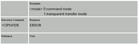
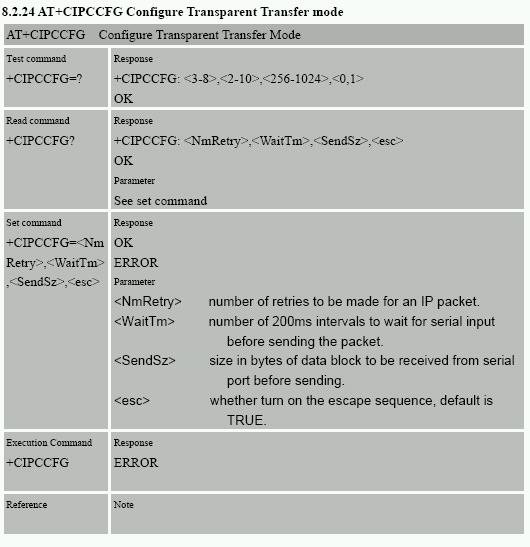
43 The above sample time will be: Time = '3iF' = 03:50:22 The above sample date will be: Date = 'G86' = 23/08/ Serial port data sending using the GSM Modem: Serial port data sending allows any external device to use the tracking units as communication interface. As the tracking unit has the TCP/IP protocol build in the external device does not require the protocol to send and receive data using the Internet to or from any location in the world. Simple AT commands are used for all communication. Serial port data sending: Tracking unit must have credits to access the modem using the serial port for SMS and GPRS mode(s). Send "S". (Capital "S") Wait for "OK+<mode - 1 byte>" (mode is 0 when in SMS only mode and 1 if in SMS and GPRS mode) Then send 4 digit password + CR ($0D). Wait for > + CR($0D) + LF($0A). The serial port has now direct access to the GSM modem. Baud speed is set at 9600 and cannot be changed. Only AT commands are allowed, no connection to the internet using dial-up is allowed on this port. The tracking unit will monitor the port for data communication. Type AT COMSTOP or at comstop to disconnect. If no data is send (from the serial port to the modem) for more then 60 seconds the port will automatic disconnect. During connection the tracking unit cannot send or process any data. Please note: In SMS only mode the unit will send all data using SMS. In SMS and GPRS mode the unit will send all data using GPRS. The unit still processes SMS messages when connected to the GPRS network. The unit can process and send SMS messages without disconnecting from the GPRS network. 8. Priority of Messages: As your tracking system processes many inputs and outputs there are several outputs and inputs that have priority above others. In general: Panic Button First Priority All others have the same priority, but reporting of the activation may depend on what input has activated first if several inputs are activated at the same time. This priority setup may delay messages that have less priority. When changing operating mode from 'SMS Only' to 'SMS+GPRS' the current active commands are completed first before changing operating mode. 43
44 - 44-9a. Basic testing and problem solving: B asic Testing S equence NO Check Battery Check Power Switch ON! Check SIM card Connect Battery Charge Cable P T35 is in D eep sleep m ode A ny LE D s on or Falshing? YES Yellow LED Flashing? YES NO If Y E LLO W LE D is not flashing then there is N O G S M S IG N A L or P T35 is in S leep m ode. E N D P hone the unit num ber E N D Ring TONE? YES Connect communication (charger cable) and download current settings. See Manual for correct settings and com m unication NO S IM card is faulty or not registered on the network. SIM PIN number is different from the configuration setting. Remove SIM PIN number or set to 0000 Test S IM card in norm al GSM phone. E N D E N D 44
45 - 45-9b. Motion Alert flow chart: M otion A lert C an be enabled by configuration setting, S M S com m and or by sw itch E X IT NO E nabled YES M ovem ent/v ibration detected YES NO NO N o m ovem ent/v ibration detected for m ore then 1 m inute YES NO S ound B uzzer B uzzer activate for m ore then 30 seconds YES NO M ovem ent/v ibration detected YES S end M otion alert m essage. D eactivate m otion alert enabled. The M otion alert can be enabled again by S M S m essage, configuration m enu settings or by using the P ark sw itch (if configured for m otion alert). The P ark sw itch m ust be turned off and turned on again to enable M otion alert again. 45
46 - 46-9c. Park Alert flow chart: P ark Function E X IT NO E nabled D elay 60 S econds YES M ovem ent/v ibration D etected NO M ore then 3 Tim es w ithin 30 S econds NO NO S peed m ore then 5km /h YES YES A ctivate P ark A larm. Send Park alarm m essage. 46
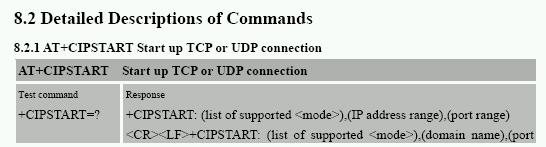
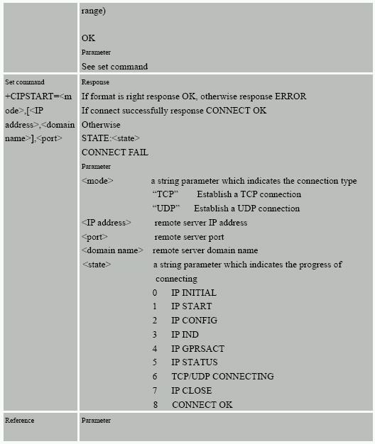
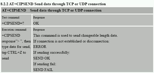
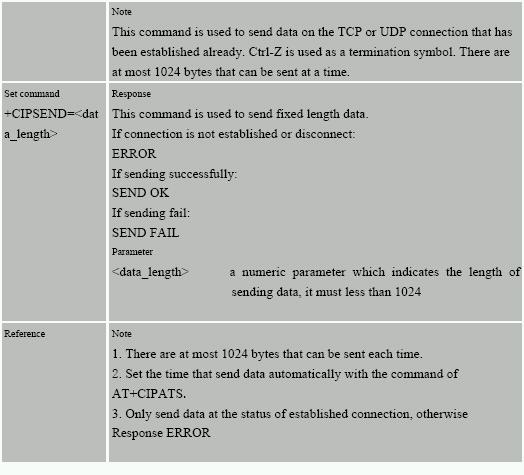
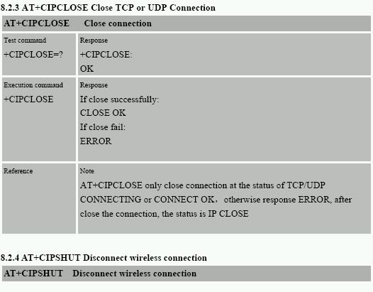
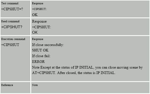
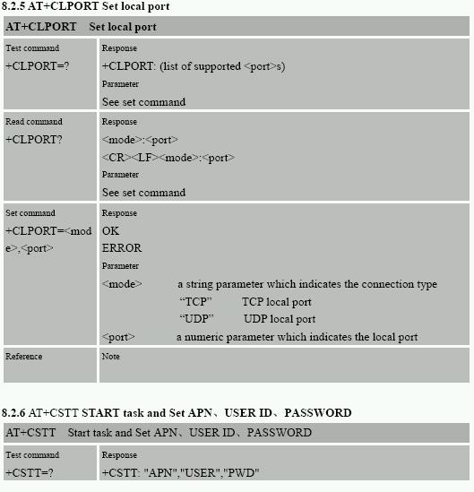
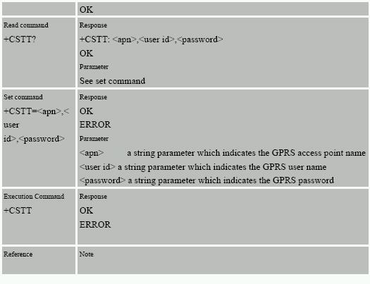
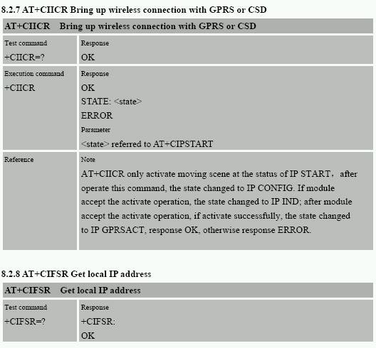
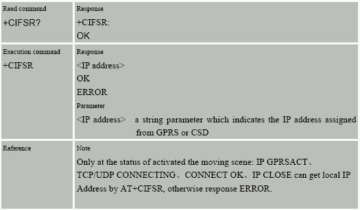
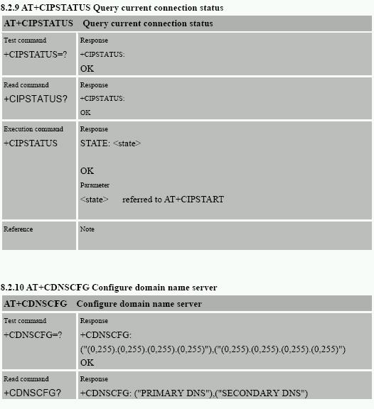
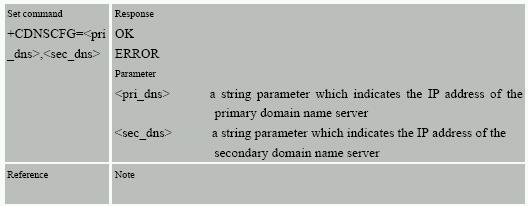
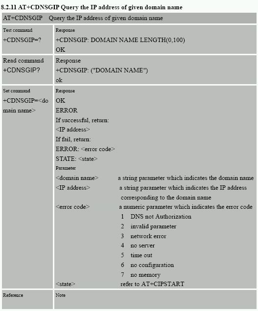
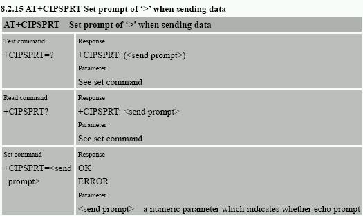
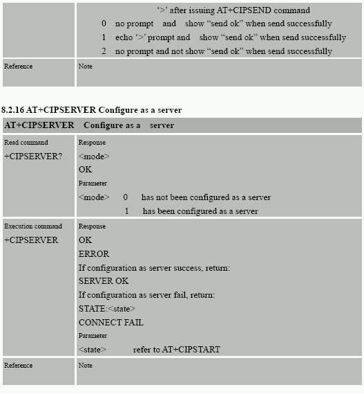
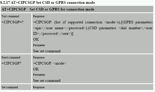
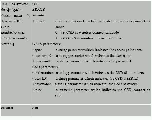
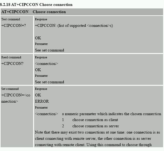
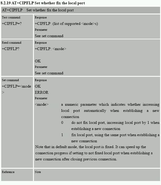
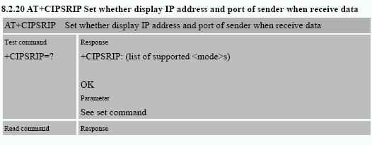
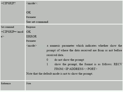
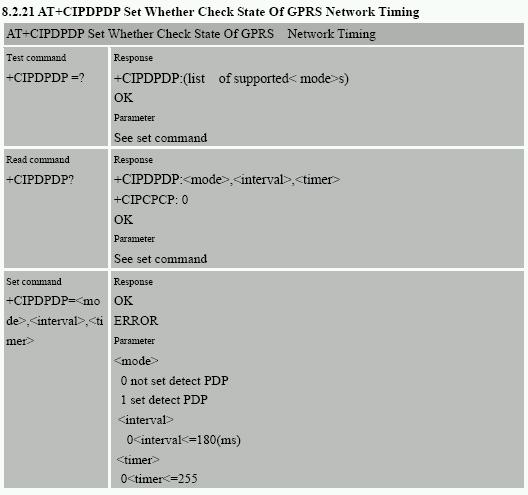
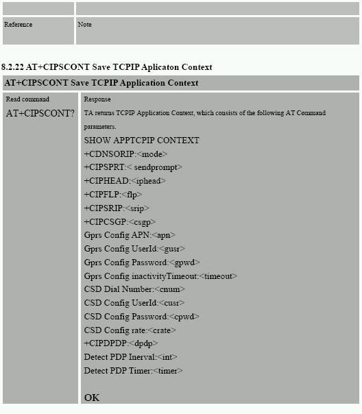
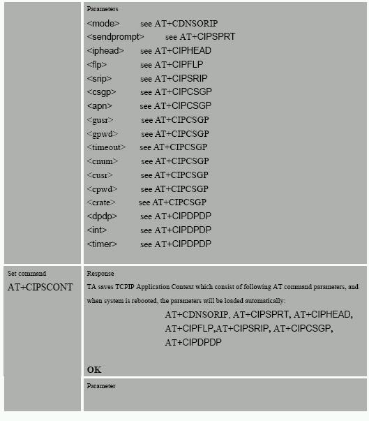
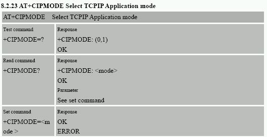
47 GPRS TESTING Using the direct connection to the GSM modem (in test mode under Hyperterminal). 1. Check GSM signal AT+CSQ <Enter> Example: +CSQ: 21,0 2. Check SIM card registered AT+CREG? Example: +CREG:0,1 (registered Home network) 3. Check network connected AT+COPS? Example: +COPS: 0,0,"CHINA MOBILE" 4. Set APN ( AT + CSTT ) AT + CSTT = APN [, ID, password ] Ex. at + cstt = internet <Enter> (Chun Huw,TCC) at + cstt = FETNet01 <Enter> (FET) 5. Attach to GPRS network ( AT + CIICR ) AT + CIICR <Enter> 6. Get local IP address assign by GPRS Network(AT + CIFSR) AT + CIFSR <Enter> 7. Start TCP/UDP connection ( AT+CIPSTART ) AT + CIPSTART = Mode, IP, Port Mode =TCP or UDP IP =remote server IP address Port =remote server port Example. at + cipstart = TCP, , DATA Send ( AT+CIPSEND ) <Enter> AT + CIPSEND <Enter> (Send data out by Ctrl-z ) >DATA Ctrl Z AT + CIPSEND = <length> <Enter> (setup Length of data and send out automatically) 9. Close connection( AT + CIPCLOSE ) AT + CIPCLOSE <Enter> 10. Shut down connect ( AT + CIPSHUT ) AT+CIPSHUT<Enter> (Enter at comstop to return to main menu) 47

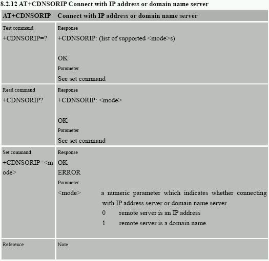
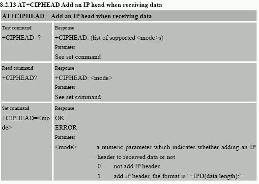
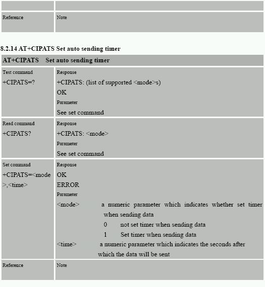
48 AT COMMANDS FOR GPRS SUPPORT Detailed Descriptions of commands AT Commands For (TCP/UDP) 48
49
50
51
52
53
54
55
56
57
58
59
60
61
62
63
64
65 Receiving and sending GPRS data: The GPRS data format for sending is identical to the message format sent using SMS except that the GPRS has a header string at the start off the message. This is for all GPRS data including the CONFIRM and multiple location message. The header string is the IMEI number from the tracking unit GSM modem. The IMEI number is displayed on the tracking unit or is shown when you exit the diagnostic main menu using Hyperterminal. Sample data string received in GPRS mode (without compression): <IMEI number>,05*850,000,pt35,a, ,n, ,e,000.0,224.8,00.8,07:47: ,1.00,80,3F Sample data string received in GPRS mode (with compression): <IMEI number>,05*850000pt35a n e f Any command message(s) can also be sent to the tracking unit in GPRS mode. The message(s) must be sent within 2 seconds after any message is received in GPRS mode. The command messages as identical to the messages sent using SMS. GPRS errors: The serial port will output GSM communication and any errors when connection or sending data in GPRS mode. 65
66 WGAT Connections: The WGAT has one multi I/O connector to connect external devices. The user serial port and charger cable will connect to this connector. There are several other I/O pins that allow the WGAT to be used for other applications. Front View Pin1 Pin18 Pin Out: Pin Name Function 1 Vpp External input power. Must be between 4 and 4.7 Volt(Max) DC up to 1A. * Internal battery must be removed! 2 Vcpu Power output 3.3Volt/DC 50mA max (for ADC power) 3 Park Park switch. To activate connect to ground. 4 AUX1 Digital input AUX1 (Max +60Vdc). To activate connect to ground. 5 AUX2 Analog input. This input is NOT protected so care must be taken before using this input. Power input between 0 and 3.3VoltDC max. We recommend to use Vcpu as power supply. Can be used to measure temperature. 6 Loop1 Loop connection1 (See Connecting the Wire loop cable ) 7 Loop2 Loop connection2 (See Connecting the Wire loop cable ) 8 Panic Panic input. Connect to ground or loop2/loop1 to activate 9 Vin Battery charge input power. Must be +5Volt/ 500mA 10 Vin Battery charge input power. Must be +5Volt/ 500mA 11 Serial In Serial port input 9600 Baud 12 Serial Out Serial port output 9600 Baud 13 Speaker + External positive Speaker connection 8 Ohm /1.2 Watt max output 14 Speaker - External negative Speaker connection 8 Ohm /1.2 Watt max output 15 GND Ground 16 GND Ground 17 MIC - External negative microphone connection 18 MIC + External positive microphone connection 66
67 I/O cable pin out for WGAT: The picture below shows the WGAT I/O cable.. Pin Out: Pin Name Color 1 External input power 4~ 4.7 Volt(Max) DC / 1A. Black 2 Power output 3.3Volt DC 50mA Max Brown 3 Park switch Red 4 Digital input AUX1 (Max +60Vdc) Orange 5 Analog input or Digital output 0 ~3.3Volt DC only (AUX2) Yellow 6 Loop1 Green 7 Loop2 Blue 8 Panic input Purple Battery charge input power+5volt/ 1A Ground Grey White 67
 at 25 degrees. So in our example that will be 10K. The input voltage to AUX2 will then be 1.")
68 Measuring temperature (NTC) using the AUX2 input example: The AUX2 input voltage (yellow wire) will change when the temperature changes. Most Thermistors are at normal resistance (in above example we use 10 K) at 25 degrees. So in our example that will be 10K. The input voltage to AUX2 will then be 1.27 Volt (ADC value will be 128 decimal or 80 hex). The input voltage is always included in the location message and can be configured to activate below or above set value. Using the WGAT I/O cable the AUX2 input must be connected to the yellow wire, the GND to the white wire and the Vcpu to the Brown wire. 68

69 Measuring temperature (DS18S20) using the AUX2 input example: When the DS18S20 is connected as shown above and enabled in the configuration menu program the temperature measured is automatic included in every location message. The WGAT will measure the temperature when running in normal running mode every few seconds. When the temperature trigger is activated a location message will be send with the temperature measured and the activation status. The temperature trigger will deactivate once the temperature goes back and stay between the low and high trigger value and automatic reactivate again once the temperature goes again below or above the trigger value configured. During sleep mode no temperature measurement will be done and cannot activate in sleep mode. Please note that the battery consumption will be more then using the DS18S20 to measure the temperature. Measures temperatures from 55 C to +125 C ( 67 F to +257 F) +/- 0.5 degree accurate Example location message data with positive temperature: 05*850,@00,PT35,A, ,N, ,E,000.0,224.8,00.8,07:47: ,1.00,80,36 Shows temperature trigger activated with temperature at 36 (HEX). The temperature value needs to be converted depending on positive or negative value. In the above sample the temperature is positive (status code digit 3 is zero and the temperature is 36 hex = 54/2 = 27 degrees Example location message data with negative temperature: 05*850,@08,PT35,A, ,N, ,E,000.0,224.8,00.8,07:47: ,1.00,80,CE Shows temperature trigger activated with temperature at CE (HEX). The temperature value needs to be converted depending on positive or negative value. In the above sample the temperature is negative (status code digit 3 is 8 and the temperature is CE hex = 206 -> ( )/2 = - 25 degrees Testing the DS18S20 connection can be done when the WGAT enters normal running mode (when you exit the diagnostic mode using Hyper terminal). When pressing the T or t key the WGAT will display the temperature measured by the DS18S20. The DS18S20 temperature test will exit automatic after 60 seconds or when you press the Q or q key. PLEASE NOTE THAT THE TESTING OPTION CAN ONLY DISPLAY THE CORRECT TEMPERATURE FOR ZERO (00) to MAX 99 DEGREES. This is only limited for the testing option. Temperature shown in the location message can be from 55 to +125 Degrees. The complete datasheets for DS18S20 can be downloaded from the maxim web site ( Using the WGAT I/O cable the AUX2 input must be connected to the yellow wire, the GROUND to the white wire and the 3.3Volt to the Brown wire. The cable length is limited to 2 meters max. 69
GPS Tracker AT06 manual Ver
 GPS Tracker AT06 manual Ver 1.0 20130924 Released 1 / 15 Content 1. Product Over View... 3 2. Features and Specification... 3 2.1 Features... 3 2.2 Specification... 4 2.3 GSM/GPS/Power Led identification...
FIFOTRACK PARAMETER TOOL USER GUIDE V1.1
 FIFOTRACK PARAMETER TOOL USER GUIDE V1.1 Copyright 2015 fifotrack All rights reserved 1 Copyright and Disclaimer: All copyrights belong to Shenzhen fifotrack Solution Co., Ltd. You are not allowed to revise,
GPS Vehicle and personal location tracker
 Version Number Modified by Change Content Type Date V1.0 Amy create 2014.06.23 GPS Vehicle and personal location tracker User Manual GPS Vehicle and personal location tracker User Manual 1 Contents 1.
GPS Vehicle and personal location tracker
 Version Number Modified by Change Content Type Date V1.0 Amy create 2014.06.23 GPS Vehicle and personal location tracker User Manual GPS Vehicle and personal location tracker User Manual 1 Contents 1.
KDG27. GPS Tracker. Vehicle or Personal Position Tracking Vehicle Status and Speed Tracking. Auto Accident Report Global Position System (GPS)
") Vehicle or Personal Position Tracking Vehicle Status and Speed Tracking Auto Accident Report Global Position System (GPS) Navigation System Anti-theft Alarm System Overview 1. GPS data tracking via GSM
Vehicle or Personal Position Tracking Vehicle Status and Speed Tracking Auto Accident Report Global Position System (GPS) Navigation System Anti-theft Alarm System Overview 1. GPS data tracking via GSM
Vehicle and personal location tracker
 Version Number Modified by Change Content Type Date V1.0 Amy create 2016.08.28 GPS Vehicle and personal location tracker User Manual GPS Vehicle and personal location tracker User Manual Version Number
GPS Vehicle and personal location tracker. User manual
 GPS Vehicle and personal location tracker User manual 1 Contents 1. Product overview... 2 2. Safety instruction... 3 3. Specification and parameters... 3 4. Getting started... 4 4.1 Hardware and accessories...
: DOOR ENTRY UNIT USER MANUAL EIS-LCD. Programming Software
 : DOOR ENTRY UNIT EIS-LCD Programming Software v.2.0 2018 Page 1 Contents 1 FOR YOUR SAFETY...5 2 INTRODUCTION...6 3 EIS-LCD, EIS-40 FEATURES AND APPLICATIONS...7 4 START UP...8 5 LED INDICATION...9 6
MT550 Cat M1/NB1 GPS Tracker User Manual V2.0
 MT550 Cat M1/NB1 GPS Tracker User Manual V2.0 Preface Congratulations on choosing the Mictrack MT550 Cat M1/NB1 GPS tracker. This manual shows how to easily program and setup the tracker for best results.
USER MANUAL V5.0 GT60
 GPS Tracker USER MANUAL V5.0 GT60 Updated on 26/12/2008 Contents 1 Product Overview 3 2 For Your Safety 3 3 GT60 Parameters 3 4 Getting Started 4 4.1 Hardware and Accessories 4 4.2 Light and Button Functionality
Ready Track OBD Vehicle Tracker
 Ready Track OBD Vehicle Tracker VX60 User Guide Copyright 2013 Ready Track Pty Ltd. All rights reserved. -1- Contents 1. Notice... 3 1.1 Usage Information... 3 1.2 Product Accessories... 3 2. Product Function
: DOOR ENTRY UNIT. Programming Software USER MANUAL
 : DOOR ENTRY UNIT Programming Software MODELS: EIS-1, EIS-2 OR EIS-4 v.02 2018 Contents 1 FOR YOUR SAFETY...4 2 INTRODUCTION...5 3 EIS-1, EIS-2, EIS-4 FEATURES AND APPLICATIONS...6 4 START UP...7 5 LED
GPS Personal Tracker User Manual V1.0 GT601
 www.autoleaders.gr GPS Personal Tracker User Manual V1.0 GT601 Contents 1.Product Overview... -2-2.For Your Safety... -3-3.GT601B Characteristics... - 3-4.Getting Started... -4-4.1 Hardware and Accessories...
GC-101 GPS / GSM Micro Tracker
 GC-101 GPS / GSM Micro Tracker Table of Contents 1. Hardware Description...4 1.1 Front Face...4 1.2 Side Face...4 1.3 Bottom Face...6 1.4 Charging...6 1.5 Rear Face (Battery Cap)...7 2. Specifications...8
Gator Watch. User Guide
 Gator Watch User Guide 1. Getting Started... 1 1.1 What is Gator... 1 1.2 Features... 1 1.3 Activating Gator... 1 1.4 Charging Gator... 2 1.5 Getting Help... 2 2. Gator Controls... 2 2.1 Right Side Buttons...
CCTR-628 Long Standby Time GPS Tracker Using Guide
 CCTR-628 Long Standby Time GPS Tracker Using Guide -201811 Welcome to use this Long standby time GPS tracker CCTR-628. Customers are free to track their belongings anytime anywhere. It s built in rechargeable
MEITRACK MVT340 User Guide
 MEITRACK MVT340 User Guide Change History File Name MEITRACK MVT340 User Guide Created By Kyle Lv Project MVT340 Creation Date Update Date 2010-08-24 2017-03-23 Subproject User Guide Total Pages 12 Version
ZD-VT1 User Guide. ZENDA GPS Tracker ZD-VT1 User Guide
 ZENDA GPS Tracker ZD-VT1 User Guide Change History File Name ZD-VT1 User Guide Created By Kyle Lv Product ZD-VT1 Creation Date 2016-01-08 Update Date 2016-02-02 Subproject User Guide Total Pages 16 Version
SOLO NX EXT COMPACT GSM DOOR ENTRY UNIT WITH 1, 2 or 4 CALL BUTTONS
 SOLO NX EXT COMPACT GSM DOOR ENTRY UNIT WITH 1, 2 or 4 CALL BUTTONS Contents 1 FOR YOUR SAFETY... 3 2 INTRODUCTION... 4 3 SOLO-NX FEATURES AND APPLICATIONS... 5 4 START UP... 6 5 LED INDICATION... 7 6
GSM/GPRS/GPS TRACKER USER MANUAL
 GSM/GPRS/GPS TRACKER USER MANUAL Thank you for purchasing the tracker. This manual shows how to operate the device smoothly and correctly. Make sure to read this manual carefully before using this product.
Haicom HI-604 GPS Tracking Device with 5-years Standby Battery
 Haicom HI-604 GPS Tracking Device with 5-years Standby Battery INTRODUCTIONS: This is a multi-function state-of-the-art GPS tracking solution offering you a 4 in 1 solution GPS/GSM/GPRS/SMS/DTMF all in
USER GUIDE. Personal/Asset/Pet GPS TRACKING SYSTEM. Thank you for using GPS Tracking system. This device is an innovative miniature size
 USER GUIDE Personal/Asset/Pet GPS TRACKING SYSTEM Product Overview Thank you for using GPS Tracking system. This device is an innovative miniature size personal remote positioning device with built in
SOLO KP SOLO KP LCD COMPACT MULTI-APARTMENT GSM DOOR ENTRY UNIT USER MANUAL
 SOLO KP SOLO KP LCD COMPACT MULTI-APARTMENT GSM DOOR ENTRY UNIT Contents 1 FOR YOUR SAFETY... 4 2 INTRODUCTION... 5 3 SOLO-KP AND SOLO-KP LCD FEATURES AND APPLICATIONS... 6 4 START UP... 7 5 LED INDICATION...
FERGUSON BEAUREGARD. RTU-5000 Configurator User Manual
 FERGUSON BEAUREGARD RTU-5000 Configurator User Manual FERGUSON BEAUREGARD RTU-5000 Configurator User Manual The Ferguson Beauregard RTU-5000 Configurator program and manuals are Copyright 1997-2004 by
900E Vehicle GPS Tracker User Manual
 Auto leaders 900E Vehicle GPS Tracker User Manual 2009-10-01 1 Table of Contents 1. Working Directions.....3 2. GPS Tracker Installation...3 2.1. Product Parts List...3 2.2. Precaution before Installation...4
MEITRACK T355G/T355 User Guide
 MEITRACK T355G/T355 User Guide Change History File Name MEITRACK T355G/T355 User Guide Created By Vincent Chang Project T355G/T355 Creation Date Update Date 2016-08-23 2017-06-08 Subproject User Guide
USER GUIDE GPS TRACKING SYSTEM
 USER GUIDE GPS TRACKING SYSTEM - 1 - Product Overview Thank you for purchasing TE 207S. This device is a waterproof IPX6, innovative miniature size personal remote positioning device with built in U blox
Vehicle GPS Tracker (GSM+GPS+SMS/GPRS) TS10 User Manual (Version 1.1)
 TS10 User Manual (Version 1.1)") Vehicle GPS Tracker (GSM+GPS+SMS/GPRS) TS10 User Manual (Version 1.1) IndexContents 1. Package Contents... 3 2. Features and Specifications...3 3. Knowledge before Usage... 3 3.1 Factory Default Setting...
Vehicle GPS Tracker (GSM+GPS+SMS/GPRS) TS10 User Manual (Version 1.1) IndexContents 1. Package Contents... 3 2. Features and Specifications...3 3. Knowledge before Usage... 3 3.1 Factory Default Setting...
MEITRACK T333 User Guide
 MEITRACK T333 User Guide Change History File Name MEITRACK T333 User Guide Created By Owen Cheng Project T333 Creation Date Update Date 2014-06-10 2017-04-06 Subproject User Guide Total Pages 16 Version
QUICK GUIDE. Publication number PEBBELL_v2_V9.1_ QUICK GUIDE HOIP TELECOM, 2016
 QUICK GUIDE Publication number PEBBELL_v2_V9.1_4402.1625 QUICK GUIDE HOIP TELECOM, 2016 1GETTING TO KNOW YOUR DEVICE STARTING PEBBELL 2 1 STARTING PEBBELL 2 2DEVICE CHARGING The Pebbell v2 device is equipped
GSM communicator GD-06 Allegro Complete manual
 GSM communicator GD-06 Allegro Complete manual The GD-06 ALLEGRO is a universal GSM dialer and controller. It can be used for both home and industrial automation purposes, for security applications or
FIFOTRACK VEHICLE GPS TRACKER. Model: S30 Version: V1.1
 FIFOTRACK VEHICLE GPS TRACKER Model: S30 Version: V1.1 www.fifotrack.com Copyright and Disclaimer All copyrights belong to Shenzhen fifotrack Solution Co., Ltd. You are not allowed to revise, copy or spread
USER MANUAL FOR GS100/GS1003G
 USER MANUAL FOR GS100/GS1003G 1 Table of Contents 1. INTRODUCTION... 3 2. FEATURES... 3 3. OPERATION... 3 4.CONNECTION DETAILS... 4 5.CONFIGURATION... 5 5.1 Hyper Terminal Setting... 5 5.2 GS100 Configuration...
FIFOTRACK MOTORCYCLE/VEHICLE GPS TRACKER
 FIFOTRACK MOTORCYCLE/VEHICLE GPS TRACKER Model: S20 Version: V1.1 www.fifotrack.com Copyright and Disclaimer All copyrights belong to Shenzhen fifotrack Solution Co., Ltd. You are not allowed to revise,
LIFE ALARM GPS SMART TRACKER
 LIFE ALARM GPS SMART TRACKER GPS TRACKING SYSTEM INSTRUCTION MANUAL Product Overview - 1 - Thank you for purchasing Life Alarm 's Personal GPS SOS Tracker. This device is a waterproof IPX66, innovative
ST-908 User Manual GPS Vehicle Tracker
 ST-908 User Manual GPS Vehicle Tracker 2016-09-01 1 Quick Start to test tracker: 1. Put the SIM Card in the tracker. 2. Connect the GPS and GSM antenna. 3. Connect the 4 pin and 6 pin wires. 4. Connect
TR-206 User Manual. Version 1.0
 TR-206 User Manual Version 1.0 TR-206 page 2 CONTENT 1 Safety... 4 2 TR-206 Introduction... 6 Brief Introduction...6 Features...6 3 Specifications... 8 Hardware Specifications...8 4 Getting Started...
LT2400 GPS TRACKER. GSM 2G Use only Vodafone SIM cards (Do not use 4G data only SIMs)
") LT2400 GPS TRACKER GSM 2G Use only Vodafone SIM cards (Do not use 4G data only SIMs) Included; 1 x GPS tracker with built-in magnets 1 x mains/usb charger This manual A free APP for your mobile phone -
LT2400 GPS TRACKER GSM 2G Use only Vodafone SIM cards (Do not use 4G data only SIMs) Included; 1 x GPS tracker with built-in magnets 1 x mains/usb charger This manual A free APP for your mobile phone -
GeoSIM Global SIM Card User Guide IMPORTANT PLEASE READ BEFORE INSERTING YOUR SIM CARD
 GeoSIM Global SIM Card User Guide IMPORTANT PLEASE READ BEFORE INSERTING YOUR SIM CARD Thank you for purchasing GeoSIM, a global GSM service for mobile phones. GeoSIM can reduce your mobile roaming charges
TrackingTheWorld.com. CAT-200X Ankle Tracker Tracking Device USER MANUAL
 TrackingTheWorld.com CAT-200X Ankle Tracker Tracking Device USER MANUAL Document Title Compliance Ankle Tracker User Manual Version 2.0 Date 2017-09-16 Status Document Control ID Release TTW-CAT200X-UM002
NAVIXY M7 Protocol Document Version: 1.04 Date:
 NAVIXY M7 Protocol Document Version: 1.04 Date: 2010-07-11 General Notes: All materials contained on this documentation is protected by the copyright law and may not be reproduced, transmitting, published
The Packs Infotel. GSM Converter V2. Installation Manual V7
 The Packs Infotel GSM Converter V2 Installation Manual V7 1 Index Connecting the M60 to the GSM Converter 3 1. GSM Converter description 4 2. Equipment installation 4 3. Led functions. 5 4. GSM Converter
Indicator Status Instruction as follower:
 GSM remote camera User manual 1. The GSM SIM card for GSM camera should be PIN code de-activated, and it needs to activate caller ID presentation & MMS functions. 2. Be sure to remember and keep the product
GPS Watch Tracker USER MANUAL. (Model: WT100)
") GPS Watch Tracker USER MANUAL (Model: WT100) ELECTRONICS TECHNOLOGY LIMITED Address: Room2007, Tower B, Gaoke Building, Tianhe North Road, Guangzhou, China. Tel: (+86)20-38351400, 38351401 Fax: (+86)20-38351400
GPS Watch Tracker USER MANUAL (Model: WT100) ELECTRONICS TECHNOLOGY LIMITED Address: Room2007, Tower B, Gaoke Building, Tianhe North Road, Guangzhou, China. Tel: (+86)20-38351400, 38351401 Fax: (+86)20-38351400
: DOOR ENTRY UNIT USER MANUAL EIS-R. Programming Software. v
 : DOOR ENTRY UNIT EIS-R Programming Software v.1.4.20161115 Contents 1 FOR YOUR SAFETY...3 2 INTRODUCTION...4 3 EIS-R FEATURES and APPLICATIONS...5 4 START UP...6 5 LED INDICATION...7 6 CONNECTION DIAGRAM...8
SRT278 AVANT Fleet Binary Protocol Specification
 SRT278 AVANT Fleet Binary Protocol Specification Version: 1.2.4 Date: June 2012 Scandinavian Radio Technology AB www.srt.se Box 23, 162 11 Vällingby, Sweden Table of Contents Binary Communication Protocol...
CCTR-622G 2G/3G(WCDMA) Tracker User Manual
 Tracker User Manual") CCTR-622G 2G/3G(WCDMA) Tracker User Manual Welcome to use this personal tracker. This product is with GSM/WCDMA module, that has many new and unique functions, such as super power saving technology, real
CCTR-622G 2G/3G(WCDMA) Tracker User Manual Welcome to use this personal tracker. This product is with GSM/WCDMA module, that has many new and unique functions, such as super power saving technology, real
Tracker in Motion from BMS User Manual
 Tracker in Motion from BMS User Manual GL100 GPS-GSM Tracking Device 2011 BMS, Inc Melbourne, FL USA 1 Contents Tracker in Motion from BMS User Manual...1 Contents...2 Contents of Package...3 Buttons and
Instruction Manual. Fall Detection GPS Locator - 2-way Voice Calls. Keep track of your loved ones
 Instruction Manual Fall Detection GPS Locator - 2-way Voice Calls Keep track of your loved ones 1 Index Subject Page Overview... 3 Sosbuddy - Choice of Colours... 4 1 Setting Emergency Contact Numbers...
: DOOR ENTRY UNIT USER MANUAL EIS-LCD. Programming Software. v
 : DOOR ENTRY UNIT EIS-LCD Programming Software v.1.4.20161115 Page 1 Contents 1 FOR YOUR SAFETY...4 2 INTRODUCTION...5 3 EIS-LCD, EIS-40 FEATURES and APPLICATIONS...6 4 START UP...7 5 LED INDICATION...8
Enterprise Edge 2.0 Voice Messaging Set Up and Operation Guide
 Enterprise Edge 2.0 Voice Messaging Set Up and Operation Guide www.nortelnetworks.com 2000 Nortel Networks Contents Chapter 1 Introduction 13 About Enterprise Edge Voice Messaging 13 Basic Enterprise Edge
GPS Personal Tracker
 GPS Personal Tracker User Manual (Model: PT30) Please Read Carefully Before Operation - 1 - Contents 1. Product Overview------------------------------------------------------------------------------------------3
The JA-80Y GSM communicator
 CANCEL MENU NAMES CALLS WRITE READ SPACE The communicator is a component of the Jablotron Oasis 80 system. It is designed to be installed within the control panel housing. When connected to a GSM network
User Manual Revision 1.02
 User Manual Revision 1.02 Manufactured by Contents 1. Introduction... 4 2. Disclaimer and Warranty... 4 3. Specifications... 5 4. Features... 5 5. Quick Start Guide... 6 5.1 Hardware... 6 5.2 Software...
GPS Motorcycle/Vehicle Tracker USER MANUAL. (Model: TK668)
") GPS Motorcycle/Vehicle Tracker USER MANUAL (Model: TK668) GUANGZHOU TOPTEN ELECTRONICS FACTORY Address: 20/F, Tower B, Gaoke Building, Tianhe North Road, Guangzhou, China. Tel: (+86)20-38351400, 38351401
GPS Motorcycle/Vehicle Tracker USER MANUAL (Model: TK668) GUANGZHOU TOPTEN ELECTRONICS FACTORY Address: 20/F, Tower B, Gaoke Building, Tianhe North Road, Guangzhou, China. Tel: (+86)20-38351400, 38351401
RST200. Configuration & Beam Management System Manual
 RST200 Configuration & Beam Management System Manual Beam Communications Pty Ltd 1 RST200 Configuration & Beam Management System Manual Beam Communications Pty Ltd 8 Anzed Court, Mulgrave, Victoria, 3170,
Gemalto EHS6T-USB Terminal Starter Kit. Getting Started Guide
 Gemalto EHS6T-USB Terminal Starter Kit Getting Started Guide EHS6T-USB Terminal Starter Kit Contents Image is for a Kit A version. Other versions with different antenna may be available. This manual is
: DOOR ENTRY UNIT USER MANUAL. Programming Software. v
 : DOOR ENTRY UNIT Programming Software MODELS: EIS-1, EIS-2 OR EIS-4 v.1.4.20161115 Contents 1 FOR YOUR SAFETY...3 2 INTRODUCTION...4 3 EIS-1, EIS-2, EIS-4 FEATURES and APPLICATIONS...5 4 START UP...6
InTimeGo-630 GPS Watch Tracker User Manual
 InTimeGo-630 GPS Watch Tracker User Manual Product: CCTR-630 Watch 1 set, Mini USB Charging Wire, Manual (CD or Print), AC Charger (Optional), Water-proof Bag for Pets Belt(Optional). Charging ON/OFF SOS
GSM/GPS Car Tracking Terminal USER MANUAL CAT-3D. Ver:
 GSM/GPS Car Tracking Terminal USER MANUAL CAT-3D Ver:2.01 2011-03-02 CONTENTS CAT3D_V1-NB_1.hex INTRODUCTION---------------------------------------------------------------2 Functions and Features------------------------------------------------2
SS-10 3G USER MANUAL FIXED CELLULAR TERMINAL. DOC. NO: SS-10 3G-14 (Rev. 01) Page 1 of 20
 Page 1 of 20") SS-10 3G FIXED CELLULAR TERMINAL USER MANUAL DOC. NO: SS-10 3G-14 (Rev. 01) Page 1 of 20 Revision History: Revision 01 Original document 12 August 2010 CONTENTS 1 INTRODUCTION...3 2 FEATURES...4 2.1 PHYSICAL
SS-10 3G FIXED CELLULAR TERMINAL USER MANUAL DOC. NO: SS-10 3G-14 (Rev. 01) Page 1 of 20 Revision History: Revision 01 Original document 12 August 2010 CONTENTS 1 INTRODUCTION...3 2 FEATURES...4 2.1 PHYSICAL
Cinterion BGS2T (RS232) Terminal Starter Kit. Getting Started Guide
 Terminal Starter Kit. Getting Started Guide") Cinterion BGS2T (RS232) Terminal Starter Kit Getting Started Guide BGS2T (RS232) Terminal Starter Kit Contents PLEASE NOTE KIT CONTENTS MAY VARY ACCORDING TO ORIGIN AND THE INTENDED COUNTRY OF OPERATION
Cinterion BGS2T (RS232) Terminal Starter Kit Getting Started Guide BGS2T (RS232) Terminal Starter Kit Contents PLEASE NOTE KIT CONTENTS MAY VARY ACCORDING TO ORIGIN AND THE INTENDED COUNTRY OF OPERATION
C O N T E N T (CLICK THE TITLE AND JUMP TO THE CONTENT)
") GPS/GSM/GPRS TRACKER TK-202 USER MANUAL Preface Thank you for purchasing the GPS Tracker. This manual shows how to operate the device smoothly and correctly. Make sure to read this manual carefully before
GPS/GSM/GPRS TRACKER TK-202 USER MANUAL Preface Thank you for purchasing the GPS Tracker. This manual shows how to operate the device smoothly and correctly. Make sure to read this manual carefully before
CEL MeshConnect ZICM35x Test Tool User Guide
 User Guide 0011-00-17-02-000 CEL MeshConnect ZICM35x Test Tool User Guide CEL MeshConnect ZICM35x Test Tool User Guide Introduction CEL s MeshConnect EM357 Mini Modules combine high performance RF solutions
U-FLASH Setup Guide U-FLASH.
 U-FLASH Setup Guide Thank you for purchasing the U-FLASH. This guide will assist you in the setup of the system. You can call for FREE technical support to get help anytime at 757-258-0910. Please note,
MobilTherm 2ad. 1. How the interface works: GSM temperature alarm module with auxiliay inputs and relay outputs
 MobilTherm 2ad GSM temperature alarm module with auxiliay inputs and relay outputs The MobilTherm-2ad is a GSM temperature and remote signaling module, designed for GSM based remote control, remote signal.
Accen Technology Co., Limited. GPS Tracker Price List (FOB Shenzhen, China)
") Accen Technology Co., Limited http://www.accenhk.com; Tel: 0086-755-27808569; Mobile Phone: 0086-15889506340 Attn.: Mr Andy Wan; Email: andy@accenhk.com; MSN: everestvip@hotmail.com; Skype: accentek GPS
Accen Technology Co., Limited http://www.accenhk.com; Tel: 0086-755-27808569; Mobile Phone: 0086-15889506340 Attn.: Mr Andy Wan; Email: andy@accenhk.com; MSN: everestvip@hotmail.com; Skype: accentek GPS
MEITRACK TC68S/TC68SG User Guide
 MEITRACK TC68S/TC68SG User Guide Change History File Name MEITRACK TC68S/TC68SG User Guide Created By Kyle Lv Project TC68S/TC68SG Creation Date Update Date 2013-03-15 2017-11-09 Subproject User Guide
TR-151A / TR-151E Vehicle/Asset Tracker User Manual. Version 2.3
 TR-151A / TR-151E Vehicle/Asset Tracker User Manual Version 2.3 Table of Content 1. Introduction and Features... 4 1.1 Introduction...4 1.2 Features...4 1.3 Hardware...5 2. Start-up... 6 2.1 Accessories...6
MEITRACK T1 User Guide
 MEITRACK T1 User Guide Change History File Name MEITRACK T1 User Guide Created By Kyle Lv Project T1 Creation Date 2014-06-10 Update Date 2015-09-30 Subproject User Guide Total Pages 17 Version V2.5 Confidential
GPS Tracker Instruction
 GPS Tracker Instruction Content Part One. Preface Part Two. Specifications Part Three. Installing Part Four. Start to use device Part Five. Detail of functions SMS functions 5.1Basic functions 5.1.1 Get
GSM Voice Active Monitoring OTP-GSM89
 GSM Voice Active Monitoring OTP-GSM89 1 Feature: 1. Voice active monitoring, when detect voice level higher then voice setting sensitivity, the module will send SMS and making call automatically. 2. Can
CCTR-829 GPS Tracker Using Guide
 CCTR-829 GPS Tracker Using Guide Welcome to use this Real Time GPS tracker CCTR-829 with external microphone & SOS button & ACC detect and control uploading location, this product is with GPS module and
FMA1X0, FM11YX FIRMWARE ERRATA
 FMA1X0, FM11YX FIRMWARE ERRATA V0.7 1) INTRODUCTION We are always improving our devices performance, stability and reliability. That s why Teltonika is one of the leading GNSS trackers manufacturers in
Verify that Wi-Fi option is turned on. Swipe down from the top of the screen once by using two fingers, or twice using one finger. Tap > Wi-Fi.
 Troubleshooting I can't find an email using the BlackBerry Device Search app The BlackBerry Device Search app only searches email that is in the BlackBerry Hub. To learn how to add email accounts to the
3G GPS Vehicle Tracker
 3G GPS Vehicle Tracker User Manual PL640 V2-1- Product Picture: Magnet Charging contact point Charging port ON/OFF switch and charging indicator LED Car Adapter and changing Wire Charging board(select
1 / 16. Magnetic and Portable GPS Tracker with Long Battery Life
 1 / 16 Magnetic and Portable GPS Tracker with Long Battery Life 2 / 16 Content 1.INTRODUCTION... 4 2. KEY FEATURES... 4 3. HARDWARE SPECIFICATIONS... 4 4. PRODUCT IMAGE... 5 5. INSTALLATION MANUAL... 5
TR-101 User Manual. Ver 1.14
 User Manual Ver 1.14 Table of Contents 1. Introduction... 3 2. Features... 3 3. Specification... 4 4. Start-up... 5 4.1 Accessories... 5 4.2 Charging the battery... 6 4.3 Install SIM card... 6 5. Hardware
MAGNET T SERIES USER GUIDE
 MAGNET T SERIES USER GUIDE 1. Product Image a. T12 b. T4400 /T8800/T15400 Content of the packaging a. Tracking device b. USB Charging cable c. Screwdriver and screws d. User Guide 2. Installation Manual
InTimeGo-623 Pets GPS Tracker User Manual
 InTimeGo-623 Pets GPS Tracker User Manual Product & Lock Unlock: CCTR-623 tracker 1 set, 1 locking dock, 1 collar, 1 screwdriver, 1 USB Charging Wire, Manual (CD or Print), AC Charger (Optional). Collar
GPS+Glonass Vehicle location Tracker
 GPS+Glonass Vehicle location Tracker User Manual V1.0-1 - Contents 1. Products Overview... 3 2. For Your Safety... 4 3. Characteristics... 4 4. Getting Started... 5 4.1. Hardware and Accessories... 5 4.2.
Verify with your service provider that their Mini SIM card will work with GSM / 3G GSM type modems before purchasing their Mini SIM card.
 ENVIROMUX-AVDS-GSM(-P) GSM Automatic Voice Dialer INSTALLATION AND OPERATION MANUAL INTRODUCTION The ENVIROMUX-AVDS-GSM GSM Automatic Voice Dialer is used to send voice or text GSM or SMS alert messages
User Manual PDUTracker
 User Manual PDUTracker Management Software for PDU Table of Contents 1. Overview... 1 1.1. Introduction... 1 1.2. Features... 1 2. Install and Uninstall... 1 2.1. System Requirement... 1 2.2. Software
Meiligao GPRS Communication Protocol Between GPS Tracker and Server
 Meiligao GPRS Communication Protocol Between GPS Tracker and Server Version 1.47 GT30i GT60 VT300 VT310 Change Version Reason of Change Date V1.00 Initial Document 2005-6-25 V1.01 Addition of Alarms 2006-10-8
Spark Nano Users Manual
 Users Manual Contents of the Box...................... 1 Sign Up for Service...................... 2 LEDS................................... Viewing Data............................ 4 Downloading Data........................
GPRS/SerialGateway. GPRS/Serial Gateway. User Manual
 GPRS/Serial Gateway User Manual 1 TABLE OF CONTENTS SECTION 1 GENERAL INFORMATION...5 1.1 General Information... 5 1.2 Proper Use and Safety Conditions... 6 1.3 Connections and Micro SIM Card Placement...
HUAWEI FT2260 Home Phone Connect Quick Start
 HUAWEI FT2260 Home Phone Connect Quick Start Introduction Top View The figures are only for your reference, the actual shape and color of the product may differ slightly. 7 8 9 10 1 2 3 4 5 6 1 Power on/off
GSM AUTO DIALER WITH IR BEAM DETECTOR
 GSM AUTO DIALER WITH IR BEAM DETECTOR Remote Monitoring & Control using your mobile phone. www.gsm-activate.co.uk MODEL NUMBER IRV2 Page 1 Product Information Our GSM Auto-Dialer is a versatile unit which
Quick Start Guide. Insert Micro SIM into SIM slot
 Quick Start Guide Buddy button. Press for 3 seconds to send SOS SMS and call stored numbers Press once to accept Incoming call Insert Micro SIM into SIM slot Microphone Micro USB used for charging SIM
ProCon GSM INSTALLATION AND APPLICATION MANUAL. ProCon GSM manual. .gsm-komunikatorji.com. for module version 1.4
 informacije in naročila: info@gsm-komunikatorji.com.gsm-komunikatorji.com ProCon GSM INSTALLATION AND APPLICATION MANUAL for module version 1.4 1 Index I. Basic descriptions... 3 II. Steps of installation...
GPRS ADAPTER INSTALLATION AND USER MANUAL. for module version v2.24 and higher
 GPRS ADAPTER INSTALLATION AND USER MANUAL for module version v2.24 and higher Table of contents 1 Main function of the Adapter...3 2 System operation...3 2.1 Transmission through GPRS...4 2.1.1 Router
DATA LOGGER (Version V1.3)
") WYLER AG Im Hölderli CH-8405 WINTERTHUR Switzerland Tel. 0041 (0) 52 233 66 66 Fax. 0041 (0) 52 233 20 53 Homepage: http://www.wylerag.com E-Mail: wyler@wylerag.com Operating instructions DATA LOGGER (Version
WYLER AG Im Hölderli CH-8405 WINTERTHUR Switzerland Tel. 0041 (0) 52 233 66 66 Fax. 0041 (0) 52 233 20 53 Homepage: http://www.wylerag.com E-Mail: wyler@wylerag.com Operating instructions DATA LOGGER (Version
GPS Child Tracking Device User manual
 GPS Child Tracking Device User manual Please read this manual carefully before attempting installation. Pictures are for indication and illustration purposes only. 1. Accessories Please check whether these
WiLARM-ContactID GSM Module Installation Guide Version: 2.0
 Content Main functions and operation of the GSM module... 3 Parts of the module.. 3 Mini USB connector. 4 Terminal contacts.... 4 Power supply. 4 Input.. 4 Prefix numbers... 4 LEDs... 5 LED operation chart
TR-206 User Manual. Version 1.2
 TR-206 User Manual Version 1.2 TR-206 page 2 CONTENT 1 Safety... 4 2 TR-206 Introduction... 6 Brief Introduction...6 Features...6 3 Specifications... 8 Hardware Specifications...8 4 Getting Started...
CCTR-820 Mini Water-proof GPS Tracker Using Guide
 CCTR-820 Mini Water-proof GPS Tracker Using Guide Welcome to use this Real Time mini water-proof GPS tracker CCTR-820, This product is with GPS module and GSM module, It is specially design for motor,
ATL20 ATL30 Automatic transfer switch controller
 I 194 GB 07 07 ATL20 ATL30 Automatic transfer switch controller REMOTE CONTROL SOFTWARE MANUAL Summary Introduction... 2 Minimum resources of the PC... 2 Installation... 2 Activation of the PC-ATL connection...
TW-100. Wearable Watch Tracker User Manual. Ver 1.0
 TW-100 Wearable Watch Tracker User Manual Ver 1.0 Table of Contents Introduction...- 1 - Features...- 1 - Specifications...- 2 - Getting Started...- 3 - TW-100 Device Configuration...- 6 - Operation Mode...-
MP90 4G OBD Tracker. User Manual V1.0. Preface
 MP90 4G OBD Tracker User Manual V1.0 Preface Congratulations on choosing Mictrack MP90 4G OBD GPS tracker. This manual shows how to easily program and setup the tracker for best results. Make sure to read
General GPS Vehicle Tracker. User Manual V1.0
 General GPS Vehicle Tracker User Manual V1.0 Introducing your Device Learn about your device s layout, indications and specifications. 1. Inside the Box Check your product box for the following items: