Dominion PX User Guide Release 1.2
|
|
|
- Frederick Page
- 6 years ago
- Views:
Transcription

1 Dominion PX User Guide Release 1.2 Copyright 2008 Raritan, Inc. DPX-0H-E August

2 Safety Guidelines This document contains proprietary information that is protected by copyright. All rights reserved. No part of this document may be photocopied, reproduced, or translated into another language without express prior written consent of Raritan, Inc. Copyright 2008 Raritan, Inc., CommandCenter, Dominion, Paragon and the Raritan company logo are trademarks or registered trademarks of Raritan, Inc. All rights reserved. Java is a registered trademark of Sun Microsystems, Inc. Internet Explorer is a registered trademark of Microsoft Corporation. Netscape and Netscape Navigator are registered trademarks of Netscape Communication Corporation. All other trademarks or registered trademarks are the property of their respective holders. FCC Information This equipment has been tested and found to comply with the limits for a Class A digital device, pursuant to Part 15 of the FCC Rules. These limits are designed to provide reasonable protection against harmful interference in a commercial installation. This equipment generates, uses, and can radiate radio frequency energy and if not installed and used in accordance with the instructions, may cause harmful interference to radio communications. Operation of this equipment in a residential environment may cause harmful interference. VCCI Information (Japan) Raritan is not responsible for damage to this product resulting from accident, disaster, misuse, abuse, non-raritan modification of the product, or other events outside of Raritan's reasonable control or not arising under normal operating conditions. UL C US LI STED 1F61 I.T.E. To avoid potentially fatal shock hazard and possible damage to Raritan equipment: SYSTEMS SHOULD BE CONFIGURED ONLY BY A KNOWLEDGEABLE PERSON. IT IS ESSENTIAL THAT THIS EQUIPMENT IS CONNECTED TO AN ELECTRICAL SUPPLY THAT HAS A PROTECTIVE GROUND CONDUCTOR
3 Safety Guidelines WARNING: TO ISOLATE THIS EQUIPMENT DISCONNECT POWER SUPPLY PLUG. ATTENTION: AFIN D'ISOLER TOTALEMENT CET APPAREIL DEBRANCHER FICHE D'ALIMENTATION. CAUTION: USE ONLY IN DRY LOCATIONS. ATTENTION: UTILISER UNIQUEMENT DANS DES EMPLACEMENTS SECS. Do not use a 2-wire power cord in any product configuration. Test AC outlets at your computer and monitor for proper polarity and grounding. Use only with grounded outlets at both the computer and monitor. When using a backup UPS, power the computer, monitor and appliance off the supply. The installation socket outlet used for the power supply to this equipment must be installed near the equipment and must be easily accessible. When installing this product, it is essential that the distribution circuit supplying the product is protected by a branch circuit protection device with a maximum rating to suit the product maximum rating. This power distribution unit is intended for power supply provision to equipment only. Secondary (Satellite) power strips shall not be connected to the receptacles This product has been designed to conform to the latest safety requirements. In addition to compliance with standards for general use, it has been factory configured for use in rack mounting environments aiding the installer to provide systems compliant with relevant standards. Provide an earthing connection before the mains plug is connected to the mains. And, when disconnecting the earthing connection, be sure to disconnect after pulling out the mains plug from the mains. iii
4 Contents Safety Guidelines ii Chapter 1 Introduction 1 Product Models...1 Product Photos...1 Zero U Size...1 1U Size...2 2U Size...2 Product Features...3 Package Contents...4 Zero U Products...4 1U Products...4 2U Products...5 Chapter 2 Rack-Mounting the Dominion PX 6 Rack Mount Safety Guidelines...6 Standard Rack Mounting...6 For Zero U Models Using L-Bracket...9 For Zero U Models Using Tool-less Mounting...10 Before You Begin Tool-less Mounting:...10 To Mount...10 Chapter 3 Installation and Configuration 12 Before You Begin...12 Unpack the Dominion PX and Components...12 Prepare the Installation Site...12 Fill Out the Equipment Setup Worksheet...12 Connecting the Dominion PX to a Computer...13 Connecting the Dominion PX to Your Network...14 Configuring the Dominion PX for Network Connectivity...15 Resetting to Factory Defaults...18 Chapter 4 Using the Dominion PX 20 Front Panel...20 Connection Ports...20 Blue LED...21 iv
5 Contents Back Panel...21 Power Cord...21 Outlets...21 LED Display...22 Circuit Breaker...24 Beeper...24 Measurement Accuracy...25 Chapter 5 Using the Web Interface 26 Logging into the Web Interface...26 Log In...26 Change Your Password...29 Using the Web Interface...30 Menus...30 Navigation Path...31 Status Panel...32 Status Messages...34 Unavailable Options...34 Reset to Defaults...35 Refresh...35 Using the Home Window...35 Line Loads Display...36 Circuit Breaker Status...36 Outlets List...37 All Outlets Control...39 Monitoring Line and Circuit Breaker Status...39 Line Details Page...39 Circuit Breaker Details Page...40 Setting Up User Profiles...41 Create a User Profile...41 Copy a User Profile...43 Modify a User Profile...44 Delete a User Profile...44 Set User Permissions Individually...44 Setting Up User Groups...45 Create a User Group...46 Set System Permissions...46 Set Outlet Permissions...48 Copy a User Group...49 Modify a User Group...49 Delete a User Group...50 Setting Up Access Controls...50 Force HTTPS Encryption...50 Configure the Firewall...51 Create Group-Based Access Control Rules...54 Set Up User Login Controls...57 Setting Up a Digital Certificate...60 Create a Certificate Signing Request...61 Install a Certificate...63 v
6 Contents Setting Up External User Authentication...63 Set Up LDAP Authentication...64 Setting Up Outlets and Power Thresholds...66 Set Default Outlet State...67 Set Dominion PX Thresholds...68 Set Outlet Power-Up Sequence...69 Name Outlets...70 Set Outlet Thresholds...71 View Outlet Details...72 Power Cycle an Outlet...73 Turn Outlet On or Off...73 Environmental Sensors...73 Connect Environmental Sensors...74 Map Environmental Sensors...74 Configure Environmental Sensors and Thresholds...77 View Sensor Readings...78 Configuring and Using Alert Notifications...78 Components of an Alert...79 How to Configure an Alert...79 Sample Alerts...86 Setting Up Event Logging...89 Configure Local Event Log...90 View Internal Event Log...92 Configure NFS Logging...93 Configure SMTP Logging...94 Configure SNMP Logging...95 Configure Syslog Forwarding...95 Managing the Dominion PX...96 Displaying Basic Device Information...96 Displaying Model Configuration Information...98 Displaying Connected Users...98 Naming the Dominion PX...99 Modifying the Network Settings Modifying the Communications, Port and Bandwidth Settings Modifying the LAN Interface Settings Setting the Date and Time Configuring the SMTP Settings Configuring the SNMP Settings Resetting the Dominion PX Updating the Firmware Outlet Grouping Identifying Other Dominion PX Units Grouping Outlets Together Controlling Outlet Groups Editing or Deleting Outlet Groups Deleting Outlet Group Devices Chapter 6 Integration 114 Dominion KX KX Manager Application (Dominion KX-I only) vi
7 Contents Associate Outlets with a Target Control a Target's Power Dominion KX-II Paragon II Paragon Manager Application Add a Dominion PX Unit in Paragon II Associate Outlets with a Target Control a Target's Power Control an Outlet's Power Dominion SX Configure a Dominion PX Power Unit on Dominion SX Power Control Check Power Strip Status Dominion KSX CommandCenter Secure Gateway Direct Control from CC-SG Appendix A Equipment Setup Worksheet 125 Appendix B Using the CLP Interface 129 About the CLP Interface Logging into the CLP interface With HyperTerminal With SSH or Telnet Showing Outlet Information Syntax Attributes Examples Turning an Outlet On or Off Syntax Querying an Outlet Sensor Appendix C Using SNMP 135 Enabling SNMP Configure Users for Encrypted SNMP v Configuring SNMP Traps SNMP Gets and Sets The Dominion PX MIB Appendix D Using the IPMI Tool Set 142 Channel Commands authcap <channel number> <max priv> info [channel number] getaccess <channel number> [userid] vii
8 Contents setaccess <channel number> <userid>[callin=on off] [ipmi=on off] [link=on off] [privilege=level] getciphers <all supported> <ipmi sol> [channel] Event Commands <predefined event number> file <filename> LAN Commands print <channel> set <channel> <parameter> Sensor Commands list get <id>... [<id>] thresh <id> <threshold> <setting> OEM Commands A Note About Group Commands Set Power Set Delay Command Get Power On Delay Command Set Receptacle State Command Get Receptacle State Command Set Group State Command Set Group Membership Command Get Group Membership Command Set Group Power On Delay Command Get Group Power On Delay Command Set Receptacle ACL Get Receptacle ACL Set Sensor Calibration Test Actors Test Sensors Set Power Cycle Delay Command Get Power Cycle Delay Command IPMI Privilege Levels Appendix E Event Types 156 Appendix F Specifications 157 Environmental Specifications Dominion PX Serial RJ-45 Port Pinouts Dominion PX Feature RJ-12 Port Pinouts Index 159 viii

9 Chapter 1 Introduction The Dominion PX unit is an intelligent power distribution unit that allows you to reboot remote servers and other network devices and to monitor power in the data center through Raritan's KVM switches and Secure Console Servers. From the office or from anywhere, the Dominion PX unit will power on, power off, or reboot remote equipment, as well as monitor current, voltage, power, and temperature. The Dominion PX offers the ability to recover systems remotely in the event of system failure and/or system lockup. It eliminates the need to perform manual intervention or dispatch field personnel, reduces downtime and mean time to repair, and increases productivity. In This Chapter Product Models...1 Product Photos...1 Product Features...3 Package Contents...4 Product Models The Dominion PX comes in several models that are built to stock and can be obtained almost immediately. Raritan also offers custom models that are built to order and can only be obtained on request. See or your local reseller for a list of available models. Product Photos The Dominion PX comes in Zero U, 1U, and 2U sizes. Zero U Size 1

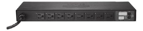
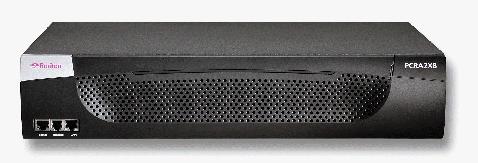
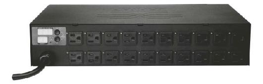
10 Chapter 1: Introduction 1U Size 2U Size 2
11 Chapter 1: Introduction Product Features All models and sizes of the Dominion PX provide the following features: The ability to control outlets collectively and individually The ability to power on, power off, and reboot the devices connected to each outlet The ability to group outlets from multiple Dominion PX as virtual outlets accessible from a single session The ability to monitor the following at the outlet level: RMS Current Power Factor Maximum RMS Current RMS Voltage Active Power Apparent Power 3
12 Chapter 1: Introduction The ability to monitor the internal CPU temperature of the Dominion PX The ability to monitor environmental factors such as external temperature and humidity An audible alarm (beeper) and a visual alarm (blinking LED) to indicate current overload Configurable alarm thresholds Support for SNMP v1, v2, and V3 The ability to send traps using SNMP protocol The ability to retrieve outlet specific data using SNMP, including outlet state, current, voltage, and power The ability to configure and set values through SNMP, including unit and outlet threshold levels Fully shrouded local branch circuit breakers on products rated over 20A to protect connected equipment against overload and short circuits Integration with Raritan's Paragon, CommandCenter Secure Gateway (CC-SG), and Dominion solutions Line current and circuit breaker monitoring A combination of outlets (e.g., C13 + C19) in select models Select models may be available without switching. Please check with your reseller or distributor. Package Contents The following describes the equipment and other material included in each product package. Zero U Products Dominion PX unit including power cord Bracket for Zero U and screws Tool-less mounting bracket for Zero U units Null-modem cable with RJ-45 and DB9F connectors on either end 1U Products Dominion PX unit including power cord 1U bracket pack and screws Null-modem cable with RJ-45 and DB9F connectors on either end 4
13 Chapter 1: Introduction 2U Products Dominion PX unit including power cord 2U bracket pack and screws Null-modem cable with RJ-45 and DB9F connectors on either end 5
14 Chapter 2 Rack-Mounting the Dominion PX In This Chapter Rack Mount Safety Guidelines...6 Standard Rack Mounting...6 For Zero U Models Using L-Bracket...9 For Zero U Models Using Tool-less Mounting...10 Rack Mount Safety Guidelines In Raritan products which require Rack Mounting, follow these precautions: Operation temperature in a closed rack environment may be greater than room temperature. Do not exceed the rated maximum ambient temperature of the appliances (see Appendix A: Specifications). Ensure sufficient airflow through the rack environment. Mount equipment in the rack carefully to avoid uneven mechanical loading. Connect equipment to the supply circuit carefully to avoid overloading circuits. Ground all equipment properly, especially supply connections, to the branch circuit. Standard Rack Mounting The Zero U units are provided with high grade engineering polycarbonate isolation hardware to allow fixing in a variety of positions within the rack. For panel/flush mount, pull out fixing brackets are available on each end cap to allow mounting on suitable rails. See other options shown below. 6
15 Chapter 2: Rack-Mounting the Dominion PX Side Fixing End Fixing Blind Fixing 7


16 Chapter 2: Rack-Mounting the Dominion PX The Zero U units are provided with high grade engineering polycarbonate isolation hardware to allow fixing in a variety of positions within the rack. For panel/flush mount, pull out fixing brackets are available on each end cap to allow mounting on suitable rails. See other options shown below. Side Fixing End Fixing 8
17 Chapter 2: Rack-Mounting the Dominion PX Blind Fixing For Zero U Models Using L-Bracket 1. Align the base-plates on the back of the Dominion PX unit and tighten the thumb screws to secure them in place. 2. Unscrew the large buttons in the center of the base plates. 3. Align the L-Brackets with the base plates so that the five screw-holes line up. The rack-mount side of the plates should face either the left or right side of the Dominion PX. 4. Fasten the L-brackets in place with the large button. Use additional screws as desired. 5. Using rack screws, fasten the Dominion PX to the rack through the L-Brackets. 9
18 Chapter 2: Rack-Mounting the Dominion PX For Zero U Models Using Tool-less Mounting The Zero U units ship with a tool-less mounting kit consisting of claw feet with a silver button on one side. These work by attaching to the back side of a Zero U Dominion PX (the side opposite of the outlets) and fitting the button into the mounting holes of the cabinet. Note that not all racks may allow the option of securing the Dominion PX in this way. Before You Begin Tool-less Mounting: Ensure that you have sufficient space in the cabinet to mount the Dominion PX. Approximately one inch of clearance is required at each end (top and bottom) of the unit. It may help to mark the back of the Dominion PX through the mounting holes you intend to use. You can then use this mark to assist in aligning the silver buttons properly when attaching the clawfeet. To Mount 1. Snap fit the claw feet mounts onto the back of the Dominion PX unit. Leave at least 24 inches between the buttons for stability. Once the claw feet are mounted on the Dominion PX rail, they will not readily move-a flat-head screwdriver can be used to remove the feet if they need to be repositioned. 2. Align the silver buttons with the mounting holes in the cabinet, fixing one in place and adjusting the other. 3. Ensure that both buttons can engage their mounting holes simultaneously. 4. Press the Dominion PX forward, pushing the silver buttons through the mounting holes, then letting the Dominion PX drop about 5/8". This will secure the Dominion PX in place and complete the installation. To fit the claw feet to the Dominion PX Zero-U unit, hook one side of the product body into one side of a claw foot first, and then apply firm pressure to snap in the second side. 10
19 Chapter 2: Rack-Mounting the Dominion PX Tool-less mounting buttons attach to the rear of the Dominion PX Zero-U unit. Fix the bottom button in place then adjust the other to align with the mounting holes. 11
20 Chapter 3 Installation and Configuration This chapter explains how to install a Dominion PX unit and configure it for network connectivity. In This Chapter Before You Begin...12 Connecting the Dominion PX to a Computer...13 Connecting the Dominion PX to Your Network...14 Configuring the Dominion PX for Network Connectivity...15 Resetting to Factory Defaults...18 Before You Begin Before beginning the installation, perform the following activities: Unpack the Dominion PX and Components 1. Remove the Dominion PX unit and other equipment from the box in which they were shipped. See Package Contents for a complete list of the contents of the box. 2. Compare the unit and serial number of the equipment with the number on the packing slip located on the outside of the box and make sure they match. 3. Inspect the equipment carefully. If any of the equipment is damaged or missing, contact Raritan's Technical Support Department for assistance. Prepare the Installation Site 1. Make sure the installation area is clean and free of extreme temperatures and humidity. 2. Allow sufficient space around the Dominion PX for cabling and outlet connections. 3. Review the Safety Instructions listed in the beginning of this user guide. Fill Out the Equipment Setup Worksheet An Equipment Setup Worksheet is provided in Appendix B (see "Equipment Setup Worksheet" on page 125). Use this worksheet to record the model, serial number, and use of each device connected to the Dominion PX. As you add and remove devices, keep the worksheet up to date. 12

21 Chapter 3: Installation and Configuration Connecting the Dominion PX to a Computer You must connect the Dominion PX to a computer to configure it, using a serial connection between the Dominion PX and the computer. If you plan to use this connection to log into the CLP command line interface, leave the cable connected after the configuration is complete. The computer must have a communications program such as HyperTerminal or PuTTY. You will need the null-modem cable and connectors that were shipped with the Dominion PX. 1. Take the null-modem cable and connect the end with the RJ-45 connector to the port labeled Serial on the front of the Dominion PX. See the pictures for the location of this port on your Dominion PX. 13
 of the computer.")

22 Chapter 3: Installation and Configuration Item # Description 1 LAN Port 2 Serial Port 3 Network Port 2. Plug the other end of the null-modem cable with the DB9 connector into the serial port (COM) of the computer. Connecting the Dominion PX to Your Network To use the Web interface to administer the Dominion PX, you must connect the Dominion PX to your local area network (LAN). 1. Take a standard Category 5e UTP cable and connect one end to the LAN port on the front of the Dominion PX. See Connecting the Dominion PX to a Computer (on page 13) for the location of this port on your size Dominion PX. 2. Connect the other end of the cable to your LAN. 14
23 Chapter 3: Installation and Configuration Configuring the Dominion PX for Network Connectivity Once the Dominion PX is connected to your network, you must provide it with an IP address and some additional networking information. 1. Go to the computer that you connected to the Dominion PX and open a communications program such as HyperTerminal or PuTTY. Make sure its port settings are configured as follows: Bits per second = 9600 Data bits = 8 Stop bits = 1 Parity = None Flow control = None Note: The Flow control parameter must be set to None to ensure that the communications program will work correctly with the Dominion PX. 2. Point the communications program at the serial port connecting the Dominion PX, and open a terminal window. 3. Press the Enter key to display the opening configuration prompt. 4. Type config and press Enter to begin the configuration process. You are prompted to select an IP configuration method. 5. You must assign the Dominion PX an IP address. There are two ways to do this: Auto configuration - Select an autoconfiguration method such as dhcp or bootp and let the DHCP or BOOTP server provide the IP address. 15
24 Chapter 3: Installation and Configuration Static IP address - Select None and assign the Dominion PX a static IP address. You will be prompted for the address, network mask, and gateway. Note: The Dominion PX's IP address is automatically displayed in the system prompt. The default IP address is The default IP configuration method is DHCP, and the default IP address will be replaced by the address assigned by DHCP or BOOTP, or the static IP address you entered, as soon as the configuration process is complete. To use the factory default IP address, type in none as the IP autoconfiguration command, and accept the default value. The default IP address for static (none) configuration is Type your selection and press Enter. You are prompted to enable IP access control. 6. By default, IP access control is NOT enabled. This disables the Dominion PX firewall. Leave the firewall disabled for the present; later you will enable the firewall from the Web interface and create firewall rules. See Configure the Firewall (on page 51). Note: If you ever accidentally create a rule that locks you out of the Dominion PX, you can rerun the configuration program and reset this parameter to disabled to allow you to access the Dominion PX. 7. Press Enter. You are prompted to set the LAN interface speed. 16
25 Chapter 3: Installation and Configuration 8. By default, the LAN interface speed is set to Auto, which allows the system to select the optimum speed. To keep the default, press Enter. To set the speed to 10 or 100 Mbps, type the speed you want and press Enter. You are prompted to select the duplex mode for the LAN interface. 9. By default, the LAN interface duplex mode is set to Auto, which allows the system to pick the optimum mode. Half duplex allows data to be transmitted to and from the Dominion PX, but not at the same time. Full duplex allows data to be transmitted in both directions at the same time. To keep the default, press Enter. To specify half or full duplex, type half or full and press Enter. You are prompted to confirm the information you just entered. 10. All the configuration parameters have now been entered. All the prompts are still displayed, so you can check the information you entered. Do one of the following: If the information is correct, type y and press Enter. The system completes the configuration and displays a message when the configuration is done. If one or more parameters are not correct, type n and press Enter. You are returned to the IP configuration prompt as shown in the screenshot of Step 4, and given the opportunity to correct each piece of information. When the information is correct, type y and press Enter to complete the configuration and return to the opening prompt. 17
26 Chapter 3: Installation and Configuration If you want to terminate the configuration process, type c and press Enter. The configuration is cancelled and you are returned to the opening prompt. 11. If you entered y to confirm the configuration, a message appears when the configuration is complete. You will be returned to the opening prompt. You are now ready to begin using your Dominion PX. Note: The IP address configured takes about 15 seconds to take effect for the device connected via serial line, or even longer if configured over DHCP. Resetting to Factory Defaults Important: Exercise caution before resetting a DPX to its factory defaults. This wipes out any information you have entered, including user profiles, user groups, thresholds, alert policies, and so on. For security reasons, the Dominion PX may be reset only to factory defaults at the local serial console. To do this: 1. Connect a computer to the serial port of the Dominion PX. 2. Using a terminal emulation program such as HyperTerminal, Kermit, or PuTTY (at a speed of 9600 bps), open a window on the DPX. Make sure serial port settings are configured as followed: Baud rate (bits per second) = 9600 Data bits = 8 Stop bits = 1 Parity = None Flow control = None 1. Press (and release) the Reset button of DPX while pressing the Esc key several times in rapid succession. A prompt (=>) should appear after about one second. 18

27 Chapter 3: Installation and Configuration 2. Execute the defaults command to reset the DPX to its factory defaults. Note: Type "help" to show a list of available commands and a short description of each one. HyperTerminal is available on many Windows OS. But HyperTerminal is not available on Windows Vista. PuTTY is a free program you can download from the internet. See PuTTY's documentation for details on configuration. The pictures show the location of the reset hole. 19
28 Chapter 4 Using the Dominion PX This chapter explains how to use the Dominion PX unit. It describes the LEDs and ports on the front and back panels of the Dominion PX, and explains how to use the display panel. It also explains how the circuit breaker works and when the beeper sounds. In This Chapter Front Panel...20 Back Panel...21 Circuit Breaker...24 Beeper...24 Measurement Accuracy...25 Front Panel The front panel of the 1U and 2U Dominion PX units features a blue LED to the right and three connection ports to the left, while the front panel of the Zero U model features power outlets to connect devices to Dominion PX, a display panel, and three connection ports. Connection Ports The three ports, from left to right, are labeled as Serial (RJ-45), Feature (RJ-12), and LAN (Ethernet, RJ-45). The table below explains what each port is used for. Port Serial Feature LAN Used for... Establishing a serial connection between a computer and the Dominion PX: Take the null-modem cable that was shipped with the Dominion PX unit, connect the end with the RJ-45 connector to the port labeled Serial on the front of the Dominion PX, and connect the end with the DB9F connector to the serial (COM) port on the computer. The serial port is also used to interface with some Raritan access products (such as the Dominion KX) through the use of a power CIM. For use with Raritan provided environmental sensors. Connecting the Dominion PX to your company's network: Connect a standard Category 5e UTP cable to this port and connect the other end to your network. This connection is necessary to administer the Dominion PX remotely using the Web interface. There are two small LEDs under the LAN port. Green indicates a physical link and activity, and yellow indicates communication at 10/100 BaseT speeds. 20
29 Chapter 4: Using the Dominion PX Note: Connecting any power CIM except the for the D2CIM-PWR (such as P2CIM-PWR) to the serial port of the Dominion PX will switch all the outlets to the ON state, even if they were previously OFF Blue LED Only 1U and 2U models have a blue LED on the front panel. The blue LED on the right side of the front panel is lit solid as soon as the Dominion PX unit is plugged in. Back Panel The back panel of the 1U and 2U Dominion PX units consists of, from left to right, a power cord, power outlets to connect devices to the Dominion PX, and a display panel; the Zero U models do not have a back panel. Power Cord The power cord that connects the Dominion PX to a power source is located on the far left of the back panel or on the end of the unit if the unit is a Zero U type. No devices can be rewired by the user. Note: Each Dominion PX model should be plugged into an appropriately rated outlet for its type. There is no power switch on the Dominion PX. On products rated at over 20A there are branch circuit breakers that are fully shrouded to prevent accidental operation. To power cycle the unit, remove the power cord from the power source and then re-connect it. Outlets The number of outlets on the back panel depends upon the Dominion PX model. To the upper left of each outlet is a small LED. The units are shipped from the factory with all outlets powered ON. The table below explains how to interpret the different LED states. LED State Outlet Status What it Means Not lit (Light grey) Unit OFF The outlet is not connected to power or the control circuitry's power supply is broken. Red Red flashing ON and LIVE ON and LIVE The outlet is ON (relay closed) and LIVE (voltage present). The outlet is ON and LIVE, but there is overload and the current has crossed the non-critical threshold. Green OFF and LIVE The outlet is OFF (relay open) and LIVE. 21
. The Dominion PX has just been plugged in and its management software is loading.")
30 Chapter 4: Using the Dominion PX LED State Outlet Status What it Means Green flashing OFF and NOT LIVE The outlet is OFF and Circuit Breaker is OFF Yellow flashing Cycling through Red, Green and Yellow ON and NOT LIVE n/a The outlet is ON but NOT LIVE (circuit breaker open or other high voltage rail error). The Dominion PX has just been plugged in and its management software is loading. OR A firmware upgrade is being performed on the unit Note: When a Dominion PX unit is powered on, the power-on self-test and software loading takes a few moments. As the unit boots up, the outlet LEDs cycle through red, green and yellow. When the software has completed loading, the outlet LEDs display a steady color and the meter illuminates. LED Display The LED display is located adjacent to the outlets on the Zero U model, and on the back right of the 1U and 2U models. The following picture shows the LED display. 22
31 Chapter 4: Using the Dominion PX The LED display consists of: An upper row displaying three digits A lower row displaying two digits Up and Down buttons Note: The small hole between the lower row and the Down button is the reset hole. The Dominion PX unit can be reset to its factory default values using this hole when connected to the serial port. See Resetting to Factory Defaults (on page 18) for details. Pressing this Reset hole will ONLY restart the unit. Lower Row The lower row shows the outlet number. Upper Row The upper row shows the current, voltage, and power readings for the outlet indicated in the lower row. During the firmware upgrade process, the upper row displays FuP to indicate that a Firmware Upgrade is being performed on the unit. To Operate the LED Display: 1. Use the Up and Down buttons to select an outlet. Pressing the Up button moves up one outlet number. Pressing the Down button moves down one outlet number. 2. When an outlet is selected, the outlet number appears in the lower row and the current in the upper row. Current is displayed in the format: XX.X (A) 3. To display the voltage for the selected outlet, press the Up and Down buttons simultaneously. The voltage reading will replace the current for about five seconds, after which the current will re-appear. 4. To display the active power for the selected outlet, first press the Up and Down button simultaneously to display the voltage, and then again to display the active power. Active Power appears in the format: X.XX in volt-amps (VA). Tip: A quick way to distinguish between voltage, current, and power is the placement of the decimal point in the display. Voltage has no decimal point, current has a decimal point between the first and second digits, and power has a decimal point between the second and third digits. You can view current and voltage for the entire Dominion PX unit using the Up and Down buttons to select outlet number 00. If left alone, the display will cycle through the current for each outlet. 23
32 Chapter 4: Using the Dominion PX Circuit Breaker Beeper The Dominion PX includes branch circuit breakers that automatically trip when a power overload is detected. The Dominion PX uses circuit breakers with Type C Trip Characteristic. If the circuit breaker switches off the voltage rail, the lower row of the display panel will jump to the lowest outlet number affected by the circuit breaker error, and the upper row will display these three letters, which mean circuit breaker error: CbE Note: Dominion PX models that are embedded with circuit breakers are those units rated over 20 Amp, including DPCS12-30L, DPCS20-30L, DPCS20A-32, DPCS20A-30L6, DPCR20-30L, and DPCR20A-32. You will still be able to switch between outlets on the Dominion PX's display panel. Outlets affected by the error will show CbE. Unaffected outlets will show the current and voltage readings as described above. To reset the breakers in the event of an overload: On the 1U and 2U products unclip, the front molding to access the breaker(s). On the Zero U product, access the breaker(s) by lifting the hinged cover over the breaker element. The Dominion PX includes a beeper. It will ring if any of the circuit breakers is tripped or if the control board temperature sensor exceeds 80 degrees Celsius (or 176 degrees Fahrenheit). The beeper will cease ringing when the broken circuit breaker conditions disappear or the control board temperature sensor drops below 70 degrees Celsius (or 158 degrees Fahrenheit). The temperature thresholds are factory defaults and can be userconfigurable. It takes a maximum of three seconds for the beeper to start ringing right after the circuit breaker is tripped. 24
33 Chapter 4: Using the Dominion PX Measurement Accuracy Voltage (per outlet): Range 0-255V, +/-5%, 3 digits, resolution 1V Current (per outlet): Range 0-25A, +/-5%, 3 digits, resolution 0.1A 25
34 Chapter 5 Using the Web Interface This chapter explains how to use the Web interface to administer a Dominion PX. In This Chapter Logging into the Web Interface...26 Using the Web Interface...30 Using the Home Window...35 Monitoring Line and Circuit Breaker Status...39 Setting Up User Profiles...41 Setting Up User Groups...45 Setting Up Access Controls...50 Setting Up a Digital Certificate...60 Setting Up External User Authentication...63 Setting Up Outlets and Power Thresholds...66 Environmental Sensors...73 Configuring and Using Alert Notifications...78 Setting Up Event Logging...89 Managing the Dominion PX...96 Outlet Grouping Logging into the Web Interface To log into the Web interface, you must enter a user name and password. The first time you log in, use the default user name (admin) and password (raritan). You will then be prompted to change the password for security purposes. Once you have logged in, you can create user profiles for your other users. These profiles define their login names and passwords. (See Creating a User Profile (see "Create a User Profile" on page 41) for instructions on creating a user profile.) Log In To log into the Web interface: 1. Open a browser such as Microsoft Internet Explorer or Mozilla Firefox and point it at this URL: address> 26

35 where <ip address> is the IP address of the Dominion PX. A Login dialog appears. 2. Type your user name and password in the Username and Password fields. Both the user name and password are case sensitive, so make sure you capitalize the letters correctly. 3. Click Login. The Home window opens. 27

36 Note: The Home window shown above shows 20 outlets. If your Dominion PX has eight outlets, the Home window will show eight. Elements may appear differently, depending on model type and setup. Java script must be enabled in the web browser for proper operation. If Java Script is not enabled, features such as the Status Panel on the left side of the interface will not display correctly. 28

37 Change Your Password To change your password: 1. Choose User Management > Change Password. The Change Password window opens. 2. Type your existing password in the Old Password field. 3. Type your new password in the New Password and Confirm New Password fields. Passwords are case sensitive. 4. Click Apply. Your password is changed. 29
38 Using the Web Interface Every window in the Web interface provides menus and a navigation path across the top and a Status panel to the left. Menus There are several menus in the Web interface, each with their own set of menu options: Details Outlet Details Line Details CB Details PDU Details Outlet Setup Alerts Alert Configuration Alert Policies Alert Policy Editor Alert Destinations User Management Change Password Users & Groups User / Group System Permissions User / Group Outlet Permissions Device Settings PDU Setup Environmental Sensors Network Security Certificate Date / Time Authentication SMTP Settings 30
39 SNMP Settings Event Log Maintenance Device Information View Event Log Update Firmware Unit Reset Outlet Groups Outlet Group Details Outlet Group Devices Outlet Group Editor To select an option: There are two ways to select an option from a menu: Click the menu name to display a window listing each option, and then click the option you want to select. Note: The Home tab is not a menu. Clicking the Home tab will take you back to the Dominion PX home page. Position the cursor on the menu name. A list of options drops down from the menu. Slide the cursor to the option you want and click it to select it. Navigation Path When you select an option from a menu and navigate to a specific window, the system displays a navigation path across the top that shows the menu and option you selected to get there. For example, if you choose User Management > User/Group System Permissions, the navigation path looks like the following example. To return to a previous window, click the window name in the navigation path. Every navigation path begins at the Home window, so a single click always takes you back to the Home window from anywhere in the interface. You can click the Home tab from any page to take you back to the Home window. 31
40 Status Panel The Status panel appears on the left of every window in the interface. It shows: Present date and time. Information about the user, including: User name User's present state (active, idle, and so on) IP address of the user's computer Date and time of the user's last login Information about the Dominion PX, including: Model name and number IP address Firmware version 32

41 Information about all the users currently connected, including user name, IP address, and present state. Your active session is included in this list. The active power and internal temperature for the Dominion PX unit. A link to the User Guide on the Raritan Website. A link to Dominion PX wiring diagrams. The State field in the user information section considers a user to be "idle" 30 seconds after the last keyboard or mouse action. It then updates the idle time every 10 seconds until another keyboard or mouse action is detected. If you exceed the idle time limit (by default, 15 minutes), you will be logged out and re-directed to the main login window automatically. Important: Users still appear in the Connected Users list if they end their session by closing their browser window without logging off. Dominion PX will remove their names when their sessions reach the idle time limit. 33
42 Status Messages When you perform an operation from the Web interface, such as creating a user profile or changing a network setting, a message appears at the top of the window indicating whether or not the operation was successful. Be sure to check this message to confirm that an operation was successful. Successful messages The following is an examples of a status message after an operation has completed successfully: Unsuccessful messages The following is an example of a status message after an operation has completed unsuccessfully: Unavailable Options Sometimes certain actions will be unavailable. When this occurs, the appropriate buttons will be non-functional, though different browsers may display this differently. For example: if you select the Admin User Group in Internet Explorer, the buttons for Copy, Modify, and Delete will be grayed-out since you cannot Copy, Modify, or Delete the Admin user group. In Firefox, however, these buttons will appear normal, but be unclickable. 34
43 Reset to Defaults Many windows provide a Reset to Defaults button that returns all fields to their default values. If you use this button, you must click the Apply button afterward to save the defaults. If you do not, the next time you return to the window, you will still see the non-default values. Default Asterisk If a field has an asterisk after it, as shown below, then this field is currently set to its default value. If you change the default, the asterisk disappears. If you reset it to the default, the asterisk returns. Refresh Many windows provide a Refresh button. If a window is open for a while, the information displayed may become "stale." Click this button periodically to reload the window and update the information displayed. Using the Home Window The Home window is the first window to appear after a successful login. It consists of a Lines Status Display, Circuit Breaker Status, an Outlets list, and an All Outlets Control panel. The home window also contains an environmental sensors panel when environmental sensors are connected to Dominion PX. The Home window refreshes every 30 seconds to keep the data displayed up to date. You can return to the Home window from any other window in the Web interface by clicking: The Home tab at the top of the interface The Home link in the navigation path The Raritan logo in the upper left of the window Device Model Name under the logo 35


44 Line Loads Display The Line Loads display shows the current load on each of the Dominion PX's current-carrying lines. The status of each line is represented by a status bar. As the load on the line increases, the colored portion grows to fill the bar. A status bar that is nearly full indicates that the particular line is approaching its rated current limit. The colored portion of the bar will also change colors as the load crosses configured thresholds. For more information on the status of each line, click the Details tab, then Line Detail. Circuit Breaker Status For Dominion PX models with circuit breakers, a circuit breaker status display appears on the home page. This provides a quick view of each circuit breaker's status and the current handled by each circuit breaker. 36

45 A status of Closed indicates that the circuit is closed and functioning properly. A status of Open and a change in color indicates that a circuit breaker has tripped. Further details on each circuit breaker can be found by selecting Details then CB Detail. Note: The most efficient use of the Dominion PX occurs when current loads are balanced between all circuit breakers. Using the Outlet Mapping on the Device Details page, and the Circuit Breaker status on the Home Page, you can arrange where devices are plugged into Dominion PX in order to maintain that balance. Note: The current drawn through a circuit breaker indicates the amount of current flowing to a bank of outlets. In three-phase Dominion PX models, this number does not match the current draw on each line since each bank of outlets is tied to two lines. Outlets List The Outlets List displays each outlet on the Dominion PX as a table row with a view of the power status, the RMS current and the RMS Power through the individual outlet. 37

46 Turn an Outlet On, Off, or Cycle the Power To turn an outlet ON, OFF or cycle the power to it, click the On, Off, or Cycle in the outlet row. You will be asked to confirm your action, click OK and the outlet will then switch ON, OFF or will cycle its power. You can also turn an outlet on or off from the Outlet Details window. Display Additional Details To display additional details about an outlet, click the outlet name. This displays the Outlet Details window. This window gives the name and status of the outlet, as well as: RMS Current Power Factor Maximum RMS Current Voltage Active Power Apparent Power Note: RMS refers to Root Mean Square, a statistical method for measuring certain types of variables. In this context, it gives the value of current that is equivalent to a comparable DC value. 38

47 All Outlets Control The All Outlets Control panel at the bottom of the Home Window allows you to turn all outlets ON and OFF. Click On to turn all outlets ON, click Off to turn all outlets OFF. As with individual outlets, you must confirm the selection before it takes effect. Note: Users must have permission to access all outlets in order to use All Outlets Control. Monitoring Line and Circuit Breaker Status Dominion PX provides detail pages for additional information on Line and Circuit Breaker status. Line Details Page To open the Line Details Page, choose Details > Line Details. The page will open and will display for each line the present current draw, the largest amount of current drawn since the Dominion PX's last boot, and the amount of available current that can be drawn. The page also displays the amount of Voltage provided by each line. 39

48 Circuit Breaker Details Page To view the Circuit Breaker details, select the Details tab, then CB Details. Each bank of outlets governed by a circuit breaker is listed as a table, and indicates what lines they draw power from. Each table contains the status of the circuit breaker, present current draw through that bank, the largest amount of current that was drawn by that bank since the Dominion PX last booted, and the amount of available current that the circuit breaker can handle. 40
49 Setting Up User Profiles The Dominion PX is shipped with one user profile built in. This is the admin profile, which was used for the original login. This profile has full system and outlet permissions, and should be reserved for the system administrator. This profile cannot be modified or deleted. All users must have a user profile. The profile specifies a login name and password, and contains additional (optional) information about the user. It also assigns the user to a User Group, and the User Group determines the user's system and outlet permissions. If you choose, you can refrain from assigning some or all users to a User Group, and instead assign their system and outlets permissions on an individual basis. Note: By default, multiple users can log in at the same time using the login name from the same profile. You can change this so only one user at a time can use a specific login. This is done by choosing Device Settings > Security and selecting the checkbox labeled Enable Single Login Limitation. Create a User Profile To create a user profile: 1. Choose User Management > Users & Groups. The User/Group Management window opens, divided into a User Management panel and a Group Management panel. 41
50 Note: Before entering any information in the user profile, make sure the User Group is created and available for selection. 2. In the User Management panel, type the following information about the user in the corresponding fields: Field New user name Full Name Password Confirm Password address Mobile Number Type this... The name the user will enter to log into the Web interface The user's first and last names The password the user will enter to log in. Type it first in the Password field and then again in the Confirm Password field. The password must be at least four characters long, and spaces are not permitted. The maximum password length is 32 characters. The password is case sensitive, so be sure to capitalize the same letters each time. An address where the user can be reached A cell phone number where the user can be reached 42
51 Note: New user name, Password, and Confirm Password are the only required fields. 3. Select a User Group from the drop-down list in the User Group field. The User Group determines the system functions and outlets this user can access. 4. If you select None, the user is not assigned to a User Group. This means you have to set the user's permissions individually. Until you do this, the user is effectively blocked from accessing any system functions and outlets. (For instructions on setting permissions individually, See Setting User Permissions Individually (see "Set User Permissions Individually" on page 44) for details.) 5. If you would like this user to set his or her own password, select the Enforce user to change password on next login checkbox. The user logs in the first time using the password you entered above, and then is forced to change it to one of his or her choice. 6. Click Create. The user profile is created. Note: The Use Password as Encryption Phrase, SNMP v3 Encryption Phrase and Confirm SNMP Encryption Phrase apply only when using secure SNMP v3 communication. See the Using SNMP appendix for more details. Copy a User Profile You can create a new user profile with the exact same settings as an existing profile by using the copy function. You can then modify the profile so that it differs as necessary from the original. This is a quick and easy way to create user profiles. To copy a user profile: 1. Choose User Management > Users & Groups. The User/Group Management window opens. 2. Select the existing user profile from the drop-down list in the Existing Users field. 3. Type the name of the new user profile in the New User Name field. 4. Click Copy. A new user profile is created with the same settings as the existing profile. The new profile can be seen by clicking the dropdown list in the Existing Users field. 43
52 Modify a User Profile Users with the "User/Group Management permission" can modify a user profile. (See Setting the System Permissions (see "Set System Permissions" on page 46) for details about setting user permissions.) To modify a user profile: 1. Choose User Management > Users & Groups. The User/Group Management window opens. 2. Select the user profile you want to modify from the drop-down list in the Existing Users field. All the information in the user profile is displayed except the password. 3. Make all necessary changes to the information shown. To change the password, type a new password in the Password and Confirm Password fields. If the password field is left blank, the password is not changed. 4. Click Modify. The user profile is modified. Delete a User Profile To delete a user profile: 1. Choose User Management > Users & Groups. The User/Group Management window opens. 2. Select the user profile you want to delete from the drop-down list in the Existing Users field. 3. Click Delete. The user profile is deleted. Set User Permissions Individually If you selected None for User Group when creating a user profile, you must set the user's permissions individually. Until you do this, the user is effectively blocked from all system functions and outlets. System Permissions To set the system permissions: 1. Choose User Management > User/Group System Permissions. The User/Group System Permissions window opens (see Setting the System Permissions (see "Set System Permissions" on page 46)). 2. Select the user from the drop-down list in the User (not in group) field. The drop-down list shows all user profiles that have NOT been assigned to a User Group. 44
53 3. Set the permissions as necessary. Click on the drop-down list to select a permission level for each permission listed. 4. When you are finished, click Apply. The permissions are applied to the user. Outlet Permissions To set the outlet permissions: 1. Choose User Management > User/Group Outlet Permissions. The User/Group Outlet Permissions window opens (see Setting the Outlet Permissions (see "Set Outlet Permissions" on page 48)). 2. Select the user from the drop-down list in the User field. 3. Set the permissions as necessary. Click on the drop-down list to select a permission level for each outlet. 4. When you are finished, click Apply. The permissions are applied to the user. Note: At least IPMI privilege level "user" is required to switch outlets over IPMI, which causes no effect on web front-end use. However, privilege level has no affect on outlet permissions. Setting Up User Groups The Dominion PX is shipped with one User Group built in. This is the Admin User Group. This User Group provides full system and outlet permissions. It can be neither modified nor deleted. When creating user profiles, the User Group field defaults to the Admin User Group. This means that if you do not change the entry in this field, the user will enjoy full system and outlet permissions. To restrict the user's permissions, create a User Group with limited system and/or outlet permissions, and assign the user to that group. 45

54 Create a User Group To create a User Group: 1. Choose User Management > Users & Groups. The User/Group Management window opens. This window is divided into a User Management panel and a Group Management panel. 2. In the Group Management panel, type the name of the group in the New Group Name field. 3. Click Create. The User Group is created. Set System Permissions System permissions include all the major functional areas of the Web interface. When you first create a User Group, all system permissions are set to NO. To set the system permissions for a User Group: 1. Choose User Management > Users/Group System Permissions. The User/Group System Permissions window opens. 46

55 2. Select the User Group from the drop-down list in the Group field. The permissions that apply to this group are displayed. If this is the first time you are setting the permissions for this group, all permissions are set to No. 3. Set the permissions as necessary. Click on the drop-down list to select a permission level for each permission listed. 47
56 4. When you are finished, click Apply. The permissions are applied to the User Group. Note: The User (not in group) field on this window is used to set individual user permissions. If you are setting group permissions, you may ignore this field. Some permissions must be enabled with other permission for the effects to apply. Check the individual task descriptions in this guide for details. Set Outlet Permissions Setting outlet permissions allows you to specify which outlets members of a User Group are permitted to access. When you first create a User Group, all outlet permissions are set to NO. To set the outlet permissions for a User Group: 1. Choose User Management > Users/Group Outlet Permissions. The User/Group Outlet Permissions window opens. 48
57 2. Select the User Group from the drop-down list in the Group field. The permissions that apply to this group are displayed. If this is the first time you are setting the permissions for this group, all permissions are set to No. 3. Set the permissions as necessary. Click on the drop-down list to select a permission level for each outlet. 4. When you are finished, click Apply. The permissions are applied to the User Group. Note: The User field on this window is used to set individual user permissions. If you are setting group permissions, you may ignore this field. Copy a User Group You can create a new User Group with the exact same permissions as an existing User Group by using the copy function. You can then modify the group so that its permissions differ as necessary from the original. This is a quick and easy way to create User Groups. To copy a User Group: 1. Choose User Management > Users & Groups. The User/Group Management window opens. 2. Select the existing User Group from the drop-down list in the Existing Groups field. 3. Type the name of the new User Group in the New Group Name field. 4. Click Copy. A new User Group is created with the same permissions as the existing group. The new User Group can be seen by clicking the drop-down list in the Existing Groups field. Modify a User Group The only attribute of a User Group that can be modified is the group name. To modify a User Group name: 1. Choose User Management > Users & Groups. The User/Group Management window opens. 2. Select the User Group you want to modify from the drop-down list in the Existing groups field. The name appears in the New group name field. 3. Make any necessary changes to the name. 4. Click Modify. The User Group is modified. 49
58 Note: To modify a User Group's system or outlet permissions, repeat the procedure for setting the system or outlet permissions described above and make any necessary changes. Delete a User Group To delete a User Group: 1. Choose User Management > Users & Groups. The User/Group Management window opens. 2. Select the User Group you want to delete from the drop-down list in the Existing groups field. 3. Click Delete. The User Group is deleted. Setting Up Access Controls The Dominion PX provides a number of tools to control access to the unit. You can require HTTPS encryption, enable the internal firewall and create firewall rules, and create login limitations. Force HTTPS Encryption HTTPS is a more secure protocol than HTTP because it uses Secure Sockets Layer (SSL) technology to encrypt all traffic to and from the Dominion PX. To require users to use HTTPS instead of HTTP when accessing the Dominion PX through the Web interface: 1. Choose Device Settings > Security. The Security Settings window opens. The panel at the upper left is labeled HTTP Encryption. 2. Select the Force HTTPS for web access checkbox. 3. Click Apply. HTTPS is now required for browser access. Note: Attempts using HTTP will be redirected back to HTTPS automatically only if the option Force HTTPS for web access is selected. 50
, the Dominion PX firewall was not enabled.")
59 Configure the Firewall The Dominion PX has a firewall that can be configured to prevent specific IP addresses and ranges of IP addresses from accessing the Dominion PX. When the Dominion PX was initially configured, you were prompted to enable or disable IP access control. If you selected Disable (the default), the Dominion PX firewall was not enabled. To configure the firewall, you have to enable the firewall, and then you have to set the default policy and create rules specifying which addresses to accept and which addresses to drop. Changes made to firewall rules will take effect immediately. Any unauthorized IP activities will cease instantly. Note: The purpose of disabling the firewall by default is to prevent users from accidentally locking themselves out of the unit. See Installation and Configuration (on page 12) for details. Enable the Firewall To enable the Dominion PX firewall: 1. Choose Device Settings > Security. The Security Settings window opens. The panel at the upper right is labeled IP Access Control. This controls the firewall. 2. Select the Enable IP Access Control checkbox. This enables the firewall. 3. Click Apply. The firewall is enabled. 51
60 Create specific rules. The following explains how: Chapter 5: Using the Web Interface Change the Default Policy Once enabled, the firewall has a default policy built in that accepts traffic from all IP addresses. This means any IP addresses not dropped by a specific rule will be permitted to access the Dominion PX. You can change the default policy to DROP, in which case traffic from all IP addresses will be dropped except traffic allowed by a specific ACCEPT rule. To change the default policy: 1. Choose Device Settings > Security. The Security Settings window opens. The panel at the upper right is labeled IP Access Control. This controls the firewall. 2. Make sure the Enable IP Access Control checkbox is selected. 3. The default policy is shown in the Default Policy field. To change it, select the policy you want from the drop-down list in the field. 4. Click Apply. The new default policy is applied. Create Firewall Rules Firewall rules accept or drop traffic intended for the Dominion PX, based on the IP address of the host sending the traffic. When creating firewall rules, keep the following in mind: Rule order - The order of the rules is important. When traffic reaches the Dominion PX, the rules are executed in numerical order. The first rule that matches the IP address determines whether the traffic is accepted or dropped. Any subsequent rules matching the IP address have no effect on the traffic Subnet mask - When typing the IP address, you MUST specify both the address and a subnet mask. For example, to specify a single address in a Class C network, use this format: x.x.x.x/24 where /24 = a subnet mask of To specify an entire subnet or range of addresses, change the subnet mask accordingly. To create firewall rules: 1. Choose Device Settings > Security. The Security Settings window opens. The panel at the upper right is labeled IP Access Control. This controls the firewall. 2. Make sure the Enable IP Access Control checkbox is selected. 52
61 Action Add a rule to the end of the rules list Insert a rule between two existing rules Replace an existing rule Do this... Type an IP address and subnet mask in the IP/Mask field. Select ACCEPT or DROP in the Policy field. Click Append. Do NOT enter a rule number. The system automatically numbers the rule. Type a rule number where you want to insert a new rule above in the Rule # field. For example, to insert a rule between rules #5 and #6, type 6. Type an IP address and subnet mask in the IP/Mask field. Select ACCEPT or DROP from the drop-down list in the Policy field. Click Insert. The system inserts the rule and automatically renumbers the rules. Type the number of the rule to be replaced in the Rule # field. Type an IP address and subnet mask in the IP/Mask field. Select ACCEPT or DROP from the drop-down list in the Policy field. Click Replace. This system replaces the existing rule with the one you just created. 1. When you are finished, the rules are displayed in the IP Access Control panel, as shown below. 2. Click Apply. The rules are applied. 53
62 Delete Firewall Rules To delete a firewall rule: 1. Choose Device Settings > Security. The Security Settings window opens. 2. Make sure the Enable IP Access Control checkbox is selected. 3. Type the number of the rule to be deleted in the Rule # field. 4. Click Delete. The rule is removed from the IP Access Control panel. 5. Click Apply. The rule is deleted. Create Group-Based Access Control Rules Group based access control rules are similar to firewall rules, except they can be applied to members of specific User Groups. In effect, this enables you to give entire User Groups system and outlet permissions based on their IP addresses or subnets. To create group based access control rules, you first have to enable the feature. Then, you have to set the default action, specify an IP address range, and associate the rule with a specific User group. Finally, you have to indicate whether the rule will accept or drop traffic. However, changes made will not affect users currently logged in until the next login. Enable the feature To enable group based access control rules: 1. Choose Device Settings > Security. The Security Settings window opens. The panel labeled Group based System Access Control controls this feature. 2. Select the Enable Group based System Access Control checkbox. This enables the feature. 3. Click Apply. Group based access control rules are enabled. 54
63 Change the Default Action The default action is shown in the Group based System Access Control panel on the Security Settings window. To change the default action: 1. Choose Device Settings > Security. The Security Settings window opens. The panel labeled Group based System Access Control controls this feature. 2. Make sure the Enable Group based System Access Control checkbox is selected. 3. Select the action you want from the drop-down list in the Default Action field. 4. Click Apply. The default action is applied. Create Group Based Access Control Rules Group based access control rules accept or drop traffic intended for the Dominion PX, based on the user's group membership. Like firewall rules, the order of the rule is important, since the rules are executed in numerical order. To create group based access control rules: 1. Choose Device Settings > Security. The Security Settings window opens. The panel labeled Group based System Access Control controls this feature. 2. Make sure the Enable Group based System Access Control checkbox is selected. 3. Create or delete specific rules. The following explains how: Action Add a rule to the end of the rules list Do this... Type a starting IP address in the Starting IP field. Type an ending IP address in the Ending IP field. Select a User Group from the drop-down list in the Group field. This rule applies to members of this group only. Select ACCEPT or DROP from the drop-down list in the Policy field. Click Append. Do NOT enter a rule number. This system automatically numbers the rule. 55
64 Action Insert a rule between two existing rules Replace an existing rule Do this... Type the higher of the two rule numbers in the Rule # field. For example, to insert a rule between rules #5 and #6, type 6. Type a starting IP address in the Starting IP field. Type an ending IP address in the Ending IP field. Select ACCEPT or DROP from the drop-down list in the Action field. Click Insert. The system inserts the rule and automatically renumbers the rules. Type the number of the rule to be replaced in the Rule # field. Type an IP address and subnet mask in the IP/Mask field. Select ACCEPT or DROP from the drop-down list in the Action field. Click Replace. This system replaces the existing rule with the one you just created. 1. When you are finished, click Apply. The rules are applied. Delete Group Based Access Control Rules To delete a firewall rule: 1. Choose Device Settings > Security. The Security Settings window opens. 2. Make sure the Enable Group based System Access Control checkbox is selected. 3. Type the number of the rule to be deleted in the Rule # field. 4. Click Delete. The rule is removed from the Group based System Access Control panel. 5. Click Apply. The rule is deleted. 56

65 Set Up User Login Controls You can set up login controls to make it more difficult for hackers to access the Dominion PX and the devices connected to it. You can arrange to lock persons out after a specified number of failed logins, limit the number of persons who can log in at the same time using the same login, and force users to create strong passwords. Enable User Blocking User blocking allows you to determine how many times a user can attempt to log into the Dominion PX and fail authentication before the user's login is blocked. To enable user blocking: 1. Choose Device Settings > Security. The Security Settings window opens. The User Blocking panel controls this feature. 2. Type a number in the Max. number of failed logins field. This is the maximum number of failed logins the user is permitted before the user's login is blocked from accessing the Dominion PX. If no number is entered, there is no limit on failed logins. 3. Type a number in the Block time field. This is the length of time in minutes the login is blocked. 4. Click Apply. The user blocking limits are applied. Enable Login Limitations Login limitations allow you to determine whether more than one person can use the same login at the same time, and whether or not users will be required to change passwords at regularly scheduled intervals. To enable login limitations: 1. Choose Device Settings --> Security. The Security Settings window opens. The Login Limitations panel controls this feature. 57

66 2. To prevent more than one person from using the same login at the same time, select the Enable Single Login Limitation checkbox. 3. To force users to change their passwords regularly, select the Enable Password Aging checkbox, and then enter a number of days in the Password Aging Interval field. Users will be required to change their password every time that number of days has passed. 4. To adjust how long users can remain idle before they are forcibly logged out by Dominion PX, enter a time in minutes in the Idle Timeout field. The default value is 15 minutes. 5. Click Apply. The controls are applied. 58
67 Note: Raritan recommends keeping the idle timeout to 15 minutes or less. This reduces the number of idle sessions connected, and the number of simultaneous commands sent to Dominion PX. Enable Strong Passwords Forcing users to create strong passwords makes it more difficult for intruders to crack user passwords and access the Dominion PX unit. Strong passwords should be at least eight characters long and should contain upper and lowercase letters, numbers, and special characters (such or &). To force users to create strong passwords: 1. Choose Device Settings > Security. The Security Settings window opens. The Strong Passwords panel appears at the bottom of the window. 2. Select the Enable Strong Passwords checkbox to activate the strong password feature. The following are the default settings: Minimum length Maximum length At least one lowercase character At least one uppercase character At least one numeric character At least one printable special character = 8 characters = 16 characters = Required = Required = Required = Required 59
68 Number of restricted passwords = 5 Note: The maximum password length accepted by Dominion PX is 32 characters. 3. Make any necessary changes to the default settings. 4. When you are finished, click Apply. The changes are applied. Setting Up a Digital Certificate The purpose of an X.509 digital certificate is to ensure that both parties in an SSL connection are who they say they are. To obtain a certificate for the Dominion PX, you must create a Certificate Signing Request (CSR) and submit it to a certificate authority (CA). Once the CA has processed the information in the CSR, it will provide you with a certificate, which you must install on the Dominion PX. Note: See Forcing HTTPS Encryption (see "Force HTTPS Encryption" on page 50) for instructions on forcing users to employ SSL when connecting to the Dominion PX. 60
69 Create a Certificate Signing Request To create a CSR: 1. Choose Device Setting > Certificate. The first page of the SSL Server Certificate Management window appears. 2. Provide the information requested. Type the following in the appropriate fields: Field Common name Organizational unit Organization Type this... The name of your company The name of your department The name of your organization within the department 61
70 Field Locality/City State/Province Country (ISO code) Challenge Password Confirm Challenge Password Type this... The city where your company is located The state or province where your company is located The country where your company is located. Use the standard ISO code. For a list of ISO codes, go to this Web site: 02iso-3166-code-lists/list-en1.ht An address where you or another administrative user can be reached The password that will be required to access the Dominion PX. Type it first in the Challenge Password field and then again in the Confirm Challenge password field. The password is case sensitive, so be sure to capitalize the same letters each time. Note: All fields are mandatory, including the Organizational Unit, Locality/City and State/Province fields. If you generate a CSR without values in these fields, you cannot obtain third party certificates. 3. Select the key length from the drop-down list in the Key Length (bits) field. Default is 1024, but you can also select Click Create. The CSR is created and the second page of the SSL Server Certificate Management window opens. This window shows the information you entered when creating the CSR. 5. To download the newly-created CSR to your computer, click Download. You will be prompted to open or save the file. The file is called csr.txt. 6. Once the file is stored on your computer, submit it to a CA to obtain the digital certificate. 62
71 Install a Certificate Once the CA has provided you with a digital certificate, you must install it on the Dominion PX. To install a certificate: 1. Make sure a certificate has been created prior to any further configuration. Next, choose Device Settings > Certificate. The second page of the Server Certificate Management window opens. 2. Type the path and name of the certificate file in the SSL Certificate File field, or click Browse and select the file. 3. Click Upload. The certificate is installed on the Dominion PX. Setting Up External User Authentication For security purposes, users attempting to log into the Dominion PX must be authenticated. You can use the local database of user profiles in the Dominion PX, or you can use the Lightweight Directory Access Protocol (LDAP) or the Remote Access Dial-In User Service (RADIUS) protocol. By default, the Dominion PX is configured for local authentication. If you stay with this method, you do not have to do anything other than create user profiles for each authorized user. If you prefer to use an external LDAP or RADIUS server, you have to provide the system with information about the server. Keep in mind that you still need to create user profiles for users who are authenticated externally. This is because the user profile determines the User Group to which the user belongs, and the User Group determines the user's system and outlet permissions. Note: Users who login with External Authentication cannot perform operations on Outlet Groups. Users must authenticate locally to do this. 63
72 Set Up LDAP Authentication To set up LDAP authentication: 1. Choose Device Settings > Authentication. The Authentication Settings window opens. The LDAP parameters appear on the left side of the window. 2. Click the radio button labeled LDAP. 3. Type the IP address of the LDAP server in the User LDAP Server field. 4. To encrypt traffic to and from the LDAP server, select the SSL Enabled checkbox. 5. By default, the Dominion PX uses the standard ports 389 for LDAP and 636 for secure LDAP (SSL). If you prefer to use non-standard ports, change the ports. Note: The SSL port is enabled only if you click the checkbox in Step 3. 64
73 6. Type the base DN in the Base DN of user LDAP server field. The base distinguished name (DN) is the top level of the LDAP directory tree. It indicates where in the LDAP directory you want to begin searching for user credentials. 7. Select the type of LDAP server from the drop-down list in the Type of external LDAP server field. Your choices are: Generic LDAP Server Novell Directory Service Microsoft Active Directory 8. Type the following information in the corresponding fields. LDAP needs this information to verify user names and passwords. Login name attribute (also called as AuthorizationString ) User entry object class User search subfilter (also called as BaseSearch ) 9. If you selected Microsoft Active Directory in Step 6, enter the domain name in the Active Directory Domain field. 10. Click Apply. LDAP authentication is now in place. Important: If the Dominion PX clock and the LDAP server clock are out of sync, the certificates will be considered expired and users will be unable to authenticate using LDAP. To ensure proper synchronization, administrators should configure Dominion PX and the LDAP server to use the same NTP server. Setting Up RADIUS Authentication To set up RADIUS authentication: 1. Choose Device Settings > Authentication. The Authentication Settings window opens. The RADIUS parameters appear on the right side of the window. 2. Click the RADIUS radio button. 3. Type the IP address of the RADIUS server in the Server field. 65
74 4. Type the shared secret in Shared Secret field. The shared secret is necessary to protect communication with the RADIUS server. 5. By default, the Dominion PX uses the standard RADIUS port 1812 (authentication) and 1813 (accounting). If you prefer to use nonstandard ports, change the ports. 6. Type the timeout period in seconds in the Timeout field. This sets the maximum amount of time to establish contact with the RADIUS server before timing out. Default is 1 second. 7. Type the number of retries permitted in the Retries field. Default is If you have additional RADIUS servers, click More Entries. Fields for four additional servers appear. Enter the same information in Steps 2-7 for each additional server. 9. Select an authentication protocol from the drop-down list in the Global Authentication Type field. Your choices are: PAP (Password Authentication Protocol) CHAP (Challenge Handshake Authentication Protocol) CHAP is generally considered more secure because the user name and password are encrypted, while in PAP they are transmitted in the clear. 10. Click Apply. RADIUS authentication is now in place. Setting Up Outlets and Power Thresholds The Dominion PX is shipped with certain Dominion PX and outlet power thresholds already defined. You can change the default Dominion PX thresholds, and you can give each outlet a name and change its default thresholds. When setting the thresholds, keep in mind that you can set up alerts that are triggered whenever any of these thresholds are crossed. See Setting Up Alerts for details. 66
 will override this default state for that outlet.")
75 Set Default Outlet State Sets a global default for the power state of the outlets when the Dominion PX unit is powered on. Setting an individual outlet's startup state to something other than Device Default (see Naming the Outlets) will override this default state for that outlet. To set the default outlet state: 1. Choose Device Settings > PDU Setup. The PDU Setup window opens. 67
76 2. Select the default state from the drop-down list in the Default outlet state on device startup field. 3. When you are finished, click Apply. The default state setting is applied Set Dominion PX Thresholds To set the Dominion PX thresholds: 1. Choose Device Settings > PDU Setup. The PDU Setup window opens. 2. Type a number in the field labeled PDU Power Cycling Delay. When power to the Dominion PX is cycled (either manually, or because of a temporary power loss), this number determines how many seconds Dominion PX will wait before it provides power to the outlets. This is useful in cases where power may not initially be stable after being restored. The PDU Power Cycling Delay can be set from 0 to 3600 seconds (one hour). 3. Type a number in the field labeled Power off period during outlet power cycling. When the outlets on the Dominion PX are power cycled, they are turned off and then back on. The number you enter here determines the length of time (in seconds) it takes for the outlets to turn back on after they are shut down during the power cycle. The default is 10 seconds. The Power Off Period can be set from 0 to 3600 seconds (one hour). Note: The number you enter here applies to all outlets on the Dominion PX. However, you can override this number for specific outlets, if you wish. see Setting the Outlet Thresholds (see "Set Outlet Thresholds" on page 71) for details. You can power cycle an outlet from the Outlet Details window. See Power Cycling an Outlet (see "Power Cycle an Outlet" on page 73) for instructions. 4. Type a number of seconds in the field labeled Sequence Delay in ms. This is the Dominion PX takes from outlet to outlet when powering ON, OFF or cycling all outlets. The default is 200 milliseconds. 5. Set the RMS voltage, current and temperature thresholds for the unit in the Thresholds panel. Enter critical or non-critical threshold for each setting. 6. When you are finished, click Apply. The delays and thresholds are applied. 68

77 Note: When a large number of outlets are present, especially when dealing with outlets grouped from other Dominion PX Units, you may want to set both the Power off period and the Sequence Delays to lower numbers in order to avoid a long wait before all the outlets are available again. Users require the Unit & Outlet Configuration permission to see the contents of the PDU Setup page. Both the Unit & Outlet Configuration and the Line & Circuit Configuration permissions are required to adjust thresholds on the page. Set Outlet Power-Up Sequence You can set the order in which the unit's outlets power up. This is useful when devices have multiple power supplies that should be powered-on together. To set the outlet power-up sequence: 1. Choose Device Settings > PDU Setup. The PDU Setup window opens. 2. The current outlet power-up sequence appears in the list under Outlet Sequencing. To change the priority of an outlet, select it from the list and click one of four options: First moves the outlet to the top of the list and makes it the first outlet to receive power. Up moves the outlet up one position in the list. Down moves the outlet down one position in the list. Last moves the outlet to the bottom of the list and makes it the last outlet to receive power. 1. Click Apply. The new sequence is saved. 69

78 Note: If you use Outlet Grouping to group outlets together, you should adjust the Outlet Sequencing to ensure that all outlets from this Dominion PX, that are part of the same group, power up consecutively. Name Outlets You can give each outlet a name to help you identify the device connected to it. To name outlets: 1. Choose Details > Outlet Setup. The Outlet Setup window opens. 2. Select the outlet from the drop-down list in the Show setup of outlet field. 3. Type a name for the outlet in the Outlet Name field. It is a good idea to give the outlet an easily recognizable name that helps you identify the device connected to it. You can always change names if the device is replaced. 70
79 4. Select an outlet state from the drop-down list in the Outlet state on device startup. This will determine if the outlet is ON or OFF when the Dominion PX powers up. If set to Device Default, the state for this outlet will be determined by the Default Outlet State in the PDU Setup page. 5. Click Apply. The new name is applied. Set Outlet Thresholds To set the current thresholds of an outlet: 1. Choose Details > Outlet Setup. The Outlet Setup window opens. 2. Select an outlet from the drop-down list in the Show setup of outlet field. 3. Type a number in the field labeled Power off period during outlet power cycling. When an outlet is power cycled, it is turned off and then back on. The number you enter here determines the length of time (in seconds) it takes for the outlet to turn back on after it is shut down during the power cycle. If left blank, this outlet will use the value set in the PDU Setup page as a default. Note: You can power cycle an outlet from the Outlet Details window. See Power Cycling an Outlet (see "Power Cycle an Outlet" on page 73) for instructions. 4. Set the RMS current thresholds for the outlet in the Thresholds panel. 5. When you are finished, click Apply. The setup details are applied. 71

80 View Outlet Details To display details about a particular outlet: 1. Choose Details > Outlet Details. The Outlet Details window opens. 2. Select an outlet from the drop-down list in the Show details of outlet field. The window shows these details about the outlet: Outlet name Outlet status Line Pair (if applicable) Circuit Breaker (if applicable) Readings, including: RMS current Power Factor Maximum RMS Current Voltage 72
81 Active Power Apparent Power Note: To display the Outlet Setup window, click the [Setup] link. See Naming the Outlets (see "Name Outlets" on page 70) for a picture of the Outlet Setup Window. Power Cycle an Outlet Power Cycling an Outlet will turn an outlet OFF, then ON again. This works only for outlets that are in the ON state. To power cycle an outlet: 1. Choose Details > Outlet Details. The Outlet Details window opens. 2. Select an outlet from the drop-down list in the Show details of outlet field. The outlet must be ON. 3. Click Cycle. Note: You can also power cycle an outlet from the Home window. The length of time between the off and on states in a power cycle can be set on the Dominion PX as a whole, and for individual outlets. See Setting the Dominion PX Thresholds (see "Set Dominion PX Thresholds" on page 68) and Setting the Outlet Thresholds (see "Set Outlet Thresholds" on page 71) for details. Turn Outlet On or Off To turn an outlet on or off: 1. Choose Details > Outlet Details. The Outlet Details window opens. 2. Select an outlet from the drop-down list in the Show details of outlet field. 3. Click On to turn the outlet ON. Click Off to turn the outlet OFF. Note: You can also turn an outlet on or off from the Home window. Environmental Sensors In addition to monitoring its own internal temperature, Dominion PX can monitor the environment where environmental sensors are placed. 73
 of the sensor hub to the Feature port of the Dominion PX.")
82 Connect Environmental Sensors To enable Dominion PX to measure environmental factors, connect the cable of the environmental sensor to the Feature port of the unit. To use multiple environmental sensors with the Environmental Sensor Hub, first connect the IN port (Port 1) of the sensor hub to the Feature port of the Dominion PX. Then connect your environmental sensors to any of the four OUT ports of the hub. Map Environmental Sensors Once the sensors have been physically connected to the Dominion PX, they must be mapped to the unit's logical sensors before Dominion PX will recognize (and display) the readings from them. To map the environmental sensors: 1. Choose Device Settings > Environmental Sensors. The Environmental Sensors window opens. The page will list the logical Temperature and Humidity sensors first. 74

83 2. When physical sensors are attached to the Dominion PX, they will appear listed below the logical sensors. Temperature senors will be listed in the Environmental Temperature Sensors table, humidity sensors in the Environmental Humidity Sensors table. If the sensors are not attached properly, the page will state that "No sensors were detected". 3. For each physical sensor (shown as a row) in the table, click a radio select under the logical sensor (shown as columns) you want to map it to. Dominion PX will now track this sensors readings and will display them on the home page when configuration is finished. If you do not want to track the readings of a particular sensor, leave that row blank. 4. To unmap a logical sensor from any physical sensor, clilck clear at the bottom of the column. That logical sensor will no longer be associated with any of the physical sensors. Note: It is possible (but not advisable) to map more than one logical sensor to a single physical sensor. You cannot map multiple physical sensors to a single logical one. Identifying Environmental Sensors for Mapping Each sensor includes a serial number tag on the sensor cable. 75

84 The serial number for each sensor also appears listed with each physical sensor detected by Dominion PX. Match the serial number from the tag to the ones in the Environmental Sensor table in order to identify which sensor is which. Then map the physical sensor to the logical sensors and configure the thresholds appropriately. 76

85 Configure Environmental Sensors and Thresholds To make sensors more useful, you should rename the logical sensors that are in use and configure their threshold settings. Configuring thresholds for these sensors allows Dominion PX to generate an alert whenever environmental factors at those sensors move outside of your idea values. 1. From the Environmental Sensors page, locate the logical sensors that have been mapped to physical sensors as described above. 2. In the Name field, type a new name for each mapped sensor that will help you identify the sensor and its purpose. 3. Configure the upper and lower thresholds for each sensor in use. The Upper Critical and Lower Critical values are points at which the Dominion PX considers the operating environment is critical, and outside the range of the acceptable threshold. Once critical, the temperature or humidity must drop below the Upper Non-Critical (or raise above the Lower Non-Critical) value before the Dominion PX considers the environment to be acceptable again. 1. Click Apply. The sensor name and threshold settings are saved. 77


86 When the configuration changes have been applied, the sensor readings will be displayed on the Home Page next to the outlets list and the sensor names will be updated. This updated name will also display in the physical sensors table at the bottom of the Environmental Sensors page. This can be useful for ensuring that the physical and logical sensors are correctly mapped together. Note: The recommended maximum ambient operating temperature for the Dominion PX is 40 degrees Celsius. View Sensor Readings Mapped sensor readings appear beside the outlets list any time the Home page is displayed. To view the readings from any other page, click Home in the navigation path at the top of the window. Configuring and Using Alert Notifications One benefit of Dominion PX's intelligence is its ability to notify you of (and react to) a change in conditions. This notification is called an Alert. 78
87 Components of an Alert The Alert itself is a condition statement (if "A" happens, then do "B"). This condition statement describes what the Dominion PX will do in certain situations, and is composed of a few parts: Event: This is the "A" portion of an alert, and describes the Dominion PX (or part of it) meeting a certain condition. For example: The Dominion PX's internal temperature exceeds the warning threshold. Policy: This is the "B" portion of an alert, and describes the response to the event. For example: Notify the system administrator and record the event in the log. Threshold: A condition met by the event. For example: a temperature warning level. Destination: A target of the policy. For example, a system administrator's address. Thresholds are user-configurable, and are adjusted on the appropriate setup page for the desired part of the Dominion PX. Outlet-specific thresholds are assigned in the Outlet Setup Page. Unit-wide thresholds are assigned in the PDU Setup page. Environmental thresholds are assigned in the Environmental Sensors page. Destinations are configured as part of the Alert creation process. alert destinations require that the Dominion PX be set up for SMTP communication (see the Configuring the SMTP Settings section). How to Configure an Alert In general, the best way to create a new set of alerts is to: Create the necessary destinations first. Then create policies based on notifying these destinations. Finally create an alert that executes a policy. By working in this order, you will have destinations to choose from when creating a policy, and policies to chose from when creating an alert. If you try to create an alert and find you do not have a desired policy or destination available, you will have to interrupt the process to add the policy or destination. Then you will need to create the alert again. 79

88 Creating Alert Destinations To set up new Alerts, first create the necessary destinations. This is done on the Alert Destinations page, which you can reach by choosing Alerts > Alert Destinations. 80
89 This table on the page lists the existing destinations configured on Dominion PX. Two destinations, Event Log and Switch Outlets, are always available as part of the system. You can add and delete additional destinations. There are four destination types: Event Log: One of the system default destinations. Adding the event log destination to a policy causes the Dominion PX to record alert notifications in the system log. This destination cannot be deleted, and additional ones of this type cannot be created. Switch Outlets: One of the system default destinations. Adding the Switch Outlets destination to a policy allows Dominion PX to switch the power state of outlets in response to an event. This destination cannot be deleted, and additional ones of this type cannot be created. A user-configurable destination. Adding an destination to a policy causes Dominion PX to send alert notifications to the specified address. Multiple destinations can be created. SNMP: A user-configurable destination. Adding an SNMP destinations to a policy causes an SNMP trap to be sent to the specified IP address. Multiple SNMP desintations can be created. To add an destination: 1. Choose Alerts > Alert Destinations. The Alerts Destination window appears. 2. select from the Destination Type drop-down list. 3. Type the address of the recipient in the Receiver Address field. 4. Click Add. To add an SNMP destination: 1. Choose Alerts > Alert Destinations. The Alerts Destination window appears. 2. select SNMP from the Destination Type drop-down list. 3. Type the IP address of the SNMP manager in the Destination IP field. This must be a numeric IP address, DNS names are not allowed. 4. Type the SNMP community string for this trap in the Community String field. 5. Click Add. 81
90 Note: SNMP alert traps are distinct from PX-specific traps. PX-specific traps are used for event logging if SNMP is configured in the Event Logging page. For SNMP alert destinations, Dominion PX sends IPMI-PET (platform event traps) traps to the SNMP manager. The traps are generated in the alert configuration and sent out in IPMI-specific formats containing raw data. Details on these traps can be Details of such traps can be referenced at: markup.pdf ( up.pdf) (Chapter 17.16) and at: ( Once added, your new destinations will appear on the destinations table. To delete a destination from the system, click Delete next to the desired destination. 82

91 Creating Alert Policies Once you have your destinations created, you can create policies based on notifying these destinations. This is done on the Alert Policies Editor, which you can reach by choosing Alerts > Alert Policy Editor. On this page, you can select an existing policy to modify, or create a new policy. The table on this page lists all the configured alert destinations available on the Dominion PX. To create an Alert Policy: 1. Choose Alerts > Alert Policy Editor. 2. Type a descriptive policy name in the New Policy Name field (or select an existing policy to modify from the Existing Policies dropdown list). 83

92 3. Check a destination in the Destinations table to add it to the policy. A single policy can notify multiple destinations. For example, you can record the alert in the event log AND a system administrator. Event Log: causes the Dominion PX to record alert notifications in the system log. Addresses listed under causes Dominion PX to send alert notifications to the specified address. Addresses listed under SNMP: causes an SNMP trap to be sent to the specified IP address. Current Outlet: Allows you to set the power state of the outlet that generated the alert. Choose to turn the outlet OFF or ON, or to cycle the power to the outlet. Outlets listed under Switch Outlet: Allows you to set the power state of the selected outlets. Choose to turn the outlets OFF or ON, or to cycle power to the outlets. 4. Click Create to create the new policy, or Modify if modifying an existing one. Note: In Dominion PX models without outlet switching, the Current Outlet and Switch Outlet destinations have no effect. These policies will now be available as a response when creating an Alert. When the alert is triggered, outlets will be switched and alert notifications will be sent to the event log, accounts and SNMP managers as dictated by the selected policy. Creating Alerts The Alert Configuration Page is where you specify how Dominion PX responds to certain events. You do this by first describing an event that triggers an alert, and then selecting the policy Dominion PX takes in response. 84
93 To Create an Alert: 1. Choose Alerts > Alert Configuration. The Alert Configuration window appears. 2. Under the Event drop-down list, first select the segment of the Dominion PX this event affects. Unit: refers to whole Dominion PX unit itself. Temperature in this case refers to the internal temperature, as measured on the PCB board. Line: refers to a current carrying line. Three-phase PDUs will have three current lines, single-phase PDUs will only have one. Outlet: refers to a specific, single outlet on the Dominion PX. Circuit Breaker: refers to an internal circuit breaker that governs current to a group of outlets. Environmental Temperature: refers to the temperature as measured by external temperature probes. The Dominion PX must have environmental temperature probes configured and connected to the PDU for this alert event to trigger. Environmental Humidity: refers to the humidity as measured by external humidity probes. The Dominion PX must have environmental humidity probes configured and connected to the PDU for this alert event to trigger. 3. If you selected a Line, Outlet or Circuit Breaker segment, indicate the specific line, outlet or circuit Breaker using the new drop-down list that appeares. 4. Select an alert event that occurs to the specified segment. The list of events depends on the selected segment. 5. Pick an event direction. This describes how a threshold must be exceeded to trigger the alert. Assert & Deassert: will cause the alert to trigger when the measured value moves past a threshold in either direction. Assert: will cause this alert to trigger only when the measured value moves past the threshold (either above an upper threshold, or below a lower threshold). In essence, this means when the described event is TRUE. Deassert: will cause this alert to trigger only when the measured value returns towards "normal" from beyond the threshold (either below an upper threshold, or above a lower threshold). In essence, this means when the described event is FALSE. 85
94 For example: If you select "Environmental Temperature above upper critical threshold", and set the event direction to Assert & Deassert, the selected policy will be executed when the temperature of the cabinet exceeds the critical threshold. When the environment cools and the temperature drops below the critical threshold, the policy will be executed again. 6. Finally, select a policy to execute from the Policy drop-down list. This list includes all of the alert policies created in the Alert Policy Editor. 7. Click Add. Added alerts will now be tracked by Dominion PX. When an alert's event conditions are met, the associated policy will be executed. Note: If Environmental Temperature or Environmental Humidity is selected as part of the Event, an alert event will be created for each logical Temperature or Humidity sensor. These event alerts can be deleted so that only the ones you want are present. Sample Alerts Sample Outlet-Level Alert In this example, we want Dominion PX to notify us when the current draw on a specific outlet (Outlet 6) approaches the critical limit. To do that we would setup an alert like this: Event: Outlet; Outlet 6 (6); current above upper critical threshold Event Direction: Assert & Deassert Policy: Log + Notify We select "Outlet" to indicate we are measuring at the outlet level. We then specify "Outlet 6 (6)" because that is the outlet we are concerned with, and "current above upper non-critical threshold" because we want to know when the PDU crosses into the warning range BEFORE the current draw is at critical levels. The event direction is set to "Assert & Deassert". In this case, we want to know when the current on the outlet is higher than normal, AND we want to know when it has returned to normal. For the policy, we selected "Log + Notify". Our example policy will have Event Log, the IP address of an SNMP manager, and the address of the facilities manager checked. With these settings, Dominion PX will record the alert in its internal Event Log, send a trap to an SNMP manager, and the facilities manager each time the current rises above and falls below the non-critical threshold. 86
95 Sample Unit Level Alert In this example, we want Dominion PX to shut down most of its outlets if the Dominion PX becomes too hot. However, since mission critical servers are plugged in to Outlets 1 and 2, we want to leave them running. Our alert would look something like this: Event: Unit; Temperature Above Upper Non-Critical Threshold Event Direction: Assert Policy: Non-Essential OFF Here, we have specified "Unit" since the whole Dominion PX unit is our concern. We have set the upper non-critical temperature as our "warning" mark, and so we want the temperature crossing that threshold to trigger the alert. The event ddirection is set to "Assert" only, since we only want to take action when the temperature is past the Upper-Non-Critical Threshold. Our example policy, "Non-Essential OFF", will have the Switch Outlet destination checked, with Outlet 1 and Outlet 2 set to ON. The remaining outlets will be set to OFF to reduce the power draw through the Dominion PX and the amount of heat expelled into the rack. 87
96 Sample Environmental Alert 1 In this example, our Dominion PX is equipped with environmental temperature sensors, and we want to create an alert to address abnormally high ambient temperatures (for instance, if the ventilation system in the server room were to stop working). We would place our environmental temperature sensors outside of the rack to measure the room temperature. Then we would configure an alert to look something like this: Event: Environmental Temperature; Temperature above critical threshold; Event Direction: Assert Policy: Outlets OFF + Facilities Here, we have configured the Dominion PX to monitor the "Environmental temperature" sensors, and to trigger an alert when it measures a "Temperature above critical threshold". The event direction is set to "Assert" only, since only want to take these actions when the temperature is above the critical threshold. Our example policy, "Outlets OFF + Facilities", would have the following destinations checked: Switch Outlets, with all outlets set to OFF; for the system administrator and for the facilities manager. This way, all equipment powered through the Dominion PX would power OFF to avoid damage and prevent from adding more heat to the room. The sysadmin and the facilities manager would both receive notification that the room temperature was too high. 88
97 Sample Environmental Alert 2 Additionally, we can configure a complimentary alert that looks something like this: Event: Environmental Temperature; Temperature above non-critical threshold; Event Direction: Deassert Policy: Outlets ON + Facilities This will power on all the outlets again when the temperature is normal. Again, we are using the environmental temperature sensors to monitor the ambient temperature of the room. This time, it will check whether the temperature is above (or below) the non-critical threshold, which is generally set as a boundary between normal and warning states. The event direction is set to "Deassert" only, since we only want to power ON the outlets again when the ambient temperature stops being above the non-critical threshold. This would indicate that the temperature has dropped below the warning level and is now normal again. Our example policy, "Outlets ON + Facilities", would have the following destinations checked: Switch Outlets with all outlets set to ON; for the system administrator and for the facilities manager. This way, when the temperature returns to normal (for example if the ventilation system works properly again), Dominion PX will power on all of its outlets. Additionally, the system administrator and the facilities manager will receive notification stating that the room temperature dropped below the warning level. Setting Up Event Logging By default, the Dominion PX captures certain system events and saves them in a local (internal) event log. You can expand the scope of the logging to also capture events in the NFS, SMTP, and SNMP logs. Note: When configuring Dominion PX to use more than one logging method, configure each method individually and apply the changes before configuring the next. 89
98 Configure Local Event Log To configure the local event log: 1. Choose Device Settings > Event Log. The Event Log Settings window opens. The Local Logging panel appears first. This panel controls the local event log. 2. The local event log is enabled by default. To turn it off, deselect the Local Logging Enabled checkbox. 3. By default, 20 log entries appear on each page of the local event log when it is displayed on your screen. To change this, type a different number in the Entries shown per page field. 4. To clear all events from the local event log: a. Click the Clear button. The button changes to Really Clear and you are prompted to click only if you really want to clear the log. b. Click Really Clear to complete the clear operation, or click Cancel to terminate it. 90

99 5. By default, when the local event log is enabled, seven event types appear in the Event Log Assignments panel to the right. All are enabled by default. To disable any of these event types, deselect the appropriate checkboxes. Note: See the Event Types appendix for a more detailed explanation of these event types. 6. When you are finished, click Apply. Local logging is configured. 91
 A brief description of the event.")
100 View Internal Event Log To display the internal event log, choose Maintenance > View Event Log. Entries For each entry, the event log shows: The date and time of the event The type of event (board message, security, host control, or authentication) A brief description of the event. For example, for an authentication event, the entry in the log shows the user's login name and the IP address of the user's computer. Note: By default, the internal event log displays 20 events per page. See Configuring the Local Event Log (see "Configure Local Event Log" on page 90) for details on changing this number. 92

101 Configure NFS Logging To configure Network File System (NFS) logging: 1. Choose Device Settings > Event Log. The Event Log Settings window opens. The NFS Logging panel controls NFS logging. 2. Select the NFS Logging Enabled checkbox. 3. Type the IP address of the NFS server in the NFS Server field. 4. Type the name of the shared NFS directory in the NFS Share field. 5. Type the name of the NFS log file in the NFS Log File field. Default is evtlog. 6. By default, when NFS logging is enabled, seven event types appear in the Event Log Assignments panel to the right. All are disabled by default. To enable any of these event types, select the corresponding checkboxes. 7. Click Apply. NFS logging is configured. 93

102 Configure SMTP Logging To configure Simple Mail Transfer Protocol (SMTP) logging: 1. Choose Device Settings > Event Log. The Event Log Settings window opens. The SMTP Logging panel controls SMTP logging. 2. Select the SMTP Logging Enabled checkbox. 3. Type the receiver's address in the Receiver Address field. 4. By default, when SMTP logging is enabled, seven event types appear in the Event Log Assignments panel to the right. All are disabled by default. To enable any of these event types, select the appropriate checkboxes. 5. Click Apply. SMTP logging is configured. Important: If you have not configured the Dominion PX's SMTP settings, you must do so for SMTP logging to work. Click the here link at the bottom of the panel. See Configuring the SMTP Settings (on page 104) for details. 94
103 Configure SNMP Logging Event logging can be performed by sending SNMP traps to a third-party SNMP manager. See the Using SNMP appendix for instructions on enabling SNMP Event Logging on Dominion PX. Configure Syslog Forwarding Note: If you enable Syslog forwarding a "--MARK--" message may appear in the Syslog record every 20 minutes. This is simply a keep-alive method used by Dominion PX. To configure Syslog Forwarding: 1. Choose Device Settings > Event Log. The Event Log Settings window opens. The Syslog Forwarding panel controls forwarding of system logs. 2. Select the Enable Syslog Forwarding checkbox. 3. Type an IP address in the IP Address field. This is the address to which syslog will be forwarded. 4. By default, when Syslog Forwarding is enabled, seven event types appear in the Event Log Assignments panel to the right. All are disabled by default. To enable any of these event types, select the appropriate checkboxes. 5. Click Apply. Syslog Forwarding is configured. 95
104 Note: If you want to disable Syslog forwarding, first deselect all checked event types under the Syslog column and click Apply. Then deselect Enable Syslog Forwarding. If event types are still selected in the Syslog column when you disable Syslog forwarding, you may be unable to deselect those event types from the internal event log list. Managing the Dominion PX You can display basic device information about the Dominion PX, give the Dominion PX a new device name, and modify any of the network settings that were entered during the initial configuration process. You can also set the unit's date and time and configure its SMTP settings so it can send messages when alerts are issued. Displaying Basic Device Information To display basic information about a Dominion PX unit: 1. Choose Maintenance --> Device Information. The Device Information window opens. 96

105 2. This Device Information panel displays the product name, serial number, and IP and MAC addresses of the Dominion PX, as well as detailed information about the firmware running in the unit. 3. To open or save an XML file providing details for Raritan Technical Support, click the link entitled View the datafile for support. 97
106 Displaying Model Configuration Information To display information about the specific model of the Dominion PX that you are using, choose Maintenance --> Device Information. The Device Information window opens. Information about your model is shown in the Model Configuration Panel below the Device Information panel. This panel shows: The unit's and board's maximum RMS current The outlet maximum RMS current and current thresholds sum restriction The outlets governed by each circuit breaker Displaying Connected Users To display a list of users currently connected to the Dominion PX, choose Maintenance > Device Information. The Device Information window opens. A list of connected users is shown in the Connected Users Panel. See Displaying Basic Device Information (on page 96). The panel shows the username and IP address of each user, and indicates whether or not the connection is active. 98
107 Naming the Dominion PX By default, the Dominion PX has a device name of pdu. You may want to give the Dominion PX a more easily recognizable name to help identify it. To name the Dominion PX: 1. Choose Device Settings > Network. The Network Settings window opens. The left side of the window consists of the Basic Network Settings panel, which contains the device name. 2. Type a new name in the Device Name field. 3. If DHCP is selected for IP configuration, the name entered in the field of Preferred Host Name (DHCP only) will be registered with DNS and used on the assigned IPs by DHCP. 4. Click Apply. The Dominion PX is renamed. 99
108 Modifying the Network Settings The Dominion PX was configured for network connectivity during the installation and configuration process (see Installation and Configuration (on page 12)). If necessary, you can modify any of these settings. To do this: 1. Choose Device Settings > Network. The Network Settings window opens. The left side of the window consists of the Basic Network Settings panel, which shows the current network settings. See Naming the Dominion PX (on page 99) for details about this panel. 2. Do one of the following: Auto configuration - To auto configure the Dominion PX, select DHCP or BOOTP from the drop-down list in the IP Auto Configuration field. If you select DHCP, you can also enter a preferred host name (this is optional). Static IP - To enter a static IP address, select none from the drop-down list in the IP Auto Configuration field, and then enter: IP address Subnet mask Gateway address Primary and (optional) secondary DNS server addresses 3. When you are finished, click Apply. The network settings are modified. 100
109 Modifying the Communications, Port and Bandwidth Settings You can use Telnet or SSH to log into the Dominion PX's CLP interface. However, by default SSH is enabled and Telnet is not (because it communicates in the clear and is therefore not secure). You can change this and enable or disable either application. You can also set a bandwidth limit, and change any of the default port settings. Finally, you can enable or disable the Raritan Setup Protocol. 1. Choose Device Settings > Network. The Network Settings window opens. The Miscellaneous Network Settings panel on the top right contains the communications, port, and bandwidth settings. 2. By default, CLP-Telnet is disabled and CLP-SSH is enabled. To change this, select either checkbox. 3. To set an upper limit on the amount of bandwidth Telnet or SSH will be allowed to use, type the number of kilobits per second in the Bandwidth Limit field. 4. By default, the HTTP, HTTPS, Telnet, and SSH ports are set to the standard ports for these communications protocols. If you prefer to use different ports, you can change the port assignments here. 5. Select the Disable Setup Protocol checkbox to disable it. Note: No programs are currently available to use the Setup Protocol with Dominion PX. It is safe to leave this disabled. 101
. To modify either setting: 1.")
110 6. When you are finished, click Apply. The settings are modified. Modifying the LAN Interface Settings The LAN interface speed and duplex mode were set during the installation and configuration process (see xxx for details). To modify either setting: 1. Choose Device Settings > Network. The Network Settings window opens. The LAN Interface Settings panel on the bottom right shows the interface speed and duplex mode. 2. To change the interface speed, select the speed you want from the drop-down list in the LAN Interface Speed field. Your choices are: Autodetect (system selects optimum speed) 10 Mbps 100 Mbps 3. To change the duplex mode, select the mode you want from the drop-down list in the LAN Interface Duplex Mode field. Your choices are: Autodetect (system selects optimum mode) Half duplex Full duplex 4. Half duplex allows data to be transmitted to and from the Dominion PX, but not at the same time. Full duplex allows data to be transmitted in both directions at the same time. 5. When you are finished, click Apply. The settings are modified. 102
111 Setting the Date and Time You can set the internal clock on the Dominion PX manually, or you can link to a Network Time Protocol (NTP) server and let it set the date and time. 1. Choose Device Settings --> Date/Time. The Date/Time Settings window opens. 2. Enter a time zone by selecting the appropriate Coordinated Universal Time (UTC) offset from the drop-down list in the UTC Offset field (e.g. US Eastern Standard Time = UTC-5). 3. To set the date and time manually, click the radio button labeled User specified time then enter the date and time in the Date and Time fields. Use the yyyy/mm/dd format for the date and the hh:mm:ss format for the time. 4. To let an NTP server set the date and time, click the radio button labeled Synchronize with NTP server and enter the IP addresses of primary and secondary NTP servers in the corresponding fields. But if PX's IP address is assigned through DHCP, the NTP server addresses will be automatically discovered, then users will not be able to enter any data in the fields of primary and secondary time server. 5. Click Apply. The date and time settings are applied. 103

112 Configuring the SMTP Settings The Dominion PX allows you to configure alerts to send an message to a specific administrator. To do this, you have to configure the Dominion PX's SMTP settings and enter an IP address for your SMTP server and a sender's address. Note: See Setting Up Alerts for details on configuring alerts to send s. 1. Choose Device Settings > SMTP Settings. The SMTP Settings window opens. 2. Type the IP address of the mail server in the SMTP Server field. 3. Type an address for the sender in the Sender Address field. 4. If your SMTP server requires password authentication, type a user name and password in the User Account and Password fields. 5. Click Apply. is configured. 6. Now that you have applied the SMTP settings, you can test them to ensue they work correctly. To do this, type the receiver's address in the Receiver Address field and click Send. Important: Do not test the SMTP settings until you have first applied them. If you do, you will lose the settings and be forced to re-enter them. 104
113 Configuring the SNMP Settings The SNMP Settings window allows you to enable and disable SNMP communication between an SNMP manager and the PX unit. Enabling SNMP communication will allow the PX to send SNMP trap events to the manager, as well as allow the manager to retrieve and control the power status of each outlet. To configure SNMP communication (necessary for passing SNMP traps as well as individual outlet control): 1. Choose Device Settings > SNMP Settings. The SNMP Settings window opens. Enable 2. Select the Enable SNMP Agent checkbox to enable the Dominion PX to communicate with external SNMP managers. A number of options will become available. 3. Check SNMP v1 / v2c Protocol to enable communication with an SNMP manager using SNMP v2c protocol. Then type the SNMP read-only community string in the Read Community field and the read/write community string in the Write Community field. 4. Select the Enable SNMP v3 Protocol checkbox to enable communication with an SNMP manager using SNMP v3 protocol. 105


114 5. Type the System Location in the System Location field. 6. Type the System Contact in the System Contact field. 7. Click on the link at the bottom of the window to download an SNMP MIB for your Dominion PX to use with your SNMP manager. 8. Click Apply. The SNMP configuration is set. Resetting the Dominion PX You can use Unit Reset function to reboot the Dominion PX from the Web interface. To reset the Dominion PX: 1. Choose Maintenance --> Unit Reset. The Reset Operations window opens. 2. Click Reset. A Reset Confirmation window opens. 3. By clicking Really Reset button, the Dominion PX unit will reboot. If you change your mind, click Cancel to terminate the reset operation. If you choose to proceed with the reset, the window shown below opens and the reset takes place. The reset takes about one minute to complete. 106


115 4. When the reset is complete, the Dominion PX unit restarts and the Login window is displayed. Then, you can log back into the Dominion PX. Updating the Firmware Users will either need to use the admin account, or have both the Firmware Update and Unit Reset privileges in order to successfully update Dominion PX firmware. To update firmware: 1. Choose Maintenance > Update Firmware. The Firmware Upload window opens. 2. Type the complete path to the firmware file in the Firmware File field, or click Browse and select the file. 3. Or in the Firmware URL field, type in an URL link where the firmware file is network-retrievable. 107


116 4. Click Upload. The Firmware Update window opens. It shows the current firmware version and the new firmware version, and gives you a last chance to terminate the update. 5. To proceed with the update, click Update. To terminate the update, click Discard. The update may take several minutes. The Status panel on the left tracks the progress of the upgrade. Note: Do NOT power the Dominion PX off during the update. To indicate at the rack that an update is in progress, the outlet LEDs will flash and the unit's three-digit display panel will also show FuP. 6. When the update is complete, a message appears similar to the one shown below indicating the update was successful. The Dominion PX will be reset, and the Login window will re-appear. You can now log in and resume managing the Dominion PX. Note: If you are using Dominion PX with an SNMP manager, you should re-download the Dominion PX MIB after updating the unit's firmware. This will ensure your SNMP manager has the correct MIB for the release you are using. See the Using SNMP appendix for details. 108
 together in unison, making outlet grouping ideal for servers with power supplies plugged into multiple Dominion PX units.")
117 Outlet Grouping Using the Outlet Grouping feature, users can combine outlets from separate Dominion PX Units into a single, logical group, allowing control from a single Dominion PX. Outlets that are grouped together power on (and power off) together in unison, making outlet grouping ideal for servers with power supplies plugged into multiple Dominion PX units. Users, or the group they belong to must have the Outlet Group Configuration permission under User/Group System Permissions in order to manage or access an Outlet Group. Additionally, only locally authenticated users may perform actions on outlet groups. Note: Outlet Grouping supports adding outlets from up to four other Dominion PX units. All units must be accessible over IP and must be running firmware version 1.1 or higher. Identifying Other Dominion PX Units To add outlets from other Dominion PX units, you must first identify which Dominion PX units will be sharing their outlets. To identify other Dominion PX units: 1. Chose Outlet Groups > Outlet Group Devices. The Outlet Group Devices window opens. 2. Type a name to identify the Dominion PX unit you want to add in the Name field. 3. Type the IP Address of the Dominion PX unit you want to add in the IP Address field. 4. Optionally, type a Username and Password used to authenticate on the Dominion PX unit being added. You can leave these fields blank to use the same username and password as the Dominion PX currently being accessed. 109

118 5. Click Add/Modify. The new Dominion PX is now available for outlet grouping. To modify the name, or the Username and Password used to access a participating Dominion PX, simply retype the information for the same Dominion PX unit and click Add/Modify again. Note: You can re-add the Dominion PX unit you are accessing (if you deleted it from the list) or modify its details by using the IP address Grouping Outlets Together Once the participating Dominion PX units have been added to list of outlet group devices, their individual outlets can be grouped together. Outlets that are grouped together will power on and power off together, in unison, using a control panel from the Dominion PX where the outlet group was created. To group outlets together: 1. Choose Outlet Groups > Outlet Group Editor. The Outlet Group Editor window opens. 110
119 2. Type a name for the outlet group in the Name field. It is a good idea to give the outlet group a recognizable name that helps identify the device(s) connected to it. 3. Type a comment for the outlet group in the Comment field. This can be used to further identify device(s) powered by the group. 4. Under the Capabilities field, check the boxes of the Power Control abilities you want available for this outlet. 5. A list of available Dominion PX units and their outlets appears under Collection of Real Outlets. Check the box representing the desired physical outlet to make it part of the outlet group. All outlets that are checked will be grouped together when you click Create. Note: You should not add a physical outlet to more than one outlet group. 6. Click Create. The outlet group is created and added to the Outlet Groups list. Grouped outlets are designed to be controlled together. Avoid doing anything to affect these outlets individually, such as turning one of the outlets ON or OFF, or unplugging one of the participating Dominion PX units. Once grouped, power control to those outlets should be managed from the Outlet Groups List. 111
. To control the power to an outlet group: 1.")
120 Controlling Outlet Groups Any outlet groups created from this Dominion PX will appear in the Outlet Groups List. From this list, you can power ON, Power OFF or cycle power to the outlet group (if the capability is available). To control the power to an outlet group: 1. Choose Outlet Groups > Outlet Group Details. The Outlet Groups List appears. Note: Only outlet groups created through this specific Dominion PX will appear in this Outlet Groups list. Outlet groups created through another Dominion PX will not appear here, even if they contain outlets from this unit. 2. To turn an outlet group on, off, or cycle the power to it, click On, Off or Cycle in the row for the outlet group. 3. You will be prompted to confirm your choice. Click OK to proceed. 4. The page will refresh once to indicate that the desired command was performed, and again a few seconds later to update the status of the outlet group. 112
121 Note: The page must finish loading or refreshing before selecting an action. If you select an action before the page has finished updating the status of all outlet groups, the command will be ignored. If you want to view or edit the composition of an outlet group, clicking on the name of the outlet group in the list will take you to the Outlet Group Editor for the selected outlet group. Editing or Deleting Outlet Groups 1. Choose Outlet Groups > Outlet Group Editor. The Outlet Group Editor window opens. 2. Select the desired outlet group from the drop-down list in the Outlet Groups field. 3. The details for the outlet group appear. Change the name, comment, capabilities, or any of the included Real Outlets if you are modifying the group. 4. Click Modify to save any changes if you are modifying the outlet group, or click Delete to remote the group from the outlet groups list. Deleting Outlet Group Devices To delete a Dominion PX from outlet grouping when it is no longer available or in use: 1. Choose Outlet Groups > Outlet Group Devices. The Outlet Group Devices window opens, displaying a list of known Dominion PX units. 2. Click Delete for the Dominion PX you want to remove from outlet grouping. Note: If you delete a Dominion PX that still has outlets in a group, it will remove the associated outlets from that group, but the group will still exist. Remove the group itself using the Outlet Group Editor. You should not delete the host device (the Dominion PX you are currently accessing) from the Outlet Group Devices list. If you do, you can add it back to the list using the IP address

122 Chapter 6 Integration Product Direct Access Interfaces Association Control Access Through CC- SG Interfaces Association Control Connectivity Max # of PX Units Supported Dominion SX >= 3.1: SX GUI; < 3.1: None RSC into PX serial port CC GUI CC GUI CSCSPCS-1 or CSCSPCS- 10 Max = number of serial ports Product Direct Access Interfaces Dominion KX-I KX Manager Dominion KX- II Association Control KX GUI Access Through CC- SG Interfaces Association Control Connectivity Max # of PX Units Supported RRC/MPC CC-GUI CC-GUI P2CIM-PWR 4; 8 in KX 1.3 or later. RRC/MPC, JAC CC-GUI CC GUI D2CIM-PWR 4; 8 in KX 1.3 or later. 114
123 Chapter 6: Integration Product Paragon II (UST) Paragon II (USTIP) Direct Access Interfaces Association Control Paragon Manager, OSD Paragon Manager, OSD Access Through CC- SG Interfaces Association Control OSD IP-Reach + OSD RRC, OSD PIISC + Paragon Manager IP-Reach + OSD Connectivity P2CIM-PWR Max # of PX Units Supported Max = number of channel ports CC GUI P2CIM-PWR Max = number of channel ports Association: Associate the target with power outlet Control: Power On/Off, and Power Recycle the device CSCSPCS-1: An adapter which still needs a Cat5 straight through cable to connect NOTE: Connecting any power CIM except the for the D2CIM-PWR (e.g. P2CIM-PWR) to the serial port of the Dominion PX will switch all the outlets to the ON state, even if they were previously OFF. In This Chapter Dominion KX Paragon II Dominion SX Dominion KSX CommandCenter Secure Gateway Dominion KX Dominion KX (with the latest firmware) supports up to eight Dominion PX units, and requires P2CIM-PWR and straight CAT5 cable. You can associate up to four outlets to a target; all four outlets can be from separate Dominion PX Units, if needed. KX Manager Application (Dominion KX-I only) Use Raritan's KX Manager application to configure associations. To configure associations: 1. Select the target. 2. Edit the Properties and choose the outlets to associate. The outlets are automatically renamed to the associated target's name. 115


124 Chapter 6: Integration 3. RRC for control. 4. Select the target. 5. Select On, Off, or Recycle power from the pop-up menu. 6. See the KX User Guide for details. Associate Outlets with a Target 1. Select target; select Properties from pop-up menu. 2. Select up to eight Dominion PX units from drop-down list. 3. Select up to a total of four outlets from the PX units. 116


125 Chapter 6: Integration 4. Notice the target icon change to indicate power. 5. Notice the outlet icon change to indicate association. 6. Notice the outlet name automatically changes to the target's name. Control a Target's Power 1. Select target associated with outlets. 117
 in the Dominion PX to the target server. 4. Use remote power management of the target server from the Port Access Page. See the Dominion KX-II User Guide for details.")
126 Chapter 6: Integration 2. Select from Power On, Power Off, or Cycle Power options. Dominion KX-II To use the Dominion KX II power control feature: 1. Connect the Dominion PX to your target server. 2. Name the Dominion PX unit. 3. Associate outlet(s) in the Dominion PX to the target server. 4. Use remote power management of the target server from the Port Access Page. See the Dominion KX-II User Guide for details. Paragon II Paragon II use requires P2CIM-PWR and straight CAT5 cable. You can associate up to four outlets to a target; all four outlets can be from separate Dominion PX units,if necessary. 118

127 Chapter 6: Integration Paragon Manager Application Use Raritan's Paragon Manager application to configure associations. 1. In Paragon Manager, select the target. 2. Click the target icon and drag-and-drop it on the desired outlets. 3. The outlets will be renamed to the associated target's name automatically. 4. To turn on, turn off, or recycle power to the target, click on the target and press the F3 key; select On, Off, or Recycle power from the drop-down menu. Add a Dominion PX Unit in Paragon II Add a Dominion PX unit exactly as you would add any second-tier device. Your Paragon II unit auto-detects the Dominion PX and changes the device type to PCR8, PCS12, or PCS20. On the OSD screen, press F5 to enter the Channel Configuration page. Select the channel and change the channel name from the default name to an identifying name for the Dominion PX unit. 119
. Control a Target's Power To control a target's power: 1.")
128 Chapter 6: Integration Associate Outlets with a Target On the OSD screen, press the F5 key to enter the Channel Configuration page and select the channel. Press G to enter the special second-tier screen (Outlet Configuration page). Control a Target's Power To control a target's power: 1. From either Channel Selection by Name OR Channel Selection menus, press F3 to control power. The message, X-Power Off; O- Power On; R-Recycle Power appears on the scrolling help line. 2. If no outlets associated with the server, No power outlets displayed 3. If no permission to outlets associated with the server, Permission denied. displayed 4. Else, Paragon automatically switches to the channel, so that the server is displayed in the background. If switch fails, Switch fail. displays 5. If switch is successful, all outlets associated with the server are displayed as shown on the left. 6. User selects Outlet and Presses X, O, or R: 7. If O, execute on command. 8. If X or R, Are you sure (yes/no)? displayed. User must type yes (case insensitive) in order for command to execute. Type the full word for command to execute. 120
129 Chapter 6: Integration Control an Outlet's Power When in Channel Selection Menus (NOT in Channel Selection by Name ), users can navigate to individual Dominion PX ports and control power. User Selects Outlet and Presses X, O, or R: If no permission to the outlet, Permission denied. displayed If O, executes on command If X or R, Are you sure (yes/no)? displayed. User must type yes (case insensitive) in order for command to execute. Typing Y or y or ye, etc. is not acceptable. The full word, yes must be typed in order for command to execute. Pressing <ENTER> does nothing. The message, X-Power Off; O-Power On; R-Recycle Power should appear on the scrolling help line. Dominion SX By connecting to a Dominion SX, you're allowed to associate one or more outlets on a Dominion PX unit to specific DSX ports. Configure a Dominion PX Power Unit on Dominion SX 1. Choose Setup > Power Strip Configuration. 2. Click Add. The Power Strip Configuration screen appears. 3. Type a name and description in the Name and Description fields. 121

130 Chapter 6: Integration 4. Select the number of outlets from the drop-down menu in the Number of Outlets field. 5. Type the port number in the Port field. 6. Click OK. Power Control 1. Choose Power Control --> Power Strip Power Control. 2. The Outlet Control screen appears. 3. Check the box of outlet number you wish to control, and click On/Off buttons to power on/off the selected outlet(s). 122
131 Chapter 6: Integration 4. A confirmation message will appear to indicate the successful operation. Figure 1: Outlet Confirmation Screen Check Power Strip Status 1. Choose Power Control --> Power Strip Status. 2. A status box appears to display details of the controlled Dominion PX, including power state of each outlet on the unit. Dominion KSX Support of KSX for Dominion PX is currently not available at this stage. However, Dominion PX can be managed as a serial target on one of KSX's serial ports, interacting through CLP interface. 123
132 Chapter 6: Integration CommandCenter Secure Gateway You can manage a Dominion PX from a CommandCenter Secure Gateway (CC-SG) if it is connected through any of the following Raritan products: Dominion SX Dominion KX Paragon II See the CC-SG Administrators Guide for more details. NOTE: If you have to reboot or power OFF the Dominion PX while it is integrated with a Raritan product under CC-SG management you should PAUSE MANAGEMENT of the integrated product until the Dominion PX fully powers ON again. Failure to do so may result in the outlets being deleted from CC-SG's view and your power associations becoming lost when the Dominion PX is back online. Direct Control from CC-SG 4.0 CommandCenter Secure Gateway 4.0 can discover Dominion PX units on the local network and can provide direct control over their outlet states (ON, OFF and recycle). 124
133 Appendix A Equipment Setup Worksheet Dominion PX Series Unit Model Dominion PX Series Unit Serial Number 125
134 Appendix A: Equipment Setup Worksheet OUTLET 1 OUTLET 2 OUTLET3 MODEL MODEL MODEL SERIAL NUMBER SERIAL NUMBER SERIAL NUMBER USE USE USE OUTLET 4 OUTLET 5 OUTLET 6 MODEL MODEL MODEL SERIAL NUMBER SERIAL NUMBER SERIAL NUMBER USE USE USE OUTLET 7 OUTLET 8 OUTLET 9 MODEL MODEL MODEL SERIAL NUMBER SERIAL NUMBER SERIAL NUMBER USE USE USE OUTLET 10 OUTLET 11 OUTLET 12 MODEL MODEL MODEL 126
135 Appendix A: Equipment Setup Worksheet SERIAL NUMBER SERIAL NUMBER SERIAL NUMBER USE USE USE OUTLET 13 OUTLET 14 OUTLET 15 MODEL MODEL MODEL SERIAL NUMBER SERIAL NUMBER SERIAL NUMBER USE USE USE OUTLET 16 OUTLET 17 OUTLET 18 MODEL MODEL MODEL SERIAL NUMBER SERIAL NUMBER SERIAL NUMBER USE USE USE OUTLET 19 OUTLET 20 OUTLET 21 MODEL MODEL MODEL SERIAL NUMBER SERIAL NUMBER SERIAL NUMBER USE USE USE 127
136 Appendix A: Equipment Setup Worksheet OUTLET 22 OUTLET 23 OUTLET 24 MODEL MODEL MODEL SERIAL NUMBER SERIAL NUMBER SERIAL NUMBER USE USE USE Types of adapters Types of cables Name of software program 128
137 Appendix B Using the CLP Interface This section explains how to use the Command Line Protocol (CLP) interface to administer a Dominion PX. In This Chapter About the CLP Interface Logging into the CLP interface Showing Outlet Information Turning an Outlet On or Off Querying an Outlet Sensor About the CLP Interface The Dominion PX provides a command line interface that enables data center administrators to perform certain basic management tasks. You can access the interface over a serial connection using a terminal emulation program such as HyperTerminal, or via a Telnet or SSH client such as PuTTY. Note: Telnet access to the Dominion PX is disabled by default because Telnet transmits in the clear and is insecure. To enable Telnet, choose Device Settings > Network and select the click Enable CLP-Telnet Access checkbox. Logging into the CLP interface Note: About Terminal Emulation Programs - HyperTerminal is available on many Windows OS. But HyperTerminal is not available on Windows Vista. PuTTY is a free program you can download from the internet. see PuTTY's documentation for details on configuration. The command line interface is based on the Systems Management Architecture for Server Hardware (SMASH) Command Line Protocol (CLP). Using this interface, you can do the following: Display the name, power state (on or off), and sensors associated with each Dominion PX outlet Turn each outlet on or off Display the status of the sensors associated with each outlet Logging in via HyperTerminal and a serial connection is a little different than logging in using SSH or Telnet. 129


138 Appendix B: Using the CLP Interface With HyperTerminal To log in using HyperTerminal: 1. Connect your PC to the Dominion PX serial port via a serial cable, launch HyperTerminal and open a console window. When the window first opens, it is blank. 2. Press Enter to display a Command prompt. 3. At the Command prompt, type clp and press Enter. You are prompted to enter a login name. The login name is case-sensitive, so make sure you capitalize the correct letters. 4. Type a login name and press Enter. You are prompted to enter a password. 5. Type a password and press Enter. The password is case-sensitive, so make sure you capitalize the correct letters. Once the password is accepted, the clp:/-> system prompt appears. 130
139 Appendix B: Using the CLP Interface 6. You are now logged into the CLP interface and can begin using the interface to administer the Dominion PX. With SSH or Telnet To log in using SSH or Telnet: 1. Launch an SSH or Telnet client such as PuTTY and open a console window. A Login prompt appears. 2. Type a login name and press Enter. You are prompted to enter a password. 3. Type a password and press Enter. The password is case-sensitive, so make sure you capitalize the correct letters. Once the password is accepted, the clp:/-> system prompt appears. 4. You are now logged into the CLP interface and can begin using the interface to administer the Dominion PX. 131
140 Appendix B: Using the CLP Interface Showing Outlet Information The show command displays the name, power state (on or off), and associated sensors for one outlet or for all outlets. Note: When displaying outlet information, the outlet names will be returned as OUTLET1, OUTLET2, and so on. The CLP interface will not reflect the names assigned to the outlets from the web interface. Syntax The following is the syntax for the show command: clp:/-> show /system1/outlet<outlet number> where <outlet number> is the number of the outlet. To display information for all outlets, type the wildcard asterisk (*) instead of a number. Attributes You can use the name and powerstate attributes to filter the output of the show command. The name attribute displays only the name of the outlet, and the powerstate attribute displays only the power state (on or off). The following shows the syntax for both attributes: clp:/-> show -d properties=name /system1/outlet<outlet number> clp:/-> show -d properties=powerstate /system1/outlet<outlet number> where <outlet number> is the number of the outlet. In both cases, the outlet number can also be a wildcard asterisk (*). 132

141 Appendix B: Using the CLP Interface Examples The following are examples of the show command. Example 1 - No Attributes The following shows the output of the show command with no attributes entered. Example 2 - Name Attribute The following shows the output of the show command with the name attribute. Example 3 - powerstate Attribute The following shows the output of the show command with the powerstate attribute. Turning an Outlet On or Off The set command turns an outlet on or off. 133
142 Appendix B: Using the CLP Interface Syntax The following is the syntax for the set command: clp:/-> set /system1/<outlet number> powerstate=on off where the keyword on turns the outlet on and the keyword off turns the outlet off. Querying an Outlet Sensor The show command with the Antecedent key word queries an outlet's sensors clp:/-> Show -d properties=antecedent/system1/outlet<outlet number>=>cim_associatedsensor where <outlet number> is the number of the outlet. 134
143 Appendix C Using SNMP This Appendix will help you set up Dominion PX for use with an SNMP manager. The Dominion PX can be configured to send traps to an SNMP manager, as well as receive GET and SET commands in order to retrieve status and configure some basic settings. In This Chapter Enabling SNMP Configuring SNMP Traps SNMP Gets and Sets Enabling SNMP To communicate with an SNMP manager, you must first enable the SNMP agent on Dominion PX. 1. Choose Device Settings > SNMP Settings. The SNMP Settings window opens. 135
144 Appendix C: Using SNMP 2. Select the Enable SNMP Agent checkbox to enable the Dominion PX to communicate with external SNMP managers. A number of options will become available. 3. Select the Enable SNMP v1 / v2c Protocol checkbox to enable communication with an SNMP manager using SNMP v1 or v2c protocol. Type the SNMP read-only community string in the Read Community field and the read/write community string in the Write Community field. 4. Select the Enable SNMP v3 Protocol checkbox to enable communication with an SNMP manager using SNMP v3 protocol. Additionally, check Force Encryption to force using encrypted SNMP communication. 1. Type the SNMP MIBII syslocation value in the System Location field. 2. Type the SNMP MIBII syscontact value in the System Contact field. 3. Click on the link at the bottom of the window to download an SNMP MIB for your Dominion PX to use with your SNMP manager. 4. Click Apply. The SNMP configuration is set. 136
145 Appendix C: Using SNMP Configure Users for Encrypted SNMP v3 The SNMP v3 protocol allows for encrypted communication. To take advantage of this, users will need to have a Encryption Phrase,which acts as a shared secret between them and the Dominion PX. This encryption phrase can be set in the User Management page. 1. Choose User Management > Users & Groups. The User/Group Management window opens. 2. Select the user profile you want to modify from the drop-down list in the Existing Users field. 3. To use the user's password as the Encryption Phrase, select the Use Password as Encryption Phrase checkbox. 137
146 Appendix C: Using SNMP 4. To specify a different encryption phrase, deselect this checkbox, type the new phrase in the SNMP v3 Encryption Phrase field, then type it again in the Confirm SNMP v3 Encryption Phrase field. 5. Click Modify. The user is now setup for encrypted SNMP v3 communication. Configuring SNMP Traps Dominion PX automatically keeps an internal log of events that occur (see Setting Up Event Logging under the Using the Web interface chapter). These events can also be used to send SNMP traps to a third party manager. To configure Dominion PX to send SNMP traps: 1. Choose Device Settings > Event Log. The Event Log Settings window opens. The SNMP Logging panel controls the use of SNMP traps. 2. Select the SNMP Logging Enabled checkbox. 3. Type an IP address in the Destination IP field. This is the address to which traps are sent by the SNMP system agent. 4. Type the name of the SNMP community in the Community field. The community is the group representing the Dominion PX and all SNMP management stations. 5. To take a look at the Management Information Base (MIB), click the link labeled Click here to view the (<device name>) SNMP MIB. It is located under the Community field. 138

147 Appendix C: Using SNMP 6. When SNMP logging is enabled, seven event types appear in the Event Log Assignments panel to the right. All are disabled by default. To enable any of these event types, select the appropriate checkboxes. 7. Click Apply. SNMP logging is configured. Note: You should re-download the Dominion PX MIB after updating the unit's firmware. This will ensure your SNMP manager has the correct MIB for the release you are using. SNMP Gets and Sets In addition to sending traps, Dominion PX is able to receive SNMP get and set requests from third-party SNMP managers. Get requests can be used to retrieve information about the Dominion PX (such as the system location, or the current on a specific outlet). Set requests can be used to configure a subset of this information (such as the SNMP system name). Valid objects for these requests are limited to those found in the SNMP MIBII System Group and the custom Dominion PX MIB. 139

148 Appendix C: Using SNMP The Dominion PX MIB This MIB is available from the SNMP Settings page, the Event Logging page, or by pointing your browser to where <ip-address> is the IP address of your Dominion PX. Layout Opening the MIB will reveal the custom objects that describe the Dominion PX system at the unit-level as well as at the individual-outletlevel. As standard, these objects are first presented at the beginning of the file, listed under their parent group. The objects then appear again individually, defined and described in detail. 140
PX-1000 Series User Guide Release 2.0.5
 PX-1000 Series User Guide Release 2.0.5 Copyright 2010 Raritan, Inc. DPX2-1000-0A-v2.0.5-E August 2010 255-80-6105-00 Safety Guidelines WARNING! Read and understand all sections in this guide before installing
QUICK SETUP GUIDE. Raritan PXE. Safety Precautions. Before You Begin. Mounting the PDU. Unpacking the PXE. 1U Size
 QUICK SETUP GUIDE Raritan PXE Thank you for purchasing the Raritan PXE intelligent power distribution unit (PDU). The intended use of the PXE is distribution of power to information technology equipment
Raritan PXE. Quick Setup Guide. Safety Precautions. Before You Begin. Mounting the PXE. Unpacking the PXE. Zero U Size. 1U Size
 Raritan PXE Quick Setup Guide Thank you for purchasing the Raritan PXE intelligent power distribution unit (PDU). The intended use of the PXE is distribution of power to information technology equipment
Switched Rack Power Distribution Unit
 Switched Rack Power Distribution Unit AS-216-520-30A-L530 Installation and Quick Start Contents Product Description and Inventory...................... 1 AS-216-520-30A-L530....................... 1 Additional
Setting Up Your Cisco Unified Videoconferencing 3515 MCU
 CHAPTER 2 Setting Up Your Cisco Unified Videoconferencing 3515 MCU This section describes the following topics: Physical Description, page 2-1 Preparing for Installation, page 2-2 Verifying the Package
USB-Cascading Solution
 USB-Cascading Solution Guide Release 3.2.10 Copyright 2016 Raritan, Inc. USBcascade-0E-v3.2.10-E March 2016 255-80-0012-00 RoHS Safety Guidelines WARNING! Read and understand all sections in this guide
For details on using the LX, access online help from the application, or download help in PDF format from the Support page on Raritan's website.
 Dominion LX Quick Setup Guide Thank you for your purchase of the Dominion LX. The LX is the industry's highest quality, most affordable digital KVM (Keyboard, Video, Mouse) switch for your growing SMB
Product names mentioned in this manual may be trademarks or registered trademarks of those products.
 FCC Statement The FCC (Federal Communications Commission) restricts the amount of radio frequency emission and radiation coming from computer equipment. The equipment introduced in this manual has been
Installing the Cisco Unified Videoconferencing 3545 MCU
 CHAPTER 2 Installing the Cisco Unified Videoconferencing 3545 MCU The Cisco Unified Videoconferencing 3545 MCU works together with a Cisco Unified Videoconferencing 3545 EMP Enhanced Media Processor (EMP)
MasterConsole CAT (MCCAT28/216)
") MasterConsole CAT (MCCAT28/216) User Guide Release 2.2 Copyright 2013 Raritan, Inc. MCCAT2-0D-v2.2-E May 2013 255-20-0005-00 This document contains proprietary information that is protected by copyright.
MasterConsole CAT (MCCAT28/216) User Guide Release 2.2 Copyright 2013 Raritan, Inc. MCCAT2-0D-v2.2-E May 2013 255-20-0005-00 This document contains proprietary information that is protected by copyright.
MasterConsole Digital (MCD and MCD-LED17 Series) User Guide
 User Guide") MasterConsole Digital (MCD and MCD-LED17 Series) User Guide Release 1.0.0 Copyright 2017 Raritan, Inc. MCD-0A-v1.0.0-E April 2017 255-20-0007-00 This document contains proprietary information that is protected
MasterConsole Digital (MCD and MCD-LED17 Series) User Guide Release 1.0.0 Copyright 2017 Raritan, Inc. MCD-0A-v1.0.0-E April 2017 255-20-0007-00 This document contains proprietary information that is protected
MasterConsole CAT (MCCAT28/216)
") MasterConsole CAT (MCCAT28/216) User Guide Release 2.2.1 Copyright 2016 Raritan, Inc. MCCAT2-0E-v2.2.1-E March 2016 255-20-0005-00 This document contains proprietary information that is protected by copyright.
MasterConsole CAT (MCCAT28/216) User Guide Release 2.2.1 Copyright 2016 Raritan, Inc. MCCAT2-0E-v2.2.1-E March 2016 255-20-0005-00 This document contains proprietary information that is protected by copyright.
Dominion PX Overview: Dominion PX refers to Raritan s family of intelligent power distribution units.
 - 1 - elease Notes for Dominion PX Software Version 1.1 Version: DPX 1.1 Release Notes, Revision 1.0 Date: March 17, 2008 Effective: Immediately. Applicability: Dominion PX models: All models. Release
QUICK SETUP GUIDE. Raritan PX3 and PX2. Safety Precautions. Before You Begin. Unpacking the PX2/PX3. Zero U Size. 1U and 2U Size
 QUICK SETUP GUIDE Raritan PX3 and PX2 Thank you for purchasing the Raritan intelligent power distribution unit (PDU) -- PX3 or PX2. The intended use of PX2/PX3 is distribution of power to information technology
FOS-3114 Series 14-port L2+ Managed Gigabit Fiber Switch User s Guide
 FOS-3114 Series 14-port L2+ Managed Gigabit Fiber Switch User s Guide Version: 1.1 Revision History Version Date Changes 1.0 12/21/2017 First release 1.1 02/27/2018 Add the new feature FCC Warning This
Setting Up Your Cisco Unified Videoconferencing 3500 Gateway
 CHAPTER 2 Setting Up Your Cisco Unified Videoconferencing 3500 Gateway This section describes the following topics: Physical Description, page 2-1 Preparing for Installation of the Cisco Unified Videoconferencing
Dominion KX II. Quick Setup Guide. Package Contents. Forward Mount. Amount included. Item
 Dominion KX II Quick Setup Guide Thank you for your purchase of the KX II, the industry's most full-featured, enterprise-class, secure, digital KVM (Keyboard, Video, Mouse) switch. This Quick Setup Guide
- 1 - Dominion PX Overview: Dominion PX refers to Raritan s family of intelligent power distribution units.
 - 1 - Release Notes for Dominion PX Software Version 1.2.7 (firmware version will be displayed as 01.02.07 in the GUI after an upgrade) Version: DPX 1.2.7 Release Notes, Revision 1.3 Date: January 7, 2009
Note: All of PXC data is available on the PX3 support page. Simply visit Support page > Choose a Product > select "PX3." QS Rule.
 QUICK SETUP GUIDE Raritan PXC Thank you for purchasing the PXC intelligent power distribution unit (PDU). The intended use of PXC is distribution of power to information technology equipment such as computers
Cat5 Reach DVI HD User Guide
 Cat5 Reach DVI HD User Guide Release 1.0.0 Copyright 2018 Raritan, Inc. C5RdviHD-0A-v1.0.0-E November 2018 255-80-0058-00 This document contains proprietary information that is protected by copyright.
Installation and Configuration Guide
 Installation and Configuration Guide Trademark Notices Comtrol, NS-Link, and DeviceMaster are trademarks of Comtrol Corporation. Microsoft and Windows are registered trademarks of Microsoft Corporation.
HPE Intelligent Power Distribution Unit Installation Instructions
 HPE Intelligent Power Distribution Unit Installation Instructions Important safety information For important safety, environmental, and regulatory information, see Safety and Compliance Information for
User Manual. Per Port Monitoring Models
 User Manual Per Port Monitoring Models Table of Contents 1. Introduction... 1 2. Package Contents... 2 3. Function... 3 4. Installation... 5 5. Web Interface... 6 1. Introduction The ServerLink Per Port
Safety Precautions Legrand PDU. 0U PDU Overview. Outlets. Circuits. Controller with Connector Ports: See Controller (on page 4).
.") LG_QSG _0A_3.4.11 0A 255-80-0053-00 R oh S Legrand PDU - LG_QSG_0A_3.4.11 Safety Precautions Legrand PDU WARNING! Read and understand all sections in this guide before installing or operating this product.
LG_QSG _0A_3.4.11 0A 255-80-0053-00 R oh S Legrand PDU - LG_QSG_0A_3.4.11 Safety Precautions Legrand PDU WARNING! Read and understand all sections in this guide before installing or operating this product.
Dominion KX II-101-V2
 Dominion KX II-101-V2 Quick Setup Guide Thank you for your purchase of the KX II-101-V2, the industry's most full-featured, enterprise-class, secure, digital KVM (Keyboard, Video, Mouse) switch. This Quick
Dominion PX Overview: Dominion PX refers to Raritan s family of intelligent power distribution units.
 - 1 - Release Notes for Dominion PX Software Version 1.1.6 (firmware version will show 1.01.06 in the GUI after an upgrade) Version: DPX 1.1.6 Release Notes, Revision 1.0 Date: June 23, 2008 Effective:
Switched XPDU. 15A Model. User & Installation Manual Xtreme Power Conversion Corporation. All rights reserved.
 Switched XPDU 15A Model User & Installation Manual www.xpcc.com 2014. All rights reserved. (Rev 10/02/14) Table of Contents Introduction...4 PDU Package...4 Function...4 Interface...4 Installation...5
Dominion KX II. Quick Setup Guide. Package Contents. Forward Mount. Rear Mount
 Dominion KX II Quick Setup Guide Thank you for your purchase of Dominion KX II, the industry's most full-featured, enterprise-class, secure, digital KVM (Keyboard, Video, Mouse) switch. This Quick Setup
Dominion KSX II. Quick Setup Guide. Package Contents. Item. Amount included. Resolutions
 Dominion KSX II Quick Setup Guide Thank you for your purchase of the KSX II, the industry's most full-featured, enterprise-class, secure, digital KVM (Keyboard, Video, Mouse) and serial console switch.
- 1 - Dominion PX Overview: Dominion PX refers to Raritan s family of intelligent power distribution units.
 - 1 - Release Notes for Dominion PX Software Version 1.3.0 (firmware version will be displayed as 01.03.00 in the GUI after an upgrade) Version: DPX 1.3 Release Notes, Revision 1.3 Date: February 20, 2009
Dominion KSX II. Quick Setup Guide. Step 1: Configure the KVM Target Servers
 Dominion KSX II Quick Setup Guide Thank you for your purchase of the KSX II, the industry's most full-featured, enterprise-class, secure, digital KVM (Keyboard, Video, Mouse) and serial console switch.
Installing and Managing the Switch
 CHAPTER 2 This chapter describes how to install and manage the Cisco SFS 7008 system hardware and contains these sections: Safety, page 2-2 Preparing the Site, page 2-3 Rack-Mounting the Switch, page 2-4
Cascading Guide. Release Copyright 2019 Raritan, Inc. USBcascade-1F-v3.5.0-E January RoHS
 Cascading Guide Release 3.5.0 Copyright 2019 Raritan, Inc. USBcascade-1F-v3.5.0-E January 2019 255-80-0012-00 RoHS Safety Guidelines WARNING! Read and understand all sections in this guide before installing
Dominion KX II-101. Quick Setup Guide. Step 1: Configure the Target Server
 Dominion KX II-101 Quick Setup Guide Thank you for your purchase of the KX II-101, the industry's most full-featured, enterprise-class, secure, digital KVM (Keyboard, Video, Mouse) switch. This Quick Setup
Table of Contents. 1. Introduction Package Contents Function Installation Web Interface... 4
 User Manual Table of Contents 1. Introduction... 1 2. Package Contents... 2 3. Function... 3 4. Installation... 2 5. Web Interface... 4 1. Introduction The ServerLink PDU is a network ready device designed
25.2kW 3-Phase Switched PDU, LX Platform Interface, 240V Outlets (24 C13/6 C19), Touchscreen LCD, IEC A Red 415V, 0U, TAA
, Touchscreen LCD, IEC A Red 415V, 0U, TAA") 25.2kW 3-Phase Switched PDU, LX Platform Interface, 240V Outlets (24 C13/6 C19), Touchscreen LCD, IEC 309 60A Red 415V, 0U, TAA MODEL NUMBER: PDU3XEVSR6G60B Highlights 25.2kW 240V 3-phase switched 1.8m
25.2kW 3-Phase Switched PDU, LX Platform Interface, 240V Outlets (24 C13/6 C19), Touchscreen LCD, IEC 309 60A Red 415V, 0U, TAA MODEL NUMBER: PDU3XEVSR6G60B Highlights 25.2kW 240V 3-phase switched 1.8m
LifeSize ClearSea Installation Guide August 2012
 LifeSize ClearSea Installation Guide August 2012 LifeSize ClearSea LifeSize ClearSea Virtual Machine LifeSize ClearSea Installation Guide 2 LifeSize ClearSea This guide describes how to install and configure
Hardware Installation Guide Installation (x3350)
") Title page Nortel Application Gateway 2000 Nortel Application Gateway Release 6.3 Hardware Installation Guide Installation (x3350) Document Number: NN42400-300 Document Release: Standard 04.03 Date: January
Title page Nortel Application Gateway 2000 Nortel Application Gateway Release 6.3 Hardware Installation Guide Installation (x3350) Document Number: NN42400-300 Document Release: Standard 04.03 Date: January
Table of Contents. 1. Introduction Package Contents Function Installation Web Interface... 5
 User Manual Table of Contents 1. Introduction... 1 2. Package Contents... 2 3. Function... 3 4. Installation... 4 5. Web Interface... 5 6. Specifications... 8 1. Introduction The ServerLink PDU is a network
CommandCenter Secure Gateway User Guide Release 5.2
 CommandCenter Secure Gateway User Guide Release 5.2 Copyright 2011 Raritan, Inc. CC-0U-v5.2-E July 2011 255-80-3100-00 This document contains proprietary information that is protected by copyright. All
16-SLOT IN-BAND MANAGEMENT CHASSIS
 FCM-CHS2-XX 16-SLOT IN-BAND MANAGEMENT CHASSIS User's Guide. Version 1.6 FCC Warning This equipment has been tested and found to comply with the limits for a Class A digital device, pursuant to Part 15
SWH-3112 Series 12-port L2+ Managed Gigabit Fiber Switch User s Guide
 SWH-3112 Series 12-port L2+ Managed Gigabit Fiber Switch User s Guide Version: 1.0 Revision History Version Date Changes 0.9 11/10/2017 First release 1.0 05/08/2018 Use the new template FCC Warning This
HP UPS R/T3000 G2. Overview. Precautions. Kit contents. Installation Instructions
 HP UPS R/T3000 G2 Installation Instructions Overview The HP UPS R/T3000 G2 features a 2U rack-mount with convertible tower design and offers power protection for loads up to a maximum of 3300 VA/3000 W
IBM Systems. Quick start guide for IBM System p5 505 ( )
") IBM Systems Quick start guide for IBM System p5 505 (9115-505) 1 Before you begin This Quick start guide contains an abbreviated set of setup instructions designed to help you quickly unpack and set up
IBM Systems Quick start guide for IBM System p5 505 (9115-505) 1 Before you begin This Quick start guide contains an abbreviated set of setup instructions designed to help you quickly unpack and set up
Quick start guide for p5 520 ( )
") Quick start guide for p5 520 (9111-520) 1 Before you begin This Quick start guide contains an abbreviated set of setup instructions designed to help you quickly unpack and set up a standard system. Users
Quick start guide for p5 520 (9111-520) 1 Before you begin This Quick start guide contains an abbreviated set of setup instructions designed to help you quickly unpack and set up a standard system. Users
Perle SMI Media Converter Installation Guide
 Perle SMI Media Converter Installation Guide P/N 5500316-14 Overview This guide contains instructions necessary for the installation and operation of the Perle SMI Media Converter. This media converter
WTI Part No Rev. H. VMR Series. Managed Power Controllers. NPS Series. Network Power Switches. User's Guide
 WTI Part No. 14102 Rev. H VMR Series Managed Power Controllers NPS Series Network Power Switches User's Guide Warnings and Cautions: Installation Instructions Secure Racking If Secure Racked units are
Thank you for your purchase of the KX II, the industry's most full-featured, enterprise-class, secure, digital KVM (Keyboard, Video, Mouse) switch.
 switch.") Dominion KX II Quick Setup Guide Thank you for your purchase of the KX II, the industry's most full-featured, enterprise-class, secure, digital KVM (Keyboard, Video, Mouse) switch. This Quick Setup Guide
Dominion KX II Quick Setup Guide Thank you for your purchase of the KX II, the industry's most full-featured, enterprise-class, secure, digital KVM (Keyboard, Video, Mouse) switch. This Quick Setup Guide
ANI SWH. PDU: Per Outlet Control and Total Current Monitoring INSTRUCTION MANUAL
 ANI-15115-08SWH PDU: Per Outlet Control and Total Current Monitoring INSTRUCTION MANUAL 122 Rose Ln., Suite 303, Frisco, Texas 75034 TOLL FREE: 1-877-ANEUTRON TOLL: (469) 362-9228 Email: sales@a-neutronics.com
Installing the Cisco AS5400XM Universal Gateway
 CHAPTER 3 Installing the Cisco AS5400XM Universal Gateway This chapter guides you through the installation of the Cisco AS5400XM universal gateway and includes the following sections: Setting Up the Chassis,
Auto-Transfer Rack Power Distribution Unit
 Auto-Transfer Rack Power Distribution Unit geistglobal.com 2 Auto-Transfer Rack Power Distribution Unit Table of Contents Part I Specifications 3 1 Overview... 3 2 Environmental... 3 Tem perature... 3
Power Xpert Meter 2000 Gateway Card Kit
 Quick Start Guide IL02601011E Rev. 2 December 2011 PXM 2250 PXM 2260 IQ 250 IQ 260 Power Xpert Meter 2000 Gateway Card Kit Table of Contents Remove the Meter From Service.... 2 Disconnect Power Connections,
Power Xpert Meter 2000 Gateway Card Kit
 Quick Start Guide IL02601011E PXM 2250 PXM 2260 IQ 250 IQ 260 Power Xpert Meter 2000 Gateway Card Kit Table of Contents Remove the Meter From Service... 2 Disconnect Power Connections, CTs, and Modbus....
ReadyNAS OS 6 Rack-Mount Hardware Manual
 Rack-Mount Hardware Manual Model ReadyNAS 2120 ReadyNAS 2120 v2 ReadyNAS 3130 ReadyNAS 3138 ReadyNAS 3220 ReadyNAS 3312 ReadyNAS 4220 ReadyNAS 4312 ReadyNAS 4360 April 2017 202-11272-08 350 E. Plumeria
ClearCube F6151 Media Converter Chassis System with 10/100BaseTX to 100BaseFX Converter
 ClearCube FO-065-1200 series 12-Port Media Converter ClearCube F6151 Media Converter Chassis System with 10/100BaseTX to 100BaseFX Converter User s Manual 1 ClearCube Connectivity Systems F6151 Media Converter
Citrix NetScaler 10 Quick Start Guide: MPX 5500 Platform
 Citrix NetScaler 10 Quick Start Guide: MPX 5500 Platform Citrix NetScaler 10 Copyright and Trademark Notice CITRIX SYSTEMS, INC., 2012. ALL RIGHTS RESERVED. NO PART OF THIS DOCUMENT MAY BE REPRODUCED OR
Application. Contents of Package. Inspect the CyberSwitch upon receipt. The package should contain the following items:
 Overview CyberPower power manager CyberSwitch is the ultimate power control center to manage multiple network devices via the Internet. After installing the hardware and setting up an IP address, this
Hardened Web-Smart PoE & High Power PoE Ethernet Switch
 Quick Start Guide This quick start guide describes how to install and use the Hardened Web-Smart PoE (Power over Ethernet) and High Power PoE Ethernet Switch. This is the switch of choice for harsh environments
24-Port 100/1000X SFP + 4-Port 10G SFP+ Managed. Metro Ethernet Switch MGSW-28240F. Quick Installation Guide
 24-Port 100/1000X SFP + 4-Port 10G SFP+ Managed Metro Ethernet Switch MGSW-28240F Quick Installation Guide Table of Contents 1. Package Contents... 3 2. Requirements... 4 3. Wiring DC Power Inputs... 5
TMCAT17 Series. User Guide Release 1.0. Copyright 2013 Raritan, Inc. TMCAT-0D-v1.0-E March
 TMCAT17 Series User Guide Release 1.0 Copyright 2013 Raritan, Inc. TMCAT-0D-v1.0-E March 2013 255-37-0121-00 This document contains proprietary information that is protected by copyright. All rights reserved.
User s Manual PowerPanel Shutdown Service Graceful Shutdown and Notification service to ensure power protection of your computer
 User s Manual PowerPanel Shutdown Service Graceful Shutdown and Notification service to ensure power protection of your computer K01-SNMP004-00 TABLE OF CONTENTS INTRODUCTION... 1 INSTALLATION GUIDE...
ZN-7100-DE500-G V ac Wireless Access Point Quick Setup Guide
 Bottom View ZN-7100-DE500-G V2 802.11ac Wireless Access Point Quick Setup Guide This Quick Setup Guide provides step-bystep instructions on how to set up your ZN- 7100-DE500-G V2 Wireless Access Point.
Industrial Serial Device Server
 1. Quick Start Guide This quick start guide describes how to install and use the Industrial Serial Device Server. Capable of operating at temperature extremes of -10 C to +60 C, this is the Serial Device
The power behind competitiveness. Delta Infrasuite Power Management. Power Distribution Unit. User Manual.
 The power behind competitiveness Delta Infrasuite Power Management Power Distribution Unit User Manual www.deltapowersolutions.com Save This Manual This manual contains important instructions and warnings
Cat5 Reach DVI. User Guide Release Copyright 2015 Raritan, Inc. Cat5ReachDVI-0D-v1.0.1-E March
 Cat5 Reach DVI User Guide Release 1.0.1 Copyright 2015 Raritan, Inc. Cat5ReachDVI-0D-v1.0.1-E March 2015 255-80-0030-00 This document contains proprietary information that is protected by copyright. All
1. General Description
 ipio-2, ipio-8, ipio-16 Monitor and Control of Digital I/O 1. General Description The ipio is a network attached, web enabled digital input and output device. The ipio can be controlled and monitored with
D-Link Switch User Manual. Table of Contents
 Table of Contents About This Guide... 1 Terms/Usage... 1 Copyright and Trademarks... 1 Product Introduction... 2 Package Contents... 2 Product Overview... 2 Front Panel... 2 Rear Panel... 2 Indicator LEDs...
LVN5200A-R2, rev. 1, Hardware Installation Guide
 LVN5200A-R2 LVN5250A-R2 LVN5200A-R2, rev. 1, Hardware Installation Guide Customer Support Information Order toll-free in the U.S.: Call 877-877-BBOX (outside U.S. call 724-746-5500) FREE technical support
EZ Switch EZ Connect N SMCFS1601/SMCFS2401
 EZ Switch EZ Connect N Draft 16/24-Port 11n Wireless Fast Ethernet USB2.0 Adapter Switch SMCFS1601/SMCFS2401 COPYRIGHT & TRADEMARKS Specifications are subject to change without notice. is a registered
5.8kW Single-Phase Switched PDU, 208/240V Outlets (8 C13 & 6 C19), L6-30P, 15ft Cord, 2U Rack-Mount, TAA
, L6-30P, 15ft Cord, 2U Rack-Mount, TAA") Management Interface The management interface for this PDU model is transitioning to a new technology platform. The new interface can be distinguished by a USB-A port (for EnviroSense2 modules) in place
Management Interface The management interface for this PDU model is transitioning to a new technology platform. The new interface can be distinguished by a USB-A port (for EnviroSense2 modules) in place
Installing the Cisco SFS 3504 Server Switch
 CHAPTER 3 This chapter describes how to mount your Cisco SFS 3504 Server Switch on a rack, boot the Cisco SFS 3504 Server Switch, and configure basic services. For advanced configuration information, see
Model# ANI SWH. Ver. 1.1
 PDU Per Outlet Control and Total Current Monitoring User Manual Model# ANI-15115-08SWH Ver. 1.1 Table of Contents 1. Introduction... 1 2. PDU Package... 2 3. Function... 3 4. Installation... 5 5. Web Interface...
G3-APEX-ENT-32T. Apex technical specifications. Parts list
 Apex Enterprise Hardware Installation 25 May 2018 G3APEXENT32T The G3APEXENT32T is best suited for any data center. Apex technical specifications System Deployment Base storage 32 TB Max storage 32 TB
Installing the Cisco MDS 9020 Fabric Switch
 CHAPTER 2 This chapter describes how to install the Cisco MDS 9020 Fabric Switch and its components, and it includes the following information: Pre-Installation, page 2-2 Installing the Switch in a Cabinet
IES User Manual. 8 FE + 1 MM SC Unmanaged Switch -40 to 75, DIN-rail. v
 IES-0920 8 FE + 1 MM SC Unmanaged Switch -40 to 75, DIN-rail User Manual v1.00-1206 Preface This manual describes how to install and use the Industrial Ethernet Switch. This switch integrates full wire
IPDU-Sx Secure Remote Power Reboot Switch Installation and Operation Manual
 ENVIROMUX Series IPDU-Sx Secure Remote Power Reboot Switch Installation and Operation Manual Front and Rear View of IPDU-S2 Front and Rear View of IPDU-S8-P15 MAN119 Rev Date 3/26/18 TRADEMARK ENVIROMUX
24-Port Gigabit with 4 Optional 10G Slots. Layer 3 Managed Stackable Switch XGS Quick Installation Guide
 24-Port Gigabit with 4 Optional 10G Slots Layer 3 Managed Stackable Switch XGS3-24040 Quick Installation Guide Table of Contents 1. Package Content... 3 2. Switch Management... 4 3. Requirements... 5 4.
EDG Port Industrial 10/100 Mbps Ethernet Switch. User Manual
 EDG-6528 8-Port Industrial 10/100 Mbps Ethernet Switch User Manual Copyright The documentation and the software included with this product are copyrighted 2005 by Advantech Co., Ltd. All rights are reserved.
Power Xpert Meter 2000 Gateway Card Kit
 Quick Start Guide IL02601011E PXM 2250 PXM 2260 IQ 250 IQ 260 Power Xpert Meter 2000 Gateway Card Kit Table of Contents Remove the Meter From Service.... 2 Disconnect Power Connections, CTs, and Modbus....
QUICK SETUP GUIDE PMC-1000, PMC-1001, PMM-1000, PMB PM Series Power Meter. Safety Information. Equipment Maintenance and Service.
 PM Series Power Meter QUICK SETUP GUIDE PMC-1000, PMC-1001, PMM-1000, PMB-1960 Safety Information DANGER! HAZARD OF ELECTRIC SHOCK, EXPLOSION, OR ARC FLASH Follow safe electrical work practices. See NFPA
CommandCenter Secure Gateway Release 3.1.0
 CommandCenter Secure Gateway Release 3.1.0 Thank you for your purchase of Raritan s CommandCenter Secure Gateway Version 3.1.0. These Release Notes contain important information regarding the release of
AREA CODE CHANGE. Please note that the area code for Paradyne Corporation in Largo, Florida has changed from 813 to 727.
 AREA CODE CHANGE Please note that the area code for Paradyne Corporation in Largo, Florida has changed from 813 to 727. For any Paradyne telephone number that appears in this manual with an 813 area code,
OV-MCR116. Media Converter Chassis System. User s Manual
 OV-MCR116 Media Converter Chassis System User s Manual FCC Class B Certification This equipment has been tested and found to comply with the regulations for a Class B digital device, pursuant to Part 15
ZN-7100-DE500-G V ac Wireless Access Point Quick Setup Guide
 Bottom View ZN-7100-DE500-G V4 802.11ac Wireless Access Point Quick Setup Guide This Quick Setup Guide provides step-bystep instructions on how to set up your ZN- 7100-DE500-G V4 Wireless Access Point.
RS-232/422/485 to Copper or Fiber. Ethernet Converter. User s Manual
 RS-232/422/485 to Copper or Fiber Ethernet Converter User s Manual Table Of Contents TABLE OF CONTENTS... 1 INTRODUCTION... 3 PRODUCT OVERVIEW... 3 PRODUCT FEATURES... 3 PACKING LIST... 4 LED INDICATORS...
Quick Start Guide LES1308A, LES1316A LES1332A, LES1348A. Securely manage data center and network equipment from anywhere in the world.
 LES1308A, LES1316A LES1332A, LES1348A 8-/16-/32-/48-Port Advanced Console Server with GSM Modem QS Guide Quick Start Guide Securely manage data center and network equipment from anywhere in the world.
AX3000 Platine Terminal Ethernet TCP/IP
 AX3000 Platine Terminal Ethernet TCP/IP Model 80 Installation Guide January 2012 - Ref: I80E0922-2 Model AX3000/M80 Type EA The reproduction of this material, in part or whole, is strictly prohibited.
10/100Base-TX Industrial Ethernet Extender
 Quick Start Guide This quick start guide describes how to install and use the Ethernet Extender. The Ethernet Extender introduced here provides one channel for Ethernet over existing voice grade copper
AX3000 Platine Terminal Ethernet TCP/IP
 AX3000 Platine Terminal Ethernet TCP/IP Model 80WMS Installation Guide January 2012 - Ref: I80ME0922-2 Model AX3000/M80M Type EA The reproduction of this material, in part or whole, is strictly prohibited.
1111 West 35th Street Chicago, IL Customer Support: (773) UPS SNMPWEBCARD
 UPS SNMPWEBCARD") 1111 West 35th Street Chicago, IL 60609 Customer Support: (773) 869-1234 www.tripplite.com UPS SNMPWEBCARD USER S GUIDE FCC Radio/TV Interference Notice The SNMPWEBCARD has been tested and found to comply
1111 West 35th Street Chicago, IL 60609 Customer Support: (773) 869-1234 www.tripplite.com UPS SNMPWEBCARD USER S GUIDE FCC Radio/TV Interference Notice The SNMPWEBCARD has been tested and found to comply
SmartPro 120V 750VA 600W Line-Interactive Sine Wave UPS, 1U Rackmount, Pre-installed WEBCARDLX Network Interface, USB, DB9 Serial
 SmartPro 120V 750VA 600W Line-Interactive Sine Wave UPS, 1U Rackmount, Pre-installed WEBCARDLX Network Interface, USB, DB9 Serial MODEL NUMBER: SMART750RM1UN Highlights.75kVA / 750VA / 600W line interactive
PM Series Power Meter
 PM Series Power Meter Quick Setup Guide - PMC-1000, PMC- 1001, PMM-1000, PMB-1960 Safety Information DANGER! HAZARD OF ELECTRIC SHOCK, EXPLOSION, OR ARC FLASH Follow safe electrical work practices. See
IPS-800/1600-D20 Series
 WTI Part No.: 13614 Rev. A IPS-800/1600-D20 Series Models: IPS-800-D20 IPS-800E-D20 IPS-1600-D20 IPS-1600E-D20 Internet Power Switches User s Guide SECURE RACKING Warnings and Cautions: INSTALLATION INSTRUCTIONS
Index. B Boot software 5-2 Bridging architecture 7-6 Broadcast filter 8-55 limiting 8-22 Buffer port 7-9 Syslog 8-17, 8-20
 Index Numerics 10/100 mode 8-27 1000BaseLx 7-10 1000BaseSx 7-10 1000BaseT 7-10 100BaseFx 7-10 100BaseFx Ports 7-10 100BaseTx 7-10 10BaseT 7-10 802.3x Gigabit negotiation 8-29 9304M Routing Switch 2-9 9308M
Raritan PX3TS. Quick Setup Guide. Safety Precautions. Mounting the PX3TS. What's Included
 Raritan PX3TS Quick Setup Guide The PX3TS transfer switch provides AC power to rack IT equipment from one of two AC power sources, and automatically selects which source powers the load based on power
8-port 10/100Base-TX Switch (INS-806) User s Guide
 User s Guide") 8-port 10/100Base-TX Switch (INS-806) User s Guide COPYRIGHT All rights reserved. No part of this publication may be reproduced, stored in a retrieval system, or transmitted in any form or by any means,
8-port 10/100Base-TX Switch (INS-806) User s Guide COPYRIGHT All rights reserved. No part of this publication may be reproduced, stored in a retrieval system, or transmitted in any form or by any means,
User s Manual. Management Converter Chassis. Model No.: SP1386 / SP1387. World Wide Web: ;
 User s Manual Management Converter Chassis Model No.: SP1386 / SP1387 World Wide Web: www.micronet.com.tw ; www.micronet.info Table of Content 1. INTRODUCTION... 2 1.1 PACKAGE CONTENT... 2 1.2 KEY FEATURES...
QUICK SETUP GUIDE. BCM2 Series Branch Circuit Monitors. Safety Information. Equipment Maintenance and Service. Raritan DANGER!
 QUICK SETUP GUIDE BCM2 Series Branch Circuit Monitors Safety Information DANGER! HAZARD OF ELECTRIC SHOCK, EXPLOSION, OR ARC FLASH Follow safe electrical work practices. See NFPA 70E in the USA, or applicable
Quick start guide for i5 520 ( or )
") Quick start guide for i5 520 (9405-520 or 9406-520) 1 Before you begin This Quick start guide contains an abbreviated set of setup instructions designed to help you quickly unpack and set up a standard
Quick start guide for i5 520 (9405-520 or 9406-520) 1 Before you begin This Quick start guide contains an abbreviated set of setup instructions designed to help you quickly unpack and set up a standard
BCM2 Series Branch Circuit Monitors Quick Setup Guide
 BCM2 Series Branch Circuit Monitors Quick Setup Guide Safety Information DANGER! HAZARD OF ELECTRIC SHOCK, EXPLOSION, OR ARC FLASH Follow safe electrical work practices. See NFPA 70E in the USA, or applicable