From lab to production, providing a window into the process. Universal Input Indicator Start-up Guide. Operating Manual.
|
|
|
- Aron Carroll
- 6 years ago
- Views:
Transcription
1 Universal Input Indicator Start-up Guide Operating Manual -1-
2 Contents 1. Setting up a unit straight out of the box 1.1. Entry into Configuration mode 1.2. Scrolling through Parameters and Values 1.3. Changing Parameter Values 2 Calibration Mode 2.1 Entry to Calibration Mode 3 Setup Mode 3.1 Entry into the Setup Mode 3.2 Scrolling through Parameters and Values 3.3 Changing Parameter Values 4 Operator Mode 4.1 Entry into Operator Mode 4.2 Scrolling through Parameters and Values 4.3 Changing Parameter Values 1/8 Din Indicator Units Display 5 Alarm Indications 5.1 Resetting Latched Alarm Outputs 5.2 Resetting Alarm 1 Active Time, Minimum PV or Maximum PV 6 Tare Feature
3 1. Setting up a unit straight out of the box 1.1. Entry into Configuration mode When the unit is first powered on, the message goto Conf, will appear on the screen. This is the first step to set up the unit for the functionality required by the user. To enter configuration mode press the key, this will then prompt you to enter an unlock code. ULoc will appear followed by 0. To enter into the configuration mode the user must enter the correct unlock code using the and keys. The default unlock code is 20, if you do not enter the correct code the unit will revert back to the previous screen asking you to enter the code again. If you forget any of the unlock code there is a hidden read only menu for them. To enter this mode you must power the unit down, whilst powered down you must press the and, keeping them pressed whilst repowering the unit for seconds. You will then enter a read only loc code view. If not from first power up Configuration is entered from Select Mode Hold down and press to force the controller into the Select Mode. The SLCT legend is shown for 1 second, followed by the legend for the current mode. Press or to navigate to the Configuration Mode option, then press. Set LED. This flashes in Configuration Mode Scrolling through Parameters and Values Press to scroll through the parameters. While this key is pressed, and up to 1 second after, the parameter legend is shown, followed by the current parameter value. Only parameters that are applicable to the hardware options chosen will be displayed Changing Parameter Values Press to navigate to the required parameter, then press or to set the value as required. Once the desired value is set, press to display YES?, press within 10 seconds, accept the change, otherwise parameter will revert to previous value. Or Press to reject the change and to move onto the next parameter. Hold down and press to return to Select Mode. If there is no key activity for 2 minutes the instrument returns to the operator mode. -3-
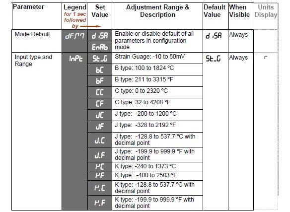
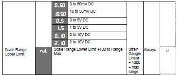
4 Configuration Mode Parameters -4-
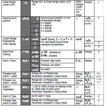
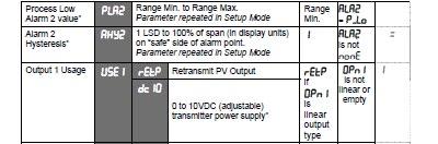
5 -5-
6 -6-

7 *Linear Outputs can be configured to provide an adjustable 0.0 to 10.0VDC transmitter power supply for external devices. 2. Calibration Mode 2.1. Entry to Configuration mode Configuration mode must be completed before adjusting Calibration parameters. First select Calibration mode from Select mode. Hold down and press to force the controller into the Select Mode. The SLCt legend is shown for 1 second, followed by the legend for the current mode. Press or to navigate to the Calibration Mode option, then press. You then need to enter the unlock code using the or keys, then press to enter the mode. Press to scroll through the parameters (while this key is pressed, and for 1 sec after, the parameter legend is shown, then the current value). Press or to change the value. To exit from Calibration mode, hold down and press to return to Select mode. Entry into Calibration Mode is security-protected by the Calibration Mode lock code. Default value is IO. Calibration mode will only be displayed if input type is set to ST_G -7-

8 When the calibration procedure begins ---- appears on the screen. Once Calibration is complete done appears on screen. If there are any Faults with the calibration an error message will appear either Er_r or Er_C. Er_C means the low calibration will fail if the offset is less than -10mV or greater than +10mV. This signifies potential faulty sensors or the high calibration will fail if the count value is less than +20mV or greater than +50mV. This signifies potential faulty sensors Er_r means the high calibration will fail if the mv value is within 10mV of the low calibration value. This is a potential RCAL failure. Setup Mode This mode is normally selected only after Configuration Mode has been completed, or is used when a change to the process set up is required. These parameters must be set as required before attempting to use the indicator in an application. 3 Setup Mode 3.1 Entry into the Setup Mode Setup Mode is entered from Select Mode Hold down and press to force the controller into the Select Mode. The SLCt legend is shown for 1 second, followed by the legend for the current mode. Press or to navigate to the Setup Mode option, then press. Entry into Setup Mode is security-protected by the Setup Mode lock code. Default value is IO. Set LED. This is on in Setup Mode. 3.2 Scrolling through Parameters and Values Press to scroll through the parameters. While this key is pressed, and up to 1 second after, the parameter legend is shown, followed by the current parameter value. -8-

9 3.3 Changing Parameter Values Press to select the required parameter, then press or to set the value as required. Once the displayed value is changed, it is effective is immediately. No confirmation of the change is required. Press to move onto the next parameter. Hold down and press to return to Select Mode. If there is no key activity for two minutes the instrument returns to the operator mode. -9-

10 Alarm parameters marked * are repeated in Configuration Mode. **Once the complete list of Set Up Mode parameters has been displayed, the Operator Mode displays are shown without exiting from Set Up Mode. 4 Operator Mode This is the mode used during normal operation of the instrument. It can be accessed from Select Mode, and is the usual mode entered at power-up. The available displays are dependent upon the setting of the Display Strategy parameter in Configuration Mode. WARNING: IN NORMAL OPERATION, THE OPERATOR MUST NOT REMOVE THE INSTRUMENT FROM ITS HOUSING OR HAVE UNRESTRICTED ACCESS TO THE REAR TERMINALS, AS THIS WOULD PROVIDE POTENTIAL CONTACT WITH HAZARDOUS LIVE PARTS. -10-

11 CAUTION: Set all Configuration Mode parameters and Set Up Mode parameters as required before starting normal operations. 4.1 Entry into Operator Mode This is the normal operating mode of the instrument from power-up. It can also be accessed from any other mode via Select Mode as follows: Hold down and press to force the controller into the Select Mode. The SLCt legend is shown for 1 second, followed by the legend for the current mode. Press or to navigate to the Operator Mode option, then press. 4.2 Scrolling through Parameters and Values Press to scroll through the parameters. While this key is pressed, and up to 1 second after, the parameter legend is shown, followed by the current parameter value. 4.3 Changing Parameter Values Press to select the required parameter, then press or to set the value as required. Once the displayed value is changed, it is effective is immediately. No confirmation of the change is required. Press to move onto the next parameter. The operator can freely view the parameters in this mode, but alteration depends on the Display strategy setting in Configuration Mode. All parameters in Display strategy 6 are read only, and can only be adjusted via Setup mode. -11-
12 1/8 Din Indicator Units Display The /8 Din indicator has an additional Units Display. In Operator Mode, this display shows C or F when a temperature input range is displayed, and is blank for strain gauge or linear inputs. The units display is also used in other modes as a confirmation of the parameter type currently shown in the main display. 5 Alarm Indications The alarm status screen indicates any active alarms, in addition the associated Alarm LED flashes. For latching alarm outputs, the LED FLASHES when the alarm condition exists, and goes to ON when the alarm condition is no longer present if the output has not yet been reset, to indicate that the relay is in the Latched on condition. 5.1 Resetting Latched Alarm Outputs Latched outputs can be reset whilst the Process variable or Alarm Status screens are displayed, via the Digital Input (if fitted), from the front keypad as follows: Press either or to reset the latched relay(s). Outputs will only reset if their alarm condition is no longer present. CAUTION: A reset will affect ALL latched outputs. 5.2 Resetting Alarm 1 Active Time, Minimum PV or Maximum PV The stored Maximum PV value, Minimum PV value or Alarm 1 active Elapsed Time value can be reset via the Digital Input (if fitted), with a communications command via the RS485 module (if fitted) or from the front keypad as follows: Press to select the parameter to be reset. Press either or for three seconds. The display briefly shows ---- when the value is reset before the unit reverts to the requested display. -12-
13 Multi-Point Scaling When Multi-Point Scaling is enabled (MPS = EnAb in Configuration Mode), up to 9 breakpoints can be set to linearize the input signal. This only applies to ma, mv or Voltage input types. For each breakpoint the input scale value (ScAn) is entered in % of input span, followed by the value to be shown (disn) in display units. Each breakpoint s input scale value must be higher than the previous value, but the display values can be either higher or lower. Any scale value set to 100% becomes the last in the series. 6 Tare Feature When Tare is enabled (tare = EnAb in Configuration Mode), it can be used to set the displayed value to zero automatically, by making the PV Offset parameter equal, but opposite to, the current process variable value. Tare can be initiated via the Digital Input (if fitted), or by using the following key press sequence: Press until the process variable is displayed. Hold down and together for three seconds until the display shows YES? Release both keys and press within 3 seconds to confirm the request. The Tare request is aborted if this sequence is not followed exactly. -13-
Model No Universal Input Indicator Start-up Guide
 Model No. 1480 Universal Input Indicator Start-up Guide Contents 1. Setting up a unit straight out of the box... 3 1.1. Entry into Configuration mode... 3 1.2. Scrolling through Parameters and s... 3 1.3.
Operating Manual. Dynisco /8 DIN Indicator Concise Product Manual
 Dynisco 1490 1/8 DIN Indicator Concise Product Manual 59476-9 Operating Manual -1- CAUTION: Installation should be only performed by technically competent personnel. Local Regulations regarding electrical
Instruction Manual. Instrument Amplifier HE 017
 Instruction Manual Instrument Amplifier HE 017 List of contents INSTRUCTION MANUAL: HE 017 Date: 20.4.99 Art.-No.: 320999 S General Safety Instructions.......................................... S 1 General
From lab to production, providing a window into the process. Dynisco's ATC990 and UPR900 Applications and Setup
 From lab to production, providing a window into the process Dynisco's ATC990 and UPR900 Applications and Setup Introduction UPR900 Indicator Is ¼ Din (96x96mm) size, 117mm depth behind the panel. It has
IPM500 Series QuickStart Manual
 IPM500 Series QuickStart Manual The Force of Innovation 10 Thomas Irvine, CA 92618 USA (949) 465-0900 FAX: (949) 465-0905 E-Mail: HTUfutek@futek.comUTH www.futek.com Manufacturer of Load Cells, Pressure
1/32-DIN TEMPERATURE CONTROLLER INSTALLATION, WIRING AND OPERATION MANUAL FORM 3882
 1/32-DIN TEMPERATURE CONTROLLER INSTALLATION, WIRING AND OPERATION MANUAL FORM 3882 This manual is intended for use in support of installation, commissioning and configuration of the 1/32-DIN Temperature
Veeder-Root brand Series S628 Strain Gauge (S628-6XXX)
") Introduction Your Veeder-Root brand S628 Strain Gauge is one model in a family of 1/8 DIN units which offers breakthrough display technology as well as easy-to-program single-line parameters. Designed
Introduction Your Veeder-Root brand S628 Strain Gauge is one model in a family of 1/8 DIN units which offers breakthrough display technology as well as easy-to-program single-line parameters. Designed
-DIN & DIN RaPID TEMPERATURE CONTROLLERS. Product Manual (June 1999)
") 1 -DIN & 1 4 8-DIN RaPID TEMPERATURE CONTROLLERS Product Manual 59131-2 (June 1999) How to use this manual 1 4 -DIN & 1 8 -DIN RaPID TEMPERATURE CONTROLLERS PRODUCT MANUAL VOLUME I OPERATING INSTRUCTIONS
1 -DIN & 1 4 8-DIN RaPID TEMPERATURE CONTROLLERS Product Manual 59131-2 (June 1999) How to use this manual 1 4 -DIN & 1 8 -DIN RaPID TEMPERATURE CONTROLLERS PRODUCT MANUAL VOLUME I OPERATING INSTRUCTIONS
PX Series Balances. Quick Start Guide. Please download the user manual from
 Scan QR Code with your WebCam for downloading the user instruction manual. PX Series Balances Quick Start Guide Please download the user manual from www.ohaus.com. EN-1 1. INSTALLATION 1.1 Select the
Series S628 AC Volts/Amps (S628-3XXX) Veeder-Root brand. Technical Manual
 Veeder-Root brand. Technical Manual") Introduction Your Veeder-Root brand S628 AC Volts/Amps is one model in a family of 1/8 DIN units which offers breakthrough display technology as well as easy-to-program single-line parameters. Designed
Introduction Your Veeder-Root brand S628 AC Volts/Amps is one model in a family of 1/8 DIN units which offers breakthrough display technology as well as easy-to-program single-line parameters. Designed
Truckweigh. operators sheet STGGLOBAL.NET
 Truckweigh operators sheet 1300 998 784 STGGLOBAL.NET FRONT PANEL FUNCTIONALITY The various screens and menus are accessed using the four buttons located around the LCD display, described briefly below.
Omni. User Manual. Economic Self-Tune PID Temperature Controller. Omni 96. Omni 72 72X72. Omni ~ 265 V AC SUPPLY
 Omni Economic Self-Tune PID Temperature Controller Omni 7 Omni 4 6 5 4 3 1 7X7 7 1 11 5 ~ 65 V AC SUPPLY Omni 6 CONTENTS 1. PANEL MOUNTING & ELECTRICAL CONNECTIONS 1. FRONT PANEL : LAYOUT AND OPERATION
7561-PSD Manual Portable Battery Powered Indicator
 7561-PSD Manual Portable Battery Powered Indicator Lebow Products Inc. 1728 Maplelawn Drive P.O. Box 1089 Troy, Michigan 48084-1089 (800) 803-1164 Phone: (248) 643-0220 FAX: (248) 643-0259 Visit our web
DUAL COLOUR DISPLAY DC PROCESS INDICATOR. Product Manual
 1 -DIN 8 DUAL COLOUR DISPLAY DC PROCESS INDICATOR Product Manual 59136-2 HOW TO USE THIS MANUAL This manual comprises two volumes: 1 8-DIN DUAL COLOUR DISPLAY DC PROCESS INDICATOR Product Manual Contents
IPM650 Intelligent Panel-Mount Display
 Quick Start Guide IPM650 Intelligent Panel-Mount Display Sensor Solutions Source Load Torque Pressure Multi Component Calibration Instruments Software www.futek.com Getting Help TECHNICAL SUPPORT For more
5450 NW 33rd Ave, Suite 104 Fort Lauderdale, FL Fruitland Ave Los Angeles, CA UM Channel Monitor.
 5450 NW 33rd Ave, Suite 104 Fort Lauderdale, FL 33309 3211 Fruitland Ave Los Angeles, CA 90058 UM-600 6-Channel Monitor Version 2 Installation and Operation Manual Rev. G P/N145F-12990 PCO 00007462 (c)
DS 96/48 PK. Digital indicator. Manual 42/33-90 EN Rev. 00 DIM
 DS 96/48 PK Digital indicator Manual 42/33-90 EN Rev. 00 A1 A2 DIM E DS 96/48 PK Digital Indicator Manual Document No. 42/33-90 EN Edition 06.01 Revision 00 Manufacturer: ABB Automation Products GmbH Höseler
Analyzer/Sensor to measure UV Spectral Absorbance
 Quick Start-up Guide Integra OUM960/ OUSAF44 Analyzer/Sensor to measure UV Spectral Absorbance This guide is intended to provide quick guidance and help to perform a basic instrument start-up. For detailed
masibus : UT-94 Page 1 of 6 INTRODUCTION SPECIFICATIONS Dimensions Document Ref No. m98a/om/101 Issue No: 08
 INTRODUCTION This is a micro-controller based Universal Transmitter which retransmits the Universal Inputs given, into the required Voltage or current. This instrument provides isolation at 4 levels: (a)
Mercury 11-10PV Pack / Condenser Controller Installation & User Guide V6 or Higher
 PR0334 PR0335 PR0332 PR0333 Mercury 11-10PV Pack / Condenser Controller Installation & User Guide V6 or Higher For Products: - PR0710, PR0711, PR0720, PR0721 Resource Data Management Ltd 80 Johnstone Avenue,
M260 Load Cell Amplifiers
 E L 4 - + 2-3 1-2 M260 Load Cell Amplifiers Description. This fast start guide shows basic installation, setup, and calibration for most applications. For more specific information contact Minsterport.
PROCESS ANALYSERS. SERVOTOUGH FluegasExact Gas Analyser. QuickStart Manual. Part Number: D Revision: 1 Language: UK English
 PROCESS ANALYSERS SERVOTOUGH FluegasExact Gas Analyser QuickStart Manual Part Number: 02700003D Revision: 1 Language: UK English This page intentionally blank TABLE OF CONTENTS 1. INTRODUCTION............................................
6-Channel Monitor. Installation and Operation Manual
 3211 Fruitland Ave Los Angeles, CA 90058 Catalyst Monitor 6-Channel Monitor Version 2 Installation and Operation Manual Rev. H P/N145F-12964 PCO - 00009743 (c) Copyright 2015, Barksdale, Inc. All Rights
Digital Keypad Introduction
 K2 Digital Keypad Introduction The K02 uses the latest microprocessor technology to operate door strikes and security systems that require a momentary (timed) or latching dry contact closure. All programming
LAUREL. Laureate Digital Panel Meter for Load Cell & Microvolt Input ELECTRONICS, INC. Features. Description
 Description LAUREL ELECTRONICS, INC. Features Laureate Digital Panel Meter for Load Cell & Microvolt Input 20, 50, 100, 250 & 500 mv ranges Span adjust from 0 to ±99,999, zero adjust from -99,999 to +99,999
LAUREL. Laureate Digital Panel Meter for Process and Ratiometric Signals ELECTRONICS, INC. Features. Description
 LAUREL ELECTRONICS, INC. Laureate Digital Panel Meter for Process and Ratiometric Signals Features Reads process signals from ±200 mv to ±600V or ±2 ma to ±5A full scale Ratiometric mode for bridges and
Operating Manual. Dynisco ATC990 Graphical 1/4 DIN Process Controller Concise Product Manual
 Dynisco ATC990 Graphical 1/4 DIN Process Controller Concise Product Manual Operating Manual -1- The following symbols are used on the product labels: Caution, refer to installation manual when connecting
MYRIAD QLC 4-CHANNEL MONITOR/CONTROLLER INSTRUCTION MANUAL
 MYRIAD QLC 4-CHANNEL MONITOR/CONTROLLER INSTRUCTION MANUAL VISIT OUR WEBSITE SIGMACONTROLS.COM MYR QLC MANUAL 013114 2 TABLE OF CONTENTS INTRODUCTION 3 Ordering Information Specifications Features WIRING
Instruction Manual. ROYTRONIC EXCEL Series AD9 Programming Guide Electronic Metering Pumps
 Instruction Manual ROYTRONIC EXCEL Series AD9 Programming Guide Electronic Metering Pumps For file reference, please record the following data: Model No: Serial No: Installation Date: Installation Location:
The PM1000 series is a universal 4 digit LED plug-on display for transmitters with 4-20mA 2 wire output and fitted with DIN43650 connector.
 PM1000 SERIES PLUG-ON DISPLAY BRIGHT LED DISPLAY INDICATION RANGE -999 TO +9999 FITS TO DIN 43650 CONNECTOR PLUG-ON TO ANY TRANSMITTER WITH 4-20MA OUTPUT EASY TO SCALE ON SITE ROBUST DESIGN SET POINT OPTION
User Manual Digi-Sense 12-Channel Benchtop Data Logging Thermocouple Thermometer
 User Manual Digi-Sense 12-Channel Benchtop Data Logging Thermocouple Thermometer Model: 92000-01 THE STANDARD IN PRECISION MEASUREMENT Table of Contents Introduction... 3 Unpacking... 3 Initial Setup...3
AS Keypad User Manual
 AS Keypad User Manual Specifications Operating Voltage: 12~24 VAC/DC Current Draw: TBA Input: request-to-exit (for Relay 1) time out reed switch contact (for Relay 1) Output: Relay 1: N.O./N.C./Com. Output
PROCESS ANALYSERS. SERVOTOUGH OxyExact (2200) Operator Manual. Part Number: 02210/001A Revision: 4 Language: UK English
 Operator Manual. Part Number: 02210/001A Revision: 4 Language: UK English") PROCESS ANALYSERS SERVOTOUGH OxyExact (2200) Operator Manual Part Number: 02210/001A Revision: 4 Language: UK English This page intentionally blank xendos 2200 Operator Manual Ref: 02210/001A/4 Order as
PROCESS ANALYSERS SERVOTOUGH OxyExact (2200) Operator Manual Part Number: 02210/001A Revision: 4 Language: UK English This page intentionally blank xendos 2200 Operator Manual Ref: 02210/001A/4 Order as
Trident and Trident X2 Digital Process and Temperature Panel Meter
 Sign In New User ISO 9001:2008 Certified Quality System Home Products Online Tools Videos Downloads About Us Store Contact Policies Trident and Trident X2 Digital Process and Temperature Panel Meter Products
Security System User Guide
 Security System User Guide Setting the System: 1. Go to the keypad and key in your access code. (Alternatively, if you have a proximity tag, present your tag to the keypad.) Either - Full Set: 2. Press
LAUREL ELECTRONICS, INC.
 LAUREL ELECTRONICS, INC. Laureate RTD Temperature Panel Meter / Controller Features Factory calibrated for 100Ω platinum, 10Ω copper & 120Ω nickel RTDs 2, 3 or 4-wire connection with lead resistance compensation
T80 Universal Transmitter S80 Intelligent Sensors
 T80 Universal Transmitter S80 Intelligent Sensors Presented by: January 2012 ELECTRO-CHEMICAL DEVICES T80 Universal Transmitter One Transmitter for Multiple Measurements ph ORP Dissolved Oxygen All Specific
Contents. Temperature & Process Measurement Indicators Setup Guide
 Contents Introduction... 2 Installation... 3 Connections... 5 Connecting the Sensor... 6 Powering the Instrument... 7 Operator Functions... 8 The Setup Menus... 9 Configuration Menu Map... 12 Menu Options...
Model SC500. Programmable Single-Channel Transducer Indicator/Conditioner DESCRIPTION FEATURES
 Programmable Single-Channel Transducer Indicator/Conditioner DESCRIPTION The SC series models are self-calibrating microprocessorbased transducer signal conditioners when used with sig mod equipped transducers.
Using a Memory Card. Chapter 4. Chapter Objectives. Supported Memory Cards
 Chapter Objectives This chapter describes: supported memory cards. using the memory card retainer. loading application from a memory card. loading application on a memory card. storing font files on a
Instruction Manual July sitrans RD200
 Instruction Manual July 2007 sitrans RD200 Safety Guidelines: Warning notices must be observed to ensure personal safety as well as that of others, and to protect the product and the connected equipment.
SINGLE-CHANNEL PROCESS CONTROLLERS & TEMP. DISPLAYS D3820/D3830 Series
 The Digitec Series D3800 Panel Meters offer many features and performance capabilities to suit a wide range of industrial applications. The D3820 and D3830 are available in the ranges of 4-20mA, 0-10 VDC,
SERIES C 1ZC 16C 18C 19C 25C
 SERIES C 1ZC 16C 18C 19C 25C TEMPERATURE / PROCESS CONTROLLER Controller Operator Manual Athena is a registered trademark and Multi-Comm is a trademark of Athena Controls, Inc. Platinel is a trademark
TRACKER 240 SERIES. Load Cell and Weighing Indicators. A Precision Measurement Instrument with Outstanding Features
 TRACKER 240 SERIES Load Cell and Weighing Indicators A Precision Measurement Instrument with Outstanding Features TRACKER 240 SERIES INDICATORS Ratiometric Measurement Tare and Auto Transducer Excitation
Multi Units Humidity/Temperature Transmitter. HygroViewer Model JW300 User Manual
 Multi Units Humidity/Temperature Transmitter HygroViewer Model JW300 User Manual 1. Electrical Wired & Installation The power cord is a one-meter length, 22 AWG, 7 different colors for recognition. Please
MICRO SERIES PROCESS DISPLAYS LARGE DIGIT MODELS
 The MICRO SERIES PROCESS DISPLAYS LARGE DIGIT MODELS Mighty-5 DPM MODELS Micro-P & Mighty-1 Mighty-1 Micro-P ELECTRO-NUMERICS, INC. Introduction The Electro-Numerics family of Digital Panel Meters and
5450 NW 33rd Ave, Suite 104 Fort Lauderdale, FL Fruitland Ave Los Angeles, CA SST7000 SST7100. Speed Switch / Transmitter
 5450 NW 33rd Ave, Suite 104 Fort Lauderdale, FL 33309 3211 Fruitland Ave Los Angeles, CA 90058 SST7000 SST7100 Speed Switch / Transmitter Installation and Operation Manual Rev. C P/N145F-13112 PCO 00009270
10 Thomas, Irvine, CA USA Tel: (949) Fax: (949) IPM650 Product Manual
 Fax: (949) IPM650 Product Manual") IPM650 Product Manual Table of Contents 1 Receiving & Unpacking...- 5-1.1 Unpacking...- 5-1.2 Storage...- 5-1.3 Accessories Supplied...- 5-2 Safety Considerations & Care for Your Device...- 5-3 Important
IPM650 Product Manual Table of Contents 1 Receiving & Unpacking...- 5-1.1 Unpacking...- 5-1.2 Storage...- 5-1.3 Accessories Supplied...- 5-2 Safety Considerations & Care for Your Device...- 5-3 Important
Omni + User Manual. Dual Setpoint Temperature Controller with Programmable Input & TIMER. Omni 96+ Omni 72+ Omni 48+ TMR TMR TMR
 Omni + Dual Setpoint Temperature Controller with Programmable Input & TIMER Omni 72+ Omni 48+ TMR TMR Omni 96+ TMR CONTENTS 1. PANEL MOUNTING & ELECTRICAL CONNECTIONS 1 2. FRONT PANEL : LAYOUT AND OPERATION
D45 System. Digital colour entrance panel with addresses list
 D45 System Digital colour entrance panel Description Front view D45 System entrance panel with colour camera and backlighted alphanumeric keyboard equipped with pushbutton to direct calls to the porter
FG-3000R Digital Force Gauge Operation Manual
 FG-3000R Digital Force Gauge Operation Manual Operators should wear protection such as a mask and gloves in case pieces or components break away from the unit under test. Whether the unit is ON or OFF,
TC Type Range Conformity Error. J -210 C to +760 C (-347 F to F) ±0.09 C (±0.16 F) K -244 C to C (-408 F to F) ±0.1 C (±0.
 ±0.09 C (±0.16 F) K -244 C to C (-408 F to F) ±0.1 C (±0.") LAUREL ELECTRONICS, INC. Laureate Thermocouple Panel Meter / Controller Features Factory calibrated for thermocouple types J, K, T, E, N, R, S Entire range of each thermocouple in one scale Highly accurate
LAUREL ELECTRONICS, INC. Laureate Thermocouple Panel Meter / Controller Features Factory calibrated for thermocouple types J, K, T, E, N, R, S Entire range of each thermocouple in one scale Highly accurate
Model M3LLC STRAIN GAUGE TRANSMITTER. PC CONFIGURATOR SOFTWARE Model: M3LLCCFG. Users Manual M3LLCCFG USERS MANUAL EM-9197-T
 Model M3LLC STRAIN GAUGE TRANSMITTER PC CONFIGURATOR SOFTWARE Model: M3LLCCFG Users Manual 1 CONTENTS 1. GETTING STARTED...3 1.1 PC REQUIREMENTS...3 1.2 INSTALLING & DELETING THE PROGRAM...3 1.3 STARTING
CII: Current Input, Isolated
 Safety 1. Application CII Driver Card 2. Installation 2.1 Services 2.2 Driver Card Installation 2.3 Driver Wiring 3. Configuration - Operation 3.1 Diagnostics 3.2 Calibration 4. Specifications Safety Electrical
Model T28 Transmitter
 Model T28 Transmitter Product Training Presented by: Joe Bradley October 2009 ELECTRO-CHEMICAL DEVICES Model T28 Transmitter Two Wire Transmitter Loop Powered 24 VDC @ 500 Ω Measurement Choices ph ORP
FG-3000 Digital Force Gauge Operation Manual
 FG-3000 Digital Force Gauge Operation Manual Operators should wear protection such as a mask and gloves in case pieces or components break away from the unit under test. Whether the unit is ON or OFF,
AUTOMATION. Operator s Manual PG-7. Full Access. Doc Part Rev B, 07/18. Automation Products Group, Inc.
 AUTOMATION P R O D U C T S GROUP, INC. Operator s Manual PG-7 Full Access Doc. 9003312 Part 200180 Rev B, 07/18 Tel: 1/888/525-7300 Fax: 1/435/753-7490 www.apgsensors.com E-mail: sales@apgsensors.com PG7
Calibration & Connectivity
 Calibration & Connectivity TS-700 Series Digital Indicators This document supplements the User s Guide TS-700 MS TS-700 SS TS-700 WB Full Function/Advanced Function Digital Indicator www.trinerscale.com
Installing Keypad and Backplate
 Installing Keypad and Backplate Fig.1 Positioning of Fixing Holes and Cable Outlet Cable Outlet, Drill Diameter 10mm for Cable Access Remove the back plate, which is fitted to rear of the keypad, using
Intrinsically Safe Temperature Concentrator System
 Intrinsically Safe Temperature Concentrator System Up to 32 Channels per Network HART and PC configurable 2, 3 & 4-wire RTD or Thermocouple Transmitter like Sensor Diagnostics and performance, RTD ±0.1
Operating Instructions tico 735 AC Volts/Amps Indicator
 Operating Instructions tico 735 AC Volts/Amps Indicator Introduction Your Hengstler tico 735 for AC Volts and Amps is one model in a family of 1/8 DIN units which offers breakthrough display technology
Elevation Window Control System
 Elevation Window Control System Keypad installation and user guide August 2013 copyright by ASSA ABLOY WARNINGS Read these instructions prior to the activation of the keypad. Save this user guide in a
1. Installation. 2. Configuration - Operation. 3. Specifications. Safety
 Safety 1. Installation 1.1 OP_ext: Services 1.2 Driver Card Installation 1.3 Sensor Types 1.4 Sensor Wiring 1.5 Controller Wiring 2. Configuration - Operation 2.1 Replaces ph Sensor 2.2 AS -Flex Series
USER INSTRUCTION MANUAL FOR LOADCELL TRANSMITTER MODEL TDC/I/0550 (SOFTWARE: VER2A) INDEX
 INDEX") USER INSTRUCTION MANUAL FOR LOADCELL TRANSMITTER MODEL TDC/I/0550 (SOFTWARE: VER2A) INDEX DOCUMENT NO: TDC 0550 MANUAL - 2 1.0) INTRODUCTION. PAGE 2 1.1) ABOUT THIS MANUAL. PAGE 2 1.2) INTRODUCTION. PAGE
USER INSTRUCTION MANUAL FOR LOADCELL TRANSMITTER MODEL TDC/I/0550 (SOFTWARE: VER2A) INDEX DOCUMENT NO: TDC 0550 MANUAL - 2 1.0) INTRODUCTION. PAGE 2 1.1) ABOUT THIS MANUAL. PAGE 2 1.2) INTRODUCTION. PAGE
LAUREL. Laureate RTD Temperature Panel Meter / Controller ELECTRONICS, INC. Features. Description. Specifications
 LAUREL ELECTRONICS, INC. Laureate RTD Temperature Panel Meter / Controller Features Factory calibrated for 100Ω platinum, 10Ω copper & 120Ω nickel RTDs 2, 3 or 4-wire connection with lead resistance compensation
Introduction. Features. Index
 Introduction A new standard of performance and functionality in a compact preset counter. The V454501 Single Preset Counter offers a pre-settable counter with full calibration for a variety of applications.
Digital Bench Scale. Revision 8.93 August 12, 1993
 Digital Bench Scale Revision 8.93 August 12, 1993 Salter Brecknell Weighing Products 1000 Armstrong Drive Fairmont, MN 56031 Tel (800) 637-0529 Tel (507) 238-8702 Fax (507) 238-8271 E-mail: sales@salterbrecknell.com
DUAL COLOUR DISPLAY TEMPERATURE INDICATOR. Product Manual
 1 -DIN 8 DUAL COLOUR DISPLAY TEMPERATURE INDICATOR Product Manual -2 HOW TO USE THIS MANUAL This manual comprises two volumes: 1 8-DIN DUAL COLOUR DISPLAY TEMPERATURE INDICATOR Product Manual Contents
Installation and User Manual
 S2 Metal Waterproof Access Control Unit Installation and User Manual (Ness Part No. 101-082) 1 Introduction Ness S2 is an advanced, waterproof (IP65 rated) proximity and PIN Access Controller. S2 can support
RITZ / Turbine controls DISPLAY
 RITZ / Turbine controls DISPLAY CANCEL EXIT OK MENU F1 F2 F3 F4 The control/display unit has a CPU, an LCD display and 8 keys. 2 LEDs also display particular operational conditions (e.g. plant ON, faults,
SHIMPO INSTRUMENTS DIGITAL PANEL METER OWNERS MANUAL
 SHIMPO INSTRUMENTS DIGITAL PANEL METER OWNERS MANUAL SHIMPO INSTRUMENTS 1701 Glenlake Avenue, Itasca, Illinois 60143, USA Phone: (800) 237-7079 Fax: (630) 924-0342 www.shimpoinst.com 1. ORDERING GUIDE
TRACKER 220 SERIES. Digital Panel Indicators. A Complete Range of Universal Input Digital Panel Indicators for Temperature and Process Measurement
 TRACKER 220 SERIES Digital Panel Indicators A Complete Range of Universal Input Digital Panel Indicators for Temperature and Process Measurement TRACKER 220 SERIES INDICATORS Universal Input Analogue Output
SERIES CMT CARBON MONOXIDE GAS TRANSMITTER
 SERIES CMT CARBON MONOXIDE GAS TRANSMITTER INSTALLATION OPERATION AND MAINTENANCE MANUAL DWYER INTRUMENTS, INC. PO BOX 373, MICHIGAN CITY, IN. 46360 USA PHONE: 800-872-9141 FAX: 219-872-9057 Web: www.dwyer-inst.com
The Tracker 220 Series A Complete Range of Universal Input Digital Panel Indicators for Temperature and Process Measurement
 Acquisition Measurement Control The Tracker 220 Series A Complete Range of Universal Input Digital Panel Indicators for Temperature and Process Measurement TRACKER 220 SERIES INDICATORS Universal Input
HL100 Controller Operator's Manual
 2230051/1 IM-S27-11 CH Issue 1 HL100 Controller Operator's Manual Volume 1 Operating instructions 1 Operator mode 2 Set up mode 3 RS485 serial communications Volume 2 Installation and configuration instructions
Master-Touch INSTRUCTION MANUAL. Series 9000MP Multipoint System Series 9600MP System Control Panel Thermal Gas Mass Flowmeters. version 7.
 Master-Touch version 7.x firmware Series 9000MP Multipoint System Series 9600MP System Control Panel Thermal Gas Mass Flowmeters INSTRUCTION MANUAL 80201501 Addendum Rev. C www.epiflow.com Eldridge Products,
12-36 VDC/12-24 VAC Power Option 4-Digit Display, 0.56 (14.2 mm) or 1.20 (30.5 mm)
 or 1.20 (30.5 mm)") 4-20 ma & Relay Output Features 4-20 ma, ± 10 V, TC & RTD Inputs 12-36 VDC/12-24 VAC Power Option 4-Digit Display, 0.56 (14.2 mm) or 1.20 (30.5 mm) 24 VDC @ 200 ma Transmitter Power Supply Options Type
4-20 ma & Relay Output Features 4-20 ma, ± 10 V, TC & RTD Inputs 12-36 VDC/12-24 VAC Power Option 4-Digit Display, 0.56 (14.2 mm) or 1.20 (30.5 mm) 24 VDC @ 200 ma Transmitter Power Supply Options Type
HANDHELD CALIBRATOR-MULTIMETER OC502-t
 OC502-t_GBM_21311 HANDHELD CALIBRATOR-MULTIMETER OC502-t Owner s Manual ORBIT CONTROLS AG Zürcherstrasse 137 CH-8952 Schlieren/ZH Tel: + 41 44 730 2753 Fax: + 41 44 730 2783 info@orbitcontrols.ch www.orbitcontrols.ch
Trident & Trident X2 PD765
 Trident & Trident X2 PD765 Quick Start Guide Thank you for purchasing the Trident PD765 process meter! This quick start guide will briefly describe some of the common setup procedures for this meter. This
GS100P. Weighing Controller. Contents. Order Codes
 GS100P Weighing Controller 1 This intelligent weighing controller comes precalibrated to suit either a 4-wire or a 6-wire strain gauge input, and has a number of advanced functions designed specifically
- SELF-TUNING PID ALGORITHM - INTUITIVE COLOR DISPLAY WITH TEXT MESSAGING - UNIVERSAL PROCESS AND TC/RTD INPUTS - MULTI- FUNCTION RAMP- DWELL/PROCESS
 ELK. ETK COMPACT BASIC CONTROL - SELF-TUNING PID ALGORITHM - INTUITIVE COLOR DISPLAY WITH TEXT MESSAGING - UNIVERSAL PROCESS AND TC/RTD INPUTS - MULTI- FUNCTION RAMP- DWELL/PROCESS TIMER - SOFT START OUTPUT
PD765 TRIDENT. Trident Series Process & Temperature Meters.
 PD765 Trident Series Process & Temperature Meters TRIDENT PROCESS & Temp 4-20 ma, ± 10 V, TC & RTD Inputs 4-Digit Display, 0.56 (14.2 mm) or 1.20 (30.5 mm) Type 4X, NEMA 4X, IP65 Front 1/8 DIN Shallow
M A C 3 Wind Speed Alarm & Controller
 M A C 3 Wind Speed Alarm & Controller Installation Instructions Thank you for purchasing the MAC3 wind speed alarm and controller. This manual is designed to lead you through a step-by-step process to
Quick Start Guide. Cyl-Tel & Tank-Tel Liquid Level Gauges. Designed and Built by: Chart Inc th Street NW New Prague, MN USA (800)
") Quick Start Guide Cyl-Tel & Tank-Tel Liquid Level Gauges Designed and Built by: Chart Inc. 407 7th Street NW New Prague, MN 56071 USA (800) 400-4683 Part Number 20664277 Rev. D 2015 Chart Inc. Quick Start
Quick Start Guide Cyl-Tel & Tank-Tel Liquid Level Gauges Designed and Built by: Chart Inc. 407 7th Street NW New Prague, MN 56071 USA (800) 400-4683 Part Number 20664277 Rev. D 2015 Chart Inc. Quick Start
3690 N.W. 53rd Street Fort Lauderdale, FL SC-2124 SC-2124M. 24 Channel Universal Scanner. Installation and Operation Manual P/N 145F-11902
 3690 N.W. 53rd Street Fort Lauderdale, FL 33309 SC-2124 SC-2124M 24 Channel Universal Scanner Installation and Operation Manual P/N 145F-11902 Rev. 3.30 (c) Copyright 2000, Dynalco Controls All Rights
Communications and Displays. SITRANS RD300 - Dual-Input Process Meter Operating Instructions 02/2014
 Communications and Displays SITRANS RD300 - Dual-Input Process Meter Operating Instructions 02/2014 Safety Guidelines: Warning notices must be observed to ensure personal safety as well as that of others,
OLS VT10 SERIES STANDARD DUAL DISPLAY PID AUTOTUNE RAMP-TO-SETPOINT ULC, UL, CE (4810) AUTO / MANUAL 15 SECURITY OPTIONS UNIVERSAL INPUT
 AUTO / MANUAL 15 SECURITY OPTIONS UNIVERSAL INPUT") TEMPERATURE TURE CONTROLS OLS VT10 SERIES pg.1 STANDARD DUAL DISPLAY PID AUTOTUNE RAMP-TO-SETPOINT ULC, UL, CE (4810) AUTO / MANUAL 15 SECURITY OPTIONS UNIVERSAL INPUT OPTIONS DUAL OUTPUT ALARMS - 15 TYPES
TEMPERATURE TURE CONTROLS OLS VT10 SERIES pg.1 STANDARD DUAL DISPLAY PID AUTOTUNE RAMP-TO-SETPOINT ULC, UL, CE (4810) AUTO / MANUAL 15 SECURITY OPTIONS UNIVERSAL INPUT OPTIONS DUAL OUTPUT ALARMS - 15 TYPES
MTII4200 Level Transmitter Installation, Operation & Maintenance Instructions
 Specialists in Liquid Level Indication MTII4200 Level Transmitter Installation, Operation & Maintenance Instructions Section: M500 Bulletin: M500.31 Date: 05-17-16 Supersedes: 09-30-11 1. INTRODUCTION
+GF+ SIGNET ph/orp Transmitter Instructions
 GF SIGNET 8750 ph/orp Transmitter Instructions ENGLISH 8750.090 A9/99 English CAUTION! Remove power to unit before wiring input and output connections. Follow instructions carefully to avoid personal injury.
Operation Manual TX10 1/8 DIN Microcomputer Based ph/orp Controller
 Operation Manual TX10 1/8 DIN Microcomputer Based /ORP Controller 11751 Markon Drive Garden Grove, CA. 92841 U.S.A. pg. 1 CONTENTS GENERAL INTRODUCTION.....3 INITIAL INSPECTION......3 USING THE Sensorex
PD765 TRIDENT. Trident Series Process & Temperature Meters.
 PD765 Trident Series Process & Temperature Meters TRIDENT PROCESS & Temp 4-20 ma, ± 10 V, TC & RTD Inputs 4-Digit Display, 0.56" (14.2 mm) or 1.20" (30.5 mm) Linear or Square Root with Low-Flow Cutoff
User Manual M1. Thermocouple type K, B, S, N, E, T, R, L, J. Technical features:
 User Manual M1 Thermocouple type K, B, S, N, E, T, R, L, J Technical features: red display of -1999 9999 digits (optional: green, orange or blue display) minimal installation depth: 97 mm without plug-in
UDC 1000 and UDC 1500 MICRO-PRO SERIES UNIVERSAL DIGITAL CONTROLLERS
 UDC 1000 and UDC 1500 MICRO-PRO SERIES UNIVERSAL DIGITAL CONTROLLERS EN0I-6041 12/99 PRODUCT SPECIFICATION SHEET OVERVIEW The UDC 1000 and UDC 1500 are microprocessor-based 1/16 DIN and 1/8 DIN controllers
QUICKSTART GUIDE. Infrared Gas Analyzer. Teledyne Analytical Instruments
 QUICKSTART GUIDE MODEL 7500 Teledyne Analytical Instruments Quickstart Guide Teledyne Analytical Instruments Model 7500 Quickstart Guide GETTING STARTED This Quickstart Guide is designed to get you set
Brooks Service Tool TM for QUANTIM Precision Mass Measurement and Control
 Installation and Operation Manual Precision Mass Measurement and Control www.brooksinstrument.com Installation and Operation Manual Essential Instructions Read this page before proceeding! Brooks Instrument
Displays Transducers. Displays and transducers
 JJ Displays JJ Transducers Displays and transducers DS_Displays_and_transducers 06/2016 225 Displays and transducers Our electronic devices for flow and volume measurement are suitable for all SIKA flow
Iso DIN. User Manual. 1 channel Earth Fault Monitoring
 Page 1 of 5 2017 03 20 User Manual Iso DIN Iso DIN User Manual 1 channel Earth Fault Monitoring Megacon AB Ranhammarsvägen 20 S 168 67 Bromma Sweden Tel: 08 402 42 50 sales@megacon.se www.megacon.se eee
installation quick guide integrated access control & environmental monitoring
 installation quick guide integrated access control & environmental monitoring Introduction This Installation Quick Guide is suitable for standard wallmountable AX300 controllers. Illustrative technical
TRASK SERIES 2 DIGITAL PANEL METER OWNERS MANUAL
 TRASK SERIES 2 DIGITAL PANEL METER OWNERS MANUAL Now with Ethernet Trask Instrumentation Inc. 414 West Poinsett Street, Greer, SC 29650 Tel: (864) 848-3993 Fax: (864) 848-9569 mike@traskinst.com See us
Operating Instructions VEGAMET 381
 Operating Instructions VEGAMET 381 in out Contents Contents 1 About this document... 4 1.1 Function... 4 1.2 Target group... 4 1.3 Symbolism used... 4 2 For your safety... 6 2.1 Authorised personnel...