INSTALLATION & USER MANUAL
|
|
|
- Kerrie Armstrong
- 6 years ago
- Views:
Transcription


1 INSTALLATION & USER MANUAL MODELS EVMS & GSVMS with Rain Sensor Fax: Eastern Facility: Spencer Drive, Unit A, Wells, ME 000 Western Facility: Echo Avenue, Reno, NV 0
2 TABLE OF CONTENTS Features Features In The In Box The Box Basic Further Operation Items Required Basic Operation Solar Panel and Rain Sensor Installation Solar Panel and Operator Installation Remote Setup and Configuration Operator Installation Pairing Remote Solar Panel to Operator and Rain Sensor Installation Multiple Wiring Remotes the Solar Panel and Rain Sensor to the Operator Secondary Remote Remote Setup Configuration and Configuration Pairing Remote to Operator 0 Rain Sensor Operation Multiple Remotes Time to Close Operation Secondary Remote Configuration Setting Rain MAX-OPEN Sensor Operation Limit Setting Time Temperature to Close Operation Control (TC) Checking Setting STATUS MAX-OPEN of Batteries Limit and Charging Current Setting Temperature Control (TC) Re-Zoning Checking STATUS of Batteries and Charging Current Remote Display Re-Zoning Troubleshooting Remote Display Tips Troubleshooting Tips FEATURES Operator Highlights:. Powered by a solar charged NiMH battery pack.. End-user replaceable battery pack.. Operating force rating of 0 lbs at the chain.. Maximum opener chain travel of inches with option to program various lengths.. Bright White cover standard. Paintable surface for custom color match.. Attachment link on chain is fastened to the sash by a release pin.. AC trickle charger included.. Adaptable to awning and hopper windows, and skylights. Remote Highlights:. Large and readable display with bi-directional feedback from the operator: a. Open / Close status percentage displayed. b. Operator and remote battery level percentage displayed. c. Solar charge rate displayed in ma. d. Temperature display.. programmable zones with up to operators assigned per zone. Able to control up to operators.. Automatic temperature control function.. Multiple remotes can be used on a Main / Secondary relationship. Pairing and settings can be sent from a main remote to secondary remotes wirelessly.. Stand-up base with wall mount option.. Remote uses standard () AA batteries.
3 SOLAR SMART REMOTE SOLAR SMART OPERATOR Lifting Chain Chain Clip Battery Cover Operator Battery Connector Mounting Bracket AC Trickle Charger
4 BASIC OPERATION Using the operator requires that it has been paired to the remote. Refer to Initial Remote Setup and Configuration. Opening and Closing of an Operator. Press any key to wake up the remote, if the LCD display has powered off.. Press ZONE to choose a single zone ( thru ) of operators or ALL to operate all operators in all zones.. Press OPEN or CLOSE to open or close the window/skylight.. Press OPEN or CLOSE during operation to STOP the operator at any time. Enable / Disable Automatic Functions. Press and hold AUTO to show or remove AUTO from the display, thus enabling or disabling the temperature control (TC) or Time-to-Close (P) functions.
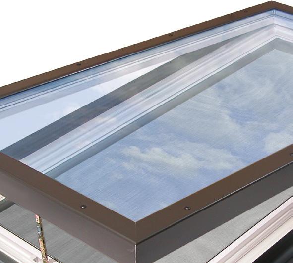
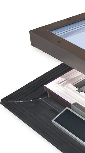
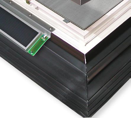
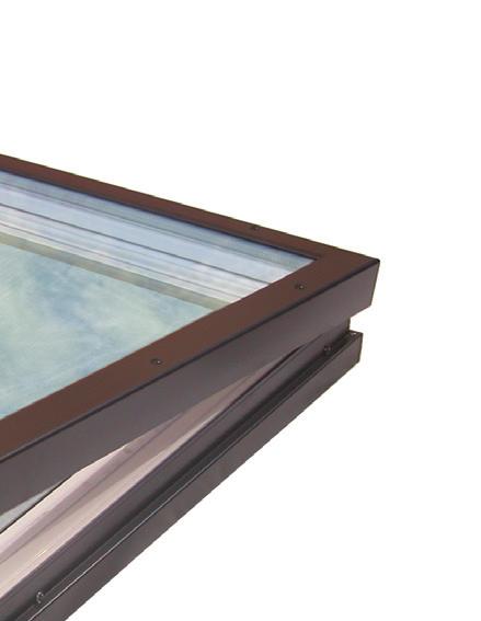
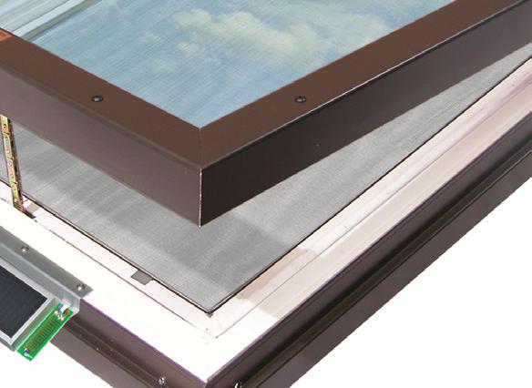
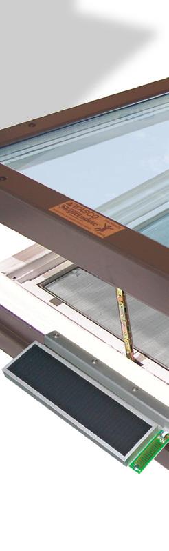
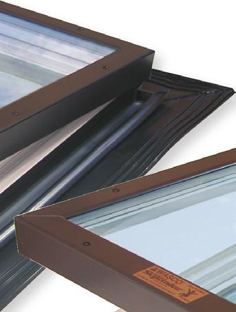
5 INSTALLATION of the SOLAR PANEL and RAIN SENSOR NOTE: The skylight needs to be installed on the roof before attaching the solar panel.. Review the separate instructions for motor operation and open the skylight fully with the remote control.. Connect the solar panel to the wire on the exterior of the skylight at the low side. The connector can only go together one way and will click when locked together.. Locate the solar panel on the skylight frame as shown below, centered side to side. Install the panel with the screws supplied.. Close the skylight to complete the installation.
6 INITIAL REMOTE SETUP and CONFIGURATION NOTE: The remote has been configured and paired by Wasco. Keep instructions for future use. The following are applicable for configuring the main remote only. To configure additional remotes, refer to 'Multiple Remotes' for more information. Pressing MODE does not work when zone in remote display is set to ALL. Press ZONE to exit zone ALL. All steps must be performed within 0 seconds or the remote control will default to the previous settings.. Open the remote battery cover and install the two AA alkaline batteries and replace the cover.. All the screen display segments will be visible while the remote runs a self-test which lasts for a few seconds. After which, SET will be displayed.. Press to choose either C (Celsius) or F (Fahrenheit).. Press ENTER to save your selection.. Press to choose either M (main) or S (secondary). Select M for main. Note: Secondary is only used when using additional remotes. Refer to 'Multiple Remotes' for more information.. Press ENTER to save your selection.. ZONE ALL and the temperature should now be displayed.
7 PAIRING the REMOTE to the OPERATOR Pairing sets up communication between the remote and the operator. The remote will be able to control all operators assigned within a single zone simultaneously, or control all zones at once. There are zones ( thru ), with each zone containing ID numbers ( thru ). Each operator will need to be assigned to a zone and ID number. Each zone and ID number combination can only be assigned one operator. The following instructions are applicable to pairing the first and additional operators to a single remote. Each operator can only be paired with one main remote, however multiple secondary remotes may be used once setup and configured. The Operator The remote will need to be paired within minutes, or the operator will default back to the previous settings.. Remove the battery cover from the operator. If connected, disconnect the battery connector from the operator circuit board, for at least 0 seconds. NOTE: The Solar Panel must also be disconnected at this time.. Connect the battery connector to the operator circuit board, pressing firmly until the plug is locked into place.. The red light on the circuit board will continually blink while it is in pairing mode. The Remote. Press any key to wake up the remote, if the display has powered off.. Press and hold the MODE, release when PAIR SET is displayed.. Press ZONE as necessary to choose the appropriate zone ( thru ).. Press ENTER to save your selection.. Press to choose the ID number ( thru ) within the zone. ID numbers already in use will not be displayed.. Press ENTER to save your selection. The remote will attempt to pair to the operator. (continues on next page)
8 . SUCC will be displayed to indicate a successful pairing. The operator will then fully open then close one cycle. DO NOT press any buttons on the remote until this cycle completes. a. If a FAIL message is displayed, press ENTER on the remote to try to pair again. b. If a FAIL message is displayed again, ensure that the operator is in pairing mode. If the red light is not still blinking, disconnect and reconnect the battery connector on the operator and repeat steps - again. MULTIPLE REMOTES It is intended that one or multiple operators may be controlled from multiple secondary remotes. This is done by sending the pairing and settings stored in the first configured M (main) remote, to the additional S (secondary) remote(s). Secondary remotes will be 'copies' of the main. Any changes to operator zones, ID numbers, and/or adding additional operators can only be performed using the main remote. The changed settings would then need to be re-sent from the main to the secondary remote(s). Ensure that a main remote has been configured as outlined in 'Remote Setup and Configuration' and that it has been paired to the operator(s) as described in 'Paring Remote to Operator.' Secondary Remote Configuration All steps must be performed within 0 seconds or the remote control will default to the previous settings.. Open the remote battery cover; remove and reinstall two AA alkaline batteries and replace the cover.. All the screen display segments will be visible while the remote runs a self-test which lasts for a few seconds. After which, SET will be shown on the Display to indicate input is required.. Press to choose either C (Celsius) or F (Fahrenheit).. Press ENTER to save your selection.. Press to choose either M (main) or S (secondary). Select S for secondary.. Press ENTER to save your selection.. ZONE ALL and the temperature should now be displayed.
9 . SECONDARY REMOTE STEPS a. Press and hold MODE, release when PAIR SET is displayed and the S in the upper-right corner is flashing. b. Press ENTER. The secondary remote will now be waiting to receive the transmission from the main remote. It will wait for 0 seconds.. MAIN REMOTE STEPS a. Press and hold MODE, release when PAIR SET is displayed. b. Press MODE twice to move past RE-ZONE to display M in the upper-right corner as flashing. c. Press ENTER to begin transmitting the settings to the secondary remote. d. SUCC will be displayed on a successful transfer of settings. i. If a FAIL message is displayed instead, be sure that the secondary remote is still configured to be waiting to receive the transmission. Press ENTER to retry.
10 RAIN SENSOR The rain sensor should be installed horizontally, with a slight tilt to prevent water from pooling. The sensor location depends on many factors. The key to proper installation is that the sensor must be level and exposed when the operator opens the unit. The wires from the sensor to the operator must be ran to the operator in a water proof manner so as to not induce water penetration that could damage the interior. The sensor is not polarity sensitive so it does not matter which wire goes to which connector in the operator. By default, the rain sensor is enabled when the remote is initially paired to the operator regardless of whether the rain sensor is attached or not. When the rain sensor is enabled a small umbrella will be displayed in the top right hand display box.. To enable or disable the rain sensor, press any key to wake up the remote if the LCD display has powered off.. Press MODE.. Press ZONE as necessary to choose the desired zone.. After the desired zone is flashing, press ENTER.. MAX-OPEN will know be flashing.. Press until the icon is displayed and flashing, press ENTER.. Press to choose the ID number ( thru ) within the zone.. Press ENTER to confirm your selection.. Press to choose between ON and OFF while they are flashing. 0. Press ENTER to save your setting.. LCD displays steady ON or OFF for one second, then SUCC for seconds, indicating success. Press MODE a few times to return to the home screen a. If setting not successful, LCD displays FAIL for second, then returns to the same step # to retry setting. RAIN SENSOR OPERATION When a drop of water is on the sensor the operator may not react immediately. The control system actually takes multiple reading in an effort to avoid false readings and possible cycling of the operator before it sends the close or open commands. If the operator is manually opened when the rain sensor is enabled AND there is water present on the sensor, the operator will close and the umbrella icon will blink on the Remote. If you desire to open the operator at this time, the sensor will need to be disabled before it will stay in the open position. If the Rain Sensor and the Automated Temperature Control are enabled at the same time, the Rain Sensor will take precedence over the Temperature Control. In other words, if rain is detected, the operator will close regardless of the temperature until such time as water is no longer detected on the sensor before it will automatically re-open. As noted above, the rain sensor is designed to detect a lowering of the resistance between the metallic strips on the sensor. The resistance can be lowered by a number of factors including moss, sap, heavy dew, or condensation drops from surrounding structures. Therefore it is important to periodically clean the sensor to maintain proper operation. If all operations function properly except when the Rain Sensor is enabled, cleaning the Rain Sensor is recommended. 0
11 TIME TO CLOSE The Time to Close (P) function will automatically close the operator after a user defined time period. The user selected time period is in 0 minute increments from 0 to hour. From to hours, the increments change to 0 minutes.. Press any key to wake up remote, if the LCD display has powered off.. Press MODE - the LCD should display SET, and ZONE should be flashing.. Press ZONE as necessary to choose the appropriate zone (-).. When the correct zone is flashing, press ENTER. MAX-OPEN will be displayed and flashing.. Press until P is displayed and flashing.. Press ENTER.. Press until the desired Time To Close is displayed and flashing or NULL to turn function off.. Press ENTER. 0. ST is now displayed and flashing. Press MODE to return to the home screen OR press to scroll and set other features.. The Time To Close selection will be retained in memory until changed by the user. However, you must activate the AUTO feature for either the Time To Close or the Temperature Control (TC) function for it to operate. NOTE: The Time To Close and Temperature Control cannot be enabled simultaneously for the same zone. Enable / Disable the TIME TO CLOSE Function. To activate the AUTO function you must start in the Home screen.. Press and hold the AUTO button for seconds until the screen changes. The screen will read either AUTO/TC, AUTO/P, or be blank which disables both automatic functions. Each time you press and hold the AUTO button for seconds it will scroll the screen to the next option. When the correct Auto Function is displayed, you are done.. When the Auto function is enabled, it will stay enabled until it is turned off.
12 SETTING MAX-OPEN LIMIT The travel distance that the operator(s) will open a window/skylight (MAX-OPEN) can be reduced for all operators within a zone; and each zone may have a unique MAX-OPEN value. This may be beneficial to prevent rain or excess wind from entering when the operator(s) is open. The factory setting MAX-OPEN limit is set to open up to 0% of full open position.. Press any key to wake up the remote, if the LCD display has powered off.. Press MODE.. Press ZONE as necessary to choose the appropriate zone thru.. Press ENTER to save your selection.. MAX-OPEN will be displayed and flashing.. Press ENTER.. Press to set the percentage, in increments of 0%.. Press ENTER to save your setting.. TC is now displayed. 0. Press MODE to return to the home screen - OR - to continue on to set the Temperature Control (TC).
13 SETTING TEMPERATURE CONTROL (TC) Automated temperature control (TC) can be set for all operators within a zone; and each zone may have a unique TC value. When set and the remote is set to AUTO, the temperature control will open the operator(s) within a zone when the temperature setting is reached. It will close the operator(s) when the temperature drops greater than degrees (F) or degrees (C) below the set level. This automatic function is based on the temperature at the remotes location and must be maintained for approximately minutes.. Press any key to wake up the remote, if the LCD display has powered off.. Press MODE.. Press ZONE as necessary to choose the appropriate zone ( thru ).. Press ENTER to save your selection.. MAX-OPEN will be displayed and flashing.. Press until TC is displayed and flashing.. Press ENTER.. Press to set the desired temperature, or NULL to turn function off, for this zone.. Press ENTER to save your selection. The temperature in which the operator will run has now been set. Next, a MAX-OPEN limit is set specifically for when the TC function opens the operator. This MAX-OPEN cannot exceed the limit set for basic operation. 0. Press to set the percentage, in increments of 0%, of the temperature controlled MAX-OPEN. Operator(s) will not open past MAX-OPEN set above. Press ENTER to save your setting.. P is now displayed.. Press MODE to return to the home screen - OR - to continue on to check the status of the batteries and charge current. After any change to the TC settings, the TC function will be enabled and AUTO will be displayed. Enable / Disable the TC Function. Press and hold the AUTO button for seconds until the screen changes. The screen will read either AUTO/TC, AUTO/P, or be blank which disables both automatic functions. Each time you press and hold the AUTO button for seconds it will scroll the screen to the next option. When the correct Auto Function is displayed, you are done.
14 CHECKING STATUS OF BATTERIES AND CHARGING CURRENT. Press any key to wake up the remote, if the LCD display has powered off.. Press MODE.. Press ZONE as necessary to choose the appropriate zone ( thru ).. Press ENTER to save your selection.. MAX-OPEN will be displayed and flashing.. Press until ST is displayed and flashing.. Press ENTER.. Press to choose the ID number ( thru ) of the operator within the zone.. Press ENTER to save your selection. 0. Press to cycle viewing either the solar charging rate in ma, operator battery status, or the remote battery. Solar charging rate is measured in Milliampere (ma). Refer below for more information on charging rate.. Press MODE to return to main screen. Charging Rate ma is the abbreviation for Milliampere, which is a unit of electrical current flow. In this case, it is the measurement of current into the battery when charging, and it will range between 0 and 0 ma. The charging measurement is taken each time the status is requested and is a 'snap shot' of the conditions at that particular moment in time. This measurement is highly variable and depends directly upon the level of sunlight on the solar panel. Be aware of external influences which affect the light level, these are: direction and angle of exposure of the solar panel to the light source, sky conditions, clouds, man - made structures or trees which cause shadows on all or part of the solar panel, and maintenance of the solar panel itself, to keep it clean. Current flow is also highly dependent upon the battery state of charge and the status measurement may report zero or low ma, even when solar and all other conditions are optimum. For example, the solar panel could be outputting 0 ma on a battery that has a low charge, however on a battery with near full charge the output may only be 0 ma. Solar Smart limits the maximum charge current for safety reasons, to extend battery life, and to prevent over-charging damage to the battery. Remote Battery Status Battery Alerts Solar Charging Rate The icon will be displayed on the remote when the remote batteries are in need of replacement. The icon will be displayed when the operator battery is low. When the operator battery is critically low, the operator will be allowed to close; however will not be able to open until the battery is recharged to a sufficient level. Operator Battery Status
15 RE-ZONING Recommended only for when multiple operators are used with a single remote. This process removes the operator from the assigned zone and/or ID number, but remains paired to the remote. The operator then is reassigned to a new zone and/or ID number on the same remote. CAUTION - If this is not done correctly, you will have to re-pair the Remote to the Operator, which would involve unplugging the Operator's battery. Please read these instructions carefully first, before performing this operation.. Press any key to wake up the remote, if the display has powered off.. Press and hold MODE, release when PAIR SET is displayed.. Press MODE again to display RE-ZONE.. Press ZONE as necessary to choose the appropriate zone ( thru ) of the operator to be moved to another zone.. Press ENTER to save your selection.. Press to choose the ID number ( thru ) within the zone in which the operator is assigned to.. Press ENTER to save your selection.. SUCC will be displayed. The operator will now be unassigned from the previous zone and ID number. DO NOT STOP HERE, steps, and 0 must be completed. a. Press ENTER to retry, if a FAIL message is displayed instead.. Press ZONE to choose the new zone ( thru ) the operator shall be assigned to. 0. Press ENTER to save your selection.. Press to choose the ID number ( thru ) within the zone in which the operator shall be reassigned to.. Press ENTER to save your selection.. SUCC will be displayed. The Operator will run through an entire open and close cycle.
16 REMOTE DISPLAY TROUBLESHOOTING TIPS. If in AUTO mode and operator(s) is not working as expected, make sure none of the secondary remotes are set to AUTO mode and that temperature control (TC) for all zones on secondary remotes are set to NULL.. MAX-OPEN can be set to different values on both the main and secondary remotes. The operator will open to the MAX-OPEN setting of the remote used to open it. If the operator is not opening the proper amount be sure to check that MAX-OPEN is set properly on the remote used.. Temperature control (TC) may also have to be set to have a lower MAX-OPEN value than the otherwise set MAX-OPEN.. Temperature change must be maintained for 0 minutes before the temperature control (TC) function will operate. For more Trouble Shooting Tips, please visit ADVANCED SERVICE OPERATIONS RESET OF REMOTE TO FACTORY SETTINGS. Press any key to wake up the remote, if the display has powered off.. Press and hold MODE, release when PAIR SET is displayed.. Press MODE again to display RE-ZONE.. Press MODE to display M in the upper-right corner as flashing.. Press ENTER FAIL is displayed as flashing.. Press and hold MODE, release when rf TEST is displayed.. Press MODE repeatedly until ret FAC is displayed.. Press ENTER, all the screen display segments will be visible while the remote runs a self-test which lasts for a few seconds. After which, SET will be displayed. The remote has now been reset to factory settings; it is no longer paired to any operators.
17 Please record your Remote settings for ease of reference as well as assist in troubleshooting. ZONE ID Location ZONE ID Location
montana 600 series quick start manual for use with models 600, 650, 650t Montana 600 Series Quick Start Manual 1
 montana 600 series quick start manual for use with models 600, 650, 650t Montana 600 Series Quick Start Manual 1 Getting Started warning See the Important Safety and Product Information guide in the product
24/7 Sprinkler Monitor. The Ultimate Rain/Freeze Sensor
 24/7 Sprinkler Monitor The Ultimate Rain/Freeze Sensor User s Manual PIONEER SALES, LTD. 5529 Redfield St. Dallas, TX 75235 Phone: (214) 276-0306 Fax: (214) 631-4218 Toll Free: 1-(866) 501-7745 1 Table
Snap. Quick Start Guide SD-H2304
 Snap Quick Start Guide SD-H2304 1 Getting to Know Your Snap Snap is a true wireless IP camera with a built-in rechargeable battery. You can install your Snap anywhere in your home without any complicated
Whisper-Ride
 11/16/2007 LR (1) CAUTION: Before you begin any of the installation procedures on page 3, read and follow the warnings and safety instructions on this page. WARNING! THIS IS NOT A TOY! WARNING! CHILDREN
Table of Contents. Taking a First Look 2 Intelligent Remote Control 2 Before You Start 4
 Table of Contents Taking a First Look 2 Intelligent Remote Control 2 Before You Start 4 Getting Started 6 Activating the Remote Control 6 Defining the Brands of Your Devices 7 Working with the Home Panel
ProntoPro Intelligent Remote Control. User Guide
 ProntoPro Intelligent Remote Control User Guide Table of Content Taking a First Look... 3 Intelligent Remote Control... 3 Before You Start... 5 Getting Started... 7 Activating the Remote Control... 7 Defining
*520886* IntelliTouch Pool & Spa Control System MobileTouch Wireless Controller. User s and Installation Guide. P/N Rev A
 pool/spa control system IntelliTouch Pool & Spa Control System MobileTouch Wireless Controller User s and Installation Guide P/N 520886 - Rev A *520886* i MobileTouch Wireless Controller kit contents The
SensorWATCH Basic RH - Wireless Setup Users Help Guide Part Number: A Revision: 1.1.0
 SensorWATCH Basic RH - Wireless Setup Users Help Guide Part Number: A53-7974-13-001 Revision: 1.1.0 Page 1 SensorWATCH Basic RH - Wireless SetupUsers Help Guide 1.1.0 Table of Contents 1.0 - Quick Setup
CF3000 Dealer Diagnostic Tool Instruction Manual
 CF3000 Dealer Diagnostic Tool Instruction Manual Table of Contents: About the CF3000......3 Important Precautions......4 Components....5 Charging the CF3000......7 Licensing the CF3000.......8 Updating
montana 600 series quick start manual for use with models 600, 650, 650t Montana 600 Series Quick Start Manual 1
 montana 600 series quick start manual for use with models 600, 650, 650t Montana 600 Series Quick Start Manual 1 Getting Started warning See the Important Safety and Product Information guide in the product
DLA. DMX512 Analyzer. DLA Users Manual SV2_00 B.lwp copyright ELM Video Technology, Inc.
 DLA DMX512 Analyzer DLA DLA-HH 1 Table Of Contents IMPORTANT SAFEGUARDS... 2 DLA OVERVIEW... 3 CONNECTION... 3 OPERATION... 3 HARDWARE SETUP... 4 DLA-HH (PORTABLE) LAYOUT... 4 CHASSIS LAYOUT... 4 DLA MENU
from P.R.Engineering Ltd Tel:
 Quick Start FRE-205 INSTRUCTIONS from P.R.Engineering Ltd www.laser-level.co.uk Tel: 01246 269 777 Thank you for purchasing the FRE-205 Auto Rotary laser level kit. These instructions are intended to explain
Residential/Light Commercial Remote Control System
 MODULAR CONTROLLER REMOTE CONTROL Residential/Light Commercial Remote Control System OWNER S MANUAL AND INSTALLATION INSTRUCTIONS CONTENTS INTRODUCTION 2 SYSTEM COMPONENTS - REMOTE 3 SYSTEM COMPONENTS
Quick Guide v. 1.1 DeFelsko Corporation USA 2012
 Quick Guide v. 1.1 Introduction The PosiTector Surface Profile Gage (SPG) is a hand-held electronic instrument that measures the peak-to-valley height of the surface profile of abrasive blast cleaned surfaces.
I. PANEL DESCRIPTION... 1
 Table of Contents I. PANEL DESCRIPTION... 1 II. OPERATING INSTRUCTION... 7 1. MA OUTPUT... 7 1A. GENERAL OPERATION 4-20MA... 7 1B. SELECT 0-20MA OR 0-24MA... 8 1C. ENTER A VALUE LESS THAN 1... 9 2. % (PERCENTAGE)
etrex quick start manual for use with models 20 and 30
 etrex quick start manual for use with models 20 and 30 Getting Started Device Overview warning See the Important Safety and Product Information guide in the product box for product warnings and other important
LED SPIDER MOVING HEAD LIGHT
 LED SPIDER MOVING HEAD LIGHT MJ-1031C (4IN1) INSTRUCTION MANUAL Thank you for choosing our LED spider moving head light. For the sake of your safety, Please read and follow these instructions carefully
Wireless Digital Video Doorbell ADB3219 USER S MANUAL
 Wireless Digital Video Doorbell ADB3219 USER S MANUAL Prior To Use Congratulations...on purchasing our high quality product. Please read the manual carefully before installing your system and follow all
SyncMaster 2233RZ. LCD Monitor. User Manual
 SyncMaster 2233RZ LCD Monitor User Manual Introduction Package Contents To use the 3D feature, the program must be the 3D version and you must wear the 3D glasses provided by nvidia. Since the graphics
Rapid deployment surveillance system
 Rapid deployment surveillance system Table of contents Camera Kit Contents... 2 System Requirements and Compatibility... 3 General Information... 3 Battery Life... 3 Quick Start Guide... 4 Camera Overview...
FTE-6000 Hand Held Tuneable Laser Source
 FTE-6000 Hand Held Tuneable Laser Source USER S MANUAL Avoid Exposure Laser Radiation Emitted From The Aperture This product conforms to CDRH standards for laser product Per 21 CFR 1040.10 & 1040.11 Table
Wireless Digital Video Doorbell CL-3684 USER S MANUAL
 Wireless Digital Video Doorbell CL-3684 USER S MANUAL Prior To Use Congratulations...on purchasing our high quality product. Please read the manual carefully before installing your system and follow all
MINI-MAX WIRELESS. RECEIVER WIRING WHITE...to...TERMINAL #1
 MINI-MAX INSTALLATION THIS MANUAL IS DESIGNED TO LEAD YOU STEP BY STEP THROUGH THE PROCEDURES REQUIRED TO TEST, INSTALL AND USE YOUR MINI-MAX. BY FOLLOWING THESE PROCEDURES AND SETTING UP THE SYSTEM CORRECTLY
Camtraptions PIR Motion Sensor Manual. Firmware Version 2.1
 Camtraptions PIR Motion Sensor Manual Firmware Version 2.1 Index What is a PIR Motion Sensor?... 3 Controls... 4 Dials... 4 Switches... 4 On-off Switch... 5 Inserting Batteries... 6 Red LED Indicator...
Garden Thermometer with Solar Lighting
 Garden Thermometer with Solar Lighting Model 306-645 FEATURES Clear Functional Design Large digital Display with 3 Diff Modes Maximum and Minimum Clock Automatic Backlight Solar Panel with 180 Degree Rotation
The Suntactics PC5 Solar USB Charger
 The Suntactics PC5 Solar USB Charger Introduction Thank you for your purchase of the SunTactics PC5 Solar USB Charger. This is a very unique high powered solar charger. It is capable of charging USB rechargeable
Model ST-FT1 DIGITAL FORCE / TORQUE INDICATOR. User s Guide
 Model ST-FT1 DIGITAL FORCE / TORQUE INDICATOR Thank you Thank you for purchasing a Mesa Labs Model ST-FT1 digital force / torque indicator, designed for use with a remote torque sensor. With proper usage,
Infrared Digital Scouting Camera. User s Manual Covert Deuce
 Infrared Digital Scouting Camera User s Manual Covert Deuce Content 1 Instruction... 1 1.1 General Description... 1 1.2 Application... 1 1.3 Camera Interface... 1 1.4 Saving Images or Videos... 3 2 Cautions...
Platinum RTD Thermometer MODEL NO
 Platinum RTD Thermometer MODEL NO. 93410-00 Cole-Parmer Instrument Co. 625 East Bunker Court Vernon Hills, Illinois U.S.A. 60061-1844 (847) 549-7600 (847) 247-2929 (Fax) 800-323-4340 www.coleparmer.com
Cellular Shades MOTORIZED SKYLIGHT. Simplicity with rechargeable batteries. Installation & Care Instructions
 Cellular Shades MOTORIZED SKYLIGHT Simplicity with rechargeable batteries Installation & Care Instructions 152741B 7/2/2018 GETTING STARTED A few simple tools are required: - Measuring tape - Power drill,
PIECAL 322 Automated Thermocouple Calibrator Operating Instructions. Product Description. Practical Instrument Electronics
 PIECAL 322 Automated Thermocouple Calibrator Operating Instructions Product Description Easy to use With the PIECAL 322-1 you can check & calibrate all your thermocouple instruments and measure thermocouple
FUNTRONIX SCORE-N-TIME TM. T-240/T-260 Universal Up/Down Clock/Timer OPERATING MANUAL. Revision July 5, 2015
 FUNTRONIX SCORE-N-TIME TM T-240/T-260 Universal Up/Down Clock/Timer OPERATING MANUAL Revision July 5, 2015 T-240 4-DIGIT TIMER T-260 6-DIGIT TIMER Thank you for purchasing a Funtronix SCORE-N-TIME TM Universal
smartentry Wireless Video Doorphone User Manual
 smartentry Wireless Video Doorphone User Manual Designed & Engineered Version 1.2 in the United Kingdom Contents Precautions... 3 1. Product Overview... 4 1.1. Product Features... 4 1.2. Contents... 4
IMPORTANT SAFETY INSTRUCTIONS
 CONTENTS Important safety instructions... Specified Conditions of Use... Error Code Table... Overview... Change batteries...4 Corner Pin...4 Belt Clip...4 Function Switch, Pythagoras, Measuring Reference...5
Wireless Inspection Camera with recording LCD monitor. Product code: SRCAMV6 CAMERA NUMBER:
 User Manual Super Cam V6 SRCAMV6 Wireless Inspection Camera with recording LCD monitor. Product code: SRCAMV6 CAMERA NUMBER: Please read this user manual carefully before using this product. CONTENTS Welcome...
Pearl RearVision Installation & Tips
 Pearl RearVision Installation & Tips Welcome! We re excited you chose Pearl RearVision and can t wait for you to use it. Follow these steps and, in minutes, you ll be backing up with confidence. Let s
RAINWATCH WIRELESS RECEIVER WIRING
 RAINWATCH INSTALLATION THIS MANUAL IS DESIGNED TO LEAD YOU STEP BY STEP THROUGH THE PROCEDURES REQUIRED TO TEST, INSTALL AND USE YOUR RAINWATCH. BY FOLLOWING THESE PROCEDURES AND SETTING UP THE SYSTEM
DDW36A Advanced Wireless Gateway - Safety and Installation Product Insert. Federal Communications Commission (FCC) Interference Statement
 Interference Statement") DDW36A Advanced Wireless Gateway - Safety and Installation Product Insert Federal Communications Commission (FCC) Interference Statement This device has been tested and found to comply with the limits
DDW36A Advanced Wireless Gateway - Safety and Installation Product Insert Federal Communications Commission (FCC) Interference Statement This device has been tested and found to comply with the limits
ZONETOUCH DAMPER CONTROL SYSTEM Operation Manual
 ZONETOUCH DAMPER CONTROL SYSTEM Operation Manual www.zonemaster.com.au www.polyaire.com.au 2012 Polyaire Pty Ltd TABLE OF CONTENTS 1) Features 2 2) Wall Controller Layout (Touchpad) 2 3) Manual On/Off
Operation Manual MODEL 2TX. 2-wire Isolated ph/orp Transmitter
 Operation Manual MODEL 2TX 2-wire Isolated ph/orp Transmitter 0 2TX CONTENTS INITIAL INSPECTION.....2 INTRODUCTION......2 ASSEMBLY...3 PREPARATION....4 CONNECTING THE ELECTRODE...4 CONNECTING THE TEMPERATURE
eforce 150 Keyless Entry Owner s manual & User s guide For Model 3090
 eforce 150 Keyless Entry Owner s manual & User s guide For Model 3090 This manual contains important operation, maintenance & warranty information. Save this manual for future reference TABLE OF CONTENTS
AFC-3000 Automated Optical Connector Ferrule Cleaner
 AFC-3000 Automated Optical Connector Ferrule Cleaner USER MANUAL AFC-3000 Automated Optical Connector Ferrule Cleaner User Manual 14 Heath Wood Lane, Chestnut Hill MA 02467-2685 US Tel +1 617 232-6224
Supplied Accessories.
 Precautions. Safety Tips. Please read this manual carefully before using the camera. Avoid damage from stress, violent vibration or liquid intrusion during transportation, storage or installation. Take
OM-DLTH DATA LOGGER INSTRUCTIONS
 OM-DLTH DATA LOGGER INSTRUCTIONS The OMEGA OM-DLTH Data Logger is a self-contained precision instrument for recording the temperature, humidity and dew point of the surrounding environment. The OM-DLTH
LED PANEL. User Manual Please read the instructions carefully before use LED-7TC. Innovation, Quality, Performance 15-
 LED PANEL LED-7TC Innovation, Quality, Performance User Manual Please read the instructions carefully before use 15- 9. Fixture Cleaning TABLE OF CONTENTS 1. Safety Instructions 2. Technical Specifications
SyncMaster P2050,P2250,P2350,P2050G,P2250G,P2350G. LCD Monitor. User Manual
 SyncMaster P2050,P2250,P2350,P2050G,P2250G,P2350G LCD Monitor User Manual 2. Installing the Product 2-1. Package Contents Unpack the product and check if all of the following contents have been included.
High Accuracy Gloss Meter Operation Manual. This manual is only suitable for our single angle and multi-angles gloss meters.
 Content Introduction... 1 Cautions... 1 1. External structure description... 2 2. Switch on/off... 3 2.1 Startup... 3 2.2 Shutdown... 4 3. Basic operation... 4 3.1 Menu Operation... 4 3.2 Enter the main
Energy Management System. Operation and Installation Manual
 Energy Management System Operation and Installation Manual AA Portable Power Corp 825 S 19 TH Street, Richmond, CA 94804 www.batteryspace.com Table of Contents 1 Introduction 3 2. Packing List 5 3. Specifications
D11VR. USER MANUAL DVR Camera
 D11VR USER MANUAL DVR Camera WHAT S INCLUDED D11VR WINDSHIELD BRACKET DC POWER CORD USB CABLE OWNER S MANUAL Welcome Thank you for choosing a Whistler product. We are dedicated to providing products that
OM-DLTT DATA LOGGER INSTRUCTIONS
 OM-DLTT DATA LOGGER INSTRUCTIONS The OM-DLTT Data Logger is a self-contained precision instrument for recording the temperature of two independent temperature probes. Each temperature sensor is enclosed
LCD MONITOR. quick start guide 2443BW/2443BWX
 LCD MONITOR quick start guide 2443BW/2443BWX ii Introduction Package Contents Please make sure the following items are included with your monitor. If any items are missing, contact your dealer. Contact
Full Color Digital Scouting Camera. User s Manual HCO ScoutGuard SG560C
 Full Color Digital Scouting Camera User s Manual HCO ScoutGuard SG560C Content 1 Instruction... 1 1.1 General Description... 1 1.2 Application... 1 1.3 Camera Interface... 2 1.4 Saving Images or Videos...
615HD Digital Video Camera
 615HD Digital Video Camera User Manual 2009-2011 Sakar International, Inc. All rights reserved. Windows and the Windows logo are registered trademarks of Microsoft Corporation. All other trademarks are
Video Borescope Inspection Camera
 Owner's Manual Video Borescope Inspection Camera Model 82027 CAUTION: Read, understand and follow Safety Rules and Operating Instructions in this manual before using this product. Safety Operation Maintenance
Line Interactive 1000VA/1400VA/2000VA Uninterruptible Power System
 USER MANUAL Line Interactive 1000VA/1400VA/2000VA Uninterruptible Power System 614-06762-00 IMPORTANT SAFETY INSTRUCTIONS SAVE THESE INSTRUCTIONS This manual contains important instructions for Line Interactive
7x15W 4IN1 Infinity Rotation LED Pixel Bar. This product manual contains important information about the safe
 Pixel Beam K7 7x15W 4IN1 Infinity Rotation LED Pixel Bar This product manual contains important information about the safe installation and use of this projector. Please read and follow these instructions
Renewable Energy. Getting Started With the LEGO Energy Meter
 Renewable Energy Getting Started With the LEGO Energy Meter de LEGO Group. 2010 The LEGO Group. 1 Table of Contents 1. Energy Meter Overview... 3 2. Attaching the Energy Storage... 3 3. Charging and discharging
1. Place your CD driver in your PC drive for software installation 2. Follow the instruction on the screen to finish the software installation
 ENGLISH Hardware Installation 1. Install two rechargeable AA batteries into the mouse and two AAA batteries into the keyboard. 2. Plug in your USB receiver to a USB port of your PC. 3. Turn on your PC.
BBA-Series Precision Balances
 Schematic BBA-Series Precision Balances BBA-600/BBA-1200 Service Manual 11 Schematic 1 10 Troubleshooting You have purchased a quality precision weighing instrument that requires handling with care. Trouble
Supplied Accessories.
 Precautions. Safety Tips. Please read this manual carefully before using the camera. Avoid damage from stress, violent vibration or liquid intrusion during transportation, storage or installation. Take
Operating Manual. AdirPro HV8RL Red Beam Horizontal/Vertical Laser level
 Operating Manual AdirPro HV8RL Red Beam Horizontal/Vertical Laser level Maintenance and Safety The HV8RL is a class II laser according to 21CFR1040. Be careful not to expose your eyes to the laser beam.
Installation. Manual
 Installation Manual Thank you for purchasing Nexx Garage! Installation will be quick and easy and should take about 30 minutes to complete. For additional installation instructions, please visit our website
Multifunction Calibrator
 Multifunction Calibrator Model CL TC - - - C V _ TECPEL CO., LTD. Features:. - (KΩ load, V Loop Supply). -.,-.V, -.V. K, J, E, T Thermocouple ( C and ). Frequency -.. Basic Accuracy. Easy Key-pad Operation.
LED PANEL. User Manual Please read the instructions carefully before use LED-212RGB TABLE OF CONTENTS. 1. Safety Instructions
 TABLE OF CONTENTS LED PANEL 1. Safety Instructions 2. Technical Specifications 3. Installation 4. How to set the unit 5. How to control the fixture 6. DMX512 Configuration 7. DMX512 Connections 8. Troubleshooting
WF-100 Smartouch Wifi
 WF-100 Smartouch Wifi Installation and Operational Guide Now you can monitor and control your spa from anywhere you have internet access! Remote access is compatible with ALL smart devices and computers
PAR-WT50R-E PAR-WR51R-E
 Wireless Remote Controller and Receiver PAR-WT50R-E PAR-WR51R-E This manual explains installation of the PAR-WR51R-E wireless receiver and the PAR-WT50R-E wireless remote controller, and settings of these
HydroGuard Expert Pool Manual
 HydroGuard Expert Pool Manual Draft 09 May 2006 Swimming Pool Quality Communication and Monitoring Preface Intended Use This manual is for qualified and trained pool service technicians who will install
Camtraptions PIR Motion Sensor v3 Manual. Firmware Version 2.2
 Camtraptions PIR Motion Sensor v3 Manual Firmware Version 2.2 Index Index... 2 What is a PIR Motion Sensor?... 3 What is new in Version 3?... 3 Primary Controls... 4 Dials... 4 Switches... 4 On-off Switch...
Professional Entertainment Technology. imove 50SR. Innovation, Quality, Performance 21-
 Innovation, Quality, Performance 21- imove 50SR User Guide Professional Entertainment Technology EC Declaration of Conformity We declare that our products (lighting equipments) comply with the following
DPL4000 Portable Low Range Dew Point Analyzer
 OPERATIONS MANUAL DPL4000 Portable Low Range Dew Point Analyzer 7205 Edington Drive / Cincinnati, OH 45249 / Tel (513) 772-0060 / Fax (513) 772-9466 Page #1 of 16 M4581 DPL4000 Product Description: This
Service Manual - Memory Upgrade
 Inspiron 14 3000 Series Service Manual - Memory Upgrade Regulatory Model: P53G Regulatory Type: P53G002 Contents Before working inside your computer...3 Before you begin... 3 Safety instructions... 3 Recommended
NIDEC-SHIMPO INSTRUMENTS
 Series FGE-HXY Force Gauges Operation Manual NIDEC-SHIMPO INSTRUMENTS Do not operate or store instrument in the following locations: Explosive areas, near water, oil, dust or chemicals; areas where the
Platinum RTD Thermometer MODEL NO
 Platinum RTD Thermometer MODEL NO. 93410-00 Cole-Parmer Instrument Co. 625 East Bunker Court Vernon Hills, Illinois U.S.A. 60061-1844 (847) 549-7600 (847) 247-2929 (Fax) 800-323-4340 www.coleparmer.com
MODEL 9360-SO SOCCER SCOREBOARD
 MODEL 9360-SO SOCCER SCOREBOARD Instruction Manual Address: 34 Main Street, Whitesboro, NY 13492 Phone: 315-736-3967 Toll Free: 800-383-6060 Fax: 315-736-4058 SCOREBOARDS TIMERS MESSAGE SIGNS VIDEO DISPLAYS
Board Of Education USB (#28850)
") 599 Menlo Drive, Suite 100 Rocklin, California 95765, USA Office: (916) 624-8333 Fax: (916) 624-8003 Sales: sales@parallax.com 1-888-512-1024 Tech Support: support@parallax.com 1-888-99-STAMP Web Site:
599 Menlo Drive, Suite 100 Rocklin, California 95765, USA Office: (916) 624-8333 Fax: (916) 624-8003 Sales: sales@parallax.com 1-888-512-1024 Tech Support: support@parallax.com 1-888-99-STAMP Web Site:
PoE/FPR Kit for Auto-Sync Time Clock. The Auto-Sync Time Clock is a validated time system with a Web interface and auto discovery.
 ASTCPOEK PoE/FPR Kit for Auto-Sync Time Clock The Auto-Sync Time Clock is a validated time system with a Web interface and auto discovery. The ASTCPOEK Kit provides Power over Ethernet with Full Power
TABLE OF CONTENTS ADJUSTING YOUR LCD MONITOR
 TABLE OF CONTENTS ADJUSTING YOUR LCD MONITOR -------------- 2 General safety precautions. 2 Unpacking your monitor 5 Viewing angle 6 How to open the back cover 6 Connecting your monitor 7 User controls
Installation Guide DEVIlink CC Central Controller
 DEVIlink CC Central Controller www.devi.com Table of Contents 1 Introduction.................................... 4 2 Guidelines for installation....................... 5 3 Installation plan.................................
NOTE: The F2 button and the 4 LED annunciators do not function on the LD-ACF-I. To use these features, ask about the LD-ACF-R4/R4A.
 Large display AC frequency indicator The is a sophisticated microprocessorbased indicator designed specifically to monitor AC frequency. Intuitive scrolling text menus, (activated from the front panel),
Owner s Manual RBC-AX32U(W)-E RBC-AX32U(WS)-E AIR CONDITIONER (SPLIT TYPE) Wireless remote controller kit. Model name: English.
-E RBC-AX32U(WS)-E AIR CONDITIONER (SPLIT TYPE) Wireless remote controller kit. Model name: English.") AIR CDITIER (SPLIT TYPE) Owner s Manual Wireless remote controller kit Model name: RBC-AX3U(W)-E RBC-AX3U(WS)-E Generic model name RBC-AX3U(W)-E Wireless remote controller model name WH-LSE Signal receiving
AIR CDITIER (SPLIT TYPE) Owner s Manual Wireless remote controller kit Model name: RBC-AX3U(W)-E RBC-AX3U(WS)-E Generic model name RBC-AX3U(W)-E Wireless remote controller model name WH-LSE Signal receiving
INSPECTION TOOL. Inspection Video Camera with Color LCD Monitor. EU Environmental Protection. Model: 8802LE,8803LE. Model: 8802LE,8803LE
 INSPECTION TOOL Inspection Video Camera with Color LCD Monitor Model: 8802LE,8803LE EU Environmental Protection Waste electrical products should not be disposed of with household waste. Please recycle
PLEASE READ INSTRUCTIONS CAREFULLY BEFORE INSTALLATION!
 TUC2 / TUCH2 Model Series Installation Instructions PLEASE READ INSTRUCTIONS CAREFULLY BEFORE INSTALLATION! APPLICATION The TUC2 provides temperature space monitoring with a backlit LCD. The TUCH2 provides
EVERSAN. Instruction Manual MODEL 9007/9008 TENNIS SCOREBOARD. Address: 34 Main Street, Whitesboro, NY 13492
 MODEL 9007/9008 TENNIS SCOREBOARD Instruction Manual Address: 34 Main Street, Whitesboro, NY 13492 Phone: 315-736-3967 Toll Free: 800-383-6060 Fax: 315-736-4058 SCOREBOARDS TIMERS MESSAGE SIGNS VIDEO DISPLAYS
Infrared Digital Scouting Camera. User s Manual Scouting Camera SG560P-8M
 Infrared Digital Scouting Camera User s Manual Scouting Camera SG560P-8M Content 1 Instruction...1 1.1 General Description...1 1.2 Application...1 1.3 Camera Interface... 2 1.4 Saving Images or Videos...
FHD Driving Recorder E272S/S272W. Quick Start Guide
 FHD Driving Recorder E272S/S272W Quick Start Guide 400-8401-030 www.polaroidcarcam.com 1 Introduction 1.1 Package Contents The package contains the following items. In case there is any missing or damaged
UHF Wireless Microphone System UwMic9
 UHF Wireless Microphone System UwMic9 User Manual Statement Please read this manual carefully before using and strictly operate and store in accordance with the instructions. Please save it for your future
TB-1230 QW. User Manual Please read the instruc on carefully before use
 TB-1230 QW User Manual Please read the instruc on carefully before use CONTENTS 1. Safety Instructions... 2 2. Technical Specifications... 3 3. How To Set The Unit... 4 3.1 Control panel... 4 3.2 Main
4-20 ma Current Data Logger
 1 4-20 ma Current Data Logger OM-DL420 DATA LOGGER INSTRUCTIONS The OMEGA OM-DL420 Data Logger is a self-contained precision instrument for recording the current in a 4 20 ma loop. The OM-DL420 can store
FCC Regulatory Information
 DVW32C Advanced Wireless Voice Gateway - Safety and Installation Product Insert Federal Communications Commission (FCC) Interference Statement This equipment has been tested and found to comply with the
Table of Contents. Introduction 2 1. Intelligent Remote Control 2 2. Charging the Remote Control 3
 Table of Contents Introduction 2 1. Intelligent Remote Control 2 2. Charging the Remote Control 3 Getting Started 6 1. Activating the Remote Control 6 2. Selecting a Device 7 3. Operating a Device 8 4.
DPR-34+ GB Revision 2
 DPR-34+ GB Revision 2 1. 2. 3. 4. 5. 6. 7. 8. 9. Important Safety Instructions Read these instructions. Keep these instructions. Heed all warnings. Follow all instructions. Do not use this apparatus near
Introduction. Getting Started. Step 1) Know your watch: GPS 2.0 Watch Instruction Manual. Push button location:
 Know your watch: GPS 2.0 Watch Instruction Manual. Push button location:") GPS 2.0 Watch Instruction Manual Introduction Thank you for purchasing the GPS watch. This GPS watch is packed with personal Training features like speed, trip time, laps, etc. GPS can display your current
GPS 2.0 Watch Instruction Manual Introduction Thank you for purchasing the GPS watch. This GPS watch is packed with personal Training features like speed, trip time, laps, etc. GPS can display your current
COLOR TFT LCD MONITOR. User Manual
 COLOR TFT LCD MONITOR User Manual General Information Thank you for choosing our TFT LCD (liquid crystal display) monitor. This product employs integrate circuits, low power consumption, and no radiation
ADVANCED REMOTE CONTROL
 ADVANCED REMOTE CONTROL (SUITS IP28) INSTALLATION & OPERATING INSTRUCTIONS 918-962 12/07/10 The Advanced Remote Control is tested safe when installed in accordance with this installation manual. It is
FLEX BEAM V8. User Manual Please read the instruction carefully before use
 FLEX BEAM V8 User Manual Please read the instruction carefully before use CONTENTS 1. Safety Instructions... 3 2. Technical Specifications... 4 3. How To Set The Unit... 5 3.1 Rear Panel... 5 3.2 Main
IC-1504 / IC-1508 / IC-1516
 LCD KVM SWITCH IC-1504 / IC-1508 / IC-1516 USER MANUAL - 1 - LCD MONITOR SPECIFICATIONS Size 15 inch Screen Type TFT Contrast 500:1 Brightness 250 cd/m 2 View Angle 110 Resolution 1024x768@75Hz Response
MYRIAD QLC 4-CHANNEL MONITOR/CONTROLLER INSTRUCTION MANUAL
 MYRIAD QLC 4-CHANNEL MONITOR/CONTROLLER INSTRUCTION MANUAL VISIT OUR WEBSITE SIGMACONTROLS.COM MYR QLC MANUAL 013114 2 TABLE OF CONTENTS INTRODUCTION 3 Ordering Information Specifications Features WIRING
Video Borescope Inspection Camera
 User Manual Video Borescope Inspection Camera Model BR80 Additional User Manual Translations available at www.extech.com Introduction Congratulations on your purchase of the Extech BR80 Video Borescope.
Micro-Ohmmeters. Digital 10A. Models 6240 & Measure low resistance with high accuracy. Selectable test current and resistance ranges
 Digital 10A Micro-Ohmmeters Models 6240 & 6250 Measure low resistance with high accuracy Selectable test current and resistance ranges 0.1µΩ resolution Simple one button press-to-start operation Software
M U L TI - SP ORT SCOREBOARD
 M U L TI - SP ORT SCOREBOARD FEATURES: 24 hour clock display Count up timer with range to 9 hr. 59 min. 59 sec. Presettable countdown timer with loud beep Large 4 inch LCD digits for viewing from as far