User Manual.
|
|
|
- Alyson Gilbert
- 6 years ago
- Views:
Transcription

1 User Manual
2 Table of Contents SCL Matrix Overview Startup Screen Ribbon Home Engineering Process Add Import/Export Projects New Project Projects Location Open Project Rename Project Delete Project Import Project Export Project Add History Item Import Import SCL File Import Substation Browser Window IEDs Communication Substation SCD Structure Configure Logical Device Name Configure Logical Node List of LGOS Logical Nodes List of LSVS Logical Nodes Configure Values Single Line Diagram Symbols Drawing Tools Modify Allocate Logical Node Logical Node Specification Mapped Logical Nodes Attach Document Browser Window Communication Engineering IEDs Services SubNetworks Access Points Communication Diagram Pallete Add Physical Connection Add Switch...65 page 2
3 9.4. Connection (Cable) Settings Physical Connections DataFlow Engineering DataSets Report Control Blocks Report Clients GOOSE Control Blocks GOOSE Subscribers Sampled Value Control Blocks Sampled Value Subscribers Log Control Blocks Inputs and External References DataFlow Diagram Toolbox Add IED Rename IED Duplicate IED Update IED Export IED Add SubNetwork Modify Access Point Add DataSet Modify DataSet Add Report Control Block Modify Report Control Block Configure Report Clients Add GOOSE Control Block Modify GOOSE Control Block Configure GOOSE Subscribers Add Sampled Value Control Block Modify Sampled Value Control Block Configure Sampled Value Subscribers Add Log Control Block Modify Log Control Block Draw Filter Dialog Draw/Remove Control Block IED connections Export Validate Project Export SSD Export SCD Project Reports SED Handling Export SED Import SED Settings page 3
4 SCL Matrix Overview SCL Matrix is a device independent and standard compliant system configuration tool. It supports edition 1 and edition 2 IEDs. It can be used for top-down (system specification) and bottom-up engineering (configuration of IEDs). Technical features: Edition 1 & edition 2 support In conformance with IEC parts 4 & 6 Single line diagram editor System specification tools Communication engineering Communication diagram System engineering according to IED capabilities Import/export SCD, SED, SSD, ICD, IID, CID files Dataflow engineering Dataflow diagram Sampled value publisher/subscriber engineering GOOSE publisher/subscriber engineering MMS client/server engineering MMS data log engineering SCD viewer & editor Smart substation editor SCL model verification Extensive filter options page 4


5 1. Startup Screen Start Page The Start Page displays the buttons: New Project, Open/Manage Project, and a list of recent projects. Ribbon The Ribbon contains buttons for common operations. page 5

6 Browser Window The browser window has three tabs: IEDs, Communication and Substation. - IEDs tab displays a tree structure of the IED up to logical node level. - Communication tab displays subnetworks with access points. - Substation tab displays substations with subelements in the current project. Properties Window Properties window displays attributes of the selected element. System Output Window System output window displays information, errors and warnings for the current project. page 6
7 2. Ribbon Ribbon contains the following tabs: Home Engineering Process Add Import/Export page 7
. Close is used for closing currently opened project.")
8 2.1. Home The home tab contains the following buttons: New Save Open/Manage Close Quit Settings Components Info Manual New is used for creating a new project. Save is used for saving currently opened project. Open/Manage is used for working with projects (open, rename, delete, import, export). Close is used for closing currently opened project. Quit is used for closing the SCL Matrix application. Settings is used for changing application settings. Components Info lists components used by SCL Matrix application. Manual opens the user manual for SCL Matrix. page 8
9 2.2. Engineering Process Engineering Process tab contains the following buttons: Import SCL File Single Line Diagram IEDs SubNetworks Access Points DataSets Report CBs Report Clients GOOSE CBs GOOSE Subscribers Sampled Value CBs SV Subscribers Log CBs Inputs DataFlow Diagram Export SCD (Edition 2) Export SCD (Edition 1) Import SCL File opens a dialog for import of contents from an SCL file (ICD, IID, CID, SCD, SSD, SED). Single Line Diagram opens workspace for drawing a single line diagram. IEDs opens a table with basic information about IEDs in the current project. SubNetworks opens a table with information about subnetworks in the current project. Access Points opens a table with communication parameters of IEDs in the current project. DataSets opens a table for the editing of datasets. Report CBs opens a table for editing of report control blocks. Report Clients opens a table for configuration of report clients. GOOSE CBs opens a table for editing of GOOSE control blocks. GOOSE Subscribers opens a table for configuration of GOOSE subscribers. Sampled Value CBs opens a table for editing of sampled value control blocks. SV Subscribers opens a table for the configuration of sampled value subscribers. Log CBs opens a table for editing of log control blocks. Inputs opens a table for editing of external references. DataFlow Diagram opens a diagram for the display and configuration of dataflow between IEDs. Export SCD (Edition 2) exports the SCD file of the current project according to SCL edition 2 rules. Export SCD (Edition 1) exports the SCD file of the current project according to SCL edition 1 rules. page 9

10 2.3. Add Engineering Process tab contains the following buttons: Add History Item Add SubNetwork Add PhysConn Add DataSet Add Report CB Add GOOSE CB Add Sampled Value CB Add Log CB Add External Reference Add IED Add Substation Add History Item opens the dialog box for adding a new history item in the current project. Add SubNetwork adds a new subnetwork. Add PhysConn adds a new physical connection. Add DataSet adds a new dataset. Add Report CB adds a new report control block. Add GOOSE CB adds a new GOOSE control block. Add Sampled Value CB adds a new sampled value control block. Add Log CB adds a new log control block. Add External Reference adds a new external reference. Add IED adds a new IED in the project. Add Substation adds a new substation. page 10
11 2.4. Import/Export Import/Export tab contains the following buttons: Import SCL File Import Substation Export SED Import SED Reset checked-out IEDs Validate Project Export SCD (Edition 2) Export SCD (Edition 1) Export SSD (Edition 2) Export SSD (Edition 1) Project Reports Import SCL File opens a dialog for import of contents from an SCL file (ICD, IID, CID, SCD, SSD, SED). Import Substation opens a dialog for the import of bays, voltage levels or complete substations from an SCL file. Export SED opens a dialog for export of IEDs with engineering rights using SED files. Import SED opens a dialog for import of SED files. Reset checked-out IEDs is used to reset IEDs owned by the current project which are exported with dataflow engineering rights. Validate Project is used to logically validate current project (check for empty datasets, control blocks without referenced dataset, etc...). Export SCD (Edition 2) exports an SCD file of the current project according to SCL edition 2 rules. Export SCD (Edition 1) exports an SCD file of the current project according to SCL edition 1 rules. Export SSD (Edition 2) exports an SSD file of the current project according to SCL edition 2 rules. Export SSD (Edition 1) exports an SSD file of the current project according to SCL edition 1 rules. Project Reports is used to print and export reports from the current project. page 11

12 3. Projects 3.1. New Project 1. Click on New Project on the Start Page (or New on the Ribbon). 2. On the Create New Project dialog, enter a name for the new project and click on OK. A new project will be created on the location displayed in the field Path. page 12

13 3.2. Projects Location The location where existing projects are stored and where new projects are created can be changed in the Settings dialog box. 1. On the Ribbon, click on Settings. The Settings dialog box is opened. 2. Click on '...' on the right of the label Projects. The dialog box Browse For Folder is opened. page 13

14 3. Select a folder from where to open existing projects and where to create new projects and click on OK. 4. Click on Save on the Settings dialog box to save changes. page 14

15 3.3. Open Project 1. Click on Open/Manage Project on the the Start Page (or on Open/Manage on the Home tab of the Ribbon). 2. On the Open/Manage Project dialog box select a project and click on Open. There is a search filter field on top in case there is a need to reduce list of projects. page 15

16 3.4. Rename Project 1. Click on Open/Manage Project on the Start Page (or on Open/Manage on the Home tab of the Ribbon). 2. To rename a project, select a project and click on Rename. Dialog box Rename Project is opened. 3. Enter a new name for the project and click on OK. page 16


17 3.5. Delete Project 1. Click on Open/Manage Project on the Start Page or on Open/Manage on the Home tab of the Ribbon. 2. To delete a project, select a project and click on Delete. 3. Confirm operation by clicking on Yes on the dialog box. page 17
18 3.6. Import Project 1. Click on Open/Manage Project on the Start Page or on Open/Manage on the Home tab of the Ribbon. 2. Click on Import. A new dialog box is opened. page 18

19 3. Select an SCLM or ZIP file and click on Open. The selected file is copied into the folder where projects are stored. Now it is availabe in the Open/Manage Project dialog box. page 19
20 3.7. Export Project 1. Click on Open/Manage Project on the Start Page or on Open/Manage on the Home tab of the Ribbon. 2. Click on Export. The dialog box Save As is opened. page 20
21 3. Choose a location where to export a ZIP file, enter a name for the file and then click on Save. The SCL Matrix project is exported together with the attachments. page 21


22 3.8. Add History Item A user can manually add a history item in the project. 1. Click on the Add History Item button on the Add tab on the Ribbon. 2. Enter text into the fields Who, What, Why and then click on button OK. page 22


23 4. Import 4.1. Import SCL File 1. Click on the Import SCL File button on the Import/Export tab on the Ribbon. 2. Select any SCL file and click on Open. page 23

24 3. Select substations, subnetworks and IEDs to be imported from an SCL file and click on OK. Optionally, a user can change the name of the items before importing by entering the name in the column Rename. page 24

25 4.2. Import Substation 1. Click on Import Substation on the Import/Export tab on the Ribbon. 2. Select any SCL file with a Substation section and click on button Open. page 25

26 3. In the field Import select sections for import: bays, voltage levels or substations. 4. Select what to import, where to import it and then click on OK. Optionally, a user can rename elements before import by changing a value in the column Rename. page 26

27 5. Browser Window Browser window is used for quick navigation in the project. It contains three tabs: IEDs, Communication and Substation IEDs IEDs tab display the structure of IEDs in the project up to the logical node level. This tab contains the following buttons: Add IED Rename IED Duplicate IED Update IED Delete IED Export IED Add IED is used for instantiating new IEDs in the project from SCL files. Rename IED is used for renaming existing IEDs in the project. Duplicate IED is used for instantiating a new IED as a duplicate of an existing configured IED. Update IED is used for updating an IED in the project with an SCL file. The IED in the file must have the same name, manufacturer and type. Delete IED is used for deleting an IED in the project. Export IED is used for exporting a configured IED into a separate SCL file. page 27

28 5.2. Communication The communication tab displays the complete communication section of the project. The communication section contains subnetworks, communication parameters and physical connections of the IED. This tab contains the following buttons: Add SubNetwork Modify SubNetwork Delete SubNetwork page 28

29 5.3. Substation The substation tab displays the complete substation structure of the project. The substation section contains voltage levels, bays, equipment, functions, connections between equipment and mapped logical nodes. This tab contains the following buttons: Modify Delete Element Multiple add buttons depending on selected parent element (Add Substation, Add Voltage Level, Add Bay, Add Conducting Equipment,...) page 29

30 6. SCD Structure Tab SCD Structure is used to display a tree structure of the project. When a user selects an element in the tree structure, the properties window displays attributes of the selected element. page 30

. When a user clicks on a Configure LD Name, a dialog is opened.")
31 6.1. Configure Logical Device Name When a user selects a logical device element (LDevice) on an SCD Structure, the button Configure LD Name is available if IED contains a ConfLdName element. If this element is present, the IED allows as a server to define functional LD names (by means of the LDevice ldname attribute). When a user clicks on a Configure LD Name, a dialog is opened. A user needs to enter a value for the attribute ldname and click on OK. page 31


32 6.2. Configure Logical Node When a user selects a logical node, the Configure LN button is available. When a user clicks on the Configure LN button, a new dialog is opened. Depending on IED capabilities, a user can change the prefix and/or instance of a logical node (except LLN0). A field Prefix is available if IED contains the attribute fixprefix="false" in the element ConfLNs. A field Instance is available if IED contains the attribute fixlninst="false" in the element ConfLNs. page 32
33 6.3. List of LGOS Logical Nodes Button List of LGOS is available if a user clicks anywhere inside an IED. When a user clicks on a List of LGOS a dialog is opened. This dialog lists all the logical nodes of class LGOS in the IED. Instantiate LGOS is available if the element SupSubscription in Services is present and the attribute maxgo has a value higher than the number of existing LGOS logical nodes in the IED. page 33


34 6.4. List of LSVS Logical Nodes List of LSVS is available if a user clicks anywhere inside an IED. When a user clicks on List of LSVS a dialog is opened. This dialog lists all the logical nodes of class LSVS in the IED. Instantiate LSVS is available if the element SupSubscription in Services is present and the attribute maxsv has a value higher than the number of existing LSVS logical nodes in the IED. page 34
.")
 and enter new value if this is allowed (valimport=true).")
35 6.5. Configure Values Configure Values is used for setting or changing the values of CF, DC, SP and SG/SE attributes, which allow this change (valimport=true). Click on the SCD Structure tab and then on the Configure Values subtab. A user needs to select data attribute (DA) and enter new value if this is allowed (valimport=true). For SG/SE attributes a user can enter different values in different setting groups if this is allowed (valimport=true). page 35

36 At an IED with attribute settoro="true" of element ValueHandling, a user can change the value kind property of an attribute from setting to read only. page 36

37 7. Single Line Diagram Single line diagram is used for drawing a substation in the project. The Diagram displays a substation with all voltage levels and bays including subelements. A single line diagram is opened by clicking on the Single Line Diagram tab and then on the Diagram subtab. page 37


38 7.1. Symbols A user can switch between ANSI and IEC standard of symbols for display on a single line diagram. page 38

39 In Settings, a user can change the default set of symbols for all projects. page 39
40 7.2. Drawing By dragging and dropping elements from the toolbox, elements are added on a single line diagram. The substation must be added on an empty space. Voltage level must be added inside a substation. Bay and busbar must be added inside a voltage level. Autotransformer, transformer (2 windings) and transformer (3 windings) can be added inside a substation, voltage level and bay. All other elements must be added inside a bay. When adding a substation, one voltage level and one bay are automatically added. When adding voltage level, one bay is automatically added. page 40
41 Busbar is a bay with only one connectivity node. page 41
. The port is represented by a green dot on an element. Elements can have from one to three ports. page 42")
42 Two elements are connected together by clicking on the tool Select / Connect and then drawing a line from a port of one element to a port of another element (click and hold one port and release the button on another port). The port is represented by a green dot on an element. Elements can have from one to three ports. page 42

43 After a user draws a line, a connectivity node is automatically created. A connectivity node is represented by a green circle. page 43
44 To rename an element on a single line diagram, select the tool Select / Connect and double click on a name. Then enter a new name. The name must be unique inside a parent element. page 44


45 An element can be rotated by right clicking on an element and choosing Rotate. page 45
.")

46 7.3. Tools On top of the toolbox there are the following buttons: Zoom In Zoom Out Zoom Overview Zoom Normal Print Preview Print To Fit Print There is a drop-down box for changing the display of symbols on a single line diagram (IEC or ANSI). Select / Connect is used for selecting and renaming one element and connecting two elements by a connectivity node. Move is used for moving an element on a single line diagram. Delete is used for deleting an element. Ground is used for grounding a port of an element. page 46

47 7.4. Modify A user can modify an element by right clicking on an element and choosing Modify item. On the Modify dialog, a user can change attributes of a selected element. page 47

48 7.5. Allocate Logical Node Logical nodes from IEDs can be mapped on elements on a single line diagram. Right click on an element and choose Allocate Logical Node. page 48

49 A user needs to select a logical node on the dialog Allocate Logical Node and click on OK. Next to an element with an allocated logical node there is a plus sign. When a user clicks on this plus sign, a list of allocated logical nodes is expanded. page 49


50 7.6. Logical Node Specification A user can specify which logical node should be mapped to this element on a single line diagram. On a single line diagram right click on an element and choose Allocate Logical Node. On the dialog Allocate Logical Node select the logical node and click on OK. page 50
51 On the dialog Logical Node Specification populate fields LD, LN Prefix, LN Instance, LN Type, Description and click on the OK button. The IED name None indicates that this logical node is used for specification. page 51
52 7.7. Mapped Logical Nodes This table is opened by clicking on the Single Line Diagram tab and then on the Mapped Logical Nodes subtab. This table displays a list of all allocated logical nodes in this project. Column LN contains a reference of logical nodes. Column LN Class contains the logical node class of logical nodes. Column Mapping Target contains references of elements inside a substation to which logical nodes are mapped. A user can delete a mapping by clicking on the bucket icon on the far right of the mapped logical node. This table can be exported in a file by clicking on Export Table in the top right corner. page 52

53 7.8. Attach Document To attach a document to an element, right click on an element and select Attach Document. page 53

54 On the dialog Add Text click on three dots. Select a document and click on the Open button. On the dialog Add Text click on the OK button. page 54

55 By clicking on a plus sign next to an element, the attached document is displayed as a first item. A user can double click on it and open it with a default application. page 55

56 7.9. Browser Window A whole substation structure is displayed on a browser window, substation tab. On this window a user can manually add, modify or delete any element of a substation section. A list of elements that can be added using this window are: Substation Voltage Level Bay Power Transformer Tap Changer Conducting Equipment Sub Equipment Connectivity Node Terminal General Equipment Function Sub Function Equipment Function Equipment Sub Function LNode (Allocate Logical Node) Text (Attach Document) page 56

57 Depending on the selected parent element, a list of elements that can be created is filtered. A substation element is always available. page 57

58 8. Communication Engineering 8.1. IEDs An IED table is opened by clicking on the Communication Engineering tab and then on IEDs subtab. This tab displays a list of IEDs in the current project and the most important information about the devices. On this tab a user can: Add an IED Rename an IED Duplicate an IED Update an IED Export an IED Delete an IED Export table (XLSX, XLS, RTF, PDF, JPG formats supported) Add IED is used for instantiating new IEDs in the project from SCL files. Rename IED is used for renaming existing IEDs in the project. Duplicate IED is used for instantiating a new IED as a duplicate of an existing configured IED. Update IED is used for updating an IED in the project with an SCL file. An IED in the file must have the same attributes name, manufacturer and type. Delete IED is used for deleting an IED in the project. Export IED is used for exporting a configured IED into a separate SCL file. Export table is used for exporting a table into a selected file type format. page 58
 of IEDs. A user can compare services between multiple IEDs.")
59 8.2. Services Services tab is opened by clicking on Communication Engineering tab and then on Services subtab. It displays services (capabilities) of IEDs. A user can compare services between multiple IEDs. A user can export this table in the following formats: XLSX, XLS, RTF, PDF, JPG. page 59
60 8.3. SubNetworks This tab is opened by clicking on Communication Engineering tab, SubNetworks subtab. It displays subnetworks in the current project with information about protocol type and bitrate. This tab can be used to: Add a subnetwork Modify a subnetwork Delete a subnetwork Export table (XLSX, XLS, RTF, PDF, JPG formats supported) page 60

61 8.4. Access Points This tab is opened by clicking on the Communication Engineering tab, and then on the Access Points subtab. This tab is used for allocating IED access points to subnetworks, setting of redundancy protocol, and the configuration of IP and OSI parameters. A user can export this table in the following formats: XLSX, XLS, RTF, PDF, JPG. A user can set additional communication parameters by clicking on Other Parameters. page 61

62 9. Communication Diagram SCL Matrix can be used to draw communication diagram. To open this diagram, click on Communication Diagram tab and then on Diagram subtab. page 62

63 9.1. Pallete First step is to grab an IED from the left palette and put it on a workspace on the right. IED changes shape in order to occupy a smaller area. page 63
 on toolbox.")
 where to create a new physical connection and click on OK (3).")
64 9.2. Add Physical Connection To add a physical connection, click on Add PhysConn button (1) on toolbox. On the Add Physical Connection dialog box, select an access point of an IED (2) where to create a new physical connection and click on OK (3). New physical connection is added. page 64


65 9.3. Add Switch User can add a generic switch by clicking on Add Generic Switch button on toolbox. On the Add Generic Switch dialog box user can enter name, manufacturer, type, configuration version, SCL edition, position on the diagram and number of ports (physical connections). By clicking on OK, a new switch is added to the project. It will be shown on the palette or on the diagram. page 65


66 9.4. Connection (Cable) Connection is drawn by grabbing a port from one IED and connecting it to the port on another IED. A user can rename a cable or change type of the cable by right clicking on a cable and choosing Modify cable properties. Different cable types have different color and width. page 66
 style on communication diagram Choose cable colors and width for different cable types")
67 9.5. Settings On the settings dialog box a user can change following parameters: Enable/disable removal of IED coordinates in exported SCL files Choose link (connection) style on communication diagram Choose cable colors and width for different cable types page 67

68 By clicking on Cable Colors button a dialog where a user can choose color and width for different cable types is opened. page 68

69 9.6. Physical Connections This table is opened by clicking on Communication Diagram tab and then on Physical Connections subtab. This table is used to display physical connections of IEDs. A user can change type, plug and description of a physical connection. page 69

 or data attributes (DA) from the tree structure to the table on the right.")
70 10. DataFlow Engineering DataSets This table is opened by clicking on the DataFlow Engineering tab and then on DataSets tab. The upper left section displays all datasets in the current project grouped by IED. When a user selects a dataset, the bottom left section displays a tree structure of the parent IED. The table on the right displays members of the selected dataset. New members are added by dragging and dropping data objects (DO) or data attributes (DA) from the tree structure to the table on the right. A user can export a table with a list of all datasets grouped by an IED by clicking on a button Export DataSets. A user can export a table with a list of members of a selected dataset by clicking on a button Export Members. page 70

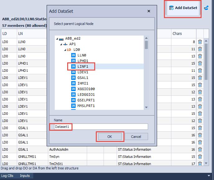
71 A user can filter an IED tree structure by a functional constraint. A user can add a new dataset by clicking on Add DataSet. The dialog box Add DataSet displays all IEDs which are capable of instantiating new datasets. A user needs to select a logical node where a new dataset will be created, enter the name, and then click on OK. page 71
72 page 72

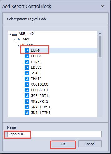
73 10.2. Report Control Blocks This table is opened by clicking on the DataFlow Engineering tab and then on the Report CBs subtab. It displays a list of report control blocks in the project grouped by IED. A user can edit the attributes of the report control blocks based on IED capabilities. A user can export this table in the following formats: XLSX, XLS, RTF, PDF, JPG. A user can add a new report control block by clicking on Add Report CB. The dialog box Add Report Control Block lists all IEDs which support the instantiation of a new report control block. A user needs to choose a logical node and a name of a new report control block and then click on OK. page 73
74 page 74
 and client IEDs (columns).")
75 10.3. Report Clients This table is opened by clicking on the DataFlow Engineering tab and then on the Report Clients subtab. It displays all report control blocks grouped by IED (rows) and client IEDs (columns). To set a client for a report control block, a user needs to click on an available checkbox in the same row as this control block. On the dialog box Select Logical Node user needs to choose a logical node on a selected client IED that will receive reports and click on OK. External references inside a client IED are automatically created. page 75

76 10.4. GOOSE Control Blocks This table is opened by clicking on the DataFlow Engineering tab and then on GOOSE CBs subtab. It displays a list of GOOSE control blocks in this project grouped by IED. A user can configure attributes of GOOSE control blocks based on IED capabilities. A user can create a new GOOSE control block by clicking on Add GOOSE CB. The dialog box Add GOOSE Control Block lists all IEDs in which the system configuration tool can instantiate a new GOOSE control block. A user needs to choose an LLN0 logical node in order to create a new GOOSE control block, enter a name and click on OK. page 76
77 10.5. GOOSE Subscribers This table is opened by clicking on DataFlow Engineering and then on GOOSE Subscribers. It displays GOOSE control blocks grouped by IED (rows) and IEDs with GOOSE subscribing capability (columns). To set a subscriber for a GOOSE control block, a user needs to click on an available checkbox in the same row as this control block. On the dialog box Select Logical Node a user needs to choose a logical node on the selected subscriber IED that will receive GOOSE messages and then click on OK. External references inside a subscriber IED are automatically created. A second option is to click on No LN. This means that the logical node that will receive GOOSE messages is not specified. page 77
78 10.6. Sampled Value Control Blocks This table is opened by clicking on the DataFlow Engineering tab and then on the Sampled Value CBs subtab. It displays sampled value control blocks in the project grouped by IED. A user can edit attributes of sampled value control blocks based on IED capabilities. A new sampled value control block can be instantiated by clicking on Add Sampled Value CB. The Dialog box Add Sampled Value Control Block lists all IEDs which support the instantiation of a new sampled value control block. A user needs to choose a logical node LLN0 in order to create a new sampled value control block, enter a name and then click on OK. page 78
79 10.7. Sampled Value Subscribers This table is opened by clicking on DataFlow Engineering and then on SV Subscribers. It displays sampled value control blocks grouped by IED (rows) and IEDs with sampled value subscribing capability (columns). To set a subscriber for a sampled value control block, a user needs to click on an available checkbox in the same row as this control block. On the dialog box Select Logical Node a user needs to choose a logical node on the selected subscriber IED that will receive sampled value messages and click on button OK. External references inside a subscriber IED are automatically created. A second option is to click on No LN. This means that the logical node that will receive sampled value messages is not specified. page 79
80 10.8. Log Control Blocks This table is opened by clicking on the DataFlow Engineering tab and then on Log CBs subtab. This table displays log control blocks in the current project grouped by IED. A user can modify attributes of log control blocks based on IED capabilities. A user can instantiate a new log control block by clicking on Add Log CB. The Add Log Control Block dialog box displays all IEDs which support the creation of new log control blocks. A user needs to choose a logical node in order to create new log control block, enter a name and click on OK. page 80

81 10.9. Inputs and External References This table is opened by clicking on the DataFlow Engineering tab and then on the Inputs subtab. It displays all external references grouped by IED. A user can manually add, modify and delete external references. A user can add a new external reference by clicking on Add External Reference. In the Add External Reference dialog box a user needs to select a logical node where the new external reference will be created and then click on OK. page 81

82 By clicking on Validate, all invalid fields will be marked with red. page 82

83 11. DataFlow Diagram Toolbox The toolbox is a container for buttons used for a dataflow diagram. Button Reload is used to reload a currently displayed dataflow diagram. The Filter Dialog is used to open the dialog for filtering of subnetworks and IEDs on the dataflow diagram. Buttons Draw/Remove All, Draw/Remove GOOSE, Draw/Remove Sampled Value, Draw/Remove Report are used to control the display of dataflow between IEDs. Zoom In, Zoom Out, Zoom To Fit, Zoom Normal and Zoom Overview are used for zoom operations. Print Preview and Print are used for print operations. page 83


84 11.2. Add IED 1. Right click on the dataflow diagram workspace and choose Add IED. 2. In the opened dialog box Import from file choose an SCL file from which to import an IED and click on Open. page 84

85 3. In the Import dialog box choose substations, subnetworks and IEDs to import and click on OK. A user can import more than one IED from an SCL file. Also, imported substations, subnetworks and IEDs can be renamed during import by changing their name in the Rename column. page 85


86 11.3. Rename IED 1. Right click on an IED on the dataflow diagram and choose Rename IED. 2. A dialog box Rename IED is opened. Enter a new name and click on button OK. page 86


87 11.4. Duplicate IED 1. Right click on an IED on the dataflow diagram and choose Duplicate IED. 2. Enter the name for the new IED and click on OK. page 87
88 11.5. Update IED 1. Right click on an IED on the dataflow diagram an choose Update IED. 2. In dialog box Open choose an SCL file to update an IED in the project and click on button Open. An IED in the file must have the same attributes name, manufacturer and type as the IED in the project. page 88


89 11.6. Export IED A user can export an IED into an SCL file and use this file as a template for the instantiation of additional IEDs in the project. 1. Right click on an IED on the dataflow diagram and choose 'Export IED'. Dialog box Save IED As is opened. 2. Choose a location where to save this file, enter the name, choose file extension, and click on Save. page 89

90 11.7. Add SubNetwork 1. Right click on an empty space on the dataflow diagram and choose Add SubNetwork. 2. A dialog box Add SubNetwork is opened. Enter the name for the subnetwork, choose the protocol type, enter the bitrate and description and click on OK. A new subnetwork is added into the project. page 90

 if it is supported by an IED Configuration of IP and OSI")
91 11.8. Modify Access Point Dialog box Modify Access Point can be opened by right clicking on an access point on the DataFlow Diagram and choosing Modify. Dialog box Modify Access Point is used for: Allocating an access point to a subnetwork Setting a redundancy protocol (PRP, HSR, RSTP) if it is supported by an IED Configuration of IP and OSI parameters of an access point page 91
92 11.9. Add DataSet 1. Right click on an empty space on the dataflow diagram workspace and choose Add DataSet. 2. The dialog box Add DataSet lists all IEDs which support the creation of datasets by the system configuration tool. A user needs to choose a logical node inside an IED in order to create a new dataset and name of the dataset. The name of the dataset must be unique inside a logical node. After the user clicks on OK, a new dataset is created. page 92

 or data attributes (DA) from the left")
93 Modify DataSet 1. Right click on a dataset inside an IED and choose Modify. Dialog box Modify DataSet is opened. 2. Dialog box Modify DataSet displays members of the selected dataset. New members are added by dragging and dropping data objects (DO) or data attributes (DA) from the left tree structure to the right table. After the user finishes editing the dataset, user needs to click on Close. page 93

94 Add Report Control Block 1. Right click on an empty space on the dataflow diagram and choose Add Report CB. The dialog box Add Report Control Block is opened. 2. The dialog box Add Report Control Block lists all IEDs which support the instantiation of a report control block by a system configuration tool. A user needs to choose a logical node and the name of the new report control block. After a user clicks on OK, the new report control block is created. page 94

95 Modify Report Control Block The dialog box Modify Report Control Block is opened by right clicking on a report control block and choosing Modify on the dataflow diagram. page 95

96 The dialog box Modify Report Control Block is used for the editing of report control block attributes based on IED capabilities. page 96

97 Configure Report Clients 1. Right click on a report control block inside an IED on the dataflow diagram and choose Configure Clients. 2. The dialog box Configure Report Clients lists all IEDs which are capable of receiving reports from this report control block. A user needs to click on a checkbox below the client IED. The dialog box Select Logical Node is opened. page 97


98 3. On the dialog box Select Logical Node a user needs to choose a logical node on a selected client IED that will receive reports and then click on OK. External references inside a client IED are automatically created. 4. Click on Close to close the dialog box Configure Report Clients. page 98

99 Add GOOSE Control Block 1. Right click on an empty space on the dataflow diagram and choose Add GOOSE CB. 2. The dialog box Add GOOSE Control Block lists all IEDs in which the system configuration tool can create a new GOOSE control block. A user needs to choose an LLN0 logical node in order to create a new GOOSE control block, enter the name and click on OK. page 99


100 Modify GOOSE Control Block 1. Right click on a GOOSE control block inside an IED on the dataflow diagram and choose Modify. 2. Change GOOSE control block attributes and click on button OK. Certain attributes can be unavailable based on IED capabilities. page 100
101 Configure GOOSE Subscribers 1. Right click on a GOOSE control block inside an IED on dataflow diagram and choose Configure Subscribers. 2. Dialog box Configure GOOSE Subscribers lists all IEDs which are capable of subscribing to GOOSE messages from this control block. A user needs to click on a checkbox below a subscriber IED. Dialog box Select Logical Node is opened. page 101

102 3. On dialog box Select Logical Node a user needs to choose a logical node on a selected subscriber IED that will receive GOOSE messages and click on OK. External references inside a subscriber IED are automatically created. A second option is to click on No LN. This means that the logical node that will receive GOOSE messages is not specified. 4. Click on Close to close the dialog box Configure GOOSE Subscribers. page 102

103 Add Sampled Value Control Block 1. Right click on an empty space on the dataflow diagram and choose Add Sampled Value CB. 2. Dialog box Add Sampled Value Control Block lists all IEDs which support the instantiation of a new sampled value control block. A user needs to choose a logical node LLN0 in order to create a new sampled value control block, enter the name and click on OK. page 103


104 Modify Sampled Value Control Block 1. Right click on a sampled value control block inside an IED on the dataflow diagram and choose Modify. 2. Change attributes of the sampled value control block and click on OK. Certain attributes are unavailable based on IED capabilities. page 104
105 Configure Sampled Value Subscribers 1. Right click on a sampled value control block inside an IED on the dataflow diagram and choose Configure Subscribers. 2. The dialog box Configure Sampled Value Subscribers lists all IEDs which are capable of subscribing to sampled value messages from this control block. User needs to click on a checkbox below the subscriber IED. page 105
106 3. On the dialog box Select Logical Node a user needs to choose a logical node on a selected subscriber IED that will receive sampled value messages and click on OK. External references inside a subscriber IED are automatically created. A second option is to click on No LN. This means that the logical node that will receive sampled value messages is not specified. 4. Click on Close to close the dialog box Configure Sampled Value Subscribers. page 106

107 Add Log Control Block 1. Right click on an empty space on the dataflow diagram and choose Add Log CB. 2. The dialog box Add Log Control Block displays all IEDs which support the instantiation of a new log control block. A user needs to choose a logical node in order to create a new log control block, enter the name and click on OK. page 107


108 Modify Log Control Block 1. Right click on a log control block inside an IED and choose Modify. 2. The dialog box Log Control Block displays attributes of the log control block. A user can change attributes based on IED capabilities and then click on OK. page 108


109 Draw Filter Dialog A user can control which elements to display on the dataflow diagram by using Filter Dialog. page 109
.")
110 Draw/Remove A user can control the display of GOOSE, sampled value and MMS communication on the dataflow diagram. Draw All displays all GOOSE, sampled value and MMS communication on the dataflow diagram. Draw GOOSE displays GOOSE communication on the dataflow diagram (represented in green). Draw Sampled Value displays sampled value communication on the dataflow diagram (represented in red). Draw Reports displays MMS communication on the dataflow diagram (represented in blue). Remove All removes all GOOSE, sampled value and MMS communication on the dataflow diagram. Remove GOOSE removes GOOSE communication on the dataflow diagram. Remove Sampled Value removes sampled value communication on the dataflow diagram. Remove Reports removes MMS communication on the dataflow diagram. page 110
 a user can filter only the dataflow from")
111 Control Block By double clicking on a control block (GCB, SVCB or RCB) a user can filter only the dataflow from this control block. By double clicking on the same control block again, the filter is deactivated. page 111


112 IED connections By right clicking on any IED and choosing Draw connections, a user can draw all connection from this IED. By right clicking on the same IED again and choosing Remove connections, a user cancels the display of connections from this IED. page 112
113 12. Export Validate Project A user can logically validate current project by clicking on button Validate Project on the Ribbon. Logical validation will check for: Unallocated IED access points Empty subnetworks Datasets without members Control blocks without referenced dataset Control blocks that reference dataset without members Log control blocks without referenced Log element Conflicting IP address page 113

114 12.2. Export SSD A user can export an SSD file in edition 2 or edition 1. When exporting in edition 1, all elements which are not available in edition 1 are automatically deleted. 1. Click on Export SSD (Edition 2) or Export SSD (Edition 1) on the Import/Export tab on the Ribbon. 2. In the dialog box 'Save SSD As' a user should choose a location to save the SSD file, enter the name and click on Save. page 114

. 1.")

115 12.3. Export SCD A user can export the SCD file in edition 2 or edition 1. When exporting in edition 1, all elements which are not available in edition 1 are automatically deleted. Exported files are valid according to the schema for edition 2 (2007 revision B) and for edition 1 (1.7). 1. Click on Export SCD (Edition 2) or Export SCD (Edition 1) on the Import/Export tab or Engineering Process tab on the Ribbon. 2. A message with warnings may be displayed (empty datasets, control blocks without datasets, unallocated IED access points, etc). A user should fix these errors before exporting an SCD file. The dialog box Save SCD As is opened and a user should choose a location to save the SCD file, enter the name and click on Save. page 115

116 12.4. Project Reports A user can print or export reports from the current project using the dialog box Project Reports. This dialog box is opened by clicking on the Project Reports button on the Ribbon. A user can: Print Export to PDF Export to RTF Export to Excel file (XLSX) page 116
.")

117 13. SED Handling The right of dataflow engineering can be formally transferred from one project to another by means of an SED file Export SED To export an SED file, go to the Import/Export tab on the Ribbon and click on the Export SED button. The warning is displayed if there is a pending SED import (an IED owned by the current project is already exported with dataflow engineering rights). Pending SED import can be cancelled by clicking on Reset checked-out IEDs. In a dialog Export SED a user chooses which IEDs to export with engineering rights (fix or dataflow). Only the owner project has full engineering rights. After user clicks on Export, a Save SED As dialog box is opened. page 117


118 A user needs to choose a location and name for the file and click on Save. page 118

119 13.2. Import SED To import an SED file a user needs to click on Import SED on the Import/Export tab on the Ribbon. The dialog box Import from SED file is opened. A user needs to select a file and click on button Open. After the application finishes the import of an SED file, a message is displayed. page 119


120 14. Settings Click on Settings on the Home tab on the Ribbon. Dialog box Settings is opened. page 120
121 Location where projects are stored. Change the set of symbols displayed on a single line diagram (IEC or ANSI standard). Change color scheme on single line diagram. Remove IED coordinates used for communication diagram positioning (attributes sxy:x and sxy:y). Change cable style on communication diagram. Change cable type colors and width on communication diagram. Only for advanced users. A user can bypass IED capabilities defined in the Services element and do dataflow engineering without restrictions. Services that are bypassed: ConfDataSet ConfLogControl ConfReportControl GOOSE GSESettings LogSettings ReportSettings SMVsc SMVSettings page 121
122 Only for advanced users. Bypass automatic SCL edition check during import. A user can manually choose the edition of the schema for validation. Only for advanced users. Bypass logic validation during import of SCL files. Elements will be imported without removal of invalid content. Invalid content include: Invalid Report clients (ClientLN elements) Invalid GOOSE subscribers (IEDName elements) Invalid Sampled Value subscribers (IEDName elements) Empty Inputs sections Only for advanced users. Bypass logic validation during the export of an SCD file. Invalid elements will not be removed in an exported SCD file. Invalid elements include: Unallocated IED access points Empty subnetworks Datasets without members Log control blocks without referenced Log element Reset all settings to default values. page 122
Annex G (normative) SCL Implementation Conformance Statement (SICS)
 SCL Implementation Conformance Statement (SICS)") Annex G (rmative) SCL Implementation Conformance Statement (SICS) This SICS is applicable for: Tool Name: IET600 ain role: SCT Version: 5.3 The following tables contain mandatory and features of System
Annex G (rmative) SCL Implementation Conformance Statement (SICS) This SICS is applicable for: Tool Name: IET600 ain role: SCT Version: 5.3 The following tables contain mandatory and features of System
RELEASE NOTE. Integrated Engineering Tool IET600 Ver. 5.3 Feature Pack 3
 RELEASE NOTE Integrated Engineering Tool IET600 Ver. 5.3 Feature Pack 3 2 IET600 VER. 5.3 FP3 RELEASE NOTE IET600 Ver. 5.3 FP3 Release Note Dear Reader, We are pleased to announce the release of IET600
InFusion SOFTWARE Product Specifications
 InFusion SOFTWARE Product Specifications Substation Automation Configuration for ArchestrA IDE BACKGROUND The IEC 61850 standard for communications in substations allows the development of multifunctional
RELEASE NOTE. Integrated Engineering Tool IET600 Ver. 5.3 Feature Pack 4
 RELEASE NOTE Integrated Engineering Tool IET600 Ver. 5.3 Feature Pack 4 2 IET600 VER. 5.3 FP4 RELEASE NOTE IET600 Ver. 5.3 FP4 Release Note Dear Reader, We are pleased to announce the release of IET600
ERL IED Configurator
 ERL 61850 IED Configurator User Manual Version 2.0 Rev 1 Preface Information in this document is subject to change without notice. 2015 ERLPhase Power Technologies Ltd. All rights reserved. Reproduction
Substation Configuration Language. Summary August 2006
 Substation Configuration Language Summary August 2006 CONFIGURATION SCL Format Defined in IEC 61850 Part 6 Four different file types System Specification Description (SSD) power system functions Substation
Overview and Application
 IEC 61850 Overview and Application Who am I? Rich Hunt Market Development Leader GE Grid Solutions Over 25 years in the power systems industry At GE for 10 years (almost) Member of IEEE PSRC, U.S. Representative
IED Configurator. User Manual
 SystemCORP Embedded Technology Pty Ltd This PDF Document contains internal hyperlinks for ease of navigation. For example, click on any item listed in the Table of Contents to go to that page. General
SCL Manager An Engineering & Configuration tool based on IEC
 6000 SCL Manager An Engineering & Configuration tool based on IEC61850 www.kalkitech.com About Kalkitech Kalki Communication Technologies Limited (Kalkitech) is a technology based company founded in 1998,
Specification Manager
 Enterprise Architect User Guide Series Specification Manager Author: Sparx Systems Date: 30/06/2017 Version: 1.0 CREATED WITH Table of Contents The Specification Manager 3 Specification Manager - Overview
Specification Manager
 Enterprise Architect User Guide Series Specification Manager How to define model elements simply? In Sparx Systems Enterprise Architect, use the document-based Specification Manager to create elements
GIMP ANIMATION EFFECTS
 GIMP ANIMATION EFFECTS Animation: Text Word by Word ANIMATION: TEXT WORD BY WORD GIMP is all about IT (Images and Text) BACKGROUND IMAGE Before you begin the text animation, you will download a public
GreenFolders User Manual
 GreenFolders User Manual Welcome! Welcome to GreenFolders the Electronic Records Management Solution. GreenFolders allows you to store and retrieve files with many easy-to-use features for working with
WAIPA DISTRICT COUNCIL. Maps Online 9. Updated January This document contains an overview of IntraMaps/Maps Online version 9.
 WAIPA DISTRICT COUNCIL Maps Online 9 Updated January 2018 This document contains an overview of IntraMaps/Maps Online version 9.0 Contents Starting Maps Online... 3 Menu Bar... 4 Tools... 5 View Tab...
Working with PDF s. To open a recent file on the Start screen, double click on the file name.
 Working with PDF s Acrobat DC Start Screen (Home Tab) When Acrobat opens, the Acrobat Start screen (Home Tab) populates displaying a list of recently opened files. The search feature on the top of the
IBM TRIRIGA Application Platform Version 3.2. Graphics User Guide. Copyright IBM Corp i
 IBM TRIRIGA Application Platform Version 3.2 Graphics User Guide Copyright IBM Corp. 2011 i Note Before using this information and the product it supports, read the information in Notices on page 31. This
User Guide DYMO Label TM v.8
 User Guide DYMO Label TM v.8 Copyright Trademarks 2012-2015 Sanford, L.P. All rights reserved. Revised 9/6/2016. No part of this document or the software may be reproduced or transmitted in any form or
Getting_started_EN (Ind : 3) 06/01/2014. elecworks. Getting Started
 06/01/2014. elecworks. Getting Started") Getting_started_EN (Ind : 3) 06/01/2014 elecworks Getting Started 1 Start with elecworks This document has been made to help you in starting elecworks. It summarizes the features available. If you would
Getting_started_EN (Ind : 3) 06/01/2014 elecworks Getting Started 1 Start with elecworks This document has been made to help you in starting elecworks. It summarizes the features available. If you would
Work Smart: Microsoft Office 2010 User Interface
 About the Office 2010 User Interface You can use this guide to learn how to use the new features of the Microsoft Office Ribbon. Topics in this guide include: What s New in the Office 2010 User Interface
Spatial Data Standards for Facilities, Infrastructure, and Environment (SDSFIE)
") Spatial Data Standards for Facilities, Infrastructure, and Environment (SDSFIE) Model Builder User Guide Version 1.3 (24 April 2018) Prepared For: US Army Corps of Engineers 2018 Revision History Model
Spatial Data Standards for Facilities, Infrastructure, and Environment (SDSFIE) Model Builder User Guide Version 1.3 (24 April 2018) Prepared For: US Army Corps of Engineers 2018 Revision History Model
v Annotation Tools GMS 10.4 Tutorial Use scale bars, North arrows, floating images, text boxes, lines, arrows, circles/ovals, and rectangles.
 v. 10.4 GMS 10.4 Tutorial Use scale bars, North arrows, floating images, text boxes, lines, arrows, circles/ovals, and rectangles. Objectives GMS includes a number of annotation tools that can be used
SPECIFICATIONS FOR SCL(SUBSTATION CONFIGURATION LANGUAGE) MANAGER WITH HYDRO DATA MODELS A. GENERAL SPECIFICATIONS
 MANAGER WITH HYDRO DATA MODELS A. GENERAL SPECIFICATIONS") A. GENERAL SPECIFICATIONS A.1 General Conformance: The SCL (Substation Configuration Language) Manager configuration utility tool provided by the vender for configuring an IED( Intelligent Electronic Device)
A. GENERAL SPECIFICATIONS A.1 General Conformance: The SCL (Substation Configuration Language) Manager configuration utility tool provided by the vender for configuring an IED( Intelligent Electronic Device)
Monitoring and Evaluation Tool
 Monitoring and Evaluation Tool USER MANUAL March, 2014 www.menarid.icarda.org THIS PAGE LEFT EMPTY INTENTIONALLY USER MANUAL Definitions and abbreviations Chart... Graphical representation of M&E project
IBM Rational Rhapsody Gateway Add On. User Guide
 User Guide Rhapsody IBM Rational Rhapsody Gateway Add On User Guide License Agreement No part of this publication may be reproduced, transmitted, stored in a retrieval system, nor translated into any
Vela Web User Guide Vela Systems, Inc. All rights reserved.
 The Vela Systems Web application is designed to enable the administration, management, and reporting of the Vela Field Management Suite, as well as give project teams the ability to collaborate on issues,
Introduction to Qualtrics ITSC
 Introduction to Qualtrics ITSC August 2015 Contents A. General Information... 4 B. Login... 5 New Qualtrics User... 5 Existing Qualtrics User... 7 C. Navigating Qualtrics... 9 D. Create Survey... 10 Quick
Impress Guide Chapter 11 Setting Up and Customizing Impress
 Impress Guide Chapter 11 Setting Up and Customizing Impress This PDF is designed to be read onscreen, two pages at a time. If you want to print a copy, your PDF viewer should have an option for printing
Contents... 1 Installation... 3
 Contents Contents... 1 Installation... 3 1 Prerequisites (check for.net framework 3.5)... 3 Install Doctor Eye... 3 Start Using Doctor Eye... 4 How to create a new user... 4 The Main Window... 4 Open a
Managing Content with AutoCAD DesignCenter
 Managing Content with AutoCAD DesignCenter In This Chapter 14 This chapter introduces AutoCAD DesignCenter. You can now locate and organize drawing data and insert blocks, layers, external references,
23 - Report & Export
 23 - Report & Export Contents 23 - REPORT & EXPORT... 1 SMART PUBLISHER... 1 Opening Smart Publisher... 1 Smart Publisher Settings... 2 The Finished Report... 5 Alias Names for Codes... 6 The Word Template
UMHS Financial Systems Workspace & Smart View Templates
 Level 1 Password https://findatamgr.dsc.umich.edu/workspace/index.jsp What If I have a blank Homepage? Utilize the Use Current Page button to set the Home Page. Why do I not see the Preview User Point
User Guide. Web Intelligence Rich Client. Business Objects 4.1
 User Guide Web Intelligence Rich Client Business Objects 4.1 2 P a g e Web Intelligence 4.1 User Guide Web Intelligence 4.1 User Guide Contents Getting Started in Web Intelligence 4.1... 5 Log into EDDIE...
MPLAB Harmony Help - MPLAB Harmony Graphics Composer User's Guide
 MPLAB Harmony Help - MPLAB Harmony Graphics Composer User's Guide MPLAB Harmony Integrated Software Framework v1.11 2013-2017 Microchip Technology Inc. All rights reserved. MPLAB Harmony Graphics Composer
INTRODUCTION... 3 INSTALLATION GUIDE FOR ECLIPSE 3.1 AND INSTALLATION GUIDE FOR ECLIPSE 3.3 TO
 INTRODUCTION... 3 INSTALLATION GUIDE FOR ECLIPSE 3.1 AND 3.2... 4 INSTALLATION GUIDE FOR ECLIPSE 3.3 TO 4.3... 23 INSTALLATION GUIDE FOR ECLIPSE 4.4 OR HIGHER... 37 ECLIPSE VIEWERS... 41 DEVICES... 41
Quark XML Author for FileNet 2.8 with BusDocs Guide
 Quark XML Author for FileNet.8 with BusDocs Guide Contents Getting started... About Quark XML Author... System setup and preferences... Logging on to the repository... Specifying the location of checked-out
SPARK. User Manual Ver ITLAQ Technologies
 SPARK Forms Builder for Office 365 User Manual Ver. 3.5.50.102 0 ITLAQ Technologies www.itlaq.com Table of Contents 1 The Form Designer Workspace... 3 1.1 Form Toolbox... 3 1.1.1 Hiding/ Unhiding/ Minimizing
User Guide. BlackBerry Workspaces for Windows. Version 5.5
 User Guide BlackBerry Workspaces for Windows Version 5.5 Published: 2017-03-30 SWD-20170330110027321 Contents Introducing BlackBerry Workspaces for Windows... 6 Getting Started... 7 Setting up and installing
Ektron Advanced. Learning Objectives. Getting Started
 Ektron Advanced 1 Learning Objectives This workshop introduces you beyond the basics of Ektron, the USF web content management system that is being used to modify department web pages. This workshop focuses
Create a Customised Tab on the Office 2013 Ribbon
 Create a Customised Tab on the Office 2013 Ribbon Office 2007 saw the addition of the Ribbon feature, which some users found confusing. However, you can use it to your advantage by adding your own custom
WHCC Sports and Events
 WHCC Sports and Events We re using ROES Events as our ordering software for Sports and Events. This is a special version of ROES, written specifically for high volume events. There are two primary differences
IBM TRIRIGA Application Platform Version 3.3. Graphics User Guide. Copyright IBM Corp i
 IBM TRIRIGA Application Platform Version 3.3 Graphics User Guide Copyright IBM Corp. 2011 i Note Before using this information and the product it supports, read the information in Notices on page 33. This
TECHNICAL COMMITTEE 57: POWER SYSTEMS MANAGEMENT AND ASSOCIATED INFORMATION EXCHANGE
 For IEC use only 57/1919/INF 2017-09-15 INTERNATIONAL ELECTROTECHNICAL COMMISSION TECHNICAL COMMITTEE 57: POWER SYSTEMS MANAGEMENT AND ASSOCIATED INFORMATION EXCHANGE Consolidated Edition 2.1 of IEC 61850-6:
User Guide 701P Wide Format Solution Wide Format Scan Service
 User Guide 701P44865 6204 Wide Format Solution Wide Format Scan Service Xerox Corporation Global Knowledge & Language Services 800 Phillips Road Bldg. 845-17S Webster, NY 14580 Copyright 2006 Xerox Corporation.
Receipt Gallery. Receipt Gallery Instructions. Page 1 of 11
 Page 1 of 11 Receipt Gallery The Receipt Gallery is accessible from the main menu (via the ereceipts button) and the Add Expenses panel and contains all the emailed receipt images sent to receipt@chromefile.com,
CPM-200 User Guide For Lighthouse for MAX
 CPM-200 User Guide For Lighthouse for MAX Contents Page Number Opening the software 2 Altering the page size & Orientation 3-4 Inserting Text 5 Editing Text 6 Inserting Graphics 7-8 Changing the Colour
From the dock at the left, right, top, or bottom of your monitor screen, open the Finder.
 GETTING STARTED Composition & Defamiliarization: Using Adobe Illustrator as a Tool Kristen Foster 2010 Drawing and Composition Module OTIS College of Art and Design Trash preferences + Open Illustrator
Microsoft Access 2013
 Microsoft Access 2013 Chapter 2 Querying a Database Objectives Create queries using Design view Include fields in the design grid Use text and numeric data in criteria Save a query and use the saved query
Microsoft Access 2013
 Microsoft Access 2013 Chapter 2 Querying a Database Objectives Create queries using Design view Include fields in the design grid Use text and numeric data in criteria Save a query and use the saved query
Imagine. Create. Discover. User Manual. TopLine Results Corporation
 Imagine. Create. Discover. User Manual TopLine Results Corporation 2008-2009 Created: Tuesday, March 17, 2009 Table of Contents 1 Welcome 1 Features 2 2 Installation 4 System Requirements 5 Obtaining Installation
IBM Rational Rhapsody Gateway Add On. User Manual
 User Manual Rhapsody IBM Rational Rhapsody Gateway Add On User Manual License Agreement No part of this publication may be reproduced, transmitted, stored in a retrieval system, nor translated into any
SimFlex HMI Simulator. User Manual
 SimFlex HMI Simulator User Manual 1 Index 1 Index... 1 1.1 What is SimFlex HMI Simulator?... 3 1.2 Benefits... 3 1.3 Applications... 3 1.4 Key Features... 3 1.5 Basic skill requirements... 3 1.6 SCL file
Quark XML Author October 2017 Update for Platform with Business Documents
 Quark XML Author 05 - October 07 Update for Platform with Business Documents Contents Getting started... About Quark XML Author... Working with the Platform repository...3 Creating a new document from
Reporting Center. Primary (Stand-Alone) Interface
 Interface") Reporting Center The Reporting Center is where you will go to run or create reports on projects. It can be accessed in any of the follow ways, each with a slightly different user interface and functionality.
Reporting Center The Reporting Center is where you will go to run or create reports on projects. It can be accessed in any of the follow ways, each with a slightly different user interface and functionality.
Excel Select a template category in the Office.com Templates section. 5. Click the Download button.
 Microsoft QUICK Excel 2010 Source Getting Started The Excel Window u v w z Creating a New Blank Workbook 2. Select New in the left pane. 3. Select the Blank workbook template in the Available Templates
CostX 6.5 Release Notes
 CostX 6.5 Release Notes Overview CostX version 6.5 is an exciting new development in the Exactal range of world-class digital measurement and estimating software. In addition to many new features and improvements
vbound User Guide vbound User Guide Version Revised: 10/10/2017
 vbound User Guide Version 4.1.1 Revised: 10/10/2017 Copyright 2014-2017 FFL Solutions Inc. Page 1 of 87 Table of Contents Using vbound...5 Starting vbound... 5 Bound Book List... 6 vbound Ribbon Menu...
Name: Date: June 27th, 2011 GIS Boot Camps For Educators Lecture_3
 Name: Date: June 27th, 2011 GIS Boot Camps For Educators Lecture_3 Practical: Creating and Editing Shapefiles Using Straight, AutoComplete and Cut Polygon Tools Use ArcCatalog to copy data files from:
For best results, ensure that the VST is the only browser instance running and fully close the browser each time before accessing the VST again.
 This User Guide summarizes the interface and components of the Valve and Actuator Selection Tool. PDF viewing: If you are viewing this PDF from the browser, easily navigate this document using the Bookmarks
Contents. Announcer Pro Version 4.6 Page 2 of 35 Version V4.6
 User Guide Contents 1. Introduction... 3 1.1. Getting Started... 3 1.2. Navigation... 4 2. Create a Newsletter... 6 2.1. Confirm Company Details... 6 2.2. Choose Template... 8 2.3. Edit Newsletter... 8
Quark XML Author for FileNet 2.5 with BusDocs Guide
 Quark XML Author for FileNet 2.5 with BusDocs Guide CONTENTS Contents Getting started...6 About Quark XML Author...6 System setup and preferences...8 Logging in to the repository...8 Specifying the location
1. Concepts and What s New Concepts What's New in E Getting Started Starting Electra Page Scale
 1 1. Concepts and What s New... 6 1.1 Concepts... 6 1.2 What's New in E6... 7 2. Getting Started... 8 2.1 Starting Electra... 8 2.2 Page Scale... 8 2.3 Page Measurement Units... 9 2.4 Stencils and Drawing
Workshop on Census Data Processing. TELEform Designer User Manual
 Workshop on Census Data Processing TELEform Designer User Manual Contents TELEFORM MODULES... 1 TELEFORM DESIGNER MODULE... 1 FORM TEMPLATES... 1 Available Form Templates... 2 THE DESIGNER WORKSPACE...
Add notes to a document
 Add notes to a document WX and AX Add notes to a document Web Access (WX) and Document Manager (AX) In, you can mark up a document using the annotation toolbar. With these tools, you are able to add typewritten
Word 2013 Quick Start Guide
 Getting Started File Tab: Click to access actions like Print, Save As, and Word Options. Ribbon: Logically organize actions onto Tabs, Groups, and Buttons to facilitate finding commands. Active Document
INFORMZ USER GUIDE: The Asset Manager
 INFORMZ USER GUIDE: The Asset Manager Version 1.0 January 29, 2014 ABOUT THIS GUIDE This guide provides an overview of the Asset Manager used by Informz. This guide covers the Asset Manager s basic functionality
P3e REPORT WRITER CREATING A BLANK REPORT
 P3e REPORT WRITER CREATING A BLANK REPORT 1. On the Reports window, select a report, then click Copy. 2. Click Paste. 3. Click Modify. 4. Click the New Report icon. The report will look like the following
Easergy Studio V8.0.0 Release Notes
 Easergy Studio V8.0.0 Release Notes Document date: Version: 26/March/2018 A 1 1 About release V8.0.0 This release provides a full installation of Schneider-Electric Easergy Studio V8.0.0. - It supersets
Acrobat X Professional
 Acrobat X Professional Toolbar Well Page Navigations/Page Indicator Buttons for paging through document Scroll Bar/box page indicator appears when using the scroll button to navigate. When you release
Send documentation feedback to Supported Functionalities - Switches and IEDs
 CHAPTER 4 The CGDS Designer allows you create a substation topology. The Cisco Connected Grid Design Suite (CGDS) application allows you to design the integrated substation LAN by analyzing configurations
Scheduler Plug-In PTC Inc. All Rights Reserved.
 2018 PTC Inc. All Rights Reserved. 2 Table of Contents 1 Table of Contents 2 4 Plug-In Interface 5 Schedule Properties 7 Exception / Recurrence Group - General Properties 7 Recurrence General Properties
How to Mail Merge PDF Documents
 How to Mail Merge PDF Documents A step-by-step guide to creating personalized documents using AutoMailMerge plug-in for Adobe Acrobat Table of Contents What is a mail merge?...2 What do I need to start?...2
COMMUNITIES USER MANUAL. Satori Team
 COMMUNITIES USER MANUAL Satori Team Table of Contents Communities... 2 1. Introduction... 4 2. Roles and privileges.... 5 3. Process flow.... 6 4. Description... 8 a) Community page.... 9 b) Creating community
Using Adobe Contribute 4 A guide for new website authors
 Using Adobe Contribute 4 A guide for new website authors Adobe Contribute allows you to easily update websites without any knowledge of HTML. This handout will provide an introduction to Adobe Contribute
How Smart Are Your Tables? Jeanne Aarhus Aarhus Associates, LLC
 How Smart Are Your Tables? Jeanne Aarhus Aarhus Associates, LLC AC2251-L Are you using tables in AutoCAD software to their fullest potential? Do you still manually collect data from your AutoCAD file,
Quark XML Author September 2016 Update for Platform with Business Documents
 Quark XML Author 05 - September 06 Update for Platform with Business Documents Contents Getting started... About Quark XML Author... Working with the Platform repository... Creating a new document from
InDesign Part II. Create a Library by selecting File, New, Library. Save the library with a unique file name.
 InDesign Part II Library A library is a file and holds a collection of commonly used objects. A library is a file (extension.indl) and it is stored on disk. A library file can be open at any time while
SCL Tool. Configuration manual
 REF 542plus 1MRS756342 Issued: 30.04.2007 Version: A/31.05.2007 REF 542plus Contents Copyrights... 5 1. Introduction...7 1.1. This manual... 7 1.2. Use of symbols... 7 1.3. Product documentation... 8
FlowJo Software Lecture Outline:
 FlowJo Software Lecture Outline: Workspace Basics: 3 major components 1) The Ribbons (toolbar) The availability of buttons here can be customized. *One of the best assets of FlowJo is the help feature*
Numbers Basics Website:
 Website: http://etc.usf.edu/te/ Numbers is Apple's new spreadsheet application. It is installed as part of the iwork suite, which also includes the word processing program Pages and the presentation program
Report Designer Report Types Table Report Multi-Column Report Label Report Parameterized Report Cross-Tab Report Drill-Down Report Chart with Static
 Table of Contents Report Designer Report Types Table Report Multi-Column Report Label Report Parameterized Report Cross-Tab Report Drill-Down Report Chart with Static Series Chart with Dynamic Series Master-Detail
USER GUIDE. Forms & Surveys. Schoolwires Centricity
 USER GUIDE Schoolwires Centricity TABLE OF CONTENTS Introduction... 1 Audience and Objectives... 1 Major Components of a Form or Survey... 2 Overview... 2 Manage... 3 New Forms/Surveys... 3 Item Libraries...
Adobe Encore DVD Tutorial:
 Adobe Encore DVD Tutorial: Here is a simple tutorial for creating DVDs which will play Dolby Digital audio: 1. Plan the DVD project. Think through your DVD project. Decide how many audio tracks you want
SMART Recorder. Record. Pause. Stop
 SMART Recorder The recorder is used to record actions that are done on the interactive screen. If a microphone is attached to the computer, narration can be recorded. After the recording has been created,
Contents. Common Site Operations. Home actions. Using SharePoint
 This is a companion document to About Share-Point. That document describes the features of a SharePoint website in as much detail as possible with an emphasis on the relationships between features. This
Dive Into Visual C# 2008 Express
 1 2 2 Dive Into Visual C# 2008 Express OBJECTIVES In this chapter you will learn: The basics of the Visual Studio Integrated Development Environment (IDE) that assists you in writing, running and debugging
Icon Directory. Action Icons. Icon Name Description
 Icon Directory The icons found on the various MasterControl pages are listed according to their general location on a given page. For instance, Action Icons usually are found in columns headed "Action".
User guide. PRISMAdirect Order processing
 User guide PRISMAdirect Order processing Copyright 2016, Océ All rights reserved. No part of this work may be reproduced, copied, adapted, or transmitted in any form or by any means without written permission
This user guide covers select features of the desktop site. These include:
 User Guide myobservatory Topics Covered: Desktop Site, Select Features Date: January 27, 2014 Overview This user guide covers select features of the desktop site. These include: 1. Data Uploads... 2 1.1
Producing Project Deliverables: Creating a Plan Set
 Practice Workbook This workbook is designed for use in Live instructor-led training and for OnDemand selfstudy. The explanations and demonstrations are provided by the instructor in the classroom, or in
CGDS - Substation Workbench Release 1.0 Browser Role User Guide
 Browser Role User Guide Revised: June 19, 2013 CGDS - Substation Workbench Release 1.0 Substation Workbench Browser Role The Browser Role in CGDS - Substation Workbench has the capabilities needed to monitor
Using Sitecore 5.3.1
 Using Sitecore 5.3.1 An End-User s Guide to Using and Administrating Sitecore Author: Sitecore Corporation Date: December 12, 2007 Release: Rev. 1.0 Language: English Sitecore is a registered trademark.
for ArcSketch Version 1.1 ArcSketch is a sample extension to ArcGIS. It works with ArcGIS 9.1
 ArcSketch User Guide for ArcSketch Version 1.1 ArcSketch is a sample extension to ArcGIS. It works with ArcGIS 9.1 ArcSketch allows the user to quickly create, or sketch, features in ArcMap using easy-to-use
B-1122(7) Tutorial Guide
 Tutorial Guide") B-1122(7) Tutorial Guide Introduction Caution The contents of this manual and the WindCFG application are copyright, and all rights are reserved by IDEC Corporation. Unauthorized reproduction is prohibited.
B-1122(7) Tutorial Guide Introduction Caution The contents of this manual and the WindCFG application are copyright, and all rights are reserved by IDEC Corporation. Unauthorized reproduction is prohibited.
Solo 4.6 Release Notes
 June9, 2017 (Updated to include Solo 4.6.4 changes) Solo 4.6 Release Notes This release contains a number of new features, as well as enhancements to the user interface and overall performance. Together
Polaris Office 4.0 User Help Guide for ios
 Polaris Office 4.0 User Help Guide for ios I. Overview 1. Polaris Office 4.0 overview Polaris Office 4.0 is a powerful and easy-to-use office product designed for mobile devices. You can create a document,
Creating electrical designs
 Creating electrical designs 27.09.2018-34 TABLE OF CONTENTS Table of contents... 2 Introduction... 4 What you learn with this content... 5 Starting G-Electrical... 6 Interface... 6 Drawing area (1)...
Abstract. For notes detailing the changes in each release, see the MySQL for Excel Release Notes. For legal information, see the Legal Notices.
 MySQL for Excel Abstract This is the MySQL for Excel Reference Manual. It documents MySQL for Excel 1.3 through 1.3.7. Much of the documentation also applies to the previous 1.2 series. For notes detailing
What s New in Cognos. Cognos Analytics Participant s Guide
 What s New in Cognos Cognos Analytics Participant s Guide Welcome to What s New in Cognos! Illinois State University has undergone a version upgrade of IBM Cognos to Cognos Analytics. All functionality
EZCT-2000 Software. VERSION 2.x USER'S MANUAL
 EZCT-2000 Software VERSION 2.x USER'S MANUAL For Use with Vanguard s EZCT-S2, EZCT-S2A, EZCT-2000, EZCT-2000A, EZCT-2000B, EZCT-2KA, EZCT-2000C Current Transformer Testers Vanguard Instruments Company,
GraffixPro Studio TM Software Version 2.0 Release Notes
 GraffixPro Studio TM Software Version 2.0 Release Notes February 2013 2 NEW TO GRAFFIXPRO STUDIO TM SOFTWARE VERSION 2.0: The following is a brief description of the features and functionality that are