FUJITSU Storage ETERNUS SF Storage Cruiser V16.5. Operation Guide
|
|
|
- Randolf Melton
- 6 years ago
- Views:
Transcription

")
1 FUJITSU Storage ETERNUS SF Storage Cruiser V16.5 Operation Guide B1FW ENZ0(00) May 2017
2 Preface Purpose This manual describes how to use FUJITSU Storage ETERNUS SF Storage Cruiser (hereafter abbreviated as "Storage Cruiser"). Intended Readers The manual is intended for operations managers who use Storage Cruiser for storage management. The procedure used for actual system configuration assumes that the reader knows the basic configuration procedure for the installation target server, storage units, and their network. Organization This manual is composed as follows: Chapter 1 Overview Explains the ETERNUS SF Storage Cruiser. Chapter 2 Fault Monitoring Explains how to detect errors occurring in the devices making up a storage system, the screen displayed for them, and how to respond to them. Chapter 3 Operation Design Explains LAN connections. Chapter 4 Environment Configuration Provides the settings and notes required for devices to be managed. Chapter 5 Startup and Setting Provides device definitions and operation flowcharts required for operating this product software. Chapter 6 Operation Explains how to use each view of the resource view and Correlation window. Chapter 7 Performance Management Explains performance management functions. Chapter 8 Reporting Function Explains reporting functions. Chapter 9 Storage Cluster Function Explains Storage Cluster functions. Chapter 10 Maintenance of Devices to Be Managed Explains the screen displayed at the occurrence of a device error and how to respond to it. Chapter 11 Maintenance of Administrative Environment Explains how to maintain databases and the troubleshooting required if a problem occurs. Chapter 12 Linkage to Other Software Explains how to link with other software. Chapter 13 Command References Explains how to use each command. Appendix A Customization Explains how to customize definition files. - i -
3 Appendix B Troubleshooting Explains basic troubleshooting and also provides information on where to find further help. Appendix C How to Check Product Version Explains how to check version of installed ETERNUS SF Storage Cruiser. Appendix D Operations Other Than Operations on Switches within System Managed on Storage Cruiser Explains the operation points in cases when managing the system configuration storage devices and servers including switches not supported by Storage Cruiser. Appendix E Settings of Encryption Algorithm in SNMPv3 Protocol Notation This appendix explains settings of encryption algorithm in SNMPv3 protocol. The names, abbreviations, and symbols shown below are used in this manual. Operating Systems Formal Name Microsoft(R) Windows Server(R) 2008 Standard (32-bit)(64-bit) Microsoft(R) Windows Server(R) 2008 Standard without Hyper-V(TM) (32-bit) (64-bit) Microsoft(R) Windows Server(R) 2008 Enterprise (32-bit)(64-bit) Microsoft(R) Windows Server(R) 2008 Enterprise without Hyper-V(TM) (32-bit) (64-bit) Microsoft(R) Windows Server(R) 2008 Datacenter (32-bit)(64-bit) Microsoft(R) Windows Server(R) 2008 Datacenter without Hyper-V(TM) (32-bit) (64-bit) Microsoft(R) Windows Server(R) 2008 R2 Foundation Microsoft(R) Windows Server(R) 2008 R2 Standard Microsoft(R) Windows Server(R) 2008 R2 Enterprise Microsoft(R) Windows Server(R) 2008 R2 Datacenter Microsoft(R) Windows Server(R) 2012 Standard Microsoft(R) Windows Server(R) 2012 Datacenter Microsoft(R) Windows Server(R) 2012 R2 Standard Microsoft(R) Windows Server(R) 2012 R2 Datacenter Microsoft(R) Windows Server(R) 2016 Standard Microsoft(R) Windows Server(R) 2016 Datacenter Windows(R) 7 Home Basic Windows(R) 7 Home Premium Windows(R) 7 Professional Windows(R) 7 Enterprise Windows(R) 7 Ultimate Windows(R) 8 Windows(R) 8 Pro Windows(R) 8.1 Windows(R) 8.1 Pro Windows(R) 10 Home Windows(R) 10 Pro Windows(R) 10 Mobile Abbreviation Windows Server 2008 Windows Server 2008 R2 Windows Server 2012 Windows Server 2012 R2 Windows Server 2016 Windows 7 Windows 8 Windows 8.1 Windows 10 Windows Solaris(TM) 9 Operating System Solaris 9 Solaris or Oracle Solaris 10 Solaris 10 Solaris OS - ii -
4 Formal Name Abbreviation Oracle Solaris 11 Solaris 11 Red Hat(R) Enterprise Linux(R) 5 (for x86) Red Hat(R) Enterprise Linux(R) 5 (for Intel64) Red Hat(R) Enterprise Linux(R) 6 (for x86) Red Hat(R) Enterprise Linux(R) 6 (for Intel64) Red Hat(R) Enterprise Linux(R) 7 (for Intel64) SUSE(R) Linux Enterprise Server 12 for AMD64 & Intel64 HP-UX 11i v3 AIX(R) V6.1 AIX(R) V7.1 RHEL5 RHEL6 RHEL7 SUSE Linux Enterprise Server 12 HP-UX AIX Linux VMware vsphere(r) 5 VMware vsphere 5 VMware VMware vsphere(r) 6 VMware vsphere 6 Oracle Solaris might be described as Solaris, Solaris Operating System, or Solaris OS. FUJITSU Storage ETERNUS Formal Name Abbreviation FUJITSU Storage ETERNUS DX ETERNUS DX FUJITSU Storage ETERNUS DX410 FUJITSU Storage ETERNUS DX440 FUJITSU Storage ETERNUS DX8100 FUJITSU Storage ETERNUS DX8400 FUJITSU Storage ETERNUS DX8700 ETERNUS DX400 series ETERNUS DX8000 series series or ETERNUS Disk storage system FUJITSU Storage ETERNUS DX60 S2 FUJITSU Storage ETERNUS DX80 S2 FUJITSU Storage ETERNUS DX90 S2 FUJITSU Storage ETERNUS DX410 S2 FUJITSU Storage ETERNUS DX440 S2 FUJITSU Storage ETERNUS DX8100 S2 FUJITSU Storage ETERNUS DX8700 S2 FUJITSU Storage ETERNUS DX60 S3 FUJITSU Storage ETERNUS DX100 S3 FUJITSU Storage ETERNUS DX200 S3 FUJITSU Storage ETERNUS DX500 S3 FUJITSU Storage ETERNUS DX600 S3 FUJITSU Storage ETERNUS DX8700 S3 FUJITSU Storage ETERNUS DX8900 S3 FUJITSU Storage ETERNUS DX60 S4 FUJITSU Storage ETERNUS DX100 S4 FUJITSU Storage ETERNUS DX200 S4 FUJITSU Storage ETERNUS AF250 FUJITSU Storage ETERNUS AF650 - ETERNUS DX S2 series ETERNUS DX400 S2 series ETERNUS DX8000 S2 series - ETERNUS DX S3 series - ETERNUS DX8000 S3 series - ETERNUS DX S4 series ETERNUS AF series ETERNUS All- Flash Arrays FUJITSU Storage ETERNUS DX200F - FUJITSU Storage ETERNUS LT20/LT20 S2 FUJITSU Storage ETERNUS LT40/LT40 S2 ETERNUS Tape library - iii -
5 Formal Name FUJITSU Storage ETERNUS LT60 S2 FUJITSU Storage ETERNUS LT200 FUJITSU Storage ETERNUS LT210 FUJITSU Storage ETERNUS LT220 FUJITSU Storage ETERNUS LT230 FUJITSU Storage ETERNUS LT250 FUJITSU Storage ETERNUS LT260 FUJITSU Storage ETERNUS LT270/LT270 S2 Abbreviation FUJITSU Storage ETERNUS Multipath Driver ETERNUS Multipath Driver Each individual device name in this document is listed with "FUJITSU Storage" omitted from it. NetApp FAS Series and V-Series are abbreviated as follows. Firmware Version String Included in Firmware Name Abbreviation Data ONTAP 6.x Data ONTAP 7.x Data ONTAP x (Any string) 7-Mode NetApp FAS Series NetApp V-Series Data ONTAP x Cluster-Mode NetApp FAS Series (with clustered Data ONTAP) Data ONTAP 8.3 or later (Any string) NetApp V-Series (with clustered Data ONTAP) Software Products Formal Name Windows(R) Internet Explorer(R) Mozilla(R) Firefox(R) Google Chrome(TM) Microsoft(R) Windows Server(R) Failover Clustering Microsoft(R) Exchange Server Microsoft(R) SQL Server(R) VMware(R) ESX(R) VMware(R) ESXi(TM) VMware(R) vcenter(tm) Server FUJITSU Storage ETERNUS SF Express FUJITSU Storage ETERNUS SF AdvancedCopy Manager FUJITSU Software PRIMECLUSTER Global Disk Services FUJITSU Software PRIMECLUSTER Global File Services Abbreviation Internet Explorer Firefox Chrome WSFC Exchange Server SQL Server VMware ESX VMware ESXi VMware vcenter Server or vcenter Server Express AdvancedCopy Manager GDS GFS Manuals Formal Name FUJITSU Storage ETERNUS SF Express / Storage Cruiser / AdvancedCopy Manager Quick Reference FUJITSU Storage ETERNUS SF Express / Storage Cruiser / AdvancedCopy Manager Release Notes Abbreviation ETERNUS SF Quick Reference ETERNUS SF Release Notes - iv -
6 Formal Name FUJITSU Storage ETERNUS SF Express / Storage Cruiser / AdvancedCopy Manager Installation and Setup Guide FUJITSU Storage ETERNUS SF Express / Storage Cruiser / AdvancedCopy Manager Migration Guide FUJITSU Storage ETERNUS SF Express / Storage Cruiser / AdvancedCopy Manager Web Console Guide FUJITSU Storage ETERNUS SF Storage Cruiser / AdvancedCopy Manager Cluster Environment Setup Guide FUJITSU Storage ETERNUS SF Storage Cruiser / AdvancedCopy Manager Operation Guide for VMware vsphere Virtual Volumes FUJITSU Storage ETERNUS SF Express / Storage Cruiser / AdvancedCopy Manager Messages FUJITSU Storage ETERNUS SF Express / Storage Cruiser Event Guide FUJITSU Storage ETERNUS SF Express / Storage Cruiser / AdvancedCopy Manager Glossary Abbreviation ETERNUS SF Installation and Setup Guide ETERNUS SF Migration Guide ETERNUS SF Web Console Guide ETERNUS SF Cluster Environment Setup Guide ETERNUS SF Operation Guide for VMware vsphere Virtual Volumes ETERNUS SF Messages ETERNUS SF Event Guide ETERNUS SF Glossary Besides the above-mentioned, each individual manual name in this document is listed with "FUJITSU Storage" omitted from it. Others - "Fibre Channel switch" includes "Converged Switch". - ETERNUS SF Web Console is abbreviated as "Web Console". - Quality of Service is abbreviated as "QoS". - It is described when showing bringing the following products together as "Windows Server 2012 or later". - Windows Server Windows Server 2012 R2 - Windows Server In this manual, unless there is a special disclaimer, ETERNUS Disk storage system includes the ETERNUS All-Flash Arrays. However, the following functions are not supported in the ETERNUS All-Flash Arrays: - Energy saving operation for storage device - NAS operation for storage device The following function is not supported in the ETERNUS DX200F All-Flash Arrays: - Automated Storage Tiering operation at multiple tiers (two or more) - In this manual, unless there is a special disclaimer, "Deduplication/Compression" indicates either Deduplication or Compression. Export Controls Exportation/release of this document may require necessary procedures in accordance with the regulations of your resident country and/or US export control laws. Trademarks - Microsoft, Windows, Windows Server, and Internet Explorer are trademarks or registered trademarks of Microsoft Corporation in the United States and other countries. - UNIX is a registered trademark of The Open Group in the United States and other countries. - Oracle and Java are registered trademarks of Oracle and/or its affiliates. Other names may be trademarks of their respective owners. - v -
7 - Linux is a registered trademark of Linus Torvalds. - Red Hat and RPM are registered trademarks of Red Hat, Inc. in the U.S. and other countries. - Novell is a registered trademark of Novell Inc., and SUSE and the SUSE logo is a trademark, of SUSE LLC, in the United States and other countries. - HP-UX is a trademark of Hewlett-Packard Company in the United States and other countries. - AIX is a trademark or a registered trademark of International Business Machines Corporation in the United States and other countries. - VMware, VMware logo, Virtual SMP, and vmotion are the registered trademarks or trademarks of VMware, Inc. in the United States and other countries. - All other brand and product names are trademarks or registered trademarks of their respective owners. Shipment Date and Revision History Shipment Date Revision PDF Document Part Number HTML December B1FW ENZ0(00) B1FW ENZ2(00) March B1FW ENZ0(01) B1FW ENZ2(01) April B1FW ENZ0(02) B1FW ENZ2(02) May B1FW ENZ0(03) B1FW ENZ2(03) June B1FW ENZ0(00) B1FW ENZ2(00) July B1FW ENZ0(01) B1FW ENZ2(01) January B1FW ENZ0(00) B1FW ENZ2(00) March B1FW ENZ0(01) B1FW ENZ2(01) July B1FW ENZ0(02) B1FW ENZ2(02) October B1FW ENZ0(00) B1FW ENZ2(00) December B1FW ENZ0(01) B1FW ENZ2(01) April B1FW ENZ0(02) B1FW ENZ2(02) June B1FW ENZ0(03) B1FW ENZ2(03) October B1FW ENZ0(00) B1FW ENZ2(00) May B1FW ENZ0(00) B1FW ENZ2(00) Notes - No part of this manual may be reproduced without permission. - This manual is subject to change without advance notice. Copyright Copyright FUJITSU LIMITED Update History Content of Update Updated Section Revision Notes when creating a NAS interface are added vi -
8 Content of Update Updated Section Revision Notes when setting up an authentication server are added The access method by CIFS protocol is changed Operating environment is changed The information related to ETERNUS DX200F is described. "Others" in Preface, 1.2.5, 6.6, , 7.1.1, , Storage Cluster function is added. 1.1, 1.2, 1.3, 3.1.1, 4.1.2, Chapter 9, , , , A.1, A.6, A Description of Eco Mode is modified , 6.1.6, 7.1.1, , Port number used for Manager communication is changed SSH login is added , , , , 5.2.2, 6.2.6, Zoning setting example is deleted Zoning setting is modified Action (FAQ) is added Description of invalid password status of ETERNUS system is deleted , , , , Operating systems to be searched with IPv4 address alone are specified Notes when deleting devices are added Notes are added , 6.1.3, Considerations are added Capacity management of Tier pool is added. 6.5, A.8 Function is added to the NAS management. 6.6 "RAID6-FR" is added to type of RAIDGroup. 8.4 Target devices are added to replacement of fibre channel switch devices Backup/restore procedure of Manager for Windows/Solaris in cluster environment is changed , , , Backup/restore of Windows Manager are deleted , Method to change port numbers of Management Server/Server node is added , , , , Error in command name is corrected Command output result is added Examples in Solaris/Linux environments are changed , Description when -dir option is omitted in Solaris environment is changed Notes when collecting troubleshooting information in a cluster configuration system are added. B.1 Note is added The number of NAS volumes and NAS backup volumes creatable on one ETERNUS Disk storage system is changed vii -
9 Content of Update Updated Section Revision Note is added when data inconsistency is found in a snapshot , Point is added to "NAS Environment Quota Management" Point is added to "Events Notified by Quota Management" Note is added to "Registration of User/Group" Note when using quota management function and snapshot function is added , , , "NAS Volume Number to Which to Create Shared Folder" is added. Method for specifying time to collect snapshots is added. Suffix of volume name is changed. The limit to the number of volume name characters is deleted. Mode number is added. Point is added to "Port Bonding". Note is added to "NAS Interface (Network)". Note is added to "VLAN ID" , Point is added to "Removing Authentication Server" Antivirus server is added. Information related to the ETERNUS DX200F is modified or added. "Software Products" in Preface "Others" in Preface, to 1.2.8, 3.1, 3.2, 4.3.1, , , 5.2.1, 5.2.2, 5.3, 6.1.5, 6.2.1, 6.2.3, , , 7.1.1, 7.2.3, 8.2, , , , , , , to , , A.5 3 Information related to ETERNUS DX60 S3 is described. "Notation" in Preface, 1.2.5, 1.2.6, 3.1.1, , , 5.2.1, 5.2.2, 6.1.5, , 7.1.1, 7.2.3, 8.2, , , , to , , A.5 Information related to the ETERNUS LT260 is added. "Notation" in Preface, 1.2.9, 4.7.2, , A.5 An explanation of VMware Virtual Volumes is added. 1.1, 1.2.8, , 6.2.1, ~ , , , The information related to Red Hat(R) Enterprise Linux(R) AS v.4 and Red Hat(R) Enterprise Linux(R) ES v.4 is deleted. 3.2, The information related to Red Hat(R) Enterprise Linux(R) 7 is added. 3.2, , A.10 An explanation of the switch management is added. 3.3, , , , 5.2.2, Appendix E The description related to the community setting in SNMP (Agent) environment settings is modified An operation is added to resource management , 6.1.3, 6.1.9, , , , viii -
10 Content of Update Updated Section Revision Notes on the host group and the port group are added Start/stop of Tier pool balancing is added , Antivirus are added to the NAS environment , , , , , , , Performance management is added to NAS volume and NAS system , , 7.1.1, , "Copy Table Size Settings" is added The SMB encryption of the data access and the enumeration based on the access permission setting is added , "Access Using NFS Protocol" is changed Note on the "Deleting Shared Folder" is added Table in case of ETERNUS Disk storage system is adjusted Attention regarding display of performance information is changed The description related to the method of selecting the scope of monitoring volumes is added. "Failover mode" is added. Input conditions for TFO Group name are described. The conditions for the REC Path interface type are described , Operation of the Storage Cluster function is added. 9.2, 9.4.1, , , , Description of the Storage Cluster function is corrected , , , Procedure for confirming settings when allocating the business volume is corrected. Reference to access state data synchronizing is added. The description related to backup/restoring of Storage Cruiser's manager is modified , , , The explanative article on the -ipaddr option of the setagtip command is changed The example of outputting VERSION verify information is changed. C.2, C.3 The term "VMware Virtual Volumes" is changed to "VMware vsphere Virtual Volumes" according to the terms used by VMware, Inc. Information related to VMware vsphere(r) 6 is added. Throughout this manual 3.1 "Notation" in Preface The explanation of "VMware Server Node" is added The method to deal with changed environment is modified The description of access paths that should be removed separately is added The description of devices targeted for encryption is deleted "Encryption Mode Management" is added "Virtual Machine Management" is added The explanation of VMware vsphere Virtual Volumes Environment Access Path is modified The explanation of a VVOL metadata stored volume is added. 7.1, Note is modified ix -
11 Content of Update Updated Section Revision Procedure for backup/restoring of Storage Cruiser's manager is modified , , , , Note is added. A.4 Information related to ETERNUS DX8700 S3/DX8900 S3 is added. "Notation" in Preface, 1.2.5, 3.1.1, 7.1.1, 7.2.3, , , , , Appendix A 3.2 Information related to NetApp FAS Series and V-Series is added. "Notation" in Preface, 1.2.9, 4.4, 5.2.6, 10.1, , , A.5 The explanation of the Tier pool setting is modified The description of the upper limit of Tier pools that can be managed by Automated Storage Tiering is added. Method to identify CM or CM CPU of ETERNUS Disk storage system from performance information collected by Systemwalker Service Quality Coordinator is described Information related to Windows Server 2003 is deleted. "Notation" in Preface, 3.2, 5.2.1, , , C.1 4 Information related to Windows 10 is added. "Notation" in Preface The description related to SNMP communication is modified or added , Chapter 2, 2.1, 3.1.1, 3.1.2, 3.3.1, , , , , , , , 4.8, , 5.2.6, 5.3, 6.1, , , , , , , A.5 Information related to disk storage system management is added. 3.4 Information related to the SNMPv3 protocol is modified or added , , 7.2.3, , Appendix F Information related to the Thin Provisioning is added Information related to the Dashboard is added , 6.3, 6.4.1, 6.4.2, , , 6.5.2, , 6.5.6, , , , , A.8 A note is modified or added , , A reference destination of the specifiable items is added , , "Access Status Chart Settings of One Layer Tier Pool" is added Information is added Figure "Backup/Restoration of NAS Volume" is modified The explanation related to the shared folder is modified , Information related to the NAS backup is modified or added , , The explanation of the monitoring interval is modified x -
12 Content of Update Updated Section Revision The explanation of the threshold setting information is modified The restoration procedure when the report creation command is abnormal is added , The explanation of the access path configuration is modified The explanation of the monitoring target device configuration is modified An unnecessary description is deleted , , , The explanation for changing the configuration of the support device is modified The location of the log file is modified. A.3 Information related to the quota settings are modified or added , , , The explanation related to the NAS file system is modified Information related to the snapshots is modified or added , , , Point is added to "Creating RAID Groups" Information related to the shared folders is modified or added , , Information related to ETERNUS DX8700 S3/DX8900 S3 is added Information related to the encryption mode AES-256 is added In [Point], information is added The explanation related to home directory is added , , , In [Information], the explanation is modified The unit that can set quota is described , The explanation about a local user/local group for connecting to NAS is added , , The description of the following items is added: Usage - Access Configurations of Shared Folder - Host Access Configurations of Shared Folder "Hosts Allowed Access with root privilege" is added to the item that can change the setting Information related to HP-UX 11i v1/v2 is deleted. "Notation" in Preface, Information related to VMware vsphere 4 is deleted. "Notation" in Preface, 1.2.9, 2.1, 2.3, 3.1, 4.1.7, 5.2.2, 5.2.4, 5.3, 6.2.1, 6.2.3, , 6.2.4, , , Information related to the ETERNUS DX80/DX90 is deleted. "Notation" in Preface, 1.2.5, 1.2.9, 3.1.1, , , 5.2.2, 6.1.5, 6.1.9, , 7.1.1, 7.2.2, 7.2.3, , 12.2, , , , xi -
13 Content of Update Updated Section Revision , , , A.5 Information related to the ETERNUS AF250/AF650 is added. "Notation" and "Others" in Preface, 1.2.5, 1.2.6, 1.2.9, 2.5, 3.1.1, 3.1.2, 4.3.1, , , 5.2.2, 5.2.3, 5.3, 6.1.3, 6.1.5, 6.2.1, 6.2.3, , 6.6, 7.1.1, 7.2.3, 8.2, , , , 12.2, , , , , , A.5 Information related to the ETERNUS LT60 is deleted. "Notation" in Preface, 1.2.9, 4.7.2, , A.5 The description of the antivirus function is deleted. "Software Products" in Preface, 6.6 [Point] is added , The explanation related to automatic updates of the device component status is added , 1.2.9, 2.2, 2.5, 5.2.3, 5.2.4, 10.1 In [Note], the explanation is modified or added , , , 7.1.1, The explanation is separated into the automatically detectable devices and the manually detected devices. The term "Deduplication" is changed to "Deduplication/Compression". In addition, the explanation related to Deduplication/Compression is added The explanation of "Migration of Virtual Machine" is modified In [Point], the explanation is added , , New section is added The explanation for the setting item is added The explanation of "Minimum Threshold Monitoring Interval" is added The explanation to use the Storage Cluster function in an iscsi environment is added. The explanation of the requirement that is described in "Preparing Business Volume" is modified , 9.4.1, , , , , , , The procedure is modified , Information related to Model Upgrade from ETERNUS DX200 S3 to ETERNUS DX500 S The bit7 and bit8 are added in flag attribute of TrapType tag. A.5 The explanation related to the event notification setting of SNMP Traps is added. A.8 The description related to is deleted. B.1, B.2 Information related to Windows Server 2016 is added. Information related to Windows Vista is deleted. "Notation" and "Others" in Preface, 3.1.1, 3.2 "Notation" in Preface 6 - xii -
14 Content of Update Updated Section Revision Information related to SUSE Linux Enterprise Server 11 is deleted and information related to SUSE Linux Enterprise Server 12 for AMD64 & Intel64 is added. "Notation" in Preface, 3.2, Information related to the ETERNUS DX60 S4/DX100 S4/DX200 S4 is added. "Notation" in Preface, 1.2.5, 1.2.6, 1.2.9, 2.5, 3.1.1, , 5.2.2, 5.2.3, 6.1.3, 6.1.5, 6.2.1, , , 7.1.1, 7.2.3, 8.2, , 12.2, , , , , , A.5 ETERNUS Multipath Driver is added to the middleware that can be managed in a Solaris 11 environment. 3.2 The task required when you use the beacon function is added The section title is changed. 5.3 In [Information], one sentence is deleted. 5.3 In [Note], the explanation is modified or added , 6.1.3, 6.1.7, 9.4.1, , [Point] is added , 9.2, 9.4.1, Information is added in "Notes" In [Note], information related to Brocade X6-4/X6-8 is added The figure "Behavior of Automatic Failover When CA Port Is Linked Down (for FC Configuration)" is added. 9.2 The description about releasing/recovering a TFO pair is added. 9.2 In the table "Timing of Automatic Failover Operation", "*1" is added to # The condition about ports for connecting to a business server is modified. In addition, information on how to expand the total capacity of TFOVs is added The condition about preparing business volumes is added The description about expanding the capacity of the business volume capacity is added New sections are added , , , , The strings that are displayed in Phase and Status is changed In the step (a) of the table 9.7, information that the -force option is required for the acopc cancel command when using QuickOPC is added. In the step (e) of the table 9.7, the procedure when using OPC/QuickOPC is modified The operation procedure is modified , , , The procedure for backup and restoration is modified , , ,1, The description is modified so that Windows Server 2016 is listed , , , In NOTES, the description of the LUN concatenated volume is deleted , xiii -
15 Content of Update Updated Section Revision In the table A.1 and A.2, information about Device-Mapper Multipath in the Linux environment is added. A.5 Manual Organization and Reading Suggestions Manual Organization The following table describes the Manual organization of Express, Storage Cruiser and AdvancedCopy Manager. When to Read Related Manuals (Abbreviated) Related Products (*1) Explanation EXP SC ACM Before installation Quick Reference Yes Yes Yes This manual is common for all products. Release Notes Yes Yes Yes This manual is common for all products. Overview - - Yes This manual is unique for the product. During installation Installation and Setup Guide Cluster Environment Setup Guide Yes Yes Yes This manual is common for all products. - Yes Yes This manual is common for Storage Cruiser and AdvancedCopy Manager. Migration Guide Yes Yes Yes This manual is common for all products. During operation Operation Guide Yes Yes Yes This manual is unique for each product. The following manuals are available: - Express Operation Guide - Storage Cruiser Operation Guide - Storage Cruiser Operation Guide for Optimization Function - AdvancedCopy Manager Operation Guide (for Windows) - AdvancedCopy Manager Operation Guide (for Solaris) - AdvancedCopy Manager Operation Guide (for Linux) - AdvancedCopy Manager Operation Guide (for HP- UX) - AdvancedCopy Manager Operation Guide (for AIX) - AdvancedCopy Manager Operation Guide for Copy Control Module - Storage Cruiser / AdvancedCopy Manager Operation Guide for VMware vsphere Virtual Volumes Web Console Guide Yes Yes Yes This manual is common for all products. Anytime Event Guide Yes Yes - This manual is common for Express and Storage Cruiser. Messages Yes Yes Yes This manual is common for all products. - xiv -
16 When to Read Related Manuals (Abbreviated) Related Products (*1) Explanation EXP SC ACM Glossary Yes Yes Yes This manual is common for all products. *1: "EXP" indicates Express, "SC" indicates Storage Cruiser and "ACM" indicates AdvancedCopy Manager. How to Read Manuals Use the following table to find the most useful information in the Express, Storage Cruiser and AdvancedCopy Manager manuals to answer your inquiry. Purpose Manual Main Contents How to Read Acquiring a product overview and basic operation knowledge Quick Reference - Product overview - Installation decision - Overview of the necessary tasks from installation to first use Read if you want to acquire a fundamental knowledge of the product and its operation in order to decide to install it or not. AdvancedCopy Manager Overview - Main functions - Linkable applications - Procedure overview for Advanced Copy of ETERNUS Disk storage system Confirming the updated contents Release Notes - New function overview - Incompatibilities with previous version - Fixed bugs Read if you want to know the updated contents from a previous version and if you perform the upgrade. Deciding if an upgrade is required Migration Guide - Notes and cautions about the upgrade - Upgrade procedure Read if you want to upgrade from a previous version. Installing and correctly operating the product Installation and Setup Guide - Operating environment - Installation procedure - Setup procedure Read if you want to install and setup the product. Setting up operating environment depending on purpose Cluster Environment Setup Guide - Uninstallation procedure - Supported cluster software - Installation procedure for a clustered system Read if you want to install and setup the product on a clustered system. - Setup procedure for a clustered system - Uninstallation procedure for a clustered system Administration and operation of the installed system Express Operation Guide - Starting and stopping the software - Device monitoring Read if you want to start or shutdown the system, monitor the operation status, do backup/restore operations, etc. - xv -
17 Purpose Manual Main Contents How to Read - Data copy inside the storage system - Necessary tasks after an architectural modification of the system as well as product maintenance Storage Cruiser Operation Guide - Starting and stopping the software - Device monitoring - Necessary tasks after an architectural modification of the system as well as product maintenance - Command reference Storage Cruiser Operation Guide for Optimization Function - Operating environment construction - Operating status monitoring - Necessary tasks after an architectural modification of the system as well as product maintenance - Command reference AdvancedCopy Manager Operation Guide (for Windows) AdvancedCopy Manager Operation Guide (for Solaris) AdvancedCopy Manager Operation Guide (for Linux) AdvancedCopy Manager Operation Guide (for HP-UX) AdvancedCopy Manager Operation Guide (for AIX) - Starting and stopping the software - Data backup/restore inside the storage system - Necessary tasks after an architectural modification of the system as well as product maintenance - Command reference AdvancedCopy Manager Operation Guide for Copy Control Module Storage Cruiser / AdvancedCopy Manager Operation Guide for VMware vsphere Virtual Volumes - Operating environment construction - Virtual machine operation using a virtual volume - Backup/restore of the virtual machine - Necessary tasks after an architectural modification of the system as well as product maintenance - xvi -
18 Purpose Manual Main Contents How to Read Web Console Guide - Operating environment - Screen layout description Read if you want to understand the ETERNUS SF Web Console. Dealing with messages issued by the software Messages - Messages and their explanations - Parameter (variable information) description - System action - Countermeasures Read if you want a practical way of investigating and dealing with messages issued by the software. Dealing with events issued by the software Event Guide - Phenomenon of event - Countermeasures Read if you need to find a practical way of investigating and dealing with events. Researching the meaning of specific terms related to the products and other important terms Glossary - Product specific terminology explanation - Explanation of important terminology appearing in the manual - Synonyms and related terms Read if you want to learn the meaning of important terms, product specific terms or abbreviations used in the manuals. - Proper form of abbreviated terms - xvii -
19 Contents Chapter 1 Overview Product Features Summary of Each Function Configuration Management Fault Management Performance Management Reporting Function Energy-saving Operation for Storage Device Storage Capacity Virtualization Operation Storage Cluster Function Support for VMware vsphere Virtual Volumes Function Support Levels Storage Cruiser Configuration Chapter 2 Fault Monitoring Receiving SNMP Traps Analyzing SNMP Traps Device Polling Setting Event Levels Monitoring Device Component Status...19 Chapter 3 Operation Design LAN Connections Network Requirements SNMP Communication Authentication Server Node Middleware for Which Management Is Possible Switch Management Support Level A and B for Switch Management Disk Storage System Management Chapter 4 Environment Configuration Server Node Solaris OS Server Node SNIA HBA API Library Settings N-port Settings SNMP Trap Transmission Setting Windows Server Node SNIA HBA API Library Settings N-port Settings SNMP Trap Transmission Settings Linux Server Node SNIA HBA API Library Settings Using udev Device SNMP Trap Transmission Settings HP-UX Server Node AIX Server Node Other Server Nodes (Supported OS or Solaris OS/Windows/Linux/HP-UX/AIX without Agent) VMware Server Node Setting Problem-handling (FAQ) Fibre Channel Switch SN200 (Brocade) Fibre Channel Switch Setting xviii -
20 Zoning Problem-handling (FAQ) PRIMERGY Fibre Channel Switch Blade Brocade VDX Series Configuration for Automatically Detectable Devices Setting Zoning Problem-handling (FAQ) Configuration for Manually Detected Devices PRIMERGY BX Ethernet Fabric Switch Disk Storage Systems and All Flash Arrays ETERNUS DX Series, ETERNUS AF series, ETERNUS DX200F Setting Problem-handling (FAQ) NetApp FAS Series, FAS Series (with clustered Data ONTAP), V-Series, and V-Series (with clustered Data ONTAP) Network Disk Storage System ETERNUS VS850 Virtualization Storage ETERNUS CS800 De-dupe Appliance Tape Library Device Tape Library Device ETERNUS LT250/LT Tape Library Device ETERNUS LT20/LT20 S2/LT40/LT40 S2/LT60 S2/LT200/LT210/LT220/LT230/LT260/LT270 S Virtual Tape Appliance ETERNUS CS Tintri VMstore series Chapter 5 Startup and Setting Opening and Closing Registering Device SNMP User Information Registration Device Search Registering Device Deletion Function for Setting Event Notification Destinations SNMP Trap Transmission Place Automatic Setting Function Registering Manually Embedded Device Checking SNMP Trap Settings...58 Chapter 6 Operation Resource Management RAID Group Management Volume Management Thin Provisioning Management Advanced Copy Management Connectivity Management How to Control Eco-mode End to End List Display Extreme Cache Management Encryption Mode Management Virtual Machine Management Changing SNMP setting Access Path Management What Is Access Path? Access Path Display (Display of Logical Relationship Between Server Node and Storage Systems) Access Path Status Display Access Path Setting xix -
21 Preparations Setting Deleting Access Path Preparations Setting Access Path Inheritance Managing Fibre Channel Switch That Has Already Set in Port Zoning Event Display and Linkage Thin Provisioning Management Threshold Monitoring Capacity Management Graph Type in Capacity Management Automated Storage Tiering Management Configure One Layer Tier Pool Create One Layer Tier Pool Change One Layer Tier Pool Delete One Layer Tier Pool Expand Sub-Pool Capacity in One Layer Tier Pool Balancing of One Layer Tier Pool Access Status Chart Settings of One Layer Tier Pool Deletion of RAID Groups in One Layer Tier Pool Capacity Management of One Layer Tier Pool Graph Type in Capacity Management Configure FTV Create FTV Change FTV Format FTV Delete FTV Measures to Be Taken When Tier Pool Configuration Has Been Changed with Managed Devices Change to Multiple Layer Tier Pool Checking Access Status Chart of One Layer Tier Pool NAS Management Overview of Functions About NAS Management Basic System Configuration Support Features Configuration Items of NAS File System Backup of NAS Environment Backup/Restoration of NAS Volume Mounting/Unmounting NAS Backup Volume NAS Environment Snapshot NAS Snapshot Automatic Snapshot Collection Stop/Start About NAS Environment Quota Management NAS Environment Quota Management Events Notified by Quota Management Operating Environment Required Setup Configuration ETERNUS Disk Storage System Configuration Authentication Server Setup Prior Configuration of DNS Server Prior Configuration of Management Server Installation Steps xx -
22 Creating Shared Folder Creating NAS Interface NAS File System Environment Settings Operation Method Access to Shared Folder Changing Basic Setting for Shared Folder Changing Access Setting for Shared Folder Changing NAS Interface Changing NAS Server Name Changing DNS Server Changing Authentication Server Activating Sharing Stopping Sharing Configuring NAS Backup Setting/Changing/Disabling NAS Snapshot Snapshot Reference Restoring from Snapshot Start Automatic Snapshot Collection Stop Automatic Snapshot Collection Adding Quota Settings (User/Group) Changing Quota Settings (User/Group) Deleting Quota Settings (User/Group) Adding Quota Settings (Shared Folder) Changing Quota Settings (Shared Folder) Deleting Quota Settings (Shared Folder) Performance Management for NAS Volume and NAS System Capacity Management of Thin Provisioning Pool Expansion of NAS File System Deleting of NAS Environment Chapter 7 Performance Management Overview Performance Information Types Performance Graph Window Types Threshold Monitoring Types Flow of Performance Management Checking Disk Space on Management Server Instruction for Performance Management Setting Monitoring Intervals Displaying Performance Information of Selected Device Displaying Fibre Channel Switch Performance Information Displaying Storage Performance Information Displaying Logical Volume and RAID Group Performance Information Displaying Disk (Physical Drive) Performance Information Displaying CM Performance Information Displaying CA and CM Port Performance Information Displaying Number of Active Disks, Power Consumption, and Temperature Performance Information Displaying Performance Information of NAS Volume and NAS System Examples of Use of Performance Management Instruction for Stopping Performance Management Updating Configuration Information Performance Data Flow of Threshold Monitoring Checking Disk Space on Management Server xxi -
23 7.3.2 Instruction for Threshold Management Setting Threshold Monitoring Hours Setting Threshold Monitoring Information Instruction for Stopping Threshold Monitoring Evaluation Criteria for Thresholds in Threshold Monitoring Definition File Examples of Threshold Monitoring Chapter 8 Reporting Function Overview Set Policy Collect Report Information Create Report Supported Device Operation Design Define Charging Method Concept of Volume Allocation Period Define Report Information Retention Period Setup Obtain and Setup License Setup Policy Setup Periodic Command Execution Create Accounting Application Operation Create Invoice Maintain Backup/Restore of Report Related Files Error When Running Report Information Collection Command Error When Running Report Creation Command Configuration of Report File Chapter 9 Storage Cluster Function Overview Operation Overview Work Flow Operation Method Installation Operation Allocating Business Volume Updating TFO Group Status Adding and Deleting Business Volume Expanding Business Volume Capacity Changing Total Capacity of TFOVs Manual Failover/Failback Force-Failover Status of TFO Group Maintenance ETERNUS Disk Storage System Fault RAID Failure RAID Close CA Port Linkdown Bad Sectors Single-system Operation xxii -
24 Releasing TFO Pair Recovering TFO Pair Changing iscsi IP Address Deleting Storage Cluster Environment Storage Cluster Controller Provided Function Installation Steps Operation Procedure Add and Delete Monitored Device Change IP Address of Monitored Device Chapter 10 Maintenance of Devices to Be Managed Windows Displayed in Event of Fault and Troubleshooting Replacing Supported Device Replacing Server Node Replacing ETERNUS Disk Storage System Replacing ETERNUS LT250/LT Replacing Fibre Channel Switch Replacing Manually Embedded Device Replacing Storage Cluster Controller Replacing Supported Device Components Replacing Server Node Components Host Bus Adapter (HBA) Replacement of Server Node [For Solaris OS Server Node] Host Bus Adapter (HBA) Replacement [For Operating Systems Other than Solaris OS] Host Bus Adapter (HBA) Replacement Access Path Inheritance after HBA Replacement Post-replaced HBA State Is "Changed" Post-replaced HBA State Is "Unknown" Replacing Faulty Components of ETERNUS Disk Storage Systems, ETERNUS LT250/LT Replacing Faulty Components of Manually Embedded Device Adding Supported Device Components Adding ETERNUS LT270 S2 Extended Cabinet Chapter 11 Maintenance of Administrative Environment Maintenance of Manager Maintenance of Manager Collecting Data for Troubleshooting Backup of Manager Backup of Solaris OS/Linux Manager Backup of Solaris OS/Linux Manager (Cluster Environment) Backup of Windows Manager Backup of Windows Manager (Cluster Environment) Restoring Manager Restoring Solaris OS/Linux Manager Restoring Solaris OS/Linux Manager (Cluster Environment) Restoring Windows Manager Restoring Windows Manager (Cluster Environment) Changing Operating Environment Changing IP Address of Management Server Changing IP Address of Server Node Changing Server Name of Management Server Changing Name of Server Node Changing Port Numbers of Management Server Changing IP Address, SNMP Setting or Engine ID of Supported Device xxiii -
25 Changing Operation Management of Clustered System (Node Name Takeover) Changing Configuration of Supported Devices Changing Password of Supported Devices Changing SNMP Communication Protocol of Management Server Changing the SSL Version Settings for Communicating with Supported Devices [Solaris OS Version] Maintenance of Agent Action to Take for Troubleshooting Collecting Data for Troubleshooting Changing Administrative Environment Changing IP Address of Server Node Changing Port Numbers of Server Node [Windows Version] Maintenance of Agent Action to Take for Troubleshooting Collecting Data for Troubleshooting Changing Administrative Environment Changing IP Address of Server Node Changing Port Numbers of Server Node Changing the SSL Version Settings for Communicating with Supported Devices [Linux Version] Maintenance of Agent Collecting Data for Troubleshooting Changing Administrative Environment Changing IP Address of Server Node Changing Port Numbers of Server Node [HP-UX Version] Maintenance of Agent Collecting data for troubleshooting Changing Administrative Environment Changing IP Address of Server Node Changing Port Numbers of Server Node [AIX Version] Maintenance of Agent Collecting Data for Troubleshooting Changing Administrative Environment Changing IP Address of Server Node Changing Port Numbers of Server Node Chapter 12 Linkage to Other Software Linkage with Systemwalker Centric Manager Linkage Function with Systemwalker Centric Manager Required Versions Preparations Setup Procedure Setup on Systemwalker Centric Manager Administrative Client Action to Be Taken If Systemwalker Centric Manager Administrative Server and This Software Management Server Are Same Server Setting Confirmation Test Linking with Systemwalker Service Quality Coordinator Linkage with Other Administrative Software Chapter 13 Command References Manager Commands Commands for Operating Environment Management sanadmsh chtraprcvip (SNMP Trap Transmission Place IP Address Change Command) swtraptest (SNMP Trap Test for Fibre Channel Switch) grtraptest (SNMP Trap Test for ETERNUS Disk Storage System) storageadm zone (Host Affinity and Zoning Operation Command) xxiv -
26 storageadm iscsizone (Host Affinity Operation Command) storageadm perfdata (Performance Information Operation Command) storageadm spindle (Disk Control command) storageadm remcs (REMCS Notification Command) esfsnap (Troubleshooting Information Collection of Manager) esfadm esfdata (Configuration Information Operation Command) Commands for Storage Management storageadm disk (Disk Management Command) storageadm raid (RAID Management Command) storageadm volume (Volume Management Command) storageadm affinity (AffinityGroup Management Command) storageadm ecomode (Eco-mode Management Command) storageadm port (Port Management Command) storageadm iscsiport (iscsi Port Management Command) storageadm progress (Progress Display Command) storageadm perfctl (Performance Monitoring Command) storageadm device (Device Management Command) Agent Commands setagtip (Agent Information Change Command) traptest (SNMP Trap Test for Server Node Agent) agentsnap (Troubleshooting Information Collection of Agent) agtpatrol (Monitored Status Display Command) setagtsnmp (SNMP Settings Command of Agent) Starting and Stopping Manager Starting and Stopping Services (Windows Environment) Starting and Stopping SNMP Trap Monitoring Service Starting and Stopping Service Starting and Stopping Daemons (Solaris Environment) Starting and Stopping SNMP Trap Monitoring Daemon Starting and Stopping Daemons at Specific Times Starting and Stopping Daemons (Linux Environment) Starting and Stopping SNMP Trap Monitoring Daemon Starting and Stopping Daemon Starting and Stopping Agent Starting and Stopping Services (Windows Environment) Starting and Stopping Daemons (Solaris, Linux, HP-UX, or AIX Environment) Commands for Reporting Function esfadm report collect (Report Information Collection Command) esfadm report create (Report Creation Command) Appendix A Customization A.1 Overview A.2 sanma.conf Parameter A.3 ssmgr.conf Parameter A.4 perf.conf Parameter A.5 SNMP Trap XML Definition File A.6 Correlation.ini Parameter A.7 Device Polling Setting File A.8 Polling Service Setting File A.9 Explanation of Configuration Settings File A.10 snmptrapd.conf Configuration File A.11 policy.conf Parameter A.12 TFOConfig.ini Parameter xxv -
27 Appendix B Troubleshooting B.1 Collecting Troubleshooting Information B.2 Information for Initial Investigation B.2.1 Collecting Information from Management Server (Solaris OS) B.2.2 Collecting Information from Management Server (Linux) B.2.3 Collecting Information from Management Server (Windows) B.2.4 Collecting Information on Managed Server Node (Solaris OS) B.2.5 Collecting Information on Managed Server Node (Windows) B.2.6 Collecting Information on Managed Server Node (Linux) B.2.7 Collecting Information on Managed Server Node (HP-UX) B.2.8 Collecting Information on Managed Server Node (AIX) B.3 Information for Further Investigation B.3.1 Collecting Information from Management Server (Solaris OS) B.3.2 Collecting Information from Management Server (Linux) B.3.3 Collecting Information from Management Server (Windows) B.3.4 Collecting Information on Managed Server Node (Solaris OS) B.3.5 Collecting Information on Managed Server Node (Windows) B.3.6 Collecting Information on Managed Server Node (Linux) B.3.7 Collecting Information on Managed Server Node (HP-UX) B.3.8 Collecting Information on Managed Server Node (AIX) Appendix C How to Check Product Version C.1 Checking Product Version in Windows Operating System C.2 Checking Product Version in Solaris OS C.3 Checking Product Version in Linux C.4 Checking Product Version in HP-UX C.5 Checking Product Version in AIX Appendix D Operations Other Than Operations on Switches within System Managed on Storage Cruiser Appendix E Settings of Encryption Algorithm in SNMPv3 Protocol xxvi -
28 Chapter 1 Overview 1.1 Product Features This software stands behind the stable operation of a multi-vendor storage system environment such as a SAN, a DAS, and a NAS using the configuration that provide integrated management of storage-related resources and functions of connection, fault and performance management, and reporting function. Configuration Management Realizing Total Management of Devices in Entire System This function displays the status of each device in a current entire storage system and the status of physical connection between devices graphically on Web Console. You can drill down from an icon of each device to the detail window to get detail information which part of the device (for example, a Fibre Channel switch port) is connected to which part. Correlation Management Realizing Total Management of Small-sized Resources of All Devices This function not only manages detailed configurations within the storage devices but also automatically obtains the physical paths from disks and related server node configuration information, and then displays information correlating to this data on a single window. It used to be very hard to recognize the correlation between entities because those entities were supported by their own management tools and were displayed in various formats respectively. In this software, the correlation of entities can be displayed in a common display format on a single window, and consequently the entire configuration can simply be grasped and an error can be detected if any configuration error should exist. Fault Management Function for Facilitating to Locate of Failed Parts and Affected Areas Failures that occur on devices are properly displayed in an understandable way. Error information can be automatically reported to Systemwalker, integrated administrative software, and other venders' Management Software, and centralized management of the system becomes available. Optimal Environment Delivery via Performance Information Management Performance information of managed devices can be managed and displayed. Performance information of devices are stored on the Management Server, past performance information can be accessed as well as real-time performance information. Additionally, because performance information can be viewed in a graphic format, you can simply see the picture of the performance statuses and load statuses of devices. In addition, threshold values can be set on devices so that alarms are reported when those threshold values are exceeded. The bottleneck causes and locations can be identified, and as a result, the configuration of devices is improved and the operation in the optimal environment is delivered. Performance information can be viewed from the Report window of Systemwalker Service Quality Coordinator. Reporting Function This function collects capacity and usage time information for volumes connected to servers. This provides the required information for you to charge fees based on volume utilization. Storage Cluster Function If one storage device is down between two storage devices connected to a server, this function fails over to the other storage device transparently. This function enables business to continue. Support for VMware vsphere Virtual Volumes Function The VMware vsphere Virtual Volumes function is a function to perform the VM disk (VMDK) operations that were performed on the Virtual Machine File System (VMFS) on the storage device. This function simplifies the performance design and performance analysis for the ETERNUS Disk storage system. Further, a backup can be taken for each VM guest. If it is within the same device, the ETERNUS - 1 -
29 Disk storage system Advanced Copy function can be used to achieve VMware standard snapshot and clone, and Storage vmotion processing at high speed. 1.2 Summary of Each Function Configuration Management Connection Status Management This function displays on Web Console the status of physical connections between devices. This makes it possible to get a grasp of the access points for the parts of each device (for example, the Fibre Channel switch ports). Also, since this function displays on Web Console information correlating with the connections within the storage device and with the servers, it is possible to get a grasp of the entire configuration by looking at one screen. Web Console utilizes a web browser for operation and is used for the Storage Cruiser. Access Path Management This function manages and sets access paths automatically by performing integrated management of security functions provided from the server node, Fibre Channel switch, and storage device. An access path can be automatically recognized and displayed from the binding/zoning information that has already been set in a device. Access paths are managed based on the security information from all registered devices. Even if a physical Fibre Channel cable or a SAN route that forms an access path is disconnected, the access path is displayed with Error status. For access paths managed by this software, the configuration definition of a device can be changed manually as well as automatically from this software. In such cases, it can check whether the manual configuration changes were performed correctly. Point Devices subject to storage management must be registered with this software. To register a device, the IP address of the device is required. In addition, a user ID and password for management are required for the Fibre Channel switch Fault Management The fault management function of this software has the three features described below. The fault management function starts monitoring through the registration of the target device to the manager and continues monitoring processing while the manager is running. Point "Device status" indicates the total status of the device. Note Fault monitoring is performed via LAN. As such, it is not possible to perform fault monitoring for devices which cannot be connected by LAN. Asynchronous Fault Event Monitoring Using Event Notification from Devices This software processes an SNMP Trap from a device and monitoring information from Agent, properly decodes them, and displays them as an asynchronous event. Since the displayed contents of the event are more detailed and easier to understand than decodes generated by a normal SNMP MIB compiler, they support smooth operation
30 The display format (show, hide) for events can be customized in detail by using an XML file. Therefore, operation can be made suitable for the environment used. In addition, fault management of a device not supported by this software is dynamically enabled by adding and editing the XML file. Since events can be linked to the Systemwalker Centric Manager linkage and Shell files that can be edited as desired by users, operation can be made suitable for the environment used. See Refer to "A.5 SNMP Trap XML Definition File" for details of customization. Fault Monitoring Using Device Polling Function (Automatic Operation by Manager) The device polling function is a function for this software to observe regularly the state of all devices connected with LAN by using SNMP, ping or unique protocol. When the SNMP Trap from the device cannot be received, the change in the state of the device can be detected and the network error between each device and the Management Server of this software can be detected by this function. The state change is reflected in the event log and the icon color. This function is effective to the manual embedded device. Fault Monitoring by Checking Current Status of Devices For devices that support automatic updates of the device component status, this product acquires the device status and device component status automatically from the device. For this reason, no operation is required to acquire the latest status information of the device. For devices that support automatic updates of the device component status, refer to "2.5 Monitoring Device Component Status". For devices that do not support automatic updates of the device component status, this product acquires the device status automatically from the device, but does not acquire the device component status automatically. To check the latest device component status, operation is required to acquire the latest status information of the device. Performing operation to acquire the latest status information changes the device component status from the current status. If a problem occurs, a device status changes the display corresponding to its status Performance Management When the performance information reservation command is issued from the Main View, Domain view or SAN view for devices from which performance information is to be obtained, the performance management part of this software uses SNMP to obtain performance information from the devices and saves the obtained information on the Management Server. The information can be displayed and managed in Web Console. Performance control functionality supports the Fibre Channel switch and ETERNUS Disk storage systems. This function can be used to obtain the detailed operational status and load status of a device. Additionally, by knowing the number of active disks, it is possible to verify the Eco-mode status of the ETERNUS Disk storage system. In addition, a threshold can be set for particular information. The function can detect a potential bottleneck and be used to address the problem. The performance information can be referenced using Systemwalker Service Quality Coordinator. For details, refer to the Systemwalker Service Quality Coordinator manual. See Refer to "1.2.9 Support Levels" for details about supported devices. Information Available for Performance Management The information managed by the performance control is different for the fibre channel switch and ETERNUS Disk storage systems. Refer to "7.1.1 Performance Information Types" for details

31 Information Available for Threshold Monitoring The information managed by the threshold monitoring is different for the fibre channel switch and ETERNUS Disk storage systems. Refer to "7.1.3 Threshold Monitoring Types" for details Reporting Function The Reporting function collects the information associated with volumes connected to servers and outputs the information required for charging such as capacity information and usage time. What Is Information Required for Charging? To collect information required for charging, the following points should be made clear: - Who used it? - What and how much was used? - In which period was it used? Information Collectable by Reporting Function The information collectable by the Reporting function is as follows: - 4 -
32 Table 1.1 Information Collectable by Reporting Function Information Collectable by Reporting Function Unit of counting servers Physical server Virtual server host Volume type and capacity Physical capacity of Standard Volume Physical capacity of WSV Logical capacity of SDV Logical capacity of TPV Logical capacity of FTV Usage period Start date and time of use End date and time of use Volume information RAID level Disk type: SAS, SSD, SED-SAS Volume encryption Information The following information cannot be collected by the Reporting function: - Virtual server guest - Physical capacity of SDV - Physical capacity of TPV - Physical capacity of FTV Required Operation for Charging For the center administrator to make an invoice, the following operation is required: - 5 -

33 1. Prepare Determine charged items, unit price, charged period and minimum unit of charged period. 2. Collect Report Information Collect the information required for charging
34 3. Create Report File Collected information is totaled. 4. Make Invoice Make an invoice through an accounting application from the report file. Point The center administrator can create an accounting application with customized charged items and unit prices from a report file. This allows the center administrator to respond to various charging requirements Energy-saving Operation for Storage Device Eco Mode based on MAID (Massive Arrays of Idle Disks) can be configured for ETERNUS Disk storage systems. Performing either of the following controls during a period of time of not accessing disk drives can reduce power consumption, leading to the reduction of loads on environments. a. Spindle rotation control of disk drives b. Power control of disk drives The above "b" is recommended. It can reduce power consumption more effectively than the above "a". The devices that support "b" are shown in "Table 1.2 Devices That Support Power Control of Disk Drives". Table 1.2 Devices That Support Power Control of Disk Drives Storage Device Name Firmware Version ETERNUS DX S4 series ETERNUS DX60 S3 ETERNUS DX100 S3/DX200 S3 ETERNUS DX500 S3/DX600 S3 ETERNUS DX8700 S3/DX8900 S3 All versions All versions V10L20 or later All versions In this software, the following functionality is provided for ETERNUS Disk storage systems. Note Eco-mode operation cannot be performed on the ETERNUS AF series and the ETERNUS DX200F. Performance information such as the number of active disks, power consumption and temperature can be displayed. Controlling Eco-mode The Eco-mode can be controlled via Web Console or by executing the storageadm command in the Management Server. See Refer to "6.1.6 How to Control Eco-mode" for details. Displaying Performance Information for Number of Active Disks Of the disk drives mounted on ETERNUS Disk storage systems, the following disk drive count is displayed as the number of active disks. For the ETERNUS AF series and the ETERNUS DX200F, all the disk drives are displayed as the number of active disks
35 Table 1.3 Number of Active Disks Eco Mode Set to RAID Group to Which Disk Drives Belong Spindle rotation control of disk drives Power control of disk drives Number of Active Disks Number of disk drives whose spindle is rotating Number of powered disk drives Eco-mode unset Number of powered disk drives (*1) *1: The following ETERNUS Disk storage systems display the number of disk drives whose spindle is rotating as the "number of active disks": Storage Device Name ETERNUS DX100 S3/DX200 S3 ETERNUS DX500 S3/DX600 S3 ETERNUS DX S2 series ETERNUS DX60 Firmware Version Less than V10L20 All versions By using the performance information for the number of active disks, the effects of energy-saving operations can be easily verified. See Refer to " Displaying Number of Active Disks, Power Consumption, and Temperature Performance Information" for details. Displaying Power Consumption and Temperature Performance Information (ETERNUS DX S4 series, DX S3 series, DX S2 series, DX60, ETERNUS AF series, and ETERNUS DX200F Only) The amount of power used by an ETERNUS Disk storage system device as a whole is displayed as "Power consumption". The peripheral temperature (fan intake temperature) of an ETERNUS Disk storage system is displayed as "Temperature". By using the performance information for power consumption, the effects of energy-saving operations can be easily verified. By using the performance information for temperature, the air-conditioning effects at the device periphery can be easily verified. See Refer to " Displaying Number of Active Disks, Power Consumption, and Temperature Performance Information" for details. Concerns in Storage System Operation When Using Eco-mode There are following concerns when using Eco-mode in storage system operation. Unit of Eco-mode Control The Eco-mode can be controlled for each RAID group. Therefore, when different transactions (type, online time, etc.) use a RAID group, the disk drives of its RAID group may not be able to be stopped depending on the operating policy of the transaction. Consider the relation between RAID group and transactions in the design of the storage system operation using Eco-mode. Uncontrollable RAID Groups The Eco-mode is not available for the following RAID groups. - A RAID group for which the system disk is included - A RAID group for which it is set in the NAS area - A RAID group for which the mainframe volumes, MVV volumes or MVV Concatenation volumes are registered - A RAID group for which no volumes are registered - A RAID group that includes an SSD - 8 -
36 - A RAID group used by Thin Provisioning function - A RAID group used by Flexible Tier - A RAID group belonging to a REC disk buffer - Temporary RAID group created while executing the Logical Device Expansion Stopping Disk Drives The ETERNUS Disk storage system stops a disk drive after confirming that its disk drive is not accessed within a certain period of time (30 minutes). Therefore, time more than its period is needed until the disk drive stops actually even if the "stop request" in this software is executed. The ETERNUS Disk storage system does not stop a disk drive while the configuration of the RAID group or volume is changed and the Advanced Copy to access to its disk drive is done. Therefore, the disk drives may not be stopped even if the "stop request" in this software is executed. The disk drives stop when the procedure is completed in the ETERNUS Disk storage system. Starting Disk Drives When it is accessed to the stopped disk drive, the ETERNUS Disk storage system starts its disk drive rotation. However, a few minutes (about thee minutes) is needed until the disk drive becomes the accessible status. Continuous Disk Drive Rotation When the number of the starting disk drive rotation exceeds the number of certain times (three times), the ETERNUS Disk storage system judges that its disk drive is used with high frequency and does not stop its disk drive rotation. Therefore, even if the "stop request" in this software is executed, after the disk drive status changes from "Idle" to "Active" and there is no access to its disk drive, its disk drive status may not change to "Idle". The number of the starting disk drive rotation per one day is cleared to zero when time of ETERNUS Disk storage system becomes 00: Storage Capacity Virtualization Operation The ETERNUS Disk storage systems below are equipped with a storage capacity virtualization function that uses Thin Provisioning technology. Storage Device Name ETERNUS DX S4 series ETERNUS DX S3 series ETERNUS DX S2 series (excluding DX60 S2) ETERNUS DX400 series ETERNUS DX8000 series ETERNUS AF series ETERNUS DX200F Firmware Version All versions Thin provisioning technology virtualizes and allocates storage resources, thus enabling the physical capacity of the storage to be reduced. Environments where thin provisioning have been installed manage physical disks as a common disk pool, and allocations to servers are treated as allocations to a virtual volume. When writing to a virtual volume, physical disks are allocated from the disk pool in accordance with the size of the data being written. Physical disks can be extended in accordance with the disk pool busy rate without affecting the servers. This enables users to start operation using only a small physical disk capacity to make large capacity virtual disk allocations to servers, thus keeping the initial investment low (small start). In this software, the following functionality is provided for the above ETERNUS Disk storage systems with Thin Provisioning. Configuration Management This function makes the associations between virtual volumes and physical disks visible. Web Console displays the associations between the configuration that is virtualized by means of thin provisioning (disk pool and virtual volumes) and the physical configuration (RAID groups and physical disks). This function makes it easy to check the affected location when a physical disk fault or other problem occurs
37 Threshold Monitoring This function monitors the disk pool threshold values and performs capacity management. Threshold values are established for the physical disk pool and these values are monitored so that consumption of the physical capacity does not cause disk pool shortages. When the disk busy rate reaches the threshold value, an alarm notifies the user, thus preventing operation stoppages. See Refer to "6.4 Thin Provisioning Management" for details. Notes on Storage Capacity Virtualization Operation There are following concerns when managing storage capacity virtualization operations. Operations That Are Not Possible This product cannot perform the following operations related to thin provisioning and Flexible Tier: - Performance monitoring of disk pools Storage Cluster Function If one storage device is down between two storage devices, the Storage Cluster function fails over transparently to the other storage device. Configuration and Management of Storage Cluster Storage Cluster and its settings can be configured and checked through Web Console. There are two ways of failover to storage device as follows: - Automatic Failover The life of storage devices is monitored and if any failure in one storage device, switchover to the other storage device is automatically done. - Manual Failover Failover is directed and performed through Web Console Support for VMware vsphere Virtual Volumes Function The VMware vsphere Virtual Volumes function is a function to perform the VM disk (VMDK) operations that were performed on the Virtual Machine File System (VMFS) on the storage device. This function simplifies performance design and performance analysis for ETERNUS Disk storage systems. This product provides the following features to the operating environment using the VMware vsphere Virtual Volumes function: - VVOL Access Path Management The access paths between VM host and VVOL datastore can be managed. - VVOL Datastore Configuration Management One VVOL datastore can be comprised of one Tier pool or multiple combined Tier pools. - Correlation Management In the End to End view (VMware), the relationship from virtual machines to Virtual Volumes is displayed, and detailed information of the components of each related device can be displayed. - Performance Management Performance information for each Virtual Volume is collected from the ETERNUS Disk storage system, displayed in a graph, and the load status and performance analysis of each virtual machine is supported
38 - VM Storage Policies By defining various settings for Automated Storage Tiering, Automated QoS, and virtual machine backup functions as a policy, VVOL datastores and Tier pools that satisfy the policy can be selected, and collective control can be enforced for created Virtual Volumes and virtual machines. - Virtual Machine Backup A backup can be taken for each VM guest. If it is within the same device, the ETERNUS Disk storage system Advanced Copy function can be used to achieve VMware standard snapshot and clone, and Storage vmotion processing at high speed. See Refer to the ETERNUS SF Operation Guide for VMware vsphere Virtual Volumes for details of each function that this product offers Support Levels The scope of the storage management functions of this software that can be used varies with the storage device model being used. For this software, the scope of available functions is represented as support levels, which are used as settings of the fault monitoring function and for other purposes. The table below lists the support levels that can be selected. Table 1.4 Support Levels Fault Management Support Level Typical Device Name Device Detection SNMP Trap Monitoring (*1) Device Polling Monitoring (*1) Acquisition of Device Status Management Window Linkage Performance Management ETERNUS DX S4 series ETERNUS DX S3 series (V10L60 or later firmware) ETERNUS AF series ETERNUS DX200F (V10L60 or later firmware) Automatic (*2) Y1 Y1 Y1 (*11) Y1 Y1 (*6) A ETERNUS DX S3 series (earlier than V10L60 firmware) ETERNUS DX series (excluding DX S4 series, DX S3 series) ETERNUS DX200F (earlier than V10L60 firmware) ETERNUS SN200 (excluding model 250M) ETERNUS PRIMERGY BX600 Fibre Channel switch blade Brocade series Brocade VDX series (except VDX /VDX ) (*5)(*8)(*9) PRIMERGY BX Ethernet Fabric Switch (*5)(*8) Automatic (*2) Y1 Y1 Y1 (*12) Y1 Y1 (*6) B Solaris OS, Windows, Linux, HP-UX, AIX server Automatic (*2) Y1 Y1 Y1 (*12) Y
39 Fault Management Support Level Typical Device Name Device Detection SNMP Trap Monitoring (*1) Device Polling Monitoring (*1) Acquisition of Device Status Management Window Linkage Performance Management node on which Storage Cruiser's agent is already installed ETERNUS LT250/LT270 (*5) Brocade VDX /VDX C VMware vsphere Automatic (*2) - Y1 Y1 (*12) - - D NetApp FAS Series NetApp V-Series Manual Y1 (*5) Y1 - Manual setting Y1 (*7 For data collection only) E ETERNUS LT20/LT20 S2 ETERNUS LT40/LT40 S2 ETERNUS LT60 S2 ETERNUS LT200 ETERNUS LT210 ETERNUS LT220 ETERNUS LT230 ETERNUS LT260 ETERNUS LT270 S2 ETERNUS VS850 NetApp FAS Series (with clustered Data ONTAP) NetApp V-Series (with clustered Data ONTAP) Tintri VMstore series (*10) Manual Y1 (*5) Y1 - Manual setting - ETERNUS CS800 ETERNUS CS2000 Manual Y1 (*5) Y H ETERNUS SN200 model 250M Manual Y1 (*5) Y1 - Manual setting - I Other devices that are manually embedded Manual - (*3) - (*4) - Manual setting - Y1: Detail information on device internal elements can be displayed. *1: The protocols used with SNMP Trap monitoring and device polling are as follows. Typical Device Name Protocol Name SNMP Trap Monitoring Device Polling Monitoring ETERNUS DX S4 series ETERNUS DX S3 series ETERNUS DX S2 series (excluding DX60 S2) ETERNUS AF series ETERNUS DX200F ETERNUS SN200 (excluding model 250M) Fabric OS v6.3 or later SNMP(SNMPv1 or SNMPv3)
40 Typical Device Name Protocol Name PRIMERGY BX600 Fibre Channel switch blade Fabric OS v6.3 or later Brocade series Fabric OS v6.3 or later Brocade VDX series PRIMERGY BX Ethernet Fabric Switch ETERNUS DX60 S2 ETERNUS DX60 ETERNUS DX400 series ETERNUS DX8000 series ETERNUS SN200 (excluding model 250M) Fabric OS v6.2 or earlier PRIMERGY BX600 Fibre Channel switch blade Fabric OS v6.2 or earlier Brocade series Fabric OS v6.2 or earlier NetApp FAS Series NetApp V-Series SNMP Trap Monitoring SNMP(SNMPv1) Device Polling Monitoring Tintri VMstore series SNMP(SNMPv3) ping Server node on which Storage Cruiser's agent is already installed SNMP(SNMPv1 or SNMPv3) unique protocol VMware vsphere - VMware dedicated protocol Other SNMP(SNMPv1) ping *2: The "Detect device in subnet" function is not supported by the devices below. Specify and register the IP addresses. - ETERNUS DX400 series, DX8000 series that firmware version is V20L20 or later - Solaris OS, Windows, Linux, HP-UX, AIX server node on which Storage Cruiser's agent is already installed - VMware server node - ETERNUS LT250,LT270 - The following switches may not be able to be detected in subnet depending on the firmware version, etc. ETERNUS SN200 series, Brocade series, PRIMERGY BX600 Fibre Channel switch blade, Brocade VDX series, PRIMERGY BX Ethernet Fabric Switch *3: For devices supporting SNMP Traps, this function is enabled by creating an SNMP Trap XML definition file. *4: For devices supporting LAN, ping monitoring is enabled by specifying an IP address at manual embedding. *5: SNMP Trap transmission must be set for each device. (This software does not automatically make said setting.) *6: There are concerns in performance information. Refer to the Note in "7.1.1 Performance Information Types". *7: For NetApp FAS Series only. To refer to the performance information that is collected on the NetApp FAS Series, must be linkage with Systemwalker Service Quality Coordinator. Contact Fujitsu Technical Support for details on performance information. *8: Only as for devices whose firmware version number is or later, the performance management function is supported. *9: The automatic registration function is not supported for devices whose firmware version number is 4.0. Revise the firmware version or register manually. *10: It is only when the operating system of Management Server is Windows that the Tintri VMstore series can be monitored. *11: It takes a maximum of one minute to acquire the device information. *12: This product acquires the device status automatically, but does not acquire the device component status automatically

41 1.3 Storage Cruiser Configuration Storage Cruiser consists of the following programs: Manager function and Agent function. This guide refers to devices on which respective programs were installed as the Management Server and the server node. These programs can be installed on a single device and operated as well. In that manner, there is no restriction on the order of installation of these programs. Manager function (Management Server) is the central management part of Storage Cruiser that obtains and sets information about devices involved in the storage system on the LAN. Important data among those used for controls are stored in the database. Agent function (server node) controls information about home software such as an HBA and a multipath driver on the server node using the storage and communicates with Manager function. When there are several server nodes, it must be installed on each of them. The Manager function is accessed using Web Console. It is possible to connect to one ESC Manager from the multiple Web Consoles. Refer to "Figure 9.1 Storage Cluster Function: Example of System Structure" for the configuration of the Storage Cluster function. Figure 1.1 Storage Cruiser Configuration

42 Chapter 2 Fault Monitoring This chapter describes how this software monitors for faults in devices consisting of a storage system and explains the fault information displayed and actions to be taken if an error occurs. See Refer to "1.2.2 Fault Management" for details on fault monitoring. Refer to the ETERNUS SF Event Guide for details on events. Refer to "1.2.9 Support Levels" for details on the support levels mentioned in this chapter. The protocols that can be used for fault monitoring differ depending on the device. Refer to "1.2.9 Support Levels" for protocols that can be used. This software performs the fault monitoring operation as explained below by processing events that are asynchronously reported by monitoring information from Agent and an SNMP Trap from each device. The SNMP Trap must be correctly set in the device that supports that SNMP Trap. The Manager's event processing function is a resident function that is always when Manager is started (when the Management Server is started up). Therefore, Web Console does not need to be started when a fault is only reported by Systemwalker Centric Manager linkage or Shell/bat linkage. Manager processes event monitoring information from Agent in the same manner as for an SNMP Trap
43 2.1 Receiving SNMP Traps First, set up an environment in which devices can send SNMP Traps. Server Node SNMP Trap transmission place addresses are automatically set for the server node agent when this software registers devices. If Manager operates across multiple networks, however, this software may not be able to set correct settings for the server node agent. In this event, check whether SNMP Trap transmission place addresses are correctly set for the server node agent. The files indicated below for the server nodes specify the SNMP Trap transmission place addresses of the server node agent. Check the addresses, and edit any address that must be corrected. To operate according to the contents of the file the restart of Agent is needed. Server Node OS Windows Solaris OS, Linux, HP-UX, AIX Place of File $TMP_DIR\ESC\Agent\var\sanm.ip ($TMP_DIR means "Work Directory" specified at the Agent installation.) /var/opt/fjsvssage/sanm.ip Note The SNMP Trap fault monitoring function is not supported for VMware vsphere. Support Levels A, B When using SNMPv1, the SNMP Trap destination address is automatically set on each managed device when registering the device with this product. However, if Manager operates across multiple networks, this software may not be able to set the correct setting for each device to be managed. In this case, check whether SNMP Trap transmission target addresses are correctly set for the managed devices. In addition, if SNMP Trap transmission place addresses are automatically set, the SNMP Trap transmission send destination community name is fixed to "public". When using SNMPv3, set the Management Server IP address manually to the SNMP Trap destination address for the device. Refer to the device manual for details. Support Levels E, I (for Devices Supporting SNMP Traps) Set the Management Server IP address manually to the SNMP Trap destination address for the device. Refer to the device manual for details. Support Level I (for Devices Not Supporting SNMP Traps) Fault monitoring by the mechanism is disabled since said devices do not support the SNMP Trap function. Other server nodes (including Solaris OS and Windows server nodes without an agent) do not support fault management. Note - Check whether the SNMP Trap monitoring service is running. If not, start it. For details about checking and starting the service, refer to the following sections: - For Windows environment " Starting and Stopping SNMP Trap Monitoring Service" - For Solaris environment " Starting and Stopping SNMP Trap Monitoring Daemon"
44 - For Linux environment " Starting and Stopping SNMP Trap Monitoring Daemon" - The reception of SNMP Traps of SNMPv3 Inform is not supported except in the Tintri VMstore series. For this reason, when using SNMPv3, do not enable Inform. 2.2 Analyzing SNMP Traps The Management Server processes SNMP Traps according to the support levels of the mechanism for devices, as described below. - Server node agent SNMP Traps are decoded. - Support levels A, B and E SNMP Traps are decoded. Incidentally, the only SNMP Traps decoded are those for which event display and linkage are required. - Support level I (for devices supporting SNMP Traps) Device-specific SNMP Traps are not decoded. Note that SNMP Traps not supported by this software can be decoded, however, by creating an SNMP Trap XML definition file. For details, see "A.5 SNMP Trap XML Definition File". Information Methods of decoding SNMP Traps can be customized. Refer to "A.5 SNMP Trap XML Definition File" for details. Note For devices that support automatic updates of the device component status, this product acquires the device status and the device component status automatically from the device. For this reason, the device information is displayed automatically. For devices that support automatic updates of the device component status, refer to "2.5 Monitoring Device Component Status". For devices that do not support automatic updates of the device component status, this product acquires the device status automatically from the device, but does not acquire the device component status automatically. For this reason, when an Error or Warning level event is reported or when the status of the storage system is recovered, update the status of the corresponding storage system element manually. The device status of the device in which a trouble is occurred is updated automatically. Refer to "Reload ETERNUS Disk Storage System Configuration Information" in the ETERNUS SF Web Console Guide for details on the operation procedures. 2.3 Device Polling The Manager checks the statuses of registered devices by using SNMP, ping or unique protocol at intervals of 60 seconds (default). It is as follows which polling method. Polling Method Protocol Devices Device status SNMP ETERNUS Disk storage system NetApp FAS Series and V-Series Communication status SNMP unique protocol ETERNUS SN200 series Fibre Channel switch PRIMERGY Fibre Channel switch blade Brocade Fibre Channel switch Brocade VDX series PRIMERGY BX Ethernet Fabric Switch server nodes for which Agent is installed
45 Polling Method Protocol Devices private protocol ping VMware vsphere Devices supporting automatic detection, other than the above devices. Manually embedded devices for which IP addresses are set. - Device status polling method For devices using SNMP, the system obtains status information using the respective vendor's private MIB. If the status has been changed compared with that stored by Manager, an event is displayed depends on the change. - Communication status polling method Changes in device status cannot be detected. However, if an abnormality occurs in the device or in a network between the device and the Manager and there is no response to a communication (non-communicating state), then an event is displayed and the icon color changes to gray. The next time there is a response to polling, the previous state (the one before the non-communicating state) is restored. For VMware vsphere, this software uses a private protocol of VMware. The communication status polling method does not detect changes in the device status, but does detect the non-communicating status. The polling is performed only for VM hosts; VM guests are not polled. When the non-communicating state is detected for a VM host, this software judges that the VM host and all the VM guests included in it are in the non-communicating state. With either SNMP or ping, Systemwalker Centric Manager linkage and Shell/bat linkage are enabled by default. The swsag code reported to Centric Manager is The linkage behavior can be modified. For information see "A.7 Device Polling Setting File". Users can customize polling intervals, the time at which operation stops, the specification of devices to be excluded from polling operation, and other device polling functions. For details, see "A.7 Device Polling Setting File". Note - When the device polling detects a change in network or device status, any event of "Device Polling Event" in the ETERNUS SF Event Guide is displayed. However, when the state change of device is detected by performing the Reload Conf. operation, the following events are not displayed. Confirm the state from Web Console. - In a large-scale environment in which hundreds of devices targeted for polling are registered, not all the devices may be checked within 60 seconds (default). In that case, on the next polling cycle, the devices whose statuses were not checked on the last polling cycle are given priority. The polling interval can be changed. Refer to "A.7 Device Polling Setting File" for details. 2.4 Setting Event Levels If Manager receives an SNMP Trap from a device, the device's status display on Web Console is displayed as described below depending on the support level of the mechanism for the device. There are three event levels: Error, Warning, and Information. - Server node agent The device status may or may not be changed. For HBA faults and faults detected in the multipath driver, the device status is changed to a status that is the same as the event level. For faults detected in middleware besides the multipath driver, the device status is not reflected in the event-only display. - Support levels A, B and E The device status is changed to a status which is the same as the event level. If you have performed the Reload Conf. operation after this, the device status for support levels A and B is changed to the statuses read from the device. - Support level I (for devices supporting SNMP Traps) Status is not changed
46 Information The event level for individual SNMP Traps can be customized. Refer to "A.5 SNMP Trap XML Definition File" for details. 2.5 Monitoring Device Component Status This product can monitor the status of components in managed devices. The methods for acquiring the device component status from the device varies depending on the device. This product can acquire the device component status automatically for the following devices. Table 2.1 Storage Devices Supporting Automatic Acquisition of Device Component Status Storage Devices Supporting Automatic Acquisition of Device Component Status Required Firmware Version ETERNUS DX S4 series ETERNUS DX S3 series ETERNUS DX200F ETERNUS AF series None (All versions are available) V10L60 or later None (All versions are available) For devices other than the ones listed above, you must acquire the device component status manually. To acquire the device component status manually, perform the Reload Conf. operation with Web Console. Configuration for Automatically Acquiring Device Component Status To acquire the device component status from the devices in "Table 2.1 Storage Devices Supporting Automatic Acquisition of Device Component Status", perform one of the following settings: - Setting during the device registration When using SNMPv1, enable SNMP Trap Settings. When using SNMPv3, manually specify the Management Server IP address for the SNMP Trap destination address on the device side. - Setting after the device registration When using SNMPv1, enable SNMP Trap Settings by using the event notification destination setting function. When using SNMPv3, manually specify the Management Server IP address for the SNMP Trap destination address on the device side. Point - If the above settings are performed, the SNMP Trap event notifications of the device is automatically changed from OFF to ON. The items of the SNMP Trap event notifications that are automatically changed are as follows: - Remote Path Error of no Data Transfer - Recovery module - Temperature restoration - FC CA Port Link Status Changed - iscsi CA Port Link Status Changed - Remote Path Recovery - In the device, the Item that changed to OFF among the items with a default value of ON - When the device is removed from this product, the SNMP Trap event notifications are returned to the default value of the device. However, if the SNMP Trap event notifications are changed on the device side after being changed automatically by this product,
47 it does not return to the default value even if the device is removed from this product. Make sure there is nothing wrong with the SNMP Trap event notification setting on the device side. Triggers for Automatically Acquiring Device Component Status This product acquires the device component status automatically for the following cases: - If SNMP Traps are received when a device component fails and when recovering from that failure. - If a change of the device status is detected due to a device polling. - If the link status of the ports is changed. - The link status of the FC ports and the iscsi ports is updated when an SNMP Trap is received. - The link status of the SAS ports and the FCoE ports is updated every 10 minutes. If the device component status is changed when the SNMP Traps cannot be received or a device polling cannot be performed because of a network error or because ETERNUS SF Manager is being stopped, the component status that is displayed in Web Console may not have been updated. In this case, perform the Reload Conf. operation with Web Console for the device whose component status was changed to update to the latest information. To update the information of Automated Storage Tiering to the latest status, perform the Status Update operation for Automated Storage Tiering. Refer to "Update Automated Storage Tiering Information" in the ETERNUS SF Web Console Guide for information on how to perform the Status Update operation
48 Chapter 3 Operation Design 3.1 LAN Connections Manager manages devices, using the LAN I/Fs of a managed device. Connect the LAN for management to all devices subject to management. In this case, transactions affected by management can be minimized by separating the LAN for management from that for transaction Network Requirements Communication with Manager When a firewall is placed between Manager and a managed device, set the following port numbers to be able to pass the firewall. Transmission Destination Device Port/Protocol Transmission Start Direction Function Server node (Agent) 4917/tcp Manager -> device Configuration management, Polling monitoring 162/udp Device -> Manager Fault management Windows Server 2008 R2 (Hyper-V function installation environment) Windows Server 2012 (Hyper-V function installation environment) Windows Server 2016 (Hyper-V function installation environment) VMware vsphere VMware vcenter Server Fibre Channel switches of Fabric OS V6.2 or earlier as follows: ETERNUS SN200 series Brocade Fibre Channel switch PRIMERGY Fibre Channel switch blade Fibre Channel switches of Fabric OS V6.3 or later as follows: ETERNUS SN200 series Brocade Fibre Channel switch PRIMERGY Fibre Channel switch blade Brocade VDX series PRIMERGY BX Ethernet Fabric Switch 5985/tcp Manager -> device Configuration management 443/tcp Manager -> device Configuration management, Polling monitoring 161/udp Manager -> device Configuration management, Performance management, Polling monitoring 23/tcp Manager -> device Configuration management 162/udp Device -> Manager Fault management 161/udp Manager -> device Configuration management, Performance management, Polling monitoring 22/tcp Manager -> device Configuration management 162/udp Device -> Manager Fault management 161/udp Manager -> device Configuration management, Performance management, Polling monitoring 830/tcp Manager -> device Configuration management 162/udp Device -> Manager Fault management ETERNUS DX S4 series ETERNUS DX S3 series ETERNUS DX S2 series (excluding DX60 S2) ETERNUS AF series ETERNUS DX200F 161/udp Manager -> device Configuration management, Performance management, Polling monitoring 22/tcp Manager -> device Configuration management, Performance management
49 Transmission Destination Device Port/Protocol Transmission Start Direction Function 1999/tcp (*1) Manager -> device Configuration management 1372/tcp (*2) Manager -> device Configuration management, Performance management 162/udp Device -> Manager Fault management ETERNUS DX60 S2 ETERNUS DX60 ETERNUS DX400 series ETERNUS DX8000 series 161/udp Manager -> device Configuration management, Performance management, Polling monitoring 1999/tcp (*1) Manager -> device Configuration management 23/tcp Manager -> device Configuration management (for the ETERNUS DX60 S2, DX60) 162/udp Device -> Manager Fault management Disk Storage System other than listed above 161/udp Manager -> device Configuration management, Polling monitoring 80/tcp Manager -> device Configuration management 1999/tcp (*1) Manager -> device Configuration management 162/udp Device -> Manager Fault management ETERNUS LT250/LT /udp Manager -> device Configuration management 162/udp Device -> Manager Fault management ping/icmp Manager -> device Polling monitoring NetApp FAS Series and V-Series 162/udp Device -> Manager Fault management 161/udp Manager -> device Polling monitoring 161/udp Manager -> device Fault management Tintri VMstore series 162/udp Device -> Manager, Manager -> device Fault management ping/icmp Manager -> device Polling monitoring Manual embedding, and others 162/udp Device -> Manager Fault management *1: For Maintenance connection *2: For Maintenance-Secure connection Communication with Agent ping/icmp Manager -> device Polling monitoring To place Storage Cluster Controller, if a firewall is placed between Agent and a managed device, set the following port number to be able to pass the firewall. Transmission Destination Device Port/Protocol Transmission Start Direction Function ETERNUS DX100 S4/DX200 S4 ETERNUS DX100 S3/DX200 S3 ETERNUS DX500 S3/DX600 S3 ETERNUS DX8700 S3/DX8900 S3 1372/tcp (*1) Agent -> device Monitoring by Storage Cluster Controller
50 Transmission Destination Device Port/Protocol Transmission Start Direction Function ETERNUS AF series ETERNUS DX200F *1: For Maintenance-Secure connection SNMP Communication Authentication SNMPv1 The SNMPv1 communication between the Manager and the managed device is authenticated using the SNMP community. Specify the SNMP community name when registering the device. The defaults for the managed device's SNMP Community names are as follows: Transmission Destination Device Default Access Method of Settings Fibre Channel switch ETERNUS SN200 series Brocade Fibre Channel switch PRIMERGY Fibre Channel switch blade public read Refer to " Setting" for detailed private read/write settings. Brocade VDX series PRIMERGY BX Ethernet Fabric Switch public read Refer to " Setting" for detailed settings. ETERNUS DX series ETERNUS AF series ETERNUS DX200F public read Refer to " Setting" for detailed settings. Information The SNMP Community name can be changed with Web Console. SNMPv3 The SNMPv3 communication between the Manager and the managed devices is authenticated using the SNMP Engine ID and SNMPv3 user information that is set on the managed device. SNMPv3 user information for MIB access and for receiving SNMP Traps is available (as well as a combined usage). The SNMPv3 user information must be registered from Web Console before registering the device. Refer to the "Display/Add/Change/Delete SNMPv3 User Configuration" in the ETERNUS SF Web Console Guide for information on how to register from Web Console. The SNMP Engine ID is automatically retrieved by the product when registering the device. The authentication protocols that can be used with the product are as follows. Set the managed devices for the devices that can be managed by this product using SNMPv3 within the range of the authentication protocol. Function Supported Range Authentication Authentication protocol Privacy Privacy protocol Enable, Disable MD5, SHA Enable, Disable DES, AES, 3DES, AES192, AES256 When managing devices using SNMPv3, and when using "AES192" or "AES256" for encryption algorithm, take the procedure described in "Appendix E Settings of Encryption Algorithm in SNMPv3 Protocol" to configure an environment. One user (esfagent) is registered for the user information for SNMPv3 on the server node. The default values of the esfagent user are as follows
51 Function Default Values of esfagent User Authentication Disabled Authentication protocol - Privacy Disabled Privacy protocol - Change the authentication method from Web Console based on the operation. Refer to "Display/Add/Change/Delete SNMPv3 User Configuration" in the ETERNUS SF Web Console Guide for information on how to make changes from Web Console. When using a different authentication protocol for each server node, newly add new SNMPv3 user information. Note Double quotations (") and single quotations (') cannot be used in user names, authentication passwords, and privacy passwords that are specified when registering SNMPv3 user information. 3.2 Server Node Middleware for Which Management Is Possible The server node middleware for which management is possible are as follows. Inquire for the latest support information. OS Platform Type of Middleware Product Name Version No. Fault Monito ring Multipath driver ETERNUS Multipath driver or later A Solaris 9 Mirror disk driver PRIMECLUSTER Global Disk Services All versions A File system UFS - N/A Multipath driver ETERNUS Multipath driver or later A MPxIO - A Solaris 10 (*1, *2) Mirror disk driver PRIMECLUSTER Global Disk Services 4.1A40 or later A UFS - N/A File system ZFS - N/A QFS - N/A Solaris 11 (*1, *3) Windows Server 2008 Windows Server 2012 ETERNUS Multipath driver or later A Multipath driver MPxIO - A Mirror disk driver PRIMECLUSTER Global Disk Services 4.3A10 or later A UFS - N/A File system ZFS - N/A ETERNUS Multipath driver V2.0L14 or later A Multipath driver msdsm (*4) 6.0 or later A File system NTFS - N/A ETERNUS Multipath driver V2.0L19 or later A Multipath driver msdsm (*4) 6.2 or later A File system NTFS, ReFS - N/A
52 OS Platform Type of Middleware Product Name Version No. Fault Monito ring Windows Server 2016 RHEL5 RHEL6 ETERNUS Multipath driver V2.0L23 or later A Multipath driver msdsm (*4) - A File system NTFS, ReFS - N/A ETERNUS Multipath driver V2.0L11 or later A Multipath driver Device-Mapper Multipath - A File system ext2, ext3 - N/A RHEL7 Multipath driver ETERNUS Multipath driver V2.0L26 or later A Device-Mapper Multipath - A File system ext2, ext3 - N/A SUSE Linux Enterprise Server 12 ETERNUS Multipath driver V2.0L27 or later A Multipath driver Device-Mapper Multipath - A File system ext2, ext3, ReiserFS - N/A HP-UX 11i v3 Multipath driver PV-LINK (LVM function) (*5) - A Native multipath function (*5) - A Mirror disk LVM - N/A AIX Multipath driver MPIO - A File system JFS, JFS2 - N/A *1: If a zone with Solaris 10 or Solaris 11 is used, the non-global zone is not supported for fault monitoring. *2: If an Oracle-made HBA is used, only the file system (UFS, ZFS, and QFS) and the multipath driver (MPxIO) are supported. *3: If an Oracle-made HBA is used, only the file system (UFS and ZFS) and the multipath driver (MPxIO) are supported. *4: This is a multipath driver embedded as a standard in the Windows Server 2008 or later Windows operating systems. *5: The [Mount Point] in the [End to End View] displays a hyphen ("-"). 3.3 Switch Management In this product, configuration management, fault management and performance management capabilities are supported in relation to the fiber channel switch Support Level A and B for Switch Management The range of operating capabilities for the switch depends on the user's security level. Configure the user's settings accordingly. - When management including setting and changing the configuration on the switch is operated using Storage Cruiser, specify a user with administrator permission security levels when registering devices on this product. - When managing the settings and changing the configurations on the switch using equipment other than Storage Cruiser and when the switch status management such as fault management is performed using Storage Cruiser, specify a user with a security level other than a user with administrator permissions when registering devices on this product. The operating capability differences, depending on the security level of the specified user, are as follows:
53 Features User with Administrator Permissions (*1) User with Permissions Other Than Administrator Permissions (*1) Device detection, automatic registration, registration deletion Can be used Can be used (*2) Configuration Management Acquire physical connection Can be used Can be used Access path management (status display) Can be used Can be used Operating Beacon Can be used (*4) Cannot be used Access path management (set/delete/ inherit) Can be used Cannot be used (*3) Fault Management SNMP Trap monitoring Can be used Can be used Device polling monitoring Can be used Can be used Acquiring device status Can be used Can be used Setting the SNMP Trap destination address Can be used Cannot be used Performance Management Can be used Can be used *1: The operating capabilities differ according to the support level. *2: When performing a device registration using SNMPv1, change the SNMP Community name on the switch information change screen. Configuration Items SNMP Community name (Write) Configuration Details SNMP community name in the Write direction. The device registration is set to "private". Change this to"public". Refer to "Change FC Switch Information" in the ETERNUS SF Web Console Guide for the operation details. *3: Zoning information cannot be set or deleted in relation to the switch. For this reason, when setting/deleting/inheriting the access path for this product, set/delete the zoning information in relation to the switch in advance. When the zoning information is not set/ deleted in advance, an error occurs in the operation results. When an error occurs without the zoning information being set/deleted in advance, perform setting/deletion of zoning information in relation to the switches on the access path route and perform the Reload Conf. operation in relation to the relevant switches. *4: Only when performing a device registration using SNMPv Disk Storage System Management When managing the ETERNUS DX8000 S3 series, DX8000 S2 series in which the number of volumes exceeds 18,000 per device, check whether the Management Server satisfies the CPU and memory required for behaviors of ETERNUS SF Manager. For the CPU required for behaviors, refer to "Hardware Requirements" in "Operating Environment of ETERNUS SF Manager" in the ETERNUS SF Installation and Setup Guide. For the memory required for behaviors, refer to "Estimating Memory Size When Using Large Numbers of Volumes" in the ETERNUS SF Installation and Setup Guide. If the CPU and memory required for behaviors are not enough, it is required to add cores and memory to the Management Server. In addition, when adding memory, it is also required to set memory to ETERNUS SF Manager, too. For setting method, refer to "Memory Settings to ETERNUS SF Manager When Using Large Numbers of Volumes" in the ETERNUS SF Installation and Setup Guide
54 Chapter 4 Environment Configuration This chapter provides settings and notes required for devices to be managed. Flow of All Operations Whether building a new storage system or using this software for an existing storage system, start the environment setup and operation according to the procedure indicated in the figure shown below. Software can be installed and set up on individual devices in any sequence. Note that once this software is installed and devices to be managed are registered, regardless of the connection status from Web Console, while the Management Server is starting up, the processing for when there is a fault/fault monitoring is performed to the registered device. Also, for the device for which performance management is being performed, performance information continues to be stored. 4.1 Server Node Solaris OS Server Node Two methods are used for managing Solaris OS server nodes: one method installs Agent on the host, and the other does not. There is a difference in functionality depending on whether the agent was installed or whether it was not installed (with registration performed by manual embedding). See Refer to "3.2 Server Node Middleware for Which Management Is Possible" for information about products that can be monitored by Agent. Note Limitations When Solaris OS Server Nodes Are Managed Using Agent: - If device files of more than one controller number are generated If more than one device driver type is used to access storage of a different type from a single HBA, device files for at least 2 controller numbers may be generated for the single HBA. This software does not support this status. If there is a problem with information gathering or display, manage the server nodes using the manual embedding function. Refer to "5.2.7 Registering Manually Embedded Device" for details on the manual embedding function SNIA HBA API Library Settings To manage the HBAs that are installed at Solaris OS server nodes, the SNIA HBA API library that an HBA vendor distributes must be installed. Refer to the SNIA HBA API Library Installation Guide at the following URL for details on how to install the HBA API library: N-port Settings N port setting is needed on the side of HBA when connecting with the Fibre Channel switch. The method of setting the port of HBA as N port depends on the HBA type. Each method for setting is shown below
55 For Solaris OS Default emlxs Driver (Target HBA: XSEFC401AF, XSEFC402AF, SG-XPCIE2FC-EM4, SG-XPCIE2FC-EM8, and so on.) Specify "2" for the emlxsx-topology parameter in the /kernel/drv/emlxs.conf file. # # +++ Fibre Channel specific parameters +++ # # topology: link topology for initializing the Fibre Channel connection. # # 0 = attempt loop mode, if it fails attempt point-to-point mode # 2 = attempt point-to-point mode only # 4 = attempt loop mode only # 6 = attempt point-to-point mode, if it fails attempt loop mode # # Set point-to-point mode if you want to run as an N_Port. # Set loop mode if you want to run as an NL_Port. # # Range: Min:0 Max:6 Default:0 # emlxs0-topology=2; emlxs1-topology=2; For Solaris OS Default qlc Driver (Target HBA: SE0X7F21F, SE0X7F22F, SG-XPCI1FC-QF4, SG-XPCIE2FC-QF8, and so on.) N port settings are not required SNMP Trap Transmission Setting With a method to be managed by installing an agent, SNMP Traps from the server nodes are sent using SNMPv1 or SNMPv3. The default is SNMPv1. When using SNMPv3, perform an SNMPv3 configuration by using the setagtsnmp command on the server node Windows Server Node This software provides two methods for managing Windows hosts: one method installs Agent on the host, and the other does not. There is a difference in functionality depending on whether the agent was installed or whether it was not installed (with registration performed by manual embedding). To place Storage Cluster Controller, agent must be installed. See Refer to "3.2 Server Node Middleware for Which Management Is Possible" for information about the products that can be observed by Agent. Refer to "9.5 Storage Cluster Controller" for details of the Storage Cluster Controller and its operation method SNIA HBA API Library Settings To manage the HBAs that are installed in Windows server nodes, the SNIA HBA API library that an HBA vendor distributes must be installed. Refer to the SNIA HBA API Library Installation Guide at the following URL for details on how to install the HBA API library: N-port Settings To connect Emulex Corporation LP7000, 8000, 9000, 9002L, 9802, 1050, 1050Ex, to a Fibre Channel switch, N-port settings are required on the HBA side

56 To make up a SAN by connecting Emulex Corporation LP7000, 8000, 9000, 9002L, 9802, 1050, 1050Ex to the fibre channel switch, use the driver parameter in the registry to indicate explicitly that the topology is an N-port. The following indicates the procedure for setting the topology in the driver parameter: 1. Open the registry editor. Select [Start] - [Run...] from the task bar, and then execute the following: regedit.exe 2. Open the keyword of the following registry key, and then set the Topology value to 1: HKEY_LOCAL_MACHINE\ System\ CurrentControlSet\ Services\ lpxnds\ Parameters\ Device\ "DriverParameter" Topology=1 - The DriverParameter value depends on the version of the driver used. The Topology word may not exist depending on the driver version. In this event, the Topology word must be added. For details, refer to the readme file supplied with the driver or contact the HBA vendor. - If the system accommodates more than one Emulex HBA and you want to connect them to Fibre Channel using different topologies, follow the above procedure for each HBA. For details, refer to the readme file supplied with the driver or contact the HBA vendor. - The procedure involves changing the registry contents. Take particular care when carrying out the procedure because, if any part of the registry becomes corrupted as a result of an operation mistake or an operation that is not in the procedure, restarting the Windows system may not be possible SNMP Trap Transmission Settings With a method to be managed by installing an agent, SNMP Traps from the server nodes are sent using SNMPv1 or SNMPv3. The default is SNMPv1. When using SNMPv3, perform an SNMPv3 configuration by using the setagtsnmp command on the server node Linux Server Node This software provides Linux server nodes with two management methods. In one method Agent is installed and in the other method Agent is not installed. There is a difference in functionality depending on whether the agent was installed or whether it was not installed (with registration performed by manual embedding). See Refer to "3.2 Server Node Middleware for Which Management Is Possible" for information about the products that can be observed by Agent
57 SNIA HBA API Library Settings It is necessary to install the HBA API library that the HBA vender distributes to manage HBA installed in the Linux server node. Refer to the SNIA HBA API Library Installation Guide at the following URL for details on how to install the HBA API library: Using udev Device Information - The udev device is a Linux function that always assigns a fixed device name, even if the hardware configuration is changed. It assigns a device name that starts with "/dev/disk", unlike for existing device names, such as "/dev/sda". "/dev/disk/by-path/xxxxxxxx" xxxxxxxx is information generated from the disk location information "/dev/disk/by-id/yyyyyyyy" yyyyyyyy is information generated from the disk ID information In the following explanations, device names that start with "/dev/disk/by-path" are shown as "by-path", and device names that start with "/dev/disk/by-id" are shown as "by-id". Existing device names, such as "/dev/sda", are shown as compatible device names. If the Linux udev function is used for devices monitored using Storage Cruiser, use "by-id". "by-id" is a symbolic link to "/dev/sd?name", therefore the relationship for "by-id" and the compatible device name displayed in this software can be checked by using the "ls -l /dev/disk/by-id" command. Example Method Shown below Checks "by-id" for "/dev/sdb" # ls -l /dev/disk/by-id/ Total 0 lrwxrwxrwx 1 root root 9 April 3 21:28 scsi-1fujitsu_ >../../sdb lrwxrwxrwx 1 root root 10 April 3 21:28 scsi-1fujitsu_ part1 ->../../sdb1 lrwxrwxrwx 1 root root 10 April 3 21:28 scsi-1fujitsu_ part2 ->../../sdb2 lrwxrwxrwx 1 root root 10 April 3 21:28 scsi-1fujitsu_ part3 ->../../sdb3 lrwxrwxrwx 1 root root 10 April 3 21:28 scsi-1fujitsu_ part7 ->../../sdb7 lrwxrwxrwx 1 root root 9 April 3 21:28 scsi-1fujitsu_ >../../sdc lrwxrwxrwx 1 root root 10 April 3 21:28 scsi-1fujitsu_ part1 ->../../sdc1 lrwxrwxrwx 1 root root 10 April 3 21:28 scsi-1fujitsu_ part2 ->../../sdc2 lrwxrwxrwx 1 root root 10 April 3 21:28 scsi-1fujitsu_ part3 ->../../sdc3 lrwxrwxrwx 1 root root 10 April 3 21:28 scsi-1fujitsu_ part7 ->../../sdc7 lrwxrwxrwx 1 root root 9 April 3 21:28 scsi-1fujitsu_ >../../sdd lrwxrwxrwx 1 root root 10 April 3 21:28 scsi-1fujitsu_ part1 ->../../sdd1 lrwxrwxrwx 1 root root 10 April 3 21:28 scsi-1fujitsu_ part2 ->../../sdd2 lrwxrwxrwx 1 root root 10 April 3 21:28 scsi-1fujitsu_ part3 ->../../sdd3 lrwxrwxrwx 1 root root 10 April 3 21:28 scsi-1fujitsu_ part7 ->../../sdd7 Accordingly, it is possible to determine that "by-id" of "/dev/sdb" is "/dev/disk/by-id/scsi-1fujitsu_ ". Point - "by-path" for the device that is connected to the Fibre Channel switch may change, therefore specify "by-id". - Linux device nodes are displayed as compatible device name "sd?" in this software. The "by-id" and "by-path" are not displayed. Check the relationship using the command as shown above
58 SNMP Trap Transmission Settings - For RHEL5/RHEL6/RHEL7 environment With a method to be managed by installing an agent, SNMP Traps from the server nodes are sent using SNMPv1 or SNMPv3. The default is SNMPv1. When using SNMPv3, perform an SNMPv3 configuration by using the setagtsnmp command on the server node. - For SUSE Linux Enterprise Server 12 environment With a method to be managed by installing an agent, SNMP Traps from the server nodes are sent using only SNMPv HP-UX Server Node This software provides two methods for managing the HP-UX server node. In one method, Agent is installed on the node, in the other, it is not. There is a difference in functionality depending on whether the agent was installed or whether it was not installed (with registration performed by manual embedding). See Refer to "3.2 Server Node Middleware for Which Management Is Possible" for information on products that can be monitored by Agent. To manage the HBA mounted on an HP-UX server node, the HBA API library must be installed. When in doubt, contact your HBA sales representative AIX Server Node This software provides two methods for managing the AIX server node. In one method, Agent is installed on the node, in the other, it is not. There is a difference in functionality depending on whether the agent was installed or whether it was not installed (with registration performed by manual embedding). See Refer to "3.2 Server Node Middleware for Which Management Is Possible" for information on products that can be monitored by Agent. To manage the HBAs that are installed in AIX server nodes, the HBAAPI contained OS standard FC driver must be installed. Refer to the AIX manuals for details. Execute the following command to check that HBAAPI is installed. # /usr/bin/lslpp -l /usr/bin/egrep -c "devices.common.ibm.fc.hba-api" When the execution result is "1" or more, HBAAPI is already installed. Note On an AIX agent installed server, the following problems may occur: - It takes lots of time to register a server. - It takes lots of time to reload configuration. - The HBA port information for a target server may not be properly recognized. If any of those mentioned above is seen, check all the HBA ports for proper connection. If there is any fibre channel device corresponding to an HBA port that is not connected, delete it if possible. To check HBA port-fibre channel device correspondence, refer to the AIX document. In addition, if the server is restarted, this operation may be needed again
59 [Example of deleting unused fibre channel device fcs3] # /usr/sbin/rmdev -Rdl fcs3 If a problem does not fall under those mentioned above, refer to "B.1 Collecting Troubleshooting Information" to collect analysis material and contact Fujitsu Technical Support Other Server Nodes (Supported OS or Solaris OS/Windows/Linux/HP-UX/AIX without Agent) This software also provides a method for manually managing server nodes that are not supported by Agent or Solaris OS/Windows/ Linux/HP-UX/AIX environments in which Agent is not installed. Status inquiry or automatic reading of configuration data from a device cannot be performed, but the configuration can be changed by displaying the devices on the screen and manually editing the configuration. See Refer to "5.2.7 Registering Manually Embedded Device" for information on the procedure for registering the Managed Server without Agent VMware Server Node If using End to End display for the VM host (VMware ESX or VMware ESXi) itself and any VM guests (virtual machines and guest operating systems) and storage devices can be supported by registering the VM host to the VMware vcenter Server. It communicates directly with VMware ESX, VMware ESXi or VMware vcenter Server without using an Agent, and displays information about the VM host and VM guests Setting IP addresses It is recommended to set an IP address in the same format (IPv4 or IPv6) as the VM host. If the IP address format (IPv4 or IPv6) of the VM guest is different from that of the VM host, the IP address of the VM guest is not displayed. VMware Tools It is recommended that VMware Tools be installed on the guest OS. VMware Tools must be running on the guest OS in order to display information about the guest OS (such as the IP address, host name, and the name and version of the operating system). When VMware Tools is not installed on the guest OS, refer to " Problem-handling (FAQ)" for what is displayed in it. To use the VMware vsphere Virtual Volumes function, install VMware Tools on the guest OS. When operating an Exchange Server Database Availability Group (hereinafter referred to as "DAG") in the VM guest environment Set the IP address for management of the VM guest and the IP address for the DAG to another network adapter each. Assign the IP address for management of the VM guest to the network adapter with the highest number. If the VM guest is a single network adaptor environment, newly allocate the network adaptor to the VM guest, and operate the network adaptor separately for IP address for DAG and IP address for the management of the VM guest. When displaying the End to End list for VM guest and storage device or in the VMware vsphere Virtual Volumes environment Registration of the VMware vcenter Server to which the VM host was registered is also necessary. An IP address, user name, and password are required for registering the VMware vcenter Server. When the VM host has been registered to the VMware vcenter Server using the IP address, specify the IP address registered to the VMware vcenter Server also when registering the VM host to this product. If VMware vcenter Server is already registered to this product, reload VMware vcenter Server
60 Problem-handling (FAQ) VM Host VM Guest - When the hostname or IP address is changed After changing the IP address or host name of the VM host, perform the Reload Conf. operation for the target device on Web Console. - When the user name or password is changed After changing the user name or password, set the new username or password for this software using Web Console. - When the virtual machine name or host name of the guest OS is changed After changing the virtual machine name of the VM guest or host name of the guest OS, perform the Reload Conf. operation for the VM host where the target device exists, on Web Console. - When the IP address of the guest OS is changed After changing the IP address of the guest OS, perform the Modify operation for the target device on Web Console. - When the host name of the quest OS is not displayed Check whether VMware Tools is running. If VMware Tools is not running, the virtual machine name is displayed in the [Name] for VM guests. - When the OS information of the guest OS is not displayed Check whether VMware Tools is running. If VMware Tools is running, the name and the version of the guest OS are displayed in the [OS]. (The OS version is not displayed in the [OS Level].) If VMware Tools is not running, the system name and the version number of VMware are displayed in the [OS] and [OS Level]. - When the status of the guest OS is displayed as "Stop" even though it is running Check whether VMware Tools is running. If VMware Tools is stopped, the status of the guest OS is displayed as "Stop" (even if the guest OS is running). If VMware Tools has not been installed, then the [Status] of VM guests is "Normal" if the virtual machine is running and "Stop" if the virtual machine is stopped, regardless of the [Status] of the guest OS. - When the status of the guest OS is displayed as "Warning" Check whether a wrong username or password causes a communication failure with the VM host. - When a DAG IP address is displayed for the IP address of the VM guest Add a new network adaptor to the VM guest, and set IP address for the management of the VM guest to it again. Perform the Reload Conf. operation with Web Console after setting. Note If more than one network adapter is defined in the VM guest, an IP address of the VM guest is displayed only one. The displayed IP address is a primary IP address that is defined to a VM guest. Generally a primary IP address indicates the IP address of the network adapter first recognized by OS. 4.2 Fibre Channel Switch SN200 (Brocade) Fibre Channel Switch This software supports ETERNUS SN200 series Fibre Channel switch, and PRIMERGY Fibre Channel switch blade. The settings that must be directly defined on the device side before this software manages these Fibre Channel switches are explained below. Refer to the manual supplied with the respective device for details
61 Setting IP Address, Subnet Mask, and Gateway Address (Required) Define the IP address, subnet mask, and gateway address for a LAN. If the Fibre Channel switch is equipped with an operation panel, these settings can be defined from the operation panel. If the Fibre Channel switch is equipped with a serial port, define them by issuing the ipaddrset command via the serial port. User Name and Password for Fibre Channel Switch Control For Fibre Channel switch control, this software is used to log in using telnet/ssh to the device. Set users with security levels according to the requirements of the system administrator. In the factory shipped configuration, users with an administrator security level shall have the user name "admin" and the password of "password". If the password has been changed on the device side, when perform the Reload Conf. operation for the relevant device with Web Console, this software recognizes the change and the device status becomes a Warning display. In order for the setting to match the changed device setting, perform a change to the account information for device management using Web Console. For some types of devices, the change of the password on the device side cannot be recognized automatically. Change the device management account information in Web Console for these devices. When connected to a cascade, some types of devices cannot automatically recognize the changed password. In this case, delete the device and register it again. Refer to "5.2 Registering Device" for details on deleting and registering devices. Depending on the firmware version, the communication method with devices varies. Enable the corresponding communication protocol function from settings to devices. - Fabric OS v6.2 or earlier: telnet - Fabric OS v6.3 or later: SSH Domain Name A domain name is a unique name defined for a Fibre Channel switch in a SAN. Such names are necessary for a cascade connection of multiple Fibre Channel switches. Since domain names are automatically defined by firmware built into the individual Fibre Channel switches, the name need not be considered during definition and management of access paths using this software. However, the domain names are important elements in manual port zoning. In such cases, make sure that no identical value is set for any two Fibre Channel switches in the cascade connection. If a Fibre Channel switch is equipped with an operation panel, a domain name can be set from the operation panel. If a Fibre Channel switch is equipped with a serial port or if network settings are defined for the Fibre Channel switch, log in to the switch, and set a domain name by executing the configure command. SysName (Recommended) Register a switch name for Fibre Channel switch control. This software uses this switch name as SysName. SysName should be a name that is not identical to any other name registered with this software. If the Fibre Channel switch is equipped with an operation panel, a switch name can be set from the operation panel. If the Fibre Channel switch is equipped with a serial port or if the network settings are defined for the Fibre Channel switch, log in to the switch, and set a switch name by executing the switchname command. Zoning Setting Zoning is recommended. No zoning may be set for Fibre Channel switches. When Fibre Channel switches that are not set the zoning are connected to server nodes or storage devices, they are placed in a state where their security levels are undefined (which makes all of the Fibre Channel switches accessible from every server node). To prevent inadvertent access from destroying data on the storage side, recommend to set the temporary zone as follows. By this setting, it is able to stop all access paths of the Fibre Channel switches. After defining this setting, connect the server node and storage device to the Fibre Channel switch, and set up an access path using this software. When setting up a cascade connection between the Fibre Channel switch and another Fibre Channel switch for which zoning is already set, you need not define this setting because zoning information is copied. The setting is also not necessary if the default of zoning mode is set to "No Access" on the Default Zone function of the Fibre Channel switch. zonecreate"snm_0001","10:0b:00:00:0e:00:00:00;10:0c:00:00:0e:00:00:00" cfgcreate"snm_bcsi","snm_0001"
62 cfgenable"snm_bcsi" cfgsave If the Fibre Channel switches are to be cascaded for operation, cascade the switches before executing the above command. Execute this command on a Fibre Channel switch where the latest firmware has been installed. Note - If the temporary zone has been created, all accesses are blocked. For this reason, do not implement this measure while the target Fibre Channel switch environment is operating. Implement this measure either immediately after the Fibre Channel switch environment has been installed and before operations have started (or while operations are paused). - Set a temporary zoning for Fibre Channel switches that are not configured with zoning or set to "No Access" with the Default Zone function. SNMP Setting This software handles fibre channel switches and SNMP communication. The SNMPv1 or SNMPv3 protocol can be used. When Using SNMPv1 The name of the SNMP Community used for SNMP communication is specified when registering the switch. If the SNMP Community settings are at their defaults, this software communicates by using "public" or "private" for the SNMP Community name. If you use the beacon function, before operating the beacon, execute the snmpconfig command of the fibre channel switch and check that SNMP SET Security Level is "No security". If SNMP SET Security Level is not "No security", re-execute the snmpconfig command and set SNMP SET Security Level to "No security". Refer to the manuals of the target fibre channel switch for details. When Using SNMPv3 The SNMP user information for using SNMP communication with this product is specified when registering the switch. To change the SNMP settings, change the device side settings and then change the SNMP settings in this software. The settings of this product can be changed from Web Console. SNMP-MIB Setting For the SNMP-MIB setting of the Fibre Channel switch (except for ETERNUS SN200 model 250M and Brocade AP7420), set the following by specifying the "snmpconfig --set mibcapability" command or the "snmpmibcapset" command. Specify "yes" for the "FE- MIB", "SW-MIB", "FA-MIB", "HA-MIB" and "SW-TRAP" items. Leave the other items unspecified. Simply press ENTER for these unspecified items. sn200:admin> snmpconfig --set mibcapability The SNMP Mib/Trap Capability has been set to support (omitted) FE-MIB (yes, y, no, n): [yes] yes SW-MIB (yes, y, no, n): [yes] yes FA-MIB (yes, y, no, n): [yes] yes FICON-MIB (yes, y, no, n): [yes] HA-MIB (yes, y, no, n): [yes] yes FCIP-MIB (yes, y, no, n): [no] ISCSI-MIB (yes, y, no, n): [no] SW-TRAP (yes, y, no, n): [yes] yes swfcportscn (yes, y, no, n): [yes] sweventtrap (yes, y, no, n): [yes] swfabricwatchtrap (yes, y, no, n): [yes] swtrackchangestrap (yes, y, no, n): [yes] (omitted) sn200:admin> The output of the above command may depend on the firmware version of the Fibre Channel switch. Change the settings of only the "FE-MIB", "SW-MIB", "FA-MIB", "HA-MIB" and "SW-TRAP" items. Note that if HA-MIB items are not displayed, HA-MIB settings are not required
63 If "FE-MIB" and "SW-MIB" are not set to "yes", searching and registering devices fail. If "FA-MIB" is not "yes", physical connection information, port zoning information, and port speed (transfer rate) information on each port of the Fibre Channel switch is erroneously recognized. The fault monitoring function only runs if "SW-TRAP" is set to "yes". The director performance management function only runs if HA-MIB is set to "yes" Zoning This software uses the one-to-one WWPN zoning of the Fibre Channel switch as the basis for setting up and removing access paths (logical paths). However, it also supports other types of zoning settings at their respective levels. The functions that it supports for the different types of zoning are as follows: No Zoning Setting (with This Software, This Is Called "no security state".) This is a state that has no zoning setting. In this state, the Fibre Channel switch permits access between all ports. It is the factory default setting. However, if a Fibre Channel switch is connected in cascade to another Fibre Channel switch with a zoning setting, the zoning setting information is copied when cascade connection communication is established. This software can perform management normally for the Fibre Channel switches without a zoning setting. Also, when registering a Fibre Channel switch with this software, you can specify whether to set zoning in response to a subsequent software attempt to set up an access path. With no zoning setting, the Fibre Channel switch operates with security management delegated to the binding and affinity capabilities of server nodes and storage devices. WWPN Zoning Setting The WWPN zoning setting is a method by which zoning is defined based on the WWPN of a Fibre Channel port. A WWPN value that is unique throughout the world is defined for each port. As a result, no wrong access path is created even if the port connection place of the Fibre Channel switch is changed. All access path control functions of this software are effective for access paths defined in the one-to-one WWPN zoning setting. For other defined access paths, this software can read access and display path information, but it cannot delete and inherit the access paths. However, it is possible to delete only zoning setup. Port Zoning Setting The port zoning setting is a method by which zoning is defined based on the specification of the port connection place of the Fibre Channel switch. A new port zoning setting must be defined if the port connection place of the Fibre Channel switch is changed. As for the access path control functions, this software can read information about access paths for which port zoning is set, display the paths, and manage their status, but it cannot delete and inherit the access paths. However, it is possible to delete only zoning setup. WWNN Zoning Setting The WWNN zoning setting is a method by which zoning is defined based on the WWNN of a Fibre Channel port. Though a WWNN can be shared by several Fibre Channel ports, its definition differs from company to company. As for the access path control functions, this software cannot display or delete access paths for which WWNN zoning is set. However, it can perform fault management of the Fibre Channel switch. Different types of zoning settings can be defined for the Fibre Channel switch. To allow this software to provide complete zoning security, however, changing the existing zoning setting to the one-to-one WWPN zoning setting is recommended. The zoning setting can be defined in the Zone Administration window of WEBTOOLS of the Fibre Channel switch. Note that settings in WEBTOOLS are dependent on the device and firmware Problem-handling (FAQ) Device Cannot Be Detected - Check whether the SNMP settings on the device side agree with the settings of this software. Refer to "SNMP Setting" for details. - Check whether the SNMP MIB settings on the device side match the settings of this product. Refer to "SNMP-MIB Setting" for details
64 - For devices that do not support [Detect device in subnet] as described in "1.2.9 Support Levels", use the IP address assignment. - Check whether the Ethernet port communication speed has been set correctly. - When setting the SNMP access control list, confirm the access from the manager is permitted. Warning for Device Is Displayed - Check whether a hardware error (FC port, FAN, power supply, temperature, etc.) has occurred. - Confirm whether or not the password is changed on the device side. If the password is changed on the device side, refer to "User Name and Password for Fibre Channel Switch Control" and change the registration information of this software. - When the device is powered on or rebooted, initialization is performed in the device. If you perform the Reload Conf. operation for the relevant device with Web Console while the initialization is being performed, a Warning message for the device may appear. If no error occurs on the device, perform the Reload Conf. operation for the relevant device using Web Console after device initialization. The display then becomes Normal. Warning for Access Path Is Displayed - There is no zoning setting for configuring the access path. - If a Warning is displayed on the screen, refer to "Warning for Device Is Displayed". Error in Access Path Is Displayed - Check whether all the Fibre Channel switches connected in cascade are registered in this software. Register all the Fibre Channel switches that have not been registered. - Make sure that the device in an access path is powered on and there is no problem with the LAN connection. Furthermore, check whether the SNMP settings on the device side agree with the settings of this software. Refer to "SNMP Setting" for details. If the network communication is disabled because of device replacement or maintenance, the physical connection line is not displayed. Warning for Server Node Is Displayed (in Yellow) - Refer to "Error in Access Path Is Displayed". When Changing Device SNMP Settings - Refer to "SNMP Setting". When Changing Password of Device - Refer to "User Name and Password for Fibre Channel Switch Control". When PG-FCD101 or PG-FCD102 Is Not Displayed - Check whether there are zoning settings in the Fibre Channel switch that is connected to PG-FCD101 or PG-FCD102. If there are no zoning settings, refer to "Zoning Setting" and then create a temporary zoning. Note - The ETERNUS SN200 series, Brocade Fibre Channel switch can define six monitoring device addresses (SNMP Trap transmission places) per device and a different SNMP Trap Configuration for each of these addresses. When using SNMPv1 this software must be used by overwriting the entry where the name of SNMP Community is set in this public. If the device side is designed to change the name of SNMP Community of public and accordingly the settings of this software, the entry with the changed name of SNMP Community is used. - The ETERNUS SN200 series, Brocade Fibre Channel switch features the QuickLoop function that accomplishes FC-AL hub emulation. However, this software does not support Fibre Channel switches for which this function is enabled. - This software communicates with the Fibre Channel switch using SNMP. - This product communicates with the Fibre Channel switch with telnet or SSH. The communication protocol used varies with the device's firmware version. - Fabric OS v6.2 or earlier: telnet
65 - Fabric OS v6.3 or later: SSH - SN200 and Brocade Fibre Channel Switch supports the password-less login function by SSH public key authentication. However, this product does not provide this function. - It is recommended of Fibre Channel switch redundancy (cascading). At present, the Fibre Channel switch zoning information cannot be restored from the database of this software. Therefore, multiple Fibre Channel switches must be connected in cascade to prevent the zoning information stored on the Fibre Channel switches from being erased. The zoning information is stored separately on each of the Fibre Channel switches connected in cascade. Even if one of the Fibre Channel switches fails, the zoning information is stored by the other switches. The Fibre Channel switch zoning information is changed using the access path setting. When cascade connection is not used, be sure to save the device configuration information (configupload file) after making changes in the settings. Refer to the manuals that come with the device for details on storing configuration information. However, cascade connections should not be implemented between two or more ETERNUS VS900 model To manage Fibre Channel switches with this software, all the Fibre Channel switches that are connected in cascade must be registered with this software. If any Fibre Channel switch is connected in cascade but not registered with this software, the SAN environment cannot be correctly managed. - In consideration of incompatibility of Fibre Channel switch firmware, this software checks the firmware version number. If this software detects firmware that it does not support, all functions including the configuration management is restricted. The following message is output to the event log. (XXXXXX is the version number of the detected firmware.) "Unsupported Firmware Version XXXXXX" Contact your Fujitsu CE or SE because patches need to be applied to this software. - The FC routing function is not supported. If a cascade is connected using the FC routing function, the cascade connection line is not displayed in Web Console. For this reason, an error is displayed for the access path that goes through the cascade connection line, and a Warning is displayed for the server node that is used to configure the access path. - To the GbE port, It may takes a time till SNMP Trap is notified. Following SNMP Traps are displayed in the event log when execute disconnect/connect FC cable in a short time. - When the cable is disconnected : [Link Down Trap] - When the cable is connected : [Link Up Trap] The port where the trouble occurs cannot be specified from the event log, also the event linkage function does not operate. Login to the Fibre Channel switch to specify the port where the trouble occurs, and confirm the state of the VE port and the GbE port. * Also following event logs are displayed with above event log. - When the cable is disconnected : [FC Port No.214 Offline] - When the cable is connected : [FC Port No.214 Online] - For GbE ports that are used in the FCIP tunneling function, virtual FC ports are displayed in Web Console as follows. Device Number of Virtual FC Ports SN200 model 450M Brocade (*1) Brocade Brocade FCR/FCIP Blade (This is installed in SN200 model 540) Extension Blade (FC 8Gbps) (This is installed in Brocade DCX series) 16 (*1) 20 *1: For firmware versions prior to v5.2.0, a Warning is displayed in Web Console for the FC ports for which the FCIP tunneling function is disabled. Monitor the occurrence of errors using SNMP Trap
66 - [1Gbit/s] is displayed as the VE port transfer speed. - This software does not support the Administrative Domain (Admin Domain) PRIMERGY Fibre Channel Switch Blade Refer to "4.2.1 SN200 (Brocade) Fibre Channel Switch" for information on how to set up the environment Brocade VDX Series This product supports the Brocade VDX series. The following is a description of the items required to be preconfigured directly to the device side to manage the Brocade VDX series with this product. Refer to the manual provided with the device for details of items Configuration for Automatically Detectable Devices Setting Connecting to Network (Required) Make the required settings for the Brocade VDX series which you use to connect to a network, and then connect to the network. Refer to the manuals provided with the respective devices for details on the setting method. User Name and Password for Fibre Channel Switch Control For Fibre Channel switch control, this software is used to log in using SSH to the device. Set users with security levels according to the requirements of the system administrator. In the factory shipped configuration, users with administrator security level shall have the user name "admin" and the password of "password". If the password has been changed on the device side, when perform [Reload Conf.] for the relevant device with Web Console, this software recognizes the change and the device status becomes a Warning display. In order for the setting to match the changed device setting, perform a change to the account information for device management using Web Console. SysName (Recommended) Register a host name for Fibre Channel switch control. This software uses this host name as SysName. SysName should be a name that is not identical to any other name registered with this software. Refer to the manuals provided with the respective devices for details on the setting method. Zoning Setting Zoning is recommended. No zoning may be set for Fibre Channel switches. When Fibre Channel switches that are not set the zoning are connected to server nodes or storage devices, they are placed in a state where their security levels are undefined (which makes all of the Fibre Channel switches accessible from every server node). To prevent inadvertent access from destroying data on the storage side, recommend to set the temporary zone as follows: By this setting, it is able to stop all access paths of the Fibre Channel switches. After defining this setting, connect the server node and storage device to the Fibre Channel switch, and set up an access path using this software. When setting up a cascade connection between the Fibre Channel switch and another Fibre Channel switch for which zoning is already set, you need not define this setting because zoning information is copied. The setting is also not necessary if the default of zoning mode is set to "No Access" on the Default Zone function of the Fibre Channel switch. VDX-Sw# configure terminal Entering configuration mode terminal VDX-Sw(config)# zoning defined-configuration zone SNM_0001 VDX-Sw(config-zone- SNM_0001)# member-entry 00:0B:00:00:0E:00:00:00 VDX-Sw(config-zone-SNM_0001)# member-entry 00:0C:00:00:0E:00:00:
67 VDX-Sw(config-zone-SNM_0001)# exit VDX-Sw(config)# zoning defined-configuration cfg SNM_BCSI VDX-Sw(config-cfg-SNM_BCSI)# member-zone SNM_0001 VDX-Sw(config-cfg-SNM_BCSI)# exit VDX-Sw(config)# zoning enabled-configuration cfg-name SNM_BCSI VDX-Sw Updating flash... VDX-Sw(config)# end VDX-Sw# If the Fibre Channel switches are to be cascaded for operation, cascade the switches before executing the above command. Note - If the temporary zone has been created, all accesses are blocked. For this reason, do not implement this measure while the target Fibre Channel switch environment is operating. Implement this measure either immediately after the Fibre Channel switch environment has been installed and before operations have started (or while operations are paused). - Set a temporary zoning for Fibre Channel switches that are not configured with zoning or set to "No Access" with the Default Zone function. SNMP Trap Settings Although SNMP Trap is used in fault monitoring, the SNMP Trap destination address automatic settings function is not supported for Brocade VDX series. In order for the SNMP Trap to be sent to the Management Server, after logging in to the device, execute the device commands (the snmp-server host command for SNMPv1 and the snmp-server v3host command for SNMPv3) to set the SNMP Trap destination address. If the Management Server is a clustered system, the logical IP address of the clustered system needs to be set. Refer to the manuals provided with the respective devices for details on the setting method. SNMP Setting When Using SNMPv1 If the SNMP Community settings are at their defaults, this software communicates by using "public" for the SNMP Community name. When Using SNMPv3 The SNMP user information for using SNMP communication on this product is specified when registering the switch. To change the SNMP setting, change the device side, and then change the SNMP setting in this software. It is possible to change the settings of this software from Web Console Zoning This software uses the one-to-one WWPN zoning of the Fibre Channel switch as the basis for setting up and removing access paths (logicalpaths). However, it also supports other types of zoning settings at their respective levels. The functions that it supports for the different types of zoning are as follows: No Zoning Setting This is a state that has no zoning setting. In this situation, if the default zoning mode is set to All Access, access is permitted across all the ports of the fibre channel switch. (This product refers to this situation as No Security status) If the default zoning mode is set to No Access, access is blocked across all the ports of the Fibre Channel switch. In the case of "No Access" or "All Access", if a Fibre Channel switch is connected in cascade to another Fibre Channel switch with a zoning setting, the zoning setting information is copied when cascade connection communication is established. This software can perform management normally for the Fibre Channel switches without a zoning setting. Also, when registering a Fibre Channel switch with this software, you can specify whether to set zoning in response to a subsequent software attempt to
68 set up an access path. With no zoning setting, the Fibre Channel switch operates with security management delegated to the binding and affinity capabilities of server nodes and storage devices. WWPN Zoning Setting The WWPN zoning setting is a method by which zoning is defined based on the WWPN of a Fibre Channel port. A WWPN value that is unique throughout the world is defined for each port. As a result, no wrong access path is created even if the port connection place of the Fibre Channel switch is changed. All access path control functions of this software are effective for access paths defined in the one-to-one WWPN zoning setting. For other defined access paths, this software can read access and display path information, but it cannot delete and inherit the access paths. However, it is possible to delete only zoning setup. WWNN Zoning Setting The WWNN zoning setting is a method by which zoning is defined based on the WWNN of a Fibre Channel port. Though a WWNN can be shared by several Fibre Channel ports, its definition differs from company to company. As for the access path control functions, this software cannot display or delete access paths for which WWNN zoning is set. Point In Brocade VDX series, the WWNN zoning can be set. To allow this software to provide complete zoning security, however, changing the existing zoning setting to the one-to-one WWPN zoning setting is recommended Problem-handling (FAQ) Device Cannot Be Detected - Check whether the SNMP settings on the device side agree with the settings of this software. Refer to "SNMP Setting" for details. - Check whether the Ethernet port communication speed has been set correctly. Warning for Device Is Displayed - Check whether a hardware error (FC port, FAN, power supply, temperature, etc.) has occurred. - Confirm whether or not the password is changed on the device side. If the password is changed on the device side, refer to "User Name and Password for Fibre Channel Switch Control" and change the registration information of this software. - When the device is powered on or rebooted, initialization is performed in the device. If you perform the Reload Conf. operation for the relevant device with Web Console while the initialization is being performed, a Warning message for the device may appear. If no error occurs on the device, perform the Reload Conf. operation for the relevant device using Web Console after device initialization. The display then becomes Normal. Warning for Access Path Is Displayed - There is no zoning setting for configuring the access path. - If a Warning is displayed on the screen, refer to "Warning for Device Is Displayed". Error in Access Path Is Displayed - Check whether all the Fibre Channel switches connected in cascade are registered in this software. Register all the Fibre Channel switches that have not been registered. - Make sure that the device in an access path is powered on and there is no problem with the LAN connection. Furthermore, check whether the SNMP settings on the device side agree with the settings of this software. Refer to "SNMP Setting" for details. At the registration process, check whether the device user name and password is changed or not. For more information, refer to "User Name and Password for Fibre Channel Switch Control". If network communication is disabled due to the maintenance of device replacement, this error occurs. When Changing Device SNMP Settings - Refer to "SNMP Setting"
69 When Changing Password of Device - Refer to "User Name and Password for Fibre Channel Switch Control". Note - The connecting information is not displayed if connection type not supported by the device. - This product manages the device by using SNMP and NETCONF. - This product supports only the operation mode in VCS modes. The standalone mode is not supported. - The switches managed by this product are all managed as a Fibre Channel switch. - This product manages RBridgeID as a domain ID. - It is recommended of Fibre Channel switch redundancy (cascading). At present, the Fibre Channel switch zoning information cannot be restored from the database of this software. Therefore, multiple Fibre Channel switches must be connected in cascade to prevent the zoning information stored on the Fibre Channel switches from being erased. The zoning information is stored separately on each of the Fibre Channel switches connected in cascade. Even if one of the Fibre Channel switches fails, the zoning information is stored by the other switches. The Fibre Channel switch zoning information is changed using the access path setting. When cascade connection is not used, be sure to save the device configuration information after making changes in the settings. Refer to the manuals that come with the device for details on storing configuration information. - To manage Fibre Channel switches with this software, all the Fibre Channel switches that are connected in cascade must be registered with this software. If any Fibre Channel switch is connected in cascade but not registered with this software, the connection cannot be correctly managed. - The beacon function is not supported. - If the user is logged on to the Fibre Channel switch using telnet or ssh, the Fibre Channel switch information cannot properly be obtained nor configured. - The FC routing function is not supported. If a cascade is connected using the FC routing function, the cascade connection line is not displayed in Web Console. For this reason, an error is displayed for the access path that goes through the cascade connection line, and a Warning is displayed for the server node that is used to configure the access path. - If the transfer speed of FC port is configured by the Auto Negotiation function, this product displays the maximum transfer speed of FC port configured by the Auto Negotiation function. - FCoE port is not displayed. - As for the Ethernet port and FC port number, the following values are displayed in Web Console based on the Index value output by "show fabric islports" command of Brocade VDX series. - When index value starts from 0 : Index value When index value starts from 1 : Index value - For Brocade VDX series firmware version or later, if port disconnection or connection is done, the following SNMP Traps alone are displayed in the event log: - Cable disconnected : [Link Down Trap] - Cable connected : [Link Up Trap] At this time, a failing port cannot be located from the event log. Also, the function in conjunction with event does not work. To locate the failing port, login to the Fibre Channel switch to check the port status. - 1GbE RJ45 port is not displayed. - If LC (Line Card) is moved or connection in Breakout mode is done on Brocade VDX 6740/VDX 6740T/VDX /VDX , even if a target is the same port in the same slot, a combination of the port number and its port information seen from Web Console may be changed before and after the operation. To check whether the target is the same, log in to the Fibre Channel switch to see the slot number, port number and port connection status
70 - If Access Gateway mode is specified, the port type of FC port is displayed as "F_Port" GbE Line Card is not supported Configuration for Manually Detected Devices 1. Connecting to network Make the required settings for the Brocade VDX series which you use to connect to a network, and then connect to the network. Refer to the manuals provided with the respective devices for details on the setting method. 2. SNMP Trap settings Although SNMP Trap is used in fault monitoring, the SNMP Trap destination address automatic settings function is not supported for Brocade VDX series. In order for the SNMP Trap to be sent to the Management Server, after logging in to the device, execute the following commands to set the SNMP Trap destination address. If the Management Server is a clustered system, the logical IP address of the clustered system needs to be set. switch# configure terminal switch(config)# snmp-server host <SNMP Trap destination address> public version 1 udp-port 162 severitylevel Warning switch(config)# exit Refer to the manuals provided with the respective devices for details on the setting method. 3. Registering device Refer to "5.2.7 Registering Manually Embedded Device" and "Register Storage Device" in the ETERNUS SF Web Console Guide to register the device. For the registration, set the following for the device: - Select "Other" for the product type and storage type - Enter "Brocade" in the manufacture name Note - SNMP protocol version 1 is used for SNMP Trap received from Brocade VDX series. - The ping command is used for polling monitoring PRIMERGY BX Ethernet Fabric Switch Refer to "4.2.3 Brocade VDX Series" for information on how to set up the environment. 4.3 Disk Storage Systems and All Flash Arrays ETERNUS DX Series, ETERNUS AF series, ETERNUS DX200F Setting To manage the ETERNUS DX series, ETERNUS AF series, and ETERNUS DX200F with this software, set up devices while keeping in mind the points listed below. See Refer to the ETERNUS Web GUI manual supplied with the respective device for settings details
71 This product can be used for SNMP communication with the ETERNUS Disk storage system using SNMPv1 or SNMPv3. When using SNMPv3, start from step SNMP (agent) environment setting when using SNMPv1 This product communicates with an ETERNUS Disk storage system using SNMP. The SNMP Community name that this product uses for SNMP communication is specified when the ETERNUS Disk storage system is registered. If the SNMP Community name setting is default, this product communicates with the ETERNUS Disk storage system by "Community name: public". Therefore, the Community name on the ETERNUS Disk storage system side should be set to either of the following step a and b. Also, the Community name can be changed to other than "public". When using other than the default Community name, follow step c below for the device and set the Community name for this product from Web Console. In addition, for the ETERNUS DX S4 series, DX S3 series, DX S2 series (excluding DX60 S2), ETERNUS AF series, and ETERNUS DX200F, set "ViewALL" in the MIB view to the Community name. a. Community is not set. (default) Many devices have "public" (Access: read Only, address: all hosts, and view: all Object) set as the default SNMP Community access. However, the ETERNUS DX S4 series, DX S3 series, DX S2 series (excluding DX60 S2), ETERNUS AF series, and ETERNUS DX200F have no default SNMP Community access. Access must be explicitly enabled. Enable access by following either step b or step c below. b. Specify "public" for the Community name explicitly. (*1) c. Specify other than "public" for the Community name explicitly. (*1) *1: Select either of the following methods as an SNMP manager when the Community name is set: - Specify the Management Server or select it. Select this when permitting access from just the Management Server only. When the Management Server is running in a clustered system, the Management Server communicates with the ETERNUS Disk storage system by using the physical IP address of the clustered system. For this reason, add only the number of physical IP addresses as an SNMP manager. - Specify " " or keep it unselected. Select this when permitting access from all the SNMP managers. Example "ssc" Is Specified Community Name for SNMP Communication with Management Server (IP Address: ): community ssc "ssccom" Is Specified Community Name for SNMP Communication with Management Server Operating as Clustered System Operation (Physical IP_A: , Physical IP_B: ): community ssccom community ssccom SNMP (agent) environment setting when using SNMPv3 The SNMP user information to be used in SNMP communications with this product is specified when registering the ETERNUS Disk storage system. Because of this, you must set the user for accessing the device side SNMP agent in advance using the "Setup SNMP User" screen of ETERNUS Web GUI. In addition, set the MIB view for the user that was set at this time from "ViewALL". Refer to the storage device manuals for details on the set method. When operating the Management Server in a clustered system, you must add the same number of physical addresses in order to communicate with the ETERNUS Disk storage system using the physical IP address of the clustered system
72 3. Trap setting in SNMP Agent Configuration Setting When sending SNMPv1 Traps Since the manager's SNMP Trap receiving module has not judged this Community name, all SNMP Traps sent to the Management Server can be received. Even in an environment where the Community name is specified other than default, it is not necessary to change this Community name in trap setting. The Community name of the trap destination is recommended to be set as "public", not same as the Community name of SNMP Community under the consideration of security. When sending SNMPv3 Traps For the SNMP (agent) environment settings, SNMPv3 Traps can be sent by specifying the name of the user specified in step 2. In the ETERNUS Disk Storage system, if the number of the SNMP Trap transmission destination is set to the maximum number of register, no new IP address can be added. Therefore, make sure that the number of SNMP Trap transmission destination is less than the maximum number. 4. Device name setting (SysName) in SNMP (Agent) environment settings Register a nickname for storage management. This software uses this value as SysName. When changing the device name while AdvancedCopy Manager CCM is in use, refer to "Changing Registered Information for ETERNUS Disk Storage System" in the ETERNUS SF AdvancedCopy Manager Operation Guide for Copy Control Module to change the registered information. 5. Network environment settings If the Management Server resides outside the location indicated by the IP address, subnet mask, gateway, and subnet, the subnet of the Management Server must be registered as the destination network address. Point When Management Server Is in Cluster: If you specify the IP address of the Management Server as a destination network address, specify both physical IP address of each node on the Management Server in a cluster and IP address taken over. 6. Generation of SSH server key (for the ETERNUS DX S4 series, DX S3 series, DX S2 series (excluding DX60 S2), ETERNUS AF series, and the ETERNUS DX200F only) Execute the generation of the SSH server key needed for the SSH communication between this software and the devices. The bit number of the SSH server keys is arbitrary. 7. Creation of Software role account (for the ETERNUS DX S4 series, DX S3 series, DX S2 series (excluding DX60 S2), ETERNUS AF series, and the ETERNUS DX200F only) Create an account for this software to manage a device. Note the following restrictions about the account. - The root user cannot be used it to manage this software. - The account should be a software role. Select Software as the user level when creating the account - Specify this account information when you register a device in this product. If the user name and password are changed on the device side after having been registered to this product, the device information cannot be properly collected nor configured from this product. Change the device management account information in Web Console to make it match with the change in settings made on the device side
73 8. SSL Certificate generation or registration (for the ETERNUS DX S4 series, DX S3 series, DX S2 series (excluding DX60 S2), ETERNUS AF series, and the ETERNUS DX200F only) This product uses an HTTPS connection to manage the storage devices (default). In order to be able to use a HTTPS connection with the storage devices, choose one of the following settings: 9. Logoff - Create Self-signed SSL Certificate Setting - Register SSL Certificate Setting Be sure to log off from ETERNUS Web GUI after completing the setup in ETERNUS Web GUI. You must be logged off from ETERNUS Web GUI in order to perform registration of the device to this product. 10. ETERNUS Web GUI network settings (for the ETERNUS DX60 S2, DX60, DX400 series, DX8000 series only) - For the ETERNUS DX60 S2, DX60 Under the ETERNUS Web GUI Global Settings tab, click Setup Network Environment in the Network Settings and check the settings for the following items: - Check that "Enable" is specified for Maintenance connections. - Check that "Disable" is specified for Maintenance-Secure connections. - For the ETERNUS DX400 series, DX8000 series Click Various Settings > Network Environment Configuration (USER Port) in the main menu for ETERNUS Web GUI and check the settings for the following items: - Check that "Enable" is specified for Maintenance Port. - Check that "Disable" is specified for Maintenance-Secure Port. Information For this software, the host access control function of ETERNUS Disk storage system is called "host affinity function", and zone numbers are called "AffinityGroup numbers". To use this software to set the server node and storage access path (the SAN environment containing the Fibre Channel switch), refer to " Preparations". The following settings must also be configured in the device. The following settings can be set up from this product, so it is not necessary to perform setup from the device side. - RAID Settings - Storage's AffinityGroup/Zone Settings - Connection Configuration Settings - Host Interface Settings - HostWWN Definition - HostWWN-AffinityGroup/Zone Definition Date-time Settings To set the date-time for the device, perform the procedure shown below. If the date-time is set during performance monitoring, briefly stop performance monitoring and then restart it. 1. Stop performance monitoring of the device for which date-time is set. 2. Set date-time for the device. 3. After the date-time settings are complete, restart performance monitoring of the device
74 Device Configuration Changing To change the configuration for the device, the device configuration information kept by performance management must be updated. Update the configuration information according to the procedure in "7.2.9 Updating Configuration Information" Problem-handling (FAQ) Unable to Detect ETERNUS DX Series, ETERNUS AF series, and ETERNUS DX200F - This software uses SNMP communication to find devices. Therefore, a storage device whose SNMP function is inactive cannot be detected. The storage device's SNMP function must be started. - This software may be unable to automatically detect the device if SNMP Trap transmissions are set to a specific server but a server which has Manager operating on it is not set as the SNMP Trap transmission destination. Check the settings for the SNMP Trap transmission destination. - If the SNMP Community name is changed and the Manager is in a cluster environment, the settings on the storage device side may be incorrect. Refer to step 1 in " Setting". - Check that there are no problems with the settings for the storage device and its network environment. This includes network environment settings, access permission settings, transmission mode settings, and so on. Refer to the section " Setting" for network settings. For transmission mode settings, if transmission mode on one side of the connection is "Auto Negotiation" and "FULL (full duplex)" on the other, transmissions may being unable to be sent or slow down, so make sure that the transmission mode is set correctly. Changing SNMP Setting - When changing the SNMP settings, you must configure storage device side. Refer to step 1 or step 2 in " Setting". Timeout Occurs in Communication - Check that there are no problems with the settings for transmission mode in the storage device and its network environment. For transmission mode settings, if transmission mode on one side of the connection is "Auto Negotiation" and "FULL (full duplex)" on the other, transmissions may being unable to be sent or slow down, so make sure that the transmission mode is set correctly. Status Displayed by This Software Differs from Actual Status of Device - When the device is under the maintenance, the status displayed with this software might be different from an actual status of the device. - If the redundant copy function was running on the ETERNUS DX60 S2, DX60, the overall status on ETERNUS Web GUI is "Error", but "Warning" is displayed by this software. 4.4 NetApp FAS Series, FAS Series (with clustered Data ONTAP), V-Series, and V-Series (with clustered Data ONTAP) Network Disk Storage System This software supports fault management and linkage to the Management Software for NetApp FAS Series and V-Series. Embed a device and register its IP address by referring to "5.2.7 Registering Manually Embedded Device". 1. Connecting to the network Make the required settings for the cache server NetApp FAS Series and V-Series to connect to a network, and then connect to the network. Refer to the manual that comes with the NetApp FAS Series and V-Series unit for details on how to connect to a network. 2. Activating SNMP Enable the SNMP function so that device information can be acquired using SNMP. Refer to the manual that comes with the NetApp FAS Series and V-Series unit for detailed information on making settings
75 The device polling function uses SNMP to acquire the device status of the NetApp FAS Series and V-Series. If the SNMP Community name is default, this software uses the Community name "public." However, it is also possible to specify the Community name. It is possible to change the Community name this software uses for a device from Web Console. 3. SNMP Trap setting Make the required settings on the NetApp FAS Series and V-Series unit so that SNMP Traps of the NetApp FAS Series and V-Series unit are sent to the Management Server. If the Management Server is defined as a cluster, the logical IP address of the cluster needs to be set. 4. Management software cooperation Use the attached management software for device management such as checking the detailed device status of the NetApp FAS Series and V-Series unit and the various settings. The management software can be called directly from Web Console. As management software, setup the following IP address with Web Console in advance: - " IP address/na_admin/" 4.5 ETERNUS VS850 Virtualization Storage This product supports fault management for VS850. Refer to "5.2.7 Registering Manually Embedded Device" and register the device. 1. Network settings At the VS850, enter the network connection settings to connect to the network. Refer to the manual provided with the VS850 for details. 2. Cluster Name settings The Management Server uses the Cluster Name set at the VS850 to specify the device. Therefore, the Cluster Name set at the VS850 must be unique amongst all sites, including remote sites. When registering the VS850 at the Management Server, enter the Cluster Name as the device name. 3. SNMP Trap setting Enter settings at the VS850 side in order to send VS850 SNMP Traps to the Management Server. If the Management Server is in a cluster configuration, the logical IP address of the Management Server cluster must be set. 4. Management software linkage Use the management software provided for the VS850 to check device status details and to enter settings, including volume virtualization settings. The management software is called directly from Web Console. As management software, setup the following IP address with Web Console in advance. svcconsoleip is the IP address of the server where the management software is executed. - " Note - The VS850 is handled as a server node by the Management Server. To perform access path operations, treat the VS850 fibre channel port as a server node HBA port. - The VS850 is registered at the Management Server as a cluster unit comprised of VS850 nodes. Set the logical IP address of the cluster containing the VS850 nodes as the IP address to be registered at the Management Server. - If the IP address is not registered during device registration, the device cannot be polled for fault monitoring. Ensure that the IP address is registered. - If the Cluster Name set at the VS850 and the device name registered at the Management Server are different, fault monitoring using SNMP Traps cannot be performed. Ensure that the device name and the Cluster Name are the same. 4.6 ETERNUS CS800 De-dupe Appliance This software supports fault management (SNMP Trap monitoring only) for the CS
76 1. Connecting to the network Perform the setup for connecting the CS800 to the network. Refer to the manual which came with the device for details on how to perform the setup. 2. SNMP Trap setting Perform the setup of the SNMP Trap transmission destination for the device so that SNMP Traps of the CS800 can be transmitted to the Management Server. If the Management Server is operated in a cluster configuration, set the logical IP address of the cluster as the destination. 3. Registering the device Refer to "5.2.7 Registering Manually Embedded Device" for registering the device. Specify the IP address of the device during the registration operation. 4.7 Tape Library Device Tape Library Device ETERNUS LT250/LT270 This software supports all functions except for performance monitoring for ETERNUS LT250 and ETERNUS LT270. Note that this software does not support automatic device detection function. To detect ETERNUS LT250 or ETERNUS LT270, enter the IP address for the device in a device search. 1. Connecting to the network Make the required settings for ETERNUS LT250 or ETERNUS LT270 to connect to a network, and then connect to the network. When connecting to the network, start up the SNMP Agent function. Refer to the manual provided with the ETERNUS LT250 or ETERNUS LT270 for details on the setting method. 2. Community settings in SNMP environment settings Specify "public" as the Community name (GET). It is possible to change the Community name this software uses for a device from Web Console. 3. Device name setting (SysName) in SNMP (Agent) environment settings Register nicknames for managing ETERNUS LT250 or ETERNUS LT270. This software uses this value as SysName. 4. SNMP Trap setting Manager does not add the SNMP Trap destination address to a device. Set the SNMP Trap destination address to the IP address for the Management Server on which this software is running, using management software for ETERNUS LT250 or ETERNUS LT270. For the Management Server in a cluster configuration, the logical IP address of the cluster must be set. 5. Access path setting and display This software does not set the Fibre Channel Interface for ETERNUS LT250 or ETERNUS LT270, but displays access paths by using SwitchZoning or StorageAffinity on the server node. When setting the Fibre Channel Interface, use management software for ETERNUS LT250 or ETERNUS LT Tape Library Device ETERNUS LT20/LT20 S2/LT40/LT40 S2/LT60 S2/LT200/ LT210/LT220/LT230/LT260/LT270 S2 This software supports fault management and linkage to the management software, for ETERNUS LT20/LT20 S2/LT40/LT40 S2/LT60 S2/ LT200/LT210/LT220/LT230/LT260/LT270 S2. 1. Connecting to the network Make the required settings for a tape library device which you use to connect to a network, and then connect to the network. Refer to the manuals provided with the respective devices for details on the setting method
77 2. SNMP Trap setting Set the SNMP Trap destination address to the IP address for the Management Server on which this software is running, using management software for the tape library server you use. For the Management Server in a cluster configuration, the logical IP address of the Management Server cluster must be set. Restart the device after the setting. 3. Management software linkage Use the management software provided with a tape library device for device management such as checking the detailed status of the tape library device and the various settings. The management software can be called directly from Web Console. In advance, setup the following as the management software on Web Console: IP address/ 4. Access path setting and display This software does not set the Fibre Channel Interface, but displays access paths by using SwitchZoning or StorageAffinity on the server node. When setting the Fibre Channel Interface, use management software for the tape library device Virtual Tape Appliance ETERNUS CS2000 This software supports fault management (SNMP Trap monitoring only) for the ETERNUS CS Connecting to the network Make the required settings for a virtual tape appliance which you use to connect to a network, and then connect to the network. Refer to the manuals provided with the respective devices for details on the setting method. 2. SNMP Trap setting Make the required settings on the CS console so that SNMP Traps of the ETERNUS CS2000 are sent to the Management Server. If the Management Server is built as a clustered system, the logical IP address of the clustered system needs to be set. 3. Registering the device Refer to "5.2.7 Registering Manually Embedded Device" for registering the virtual tape appliance device. IP address of ETERNUS CS2000 must be set in "IP address" for the registration. 4.8 Tintri VMstore series This software supports fault management (only for SNMP Trap monitoring) for the Tintri VMstore series. Point - It is only when the operating system of Management Server is Windows that the Tintri VMstore series can be monitored. - The monitoring of the Tintri VMstore series is available only in an IPv4 environment. - The Tintri VMstore series is monitored using SNMPv3 protocol. Device Setup Procedure 1. Connecting to the network Perform a setup for connecting the Tintri VMstore series to the network. Refer to the Tintri VMstore series manuals for information on how to perform the setup
78 2. SNMP Trap setting Perform a setup of the SNMP Trap transmission destination for the device so that SNMP Traps of the Tintri VMstore series can be transmitted to the Management Server. If the Management Server is operated on a clustered system, set the logical IP address of the cluster as the destination. Also, set the user so that Authentication is disabled. Setup Procedure for This Product 1. Stop Storage Cruiser's manager. Refer to " Starting and Stopping Services (Windows Environment)" for information on how to stop. Also, stop the SNMP Trap monitoring service, too. 2. Create a configuration file for SNMP Trap monitoring service in the following procedure. Directory File name Description $INS_DIR\ESC\Manager\opt\FJSVssmgr\bin ($INS_DIR means "Program Directory" specified at the ETERNUS SF Manager installation.) MpWksttr.ini [EnableInformRequest] IsEnableInformReq=1 ManagerUserName=userName username : Specify the user name set to the device in step 2 in "Device Setup Procedure". 3. Start Storage Cruiser's manager. Refer to " Starting and Stopping Services (Windows Environment)" for information on how to start. Also, start the SNMP Trap monitoring service, too. 4. Create an SNMPv3 user to receive SNMP Traps of the Tintri VMstore series. Use the user name set to the device to create users for accessing MIB and for receiving SNMP Traps. In that case, disable Authentication. 5. Registering the device Refer to "Operations for Storage Devices (Other Than ETERNUS Disk Storage System)" in ETERNUS SF Web Console Guide to register the device. When registering, specify the device IP address and the user name created in step 4. When Monitoring Devices and Server Nodes Other Than Tintri VMstore Series When monitoring via SNMPv3 protocol, use the user name set in the configuration file (MpWksttr.ini) for SNMP Trap monitoring service to set up a device and a server node so as to send unauthenticated SNMP Traps. Note - When monitoring the Tintri VMstore series, the number of users to receive SNMPv3 Traps available on Storage Cruiser's manager is one. In that case, the SNMPv3 Traps receivable on Storage Cruiser's manager are unauthenticated/unencrypted ones alone. - To stop monitoring the Tintri VMstore series and receive authenticated and encrypted SNMPv3 Traps, first remove the device of the Tintri VMstore series registered on this product and the configuration file (MpWksttr.ini) for SNMP Trap monitoring service, and take steps 1 and 3 in "Setup Procedure for This Product"

79 Chapter 5 Startup and Setting This chapter explains device definitions and operation flowcharts required for operating this software. 5.1 Opening and Closing The Storage Cruiser function is operated form Web Console. Refer to the ETERNUS SF Web Console Guide for start up and shutdown. 5.2 Registering Device SNMP User Information Registration For this product, when managing the device using SNMPv3, you must register the user information that is used to access the device MIB and the user information for sending the SNMP Trap. Refer to "Display/Add/Change/Delete SNMPv3 User Configuration" in the ETERNUS SF Web Console Guide for the registration information Device Search For device management using this software, it is necessary to first conduct a device search. There are two methods for conducting a device search. - Detecting for Devices in Subnet Automatically - Detecting Device by Specifying IP Address Information - The following devices are automatically registered when they are found: - Storage Cruiser's agent - VM host and VM guest in VMware vsphere - Even when detected a server node, the host name may not be resolved. In this case, the host name is displayed in the format of "IP-IP address". - Even if an IPv6 address exists in a server to be searched, the Storage Cruiser's agent running on the operating systems shown below supports only the search with IPv4 address. Platform OS Solaris Solaris 9 HP-UX AIX All versions All versions
80 Detecting for Devices in Subnet Automatically To detect devices in a subnet automatically, specify the target subnet on the Web Console screen. Through detection of the devices within the subnet, the automatic detection-compatible devices supported by the Manager are displayed on the screen. SNMPbased broadcasting processes are performed internally, and the devices supported by this software are automatically displayed. Devices must have SNMP access enabled for the Manager. Devices with IPv6 address are not searched. If any device registered with IPv6 address exists, this function is not available. When managing any device with IPv6 address, specify its IP address to search it. Devices using SNMPv3 are not searched. When managing any device using SNMPv3, specify its IP address to search it. Note - Devices within subnets directly connected with the Management Server are subject to automatic detection regardless of the subnet being specified. - An environment which has broadcast processing pass through the target subnet is required for SNMP-based broadcast processing to be performed internally. - If the devices in the subnet cannot automatically be detected, check "1.2.9 Support Levels". For devices that do not support [Detect device in subnet] as described in "1.2.9 Support Levels", use the method described below "Detecting Device by Specifying IP Address". - If the IP address of Slave CM in an ETERNUS Disk storage system is set, both IP addresses of Master CM and Slave CM are detected. Refer to "5.2.3 Registering Device" to specify the device with the IP address of Master CM. If the IP address of Slave CM is specified, the access path cannot be set. Detecting Device by Specifying IP Address - To detect Storage Cruiser's agent Specify the IP address for the target device. - To detect the VM host and VM guest in VMware vsphere Specify the IP address for the VM Host. Also, input the username and password used during login to the VM Host. Information - By registering a VM host, all of the VM guests on the VM host are automatically registered. - With Web Console, perform the Reload Conf. operation for the VM host to detect VM guests created after the VM host was registered. Note - To register a VM host (and its VM guests) with this software, the IP address, login name and password of the VM host are required. - It is not possible to specify and register only VM guests. - To detect any device other than above devices When using SNMPv1, specify the IP address and the SNMP Community name for the target device. When using SNMPv3, specify the IP address and the SNMPv3 username for the target device
81 Note - If such a search for a product in the ETERNUS DX series, ETERNUS AF series, and ETERNUS DX200F fails, check the following items: - In the case that the SNMP environment has not been set up from ETERNUS Web GUI since installation of the device The SNMP agent of the device is not active. Set up the SNMP environment as instructed in "4.3.1 ETERNUS DX Series, ETERNUS AF series, ETERNUS DX200F". - In the case of the ETERNUS DX S4 series, DX S3 series, DX S2 series,dx60, ETERNUS AF series, and ETERNUS DX200F For the device detection, specify the IP address on the Master CM side. If the IP address on the CM slave side was specified for detection or registration, access path settings are not possible. - If the search for Storage Cruiser's agent fails, check whether the Storage Cruiser's agent is activated and that its level is compatible. If not activate, Storage Cruiser's agent. If the level is not compatible, upgrade the Storage Cruiser's agent. - If the search for ETERNUS SN200 Fibre Channel switch, Brocade Fibre Channel switch and PRIMERGY Fibre Channel switch blade fails, check the settings of SNMP MIB on the device side. Refer to "SNMP-MIB Setting" in "4.2.1 SN200 (Brocade) Fibre Channel Switch" for details. - On an AIX agent installed server, the following problems may occur: - It takes lots of time to register a server. - It takes lots of time to reload configuration. - The HBA port information for a target server may not be properly recognized. If any of those mentioned above is seen, check all the HBA ports for proper connection. If there is any fibre channel device corresponding to an HBA port that is not connected, delete it if possible. To check HBA port-fibre channel device correspondence, refer to the AIX document. In addition, if the server is restarted, this operation may be needed again. [Example of deleting unused fibre channel device fcs3] # /usr/sbin/rmdev -Rdl fcs3 If a problem does not fall under those mentioned above, refer to "B.1 Collecting Troubleshooting Information" to collect analysis material and contact Fujitsu Technical Support Registering Device To make this product's managed device, it is necessary to register a device which has already been detected using Web Console. - User name and password To manage the device, this software must recognize the user name and password associated with the device. Since each device requires different information, the items displayed in the dialog change accordingly. <Required information> - For SN200 (Brocade) Fibre Channel switch, PRIMERGY Fibre Channel switch blade, Brocade VDX series and PRIMERGY BX Ethernet Fabric Switch, a user name and password with administrator privileges are required. - For the ETERNUS DX S4 series, DX S3 series, DX S2 series (excluding DX60 S2), ETERNUS AF series, and ETERNUS DX200F, user name and password of Software roll are required. For the ETERNUS Disk storage system other than stated above, a user name and password with administrator privileges are required. - Check box of "Enable fault monitoring via SNMP Traps on this device" When a device using SNMPv1 is registered, this software automatically sets the SNMP Trap destination address for the device so that it can monitor for faults using SNMP Traps. Refer to "1.2.9 Support Levels" for information about the device types for which the address automatic setting function can be used
82 Information - Refer to "5.2.5 Function for Setting Event Notification Destinations" for information about fault monitoring required for a registered device after the function is disabled. Refer to "5.2.6 SNMP Trap Transmission Place Automatic Setting Function" for a detailed explanation of the automatic setup. - The check box of "Enable fault monitoring via SNMP Traps on this device" is invalid for the device which does not support the SNMP Trap destination address automatic setting function. - To update the device component status automatically, you must enable the SNMP Trap destination address automatic setting function. For devices that support automatic updates of the device component status, refer to "2.5 Monitoring Device Component Status". Note When registering users with a security level other than an administrator level on the switch, remove the check here. When requesting fault monitoring with this product, log in to the device and configure the destination of the SNMP Trap so that the SNMP Trap can be sent from the Management Server. For details on the configuration, refer to the manual attached to the device. Table 5.1 Configuration Details on SNMP Trap Destination Address Item Configuration Details SNMP Trap destination SNMP Community name Management Server IP Address If the Management Server is clustered system, it is necessary to set the logical IP address of the cluster. public SNMP version 1 Port number 162 Level Warning - Checkbox for enabling the zoning setting When a fibre channel switch device is registered, this software sets up the device such that zoning setup can be done. Select this option if performing setup of the access path from this software. If you do not select this option, operations start as is (i.e. with no security) for the fibre channel switch device which had no zoning setup performed (meaning this switch is in a No Security status). Note When registering users with a security level other than an administrator level on the switch, remove the check here. Note - If a device to be managed cannot be accessed, it cannot be registered. - The devices in the following status could not be registered. It is recommended to log out and then register them. - For the Fibre Channel switch - Telnet or SSH is used to log in to a target device. Action: Log out, and then perform the registration process. - For the ETERNUS DX series, ETERNUS AF series, and ETERNUS DX200F - User is logged into the target device's ETERNUS Web GUI. Action: Log out, and then perform the registration process
83 - During the device registration process, if Brocade VDX series and PRIMERGY BX Ethernet Fabric Switch have already been manually registered, be sure to delete the manually registered devices first and then perform registration. If registration is performed when manually registered devices remain registered, no information can be obtained from the Fibre Channel switch. In this case, delete target manually registered devices Deletion This function cancels the registration of a device being managed by this software, thereby deleting that device from the range of management. It is used in such cases as when a device has been removed. Information Individual VM guests for VMware vsphere can be deleted from the management target for this product by first deleting the VM guest using VMware management software and then deleting the VM guest using this procedure. If the VM guest is still on the VM host, it is registered again automatically. Note - You cannot delete a server which has volume definition(s) of Backup management of AdvancedCopy Manager or Replication Group definition(s) of Replication management of AdvancedCopy Manager. You should delete the volume definition(s) of Backup management of AdvancedCopy Manager or Replication Group definition(s) of Replication management of AdvancedCopy Manager before the server deletion. - To delete a VM host in VMware vsphere from this product, delete all VM guests on the VM host to be deleted in advance. - In this product, even if an SNMP Trap destination address is not automatically set, when deleting a target device, if the IP address of the Management Server is set to the SNMP Trap destination address of the device, its setting is deleted. Execute the deletion of the device from Web Console. The disk storage system's copy sessions are not deleted. When the device is removed from this product, the event notification settings for SNMP Traps that were changed when the device was registered return to the settings prior to the registration of the device. Refer to [Point] in "2.5 Monitoring Device Component Status" for details. If the deleted device has been detected again by this software's automatic device detection it is re-displayed. It is also possible to delete only the access path existing between the Managed Server and the device that is the target for deletion. Note About Selection of Remove Access Path When Deleting Devices - When Remove Access Path is selected. The access path set to the device to be deleted is deleted. As the zoning information is deleted from the switch on the access path route, perform the Reload Conf. operation for the switch on the access path route after deleting the device. The zoning information set for the switch is changed. The following access paths are not deleted even if Remove Access Path is specified when deleting the device: When those access paths need to be deleted, delete them before deleting the device. - Access path of an iscsi port - VVOL access path of an iscsi port - Access path of a SAS port - VVOL access path that the virtual machine is operating - When Remove Access Path is not selected. The access path set to the device to be deleted is not deleted

84 If you want to continue to operate the device to be deleted as a non-managed device for this product, or if it is necessary to leave the access path settings, do not select Remove Access Path Function for Setting Event Notification Destinations If fault monitoring is required for a device after the SNMP Trap transmission place address automatic setting function is disabled for the device during the device registration process, it is possible to perform setup from Web Console SNMP Trap Transmission Place Automatic Setting Function The SNMP Trap transmission place automatic setting function, which is executed at the time of a device registration, and its accuracy are explained with the figures below. Management Server with Only One IP Address This software automatically identifies IP address A of the Management Server and sets "IP address A" as the SNMP Trap transmission place for each managed device. Management Server with Multiple IP Addresses Such Management Server has a cluster or redundant LAN configuration or is connected to multiple subnets, and it has two or more IP addresses. From the multiple IP addresses of the Management Server, this software selects the one that is most suitable as the transmission IP address for each device. However, this logic does not work in all cases. In the environment shown in the figure below, for example, this software may set "IP address D" as the SNMP Trap transmission place for Managed device 1. This is because addresses cannot be automatically detected in some cases due to the nature of current LAN technology. In such an environment, therefore, it is necessary to check the SNMP Trap transmission place setting of each device after the device registration process and, if required, set SNMP Trap transmission places directly on the device side. In the figure below, specify "IP address A" as the SNMP Trap transmission place for Managed device 1, and "Logical IP address F" as the SNMP Trap transmission place for Server node 2. Refer to "2.1 Receiving SNMP Traps" for information about how to set SNMP Trap transmission place addresses of server nodes manually

85 Point In order for the server node to send the SNMP Trap, agent must be installed on the host. Note This function is not available for storage devices and switches registered using SNMPv3. Perform the SNMP Trap transmission setting manually for the storage device or switch using SNMPv Registering Manually Embedded Device Some devices (such as Managed Servers without an agent, tape units, and NAS devices) cannot be retrieved by device search. Register these devices with this software by using the manual embedding function. In the case of NetApp FAS Series, FAS Series (with clustered Data ONTAP), V-Series, and V-Series (with clustered Data ONTAP) Specify an operation mode according to the firmware version number. The registered operation mode can be viewed on Main pane of the Detail screen. Firmware Version Number String Included in Firmware Name Operation Mode Data ONTAP 7.x (Any string) 7-Mode Data ONTAP x 7-Mode Data ONTAP x Cluster-Mode clustered Data ONTAP Data ONTAP 8.3 or later (Any string) 5.3 Checking SNMP Trap Settings With the following methods, check whether SNMP Trap monitoring is set up correctly in the device that supports the SNMP Trap monitoring for fault management. Refer to "1.2.9 Support Levels" for the devices that support SNMP Trap monitoring. [Test 1] Check Whether Every Device (Excluding Server Node Agent) Can Correctly Receive SNMP Traps This software receives generic traps 0 to 5, which are SNMP Traps not unique to a specific vendor, and it decodes their contents and displays information about each event (that does not use Systemwalker Centric Manager linkage or Shell/bat linkage.) As one of generic traps 0 to 5, a COLD START trap is issued by an ordinary device. When using this trap to test whether the software can correctly receive an SNMP Trap
86 A device sends the COLD START trap and other traps by turning OFF and ON the device to be managed, performing a variety of setup tasks (setup of the SNMP environment for ETERNUS), doing other such work. Check whether the event is displayed with regard to the above operation and trap. However, generic traps 0 to 5 are not normally required, so after the test is completed, you can disable display of generic traps 0 to 5 by using the following method: Edit the following definition file: Platform of Manager Windows Solaris OS, Linux File Location $ENV_DIR\Manager\etc\opt\FJSVssmgr\current\sanma.conf ($ENV_DIR means "Environment Directory" specified at the Manager installation.) /etc/opt/fjsvssmgr/current/sanma.conf Edit one description as follows (0=Hide, 1=Show): DISPLAY_SNMP_STANDARD_EVENT = 0;. Using Web Console, execute re-read definition file and import the definition files into the program. [Test 2] Check Whether Server Node (Agent) Can Correctly Receive SNMP Traps The server node (Agent) provides the following command that issue SNMP Trap for the test. Platform of Agent Windows Solaris OS, Linux, HP-UX, AIX Command Location $INS_DIR\Agent\bin\traptest [ipaddress] ($INS_DIR means "Program Directory" specified at the Agent installation.) /opt/fjsvssage/bin/traptest [ipaddress] Only in the environment where the host holds two or more IP addresses, a server node's IP (Agent start IP address) address which the manager recognizes is specified to ip-address. Make sure the IP address input is correct, if the event cannot be received correctly. If SNMP Trap monitoring is set up correctly in the device, an event is issued to Web Console when the command is executed. SNMP Trap test command cannot linkage to Shell/bat. Modify the SNMP definition if necessary. To modify SNMP Trap definition, modify ESC agent SNMP Trap definition file which is located 1_3_6_1_4_1_211_4_1_3_21_2_2.xml. SNMP Trap test is defined as the first number of "Specific Trap Type". You may change the action for this trap. Refer to "A.5 SNMP Trap XML Definition File" for SNMP Trap definition file. Information The community name of a test SNMP Trap is fixed to "public". [Test 3] Check Systemwalker Centric Manager Linkage and Shell/Bat Linkage of Events Events cannot be linked with Systemwalker Centric Manager or Shell/bat for the standard SNMP Trap. To test the Systemwalker Centric Manager linkage and Shell/bat linkage of an SNMP Trap from a device, execute a tentative SNMP Trap command for the test on the Management Server. This command changes internal information of an SNMP Trap so that the SNMP Trap seems to have been sent from a device being monitored, and it sends such an SNMP Trap to the system's own port for receiving the SNMP Trap. Since descriptions of events are linked to Systemwalker Centric Manager and Shell/bat, Systemwalker Centric Manager linkage and Shell/bat linkage can be tested. To test the Shell/bat linkage of an SNMP Trap of the server node agent, use the method described in [Test 2]. For the IP address of an argument, specify the IP address of a device (ETERNUS Disk storage systems or Fibre Channel switch) registered with this software. The contents of this simulated SNMP Trap are loaded into the event log
87 To generate a simulated SNMP Trap for the ETERNUS DX series, ETERNUS AF series, and ETERNUS DX200F that are registered in this software, execute the commands shown below. Using these commands, the manager creates the simulated trap, receives the same trap, and checks whether the displayed event and shell/bat linkage are correct. Here, the simulated trap is a fan fault with "public" as the Community name. This simulated trap has arbitrary test information that is distinct from actual trap information. Also, the ETERNUS Disk storage systems can issue an SNMP Trap from the device by using the "SNMP Trap sending test" function of ETERNUS Web GUI. Though the test uses a simulated trap, its results are the same as those from a test that sends a real trap and checks the response, since the trap is sent from an actual ETERNUS Disk storage systems. Platform of Manager Windows Solaris OS, Linux Command Location $INS_DIR\Manager\opt\FJSVssmgr\bin\grtraptest ipaddress ($INS_DIR means "Program Directory" specified at the Manager installation.) /opt/fjsvssmgr/bin/grtraptest ipaddress To generate a simulated SNMP Trap for a Fibre Channel switch that is registered in this software, execute the commands shown below. (A simulated error that is a port fault is issued.): Platform of Manager Windows Solaris OS, Linux Command Location $INS_DIR\Manager\opt\FJSVssmgr\bin\swtraptest ipaddress ($INS_DIR means "Program Directory" specified at the Manager installation.) /opt/fjsvssmgr/bin/swtraptest ipaddress Note Execute [Test 1] and [Test 3] on devices that are using SNMPv1. Use the device side function to confirm the receipt of the SNMP Traps from devices that are using SNMPv
88 Chapter 6 Operation The configuration management can be performed with Web Console. This chapter explains how to use the screens of Web Console. 6.1 Resource Management For the device registered to this product, it is possible to use various functions via Web Console RAID Group Management With this product, it is possible to manage the storage device's RAID Groups. It is possible to operate with the same operability without being aware of restrictions according to type of storage device and model. The target device is selected with Web Console, and processing is selected from the Action pane. The executable operations are as follows: - Display RAID Group Status - Create/Delete RAID Group - RAID Group Eco-mode Settings Volume Management With this product, it is possible to manage the storage device's volume. It is possible to operate with the same operability without being aware of restrictions according to type of storage device and model. The target device is selected with Web Console, and processing is selected from the Action pane. The executable operations are as follows: - Create/Delete Volume - Format Volume - Expand Thin Provisioning Volume Capacity - Delete Snap Data Pool Volume - Encrypt Volume - Equalize Thin Provisioning Volume - Enabling/Disabling Extreme Cache(Read) - Enabling/Disabling Thin Provisioning Volume Allocation - Enabling/Disabling FTV Allocation Note - The number of maximum volumes that can be made with this product at a time is 128. Make them by dividing into two or more times when you make volumes that exceed On Web Console, the following operations cannot be performed: - Delete reservation of Snap Data Pool Volume - Create and format volumes of LUN concatenation - Create, delete and format Wide Striping Volume Perform those operations with ETERNUS Web GUI
89 6.1.3 Thin Provisioning Management With this product, it is possible to manage the storage device's Thin Provisioning. It is possible to operate with the same operability without being aware of restrictions according to type of storage device and model. The target device is selected with Web Console, and processing is selected from the Action pane. The executable operations are as follows: - Display the Thin Provisioning Pool - Display the Thin Provisioning Pool status - Change the Thin Provisioning Pool threshold value - Create/Delete the Thin Provisioning Pool - Display the Thin Provisioning Pool Capacity graph - Expand the Thin Provisioning Pool Capacity - Format the Thin Provisioning Pool - Enabling/Disabling Thin Provisioning Pool Deduplication/Compression - Display the Thin Provisioning Pool Deduplication/Compression status - Display the Thin Provisioning Pool Deduplication/Compression Capacity reduction rate The following information can also be displayed in a graph using the Dashboard. Refer to "Operations for Capacity" in the ETERNUS SF Web Console Guide for details. - Thin Provisioning Pool capacity - TPV capacity - NAS file system capacity When you create a Thin Provisioning Pool, Deduplication or Compression of Thin Provisioning Pool can be enabled. When Deduplication or Compression is enabled, Container volume and Block Map volume are automatically created. In addition, the capacity reduction rate is displayed. It is automatically updated every hour. If you delete the Thin provisioning Pool for which Deduplication or Compression is enabled, after disabling Deduplication and Compression, delete the Thin Provisioning Pool. Refer to the following ETERNUS Disk storage system manuals for information on the Deduplication/Compression function of Thin Provisioning Pool. Used Storage Model Name ETERNUS DX S4 series (excluding DX60 S4, DX100 S4) ETERNUS DX S3 series (excluding DX60 S3, DX100 S3) ETERNUS AF series ETERNUS DX200F Manual Name ETERNUS Web GUI User's Guide (Settings) Point The methods for creating Thin Provisioning Pools are automatic creation (recommended) and manual creation. For automatic creation, select "Automatic" in the Create Mode field on the Create Thin Provisioning Pool screen. For manual creation, select "Manual". When you create a Thin Provisioning Pool automatically, Deduplication/Compression can be set to "Enable". For automatic creation, a configuration suitable to Deduplication/Compression is automatically created based on the specified disk type, reliability, and Thin Provisioning Pool total capacity. Therefore, before the automatic creation, check that the required number of assigned disks in which two or more RAID groups can be created exist. For the required number of disks to create RAID groups, refer to the manuals of the target ETERNUS Disk storage system. Deduplication/Compression can be used even if a Thin Provisioning Pool is created manually, but advanced knowledge is required. For manual creation, a RAID group configuration can be selected. To enable Deduplication/Compression for manual creation, after creating
90 a Thin Provisioning Pool by setting the chunk size to 21 MB, enable Deduplication/Compression. To set the chunk size to 21 MB, check the Deduplication/Compression Ready checkbox of the Chunk Size field on the Create Thin Provisioning Pool screen. In the Create Thin Provisioning Pool screen, if you select "Automatic" in the Create Mode field, the maximum capacity that can be created for the Thin Provisioning Pool is displayed in the format "(MAX: maximumcapacitytobecreated)" in the Thin Provisioning Pool Total Capacity field. Note - If the firmware version number of the ETERNUS DX80 S2/DX90 S2 is less than V10L20, a total capacity of Thin Provisioning Pool exceeding 2 TB cannot properly be displayed. When using a Thin Provisioning Pool exceeding 2 TB, the firmware version number must be V10L20 or later: - For automatic creation of the Thin Provisioning Pool with Deduplication or Compression enabled, even if a Thin Provisioning Pool is successfully created, Deduplication or Compression may fail to be enabled. If it fails to be enabled, take action according to the corresponding message. - If the status of Deduplication/Compression is "Error", a hyphen ("-") is displayed in Capacity Reduction Rate. When an automatic update is triggered after recovery from "Error", the indicator for Capacity Reduction Rate is changed from a hyphen ("-") to a numerical value. If you want to check the latest capacity reduction rate before it is automatically updated, perform the Reload Conf. operation for the target ETERNUS Disk storage system Advanced Copy Management With this product, it is possible to manage the storage device's Advanced Copy. It is possible to operate with the same operability without being aware of restrictions according to type of storage device and model. The target device is selected with Web Console, and processing is selected from the Action pane. The executable operations are as follows: - Display Advanced Copy - Set Up Copy Parameters - Set Up REC path - Acquire REC path information - Collect REC Device Information - Measure REC Response Delay Time - Set Up REC Multiplicity - Set Up REC Buffer Connectivity Management With this product, it is possible to manage the storage device's connectivity. It is possible to operate with the same operability without being aware of restrictions according to type of storage device and model. The target device is selected with Web Console, and processing is selected from the Action pane. The executable operations are as follows: - Display Connectivity Status (Set Up Host, Set Up Port, Reset Group) - Create/Delete Host Affinity - Set Up FC Host/iSCSI Host/SAS Host - Set Up FC Port/iSCSI Port/SAS Port - Set Up Affinity Group
91 - LUN Mapping (direct connection) display Note - The iscsi-ra port Transfer Rate cannot be changed in Web Console. To change a transfer rate, do it with ETERNUS Web GUI. - Setting the IP address, link local IP address, connection IP address, iscsi name, or iscsi alias name of an iscsi port the same as another iscsi port may not be allowed. Refer to the following table for information on the duplicate registration: Storage Model Name Duplicate Registration IP Address Link Local IP Address Connection IP Address iscsi Name (*1) iscsi Alias Name ETERNUS DX S4 series ETERNUS DX S3 series ETERNUS DX S2 series (excluding DX60 S2) ETERNUS AF series ETERNUS DX200F ETERNUS DX60 S2 ETERNUS DX60 ETERNUS DX400 series ETERNUS DX8000 series N/A N/A N/A N/A N/A N/A - - N/A N/A A= Available, N/A=Not Available *1: If the default iscsi name has been set, it is able to be registered by duplicating. - Setting the IP address, iscsi name, iscsi alias name, and iscsi host name of an iscsi host the same as another iscsi host may not be allowed. Refer to the following table for information on the duplicate registration: Storage Model Name Duplicate Registration IP Address iscsi Name iscsi Alias Name iscsi Host Name ETERNUS DX S4 series ETERNUS DX S3 series ETERNUS DX S2 series (excluding DX60 S2) ETERNUS AF series ETERNUS DX200F ETERNUS DX60 S2 ETERNUS DX60 ETERNUS DX400 series ETERNUS DX8000 series A (*1) A (*1) N/A N/A N/A A N/A N/A A= Available, N/A=Not Available *1: If both the IP address and the iscsi name are duplicated, it is not available. If one either is not duplicated, it is available. - The function of Multi-VLAN of iscsi port is not supported. On Web Console, a basic IP address (#0) can be set or viewed. However, expanded virtual IP addresses (#1 through #15) cannot be set or viewed. Set and view the configuration information of expanded virtual IP addresses (#1 through #15) with ETERNUS Web GUI. - If uppercase letters are used for the iscsi name of a server and a storage device, the connectivity cannot be managed. To manage the connectivity, do not use any uppercase letters in the iscsi name
92 6.1.6 How to Control Eco-mode This product allows you to use Eco-mode. While checking the RAID group in use from the server, the spindle rotation of disk drive can be turned ON/OFF on a per RAID group basis and the power of the disk drive can be controlled. There are "Eco-mode for Device" and "Eco-mode for RAID Group" in Eco-mode. "Eco-mode for Device" can be set to ON/OFF and "Ecomode for RAID Group" can be set ON/ON(power off)/ OFF respectively. When Eco-mode for Device is set to ON, Eco-mode for RAID Group can be ON/OFF controlled. When Eco-mode for RAID group is set to ON and Schedule to External, the spindle rotation of disk drives making up the RAID group can be ON/OFF controlled. Also, when Eco-mode for RAID group is set to ON(power off) and Schedule to External, the power of disk drives making up the RAID group can be ON/OFF controlled. However, Eco-mode operation cannot be done toward the RAID groups listed in "Uncontrollable RAID Groups". For the Eco-mode operation, the target device is selected with Web Console and the operation is executed. The executable operations are as follows: - Setting the device's Eco-mode to ON - Setting the device's Eco-mode to OFF - Setting the RAID Group's Eco-mode to ON - Setting the RAID Group's Eco-mode to ON(power off) - Setting the RAID Group's Eco-mode to OFF - Starting up the disk drive for which the RAID Group is configured - Stopping the disk drive for which the RAID Group is configured Note When the RAID group corresponds to either following conditions, the disk drive cannot be stopped from Web Console. Stop the disk drive by the storageadm spindle stop command: - The volume whose volume type is WSV exists in the target RAID group. - The volumes in the target RAID group are concatenated with other RAID groups by the LUN Concatenation End to End List Display For the End to End list display, correlating information from the storage to the server is displayed. Using Web Console, select Correlation on the Category pane. Note - Only volumes that are connected by host affinity function are displayed at End to End list display. - The [Mount Point] or the [Multipath Driver Device] is displayed only when you selected the [End to End View]. VMware and Hyper- V are not supported. - If one of the following conditions is satisfied, a hyphen ("-") is displayed at the [Mount Point] and the [Multipath Driver Device]. - The connection configuration is not FC connection. - The Managed Server node OS is Windows and the installed Storage Cruiser's agent is Version When the corresponding Multipath driver is not installed, a hyphen ("-") is displayed at the [Mount Point]
93 See Refer to "3.2 Server Node Middleware for Which Management Is Possible" for the details on the corresponding Multipath drivers and file systems. For VMware To display the End to End list for VMware's VM guest and the storage device, register the VM host to the Management Server. It is also necessary to register to this software the VMware vcenter Server which manages the VM host registered to the Management Server. Specify the following for registration of the VMware vcenter Server. - IP address - User name - Password - Communication port number of VMware vcenter Server (Default: 443) Note - The End to End list for VMware supports the display of information for storage devices connected to the VM host with FC, iscsi and FCoE connections. Storage devices utilizing SAS connections, NPIV connections in an FC environment, and storage devices with the VM guests directly connected with iscsi are not supported. - When registering the VM host to the VMware vcenter Server using the host name, set it so that name lookup can be done on the Management Server for the VM host being registered to this product. Perform one of the following setups. - Register the IP address and host name for the VM host being set to the VMware vcenter Server to the DNS server which the Management Server references. - Define the IP address and host name for the VM host set to the VMware vcenter Server to the /etc/hosts file on the Management Server. - The display of LUN used for VM guests supports the display of RawDeviceMapping and data store in VMFS format. The display of data store in NFS format is not supported. - For the following environments, a path is displayed as a single path in the End to End list display: - iscsi multipath environment where two iscsi ports of a storage system have the same iscsi name - Storage Cluster environment with iscsi For Hyper-V (Windows, Only for Manager) To display the End to End list for the VM guest on the Hyper-V host, install the agent to the Hyper-V host and then register it to the Management Server. Next, register the target Hyper-V host in the End to End View (Hyper-V). Specify the following for registration of the Hyper-V host. - User name - When Hyper-V host is participating in the ActiveDirectory environment: Specify users with administrator privileges in the format of "Domain name\user name". - When Hyper-V host is not participating in the ActiveDirectory environment: Specify users with administrator privileges in the format of "NetBIOS computer name\user name". If the user name is not specified in the formats listed above, incorrect information may be displayed. - Password
94 Also, implement the following settings to the Hyper-V host and the Management Server. To make settings, users must have administrator privileges to log in. - Set up Hyper-V host Perform the following procedure to give permission for Hyper-V host that is performing End to End display to remote management. 1. Click start > Administrative Tools > Server Manager to run Server Manager. Click Configure Server Manager Remote Management in [Computer Information] on Server Manager. If Enable remote management of this server from other computers checkbox is unchecked, check it and click OK. 2. Click start > run. Enter "cmd.exe" to click OK. Execute the following command at the command prompt. C:\Users\administrator> winrm quickconfig [Enter] If the remote management is not set, enter "y". For the End to End list display for Hyper-V with iscsi connection, set up the advanced settings for the connection when connecting to a target detected from iscsi initiator property. Specify the IP address for the Hyper-V host adopter to the initiator IP in the advanced settings. If the settings are incorrect, the End to End list for Hyper-V is not displayed properly. - Set up the Management Server Click start > run. Enter "cmd.exe" to click OK. Execute the winrm command below on the console of cmd, and check the value for TrustedHosts. Execution example) C:\Users\administrator> winrm get winrm/config/client Specify "*" for TrustedHosts or, only if the IP address for the Hyper-V host for which the End to End list is to be displayed has not been set, execute the winrm command below to specify the value for TrustedHosts. Execution example) C:\Users\administrator> winrm set [Enter] For ipaddr, specify as the value for the previously confirmed TrustedHosts and the IP address for the Hyper-V host for which the End to End list of the VM guests is to be displayed. If you specify multiple IP addresses, specify them with the addresses separated by commas (as in "ipaddr1, ipaddr2,..."). For IPv6 format, surround the IP address with brackets "[]". Example: When registering ,fcde:555:444:333:222::1027,fcde:555:444:333:222::1154 in Trusted Hosts: TrustedHosts=" ,[fcde:555:444:333:222::1027],[fcde:555:444:333:222::1154]" Note - To use this function, the following need to be installed on the Management Server: -.NET Framework 2.0 or later - PowerShell 2.0 or later - WinRM2.0 or later Note that the supported version of Hyper-V is 2.0 or later. - The End to End list for Hyper-V supports the display of information for storage devices connected to the VM host with FC, iscsi and FCoE connections. Storage devices utilizing SAS connections and storage devices with VM guests directly connected with iscsi are not supported. - For a multipath configuration, the End to End list for Hyper-V displays only one path. A host name detected by the agent may not be consistent with a host name of the Hyper-V host displayed in the End to End list for Hyper-V. To be consistent with those host names, define the host name as a computer name in the /etc/hosts file of Hyper-V host
95 - The information of virtual HBA on the Hyper-V guest is not displayed. - If the same format (IPv4 or IPv6) IP address as the Hyper-V host is not set to its VM guests, the IP addresses of the VM guests are not displayed Extreme Cache Management With this product, a storage device's Extreme Cache can be managed. Tasks can be performed with the same operability without having to be conscious of limitations due to the type or model of the storage device. Operations regarding Extreme Cache can be executed to a storage device or volume. This section explains the operations in relation to a storage device. Refer to "6.1.2 Volume Management" for information on operations in relation to a volume. Select the target storage device with Web Console, and select the operation from the Action pane. The operations that can be executed are as follows: - Extreme Cache Configuration - Enable/Disable - Size of Extreme Cache Note In order to utilize the Extreme Cache function, it is required that configuration for the storage device is enabled. When the configuration for the storage device is disabled, the Extreme Cache function cannot be utilized, regardless of the enabled / disabled configurations of each volume Encryption Mode Management With this product, a storage device's encryption mode can be managed. Tasks can be performed with the same operability without having to be conscious of limitations due to the type or model of the storage device. Operations regarding encryption mode can be executed to a storage device, Tier pool, or volume. This section explains the operations in relation to a storage device. Refer to "Creation of Tier Pool" in the ETERNUS SF Storage Cruiser Operation Guide for Optimization Function for information on operations in relation to a Tier pool. Refer to "6.1.2 Volume Management" for information on operations in relation to a volume. Select the target storage device with Web Console, and select the operation from the Action pane. The operations that can be executed are as follows: - Encryption Mode Configuration - Enable/Change/Disable Point When the storage device supports the encryption mode AES-256, you can select the following encryption modes when operating to enable or change the encryption: - Fujitsu Original Encryption - AES AES-256 When the storage device does not support the encryption mode AES-256, Fujitsu Original Encryption is set when operating to enable the encryption. You cannot change to other encryption mode than Fujitsu Original Encryption
96 Note - In order to utilize the encryption mode function, it is required that configuration for the storage device is enabled. When the configuration for the storage device is disabled, the encryption mode function cannot be utilized, regardless of the enabled / disabled configurations of Tier pool or each volume. - For the ETERNUS DX60 S2, DX60, DX400 series, DX8000 series, management of encrypted volumes and configuration of the encryption mode cannot be performed with this product Virtual Machine Management New creation of Virtual Machine After creating a new VM guest, perform the Reload Conf. operation for the VM host where the VM guest exists. In a VMware vsphere Virtual Volumes environment, when a VM guest created on the VVOL datastore is powered on, it is automatically registered on the ETERNUS SF system. Therefore, it is not required to perform the Reload Conf. operation for the VM guest. Migration of Virtual Machine When migrating VM guests between VM hosts using the Storage vmotion function or the vsphere HA function, this migration is not automatically detected by this product. If an operation that changes the UUID of the VM guest is performed, such as when moving a VM guest or when performing a backup / restore, the status of the VM guest becomes "Unknown" since this product cannot recognize whether the VM guest before and after the operation is the same one. For this reason, when the operation that changes the UUID of a VM guest has been performed, take the following action on Web Console: 1. From the VM host, delete the VM guest that is set with the UUID before the change. 2. Perform the Reload Conf. operation for the VM host in which the VM guest that is set with the UUID after the change exists. In a VMware vsphere Virtual Volumes environment, when the VM guest is migrated to the VVOL datastore, its migration is automatically recognized. If the VM guest is migrated with its power OFF, its migration is automatically recognized when the VM guest is powered on. Therefore, it is not required to perform the Reload Conf. operation for the migrated VM guest Changing SNMP setting The following operation can be executed from SNMP Configuration under System on the global navigation tab in Web Console. - Displaying/Changing the Manager Engine ID - Changing the SNMP communication settings - Displaying/Adding/Changing/Deleting the SNMPv3 user settings 6.2 Access Path Management What Is Access Path? In this software, a logical path between a server node and a storage device is defined as an access path. Access paths are generated by the following access control functions of the server node, Fibre Channel switch, and storage. Fibre Channel Switch Zoning Switch vendors provide Fibre Channel switch zoning. Information such as the WWN/port number used by Fibre Channel for the host bus adapter (HBA) on the server node side and the WWN/port number of channel adapters (CAs) on the storage side is combined in a zone unit, and access from ports other than the port defined for the zone are restricted
97 Storage Host Affinity Storage vendors provide storage host affinity. The storage side recognizes the WWPN of the HBA on the server node side in order to restrict access. Associations of WWPNs of HBAs with storage areas (AffinityGroup/Zone) can also be set. The ETERNUS DX series, ETERNUS AF series, and ETERNUS DX200F refer to storage host affinity as "Set Affinity Group", "Set Host-Affinity Group". Integrated Access Path Control This software integrates and manages these functions to facilitate definition of settings that make use of the characteristics of SAN security and each function. It controls access paths according to the functions and settings of individual devices. Access Path in VMware Environment This software does not support access path management for VM guests because it does not support HBA management. In environments other than the VMware vsphere Virtual Volumes environment, if the access path environment modification (setting up, deleting and inheriting) is executed for the VM host, reboot the VM host or rescan the Storage Adapters from VMware vcenter Server or VMware vsphere Client. For access path management in a VMware vsphere Virtual Volumes environment, refer to "VVOL Access Path Management" in the ETERNUS SF Operation Guide for VMware vsphere Virtual Volumes. Note These are the following notes during a time when the host group and the CA port group of the ETERNUS DX S4 series, DX S3 series, DX S2 series (excluding DX60 S2), ETERNUS AF series, and ETERNUS DX200F are used: - There is no need to be aware of the host group or CA port group for this product. The host group and CA port group are not displayed in the Web Console screen or command execution results for this product. - Host affinities created with specifying the host group or CA port group are displayed as access path information on Web Console. - Host affinities with an access path created using the access path settings for this product are displayed on ETERNUS Web GUI. However, the relevant host affinity host group and CA group columns is "-". - Hosts with an access path deleted using the access path deletion operation for this product is deleted from the host group but this does not affect behavior. - When the host registered in a host group by deleting the relevant host does not exist, it is deleted from the relevant host group but this does not affect behavior Access Path Display (Display of Logical Relationship Between Server Node and Storage Systems) This software gathers information from each device and displays the status of access paths or the status of logical access paths from the server node. This function is effective for verifying the validity of system configuration setup and recognizing the effect of a resource error because it enables the logical relationship in the more complicated SAN environment to be easily determined. If the server node operates under a Solaris OS environment and the storage system is a library or tape device, the tape-type drivers for which access paths can be displayed are as follows: st, ftla, fsct, IBMtape, mt, lb, sg, sgen Note The Solaris OS server node uses special file /dev/rdsk/cxtx, /dev/rmt to obtain WWPN binding information. For this reason, to recognize WWPN binding, this special file (device file) must be created in advance. If any unused special file is in /dev/rdsk/, /dev/rmt, it causes the access path display to be incorrect. If access path display by this software differs from that by system equipment, clarify the special files defined in the following operations:
98 - Solaris OS (For the environment which uses hard disk driver (HDDV), and does not use multipath control (ETERNUS Multipath Driver, MPLB, MPHD)) # touch /reconfigure # /usr/sbin/shutdown -y -i6 -g0 (server node restart processing) After the server node has been restarted # format (Loading processing to HDDV driver's kernel) # disks -C - Solaris OS (For the environment which uses both hard disk driver (HDDV) and multipath control (ETERNUS Multipath Driver, MPLB, MPHD), uses only multipath control or uses neither.) # touch /reconfigure # /usr/sbin/shutdown -y -i6 -g0 (server node restart processing) After the server node has been restarted # disks -C Access Path Status Display You can check the access path status connected by the Fibre Channel on the Status column on the Access Path screen. The status of access paths are displayed as the following icons. When you click the each status, the corresponding error content message is displayed. In addition, if you check the access path status, click Refresh on the Action pane to update the access path status. Access Path Status Description Action Normal The access path is normal. None. However, for HBA shown below, you must take actions for making the operating system recognize LUN. - If the HBA is XSEFC401AF, XSEFC402AF, SG-XPCIE2FC-EM4, or SG- XPCIE2FC-EM8: 1. In an environment connected to a Fibre Channel switch, configure the HBA N port settings. Refer to " N-port Settings", and check the N-port settings. If the settings are incorrect, correct them. 2. Check the storage Ap_id by executing cfgadm -al command, and make the OS recognize the LUN by executing cfgadm-c configure Ap_id command. For details about the commands, check the man command. - If the HBA is SE0X7F21F, SE0X7F22F, SG-XPCI1FCQF2, SG- XPCI2FC-QF2 SGXPCI1FC-QL2, SG-XPCI2FCQF2-Z, SG-XPCI1FC- QF4, or SGXPCIE2FC-QF8: Check the storage Ap_id by executing cfgadm -al command, and make the OS recognize the LUN by executing cfgadm-c configure Ap_id command. For details about the commands, check the man command. Warning The following possibilities are considered. - The access path definition is inconsistent. - When the access path definition is inconsistent: Click status to display the error content message. Refer to "Error Messages of Access Path" in the ETERNUS SF Messages, take actions according to the instructions for the error message
99 Access Path Status Description Action - The Fibre Channel switch is not registered. - When the Fibre Channel switch is not registered: Register the Fibre Channel switch. Error Unknown The following possibilities are considered. - The access path is disconnected due to an error (if the multipath control mechanism is installed). - Another part failure caused an access path error. This state also occurs if a device in the access path is faulty. - The Fibre Channel cable on a route is disconnected. - The access path is set "Offline" by the user. - HBA was reduced or replaced. The following possibilities are considered. - The access path status needs to be updated. - Access path settings are incorrect. - HBA has been replaced. Click status to display the error content message. Refer to "Error Messages of Access Path" in the ETERNUS SF Messages, take actions according to the instructions for the error message. In addition, if a part failure is suspected, click Reload Conf.: Reload the configuration to the device defined as an access path for identify whether a failure occurs or not. Replace the faulty part, and execute recovery processing. When the access path is set to "Offline", set it to "Online" as necessary. If HBA was reduced, delete the access path on the Access Path screen. Refer to "Delete Access Path" in the ETERNUS SF Web Console Guide for details on how to delete. If HBA was replaced, it is required to take corrective action that corresponds to the HBA status displayed on the Server Detail screen. Perform the Reload Conf. operation as to the replaced HBA-installed device to perform the following steps: - If the HBA status is "Changed": Perform access path modification operation. Refer to " Post-replaced HBA State Is "Changed"" for details on the inheritance operation. - If the HBA status is "Unknown": Perform access path modification operation. Refer to " Post-replaced HBA State Is "Unknown"" for details on the modification operation. Click Refresh on the Action pane to update the access path status. "Unknown" is displayed in the following configurations below because the access path status cannot be obtained. - The server is not registered on the Management Server. - Storage Cruiser's agent is not installed on the server (manually embedded server). For displaying the access path status, install Storage Cruiser's agent and register the server on the Management Server. If HBA was replaced, it is required to take corrective action that corresponds to the HBA status displayed on the Server Detail screen. Perform the Reload Conf. operation as to the replaced HBA-installed device to perform the following steps: - If the HBA status is "Changed": Perform access path modification operation. Refer to " Post-replaced HBA State Is "Changed"" for details on the inheritance operation. - If the HBA status is "Unknown": Perform access path modification operation. Refer to " Post-replaced HBA State Is "Unknown"" for details on the modification operation. (-) hyphen Access path cannot be displayed because the interface is iscsi. None
100 Note - For devices that support automatic updates of the device component status, the status of the access path is automatically updated when the link status of a port is changed. It may take a few minutes to display the status of the access path after the link status is changed. For devices that support automatic updates of the device component status, refer to "2.5 Monitoring Device Component Status". If the link status of the port is not changed or if the device does not support automatic updates of the device component status, the status of the access path is not updated automatically. When you check the status of the access path, click Refresh on the Action pane to update the status of the access path. - In an environment not connected to a Fibre Channel switch, the status of the access path is not displayed correctly. - It may take a few minutes to update the status of the access path. You can check the completion of the process on the Operation History screen Access Path Setting In a storage system where a Fibre Channel switch is between a server node and storage, this software automatically changes the security settings supported by each device and sets an access path, as shown in the figure below. If no security mechanism is provided on the device side, setting up security may not be possible. However, the security mechanisms of other devices create access paths. If none of the devices constituting these access paths is equipped with a security function, security cannot be set up but the access paths can be accessed from the server node. Point You can set the access path concurrently with assigning volumes to the server using Web Console. Refer to "Assign ETERNUS Disk Storage System Volumes to Server" in the ETERNUS SF Web Console Guide for details on the operation. Note Each storage system has requirements, such as HBA types used, for guaranteeing operation according to the mutual connection verification status. Set each access path so that these requirements are satisfied. For more information about the requirements, contact the respective storage system distributor

101 Table 6.1 Security Information That This Software Sets in Device When Setting Access Path Device Type Contents Set by This Software Solaris server node Agent available/unavailable No setting Windows server node Agent available/unavailable No setting Linux server node Agent available/unavailable No setting HP-UX server node Agent available/unavailable No setting AIX server node Agent available/unavailable No setting Other server nodes Agent unavailable No setting Fibre Channel switch ETERNUS DX series ETERNUS AF series ETERNUS DX200F Other storage/tapes With zoning setting Without zoning setting With security setting Host affinity (zone) setting Without security setting WWPN one-to-one zoning is set. (However, this zoning is not set if the Fibre Channel switch side already has sufficient port zoning.) No setting Setting of HBA WWPN for security Setting of HBA WWPN to the affinity group (zone) No setting No setting
102 Preparations Notes - Only "System Administrator" account can set access paths. - To change the specified AffinityGroup/zone name on the ETERNUS Disk storage system side of a set access path, delete the path and then set it again with a new zone. - Verify that all Fibre Channel switches cascaded to the Fibre Channel switch associated with the access path setting are correctly recognized in the current status. Once an access path is changed because a Fibre Channel switch is temporarily disconnected from the cascade connection, the old cascade connection cannot easily be recovered. (In this event, execute the cfgclear command to delete zoning information for the Fibre Channel temporarily disconnected from the cascade connection. This enables cascade reconnection.) - When setting an access path that is configured in the FC routing functionality LSAN zone in this software, manually set the LSAN zone in the device in advance. - If a fibre channel switch existing on the configured access path is in No Security status, zoning is not done to the fibre channel switch. When configuring zoning to the fibre channel switch, enable "SAN Zoning Setting" on the Change screen for switch information. For the method to display the screen, refer to "Change FC Switch Information" in the ETERNUS SF Web Console Guide. Security status of fibre channel switch can be viewed on the Detail Information screen. For the method to display the screen, refer to "Display FC Switch" in the ETERNUS SF Web Console Guide. - If the storage device and the server are directly connected, access paths can be configured as long as host affinity for CA ports is enabled. - In the SAS environment, the access path setting is not supported. Use the host affinity setting. Checking Storage Settings Check the following settings on the storage side before setting an access path: - For the ETERNUS DX series, ETERNUS AF series, and ETERNUS DX200F By setting up the zone (host affinity) function, you can use storage areas efficiently on a storage area network. To use this zone (host affinity) function, you must set up a Affinity Group/zone on the storage side before setting an access path. - For the ETERNUS DX S4 series, DX S3 series, DX S2 series, DX60, ETERNUS AF series, and ETERNUS DX200F If linked affinity groups are used, then the WWN settings of the server nodes to be used must be set in advance. Use ETERNUS Web GUI to set the WWN settings. When setting it, select a host response whose Host Specific Mode is in HP-UX Mode. Connected State of FC Cable Between Devices - When setting an access path, an HBA and CA must be physically connected via a Fibre Channel switch. Device Status - Each HBA must be connected to a Fibre Channel switch and operate as the N port or NL public. - All of a Fibre Channel switch on the way of the access path setting, HBAs, server nodes, CAs and storages should be operating normally Setting Set access paths for the Fibre Channel. Access Path Setting Procedure Configure the access path environment by installing additional storage and connecting a Fibre Channel cable, etc. 1. Preprocessing for the device driver definition file - When ETERNUS Multipath Driver or higher is used No preprocessing needs to be performed
103 - Solaris 9 OS - This procedure changes the disk array control driver from sd to hddv when the grmpdautocon command is executed when the hot system expansion function (hddvadmm) is enabled for setting a hard disk driver (hereinafter abbreviated as hddv). Check whether the hddv configuration information file (hddv.conf) has been created. # ls /kernel/drv/hddv.conf If the file is not found, execute the following command and create the hddv.conf file: # hddvadm -M When the file is found, check whether the file content is of class or parent type. (Example) Example of hddv.conf of the parent type name="hddv" parent="scsi" target=16 lun=0; Example of hddv.conf of the class type name="hddv" class="scsi" target=16 lun=0; The class type of file requires no preprocessing. (All hddv.conf files created by the hot system expansion command [hddvadm M] are of the class type.) For the parent type of file, follow the instructions below to initialize the non-hot system expansion environment and move into the hot system expansion environment. To directly use the non-hot system expansion environment, follow the procedure for setting non-hot system expansion (hddvamd m). 1. Execute hddvadm -i. 2. Confirm that /kernel/drv/hddv.conf is not present. 3. Delete the entries made for recognizing the disk array device from the sd configuration information file (sd.conf). 4. Execute the following command and create an hddv configuration information file (hddv.conf): # hddvadm -M - In the MPLB2.0 or MPLB2.1 environment with non-hot system expansion specified (hddvadm -m) or in MPHD environment, the commands for adding and removing paths are not supported. Accordingly, the multipath configuration must be canceled once. Execute the destroy command of #iompadm to cancel the multipath configuration. - In the multipath disk control (MPLB, MPHD, or HDDV) environment with non-hot system expansion is specified (hddvadm -m) or with normal setting (hddvadm-m), execute the following command on the target server node: # hddvadm -i By executing this hddvadm -i command, hddv.conf file moves to sd.conf and mphd.conf/mplb.conf file is saved. However, in the hot system expansion environment or in the hddvadm -M execution environment, hot system expansion can be performed without executing the hddvadm -i command. Therefore, this command need not be set. 2. Select the target server node and add an access path by using Web Console. 3. [On a Solaris OS server node with multipath disk control (ETERNUS Multipath Driver or later)] Execute the command below on the target server node to enable the server node to recognize the storage device. - To automatically build a multipath device, execute the grmpdautoconf command. Refer to the driver manual for details on the command. # /usr/sbin/grmpdautoconf To automatically build a multipath device that uses the ETERNUS multipath driver and has a path passing through multiple Fibre Channel switches, execute the command after confirming path redundancy and specifying the "-X" option (because the grmpdautoconf command cannot check whether the redundancy of a path passing through multiple Fibre Channel switches is guaranteed)
104 # /usr/sbin/grmpdautoconf -X 4. [On a Solaris OS server node with multipath disk control (MPLB, MPHD, HDDV2.2 or later) and hot system expansion specified (hddvadm -M execution environment)] Execute the following command on the target server node so that the target server node recognizes the storage unit. - In Solaris 9 OS, hddv.conf is edited if needed (refer to the multipath disk control (MPLB, MPHD, HDDV) various driver manuals). The following command is executed on the server node to fetch a storage device. # update_drv -f hddv With the above setting, the hddv driver can recognize the logical storage unit. If necessary, execute the command that builds an extension path to the multipath instance or the command that configures the multipath instance. Refer to the applicable driver manual for information about the commands (mplbconfig/iompadm add/iompadm new). 5. [On a Solaris OS server node, in the multipath disk control (MPLB, MPHD, HDDV) environment with non-hot system expansion is specified (hddvadm -m), or in the environment without multiple disk control] Execute the following command on the target server node to enable the server node to recognize the device: No. Environment Commands to Execute 1 When using the following HBA: - SE0X7F21F - SE0X7F22F Check the storage Ap_id using the cfgadm -al command, and make the OS recognize the LUN using the cfgadm -c configure Ap_id command. For details about the commands, check the man command. - XSEFC401AF - XSEFC402AF - SG-XPCI1FC-QF2 - SG-XPCI2FC-QF2 - SG-XPCI1FC-QL2 - SG-XPCI2FC-QF2-Z - SG-XPCI1FC-QF4 - SG-XPCIE2FC-QF8 - SG-XPCIE2FC-EM4 - SG-XPCIE2FC-EM8 2 When using HBA other than item No.1 and when it is not a Multipath Disk Control(MPLB, MPHD, HHDDV) environment (including tape environments) 3 When using HBA other than item No.1 and when it is a Multipath Disk Control(MPLB, MPHD, HHDDV) environment (hddvadm -m) # touch /reconfigure # /usr/sbin/shutdown -y -i6 -g0 # touch /reconfigure # /usr/sbin/shutdown -y -i6 -g0 # hddvadm -m (The required part of sd.conf is moved to hddv.conf, and the saved mphd.conf/mplb.conf file is restored.) # touch /reconfigure # /usr/sbin/shutdown -y -i6 -g0 (Existing instances for each driver (mplb/mphd/hddv) are configured when the definition file is restored. For new instances, hddv instances are configured.) According to the environment, execute the command that builds an extension path to the multipath instance or the command that configures the multipath instance. Refer to the applicable driver manual for information about the commands (mplbconfig/ iompadm add/iompadm new)
105 6. [Solaris OS server node] Arrange the files in /dev/rdsk with # disks -C command. 7. [Windows] Restart the unit so that the device is recognized. 8. [Linux server node] Restart the unit so that the device is recognized. 9. [HP-UX server node] Restart the unit to execute device recognition. After restart, check the connection of the device and search for the device file (for example, /dev/dsk/c5t1d0) with #ioscan -func disk command. If the device file does not exist, create the device file by executing #insf-h <H/W pathname > -e command for H/W path in which the device file is not detected. 10. [AIX server node] Restart the unit to execute device recognition. 11. [Other server nodes] Perform operations for device recognition. For VMware vsphere, perform the Reload Conf. operation for the target server node either after rebooting the VM host or after rescanning for the HBA in which the access path is set from VMware vcenter Server or VMware vsphere Client. 12. Check the access path from this software. - [For Solaris OS server node] /dev/rdisk/cxtxdx is created on the server node side and the access path is displayed. - [Windows server node, Linux server node, HP-UX server node, or AIX server node] A device is generated on the server node side, and the access path is displayed. Note Confirmation of the status of server node (HBA)-server node (HBA) and storage device (CA)-storage device (CA) access paths is performed by checking the zoning information for the fibre channel switch device using Web Console. Deletion is performed by deleting the fibre channel switch device information in Web Console. Set the zoning shown below if the ETERNUS VS850 is operating. These are normally set during VS850 installation but can also be set on the Management Server. - Host zone (zone between the host and the VS850) - Storage zone (zone between the VS850 and storage) - I/O group zone (zone for inter-node communication either within a VS850 I/O group or between I/O groups) - Remote zone (zone for communication between different VS850 clusters) These zonings are normally set during installation of the VS850, but for the storage zone, it is possible to set the switch device's zoning and the storage device's host affinity using this software's access path setting function. For zones besides the storage zone, set the zoning for the switch device manually Deleting Access Path This software can delete access paths set by it and access paths for Fibre Channel switches. Delete an access path for which one-to-one WWPN zoning is set for a Fibre Channel switch between server nodes (HBAs) or between storages (CAs) according to the zoning information in Fibre Channel switch properties. The access path cannot be deleted to change the zone status of the switch to non-zoning (No Security). All the zoning settings of the switch are deleted when a user request to delete an access path is processed, this software creates a dummy zone. Although the loss of zone security as a result of deleting zoning can lead to inadvertent accessing of disk areas during operation, the dummy zone created prevents data destruction. When changing the zone status of the switch to non-zoning (No Security), manually change the zone status of the switch to No Security. Note that this dummy zone is not deleted even if access path addition processing is executed Preparations
106 Notes - Only "System Administrator" account can delete access paths. - You cannot delete access paths defined during setup other than for setting one-to-one WWPN zoning such as port zoning, WWNN zoning, or multi-port WWPN zoning in a Fibre Channel switch. (Only the one-to-one WWPN zoning setting is valid in this software.) In such cases, delete a zone from the zone information of Fibre Channel switch properties, or log in directly to the Fibre Channel, and change the setup. - Verify that all Fibre Channel switches cascaded to the Fibre Channel switch associated with the access path setting can be correctly recognized in the current status. Once an access path is changed because a Fibre Channel switch is temporarily disconnected from the cascade connection, the old cascade connection cannot easily be recovered. (In this event, execute the cfgclear command to delete zoning information for the Fibre Channel temporarily disconnected from the cascade connection. This enables cascade reconnection.) - When deleting an access path that is configured in the FC routing functionality LSAN zone in this software, manually delete the LSAN zone in the device in advance. Server Node Setting - If Fujitsu multipath disk control mechanism or msdsm on the Windows server node, be sure to shut down the server node before deleting an access path. If an access path is deleted while the server node is in operation, a very long time is required to shut down the server node later because of the operation of Windows path detection logic. - To delete the access path of Fujitsu multipath disk control mechanism or msdsm on the same server node as the Management Server from this software, shut down the Management Server, disconnect the FC cable from the access path to be deleted, restart the admin server, and delete the access path. - For Unix, execute umount for the access path to be deleted. Physical Removal (Only for Solaris OS) - When ETERNUS Multipath Driver or higher is used and the access path to be deleted is physically connected to a Fibre Channel switch for which no zone is set, physically remove the access path in advance such as by disconnecting the cable for which access path deletion is to be executed Setting Delete a set access path. 1. [Solaris OS (MPLB, MPHD environment)] Release the multipath setting. Refer to the relevant driver's manual for information on the command and command parameters. - If MPLB 2.2 and higher, execute the following command: # mplbconfig (arguments are required, -d option) - If MPLB 2.1 and former or MPHD, execute the following command: # iompadm (arguments are required, destroy option) MPLB2.1 or earlier and MPHD do not support the commands that add and remove paths. Delete the multipath instance by using the above command (iompadm destroy). 2. [Solaris OS (MPLB, MPHD, HDDV environment)] Release HDDV. When the hot system expansion function of server node is disabled, execute the following commands: # hddvadm -i hddv.conf is moved to sd.conf, and the mphd.conf/mplb.conf file is saved. 3. [Windows] If Fujitsu multipath disk control mechanism or msdsm is set, shut down the Windows server node. If the Windows server node is active in this environment, this software suppresses access path deletion. 4. Using Web Console, execute the deletion of the target access path
107 5. [ETERNUS Multipath Driver or higher] Execute the grmpdautoconf command to implement path removal. (Refer to the ETERNUS Multipath Driver User's Guide for details of the command specifications.) 6. [Solaris OS] Follow the procedure below so that the server node recognizes the storage unit. In the hot system expansion (hddvadm -M) environment of ETERNUS Multipath Driver or higher, MPLB, MPHD, or HDDV, execute the command shown below. After path removal, the server must be restarted to enable the Fibre Channel card definition of the server node. # /usr/sbin/shutdown -y -i6 -g0 (restarts the server) # disks -C In an environment using MPLB2.2 or later, MPHD, and HDDV with non-hot system expansion or normal specified (hddvadm -m), execute the following operations: - #touch /reconfigure - # /usr/sbin/shutdown -y -i5 -g0 - Start it in single user mode. - # hddvadm -m (The required part of sd.conf is moved to hddv.conf, and the saved mphd.conf/mplb.conf file is restored.) - #touch /reconfigure - #/usr/sbin/shutdown -y -i6 -g0 (Instances for each driver (mplb/mphd/hddv) are configured when the definition file is restored.) - # disks -C In an environment using MPLB2.1 or earlier - #touch /reconfigure - # /usr/sbin/shutdown -y -i5 -g0 - Start it in single user mode. - # hddvadm -m (The required part of sd.conf is moved to hddv.conf, and the saved mphd.conf/mplb.conf file is restored.) - #touch /reconfigure - # /usr/sbin/shutdown -y -i6 -g0 - # disks -C - Reconfigure the multipath by using the new #iompadm command. In an environment where neither the hard disk driver (HDDV) nor multipath control (MPHD MPLB) is used - #touch /reconfigure - # /usr/sbin/shutdown -y -i6 -g0 - # disks -C 7. Check the access path from this software. 8. [Windows] Restart the device. 9. [Linux] Restart the device. 10. [HP-UX] Restart the device. 11. [AIX] Restart the device. 12. [Other server nodes] Perform operations for device deletion recognition. For VMware vsphere, perform the Reload Conf. operation for the target server node either after rebooting the VM host or after rescanning for the HBA in which the access path is set from VMware vcenter Server or VMware vsphere Client
108 6.2.5 Access Path Inheritance This software sets WWPN-based security settings on a device to form an access path. However, when the faulty part such as an adapter (controller) is replaced, the WWPN name may be changed because it is unique. - Devices whose WWPNs are changed when the faulty part such as an adapter (controller) is replaced: All HBAs and ETERNUS LT230, etc. - Devices whose WWPNs are not changed when the faulty part such as an adapter (controller) is replaced: ETERNUS Disk storage system, ETERNUS LT250/LT270, etc. Operation can be performed as is if WWPNs are not changed. If WWPNs are changed because an adapter (controller) is replaced, security functions of the WWPNs constituting the access path must be changed to those of new WWPNs. This operation is defined as "access path inheritance" and it provides a function that changes the WWPN security settings managed by this software. Refer to the following sections for the access path inheritance procedure after replacing the faulty parts. - " Access Path Inheritance after HBA Replacement" Managing Fibre Channel Switch That Has Already Set in Port Zoning One-to-one WWPN zoning setting is recommended in this software to realize the complete zoning security management as described in "4.2.1 SN200 (Brocade) Fibre Channel Switch", though port zoning is possible to be performed. The procedure to change into oneto-one WWPN zoning setting is as follows: 1. Confirm that all the monitored devices are connected with all the switch ports. 2. Change the sanma.conf. Refer to "A.2 sanma.conf Parameter" and specify 1 in "SET_SW_ZONING_ALWAYS". Either perform an update to the setting file using Web Console or restart Manager to reflect the content of this file. 3. Execute the storageadm zone command on the Management Server to add an access path corresponding to the port zoning. 4. After the access path has been added, perform the Reload Conf. operation for the target Fibre Channel switch on Web Console. Then, confirm on Web Console that the WWPN zoning is displayed which has the same information as the port zoning, and delete the specified port zoning. Note For the multiple ports zoning setting, do not delete the multiple ports zoning until WWPN zoning corresponding to each port zoning. 5. Repeat the procedure from steps 3 to If necessary, return the setting that is executed in step 2 to the former setting. To change the zoning setting can be also executed in zone administration window in WEBTOOLS in Fibre Channel switch and by CLI. 6.3 Event Display and Linkage This software receives and decodes an SNMP Trap that is sent from a device, and handles a device status change as an event for managing device errors. The event is created based on the contents of SNMP Traps and user settings. The processing described below is performed for generated events. - Displaying Event Logs - Systemwalker Centric Manager Linkage - Shell/Bat Linkage - External Script Linkage
109 - Notification As for the following event, this software only displays event logs, and other processing are not performed. - Trap events common to devices ("Trap Common to Devices" in "Notes about Common Traps for Devices" in the ETERNUS SF Event Guide) - Start of performance data re-collection/success of performance data re-collection event (Success of performance data re-collection, Success of performance data re-collection in "Performance Management Traps" in the ETERNUS SF Event Guide) - Event that indicates when the state changes into error(red) in the device polling function ("When error occurs in the polling function" in "Device Polling Event" in the ETERNUS SF Event Guide) See Refer to "Appendix A Customization" for detailed information on how to customize SNMP Trap processing. Displaying Event Logs Generated events are displayed in the event log and Dashboard of Web Console. Events are displayed as shown below. Displayed Items Details type date device message Displays the level of a displayed event. Displays time and date event occurred in Month DD, YYYY HH:MM:SS AM (or PM). Displays the name of a device on which the event occurred. This may not be displayed for events by user operations. Indicates the event ID and its details. Displays this ID when the event has the corresponding ID. This ID is defined in the manager that is monitoring the event. Refer to the ETERNUS SF Event Guide for details about events. Note If multiple SNMP Traps comprised of the same information are received from a device at the same time and date, only the first received SNMP Trap is displayed on the event log. Systemwalker Centric Manager Linkage Also, generated events are reported to Systemwalker Centric Manager. Refer to "12.1 Linkage with Systemwalker Centric Manager" for information on settings required in advance. The importance levels of the events are also reported. Note Events of the server node agent is not reported to Systemwalker Centric Manager. (Shell/Bat linkage is operated.) Execute fault monitoring by message monitoring function of Systemwalker Centric Manager. Shell/Bat Linkage A generated event is specified in the call argument of the Shell file, such shown as below. Platform of Manager Windows File Name (Full Path) $ENV_DIR\ESC\Manager\etc\opt\FJSVssmgr\current\trapop.bat arg1 arg2 arg3 arg4 arg5 arg6 ($ENV_DIR means "Environment Directory" specified at the Manager installation.)
110 Platform of Manager Solaris OS, Linux File Name (Full Path) /etc/opt/fjsvssmgr/current/trapop.sh arg1 arg2 arg3 arg4 arg5 arg6 The "arg1" is the fault detail for the target device. The "arg2" is the IP address for the target device. The "arg3" is the server node name (FQDN) for the target device (if the full domain name cannot be confirmed, the IP address is set). The "arg4" is the number of milliseconds that have elapsed from 00:00:00 GMT 01 Jan 1970 ("zero") to the current time. The "arg5" is the fault level ("INFO", "WARNING"," ERROR"). The "arg6" is the name for the target device. Rewriting the content of these shell/bat files enables the linkage of fault information or other Management Software linkage (such as issuing commands to Management Software and writing information to a log file managed by Management Software). Sample Shell/Bat files are installed in the directories shown below. Copy this sample and create Shell/Bat files for linkage. Platform of Manager Windows Solaris OS, Linux File Location $ENV_DIR\ESC\Manager\opt\FJSVssmgr\lib\sample\trapop.bat ($ENV_DIR means "Environment Directory" specified at the Manager installation.) /opt/fjsvssmgr/lib/sample/trapop.sh If the Shell/Bat linkage function is not used, there is no need to create these Shell/Bat files. The following are examples of scripts output in the system log or event log if an event occurs: For off EVENTCREATE /L SYSTEM /ID 999 /SO StorageCruiser /T ERROR /D "%4 %5 %3 %2 %~1" For Solaris OS or Linux: #!/bin/sh logger -- "$4 StorageCruiser $5 $3 $2 $1" Note - The IP address of a target device is included in the event message output in the system log or event log. - Perform event output into in the system log or event log in a Manager environment that does not coexist with a server node agent. In the Manager and server node agent coexisting environment, a message may repeatedly be output. External Script Linkage Any external script other than trapop.sh/trapop.bat of Shell/Bat linkage can be executed. Up to two scripts can be defined in each SNMP Trap XML definition file. Arguments for calling such scripts are common to those for Shell/Bat linkage. Refer to "A.5 SNMP Trap XML Definition File" for information about the methods for defining. Note - External script linkages must be defined in the SNMP Trap XML definition file. Therefore, they are not available on devices where XML definition files are not provided. - For shell scripts or batch files in Shell/Bat linkages or external script linkages, do not output processing results and processing progress on the screen (for example, do not perform such a process as displaying a message with the echo command). Be sure to describe "@echo off" at the head under Windows
111 Notification A created event is notified by in the following format: Subject: ETERNUS SF Event Mail From: $1 To: $2 Severity: $3 Date: $4 Device IP: $5 Device Name: $6 Message: $7 $1: Indicate address from where the notification is sent (You need to set it in advance.). $2: Indicates address where the notification is sent (You need to set it in advance.). $3: Indicates the fault level (Information, Warning, Error) $4: Indicates time and date when the event occurred. $5: Indicates IP address for the target device $6: Indicates a name of the target device $7: Indicates the fault detail All Warning and Error events are notified. For Information events, transition of the Thin Provisioning Pool using rate and reduction of Thin Provisioning Pool's capacity are notified. If you want to be notified other Information events, refer to "A.5 SNMP Trap XML Definition File". Users can customize the displaying of events and descriptions of linkage for individual SNMP Traps. Refer to "A.5 SNMP Trap XML Definition File" for details. Point To perform Systemwalker Centric Manager linkage, Shell linkage, or external script linkage, either register the IP address and host name information for each device in the DNS server that is referenced by the Management Server, or define them in the /etc/hosts file on the Management Server so that the names of the devices registered in this software can be resolved. 6.4 Thin Provisioning Management This product can manage storage capacity virtualization operations that use the Thin Provisioning function of the ETERNUS Disk storage system. The functions below are provided. Threshold Monitoring This function monitors the threshold values for the Thin Provisioning Pool capacity used. It can also change the threshold values. Capacity Management This function displays the changes in capacity used for the Thin Provisioning Pool graphically Threshold Monitoring This function monitors the threshold values for the Thin Provisioning Pool capacity used. Threshold Values and Threshold Monitoring Status The values of the "Caution threshold value" and the "Warning threshold value" set for each Thin Provisioning Pool and the Threshold monitoring status are displayed. The "Caution threshold value" and the "Warning threshold value" are prepared at the disk storage system, and are the threshold values for Thin Provisioning Pool capacity used. Threshold Value Settings The initial values for the "Caution threshold value" and the "Warning threshold value" are set by the disk storage system when a Thin Provisioning Pool is created. If required, change the settings for the capacity threshold values
112 Procedure for Setting Threshold Values Set the threshold values by using Web Console. Action to Take When Threshold Values Are Exceeded If threshold values are exceeded, then follow the procedures below: - Detection of status change When a threshold value is exceeded, the product displays an SNMP Trap in the event log and Dashboard of Web Console, which notifies the change in the Thin Provisioning Pool status of the disk storage system. - Refreshing After checking the displayed event, perform the Reload Conf. operation on the applicable storage system. - Checking the status of the Thin Provisioning Pool Start the Thin Provisioning Pool monitor window and check the Thin Provisioning Pool status. Extend disks or take other action in accordance with the exceeded threshold values. See If the SNMP Trap that notifies of changes in the Thin Provisioning Pool status is not received due to packet loss or other reason, then the product detects the change by polling the Thin Provisioning Pool information of the disk storage system. Since the polling interval is one hour, the time from status change to detection is within one hour. The polling intervals can be customized. Refer to "A.8 Polling Service Setting File" for details. Information Even if capacity reaches "Caution threshold value" which is set for each LogicalVolume, SNMP Trap is not sent. "Caution threshold value" for LogicalVolume is a threshold value for unallocated capacity of LogicalVolume which is at the disk storage system Capacity Management This function displays the Thin Provisioning Pool Capacity and its changes in the capacity used graphically to grasp the changes in the capacity used for the Thin Provisioning Pool. This enables users to grasp the period to expand the size of the physical disk for the Thin Provisioning Pool, or to review the threshold setting according to the situation. The following information can also be displayed in a graph using the Dashboard. Refer to "Operations for Capacity" in the ETERNUS SF Web Console Guide for details. - Thin Provisioning Pool capacity - TPV capacity - NAS file system capacity Information Information of the capacity and used capacity for Thin Provisioning Pool, TPV, and NAS file system that are shown in the graph are collected everyday at 1:00:00. You can change the time to obtain the information by using a polling service setting file. Refer to "A.8 Polling Service Setting File" for details Graph Type in Capacity Management It is possible to display the following graph
113 - Thin Provisioning Pool capacity graph One-month Graph window The line graph displays data for the past 31 days from the present day. The plot points are displayed on a daily basis. One-year Graph window, One-decade Graph window The line graph displays data for the past a year or a decade from the present day. The plot points are displayed on a monthly basis. - Capacity panel in Dashboard Dashboard displays the following three types of capacity panels. Refer to "Operations for Capacity" in the ETERNUS SF Web Console Guide for details. Type of Capacity Panel Capacity ranking Displayed Information - Capacity of Thin Provisioning Pool - Capacity of TPV - Capacity of NAS file system Capacity list - Capacity of Thin Provisioning Pool - Capacity of TPV - Capacity of NAS file system Capacity summary - Capacity of Thin Provisioning Pool 6.5 Automated Storage Tiering Management In this product, the Automated Storage Tiering function of the ETERNUS Disk storage system can be used by registering an optional license (ETERNUS SF Storage Cruiser Optimization Option). The Flexible Tier Volume (FTV) uses the Automated Storage Tiering function. However, FTV can be created and used without an optional license, by using the one layer Tier pool function explains in this section. If you register the optional license to use the Automated Storage Tiering in the future, using FTV according to the instruction in this section reduces the work procedure. Until the option license is registered, FTV is available as a volume that has the Thin Provisioning function. See Refer to the ETERNUS SF Storage Cruiser Operation Guide for Optimization Function for more information on the Automated Storage Tiering function. Point Operate one layer architecture explains in this section with the same Management Server. It does not occasionally operate correctly when operating it with two or more Management Servers. Enable One Layer Operation Enable the one layer operation (status of Automated Storage Tiering). Refer to "Enable/Disable Automated Storage Tiering" in the ETERNUS SF Web Console Guide to enable it. Note To disable the one layer operation, it is required to delete all Tier pools
114 Configure Tier Pool (One Layer) Create a one layer Tier pool. For the created Tier pool, the following operations are available: - Change Warning/Caution Threshold of Pool - Change sub-pool name - Expand sub-pool capacity - Delete Tier pool Point When using a one layer Tier pool, the ETERNUS SF Storage Cruiser Optimization Option license is not required. Capacity Management Changes in capacity and used capacity of a created one layer Tier pool are displayed in a graph. Configure FTV Create an FTV in an existing one layer Tier pool. The created FTV can be deleted/changed/formatted Configure One Layer Tier Pool A one layer Tier pool is registered as a FTRP in a storage device. Creating a Tier pool from Web Console creates both FTRP and FTSP in the storage device. Moreover, it is also made possible to create an FTV in the storage device from Web Console. Specify Assigned CM An Assigned CM can be specified when performing the following operations. - When creating a one layer Tier pool - When expanding the capacity of the sub-pool It is possible to specify more than one Assigned CM, and by specifying an Assigned CM in relation to the Tier pool, it is possible to specify an Assigned CM of the entire Tier pool. When multiple Assigned CMs are specified to the Tier pool, the Assigned CM is decided from the specified Assigned CMs using the round-robin method. When creating a sub-pool in the Tier pool, it is possible to specify an Assigned CM of the sub-pool from the multiple Assigned CMs specified to the Tier pool. When expanding the capacity of the sub-pool, take into account the Assigned CMs that have already been assigned to each subpool that has already been created, and assign an Assigned CM using the round-robin method. It is also possible to make a specification from the Assigned CM which is displayed in the Assigned CM list. When a specification of an Assigned CM has been omitted, this is automatically assigned according to the implementation of the storage device. Table 6.2 CM Allocation Logic During New Creation in Storage Device Having 2 CMs Specified Tier Pool Sub-Pool Specification Assigned CM to Be Set Description CM#0 - CM#0 Configure CM#0 according to specification of pool CM#0, CM#1 - CM#0 Configure CM#0 in round-robin method based on specified Tier pool CM#0, CM#1 CM#0 CM#0 Configure CM#0 according to specification of sub-pool CM#0, CM#1 CM#1 CM#1 Configure CM#1 according to specification of sub-pool
115 Table 6.3 CM Allocation Logic During Capacity Expansion in Storage Device Having 2 CMs Specified Tier Pool Set Assigned CM Assigned CM Which Are Newly Assigned Description CM#0 CM#0 CM#0 Configure CM#0 according to specification of pool CM#0, CM#1 CM#0 CM#1 Configure CM#1 that is not assigned CM#0, CM#1 CM#1 CM#0 Configure CM#0 that is not assigned Disk Auto-Selection The disk can be automatically selected when performing the following operations. - When creating a one layer Tier pool - When expanding the capacity of the sub-pool Specify the necessary physical capacity when selecting automatically. The disk can also be selected manually Create One Layer Tier Pool Create a one layer Tier pool. Refer to "Creation of Tier Pool" in the ETERNUS SF Storage Cruiser Operation Guide for Optimization Function for the items that can be specified to one layer Tier Pool. Refer to "Create One Layer Tier Pool" in the ETERNUS SF Web Console Guide for creation methods Change One Layer Tier Pool To change the operation of one layer Tier pool, change the definition of the Tier pool. Changeable items are as follows. Refer to "Creation of Tier Pool" in the ETERNUS SF Storage Cruiser Operation Guide for Optimization Function for an explanation of the items: - Warning Threshold of Pool - Caution Threshold of Pool - FTSP Name Refer to "Display Tier Pool" in the ETERNUS SF Web Console Guide for information on how to display the current detailed information of a Tier pool. Refer to "Change Tier Pool" in the ETERNUS SF Web Console Guide for information on how to change the Tier pool. Point - It is not possible to change the definition of multiple Tier pools at once. When changing the definition of multiple Tier pools, make changes to the each Tier pool at a time. - The definition of the following Tier pools cannot be changed: - Tier pools in which Automated Storage Tiering has already been started - Tier pools in which RAID groups are being deleted Delete One Layer Tier Pool Before operating the deletion, display the detailed information of the one layer Tier pool that you are about to delete and confirm that deleting this is not a problem. Refer to "Display Tier Pool" in the ETERNUS SF Web Console Guide for information on how to display the detailed information of a Tier pool. Refer to "Delete Tier Pool" in the ETERNUS SF Web Console Guide for information on how to delete a Tier pool
116 Point - Multiple Tier pools can be deleted at onece. - The following Tier pools cannot be deleted: - Tier pools on which any FTV is present - Tier pools that have Virtual Volumes - Tier pools in which Automated Storage Tiering has already been started - Tier pools that have configured VVOL datastores - Tier pools that have configured Clone backup VVOL datastores - Tier pools in which RAID groups are being deleted Expand Sub-Pool Capacity in One Layer Tier Pool It is possible to expand the capacity of the sub-pools which configure a one layer Tier pool. Refer to "Expand Capacity of SubPool in Tier Pool" in the ETERNUS SF Web Console Guide for information on how to expand the capacity of a sub-pool. Note - Expanding the capacity of the sub-pool leads to deviation of data in the sub-pool and differences in access performance may occur. Execute Tier pool balancing in order to resolve data deviation. Also execute the Tier pool balancing when expanding the capacity of the sub-pool. Refer to "Expand Capacity of Sub-Pool in Tier Pool" in the ETERNUS SF Web Console Guide for the setting method. - Tier pool balancing can be started after expanding the capacity of the sub-pool. Refer to "Start/Stop Tier Pool Balancing" in the ETERNUS SF Web Console Guide for the method of starting. - For a Tier pool in which RAID groups are being deleted, the capacity expansion of the sub-pools cannot be performed. See Refer to " Balancing of One Layer Tier Pool" for details of one Tier pool balancing Balancing of One Layer Tier Pool Tier pool balancing is a function that relocates the physically allocated areas for RAID groups within each sub-pool that makes up a Tier pool so that the usage capacity of each RAID Group becomes even balanced. Therefore, I/O access to the FTV is almost evenly distributed to RAID groups within the FTSP. Perform a Tier pool balancing when you want to equalize the volumes used by the RAID groups within the FTSP. Tier pool balancing can be performed regardless of the balancing level. Normally, Tier pool balancing is performed to change the Tier pool balancing level from "Middle" or "Low" to "High". The balancing level can be confirmed from Balancing:Level that is displayed in the Tier pool overview on the Automated Storage Tiering of Web Console. The Tier pool balancing processing can be stopped. The Tier pool balancing can be started/stopped for only one Tier pool within the device. See Refer to "Start/Stop Tier Pool Balancing" in the ETERNUS SF Web Console Guide for information on how to start/stop Tier pool balancing. To perform a Tier pool balancing, the target one layer Tier pool must satisfy all of the following requirements:
117 - Pool Status of the target Tier pool is "Available", "Partially Readying", or "Exposed". - The Tier pool balancing process for the target Tier pool is not running. - Balancing:Status of the target Tier pool is "Stop". To stop the Tier pool balancing process, target one layer Tier pool must satisfy the following requirement: - Balancing:Status of the target Tier pool is "Active" or "Error". Point - Even when the business I/Os are occurring on the one layer Tier pool, a Tier pool balancing can be performed on the one layer Tier pool. - The one layer Tier pool balancing level, sub-pool balancing level and balancing progress status can be confirmed with Web Console. Refer to "Confirmation of Configuration Details of Tier Pool" in the ETERNUS SF Storage Cruiser Operation Guide for Optimization Function for details. Note - Tier pool balancing prioritizes FTVs with a low balancing level within the Tier pool and a maximum of 32 FTVs can be balanced at a time. For this reason, if there are many FTVs, there may be times when the balancing level does not become "High" even if a Tier pool balancing is performed. To make the balancing level "High", reperform a Tier pool balancing. - If the balancing status is "Error", stop the Tier pool balancing process for that one layer Tier pool. - Even if a Tier pool balancing is performed, the sub-pool that was physically allocated with the FTV is not changed. - Tier pool balancing cannot be performed if any of the following conditions are satisfied: - Operating Status of the target Tier pool is "Start". - An FTV does not exist in the target Tier pool. - A Tier pool that is performing a Tier pool balancing exists within the storage device. - The maximum number of volumes is registered on storage device. - The number of sessions for a Thin Provisioning Volume balancing and RAID Migration is a combined 32 processes executing at the same time in the storage device. - The migration capacity for a Thin Provisioning Volume balancing and RAID Migration is a combined 128 TB process executing at the same time in the storage device. - A RAID group diagnosis is being executed on the storage device. - A disk diagnosis is being executed on the storage device. - The capacity is being optimized for all FTVs to be balanced that exist on the target Tier pool. - ODX is being executed for all FTVs to be balanced that exist on the target Tier pool. - An FTV to be balanced that exists on the target Tier pool is using the RAID group that is being deleted. - The Tier pool balancing process cannot be stopped for the following cases: - The Tier pool performing the Tier pool balancing does not exist. - The Tier pool stopping the Tier pool balancing due to an error does not exist. - The Tier pool balancing process for the target Tier pool is completed. - When creating, deleting, or configuring the FTV, the balancing level is not updated. Execute a status update of Automated Storage Tiering to update the balancing level
118 - FTVs that satisfy any of the following conditions are not targets for the balancing process. - FTVs with a total capacity of 20 GB or less - FTVs with a used capacity of 10 GB or less Access Status Chart Settings of One Layer Tier Pool The access status chart graphs the access status data (IOPS value) that occurs in the Tier pool or FTV. By referring to the access status chart and by confirming the trend in the IOPS value, you can determine that the use of Automated Storage Tiering can achieve a performance increase and disk usage optimization. By starting Automated Storage Tiering, the one layer Tier pool information can be displayed on the Access Status Chart panel of the Dashboard. For the start method of Automated Storage Tiering, refer to "Start/Stop Automated Storage Tiering for Tier Pool" in the ETERNUS SF Web Console Guide. If you display the one layer Tier pool information on the Access Status Chart panel, the average for the IOPS values that occur over a one day period is displayed on the graph. When you want to change the IOPS calculation period and evaluation standard in a one layer Tier pool, modify the configuration file. The configuration file is stored in the following location of the Management Server. OS Type of Management Server Windows Solaris, Linux Absolute Path Name $ENV_DIR\AST\Manager\etc\opt\FJSVssast\data\astchart\astchart.properties ($ENV_DIR is "Environment Directory" specified at the ETERNUS SF Manager installation.) /etc/opt/fjsvssast/data/astchart/astchart.properties How to Reflect Configuration File The modified content is automatically reflected at the next IOPS calculation time (at 2:00 the next day). Customization DAY_UNIT Set an IOPS calculation period on a one to seven day basis. The default value is set with one. If set with a value outside the specified range, the default value is used. Example: DAY_UNIT = 1 EVALUATE_VALUE Set an IOPS evaluation standard with 1 (average) or 2 (peak value). The default value is set with one. If set with a value outside the specified range, the default value is used. Example: EVALUATE_VALUE = 1 DAY_OF_WEEK When an IOPS evaluation period is set to seven days, you can specify the day of the week to start the evaluation. The evaluation start day the can be set is "SUN" (Sunday), "MON" (Monday), "TUE" (Tuesday), "WED" (Wednesday), "THU" (Thursday), "FRI" (Friday), "SAT" (Saturday), or "" (unspecified). The default value that is set is "". If set with a string other than those listed above, the default value is used. Example: DAY_OF_WEEK = SUN
119 Note These settings are the common settings in all one layer Tier pools managed by ETERNUS SF Manager. Because of that, the settings cannot be changed for each Tier pool Deletion of RAID Groups in One Layer Tier Pool The RAID groups that constitute one layer Tier pools can be deleted. Refer to "Deletion of RAID Groups" in the ETERNUS SF Storage Cruiser Operation Guide for Optimization Function for details Capacity Management of One Layer Tier Pool Displaying the changes in total capacity and used capacity of a one layer Tier pool in a graph can understand changes in one layer Tier pool used capacity. This helps you understand the time of increasing physical disks in the one layer Tier pool and review easily the settings of thresholds according to the usage status. For the method to display capacity graph of a one layer Tier pool, refer to "Display Capacity Graph of Tier Pool" in the ETERNUS SF Web Console Guide. The following information can be displayed in a graph using the Dashboard. Refer to "Operations for Capacity" in the ETERNUS SF Web Console Guide for details. - Tier pool capacity - FTV capacity Information The information for total capacity and used capacity of a one layer Tier pool and FTV displayed in a graph is collected at 01:30:00 every morning. The collecting time is changeable in the polling service setting file. Refer to "A.8 Polling Service Setting File" for details Graph Type in Capacity Management The following graphs are displayed: - Tier pool capacity graph - One-month graph The data back to one month before the present time (for 31 days) is displayed in a line graph. Plot points are displayed by the day. - One-year graph, Ten-year graph The data back to one year or ten years before the present time is displayed in a line graph. Plot points are displayed by the month. - Capacity panel in Dashboard Dashboard displays the following three types of capacity panels. Refer to "Operations for Capacity" in the ETERNUS SF Web Console Guide for details. Type of Capacity Panel Displayed Information Capacity ranking - Capacity of Tier pool - Capacity of FTV Capacity list - Capacity of Tier pool - Capacity of FTV Capacity summary - Capacity of Tier pool
120 6.5.3 Configure FTV Only FTVs can be created in a one layer Tier pool. Configuration of FTV is performed with Web Console. This cannot be performed with ETERNUS Web GUI. Note Implement the changing / deletion / formatting of an FTV after updating the administration information of the FTV. In order to update the administration information of an FTV, in relation to the ETERNUS Disk storage system of which the IP address thereof has been changed, perform the procedures listed under "Reload ETERNUS Disk Storage System Configuration Information" in the ETERNUS SF Web Console Guide Create FTV Create an FTV. Refer to "Creation of FTV" in the ETERNUS SF Storage Cruiser Operation Guide for Optimization Function for the items that can be specified to FTV. Refer to "Create FTV" in the ETERNUS SF Web Console Guide for information on how to create an FTV Change FTV The definition of an FTV is changeable. Refer to "Change FTV" in the ETERNUS SF Web Console Guide for information on how to change it. Point - The current details of the definition of an FTV can be confirmed by following the procedures listed under "Display FTV" in the ETERNUS SF Web Console Guide. - It is not possible to change the definition of multiple FTVs at once Format FTV Refer to "Format FTV" in the ETERNUS SF Web Console Guide for information on how to format an FTV. Furthermore, as an FTV is automatically formatted when being created, it is unnecessary to format a newly created FTV. Point - It is not possible to format multiple FTVs at once. - Virtual Volumes cannot be formatted Delete FTV Before operating the deletion, display the detailed information of the FTV that you are about to delete and confirm that deleting this is not a problem. Refer to "Display FTV" in the ETERNUS SF Web Console Guide for information on how to display the detailed information of an FTV. Refer to "Delete FTV" in the ETERNUS SF Web Console Guide for information on how to perform the deletion. Point - Multiple FTVs can be deleted at once. - An FTV that is currently assigned to a server cannot be deleted
121 - Virtual Volumes cannot be deleted. As an exception, Virtual Volumes with an "Unknown" VVOL type can be deleted. When deleting multiple Virtual Volumes, each one must be deleted individually since a batch delete is not possible Measures to Be Taken When Tier Pool Configuration Has Been Changed with Managed Devices When the configuration of the Tier pool to be managed is changed, there is a possibility that a difference occurs between the Tier pool information present on the ETERNUS SF Manager and the Tier pool information of the device. When status update of Automated Storage Tiering is performed while in a state where there is a difference, the esast3101 message is output to the operation log. When the esast3101 message has been output to the operation log, perform the following actions. 1. Execute the "esfast tierpool delete" command and delete only the information of the Tier pool subject to the esast3101 message. > esfast tierpool delete -name name -mode file -s For name, specify the name of the Tier pool subject to the esast3101 message. 2. In Web Console, click Automated Storage Tiering > Overview, and click Status Update under Automated Storage Tiering on the Action pane. Refer to "Command References" in the ETERNUS SF Storage Cruiser Operation Guide for Optimization Function for information on the "esfast tierpool delete" command Change to Multiple Layer Tier Pool Registering the ETERNUS SF Storage Cruiser Optimization Option license allows changing a one layer Tier pool to a two layer or three layer Tier pool, and the Automated Storage Tiering can be operated. The procedure for that is as follows: 1. Register the ETERNUS SF Storage Cruiser Optimization Option license. Refer to "Register License" in the ETERNUS SF Web Console Guide for the registration procedure. 2. Change the layer number of the Tier pool, and operate the Automated Storage Tiering. Refer to "Change Number of Layers of Tier Pool" in the ETERNUS SF Storage Cruiser Operation Guide for Optimization Function for information on how to change the layer number. Information The introduction of Automated Storage Tiering can be examined from the access status chart. Refer to "Access Status Chart of One Layer Tier Pool" in the ETERNUS SF Storage Cruiser Operation Guide for Optimization Function for information on how to confirm the access status chart. See There is an upper limit to the number and capacity of Tier pools that can be managed by Automated Storage Tiering. Refer to "Upper Limit of Automated Storage Tiering" in the ETERNUS SF Installation and Setup Guide for details. Point The number of layers of the Tier pool in which RAID groups are being deleted cannot be changed

122 6.5.6 Checking Access Status Chart of One Layer Tier Pool Referencing the Tier pool access status chart to check the tendency of the IOPS value can evaluate whether performance can be improved and disk usage can be optimized with the introduction of Automated Storage Tiering. Clicking the graph area displays a vertical auxiliary line at that location, and in Capacity and I/O Rate at the top right panel, the total value from the left of the auxiliary line is displayed. High sub-pool capacities required to move to a multiple-layer (two or more) Tier pool can be checked from Capacity. Also, from I/O Rate, the rate of IOPS that can be processed a High tiering level can be checked. When FTRPEs with high IOPSs are concentrated in a single part of the graph area, performance improvements can be expected by introducing Automated Storage Tiering. Example The following example describes how to calculate the High sub-pool capacity required to move to a multiple-layer Tier pool. When designing so that 90 % of IOPS produced in a target Tier pool can be processed in High sub-pool 1. Click the graph area to search for a part where the I/O Rate is 90 %. 2. Check the value displayed in Capacity. That value is the required capacity for the High sub-pool. Note - In an FTV access status chart, only the IOPS produced in the target FTV can be checked. - Graph data of the access status chart is created at 2:00 after Automated Storage Tiering starts. (The time listed on the left or later is an interval of IOPS calculation period.) However, no data of the access status chart is displayed for the following cases: - If data has never been created. - If no access status data exists in the IOPS calculation period or evaluation period
123 - Since the access status chart displays only the data of an I/O generated area, the maximum capacity value on the horizontal axis may not agree with the used capacity in a pool or FTV. 6.6 NAS Management This product manages ETERNUS Disk storage system models that are multi-protocol storage with a block access interface (SAN) and a file access interface (NAS). With Web Console, various features for operation of the ETERNUS Disk storage system NAS file system can be utilized. This section explains the following items necessary in order to perform NAS operation of the ETERNUS Disk storage system with this product. - Overview of Functions - Required Setup Configuration - Installation Steps - Operation Method Note - This function cannot be used for the ETERNUS AF series and the ETERNUS DX200F. - Refer to the ETERNUS Disk storage system manuals for notes of NAS operation Overview of Functions About NAS Management Basic System Configuration This section explains a basic system configurations required when operating NAS of the ETERNUS Disk storage system

124 Figure 6.1 Basic System Configuration Diagram Configuration of NAS is performed from the Management Server. Connect the Management Server and the ETERNUS Disk storage system with a management LAN. Access to the Management Server is performed from either the Management Server or Web Console of a terminal within a network capable of HTTPS communication with the Management Server. The NAS feature of the ETERNUS Disk storage system is accessed by a client through one or more business LANs. It is recommended that a business LAN include a DNS Server for name resolution and an Authentication Server for authenticating NAS accesses into the NAS file system. Point - When an authentication system is not used for the NAS file system, it is unnecessary to setup an authentication server on the system. If an authentication system is not implemented then the NAS file system can be accessed from any clients connected to the business LAN. It is strongly recommended that an authentication server is properly configured and implemented. - When the firmware version number of an ETERNUS Disk storage system is V10L53 or later, creating a local user/local group on the ETERNUS Disk storage system for connecting to NAS can implement an authentication system without setting up an authentication server
125 Support Features In order to perform NAS operation of the ETERNUS Disk storage system, this product is provided with the following features: - Easy Installation of NAS File System Using Wizard - Display of Configuration Information and Fault Monitoring - Block Level Capacity Monitoring - Performance Management - Backup/Restoration of NAS Volume - Automatic Snapshot Collection of NAS Volume - Quantity Consumed Upper Limit Management and Monitoring (Quota Management) Easy Installation of NAS File System Using Wizard The "creating of a shared folder" and the "creating of a NAS interface" which are necessary when installing a NAS file system can be configured easily by using a wizard. Display of Configuration Information and Fault Monitoring The configuration information resources being used for ETERNUS Disk Storage system NAS can be confirmed with Web Console. In addition, when a failure occurs, the details of the failure are displayed in the event log and Dashboard of Web Console. Block Level Capacity Monitoring Capacity monitoring of NAS file system in ETERNUS Disk storage system is implemented at a level similar to that for block volumes. Performance Management This enables performance monitoring of resources with the ETERNUS Disk storage system below. - NAS volume - NAS system Information - The performance monitoring and threshold monitoring functions cannot be used for NAS port. - The threshold monitoring function cannot be used for NAS volume and NAS system. Backup/Restoration of NAS Volume Backup and restoration of a NAS volume utilizes QuickOPC and a NAS backup volume. The use of the NAS backup volume provides protection against loss or corruption of the active NAS volume. In addition, the NAS backup volume can be accessed Read-Only for file level recovery. Automatic Snapshot Collection of NAS Volume This is a function that follows the specified schedule and automatically collects snapshots. The capture of the NAS volume snapshot is achieved using SnapOPC+. The NAS volume snapshot for the specified generation can be stored, and files and folders from the snapshot can be recovered without administrators. Quantity Consumed Upper Limit Management and Monitoring (Quota Management) This is a function for managing the upper limit of the quantity consumed by user/group or shared folder. This prevents in advance the depletion of total resources due to large disk volume consumption by certain users/groups or shared folders Configuration Items of NAS File System Configure the following with Web Console in order to perform NAS operation of the ETERNUS Disk storage system. - Shared Folder - NAS Interface
126 - NAS File System Environment Shared Folder The shared folder refers to a folder made public on the network as a NAS file system. With this product, by creating a shared folder and setting access controls, it is possible to capture a backup and snapshot. When creating a shared folder from Web Console, the following resources are also created simultaneously. Resources NAS volume NAS backup volume NAS snapshot volume NAS system volume Copy group Copy pair Quota settings Explanation A volume where the shared folder is created. Multiple shared folders can be configured to a single NAS volume. A volume for backup of the NAS volume. When configuring NAS backup is done by a new NAS backup volume, one is created for each NAS volume. Configuring NAS backup volume is optional. This is a volume for the NAS volume snapshot. When using NAS snapshot, one is created for each generation. Configuring NAS snapshot is optional. System volumes are used to control NAS volumes. They are created when a new NAS volume is created. It is created in the same Thin Provisioning Pool as NAS volume. Copy group used to back up NAS volume. This is created only when a NAS backup volume is configured. A copy pair of a NAS volume and a NAS backup volume. This is created only when a NAS backup volume is configured. Quota settings for shared folder. This is created only when a quota settings are configured. The shared folder that is created with this product can be accessed using the following protocols. As it is possible to use the following protocols simultaneously, it is possible to access a single shared folder from both UNIX and Windows clients. - CIFS This protocol is a developed version of SMB which is used in Windows file sharing. - NFS This protocol is a protocol used between UNIX based OSs. See Refer to the ETERNUS Disk storage system manuals for details of protocols that are supported by ETERNUS Disk storage system. In an environment that a shared folder for home directory has been created, a shared folder (home directory) exclusively for a user is automatically created when accessing the shared folder from a client on business LAN with CIFS protocol. To access the home directory, enter the following format to the address bar or to the network drive mapping window. \\nasinterfaceipaddress\username NAS Interface A NAS interface refers to the definition information of a network interface that manages, over a business LAN, a public IP address for access to the shared folder and information of the port to which this IP address is assigned. When using the VLAN function, it is possible to configure multiple IP addresses for one port
127 Information There is no relation between the shared folder and the NAS interface. It is possible to reference the same shared folder from any NAS interface. The NAS interface maybe assigned to a single port or 2 ports. The type of connections that can be configured are as follows: - Active-Active connection A method where 2 ports are used, and an IP address is configured to each. Both ports are enabled, and it is possible to access the shared folder from either port. In addition, 2 IP addresses can be publicized for clients, and it is possible to distribute the bandwidth load. In the event that one port is down, as the IP address configuration can be passed on to the other port automatically, operation with the same IP address can be continued even after recovering from the down time. Information During the time one port is down, operation is limited to a single port. It is not possible to distribute the bandwidth load across 2 ports. - Active-Standby connection A method where 2 ports are used, and a single IP address is configured. Of the 2, only one port is enabled (Active port), and the other port is disabled (Standby port). When the Active port is down, the IP address configuration can be passed on to the Standby port which is automatically enabled, making it possible to continue operation with the same IP address even after recovering from the down time. - Single connection A method where 1 port is used, and a single IP address is configured. When the port goes down, it is not possible to access the shared folder. Information In order to continue business when a port is down, it is recommended to configure either Active-Active or Active-Standby connection for redundancy. Further, with the aim of increasing communication speed and becoming more fault-resilient, multiple physical ports can be bundled and handled as one logical port. Further, a NAS interface can be allocated for that logical port (bonding port). The method of determining communication ports of bonding port is to select an operating mode and hash policy. - Increase Communication Speed Networks are bundled to increase communication speed. "Figure 6.2 Increase Communication Speed" is when three 100 Mbps networks are bundled to communicate at maximum of 300 Mbps. Figure 6.2 Increase Communication Speed

128 - Improved Fault-Resilience When a communication fault occurs in any one of the bundled networks, the remaining networks can continue communication. "Figure 6.3 Improved Fault-Resilience" is when one of 3 networks has a fault so the remaining 2 networks continue at a maximum speed of 200 Mbps. Figure 6.3 Improved Fault-Resilience NAS File System Environment - NAS server name NAS server name is a unique name set within the ETERNUS Disk storage system. By registering the NAS server name set within the ETERNUS Disk storage system and the DNS server, it is possible to set the NAS server name and access the CIFS protocol shared folder. - DNS server Sets the DNS server to use when operating NAS. It is possible to set a maximum of 2 DNS Severs for IPv4 and IPv6 respectively. - Authentication System With this product, as access to the shared folder is controlled, an authentication system using a domain controller is provided. The domain controller centrally manages the account information of individual clients on the network, and conducts authentication in relation to each of these clients or permits access. In case an authentication server goes down, it is possible to register a maximum of 3 authentication servers for each authentication method. The authentication methods supported by this product are as follows: - Kerberos Authentication Method with Active Directory Kerberos is a network authentication protocol designed to provide strong authentication for client/server applications. A password received from a client is authenticated, and a ticket is issued. By utilizing the ticket, the client that has been authenticated is able to utilize the network service. When accessing the shared folder with a CIFS protocol, and when managing access to directories and files, in order to perform authentication and access control using this authentication method, register an Active Directory domain controller. When accessing the shared folder from multiple domain users/groups, set up an explicit confidential relationship of an authentication server. This makes it possible for other domain users/groups for which an explicit confidential relationship is set up with the registered authentication server to access the shared folder. - Authentication Method using LDAP LDAP is a protocol for accessing the directory service. With the directory service, it is possible to easily use features such as the search function by centrally managing the account information of network equipment and clients. When accessing the shared folder with the NFS protocol, and when performing access management to directories and files, in order to perform authentication and access control using this authentication method, register an LDAP server

129 Backup of NAS Environment This section explains an overview of backup of the NAS environment in the ETERNUS Disk storage system. See Refer to "Backup of NAS Environment" in the ETERNUS SF AdvancedCopy Manager Operation Guide for Copy Control Module for information on the backup operation for NAS environment Backup/Restoration of NAS Volume It is possible to back up the entire NAS volume configured with Web Console to a NAS backup volume. In addition, it is possible to restore the entire NAS volume from the NAS backup volume. Figure 6.4 Backup/Restoration of NAS Volume Information - Backup / restore of the NAS volume can either be executed with Web Console, or be executed with commands from the Management Server. - When recovering individual files from the NAS backup volume, mount the NAS backup volume and manually copy the files
130 - The number of NAS volumes and NAS backup volumes creatable on one ETERNUS Disk storage system varies with the device model and its firmware version. Refer to the ETERNUS Disk storage system manuals for details Mounting/Unmounting NAS Backup Volume The NAS backup volume that is the backup destination of the NAS volume can be mounted onto the NAS environment as Read-Only. By mounting the NAS backup volume, users can recover files themselves. In addition, a mounted NAS backup volume can be unmounted when recovery has been completed. Figure 6.5 Mounting/Unmounting the NAS Backup Volume Information - Mounting and unmounting of the NAS backup volume can be done from Web Console. - While the NAS backup volume is mounted, it is not possible to backup or restore the NAS volume. - When accessing the shared folder in the NAS backup volume after mounting with the CIFS protocol, the name of the shared folder is "the name of the shared folder at the time of backup" + "$bak". Furthermore, the name of the shared folder of the NAS backup volume is not displayed in Web Console NAS Environment Snapshot This section provides an outline of the NAS environment snapshot function for the ETERNUS Disk storage system
131 NAS Snapshot NAS snapshots can be periodically captured and the captured snapshots can be browsed by a snapshot captured client. The NAS volume snapshot is achieved using SnapOPC+. This is provided for the purposes of NAS volume generation management and to be able to recover files and folders deleted due to operating errors. The NAS snapshot feature can be used by configuring the snapshot from Web Console. Point There are two modes in NAS snapshot of NAS volumes: Automatic and Manual. In this product, Automatic mode can be set up/changed/ cancelled. To set up/change/cancel Manual mode that captures snapshots at any timing, refer to the ETERNUS Disk storage system manuals. The following items are configured: - Snapshot generation number Set the number of snapshot generations for that you want to own. The settable number of NAS snapshot generations varies with the device model and firmware version number, and with the total number of NAS snapshot generations specified for a target device. Set a value in this item for a target device so that the maximum settable number of NAS snapshot generations is not exceeded. The total number of NAS snapshot generations specified for a device means the sum of NAS snapshot generations set for all the NAS volumes in the device. The number of generations includes the number of generations taken in Automatic mode and the number of generations taken in Manual mode, as well. Refer to the NAS snapshot specification described in the ETERNUS Disk storage system manual for details. - Schedule configuration Sets the schedule for capturing the snapshots. A snapshot is taken on the day set every week or the hour set every day

132 Figure 6.6 Outline of NAS Snapshot Note If a snapshot is collected while accessing a volume from an application, a snapshot at a point in time at which half-done data was written to the volume could be created. In this case, the data consistency in the snapshot is not ensured, so that the operation of the file in the snapshot is made impossible or the file content becomes incomplete. Generally, to collect a snapshot whose data is consistent, the application accessing a volume must be stopped beforehand. Configure a schedule for snapshot collection and the number of generations in a snapshot so that correct data can be traced back through generations when data inconsistency is found in the snapshot Automatic Snapshot Collection Stop/Start Where the NAS volume is temporarily not updated due to device maintenance period or long break, overwriting of past snapshots can be prevented by stopping the automatic snapshot collection. When restarting the automatic snapshot collection, execute automatic snapshot collection start. Automatic snapshot collection can be restarted carrying on with the snapshot before stopping

133 Figure 6.7 Automatic Snapshot Collection Stop/Start About NAS Environment Quota Management This section provides an outline of NAS environment quota management for the ETERNUS Disk storage system NAS Environment Quota Management With quota management, the amount of usable resources can be limited. This prevents the depletion of the whole system resources that is caused by disk capacity being consumed away by some users/groups or on some shared folders. When accessing a shared folder with CIFS protocol, disk usage and the number of files can be limited for the users and shared folders. When accessing a shared folder with NFS protocol, disk usage and the number of files can be limited for the users, groups, and shared folders. The following two values can be set: - Limit value This is the upper limit value actually used. When updating data that exceeds the limit value, there is an error for the update. - Warning value This is the value for providing pre-notification before reaching the limit value. When updating data that has exceeded the warning value, an SNMP Trap and event shall be notified to the Management Server. Point - Quota can be set for the user/group and shared folder at the same time. There is no order of priority in settings, and control is executed by a warning value or limit value that is reached first. - Even if a disk is used with a limit value exceeded, it may not cause any error. In this case, it is used up to disk use amount limitation value + 2 GB in the maximum. - When a NAS volume to which quota is set is backed up, its quota setting information is backed up at the same time. For this reason, when it is restored, its quota setting information backed up is applied. Note When using the quota management function, enable SNMP Trap settings. If they are not enabled, no alarm notification is output when a quota threshold is exceeded

134 To change SNMP Trap settings on Web Console, refer to "Change ETERNUS Disk Storage System Information" in the ETERNUS SF Web Console Guide. Figure 6.8 Quota Management Outline Information - Sets a quota for the users/groups or shared folders registered on the authentication server set in " NAS File System Environment Settings". - By using mail notification and Systemwalker Centric Manager linkup feature, you are notified by when the quota management limit value or warning value are exceeded. Refer to "6.3 Event Display and Linkage" for details Events Notified by Quota Management With quota management, an SNMP Trap is notified by the Management Server in the following cases
135 - Error occurred when data update or file creation was attempted with the limit value reached (Limit value exceeded) - Warning value exceeded (predicted) - Returned below warning value The notified event can be confirmed on the quota management log screen on Web Console. Logs are stored for 30 days. See Refer to "Display Quota Information" in the ETERNUS SF Web Console Guide for the procedure to display the Quota Management Log screen. Point - Events are categorized by type; warning value exceeded, limit value exceeded, warning value removed, and notified every 10 minutes. - The limit value exceeded event is notified when an error occurred because data update or file creation was attempted with a limit value reached Operating Environment The functions of the NAS option of the ETERNUS Disk storage system can be used with the following environments. Table 6.4 Operating Environment Object Environment Platform Platforms on which the ETERNUS SF Manager can be operated. Required licenses (software) - ETERNUS SF Storage Cruiser Basic License (*1,*3) - ETERNUS SF Storage Cruiser Standard License (*1,*3) - ETERNUS SF AdvancedCopy Manager Local Copy License (*2) ETERNUS Disk storage system Required options (hardware) Agent Authentication methods (*4) ETERNUS DX100 S4/DX200 S4 ETERNUS DX100 S3/DX200 S3/DX500 S3/DX600 S3 NAS Option Storage Cruiser's agent is not required. [When accessing with the CIFS protocol] Active Directory [When accessing with the NFS protocol] LDAP *1: Required to construct the NAS file system. *2: Required to back up the NAS volumes. *3: Required to register either one. *4: Required when performing access control using an authentication server for the NAS file system. When no authentication server is configured, all accesses are permitted Required Setup Configuration This section explains requirements for installing ETERNUS Disk storage system NAS management. Table 6.5 Prior Configurations ETERNUS Disk storage system Subject of Configuration - Application of NAS Option Configuration Details
136 Authentication server Subject of Configuration Configuration Details - Preparing ETERNUS for Registration to This Product - Registration of User/Group - Creating Redundant Authentication Servers DNS server Management Server - NAS Server Name Registration - Device Registration - License Registration - Creating Thin Provisioning Pool - Configuration of Connection Type of Advanced Copy - Creating RAID Groups - SDP Capacity Expansion - Copy Table Size Settings ETERNUS Disk Storage System Configuration This section explains ETERNUS Disk storage system configuration. The items to be configured are as follows: - Application of NAS Option - Preparing ETERNUS for Registration to This Product - Registration of Local User/Local Group for Connecting to NAS Application of NAS Option To apply the ETERNUS Disk storage system NAS option, refer to the ETERNUS Disk storage system manuals. Skip this work if the NAS option has already been applied to the target ETERNUS Disk storage system. Preparing ETERNUS for Registration to This Product Prepare the ETERNUS Disk storage system to be registered to this product. Refer to " Setting" for details of the configuration. Skip this work if the target ETERNUS Disk storage system has already been registered to this product. Registration of Local User/Local Group for Connecting to NAS When the firmware version number of an ETERNUS Disk storage system is V10L53 or later, you can register a local user/local group for connecting to NAS on the ETERNUS Disk storage system. Refer to the ETERNUS Disk storage system manuals for information on how to register them. Point The local user/local group configuration and the authentication server configuration are exclusively correlated. When you use an authentication system by an authentication server, do not register any local user/local group on the ETERNUS Disk storage system Authentication Server Setup This section explains required configuration for the authentication server. When the firmware version number of an ETERNUS Disk storage system is V10L53 or later, before executing this configuration, delete the local user/local group registered on the ETERNUS Disk storage system for connecting to NAS. The items to be configured are as follows: - Registration of User/Group
137 - Creating Redundant Authentication Servers Registration of User/Group On the domain controller or LDAP server, register the users and groups that have access to the shared folders. Refer to the LDAP or domain controller manuals for information on how to perform the registration. Note When using both protocols of CIFS and NFS, ensure uniqueness of user/group information between Active Directory authentication server and LDAP authentication server. Mapping Windows security identifier (SID) and UNIX server's user ID (UID)/group ID (GID) can secure the uniqueness of user/group information. When mapping user/group information, set the UID/GID of an LDAP authentication server based on the user ID/group ID of an Active Directory authentication server. When registering a user/group on the LDAP authentication server, register as UID/GID the number that has 10,000,000 added to the end part of SID of the user/group registered on the Active Directory authentication server (e.g.: when the value of SID is S xxxx-yyyy-zzzz-nnnn, nnnn is the end part). Creating Redundant Authentication Servers In this product, redundant authentication servers can be registered up to 3 units. Refer to the LDAP or domain controller manuals for information on how to create redundant configuration Prior Configuration of DNS Server This section describes the pre-configuration of the DNS server. The items to be configured are as follows: - NAS Server Name Registration NAS Server Name Registration When the NAS server name is specified when accessing the shared folder, the NAS server can be registered on the DNS server using any name set uniquely in the ETERNUS Disk storage system. Refer to the manual accompanying the DNS server for the registration method Prior Configuration of Management Server This section explains the prior setting of this product when installed in the Management Server. The details to be configured are as follows: - Device Registration - License Registration - Creating Thin Provisioning Pool - Configuration of Connection Type of Advanced Copy - Creating RAID Groups - SDP Capacity Expansion - Copy Table Size Settings Device Registration Register the ETERNUS Disk storage system to be managed with this product. Refer to "5.2 Registering Device" for information on how to register the device. When a target ETERNUS Disk storage system has already been registered to this product, and when application of the addition of the NAS option has been performed with " ETERNUS Disk Storage System Configuration", perform the Reload Conf. operation for the ETERNUS Disk storage system
138 Note When using the snapshot function or quota management function, enable SNMP Trap Setup when you register devices. If SNMP Trap Setup is not enabled, snapshot collection result and an alarm output when a quota threshold is exceeded are not notified. See Refer to "Reload ETERNUS Disk Storage System Configuration Information" in the ETERNUS SF Web Console Guide for information on how to perform the Reload Conf. operation. License Registration Register the ETERNUS Disk storage system NAS license, and any other required license that is not already registered. Refer to required licenses (software) of the " Operating Environment" for required and optional licenses. Skip this work if the license of the object has already been registered in this product. See Refer to "Register License" in the ETERNUS SF Web Console Guide for information on how to register the license. Creating Thin Provisioning Pool Create a Thin Provisioning Pool in which the NAS volume is created. Skip this work if the Thin Provisioning Pool for the NAS volume has already been made. See Refer to "Create Thin Provisioning Pool" in the ETERNUS SF Web Console Guide for information on how to create a Thin Provisioning Pool. Information For increased reliability, it is recommended to create the primary NAS volume and the backup NAS volume in separate Thin Provisioning Pools. When performing NAS volume backup, create two Thin Provisioning Pools; one for the primary NAS volume and one for the backup NAS volume. Configuration of Connection Type of Advanced Copy Configure the access connection type for Advanced Copy in order to define the NAS volume backup. Skip this work if the backup is not being used for NAS environment or if the connection has been configured already. See Refer to "Configure Connection Type for ETERNUS Disk Storage System" in the ETERNUS SF Web Console Guide for information on how to perform the configuration. Information For the configuration of the connection type, select "Access through volumes" or "Access through network"
139 Creating RAID Groups When using the NAS snapshot, a NAS snapshot volume is created on the RAID group. The capacity is calculated according to the following formula, and is required as free space within the RAID group. RAID group free space = Total capacity of NAS volume for NAS snapshot * snapshot generation numbers * Skip this work if not creating a NAS snapshot or if a NAS snapshot volume on the RAID group has already been created. Point For the number of snapshot generations, calculate the sum of the number of generations taken in Automatic mode and the number of generations taken in Manual mode. Note As shown below, if the RAID group where the NAS snapshot volume is created is shared, it may not be possible to set the maximum number of snapshot generations. - Where creating SDPV with "SDP Capacity Expansion" - Where creating a NAS snapshot volume for other NAS volumes - When creating volumes for SAN See For the RAID group creation procedure, Refer to "Create RAID Group" in the ETERNUS SF Web Console Guide. SDP Capacity Expansion SDP capacity may need to be expanded in order to use the NAS snapshot. Skip this work when not using NAS snapshot. The physical capacity allocated for the snapshot captured with NAS snapshot is provided by creating an SDPV. Create so that the total SDPV capacity becomes the capacity estimated below. SDP additional capacity = total value for updated volume (*1) of NAS volumes for each generation *1: NAS volume content that is changed between the time of one snapshot and the next snapshot. When it is difficult to estimate size of the changed content, we recommend adding the following capacity. This is only a recommended value, so it should be modified according to the operational state. SDP additional capacity = Total capacity of NAS volumes for NAS snapshot * a number between 0.3 and 0.5 Point SDPV and SDP are shared with SAN AdvancedCopy. For this reason, when using SAN AdvancedCopy and NAS snapshot on the ETERNUS Disk storage system simultaneously, prepare SDP capacity that is the total estimated volume for SAN and NAS
140 See Refer to "Create Volume" in the ETERNUS SF Web Console Guide for the SDPV creation procedure. Copy Table Size Settings In order to use NAS snapshot, configure the copy table size and resolution. See - Values that can be configured for the copy table size and resolution differ depending on the model of the storage device. Refer to the ETERNUS Disk storage system manuals for information on the specification of the copy table size. - Refer to "Configure Copy Table Size for Advanced Copy" in the ETERNUS SF Web Console Guide for the copy table size configuration procedure. However, if an AdvancedCopy Manager license is not purchased, this cannot be configured from Web Console. Configure from ETERNUS Web GUI Installation Steps The installation steps for performing ETERNUS Disk storage system NAS operation is explained. Installation is implemented in the following order. Order Installation Item Title of Sections Listed in Web Console Guide Optional/Required (*1) 1 Creating Shared Folder Create Shared Folder Required 2 Creating NAS Interface Create NAS Interface Required 3 NAS File System Environment Settings Configure DNS Server Optional Configure Authentication Server Optional *1: Tasks that must be performed in order to operate the NAS file system are "Required", while tasks that may be omitted are "Optional". Point If an authentication system is not implemented then the NAS file system can be accessed from any clients connected to the business LAN. It is strongly recommended that an authentication server is properly configured and implemented Creating Shared Folder Create a shared folder in order to configure the folder of the access destination of the NAS file system. Configure the following for the shared folder: Table 6.6 Create Shared Folder Subject of Configuration Configuration Details Shared Folder - Usage - Shared Folder Name - Protocol - Oplocks Setting - Data Access SMB Encryption
141 Subject of Configuration Configuration Details - Enumeration Based on Access Permission Settings - Destination Volume of Shared Folder Creation Destination - NAS File System Block Size of Shared Folder Creation Destination - NAS Volume Capacity of Shared Folder Creation Destination - NAS Volume Number of Shared Folder Creation Destination NAS Backup NAS Snapshot - NAS Backup Volume - Number of Snapshot Generations - Schedule Configuration Access Settings - Access Configurations of Shared Folder - Host Access Configurations of Shared Folder - Configurations of CIFS Access Permission to Shared Folder Quota Settings - Quota Configurations of Shared Folder Shared Folder Usage Purpose and intended use of the shared folder. You can select either "File Sharing" or "Home Directory". If you select "Home Directory", you cannot specify values of the following items. Item Name Explanation Shared Folder Name Protocol Enumeration Based on Access Permission Settings Configurations of CIFS Access Permission to Shared Folder "homes" is fixed. "CIFS" is fixed. "Disable" is fixed. No specification is allowed. The setting items other than listed above are common to all the home directories that are created under the shared folder. Shared Folder Name The name of the shared folder. Protocol The protocol to be used by the shared folder. It is possible to select CIFS, NFS, or both of these protocols. See When using a protocol other than CIFS and NFS, refer to the procedure for creating NAS environments described in the ETERNUS Disk storage system manuals. Oplocks Setting This is the configuration of the Oplocks function that prevents concurrent file access. It is possible to configure this only when using the CIFS protocol. When the Oplocks function is enabled, although improvement of access performance from the client can be expected, it becomes impossible to use the Alternate Data Stream. In addition, when selecting both protocols of CIFS and NFS, it is recommended that the Oplocks function is not enabled
142 Data Access SMB Encryption Settings that are for the SMB encryption function. The settings can be configured only when using the CIFS protocol. When the SMB encryption function is enabled, the communications between the client and the ETERNUS Disk storage system are encrypted. In order to use this function, the client must support SMB 3.0. Note When data access encryption is enabled, clients that do not support SMB 3.0 cannot access the shared folder. Enumeration Based on Access Permission Settings This is the Access Based Enumeration (ABE) function settings. The settings can be configured only when using the CIFS protocol. When the ABE function is enabled, folders and files that cannot be referenced by users accessing the shared folder are not displayed. Destination Volume of Shared Folder Creation Destination This is the volume where the shared folder is to be created. When no NAS volumes are already defined, a new NAS volume is created. When NAS volumes are already defined, one of them may be selected, or a new NAS volume may be created. NAS File System Block Size of Shared Folder Creation Destination This is NAS file system block size. Only specified when creating a new NAS volume. Information If you increase the block size, the maximum volume capacity and the maximum file size increases, but the capacity efficiency decreases. NAS Volume Capacity of Shared Folder Creation Destination This is the capacity of the NAS volume. Only specified when creating a new NAS volume. The capacity that can be specified differs depending on the NAS file system block size. For details, refer to the NAS file system specification described in the ETERNUS Disk storage system manuals. Information For NAS volume, a system area of 300 GB is reserved. For this reason, the area available as a file system is the value after subtracting the system area from the area specified for the NAS volume. For example, if a NAS volume of 3 TB is created, the user area is 2.7 TB and the system area is 0.3 TB. NAS Volume Number of Shared Folder Creation Destination This is a NAS volume number. Specify this number when execute the inter-box backup of NAS volumes. In the ETERNUS DX100 S3/DX200 S3, DX500 S3/DX600 S3 whose firmware version is earlier than V10L51, the NAS volume number must be the same at ETERNUS Disk storage systems as backup source and backup destination respectively. NAS Backup This is set for the purpose of backing up the NAS volume data
143 NAS Backup Volume When there is no NAS backup volume, create a new NAS backup volume. Where there is a NAS backup volume, you can choose to either create a new NAS backup volume or use an existing NAS backup volume. The NAS backup volume is created with the following details. Volume Name nasvolumename$bak_n (*1) Capacity Volume Type Thin Provisioning Pool of the Creation Destination Same as the source NAS volume. Same as the source NAS volume. User Selection *1: "N" is a sequential number from 0. The number of digits varies. When a NAS backup volume is created, the following copy group and copy pair are automatically created. - Copy group The copy group is a group of copy pairs. A copy pair is comprised of a source NAS volume and a destination NAS backup volume. Copy Group Name NAS_QuickOPC_nasVolumeName_N (*1,*2) Copy Group Type QuickOPC *1: "N" is a sequential number from 0. The number of digits varies. *2: Characters other than those listed below in nasvolumename are replaced with hash (#): One-byte alphanumeric character, minus (-), underscore (_), hash (#), period (.), plus (+) - Copy pair The copy pair is a definition of a source NAS volume and a destination NAS backup volume. A copy pair is defined within a copy group. In addition, it is also possible to configure NAS backup individually. Refer to " Configuring NAS Backup" for this procedure. Point - For increased reliability, it is recommended to create Thin Provisioning Pools of the creation destination for the NAS backup volume and the NAS volume in separate Thin Provisioning Pools. - When configuring NAS backup or backing up the NAS volume, an ETERNUS SF AdvancedCopy Manager Local Copy License is required. NAS Snapshot Sets the number of generations that the NAS snapshot has and the schedule that the snapshot is captured automatically. This can be configured only when setting a new NAS snapshot. When using an existing NAS snapshot, the existing setting is used. This cannot be modified. Number of Snapshot Generations Sets the number of snapshot generations owned. The settable number of NAS snapshot generations varies with the device model and firmware version number, and with the total number of NAS snapshot generations specified for a target device. Set a value in this item for a target device so that the maximum settable number of NAS snapshot generations is not exceeded. The total number of NAS snapshot generations specified for a device means the sum of NAS snapshot generations set for all the NAS volumes in the device. The number of generations includes the number of generations taken in Automatic mode and the number of generations taken in Manual mode, as well. Refer to the NAS snapshot specification described in the ETERNUS Disk storage system manual for details
144 Schedule Configuration Sets the schedule that the snapshot is captured automatically. The following items are set. Item Cycle Day Time Explanation Selects the cycle for capturing snapshots. Daily: Snapshots captured every day at selected "Time". Weekly: Snapshots captured on the selected "Day" and "Time" of every week. Selects the days to capture the snapshot. This cannot be selected when Daily is selected for the [Cycle]. Check the check box of the days you wish to capture the snapshot. Selects the time to capture the snapshot. Check the check box of the time you wish to capture the snapshot. When an interval of capturing a snapshot is selected, the selected interval time is automatically checked from the start point of zero time. When configuring a new NAS snapshot, the NAS snapshot volume for the collected snapshot backup is automatically created. The NAS snapshot volume is created with the following content. Volume Name nasvolumename$snap_n (*1) Capacity Volume Type RAID Group Created Same as the NAS volume of the backup source SDV User Selection *1: "N" is a sequential number from 0. The number of digits varies. Point - The snapshot is collected based on the time set for the ETERNUS Disk storage system. - When a new NAS snapshot is configured, it automatically goes into start state. Note When using the snapshot function, enable SNMP Trap Setup. If SNMP Trap Setup is not enabled, snapshot collection result is not notified. Refer to "Change ETERNUS Disk Storage System Information" in the ETERNUS SF Web Console Guide for the procedure to change SNMP Trap Setup via Web Console. Access Settings Access Configurations of Shared Folder The owner and group that issue access rights in relation to the shared folder are configured. For the owner and group, configure a user and group on the authentication server configured with " NAS File System Environment Settings" or configure a local user and local group registered with " ETERNUS Disk Storage System Configuration" for connecting to NAS. When root is configured as the owner and group that has the access rights of the shared folder, it is possible to access the shared folder from all clients on the business LAN. Point - Set root to the owner and the group when making first time of the shared folder or the authentication server is a unsetting. Refer to " Changing Access Setting for Shared Folder" for the modification procedure when the access authority is given to a specific owner and the group after the authentication server is set
145 - In order to perform detailed access control such as specifying Read-Only to individual users other than the owner, directly configure this in relation to the authentication server. Host Access Configurations of Shared Folder Configure host access, permitted and denials, to the shared folder. When a host to permit is not specified, access from all hosts is permitted. It is possible to configure hosts to deny only when CIFS is specified for the protocol. It is possible to configure hosts allowed access with root privileges only when NFS is specified for the protocol. Point - If a user other than root user is specified for an NFS owner and group, the root user of an NFS client cannot operate files in a shared folder with root privileges. - If you specify a host allowed access with root privileges, only the root user of the specified NFS client can operate files in a shared folder with root privileges. Note The host access control to the shared folder when NFS is specified for protocol complies with the standard NFS server control. Since there is priority on the order of specified host names, the specified order is important. Also, the host name specified for root Access Allowed Hosts must correspond to a NFS allowed host in the format of the character string. Concretely speaking, when specifying multiple host names for the NFS allowed host, the priority order applied to root Access Allowed Hosts differs with the specified format and order. The priority order is as follows. The number 1 shows the highest priority and the number 4 shows the lowest priority. When the priority order is the same, the number listed to the left has a priority. Priority Order Specified Format 1 FQDN 2 IP address, IP network (for example: / ) 3 Others (host name, FQDN that includes *) 4 * Depending on the specified order, access may not be allowed with root privileges from a host specified for root Access Allowed Hosts. The following is the example: - Inaccessible example with root privileges Specified IP address and IP network are mixed. Allowed hosts: / , root Access Allowed Hosts: In the above configuration, the access from the host with IP address is not allowed with root privileges. The reason of being inaccessible is that the IP address falls under / specified to the left of the allowed host and / is not specified for root Access Allowed Hosts. In this case, considering the priority order, specify the IP address first as follows. Allowed hosts: , / root Access Allowed Hosts: Accessible example with root privileges Specified FQDN and IP network are mixed
146 Allowed hosts: / , fqdn.example.com root Access Allowed Hosts: fqdn.example.com When "fqdn.example.com" specified in FQDN is defined as IP address , set as listed above, and when accessing from the host of , access is allowed with root privileges. The reason of being accessible is that "fqdn.example.com" specified in FQDN is applicable to high priority of allowed hosts. Configurations of CIFS Access Permission to Shared Folder Configure access permission to the shared folder with CIFS protocol on a per user/group basis. Note When CIFS access permission has been configured, the users/groups that are not permitted to access cannot access the shared folder with CIFS protocol. Quota Settings Quota Configurations of Shared Folder Sets limits on the quantity consumed of disk/number of files for shared folders. The following items are set: - Disk Space (Warning, Limit) - File Count (Warning, Limit) In addition, the following are automatically configured when creating the shared folder: - Writing Authority of Shared Folder - Shared Status of Shared Folder Writing Authority of Shared Folder The state of whether writing to the shared folder is enabled or disabled is displayed. The client can only write into a shared folder for which writing authority is enabled, or folders and files subordinate to such a shared folder. When the shared folder is created, writing is enabled by default. Refer to " Changing Basic Setting for Shared Folder" for information on how to change write authority. Shared Status of Shared Folder The state of whether the sharing of the shared folder is active (Online) or inactive (Offline) is displayed. For a folder where sharing has been made active, a client is able to access files via the NAS interface. When the shared folder is created, sharing is in an active state by default. Refer to " Activating Sharing" or " Stopping Sharing" for information on how to change the shared status. Shared folders can be created up to 256 folders per device. See Refer to "Create Shared Folder" in the ETERNUS SF Web Console Guide for information on how to create using Web Console
147 Creating NAS Interface Create a NAS Interface in order to configure a public IP address and a port to access the shared folder. The following can be configured with this function: NAS Interface (Port) Subject of Configuration Configuration Details - RIP Setting Enable/Disable - Port for Access - Connection Access Method - Port Bonding NAS Interface (network) - IP Address for Access - VLAN ID NAS Interface (Port) RIP Setting Enable/Disable Configure whether to enable/disable RIP configuration. When the RIP setting is enabled, its own routing table is automatically generated based on the routing table broadcast from the router connected to the port, and the access route set in the NAS interface can be automatically selected. When the RIP setting is disabled, there is dynamic generation of the routing table. Point - When the RIP configuration is enabled, in order to dynamically create the routing table of the NAS interface, enable the RIP configuration of the router that is connected. - When the RIP setting is disabled, the NAS interface cannot select its own access route. Set the routing table manually using the ETERNUS Disk storage system command. Port for Access Configure the Allocation port and the Redundant port of the NAS interface. The shared folder is accessed via the port configured as the Allocation port. When the Allocation port is down, the shared folder can be accessed via the port configured as the Redundant port. It is also possible to use a single port operation format where a Redundant port is not configured. Point - By setting the VLAN ID, 1 port can be allocated to multiple NAS interfaces. - The following ports cannot be selected for the Allocation port: - Member ports of bonding port - The following port cannot be selected for Redundant port: - Port of same CM as assignment Allocation port - Redundant port of other port - Member port of bonding port - When a Redundant port is not configured, it is not possible to access the shared folder when the Allocation port goes down. For this reason, it is recommended that a Redundant port be configured
148 Connection Access Method Configure the Allocation port and Redundant port for the shared folder access connection method. The method for configuration of the connection type is as follows: Connection Settings Single connection Active-Standby connection Active-Active connection Configuration Method Specify only an Allocation port, and create a NAS interface. Specify an Allocation port and a Redundant port, and create a NAS interface. There are the two following configuration methods. - Method 1 1. Create a NAS interface of an Active-Standby connection. 2. Again, create a NAS interface. During this, specify the "Redundant port of the NAS interface" created in step 1 as the port. - Method 2 1. Create a NAS interface of a Single connection. 2. Again, create a NAS interface. During this, specify the "port of the NAS interface" created in step 1 as the Redundant port. Port Bonding The Allocation ports and the Redundant ports for the NAS interface can be set as operating mode of member port and bonding port. Point - The following ports cannot be selected for bonding ports. - Port of CM different from the master port - Port to which a NAS interface has already been assigned - Duplicated port The operating mode that is the method of determining the communication ports from the bonding ports can be selected from the following. Mode Name Explanation 0 Load distribution (round robin) Performs load distribution using round robin. 1 Active backup Communicates on one port, and when communication is not possible, switches over to other ports. This does not perform load distribution. 2 Load distribution (EXCLUSIVE OR) Performs load distribution based on EXCLUSIVE OR of recipient/ sender 4 IEEE802.3ad Performs load distribution following the IEEE802.3ad standard. As it communicates with the switch using Link Aggregation Control Protocol, an 802.3ad-compatible switch is required. 5 Load distribution (link speed[only transmit]) 6 Load distribution (link speed[transmit and receive]) Transmit performs load distribution in line with Link speed. Receive is only performed on one port. Transmit performs load distribution in line with Link speed. Receive allocates a communication ports as necessary for each
149 Mode Name Explanation communication partner. With IPv6, there is the same operation as mode 5. Further, when the operating mode is "load distribution (EXCLUSIVE OR)" or "IEEE802.3ad", has policy is set as the method of determining the port. Name Explanation MAC Address MAC Address and IP Address IP Address and Port Number This is determined using an EXCLUSIVE OR of the sender and recipient MAC addresses. This is determined using an EXCLUSIVE OR of the sender and recipient MAC addresses and IP addresses. This is determined using an EXCLUSIVE OR of the sender and recipient IP addresses and port numbers. Point - Specify "1" for Restriction on the number of detached ports of the switch. The number "1" is set by default. The Restriction on the number of detached ports indicates the allowable number of ports disconnected from members making up a bonding port. When the number of detached ports is less than the restriction number, the bonding port is disabled. For example, if number "1" is specified for the Restriction on the number of detached ports and 4 ports make up a bonding port, when all the 4 ports become unavailable, the bonding port is disabled. When all the ports are recovered, the bonding port gets enabled. - The function required for LAN switch varies depending on the operating mode of bonding port. Refer to the ETERNUS Disk storage system manuals for the function required for switch by operating mode. NAS Interface (network) IP Address for Access Sets the IP address used for the NAS interface. Either an IPv4 address, IPv6 address or both can be configured. VLAN ID Sets the tag VLAN ID configured for the NAS interface. By setting the VLAN ID for the NAS interface, the NAS interface can be additionally allocated for ports that other NAS interfaces have allocated. Note - When multiple NAS interface are assigned to the same port using the VLAN ID, the NAS interface must all be in different subnets. - Port VLAN is not supported for connection between ETERNUS Disk storage system and switch. See Refer to "Create NAS Interface" in the ETERNUS SF Web Console Guide for information on settings using Web Console. Note - When the same subnet is assigned to the same CM, the behavior is to communicate using only a specific port
150 - Where the network is allocated in an Active-Active connection form, it is necessary to set the same network address between CM. - To create a NAS interface, allocate a new NAS interface to NAS ports and then restart the service to access the shared folder by the CIFS protocol. Before the restart process is completed, the shared folder is not accessible from the existing NAS interface by the CIFS protocol. Wait a few moments to access it again. - If Spanning Tree Protocol (STP) is implemented into the LAN switch for connecting to NAS ports, when the STP function is enabled, access to the shared folders may fail. Take the following steps to disable the STP function: - When the STP function is not required for network configuration: Disable the STP function of the LAN switch. - When the STP function is required for network configuration: At only the NAS port connected part of the connection ports of the LAN switch, disable the STP function or configure Port-Fast NAS File System Environment Settings Configures the NAS file system environment settings DNS Server The ETERNUS Disk storage system NAS file system sets the DNS Server for performing name resolution. The DNS Server is in both IPv4 and IPv6 formats. A primary DNS Server and secondary DNS Server can be registered for each. Information When Active Directory authentication Servers on which the DNS feature is enabled are registered in the ETERNUS Disk storage system, name resolution is performed using the DNS feature on the Active Directory authentication server. In this case, the DNS Server information can be displayed on Web Console. Authentication Server Perform configuration of the authentication server to perform client access control to the NAS file system. Depending on the type of protocol for access, specify the following for the authentication method: Active Directory Specify this when accessing the NAS file system using the CIFS protocol. LDAP Specify this when accessing the NAS file system using the NFS protocol. Note - The authentication methods that can be operated differ with each protocol. For this reason, when the shared folder is accessed with an authentication method that is not supported, the authentication system does not operate. - In the operation using Active Directory, it is required to synchronize the time between the ETERNUS Disk storage system and the Active Directory installed authentication server. It is recommended to automatically correct the time by Network Time Protocol (NTP). - When a local user/local group for connecting to NAS is created on the ETERNUS Disk storage system, you cannot set up an authentication server. It is possible to register a maximum of 3 authentication servers for each authentication method
151 See Refer to "Configure Authentication Server" in the ETERNUS SF Web Console Guide for information on settings using Web Console. Set the access authority to the owner and the group if necessary for the shared folder made by " Creating Shared Folder" after setting the authentication server Operation Method This section explains the operation method for performing ETERNUS Disk storage system NAS operations with this product. The functions that can be executed during operation are as follows: - Access to Shared Folder - Changing Basic Setting for Shared Folder - Changing Access Setting for Shared Folder - Changing NAS Interface - Changing NAS Server Name - Changing DNS Server - Changing Authentication Server - Activating Sharing - Stopping Sharing - Configuring NAS Backup - Setting/Changing/Disabling NAS Snapshot - Snapshot Reference - Restoring from Snapshot - Start Automatic Snapshot Collection - Stop Automatic Snapshot Collection - Adding Quota Settings (User/Group) - Changing Quota Settings (User/Group) - Deleting Quota Settings (User/Group) - Adding Quota Settings (Shared Folder) - Changing Quota Settings (Shared Folder) - Deleting Quota Settings (Shared Folder) - Performance Management for NAS Volume and NAS System - Capacity Management of Thin Provisioning Pool - Expansion of NAS File System - Deleting of NAS Environment Access to Shared Folder The access method to the shared folder is the following: - Access Using CIFS Protocol - Access Using NFS Protocol
152 Access Using CIFS Protocol The shared folder is accessible by the Windows file sharing or network drive mapping. Enter the following format to the address bar or to the network drive mapping window: \\nasinterfaceipaddress\sharedfoldername When the shared folder is home directory, enter the following format. \\nasinterfaceipaddress\username When authenticating by Active Directory, the operation method varies depending on the presence of setup of an authentication server. - If Active Directory is configured as an authentication server: Enter the user name and password registered to Active Directory. When connecting from the client participating in Active Directory, authentication is not needed. - If an authentication server is not set up: Enter the user name and password described in the ETERNUS Disk storage system manuals or local user name and password registered in the ETERNUS Disk storage system for connecting to NAS. Information Entering the IP address for NAS interface in the address bar can view sharable folders. Access Using NFS Protocol The shared folder is accessible by performing the NFS mount from a UNIX server using the following procedure: When authenticating through LDAP, there is no difference in operation method with the presence of setup of an authentication server. Make the UNIX server participate in the LDAP domain to perform the NFS mount. 1. Check the NFS export path for the shared folder. The NFS Export Path displayed in the Basic tab of the Detail Shared Folder screen is the shared folder path. Refer to "Display Shared Folder" in the ETERNUS SF Web Console Guide for the procedure to display the Basic tab of the Detail Shared Folder screen. 2. Log in to the UNIX server with administrator privileges. 3. Execute the mount command to mount the shared folder. When executing the mount command, specify the following: For Solaris mount -F nfs nasinterfaceipaddress:nfsexportpath mountdestinationdir For Linux mount -t nfs nasinterfaceipaddress:nfsexportpath mountdestinationdir Information - Executing the showmount command on the UNIX server can view NFS mountable shared folders. showmount -e nasinterfaceipaddress - The format for the nfsexportpath is as follows: /mnt/nas/nvnasvolumenumber/data/sharedfoldername
153 After NFS mounted, logging in to the UNIX server as the user registered to LDAP can access the shared folder with the owner/group permissions set to the shared folder. When not authenticating through LDAP, logging in to the UNIX server can access the shared folder Changing Basic Setting for Shared Folder The items of the shared folder can be changed. The items that can be changed are as follows: - Oplocks Configuration (when the protocol is CIFS or both CIFS and NFS) - Data Access SMB Encryption (when the protocol is CIFS or both CIFS and NFS) - Enumeration Based on Access Permission Settings (when the protocol is CIFS or both CIFS and NFS) - Writing Authority Note - When the configuration of a shared folder is changed, sharing is temporarily suspended and it is not possible to access the shared folder. When the changes to the shared folder are complete, sharing is automatically resumed. - When data access encryption is enabled, clients that do not support SMB 3.0 cannot access the shared folder. - When accessing the shared folder for which CIFS access permission is configured with CIFS protocol, priority is given to CIFS access permission settings, and the write permission settings are disabled. - For "homes" that is the shared folder for home directory, the settings in the following items cannot be changed: - Enumeration Based on Access Permission Settings - Writing Authority See Refer to "Change Shared Folder" in the ETERNUS SF Web Console Guide for information on how to make changes to the shared folder using Web Console Changing Access Setting for Shared Folder The items of the shared folder can be changed. The items that can be changed are as follows: - Owner/Group of Shared Folder - Hosts Permitted Access - Hosts Denied Access (When the protocol is CIFS or both CIFS and NFS) - Hosts Allowed Access with root privilege (When the protocol is NFS or both CIFS and NFS) - User/Group Privileges that Permits CIFS Access Note - When the shared folder settings have been changed, since the share is temporarily stopped, the shared folder gets inaccessible. When the change of the shared folder has been completed, the share is automatically resumed. - If CIFS access permission is configured, users/groups that are not permitted to access cannot access the shared folder with CIFS protocol. Also, if other access permission level is specified for a user and a group to which the user belongs, priority is given to "Read/ Write"
154 - When a user/group for which Read/Write permission is configured with CIFS access permission accesses the shared folder, even if "No" is set for write permission to shared folder, the shared folder is writable. - For "homes" that is the shared folder for home directory, the setting in the following item cannot be changed: - User/Group Privileges that Permits CIFS Access - When changing a host to which access is allowed with root privileges, change it according to the instruction listed in [Note] of "Host Access Configurations of Shared Folder" in " Creating Shared Folder". See Refer to "Change Shared Folder" in the ETERNUS SF Web Console Guide for information on how to make changes to the shared folder using Web Console Changing NAS Interface The items of the NAS interface can be changed. The items that can be changed are as follows: - IP Address - RIP Setting - Port - Redundant port - Member ports of bonding port - Operating mode of bonding port Information - Only when a new port is set to the NAS interface to which the port is not set, the setting of the port can be changed. - The following ports cannot be selected as the port: - Member ports of bonding port - The following ports cannot be selected for Redundant ports: - Port of same CM as assignment Allocation port - Redundant port of other port - Member ports of bonding port - The following ports cannot be selected as member ports of bonding port: - Port of CM different from the master port - Port to which a NAS interface has already been assigned - Duplicated port - Master ports of bonding port - It is not possible to delete all member ports and disable port bonding. - The NAS interface IP addresses allocated for the ports on which redundancy has been set cannot be changed. - With ETERNUS SF, the same operating mode and hash policy are set for the ports and Redundant ports. When a different operating mode is set for the Redundant ports using the ETERNUS Disk storage system CLI etc, the Redundant port side operating mode shall be set to the same setting as the port side operating mode when an ETERNUS SF NAS interface operation takes place
155 See Refer to "Change NAS Interface" in the ETERNUS SF Web Console Guide for information on how to change NAS interface using Web Console. Note When changing the settings of the Redundant port, access to the shared folder using the CIFS protocol shall become temporarily impossible Changing NAS Server Name Changes the name of the NAS Server. It is also possible to return it to the same setting as when the ETERNUS Disk storage system was shipped. See Refer to "Change NAS Server Name" in the ETERNUS SF Web Console Guide for the procedure for configuring from Web Console. Note When the Active Directory authentication Server is configured, delete the Active Directory authentication server before changing the name of the NAS Server. Refer to "Deleting Authentication Server" for how to delete the authentication server. Re-register the Active Directory Server, as well, after changing the NAS Server name Changing DNS Server Change the DNS Server settings. The change procedure and items that can be changed are the same as when configuring the DNS Server. Refer to "DNS Server" Changing Authentication Server The values of the authentication server can be changed. The steps for making changes and the items that can be changed are the same as those when configuring the authentication server. Refer to " NAS File System Environment Settings". Point When changing the domain administrator name of the authentication server, it is necessary to re-enter the password of the domain administrator. When changing items other than the domain administrator name, the password of the domain administrator is not required Activating Sharing The sharing status of the shared folder can be activated. When sharing is activated, it is possible to access the shared folder via the NAS interface. See Refer to "Change NAS Interface" in the ETERNUS SF Web Console Guide for information on how to change NAS interface using Web Console
156 Stopping Sharing The sharing status of the shared folder can be stopped. When sharing is stopped, it is not possible to access the shared folder. See Refer to "Start/Stop Sharing" in the ETERNUS SF Web Console Guide for information on the procedure using Web Console Configuring NAS Backup Configures the backup of NAS volume data. For the NAS backup configuration, apart from creating a NAS backup volume, a copy group and copy pair can be configured. If NAS backup is not set up, this function is enabled to create a NAS volume backup system. Configure the following for the NAS volume: - NAS Backup Volume - Copy Group - Copy Pair NAS Backup Volume This is the volume for backup of the data of the NAS volume. When there is no NAS backup volume, create a new NAS backup volume. Where there is a NAS backup volume, you can choose to either create a new NAS backup volume or use an existing NAS backup volume. The NAS backup volume is created with the following details. Volume Name nasvolumename$bak_n (*1) Capacity Volume Type Thin Provisioning Pool of the Creation Destination Same as the source NAS volume Same as the source NAS volume User Selection *1: "N" is a sequential number from 0. The number of digits varies. Point For increased reliability, it is recommended to create Thin Provisioning Pools of the creation destination for the NAS backup volume and the NAS volume in separate Thin Provisioning Pools. Copy Group This is a group for defining copy pairs of a NAS volume and a NAS backup volume. If no copy group definition for backup exists, a copy group is automatically created with the following settings: Copy Group Name NAS_QuickOPC_nasVolumeName_N (*1,*2) Copy Group Type QuickOPC *1: "N" is a sequential number from 0. The number of digits varies. *2: Characters other than those listed below in nasvolumename are replaced with hash (#): One-byte alphanumeric character, minus (-), underscore (_), hash (#), period (.), plus (+)
157 Copy Pair This is a copy pair of a source NAS volume and backup NAS volume. It is created when creating a copy group. See Refer to "Set NAS Backup" in the ETERNUS SF Web Console Guide for information on how to configure steps using Web Console. Point - When it is possible to execute this function from Web Console, the NAS backup configuration is not setup or is incomplete. When constructing a backup system of the NAS volume, implement this task. - When configuring NAS backup or backing up the NAS volume, an ETERNUS SF AdvancedCopy Manager Local Copy License is required Setting/Changing/Disabling NAS Snapshot Configures the NAS snapshot settings. Disabling NAS snapshot also uses this operation. The items that can be set are as follows: - Whether automatic snapshot is used - Number of snapshot generations - Schedule configuration (cycle, day, time) - RAID group on which NAS snapshot volume created (can only be set when newly set) Note - When disabling the NAS snapshot settings, the snapshots already captured are discarded. The NAS snapshot volumes are also deleted. - When using the snapshot function, enable SNMP Trap Setup. If SNMP Trap Setup is not enabled, snapshot collection result is not notified. Refer to "Change ETERNUS Disk Storage System Information" in the ETERNUS SF Web Console Guide for the procedure to change SNMP Trap Setup via Web Console. - If snapshot settings for NAS volume is Manual mode, this operation cannot be executed. To set up/change/cancel Manual mode, refer to the ETERNUS Disk storage system manuals. Point - When a new NAS snapshot is set, a NAS snapshot volume is automatically created on the specified RAID group. - The snapshot is collected based on the time set for the ETERNUS Disk storage system. - The RAID group on which the NAS snapshot volume is created cannot be modified while the NAS snapshot is in use. Reconfigure after disabling the NAS snapshot settings. - When a new NAS snapshot is configured, it automatically goes into start state. See Refer to "Set/Change/Release NAS Snapshot" in the ETERNUS SF Web Console Guide for the procedure for setting via Web Console
158 Snapshot Reference The captured snapshot is referenced from the client in the following way. - Where the client server is the Windows environment The captured snapshot can be referenced as the "previous version" using the Windows OS VSS feature. - Where the client server is the Linux/Solaris environment The data in the shared folder when a snapshot was captured from ".snap" under the shared folder mounted on the client can be referenced. Each snapshot is in a directory named below: Directory Name (yyyy.mm.dd-hh.mm is the time that a snapshot was captured (Greenwich Mean Time). The second is rounded down.) Point Users can access the ".snap" directory. However, since ".snap" is a virtual directory, it is not displayed. The following is the example of a directory content displayed by the Is command: Restoring from Snapshot It is possible to restore files and folders that have been modified/deleted due to operator error using the captured snapshot. The restore procedure is as follows: - Where the client server is the Windows environment The snapshot to be restored can be specified and executed from "Restoring a previous version" using the Windows OS VSS feature. - Where the client server is the Linux/Solaris environment There are directories for each snapshot in the ".snap" directory under the shared folder. Copy the files or directories you want to restore to the shared folder from the snapshots using the OS function. Note When data inconsistency is found in a snapshot, trace back the data through generations Start Automatic Snapshot Collection Starts automatic snapshot collection. See Refer to "Start/Stop Automatic Snapshot Collection" in the ETERNUS SF Web Console Guide for the procedure for setting via Web Console Stop Automatic Snapshot Collection Stops automatic snapshot collection. See Refer to "Start/Stop Automatic Snapshot Collection" in the ETERNUS SF Web Console Guide for the procedure for setting via Web Console
159 Adding Quota Settings (User/Group) Sets limits on the quantity consumed of disk/number of files for users/groups. The following items are set: - NAS volume - Restricted users/groups - Disk Space (Warning, Limit) - File Count (Warning, Limit) Point - Quotas can be set for users and groups that are registered on the authentication server. - When accessing a shared folder with CIFS protocol, quotas can be set for users. When accessing a shared folder with NFS protocol, quotas can be set for users and groups. See Refer to "Add Quota Setting" in the ETERNUS SF Web Console Guide for the procedure for setting via Web Console. Note The users/groups that can be added with one quota configuration are as follows: - Total number of user name characters within 2,048 - Total number of group name characters within 2,048 When exceeding the above described number of characters when configuring, add quota configurations by dividing into multiple instances Changing Quota Settings (User/Group) Changes the quantity consumed of disk/file number limits for users/groups. The items that can be changed are as follows: - Disk Space (Warning, Limit) - File Count (Warning, Limit) See Refer to "Change Quota Setting" in the ETERNUS SF Web Console Guide for the procedure for changing via Web Console Deleting Quota Settings (User/Group) Disables the quantity consumed of disk/file number limits for users/groups. After deleting, the quantity consumed of disk/file number limits for users/groups are "unlimited". See Refer to "Delete Quota Setting" in the ETERNUS SF Web Console Guide for the procedure for deleting via Web Console
160 Adding Quota Settings (Shared Folder) Sets limits on the quantity consumed of disk/number of files for shared folders. The items that can be changed are as follows: - Disk Space (Warning, Limit) - File Count (Warning, Limit) See Refer to "Add Quota Setting" in the ETERNUS SF Web Console Guide for the procedure for setting via Web Console Changing Quota Settings (Shared Folder) Changes the quantity consumed of disk/file number limits for shared folders. The items that can be changed are as follows: - Disk Space (Warning, Limit) - File Count (Warning, Limit) See Refer to "Change Quota Setting" in the ETERNUS SF Web Console Guide for the procedure for changing via Web Console Deleting Quota Settings (Shared Folder) Disables the quantity consumed of disk/file number limits for shared folders. After deleting, the quantity consumed of disk/file number limits for shared folders are "unlimited". See Refer to "Delete Quota Setting" in the ETERNUS SF Web Console Guide for the procedure for deleting via Web Console Performance Management for NAS Volume and NAS System The performance of NAS volume and NAS system can be managed. Refer to "Chapter 7 Performance Management" for details. See Refer to "Operations for Performance Management of Storage Device" in the ETERNUS SF Web Console Guide for information on the procedure using Web Console. Information - The performance monitoring and threshold monitoring functions cannot be used for NAS port. - The threshold monitoring function cannot be used for NAS volume and NAS system Capacity Management of Thin Provisioning Pool Capacity management for the Thin Provisioning Pool in which the NAS volume is created is implemented
161 Refer to "6.4 Thin Provisioning Management" for details. See Refer to "Operations for Thin Provisioning" in the ETERNUS SF Web Console Guide for information on the procedure using Web Console Expansion of NAS File System Expansion of the NAS file system can be performed. - Expansion of NAS Volume This is performed when there is a possibility that total free space on the NAS volume on which the NAS file system has been created may be insufficient. - Expansion of Thin Provisioning Pool This is performed when there is a possibility that the used capacity of the Thin Provisioning Pool in which the NAS volume is created may exceed the total capacity. Expansion of NAS Volume NAS volume expansion is performed using the following procedure: 1. Confirms the total free capacity for the NAS volume. Confirms the total free capacity of the NAS volume from Web Console. Expand the NAS volume capacity based on the size of the free capacity. See Refer to "Display Shared Folder" in the ETERNUS SF Web Console Guide for the procedure for displaying the total free capacity of the NAS volume from Web Console. 2. Disables NAS backup settings. When NAS backup has already been set for the NAS volume to be expanded, this releases the NAS backup settings. See Refer to "Deleting NAS Backup Settings" in the ETERNUS SF AdvancedCopy Manager Operation Guide for Copy Control Module for information on how to disable NAS backup settings. 3. Disable NAS snapshot settings. When NAS snapshot has already been set for the NAS volume to be expanded, this disables the NAS snapshot settings. See Refer to " Setting/Changing/Disabling NAS Snapshot" for information on how to delete NAS snapshot settings. 4. Expands NAS volume capacity. Expands the NAS volume capacity using a new provisioning volume capacity extension function from Web Console. See Refer to "Expand Capacity of Thin Provisioning Volume" in the ETERNUS SF Web Console Guide for the procedure for expanding capacity via Web Console
162 Note - The NAS volume cannot be expanded in the following cases. - Where there is a copy session on the NAS volume - A NAS snapshot is configured on the NAS volume - NAS backup volume and NAS system volume cannot be expanded - When NAS backup or NAS snapshot operation is continued after expansion of the NAS volume, reconfigure after expansion. Expansion of Thin Provisioning Pool Expansion of the Thin Provisioning Pool in which the NAS volume is created is implemented with the following steps. 1. Confirm the capacity of the Thin Provisioning Pool. Confirm the capacity of the Thin Provisioning Pool in which the NAS volume is created. Refer to " Capacity Management of Thin Provisioning Pool". Depending on the size of the available capacity of the Thin Provisioning Pool, perform the expansion of the capacity of the Thin Provisioning Pool with the following steps. 2. Expand the capacity of the Thin Provisioning Pool. Perform the expansion of the capacity of the Thin Provisioning Pool from Web Console. See Refer to the "Expand Capacity of/format/change Threshold Value of/delete Thin Provisioning Pool" in the ETERNUS SF Web Console Guide for the procedure for expanding capacity. A disk that is not being used is necessary to expand the capacity of the Thin Provisioning Pool. Add more disks as needed before performing the extension of the capacity. Refer to the manual included with the ETERNUS Disk storage system for information on how to add disks Deleting of NAS Environment This section explains the steps for deleting the NAS environment. The deletion is performed with the following steps. Table 6.7 Dismantling of NAS Environment Order Item Title of Sections Listed in Web Console Guide 1 Disable NAS Snapshot Set/Change/Release NAS Snapshot 2 Deleting Authentication Server Configure Authentication Server 3 Deleting DNS Server Configure DNS Server 4 Deleting NAS Interface Delete NAS Interface 5 Deleting NAS Backup Settings Delete NAS backup settings 6 Deleting Shared Folder Delete Shared Folder 7 Deleting NAS Volume Delete Volume Note When these steps are implemented, the NAS environment is deleted. All the data that had been stored on the NAS volume and the NAS backup volume are deleted. Do not implement this step except when deleting the NAS environment
163 Disable NAS Snapshot Disables the settings for NAS snapshot. When dismantling the NAS environment, disable the NAS snapshot settings for all of the NAS volumes. When disabling the NAS snapshot settings individually, specify the target NAS volume and delete. Note When disabling the NAS snapshot settings, the snapshots already captured are discarded. The NAS snapshot volumes are also deleted. Deleting Authentication Server The authentication server is deleted from the configuration. Delete domain information and all authentication server information when you dismantle the NAS environment. See Refer to "Configure Authentication Server" in the ETERNUS SF Web Console Guide for the procedure with Web Console. Point After deleting the authentication server, quota cannot be added, changed or deleted. When a NAS volume targeted for quota management is deleted, the quota setting is also deleted. Deleting DNS Server Deletes the DNS Server. When dismantling the NAS environment, delete all the information from the primary server and secondary server. See Refer to "Configure DNS Server" in the ETERNUS SF Web Console Guide for the delete procedure. Deleting NAS Interface Deletes the NAS interface. When deleting the NAS environment, be sure to delete all NAS interfaces. In order to delete a specific NAS interface, specify the chosen NAS interface and execute the deletion. See Refer to "Delete NAS Interface" in the ETERNUS SF Web Console Guide for information on how to delete. Point When the following two conditions are met, the redundancy of ports is removed: - All NAS interfaces are deleted from Allocation ports. - A Redundant port is set to an Allocation port
164 Deleting NAS Backup Settings Deletes the NAS backup settings. Select "Yes" to Delete NAS Backup Volume, and delete the copy group, copy pair, and NAS backup volume. See Refer to "Deleting NAS Backup Settings" in the ETERNUS SF AdvancedCopy Manager Operation Guide for Copy Control Module for information on how to delete NAS backup settings. Information Even if all shared folders have been deleted, the NAS backup settings are not deleted. When deleting NAS backup settings, such as when reconfiguring the NAS file system, delete the settings from Web Console. Deleting Shared Folder Deletes the shared folder. When deleting the NAS environment, be sure to delete all shared folders. In order to delete a specific shared folder, specify a shared folder of choice and execute the deletion. See Refer to "Delete Shared Folder" in the ETERNUS SF Web Console Guide for information on how to delete. Note - Delete the files and the folders in the shared folders beforehand. When the files or the folders are existed in the shared folder, it is an error of the deletion the shared folders. - If you delete "homes" that is the shared folder for home directory, before deleting "homes", use the Clear NAS Data function of the ETERNUS Disk storage system to delete all the files and folders (including home directory) under "homes". Refer to the ETERNUS Disk storage system manuals for details of the Clear NAS Data function. - The shared folder at the time of being accessed from the client might not be able to be deleted. Delete this after stopping access to the shared folder. Deleting NAS Volume Deletes the NAS volume. See Refer to "Delete Volume" in the ETERNUS SF Web Console Guide for information on how to delete. Information Even if all shared folders have been deleted, the NAS volume is not deleted. In order to delete the NAS volume, perform the deletion from Web Console
165 Point In the following cases, the volume for NAS cannot be deleted from Web Console. - When a shared folder is present on the NAS volume - When the NAS backup volume is mounted - When the volume is a NAS system volume Delete the NAS system volume from the ETERNUS Disk storage system. Refer to the ETERNUS Disk storage system manuals for the deletion procedure
166 Chapter 7 Performance Management 7.1 Overview This software supports performance management functionality for fibre channel switch and ETERNUS Disk storage systems. This functionality enables users to get details about the operation and load statuses of devices. Additionally, by knowing the number of active disks, it is possible to verify the Eco-mode status of the ETERNUS Disk storage system. In an environment using VMware vsphere Virtual Volumes, a VVOL metadata stored FTV, whose volume name is "$VVOL_META", is excluded from performance management. See Refer to "1.2.9 Support Levels" for details about supported devices. Note - Do not execute performance monitoring for a single device from more than one Management Server (administrative server) at the same time. The Softek Storage Cruiser administrative servers, the ETERNUS SF Storage Cruiser Management Server or the Systemwalker Resource Coordinator administrative servers - The performance management functionality always starts up when the Management Server starts up. For devices in which performance management settings have been configured, performance information collection starts in the background. Accordingly, performance information is collected regardless of whether Web Console is started or not. To stop performance information collection, execute performance management stop processing Performance Information Types The following information can be managed: Performance monitoring can be set at different intervals, refer to "7.2.3 Setting Monitoring Intervals" for the settings available for each device. - Fibre Channel switch Performance Information (Unit) Fibre Channel Switch Port Transfer rates of send/receive data (MB/S) A Number of CRC errors A A=Available, N/A=Not Available - ETERNUS Disk storage system Performance Information (Unit) ETERNUS DX500 S3/DX600 S3, ETERNUS DX8000 S3 series, ETERNUS DX400 S2 series, ETERNUS DX8000 S2 series, ETERNUS DX400 series, ETERNUS DX8000 series, ETERNUS AF650 ETERNUS DX60 S4/DX100 S4/DX200 S4, ETERNUS DX60 S3/DX100 S3/DX200 S3, ETERNUS DX60 S2/DX80 S2/DX90 S2, ETERNUS DX60, ETERNUS AF250, ETERNUS DX200F Logical volume, RAID group Read/write count (IOPS) A A Read/write data transfer rate (MB/S) A A
167 Performance Information (Unit) ETERNUS DX500 S3/DX600 S3, ETERNUS DX8000 S3 series, ETERNUS DX400 S2 series, ETERNUS DX8000 S2 series, ETERNUS DX400 series, ETERNUS DX8000 series, ETERNUS AF650 ETERNUS DX60 S4/DX100 S4/DX200 S4, ETERNUS DX60 S3/DX100 S3/DX200 S3, ETERNUS DX60 S2/DX80 S2/DX90 S2, ETERNUS DX60, ETERNUS AF250, ETERNUS DX200F Read/write response time (msec) A A Read/pre-fetch/write cache hit rate (%) A A Read (Extreme Cache) cache hit rate (%) A (ETERNUS DX500 S3/DX600 S3, DX8000 S3 series only) A (ETERNUS DX100 S4/DX200 S4, DX100 S3/DX200 S3 only) Read (DRAM, Extreme Cache) cache hit rate (%) A (ETERNUS DX500 S3/DX600 S3, DX8000 S3 series only) A (ETERNUS DX100 S4/DX200 S4, DX100 S3/DX200 S3 only) Read QoS delay time (msec) A (ETERNUS DX500 S3/DX600 S3, DX8000 S3 series, ETERNUS AF650 only) A (ETERNUS DX60 S4/DX100 S4/ DX200 S4, DX60 S3/DX100 S3/ DX200 S3, ETERNUS AF250, ETERNUS DX200F only) Write QoS delay time (msec) A (ETERNUS DX500 S3/DX600 S3, DX8000 S3 series, ETERNUS AF650 only) A (ETERNUS DX60 S4/DX100 S4/ DX200 S4, DX60 S3/DX100 S3/ DX200 S3, ETERNUS AF250, ETERNUS DX200F only) NAS volume (*1) Read/write throughput (MB/s) A (ETERNUS DX500 S3/DX600 S3 only) A (ETERNUS DX100 S4/DX200 S4, DX100 S3/DX200 S3 only) Disk drive Disk busy rate (%) A A CM Load (CPU usage) rate (%) A A Copy remaining amount (GB) A A CA Read/write count (IOPS) A N/A Read/write data transfer rate (MB/S) A N/A CM port Read/write count (IOPS) N/A A Read/write data transfer rate (MB/S) N/A A Device Number of active disks (Disk) A A Power consumption (W) A (ETERNUS DX500 S3/DX600 S3, DX8000 S3 series, DX400 S2 A
168 Performance Information (Unit) ETERNUS DX500 S3/DX600 S3, ETERNUS DX8000 S3 series, ETERNUS DX400 S2 series, ETERNUS DX8000 S2 series, ETERNUS DX400 series, ETERNUS DX8000 series, ETERNUS AF650 ETERNUS DX60 S4/DX100 S4/DX200 S4, ETERNUS DX60 S3/DX100 S3/DX200 S3, ETERNUS DX60 S2/DX80 S2/DX90 S2, ETERNUS DX60, ETERNUS AF250, ETERNUS DX200F series, DX8000 S2 series, ETERNUS AF650 only) Temperature (C) A (ETERNUS DX500 S3/DX600 S3, DX8000 S3 series, DX400 S2 series, DX8000 S2 series, ETERNUS AF650 only) A NAS system (*1) CPU usage rate (%) Number of CIFS/NFS processes (ops/s) A (ETERNUS DX500 S3/DX600 S3 only) A (ETERNUS DX500 S3/DX600 S3 only) A (ETERNUS DX100 S4/DX200 S4, DX100 S3/DX200 S3 only) A (ETERNUS DX100 S4/DX200 S4, DX100 S3/DX200 S3 only) A=Available, N/A=Not Available *1: Performance information can be displayed only if the following conditions are satisfied: - NAS Option is applied to the storage device. - The firmware version is V10L or later. Note - Do not simultaneously perform performance monitoring to a single device from multiple Management Server (administrative servers). The administrative server for Softek Storage Cruiser, the Management Server for ETERNUS SF Storage Cruiser, and the administrative server for Systemwalker Resource Coordinator are to be used for the performance monitoring. - In order to prevent a discrepancy with the times shown on the performance graph due to a discrepancy in the internal clocks for the Management Server and the monitored device, it is recommended that you enable the NTP setting to the Management Server and the monitored device to synchronize the internal clocks. - It is possible to reference performance information for the ETERNUS SF Storage Cruiser. However, there is some performance information which is not supported. Refer to the manual of Systemwalker Service Quality Coordinator for details. - If the monitored device has been restarted while performance monitoring was in progress, you may be unable to acquire accurate performance data immediately after the restarting of the device. It is recommended that you first halt performance monitoring before performing any tasks which entail restarting the monitored device. - Performance information about the ETERNUS Disk storage system main frame volume, MVV/SDV, and ODX Buffer Volume are not supported. The value for the performance information about the RAID Group containing SDV cannot be guaranteed. Performance information values for RAIDGroup, excluding Thin Provisioning and Flexible Tier, do not contain ODX Buffer Volume. - Performance information of SAS ports and NAS ports, which are ETERNUS Disk storage system host interfaces, is not supported. - Performance monitoring cannot be done for the ETERNUS Disk storage system which do not have LogicalVolume (LUN). - Because the performance information for VE ports that are used for the FCIP function is not supported, the values of the displayed performance information are not guaranteed. It is recommended that 0 be set for the transfer rate of VE ports that are used for the FCIP function, and that the performance and threshold are not monitored. Refer to "A.9 Explanation of Configuration Settings File" for information on how to set the transfer rate
169 - The CPU and ROE usage rates are displayed for the CM load (CPU usage) for the ETERNUS DX400 S2 series, DX8000 S2 series, DX400 series, DX8000 series. For other ETERNUS Disk storage systems, the ROE usage rate is not displayed. Also, for ETERNUS Disk storage systems that do not have a ROE, the parity generation processing for RAID5, RAID6 and RAID6-FR, and encryption processing that would otherwise be performed by the ROE are performed by the CM and the CM-CPU. - RDB performance information cannot be displayed in environments that use the REC Disk Buffered Consistency function Performance Graph Window Types It is possible to display the following graphs. One-hour Graph window Based on the time selected as monitoring interval, a line graph for a one-hour period is displayed. For example, if the monitoring interval is 30 seconds, a line graph for a one-hour period with values obtained at an interval of 30 seconds is displayed. One-day Graph window Based on the mean values for 10-minute periods, a line graph for a one-day period is displayed. One-week Graph window Based on the mean values per hour, a line graph for a one-week period is displayed. Information - Following performance values are displayed as they are obtained from the device (not their mean values). - CM Copy remaining amount - Number of active disks - Power consumption - Temperature - If the summer time functionality of the operating system is enabled, a part of the graph that is supposed to show the data around the switch to summer time may not be displayed correctly. - Each performance graph may not be able to be displayed at every monitoring interval, per 10-minutes and per 60-minutes, depending on the LAN traffic condition or network environment (e.g. the Management Server and target device of the performance monitoring exist in the different subnets) Threshold Monitoring Types Threshold monitoring is supported for Fibre Channel switch and ETERNUS Disk storage systems. The threshold monitoring functionality sends an alarm or report when Fibre Channel switch or ETERNUS Disk storage systems performance value reaches a certain level (threshold value) under certain conditions in daily transaction operations. The advantage of using the threshold monitoring is that the symptom of Fibre Channel switch or ETERNUS Disk storage systems performance drop caused by changes in data processing rates and transaction processing rates can be automatically and reliably detected in daily transaction operations. The effect that can be expected from the threshold monitoring functionality is that operations in the most suitable environment are enabled. This is accomplished by preventing the adverse effect of performance drops through early detection of bottleneck locations, identification of their causes, and improvement of device configuration. The threshold monitoring functionality can manage the following information: You can set multiple threshold values. - Fibre Channel switch - Port throughput (%) A port throughput value (MB/s) is monitored as the percentage (%) of an allowable tolerance to a maximum transfer capability (MB/s)
170 - ETERNUS Disk storage system - Response time (msec) of LogicalVolume (OLU) - Average use (busy) rate (%) of RAIDGroup (RLU, LUN_R) - CM load (CPU usage) rate (%) Note - The threshold monitoring function is always started when the Management Server is started, and the functionality starts threshold monitoring and obtaining performance information at the same time for a device for which performance management is specified. Accordingly, performance information is obtained and thresholds are monitored regardless of whether Web Console is started or not. To end threshold monitoring, stop threshold monitoring from this software. - For the CM load (CPU usage) rate, the ROE usage rate is not monitored. 7.2 Flow of Performance Management When a user gives an instruction for performance management of a target device using Web Console, the performance management unit for this product saves the device performance data for each device, and stores them as performance data to the Management Server. This performance data is displayed on a graph Checking Disk Space on Management Server To conduct performance monitoring, sufficient disk space is required on the Management Server for performance data storage. Make sure that sufficient disk space is ensured referring to ETERNUS SF Installation and Setup Guide. This software is capable of deleting performance data overdue the specified holding period. The default is seven days and data exceeded this period are automatically deleted. This period can be modified. To change the number of days to store performance data refer to "7.5 Definition File" Instruction for Performance Management When performing performance management, configure and start the performance management by using Web Console. In ETERNUS Disk storage systems, enter the minimum and maximum values for the performance information securement target Logical Volume (LUN_V). Setting LogicalVolume can reduce the effect of obtaining performance information on disk areas where performance data is saved and reduce the load. Setting LogicalVolume prevents allocation of more space than necessary for Logical Volume. Consequently, the recommended entry for Logical Volume is the minimum value for obtaining performance data. Operation by the specification of the scope of monitoring volumes is as follows: - When "All" is selected for the scope of monitoring volumes: The creation or deletion of volumes is detected and appropriate volumes are included in targets for performance management. Note - A monitoring interval is automatically changed with the number of volumes by the ETERNUS SF system. However, it is not shorter than the monitoring interval specified when performance management was started. For the relationship between the number of volumes and the monitoring interval, refer to "7.2.3 Setting Monitoring Intervals". Performance management stops temporarily while changing monitoring interval. - When any volume has been created, it becomes a target volume whose performance information is obtained. Secure the disk space required for the Management Server. - For the ETERNUS Disk storage systems shown below, the volumes existing in those systems when performance management is started are to be monitored. The volumes created or deleted after performance management has been started are not to be monitored
171 Device ETERNUS DX S2 series (excluding DX60 S2) ETERNUS DX60 S2 ETERNUS DX60 ETERNUS DX400 series ETERNUS DX8000 series Firmware Version Less than V10L40 All versions - When "Partial" is selected for the scope of monitoring volumes: The volumes in the specified scope are targets for performance management. Even if any volume is created or deleted, it is not included in targets for performance management. When including any created or deleted volume in targets for performance management, refer to "7.2.9 Updating Configuration Information" to update the configuration information. In an environment using VMware vsphere Virtual Volumes, even if a VVOL metadata stored FTV, whose volume name is "$VVOL_META", is included in the scope of monitored volumes, it is excluded from performance management. Also when specifying the scope of monitored volumes, the number larger than that of existing volumes cannot be specified except for the VVOL metadata stored FTV. Information Since performance information is obtained internally in units of 64 for Logical Volume, performance information in the neighboring area of the Logical Volume setting is also obtained. For example, if a range of 70 to 80 is set for Logical Volume (LUN_V) on the screen, the information of Logical Volume between 64 and 127 is obtained internally. After instructing it to start the performance management, the monitoring range which is displayed on Web Console is not the value specified at the start time but the value converted to units of 64 for Logical Volume. Point The maximum transfer rate for the Fibre Channel switch VE port is set as 1 Gbps by default. If the FCIP trunking function or FCIP data compression function is enabled and a transfer rate of 1 Gbps or more occurs for the VE port, then change the VE port transfer rate. Refer to "A.9 Explanation of Configuration Settings File" for details on how to set this value Setting Monitoring Intervals Enter the interval at which performance information is secured in the ETERNUS Disk storage systems and Fibre Channel switch common settings. You can specify 5, 10, 30, 60, 300, or 600 seconds as the interval. However, intervals that can be specified vary depending on device models and the number of Logical Volumes indicating performance level being maintained. If "All" is selected for the scope of the monitoring volumes, this product automatically changes the monitoring interval according to the number of monitoring volumes. If it is not possible to monitor at the specified monitoring interval by adding monitoring volumes, the monitoring interval is automatically lengthened. After that, if it is possible to shorten the lengthened monitoring interval by reducing monitoring volumes, the monitoring interval is automatically shortened. However, the monitoring interval cannot be shorter than the initially specified Minimum Monitoring Interval Time. Monitoring Condition Specifiable Interval (Seconds) Device Model Name Number of Logical Volumes Whose Performance Is Maintained ETERNUS DX60 S4/DX100 S4/DX200 S4 ETERNUS DX60 S3/DX100 S3/DX200 S3 1,472 or less N/A N/A A A A A 1,473 to 3,200 N/A N/A N/A A A A
172 Monitoring Condition Specifiable Interval (Seconds) ETERNUS AF250 ETERNUS DX200F Device Model Name ETERNUS DX500 S3/DX600 S3 ETERNUS AF650 Number of Logical Volumes Whose Performance Is Maintained ,201 or more N/A N/A N/A N/A 1,024 or less N/A N/A A A A A 1,025 to 2,752 N/A N/A N/A A A A A A 2,753 to 11,072 N/A N/A N/A N/A A A 11,073 or more N/A N/A N/A N/A N/A A ETERNUS DX8000 S3 series 3,200 or less N/A N/A A A A A 3,201 to 12,416 N/A N/A N/A A A A 12,417 or more N/A N/A N/A N/A A A ETERNUS DX60 S2 ETERNUS DX or less A A A A A N/A 129 to 2,048 N/A N/A A A A N/A 2,049 or more N/A N/A N/A A A N/A ETERNUS DX80 S2/DX90 S2 No limitation N/A N/A A A A N/A ETERNUS DX400 S2 series ETERNUS DX8100 S2 1,024 or less N/A N/A A A A A 1,025 or more N/A N/A N/A A A A ETERNUS DX8700 S2 1,024 or less N/A N/A N/A A A A 1,025 to 8,192 N/A N/A N/A N/A A A 8,193 to 16,384 N/A N/A N/A N/A N/A A ETERNUS DX400 series ETERNUS DX8000 series 256 or less N/A N/A A A A A 257 to 1,024 N/A N/A N/A A A A 1,025 to 8,192 N/A N/A N/A N/A A A 8,193 or more N/A N/A N/A N/A N/A A ETERNUS SN200 series Brocade series - A A A A N/A N/A A=Available, N/A=Not Available Point In LAN traffic or cross-subnet (where there is a gateway between the performance monitoring target device and the Management Server) situations, it may not be possible to obtain the performance information inside the monitoring interval that was set. Change the monitoring interval when you cannot acquire performance information on each monitoring interval. Note - The Fibre Channel switch and Fibre Channel switch blade as shown in the table below, set a monitoring interval according to the FC transfer rate. If this setting is incorrect, it might not be possible to obtain the correct performance value from the device. Device Model Name Monitoring Interval Transfer Rate ETERNUS SN200 series Fibre Channel switch 5 seconds 1-25 Gbps
173 Device Model Name Monitoring Interval Transfer Rate Brocade Fibre Channel switch (excluding Brocade 6510, Brocade DCX8510-8/8510-4, Brocade 6505, and Brocade X6-4/X6-8) PRIMERGY Fibre Channel switch blade 10 seconds 1-12 Gbps 30 seconds 1-4 Gbps 60 seconds 1-2 Gbps - On the performance information for the number of active disks, power consumption and temperature, the performance monitoring interval sets 60 seconds if its interval is set to shorter than 60 seconds. - When performing performance management for ETERNUS SN200 series and Brocade series managed by SNMPv3 protocol, it is required to change the monitoring interval of the ETERNUS SN200 series and Brocade series according to the number of managed devices. Set monitoring interval to a value larger than the value calculated by the following formula. If the calculated value is 60 or more, set monitoring interval to 60 seconds. Calculated value = a + b * 2 a: Total number of Disk storage systems, All-Flash Arrays, ETERNUS SN200 series, and Brocade series, which are managed by SNMPv3 protocol. b: Number of devices whose performance is managed among the ETERNUS SN200 series and Brocade series, which are managed by SNMPv3 protocol. In the following example, a calculated value is 7 and set monitoring interval to 10, 30, or 60 seconds: - The total number of Disk storage systems, All-Flash Arrays, ETERNUS SN200 series, and Brocade series, which are managed by SNMPv3 protocol, is 3. - The number of devices whose performance is managed among the ETERNUS SN200 series and Brocade series, which are managed by SNMPv3 protocol, is 2. Calculated value = * 2 Since the performance management unit is started as a daemon of the Management Server, the unit continues obtaining performance information while the Management Server is active, without starting Web Console. The logical configuration of the storage device is recognized, and the obtaining of performance information starts. At the start of obtaining performance information of the selected storage system, an amount of time (tens of seconds to several minutes) is spent to obtain the logical configuration before any performance information is actually obtained. Performance monitoring status, description and action are described as follows: Performance Monitoring Status Description Action Monitoring Recovering Error Shows that performance monitoring works normally. Shows that performance monitoring is in recovery state. Shows that performance monitoring is in error state. No action is required. Management Server cannot communicate to devices. Check the network and device conditions. If logged on to the ETERNUS Web GUI, log off from it. It is possible that writing to performance information file failed. Check the write access to file and the file system capacity and then perform the following steps. Refer to " Performance Data" for the location to store performance information file in: 1. Record the performance monitoring settings contents <Recorded settings contents> - Interval before obtaining performance information (in seconds)
174 Performance Monitoring Status Description Action - Performance monitoring targets (only for ETERNUS Disk storage system. Minimum LUN_V, Maximum LUN_V) 2. Stop performance monitoring Refer to "7.2.8 Instruction for Stopping Performance Management". 3. Start performance monitoring based on the settings contents recorded in step 1 Refer to "7.2.2 Instruction for Performance Management" and "7.2.3 Setting Monitoring Intervals". If despise of the above steps having been taken, any performance monitoring error is not resolved, internal error may be occurring. Contact Fujitsu Technical Support Displaying Performance Information of Selected Device Confirm by displaying the graph using Web Console. In addition, the performance information can be output to the CSV format file by using the performance information operation command (storageadm perfdata) Displaying Fibre Channel Switch Performance Information Select a port whose performance information you want to display in graph Displaying Storage Performance Information Displaying Logical Volume and RAID Group Performance Information Select the number of LogicalVolume or RAID Group whose performance information you want to display in graph. Note Performance information about the ETERNUS Disk storage system main frame volume, MVV/SDV, and ODX Buffer Volume are not supported. The value for the performance information about the RAID Group containing SDV cannot be guaranteed. Performance information values for RAIDGroup, excluding Thin Provisioning and Flexible Tier, do not contain ODX Buffer Volume Displaying Disk (Physical Drive) Performance Information Select the number of the disk whose performance information you want to display in graph Displaying CM Performance Information Select the CM or CM CPU whose performance information you want to display in graph Displaying CA and CM Port Performance Information Select the CA or CM Port from a list of ports whose performance information you want to display in graph Displaying Number of Active Disks, Power Consumption, and Temperature Performance Information Select the performance information you want to display in graph
175 Note When the specified ETERNUS Disk storage system has no Eco-mode function, the number of active disks, power consumption and temperature graph is not displayed. Refer to "1.2.5 Energy-saving Operation for Storage Device" for the ETERNUS Disk storage systems that have the Eco-mode function. Before the displaying the performance information for the number of active disks, power consumption and temperature, it is necessary to upgrade to the firmware that supports the Eco-mode operation and change the composition of the device Displaying Performance Information of NAS Volume and NAS System Select the performance information you want to display and display the graph. Note If the ETERNUS Disk storage system does not support NAS functionality, performance information of NAS volumes and NAS systems is not displayed. Even if NAS functionality is supported, it is necessary to update to supported firmware (V10L or later) and perform "Required Setup Configuration" in advance. In order to display performance information, after performing pre-configuration, it is necessary to perform "Update Configuration Information" and restart performance monitoring Examples of Use of Performance Management If an I/O delay from the server node to a storage system occurs, the user can check for the cause in the storage system by using the methods described below. These are only examples, so all causes of I/O delays cannot be determined by use of these methods. 1. Identify the time when the I/O processing delay occurred and the access path where the delay occurred. 2. Use this software to check the Affinity Group number and Logical Volume number of the ETERNUS Disk storage system defined in the target access path. 3. Using performance management, display and check the target LogicalVolume performance values. 4. If a response of the LogicalVolume unit takes a long time, check RAID Group performance. If a response of RAID Group also takes a long time, find another Logical Volume belonging to RAID Group, and find the LUNs to which the Logical Volume is allocated. Check the I/O statuses of these Logical Volumes, and check for a heavy load on RAID Group. If there is a heavy load, move the appropriate LogicalVolume to another RAID Group, or take other appropriate action Instruction for Stopping Performance Management Stop the performance management processing on Web Console. Refer to the following in the ETERNUS SF Web Console Guide for information on how to stop the processing: - For storage devices "Start/Change Settings of/stop Performance Monitoring" in "Operations for Performance Management of Storage Device" - For FC switches "Start/Change Settings of/stop Performance Monitoring" in "Operations for Performance Management of Network Device" Updating Configuration Information Device configuration information is independently maintained in the performance management functionality. Point - When "All" is specified for the scope of monitoring volumes when starting performance management, it is not required to change the information on device configuration using the procedure mentioned below. By creating or deleting a volume, the configuration information is automatically updated. If the configuration information must be updated before the volume creation or deletion,
176 perform the Reload Conf. operation for the target device with Web Console. Refer to "7.2.2 Instruction for Performance Management". - If the scope of monitoring volumes has been changed, set the scope of monitoring volumes according to the change. To change the device configuration, update the device configuration information that is maintained by the performance management functionality according to the procedure shown below. Also perform the update if the configuration for a device used to execute performance monitoring and threshold monitoring has been changed. If the configuration for a device used to execute performance monitoring and threshold monitoring has been changed, the configuration information before the update is used for performance monitoring and threshold monitoring. Performance information and threshold monitoring, shown in the procedure below, cannot be guaranteed prior to the configuration information update. <Configuration information update procedure> 1. Record the performance monitoring settings. (if performance monitoring is used). <Settings for recording> - Range of Monitoring Volume No - Minimum Monitoring Volume No (only for ETERNUS Disk storage system) - Maximum Monitoring Volume No (only for ETERNUS Disk storage system) - Monitoring Interval Time 2. Stop performance monitoring. (if performance monitoring is used.) Refer to "7.2.8 Instruction for Stopping Performance Management" for details. 3. Change the configuration of the supported device. 4. Start performance monitoring based on the settings recorded in step 1. (if performance monitoring is used). <Setting> - Range of Monitoring Volume No (when specifying Performance monitoring targets, select "Partial") - Minimum Monitoring Volume No (only for ETERNUS Disk storage system) - Maximum Monitoring Volume No (only for ETERNUS Disk storage system) - Monitoring Interval Time - Create Device Configuration File (Select "Yes") Refer to "7.2.2 Instruction for Performance Management" and "7.2.3 Setting Monitoring Intervals" for details Performance Data Performance data is saved in CSV files in the following directory of the Management Server: Windows Solaris OS, Linux Platform for Manager Location $TMP_DIR\Manager\var\opt\FJSVssmgr\current\perf ($TMP_DIR means "Work Directory" specified at the Manager installation.) /var/opt/fjsvssmgr/current/perf You can save these files by saving the entire directory as necessary, and you can display old information as necessary by recovering it in the same format. However, the automatic deletion functionality operates in the performance data. When restoring, execute it after confirming days of the data retention duration. Refer to "A.4 perf.conf Parameter" for the data retention duration
177 Example Case of Solaris OS: - Backup # cd /var/opt/fjsvssmgr/current/perf/ # tar -hcf - csv compress -c > csv.backup.tar.z - Restore # cd /var/opt/fjsvssmgr/current/perf/ # uncompress -c /var/opt/fjsvssmgr/current/perf/csv.backup.tar.z tar -xvf Flow of Threshold Monitoring When a user uses Web Console to issue an instruction for threshold monitoring of the devices subject to performance management, this software then sequentially analyzes the performance data. If a problem is detected from the performance information, it is displayed as an alarm in the Threshold Monitoring Alarms. Information When a problem is displayed as an alarm in the Threshold Monitoring Alarms, the event level is shown as [Warning] Checking Disk Space on Management Server To monitor thresholds, disk capacity is required for the Management Server. About 4 MB is required. Make sure that the server has sufficient disk space Instruction for Threshold Management Enable the threshold monitoring on the target device. Then you can set the threshold monitoring condition. To do so, however, performance information of the device must have already been obtained by performance management Setting Threshold Monitoring Hours Setting the threshold monitoring hours enables to set a time period for threshold monitoring. If no time period is set, thresholds are monitored and alarms are reported for all time periods. To set a period of time for threshold monitoring, "Threshold Monitoring Time" and "Alarm Display Time" are available. - Threshold Monitoring Time Period of time that thresholds are monitored in a day - Alarm Display Time Period of time and frequency that determines whether the performance data exceeded the threshold during the threshold monitoring time. Period of time must be within "Threshold Monitoring Time". The parameters that can be specified for frequency are as follows. Parameters That Can Be Specified All Day by Day Every Monitoring Time Meaning All alarms in the period of time are notified. (Default) An alarm is notified only when the first threshold is exceeded in during the period of time in a day. Same as All
178 Parameters That Can Be Specified Meaning Nothing Alarm are not notified Setting Threshold Monitoring Information Define threshold setting information of the target device, and issue an instruction to start monitoring. You can set multiple thresholds setting information on each device. The threshold setting information includes "Threshold", "Minimum Threshold Monitoring Interval", "Minimum Alarm Tolerance Time", "Alarm Tolerance Level", and "Lower Level". By configuring these five settings in together, you can determine if there are any problems in the performance data. Threshold Setting Information Threshold Minimum Threshold Monitoring Interval Minimum Alarm Tolerance Time Alarm Tolerance Level Meaning A value to determine whether there is a problem in the performance data. This is the interval for evaluating whether there are any problems in the performance data. If the performance data exceeds the threshold within the specified interval, the next evaluation starts after alarm is notified. In this case, the interval is taken from the point when the performance data exceeded the threshold. Specifies the total time to determine whether the performance data exceeds the threshold within the Minimum Threshold Monitoring Interval. The thinking behind the total time differs depending on the specification of the Alarm Tolerance Level. Specifies "Total Time" or "Continuous Time". - When "Total Time" is specified The total time for the Minimum Alarm Tolerance Time is the total value for all the time in which the performance data exceeds the threshold, during the Minimum Threshold Monitoring Interval. - When "Continuous Time" is specified The total time for the Minimum Alarm Tolerance Time is the time for which the performance data continuously exceeds the threshold within the Minimum Threshold Monitoring Interval. Lower Level When "Total Time" is specified for the Alarm Tolerance Level, the Lower Level can be set. When the performance data is below this value, the total time for the Minimum Alarm Tolerance Time is reset. Refer to "7.6 Examples of Threshold Monitoring" for examples of threshold monitoring. Incidentally, since the threshold monitoring unit is started as a daemon of the Management Server along with the performance management unit, the threshold monitoring unit continues threshold monitoring while the Management Server is active, regardless of the access from Web Console. Note - For the CM load (CPU usage) rate, the ROE usage rate is not monitored. - The "Minimum Alarm Tolerance Time" can be specified within a range that is above the monitoring interval and below the Minimum Threshold Monitoring Interval. In addition, the "Minimum Threshold Monitoring Interval" can be specified within a range that is above the "Minimum Alarm Tolerance Time" and below 1440 minutes. For this reason, if the range of monitored volumes is set to "All" to change the monitoring interval automatically, the Alarm Tolerance Time and Threshold Monitoring Interval are also changed automatically. However, the Alarm Tolerance Time cannot be shorter than the initially specified "Minimum Alarm Tolerance Time". In the same way, the Threshold Monitoring Interval cannot be shorter than the "Minimum Threshold Monitoring Interval"
179 - When individually setting the threshold for the newly created volume, perform the following procedure: 1. Record the performance monitoring settings. - Settings for recording - Monitoring Interval Time 2. Stop performance monitoring. (If performance monitoring is used). Refer to "7.2.8 Instruction for Stopping Performance Management" for details. 3. Start performance monitoring based on the settings recorded in step 1. - Settings - Range of Monitoring Volume No (Select "All") - Monitoring Interval Time Refer to "7.2.2 Instruction for Performance Management" and "7.2.3 Setting Monitoring Intervals" for details Instruction for Stopping Threshold Monitoring Stop threshold monitoring for the target device. The Management Server continues to secure performance data from the device, but monitoring of the threshold is halted. 7.4 Evaluation Criteria for Thresholds in Threshold Monitoring Storage Thresholds Standard storage thresholds are listed below. Online Response-oriented System Batch Throughput-oriented System LogicalVolume Response 30 ms or less - RAIDGroup Busy Rate 60% or less 80% or less CM Busy Rate 80% or less 90% or less For a response-oriented system such as for online applications, implementing LogicalVolume responses within 30 ms is a standard for stress-free storage operation. To implement responses within 30 ms, suppress the RAIDGroup busy rate to 60% or less and the CM busy rate to 80% or less. In a throughput-oriented system such as for batch applications, LogicalVolume responses are extended to a few milliseconds because sequential access increases the cache hit ratios. However, the cache hit ratios are greatly affected by application access and the values change a great deal. As a result, responses may vary from a few milliseconds to 50 ms or more. Thus, for batch applications, there is no standard threshold for LogicalVolume responses. To improve throughputs for batch applications, users must optimize the use of storage resources. Note, however, that performance may deteriorate rapidly if the above threshold is exceeded. For this reason, make it a standard to suppress the RAIDGroup busy rate to 80% or less and the CM busy rate to 90% or less. During hours in which advanced copy is processing, advanced copy processing itself increases the CM busy rate. For this case, set thresholds in consideration of execution of advanced copy. Thresholds of Switch Ports The threshold and lower limit value vary depending on the type of applicable switch (1 Gbps, 2 Gbps etc). When the switch type is 1 Gbps, the maximum value (100% use rate) is 100 MB/s. When the switch type is 2 Gbps, the maximum value is 200 MB/s. For the threshold, specify the allowable utilization (%) corresponding to the maximum value. For instance, when 90% is specified for the threshold of a 2 Gbps type switch, the threshold of the throughput is: 200 MB/s x 90% = 180 MB/s (total of reception and transmission) An alarm is given when the throughput reaches 180 MB/s
180 Switch port threshold monitoring is effective when there is a difference in the numbers of paths between the server and storage. 7.5 Definition File The following items for performance management can be set up in perf.conf file. - The number of days to retain performance data - The number of generations of log files (perflog.*) - Whether to use the performance management for the number of active disks, power consumption and temperature - Whether to use the performance management for iscsi port See Refer to "A.4 perf.conf Parameter" for the settings. 7.6 Examples of Threshold Monitoring This section provides an overview of threshold monitoring in the form of key examples to enable users to determine what situations require thresholds and the types of thresholds that should be set for them. Case 1: Online Application System of Company A Material - System Operation Standard and Performance Requirements (Excerpt) 1. Online application service hours: 8:00 to 18:00 everyday. 2. Online application busy hours: 12:00 to 15:00 everyday. 3. This system requires that operator terminal operation be stress-free even with workload during the busy hours. Therefore, the target performance of I/O response shall be "30 msec or less," which is a general standard. The target I/O response performance in hours other than the busy hours shall be "10 msec or less," one third of 30 msec, according to the workload proportion (the workload in the busy hours is about three times higher than that in other hours). 4. During the busy hours, processing for data reference, updating, and addition may occur concurrently and continue for up to 60 minutes. If a state in which an I/O response taking 30 msec or more occurs for a period equivalent to 10% (6 minutes) of the said continuous execution, operation at the operator terminal may undergo stress. Therefore, make the settings so that an alarm log is displayed when such state occurs

181 5. If I/O responses during the busy hours come down to 10 msec or less, the same as the performance target in other hours, the I/O response delays that occurred previously shall be deemed as instantaneous symptoms. Therefore, an alarm log need not be displayed when this state occurs. 6. The alarm log need not be displayed every time but can be displayed only once a day. Figure 7.1 Illustration of Operational Status of Company A's Online Application System (Transition of LogicalVolume Responses) Example of Threshold Monitoring Setting for Company A's Online Application System Table 7.1 "Time Setting" Threshold Monitoring Time Number Corresponding to Material Setting Item Setting 1 Starting time 8:00 1 Shutdown time 18:00 Table 7.2 "Time Setting" Alarm Display Time Number Corresponding to Material Setting Item Setting 1 Starting time 12:00 1 Shutdown time 15:00 5 Frequency Day by Day Table 7.3 "Volume Configuration" Threshold Monitoring Information Number Corresponding to Material Setting Item Setting 2 Threshold 30msec 4 Lower limit 10msec 5 Alarm Tolerance Level Total Time 5 Alarm Tolerance Time 360sec 5 Threshold monitoring Interval 60min Case 2: Online Shopping System of Company B Material - System Operation Standard and Performance Requirements (Excerpt)

182 1. Online application service hours: 24 hours a day for 365 days a year. 2. Online application busy hours: Cannot be specified. 3. This system features that the number of accesses gradually increases as the number of member customers increases after start of the production run. It is assumed that the load on storage also increases gradually. Measures need to be taken when the busy rate of storage resources (CM and disk) comes over 60% to 80%. 4. This system executes credit card transactions every 5 minutes. Therefore, for five minutes immediately before each transaction, product retrieval and order processing must be executed without stress. If the storage resource is kept in busy state (a state in which the busy rate exceeds 60% to 80%) for five minutes, transactions may be affected. Therefore, make settings so that an alarm log is displayed when such state occurs. 5. Alarm log shall be displayed every time. Figure 7.2 Illustration of Operational Status of Company B's Online Shopping System (Transition of CM Busy Rate) Example of Threshold Monitoring Setting for Company B's Online Shopping System Table 7.4 "Time Setting" Threshold Monitoring Time Number Corresponding to Material Setting Item Setting 1 Starting time 0:00 1 Shutdown time 24:00 Table 7.5 "Time Setting" Alarm Display Time Number Corresponding to Material Setting Item Setting 1 Starting time 0:00 1 Shutdown time 24:00 4 Frequency All Table 7.6 "CM Configuration" Threshold Monitoring Information Number Corresponding to Material Setting Item Setting 2 Threshold 60% 3 Alarm Tolerance Level Continuous Time 3 Alarm Tolerance Time 300sec
183 Table 7.7 "RAID Group Configuration" Threshold Monitoring Information Number Corresponding to Material Setting Item Setting 2 Threshold 80% 3 Alarm Tolerance Level Continuous Time 3 Alarm Tolerance Time 300sec Case 3: Batch Processing with Multiple Database Servers (Clustered System) of Company C Material - System Operation Standard and Performance Requirements 1. System service hours: 24 hours a day, 365 days a year. 2. Batch processing hours: 20:00 to 23:00 every night. 3. This clustered system is an Oracle RAC system consisting of three nodes. There is no problem with the batch processing performance because the amount of processed data is currently small. As the amount of data increases in the future, however, we have concerns over bottlenecks in the performance of FC path transfer between the FC switch and storage. If an FC path bottleneck occurs, it must be eliminated quickly. 4. Assume the state in which the port throughput reaches about 80% of the maximum transfer capability as an FC path bottleneck, and make settings so that an alarm log is displayed when such state continues for 30 minutes or more. 5. Alarm log need not be displayed every time but can be displayed only once even in the batch processing hours. Figure 7.3 Illustration of Batch Processing with Multiple Database Servers (Clustered System) at Company C (Transition of Port Throughputs) Example of Threshold Monitoring Setting for Business System Backup Operation at Company C Table 7.8 "Time Setting" Threshold Monitoring Time Number Corresponding to Material Setting Item Setting 1 Starting time 0:00 1 Shutdown time 24:00 Table 7.9 "Time Setting" Alarm Display Time Number Corresponding to Material Setting Item Setting 1 Starting time 20:
184 Number Corresponding to Material Setting Item Setting 1 Shutdown time 23:00 4 Frequency All Table 7.10 "Port Configuration" Threshold Monitoring Information Number Corresponding to Material Setting Item Setting 2 Threshold 80% 3 Alarm Tolerance Level Continuous Time 3 Alarm Tolerance Time 1800sec

185 Chapter 8 Reporting Function 8.1 Overview The Reporting function creates a report containing information required for charging. The overview of the Reporting function is as follows. Item Common Control Repository Report Information Information Stack File Policy File Report File Accounting Application Description Database that stores device configuration information managed by ETERNUS SF system Required information for charging (configuration information related to volumes) File that accumulates report information Configuration file for activities of the Reporting function File that has output report information Application to make an invoice from a report file (made by the center administrator) 1. Set Policy Set up a policy file for activities of the Reporting function
186 2. Collect Report Information Use the report information collection command to store report information in the information stack file from the common control repository. 3. Create Report Use the report creation command to tally up report information in the information stack file based on the policy file and create a report file Set Policy Overview Set up requirements for the Reporting function in the file. They are handled as one policy in the system. Policy File This is loaded when the report creation command is run. The setting item is as follows: - Data retention period of report information See Refer to " Setup Policy" for policy setup. Refer to "A.11 policy.conf Parameter" for parameters about policy setup Collect Report Information Overview Running the esfadm report collect command to collect report information accumulates in the information stack file the report information stored in the common control repository. See Refer to "Setup from Web Console" in " Setup Periodic Command Execution" for information on how to activate the Reporting function. Information to Be Collected Collect configuration information for volumes connected to servers. Target for Which to Collect Information The target for which to collect information is a volume that meets all of the following conditions: - Volume is on a supported storage device registered to ETERNUS SF system. (Refer to "8.2 Supported Device" for details.) - Volume connected to a server registered to ETERNUS SF system. ("Connected to a server" indicates that access path is set up and server HBA is registered to ETERNUS SF system. Hereafter, this status is described as "connected to server".) - Volume is on a storage system for which the Reporting function is set to "Activate" from Web Console. Note For a volume connected to sever, note the following points: - Whether the volume is targeted for reporting is determined by access path definition. For this reason, server usage and connection/disconnection between server and storage are not considered. - Virtual server guest is not supported
187 8.1.3 Create Report Overview Running the esfadm report create command to create a report obtains the report information within the period specified by the command, from the information stack file and creates a report file. The report file can be viewed in the Web browser. If it is viewed in the Web browser, diverse information in the report can be viewed in colored tabular form. See Refer to "Setup from Web Console" in " Setup Periodic Command Execution" for information on how to activate the Reporting function. If the esfadm report create command is periodically run, the created report files are stored at the location shown below. The storage location cannot be changed: - Storage directory Windows environment: $INS_DIR\Common\var\report\auto ($INS_DIR is an install directory.) Solaris/Linux environment: /var/opt/fjsvesfcm/report/auto - File name esfreport_auto_month_yyyymmddhhmmss.xml (YYYYMMDDhhmmss is command executed date and time and local time of ETERNUS SF system.) Up to 12 report files created by running the esfadm report create command are save. When 12 files already exist, the oldest file is automatically deleted when the esfadm report create command is run. Note If you want to save a report file, back it up before the old files are automatically deleted. Report File Information Created report files can be viewed by users with administrator privileges on the server operating system. The output information and the HTML example of an XML file in the Web browser are as follows:
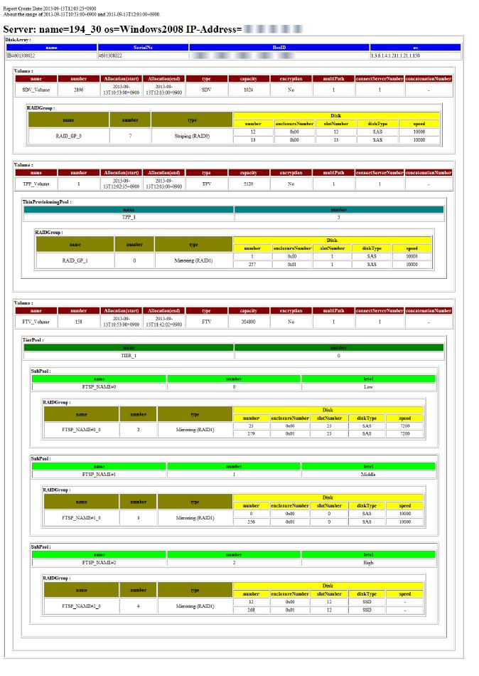
188
189 The character encoding of XML files is output in UTF-8 format. (On Windows, the destination directory privileges are inherited.) Target The report creation command creates a report file from the report information in the information stack file. For volumes that meet all of the following conditions, a report is created: - Data accumulated in the information stack file - Volume exited within the period specified by the report creation command The number of volumes connected to the servers registered to ETERNUS SF system is output into the report information. The unit price charged per target is determined by the center administrator. 8.2 Supported Device The devices for which the Reporting function is supported are as follows: ETERNUS DX S4 series ETERNUS DX S3 series Device ETERNUS DX S2 series (excluding DX60 S2) ETERNUS AF series ETERNUS DX200F Firmware Version All versions V10L40 or later All Versions 8.3 Operation Using the Reporting function center users can be charged according to his (her) usage. To use the Reporting function, preparation is required in accordance with the operational environment. This section describes specific uses of the Reporting function including design, setup, operation and maintenance to charge fees. The flow for creating an invoice is as follows:
190 1. Design Define charging method and report information retention period. 2. Setup The content of setup is as follows: - Register the ETERNUS SF Storage Cruiser Standard Edition license. - Set up a policy file based on the report information retention period. - Activate periodic command execution in Web Console so that report information can be collected and a report can be created, periodically. Refer to "Setup from Web Console" in " Setup Periodic Command Execution" for information on how to activate the Reporting function. - Create an accounting application. 3. Operation Make an invoice using an accounting application based on a monthly created report. 4. Backup/Restore Back up the information stack file periodically as required Design Define Charging Method For assistance in defining a charging method, the following example cases are provided. Based on the following requirements, do various settings of the Reporting function and create an accounting application:
191 - Range of charged servers - Charge a fee per server and send an invoice. - Charge a fee per group of multiple servers and send an invoice. - Unit of charged time - Charge a fee per hour. - Charge a fee on a daily basis. - How to calculate fees - Set a unit price per volume capacity to calculate fees based on allocation and usage period. - Set extra/reduced fees based on volume additional information. - When and for which period to make an invoice - Charge usage fee for the previous week at 3:00 AM every Monday. - Charge usage fee for the previous month on the 10 th of each month. - How to deliver the invoice to the center user - Send usage fee to the user by . - Print out the invoice to send to the user by post. - What to do if collecting charging information or making an invoice fails - Sound an alarm using the buzzer. - Send a notification to the center administrator Concept of Volume Allocation Period Concept of Volume Allocation Period Since the Reporting function calculates a volume allocation period from periodically collected information, the actual volume allocation period allocated by the center user is different from that recognized by the Reporting function. Basically, an allocation period for one volume is a period from when volume is connected to server to when volume is disconnected from server. However, if the configuration information for a volume connected to server has been changed, the volume is handled as a new volume. In this case, two volumes are output ("Volume configuration information is changed" indicates that any element other than the Header information written in "Table 8.2 Attributes Maintained by Elements" has been changed). The output on a per volume configuration basis makes it possible to charge fees in accordance with the volume configuration. The start/end date and time of using a volume allocation period recognized by the Reporting function is defined as follows: - Start date and time of use Date and time when the report information collection command was run after server connection or configuration information for volume connected to server has been changed. - End date and time of use Date and time when the report information collection command was run after server disconnection or volume configuration information has been changed. The following is an example of running the report information collection command per day:
192 The volume allocation period recognized by the Reporting function is as follows: - VOL1 0:00 of 1/2 to 0:00 of 1/4 (2 days in all) - VOL2 0:00 of 1/3 to 0:00 of 1/4, and 0:00 of 1/4 to 0:00 of 1/6 (3 days in all) Since in this example a collection interval is set to one day, a maximum of 23 hours and 59 minutes of error is caused. The relation between information collection interval and error is as shown in "Table 8.1 Influence Rate by Information Collection Interval and Collected Information Amount". Table 8.1 Influence Rate by Information Collection Interval and Collected Information Amount Information Collection Interval Accumulated Information Amount Time Lag Reflected in Report Information Long Little Large Short Large Small Concept of Volume Allocation within Report Output Period Report information is output in the report file based on the volume allocation period recognized by the Reporting function within a report output period. The point where the report output period specified by the user when creating a report overlaps the volume allocation period recognized by the Reporting function is a volume allocation period output into the report file
193 The volume allocation period recognized by the Reporting function is 4/8 to 4/22. In the following report output period, a volume allocation period output in the report file is as follows: No. Report Output Period Volume Allocation Period Output in Report File Remark 1) 4/1-4/7 None Report output period is out of volume allocation period. 2) 4/10-5/10 4/10-4/22-3) 4/1-5/1 4/8-4/ Define Report Information Retention Period The report creation command removes the old information exceeding the period preset by the policy from the information stack file. First, define how long to retain report information. A report information retention period is defined based on the following factors: - Possible restrictions from the purpose of use - Retention period by internal control - Backup interval of information stack file - Interval of creating a report - Interval of collecting information, etc. - Quotation of the information stack file capacity based on the configuration of an assumed storage system Refer to the ETERNUS SF Installation and Setup Guide for information on estimating the information stack file capacity. The defined retention period is enabled by being set in the policy file. See Refer to " Setup Policy" for information on how to set a retention period
194 Note The report information is deleted based on the retention period set in the policy file when the report creation command is run. For this reason, if the report creation command is not run even though the report information in the information stack file exceeds the retention period, the report information is not deleted Setup Obtain and Setup License To use the Reporting function, the ETERNUS SF Storage Cruiser Standard Edition license is required. For the ETERNUS Disk storage system to which the above license is not registered, reporting is not available. If the license is not registered for the ETERNUS Disk storage system and reporting is desired, register the license. Information The required license for ETERNUS Disk storage system is checked when the report information collection command is run. For this reason, even if the license is deleted while in use, already collected information is output in the report Setup Policy Specify the report information retention period in the information stack file by setting up a policy. See Refer to "A.11 policy.conf Parameter" for information on how to set up a policy Setup Periodic Command Execution Setup from Web Console Select Storage from Web Console to activate the Reporting function. Periodic command execution of the Reporting function can be started and stopped on a per storage basis. Enabling the Reporting function runs the report information collection command at the 5th minute of every hour and the report creation command at 6:30 AM on the 1st of every month periodically. The period of the report made by periodic command execution is one month from 0:00 of the 1st of the previous month to 0:00 of the 1st of the month. Set Up Periodic Command Execution by Creating Unique Application If you want to run the report creation command with more detailed settings than the command execution interval set up from Web Console, perform the following operations: - Use the operating system periodic execution function - Create an application to periodically invoke the report creation command Note For report period information specified for option of the report creation command, specify a proper value every time
195 Create Accounting Application A general charging method devised by the Reporting function is to charge usage fees for volumes used by servers within a report output period, which is calculated on a per server basis. Server administrator privileges are required to view the report file. The calculation formula for fees charged for volumes is as follows: Fees charged for volume = Unit price (a) * Volume allocation (b) * Volume allocation time (c) The following is an example of unit price per RAID level: RAID Level RAID0 RAID1 RAID1+0 RAID5 RAID6 RAID5+0 Unit Price per MB and per Hour 1 dollar 2 dollars 3 dollars 4 dollars 5 dollars 6 dollars Fees charged for server = Sum of fees charged per volume - The report file configuration output by the Reporting function is as follows: Server information ETERNUS Disk storage system information Allocated volume information Information for volume (disk type, RAID level, etc.) Allocated volume information... ETERNUS Disk storage system information... Server information... To calculate fees charged for volumes allocated per server, for example, create an accounting application to perform the following processing (element name in the brackets): foreach <server information (Servers)> { Fee charged for server = 0 foreach <ETERNUS Disk storage system information (DiskArrays)> { foreach <allocated volume information (Volumes)> { Obtain type of RAID group from RAID information (RAIDGroup). Get unit price from fee sheet according to obtained RAID group type.... a Obtain volume allocation (capacity) from volume information (Volume).... b Obtain volume allocation time (difference between end and start) from volume allocation information (Allocation).... c Fee charged for allocated volume = a * b * c Fee charged for server += Fee charged for allocated volume } } Output the fee charged for server } Example Calculate fees charged for server (charged for volume 1 and volume 2). The conditions per volume are as follows:
196 - Volume1 - RAID level: RAID0 (unit price: 1 dollar) - Volume allocation: 100 MB - Volume allocation period: 12/1 5:00-12/2 1:30 (20.5 hours in all) - Volume2 - RAID level: RAID6 (unit price: 5 dollars) - Volume allocation: 500 MB - Volume allocation period: 12/10 11:00-12/10 14:00 (3.0 hours in all) Fee charged per volume is as follows: - Fee charged for Volume1 1(dollar) * 100(MB) * 21(hour) = 2,100(dollars) - Fee charged for Volume2 5(dollars) * 500(MB) * 3(hour) = 7,500(dollars) Fee charged for server is as follows: - Fee charged for server 2,100(dollars) + 7,500(dollars) = 9,600(dollars) Operation Create Invoice The Reporting function outputs report information as a report. For the operation to charge fees mentioned in the later examples, the center administrator is responsible to do it. - Input a report file in the accounting application to make an invoice. (On completion of output of the report file, the accounting application loads the report file.) - Send an invoice to the center user. - Charge usage fee based on the invoice. Information The Reporting function calculates charging information based on volume capacity and usage period. Also, ETERNUS system obtains performance information for storage systems and switches as well as configuration information for storage systems. If you want to calculate charging information using performance information for each system, use the storageadm perfdata command to obtain the performance information Maintain Backup/Restore of Report Related Files For report related files (report information stack file, policy file, etc.) used in the Reporting function, it is recommended to back them up periodically, and restore them in an emergency so as to continue business. See Refer to " Backup of Manager" and " Restoring Manager" for the backup/restore procedure of report-related files
197 Error When Running Report Information Collection Command If an error occurs when running the report information collection command, the report information at that point in time is not stored in the information stack file. For example, if any error occurs on completion of information collection for Disk storage system A, the report information collection command terminates abnormally after the collected information for Disk storage system A has been deleted. If a force-quit is performed by [Ctrl] + [C] on the command side, the processing may be continued. In that case, check the Operation History of ETERNUS SF system. If any error is found in the report information collection command, correct the cause and then re-execute the command. If any error is found, the report information collection command notifies it in the following ways: - Command resetting value (The value of 1 or more is returned for abnormal end) - Command output message - ETERNUS SF system Operation History To set the report information collection command so that it is periodically run, it is necessary to read those values and make sure that no error is occurring. If any error should occur, a return code and message identifying the cause are returned, so that proper corrective action can be taken Error When Running Report Creation Command If an error occurs when running the report creation command, no report is created. If any error is found in the report creation command, correct the cause and then re-execute the command. If any error is found, the report creation command notifies it in the following ways: - Command return code (The value of 1 or more is returned for abnormal end) - Command output message - ETERNUS SF system Operation History To set the report creation command so that it is periodically run, it is necessary monitor the results and make sure that no errors are occurring. If any error should occur, a return code and message identifying the cause are returned, so that proper corrective action can be taken. If the ETERNUS SF Manager is stopped while the esfadm report create command (report creation command) is executing, re-executing the esfadm report create command after that may cause the command to terminate with an error. In this case, recover the environment with the following procedure: 1. Login to the Management Server with the following administrative permissions. - For Windows User belonging to the Administrators group - For Solaris/Linux "root" or user belonging to the root group 2. Move to the following directory. - For Windows $INS_DIR\Common\var\report ($INS_DIR means "Program Directory" specified at the ETERNUS SF Manager installation.) - For Solaris/Linux /var/opt/fjsvesfcm/var/report 3. Delete the retension_period file. 8.4 Configuration of Report File Output Overview The output configuration of a XML report is as follows:
198
199 Output Detail The following is the information on a per volume type basis: - For Standard Volume, SDV, WSV <Volume name="sdv_volume" number="2896" type="sdv" capacity="1024" encryption="no" multipath="1" connectservernumber="1" concatenationnumber="-"> <Allocation start=" t10:53: " end=" t12:03: " /> <RAIDGroups> <RAIDGroup name="raid_gp_0" number="7" type="striping (RAID0)"> <Disks> <Disk number="12" enclosurenumber="0x00" slotnumber="12" disktype="sas" speed="10000" /> <Disk number="13" enclosurenumber="0x00" slotnumber="13" disktype="sas" speed="10000" /> </Disks> </RAIDGroup> </RAIDGroups> </Volume> - For TPV <Volume name="tpp_volume" number="1" type="tpv" capacity="5120" encryption="no" multipath="1" connectservernumber="1" concatenationnumber="-"> <Allocation start=" t12:02: " end=" t12:03: " /> <ThinProvisioningPool name="tpp_1" number="3"> <RAIDGroups> <RAIDGroup name="raid_gp_1" number="0" type="mirroring (RAID1)"> <Disks> <Disk number="1" enclosurenumber="0x00" slotnumber="1" disktype="sas" speed="10000" /> <Disk number="257" enclosurenumber="0x01" slotnumber="1" disktype="sas" speed="10000" /> </Disks> </RAIDGroup> </RAIDGroups> </ThinProvisioningPool> </Volume>
200 - For FTV <Volume name="ftv_volume" number="158" type="ftv" capacity="204800" encryption="no" multipath="1" connectservernumber="1" concatenationnumber="-"> <Allocation start=" t10:53: " end=" t11:42: " /> <TierPool name="tier_1" number="0"> <SubPools> <SubPool name="ftsp_name#0" number="0" level="low"> <RAIDGroups> <RAIDGroup name="ftsp_name#0_0" number="2" type="mirroring (RAID1)"> <Disks> <Disk number="23" enclosurenumber="0x00" slotnumber="23" disktype="sas" speed="7200" / > <Disk number="279" enclosurenumber="0x01" slotnumber="23" disktype="sas" speed="7200" /> </Disks> </RAIDGroup> </RAIDGroups> </SubPool> <SubPool name="ftsp_name#1" number="1" level="middle"> <RAIDGroups> <RAIDGroup name="ftsp_name#1_0" number="3" type="mirroring (RAID1)"> <Disks> <Disk number="0" enclosurenumber="0x00" slotnumber="0" disktype="sas" speed="10000" /> <Disk number="256" enclosurenumber="0x01" slotnumber="0" disktype="sas" speed="10000" /> </Disks> </RAIDGroup> </RAIDGroups> </SubPool> <SubPool name="ftsp_name#2" number="2" level="high"> <RAIDGroups> <RAIDGroup name="ftsp_name#2_0" number="4" type="mirroring (RAID1)"> <Disks> <Disk number="12" enclosurenumber="0x00" slotnumber="12" disktype="ssd" speed="-" /> <Disk number="268" enclosurenumber="0x01" slotnumber="12" disktype="ssd" speed="-" /> </Disks> </RAIDGroup> </RAIDGroups> </SubPool> </SubPools> </TierPool> </Volume> The attributes maintained by elements are as shown in "Table 8.2 Attributes Maintained by Elements". Table 8.2 Attributes Maintained by Elements Element Name Description (Data Size) Output Difference per Volume Type Attribute Name FTV TPV Other Frequen cy Header Information to differentiate report A A A 1 created reportbegin reportend Date and time when report was created (string, 24 bytes) (*1) Start date and time of reporting period specified by esfadm report create command (string, 24 bytes) (*1) End date and time of reporting period specified by esfadm report create command (string, 24 bytes) (*1) A A A 1 A A A 1 A A A 1 version Report format version information (string, max 8 bytes) A A A
201 Element Name Description (Data Size) Output Difference per Volume Type Attribute Name FTV TPV Other Frequen cy Servers Maintain all Server elements. (All Server elements are sub-elements of this element) A A A 1 Server Number of servers connected to volumes A A A 1 or more name Server name (string, max. 255 bytes) A A A 1 os Operating system type (string, max. 255 bytes) A A A 1 ipaddress IP address (string, max. 64 bytes) A A A 1 DiskArrays DiskArray Maintain all DiskArray elements related to servers (All DiskArray elements are sub-elements of this element) Disk array information including volumes connected to servers A A A 1 A A A 1 or more name Disk array name (string, max. 255 bytes) A A A 1 serialno Serial number (string, max. 16 bytes) A A A 1 boxid Box ID (string, 40 bytes) A A A 1 ec Enterprise code (string, max. 255 bytes) A A A 1 Volumes Maintain Volume elements related to some DiskArray, connected to server (All Volume elements are sub-elements of this element) A A A 1 Volume Information for volume connected to server A A A 1 or more name Volume name (string, max. 16 bytes) A A A 1 number Volume number (value: decimal, max. 10 bytes) A A A 1 type capacity encryption multipath Volume type (string, max. 16 bytes) Standard, WSV, SDV, TPV or FTV Volume capacity (MB) (value: decimal, max. 10 bytes) The meaning varies with volume type. Standard/WSV: Physical capacity SDV/TPV/FTV: Logical capacity Encryption status (string, max. 255 bytes) Yes: Enable No: Disable Number of paths between server and volume (value: decimal, max. 10 bytes) A A A 1 A A A 1 A A A 1 A A A 1 connectservernumber Number of connected servers (value: decimal, max. 10 bytes) A A A 1 concatenationnumber Number of concatenated LUNs in volume (string, max. 255 bytes) If LUN is not concatenated, a hyphen ("-") is displayed. A A A 1 Allocation Information for volume allocation A A A 1 start end Start date and time of volume allocation (string, 24 bytes) (*1) End date and time of volume allocation (string, 24 bytes) (*1) A A A 1 A A A
202 Element Name Description (Data Size) Output Difference per Volume Type Attribute Name FTV TPV Other Frequen cy TierPool Tier pool information A N/A N/A 1 or more name Tier pool name (string, max. 64 bytes) A N/A N/A 1 number Tier pool number (value: decimal, max. 10 bytes) A N/A N/A 1 SubPools Maintain sub-pool elements (All sub-pool elements are sub-elements of this element) A N/A N/A 1 SubPool Sub-pool information A N/A N/A 1 or more name Sub-pool name (string, max. 64 bytes) A N/A N/A 1 number Sub-pool number (value: decimal, max. 10 bytes) A N/A N/A 1 level Layer level (string, max. 32 bytes) Low: Low sub-pool Middle: Middle sub-pool High: High sub-pool For one layer Tier pool, a hyphen ("-") is displayed. A N/A N/A 1 ThinProvisioningPool Thin Provisioning Pool information N/A A N/A 1 or more name Thin Provisioning Pool name (string, max. 16 bytes) N/A A N/A 1 number Thin Provisioning Pool number (value: decimal, max. 10 bytes) N/A A N/A 1 RAIDGroups Maintain RAID Group elements (All RAID Group elements are sub-elements of this element) A A A 1 or more RAIDGroup RAID information A A A 1 or more name RAID Group name (string, max. 16 bytes) A A A 1 number RAID Group number (value: decimal, max. 10 bytes) A A A 1 Disks type RAID Group type (string, max. 64 bytes) - Striping (RAID0) - Mirroring (RAID1) - High Performance (RAID1+0) - High Capacity (RAID5) - High Reliability (RAID6) - High Reliability (RAID6-FR) - Reliability (RAID5+0) - Unknown Maintain Disk elements (All Disk elements are sub-elements of this element) A A A 1 A A A 1 Disk Disk information A A A 1 or more number Disk number (value: decimal, max 10 bytes) A A A
203 Element Name Description (Data Size) Output Difference per Volume Type Attribute Name FTV TPV Other Frequen cy enclosurenumber Enclosure number (value: hexadecimal, 4 bytes) For disks contained in Controller Enclosure, "0x00" is displayed. A A A 1 slotnumber Slot number (value: decimal, max. 10 bytes) A A A 1 disktype speed Disk type (string, max. 255 bytes) SAS, SSD or SED-SAS Disk rotation count (rpm) (value: decimal, max. 10 bytes) If there is no rotation count, a hyphen ("-") is displayed. A A A 1 A A A 1 "A" indicates "Applicable", and "N/A" indicates "Not Applicable". *1: For date and time, the local time of ETERNUS SF system is output in ISO8601 format

204 Chapter 9 Storage Cluster Function In the Storage Cluster function, storage used as an active system is referred to as "Primary Storage" and storage used as a standby system is referred to as "Secondary Storage". Note There are limitations to the operating system and driver of business server to support transparent failover of Storage Cluster. For details, contact Fujitsu Technical Support. 9.1 Overview Storage Cluster function switches over to the components in a standby system from the components in an active system transparently from external environments. In the existing operation, data must be kept equivalency maintenance state in an environment in which REC Paths are configured between the Primary Storage and the Secondary Storage, and if the Primary Storage stops, failover to the Secondary Storage must be performed in the following steps: 1. Change physical connections to the Secondary Storage and zoning configuration. 2. Re-acknowledge volumes by restarting business server. Using the Storage Cluster function can save the time and steps spent in this work and realize transparent failover. System Structure The following is a description of basic system structure required to use the Storage Cluster function. The example of system structure is shown in "Figure 9.1 Storage Cluster Function: Example of System Structure". Figure 9.1 Storage Cluster Function: Example of System Structure
205 Item Description Primary Storage Secondary Storage Storage Cluster Controller Storage used as an active system. Storage used as a standby system. Server that monitors the Primary Storage and the Secondary Storage. When using Automatic Failover, Storage Cluster Controller must be required. Configure the Storage Cluster function on the Management Server. Connect the Management Server to the Primary Storage and the Secondary Storage with the management LAN. In addition, to use Automatic Failover, connect the Storage Cluster Controller to the Primary Storage and the Secondary Storage with the management LAN. See Refer to "Automatic Failover" for details of Automatic Failover. Point - If the Automatic Failover function is not used, Storage Cluster Controller is not required. - Data is copied between the Primary Storage and the Secondary Storage with REC Path. 9.2 Operation Overview This section describes the following operations and concepts required for the Storage Cluster function: - TFOV - REC Path - Failover Mode - Failback Mode - Split Mode - TFO Group - Pairing of CA Ports - Automatic Failover - Automatic Failback - Releasing and Recovering TFO Pairs - Deconstruction of Storage Cluster Environment - Control of Link Status of Primary/Secondary Storage CA Ports - Storage Cluster Controller TFOV TFOV is a volume for which failover is enabled. Among TFOVs created on both the Primary Storage and the Secondary Storage, those TFOVs that have the same Host Logical Unit (HLU) number and capacity are volumes whose data is synchronized. In addition to data synchronization, the volume information on the
206 Secondary Storage is changed as shown in "Table 9.1 Change in Volume Information on Pre- and Post-Data Synchronization Secondary Storage". Table 9.1 Change in Volume Information on Pre- and Post-Data Synchronization Secondary Storage Volume Information to be Changed Pre-Data Synchronization Post-Data Synchronization UID UID unique to volume on the Secondary Storage. UID of volume on the Primary Storage of a pair. Product ID Product ID unique to the Secondary Storage. Product ID of the Primary Storage of a pair. Note - Even if a volume on the Secondary Storage is removed from the synchronized volume by the operation of deleting the TFO group after data has been synchronized, post-data synchronization volume information is inherited. For this reason, when continuing to use the volume on the Secondary Storage, use the ETERNUS CLI to return the volume information to pre-data synchronization status. Refer to the ETERNUS Disk storage system manuals for the command name and the format of ETERNUS CLI used. - There is an upper limit for the total capacity of all TFOVs per storage device. Refer to "Expanding Total Capacity of TFOVs" for the procedure to expand the total capacity of TFOVs per storage device. Point The capacity of a TFOV can be expanded. Refer to " Expanding Business Volume Capacity" for details. REC Path TFOV data is transferred in synchronization mode using the REC path. An ETERNUS Disk storage system manages copy sessions used in the Storage Cluster function and Advanced Copy sessions separately. Since the ETERNUS Disk storage system automatically controls copy sessions used in the Storage Cluster function, it is not required to configure copy sessions and copy groups in this product. Point When an REC route temporary fault (communication break) occurs, a differential copy is executed after the REC route recovers, and the data is automatically recovered in the equivalent state. As failover does not occur during the period until the REC route is recovered, we recommend a redundant REC route configuration. Failover Mode This mode is related to the failover method from the Primary Storage to the Secondary Storage. Either of the following can be selected. Mode Auto (default) Manual Explanation This is the Failover mode that runs automatically when a failure of the Primary Storage is detected. Business can be continued without stopping. A Storage Cluster controller is required when operated in this mode. When this mode is set, failover can be performed manually from Web Console. This is the Failover mode that runs manually. A Storage Cluster controller is not required when operated in this mode

207 Note Even if the interface type of the REC path is "iscsi", if the Primary Storage and the Secondary Storage do not support Automatic Failover through the REC path of the iscsi port, set this mode to "Manual". Failback Mode This mode is related to the failback method from the Secondary Storage to the Primary Storage. Either of the following can be specified. Mode Explanation Auto Manual (default) This is the Failover mode that runs automatically when a failure recovery of the Primary storage is detected. This is the Failback mode that runs manually. Failback can be performed at any time from Web Console. Split Mode Split Mode specifies for volumes in the Primary Storage whose REC Path is disconnected whether to give priority to business continuity and continue Write or to assure the equivalent state of data on the Primary Storage and the Secondary Storage. Either of the following is specified: - "Read/Write"(default) Give priority to business continuity and continue writing data to volumes in the Primary Storage. In this case, data is written only on the volumes in the Primary Storage, causing the data to be nonequivalent to data in the Secondary Storage. - "Read" Give priority to maintenance of data equivalent state and inhibit writing data to the volumes in the Primary Storage. TFO Group TFO Group is a motion unit of failover on one device and a group for which the connection configuration, policy, status and maintenance required to perform failover is consolidated. TFO Group includes one or more CA ports and volumes allowed to access those CA ports. The example of TFO Group is shown in "Figure 9.2 Example of TFO Group". Figure 9.2 Example of TFO Group TFO Group has the following status. The TFO status changes with execution of failover or failback:

208 Point The input conditions for the TFO Group name are as follows: - The 1-16 characters which are alphanumeric characters "A-Z, a-z, 0-9" and special characters. However, ",? " ' \ * %" cannot be used. Table 9.2 TFO Status TFO Status Active Standby Meaning Indicates an active side. Accessible from Management Server. Indicates a standby side. Inaccessible from Management Server. If default TFO status is Active in creating an environment, the TFO Group is called "Primary TFO Group" and if Standby, "Secondary TFO Group". Pairing of CA Ports The Storage Cluster function shares the port parameter in the CA ports of two ETERNUS Disk storage systems, controls the Link status of each CA port, and achieves the failover. The CA ports included in one TFO Group shares one port parameter with the CA ports included in the other TFO Group between storage systems. This sharing operation is referred to as "Pairing of CA ports". Also, a pair of CA ports sharing port parameter is referred to as "CA port pair". For FC configurations, WWPN/WWNN is shared. By pairing CA ports, WWPN/WWNN of the CA port in the Primary Storage is automatically configured as a logical WWPN/WWNN to the CA port in the Secondary Storage and the CA port in the Secondary Storage is Linkdown. For iscsi configurations, iscsi name and iscsi IP address are shared. By pairing CA ports, the CA port in the Secondary Storage is Linkdown. After that, by setting the iscsi name and iscsi IP address of the CA port in the Primary Storage to the CA port in the Secondary Storage manually, the iscsi name and iscsi IP address can be shared. The image of CA port pair is shown in "Figure 9.3 Example of CA Port Pair". Figure 9.3 Example of CA Port Pair Automatic Failover Automatic Failover is a function that makes the Secondary TFO Group active automatically when any failure is detected in an ETERNUS Disk storage system in which the Primary TFO Group exists. To perform Automatic Failover, Storage Cluster Controller connected with management LAN is required
\" shows an image that Storage A (Primary Storage) is down and a failover to Storage B (Secondary Storage) is")
209 "Figure 9.4 Behavior of Automatic Failover When Storage Device Is Downed (for FC Configuration)" shows an image that Storage A (Primary Storage) is down and a failover to Storage B (Secondary Storage) is performed when Storage A and Storage B are in use. "Figure 9.5 Behavior of Automatic Failover When CA Port Is Linked Down (for FC Configuration)" shows an image that all the CA ports belonging to the Primary TFO Group are linked down because of CA port failure or connection failure in Storage A (Primary Storage) and a failover to Storage B (Secondary Storage) is performed when Storage A and Storage B are in use. These are examples for FC configurations. For iscsi configurations, the iscsi name and iscsi IP address are set for the CA port and the switch becomes the network switch. Figure 9.4 Behavior of Automatic Failover When Storage Device Is Downed (for FC Configuration)
 In accordance with link switchover of each CA port, the status of TFO Group is also automatically switched, so that")
210 Figure 9.5 Behavior of Automatic Failover When CA Port Is Linked Down (for FC Configuration) In accordance with link switchover of each CA port, the status of TFO Group is also automatically switched, so that the volumes in the Secondary TFO Group become accessible. Automatic Failback Automatic Failback is a function in which the Primary TFO Group automatically becomes "Active" when recovering from the failure of ETERNUS Disk storage system with the Primary TFO Group detected
211 Releasing and Recovering TFO Pairs These operations are performed during a maintenance procedure when a RAID failure, a RAID close, or a bad sector occurs. Select a target pair from the list of volume pairs for which Storage Cluster is available. Point - When releasing TFO pairs Release the TFO pairs of all TFOVs that belong to the failed RAID group so that the RAID group can be maintained. - When recovering TFO pairs Recover the TFO pairs of all TFOVs that belong to the failed RAID group. By recovering the TFO pairs, a synchronization between the paired volumes are performed with the initial copy. Refer to "Table 9.6 Time Required for Initial Copy (Standard Value of 1 TB Physical Capacity Volume)" for the time required for an initial copy. Deconstruction of Storage Cluster Environment If such a trouble as requires device replacement occurs and an ETERNUS Disk storage system should be replaced, deconstruct the Storage Cluster environment. Delete TFO Groups to deconstruct the Storage Cluster environment. For FC configurations, when deleting TFO Groups, you can select either of the following actions to handle WWPN/WWNN of the CA port for the Secondary Storage: a. Return the Secondary Storage CA port to its original WWPN/WWNN. b. Return the Secondary Storage CA port not to its original WWPN/WWNN but continue to use the logical WWPN/WWNN. If step "a" is selected, it does not compete with the WWPN/WWNN of the Primary Storage CA port. If step "b" is selected, the device operated as the Primary Storage can be replaced while the Secondary Storage is accessible from the Management Server. Note - For FC configurations If both the Primary Storage CA port and the Secondary Storage CA port get active, their WWPN/WWNN competes with each other, possibly causing data corruption. Therefore, when selecting step "b", keep the following rules: - Do not delete the TFO Group before making sure that the Primary Storage CA port is physically disconnected from SAN. - Do not connect to SAN the ETERNUS Disk storage system that had the Primary TFO Group deleted. - For iscsi configurations The set values for the iscsi name and the iscsi IP address remain unchanged. Therefore, keep the following rules: - Check whether the iscsi IP address is not a duplicate in the same SAN. If it is a duplicate, do not delete the TFO group before changing the iscsi IP address. - Do not delete the TFO Group before making sure that the storage device in the standby side is physically disconnected from SAN. Control of Link Status of Primary/Secondary Storage CA Ports Depending on pairing of CA ports and failover, the port parameter and Link status of CA ports are changed. The device whose Link status is Linkup is accessible from the Management Server. For FC configurations, the value of WWPN/WWNN is changed by pairing CA ports. For iscsi configurations, manually setting the parameter of the iscsi CA port of the Secondary Storage to match that of the Primary Storage after a CA port pairing can control the Link status
212 Change in Link status of each CA port with CA port pairing and failover/failback operations are shown in "Table 9.3 Change in Link Status of CA Port (for FC Configurations)" and "Table 9.4 Change in Link Status of CA Port (for iscsi Configurations)". Table 9.3 Change in Link Status of CA Port (for FC Configurations) Primary Storage Secondary Storage Timing WWPN/WWNN Link Status Link Status WWPN/WWNN Linkup Pre-CA port pairing Linkup WWPN/WWNN of Secondary Storage side Post-CA port pairing Primary Storage stops Linkdown Under failover WWPN/WWNN of the Primary Storage side Linkdown Failover completed Primary Storage recovered Linkup WWPN/WWNN of the Primary Storage side Failback started Under failback Failback completed Linkdown Linkup Storage Cluster deconstructed (*1) Linkup WWPN/WWNN of the Secondary Storage side *1: When returning the WWPN/WWNN of the Secondary Storage CA port to its original status. Table 9.4 Change in Link Status of CA Port (for iscsi Configurations) Primary Storage Secondary Storage Timing iscsi Information Link Status Link Status iscsi Information Linkup Pre-CA port pairing Linkup iscsi information of the Post-CA port pairing Secondary Storage side Parameter setting of iscsi CA port of the Secondary Storage side Primary Storage stops Linkdown Under failover iscsi information of the Primary Storage side Linkdown Failover completed Primary Storage recovered Linkup iscsi information of the Primary Storage side Failback started Under failback Linkup Failback completed Parameter setting of iscsi CA port of the Secondary Storage side Storage Cluster deconstructed Linkdown Linkup iscsi information of the Secondary Storage side Storage Cluster Controller To perform Automatic Failover, Storage Cluster Controller connected with management LAN is required. Two ETERNUS Disk storage systems use a REC Path for checking the living confirmation. If the REC Path is disconnected, even if the two ETERNUS Disk storage systems are running, failover may be performed by false recognition. To prevent this false recognition, install Storage Cluster Controller to communicate with both Primary and Secondary ETERNUS Disk storage systems with management LAN
213 The example of structure between Primary and Secondary ETERNUS Disk storage systems and Storage Cluster Controller is shown in "Figure 9.6 Structure Example of Life Check via Storage Cluster Controller". In this structure example, communication status, device status and timing of Automatic Failover are shown in "Table 9.5 Timing of Automatic Failover Operation". Figure 9.6 Structure Example of Life Check via Storage Cluster Controller Table 9.5 Timing of Automatic Failover Operation Number Communication Status (1) (2) (3) Primary Storage Secondary Storage 1 Y Y Y Device Status Timing of Automatic Failover Operation and Status Change 2 N Y Y 3 Y N Y 4 Y Y N Alive Alive N/A 5 N N Y Down 6 N Y N Down Alive 7 Y N N Alive A Primary Storage: Active -> Standby Secondary Storage: Standby -> Active N/A 8 N N N Down Down N/A (all blocked) (*1) Y: Communication enabled status N: Communication disabled status *1: During a disaster, when recreating a network environment that includes communication of Storage Cluster Controller, the communication from Storage Cluster Controller may be temporarily disconnected and an overall blockage may occur. Note Automatic Failover does not operate in the following cases: - For FC configurations - When "route (1) between the Primary Storage and the Secondary Storage" failed 10 seconds after "route (2) between the Primary Storage and the Storage Cluster controller" had failed. - When "route (2) between the Primary Storage and the Storage Cluster controller" failed three seconds after "route (1) between the Primary Storage and the Secondary Storage" had failed
 between the Primary Storage and the Storage Cluster controller\" failed seven seconds after \"route (1) between the Primary Storage and the Secondary Storage\" had failed.")
214 - For iscsi configurations - When "route (1) between the Primary Storage and the Secondary Storage" failed 20 seconds after "route (2) between the Primary Storage and the Storage Cluster controller" had failed. - When "route (2) between the Primary Storage and the Storage Cluster controller" failed seven seconds after "route (1) between the Primary Storage and the Secondary Storage" had failed. Location of Storage Cluster Controller Storage Cluster Controller and each monitored ETERNUS Disk storage system monitor each other. Therefore, if the Storage Cluster Controller and the managed ETERNUS Disk storage systems are placed in the same building, the following trouble could occur: - If the building is exposed to disaster, all the paths are blocked and failover gets disabled. To prevent the above trouble, it is recommended to place the Storage Cluster Controller and each monitored ETERNUS Disk storage system in separate buildings respectively. The location example is shown in "Figure 9.7 Location Example of Storage Cluster Controller and Monitored ETERNUS Disk Storage Systems". Also, the Storage Cluster Controller can be located on the same server as Management Server. Figure 9.7 Location Example of Storage Cluster Controller and Monitored ETERNUS Disk Storage Systems 9.3 Work Flow The following is a description of the procedure to create a Storage Cluster environment. Refer to "9.4 Operation Method" for details of each procedure

215 When Registering New Primary and Secondary Storage Devices Figure 9.8 Operation Procedure When FC Ports Are Used

216 Figure 9.9 Operation Procedure When iscsi Ports Are Used

217 When Adding Secondary Storage Where Only Primary Storage Is Used Figure 9.10 Operation Procedure When FC Ports Were Used

218 Figure 9.11 Operation Procedure When iscsi Ports Were Used

219 When Adding Volume Figure 9.12 Operation Procedure When Volumes Are Added 9.4 Operation Method This chapter describes how to use the Storage Cluster function Installation Preconfigure in the following steps to use the Storage Cluster function: 1. Registering ETERNUS Disk Storage Systems and License 2. Registering and Configuring Server and FC Switch 3. Configuring Storage Cluster Structure 4. Expanding Total Capacity of TFOVs Registering ETERNUS Disk Storage Systems and License 1. Register ETERNUS Disk storage system Register all the ETERNUS Disk storage systems that use the Storage Cluster function. See Refer to "Register ETERNUS Disk Storage System" in the ETERNUS SF Web Console Guide for the procedure to register ETERNUS Disk storage systems. 2. Register license Register Storage Cluster Option License to the ETERNUS Disk storage systems registered in the above step 1. This license must be registered to all the ETERNUS Disk storage systems that use the Storage Cluster function. Information To register Storage Cluster Option License, the following licenses must be registered: - ETERNUS SF Storage Cruiser Standard Edition License - ETERNUS SF AdvancedCopy Manager Remote Copy License
220 See Refer to "Register License" in the ETERNUS SF Web Console Guide for the procedure to register licenses. Registering and Configuring Server and FC Switch 1. Register FC switch (for FC configurations only) Register all the FC switches that use the Storage Cluster function to devices. See Refer to "Register FC Switch" in the ETERNUS SF Web Console Guide for the procedure to register FC switches. 2. Configure Storage Cluster Controller When using Automatic Failover, Storage Cluster Controller must be configured. Log in not to Web Console but to the server to configure the Storage Cluster Controller and check its settings. See Refer to "9.5 Storage Cluster Controller" for the procedure to configure the Storage Cluster Controller. 3. Register business server Register all the business servers used for the Storage Cluster function. See Refer to "Register Server" in the ETERNUS SF Web Console Guide for the procedure to register business servers. Configuring Storage Cluster Structure Configure the structure of ETERNUS Disk storage systems required for the Storage Cluster function. The structure example is shown in "Figure 9.13 Structure Example of Storage Cluster (When Primary ETERNUS Disk Storage System is Active)"
 The following settings are required: - Configuring Port - Port for REC path - Port for connecting to")
221 Figure 9.13 Structure Example of Storage Cluster (When Primary ETERNUS Disk Storage System is Active) The following settings are required: - Configuring Port - Port for REC path - Port for connecting to business server - Configuring REC Path - Configuring TFO Group The setting procedure for FC configurations differs from that for iscsi configurations. The setting procedure for each configuration is as follows: - For FC configurations 1. Configuring Port (port for REC path) 2. Configuring Port (port for connecting to business server) 3. Configuring REC Path 4. Configuring TFO Group - For iscsi configurations 1. Configuring Port (port for REC path) 2. Configuring REC Path 3. Configuring TFO Group 4. Configuring Port (port for connecting to business server)
222 Note For iscsi configurations, if step 4 "Configuring Port (Port for Connecting to Business Server)" is performed before step 3 "Configuring TFO Group", the business server may be prevented from accessing the Primary Storage and the Secondary Storage due to conflicts occurring with the IP addresses. Do not mistake FC configurations for iscsi configurations. The setting method for each configuration is as follows. Configuring Port The Storage Cluster function uses the ports on ETERNUS Disk storage systems for the following two purposes: - Port for REC Path - Port for Connecting to Business Server Port for REC Path The Storage Cluster function uses the synchronous transfer method to keep data equivalent between business volumes on the Primary Storage and the Secondary Storage. To configure REC Paths that become their copy pathways are required ports on Primary and Secondary ETERNUS Disk storage systems. There are requirements for ports used to configure REC Paths in the Storage Cluster function as follows: - Port interface type must be "FC" or "iscsi". "FCoE" is not supported. - Port mode must be "RA" or "CA/RA". As required, change the port mode for each ETERNUS Disk storage system. See Refer to "Change FC/iSCSI/SAS Port Settings" in the ETERNUS SF Web Console Guide for the procedure to change Port mode. Port for Connecting to Business Server The Storage Cluster function makes a pair of ports through which to access business servers between Primary and Secondary ETERNUS Disk storage systems. Automatically switching a port to be accessed at the time of failover/failback can continue to access business volumes. There are requirements for ports through which to access business servers as follows: - Port interface type must be "FC" or "iscsi". "FCoE" is not supported. - Port mode must be "CA", however "CA/RA" is not supported. - Port parameters specified for paired ports must be the same. However, for iscsi configurations and when using the Primary Storage and the Secondary Storage between different subnets, different iscsi IP addresses can be specified for the Primary Storage and the Secondary Storage. - CA port pairs that are created between the Primary Storage and the Secondary Storage must have the same interface type. - When creating multiple CA port pairs, the interface type must be the same. - When creating two or more TFO groups in one ETERNUS Disk storage system, the CA port pairs of each TFO group must have the same interface type. - When creating multipath connection, the same number of ports should be provided to Primary and Secondary ETERNUS Disk storage systems respectively so as to make a pair of all the associated ports. There should be two or more ports. As required, change Port mode and Port parameter for respective ETERNUS Disk storage systems
223 See Refer to "Change FC/iSCSI/SAS Port Settings" in the ETERNUS SF Web Console Guide for the procedure to change Port mode and Port parameter. Configuring REC Path Use the ports configured in "Port for REC Path" to configure a REC Path between Primary and Secondary ETERNUS Disk storage systems. Once a REC Path is configured from either the Primary ETERNUS Disk storage system or the Secondary ETERNUS Disk storage system, it is set to both ETERNUS Disk storage systems. Use the following steps on Web Console to configure a REC Path: 1. Click Storage on the global navigation tab. Registered ETERNUS Disk storage systems are displayed on the Main pane. 2. On the Main pane, click the Name of a target ETERNUS Disk storage system. 3. On the Category pane, click Storage Cluster. The items on the Category pane switch to those associated with Storage Cluster function. 4. On the Category pane, click REC Path. Created REC Paths are displayed on the Main pane. 5. On the Action pane, click Remote Copy Setting under Wizard. The Remote Advanced Copy Setting Wizard screen is displayed, and click Next. The screen on which to select a remote partner is displayed. 6. Select an ETERNUS Disk storage system to be remote copy destination, and click Next. The screen on which to set a copy table size is displayed. 7. Set copy parameters for both ETERNUS Disk storage systems as copy source and copy destination, and click Next. The screen on which to configure REC Paths is displayed. 8. Select Remote copy path and Connectivity type between ETERNUS Disk storage systems and click Next. The screen on which to configure REC buffer is displayed. 9. Since REC buffer is not needed to use the Storage Cluster function, click Next. The Setting Confirmation screen is displayed. 10. If the information is correct, click Close. Note The settings of REC Path line speed and compression ratio are valid only when one or more REC Paths are added. If only existing REC Paths are deleted, specified line speed and compression ratio are not set. Configuring TFO Group Use the ports for connecting to the business server to configure TFO Groups between Primary and Secondary ETERNUS Disk storage systems. Once TFO Groups are configured from either the Primary ETERNUS Disk storage system or the Secondary ETERNUS Disk storage system, they are configured on both ETERNUS Disk storage systems. Point For the ETERNUS Disk storage systems whose firmware version number is V10L70 or later, when creating a TFO group, Automatic Failover is set to work if CA port linkdown occurs. Not to make Automatic Failover work even if CA port linkdown occurs, it is required to change the TFO group configuration using ETERNUS CLI. Refer to the ETERNUS Disk storage system manuals for the command name and the format of ETERNUS CLI used. Also, to use Automatic Failover for CA port linkdown in a TFO group, the TFO group must satisfy all the following conditions: - The Failover mode is "Auto"
224 - The Failback mode is "Manual". Note - To use the Automatic Failover mode, Storage Cluster Controller is required. Refer to "9.5 Storage Cluster Controller" for the procedure to configure the Storage Cluster Controller and confirm its settings. - If a number of TFO Groups are created in a pair of ETERNUS Disk storage systems, one pair of CA ports cannot be specified for multiple TFO Groups. - When using the Storage Cluster function in both directions as shown in "Figure 9.14 Structure Example of Using Storage Cluster Function Bi-Directionally", two TFO groups must be created where the Primary Storage is switched with the Secondary Storage for a pair of ETERNUS Disk storage systems. Figure 9.14 Structure Example of Using Storage Cluster Function Bi-Directionally - In multipath connection, a number of access paths (Host Affinity) may be configured for a certain LUN/Affinity group. When specifying the ports included in such access paths (Host Affinity) for a CA port pair in a TFO Group, select all the ports associated with the target LUN/Affinity group at the same time. - Configure access paths (Host Affinity) for CA ports on the Secondary Storage after having configured TFO Groups. If access paths (Host Affinity) are configured for CA ports on the Secondary Storage before configuring TFO Groups, at that point the volumes in the Secondary Storage are recognized by business server, possibly causing a trouble. For this reason, on the port pair selection screen, a CA port on the Secondary Storage on which the access path (host affinity) has been set cannot be selected. - When adding a CA port for the TFO Group, it is necessary for the Primary Storage TFO status to be "Active" and the Secondary Storage TFO status to be "Standby"
225 - When a TFO Group is created on the ETERNUS Disk storage system whose firmware version is earlier than V10L70, even if the firmware version is upgraded to V10L70 or later, the TFO Group is set not to use the Automatic Failover function triggered by CA port linkdown. To use the Automatic Failover function triggered by CA port linkdown for the TFO Group, it is required to change TFO group settings with ETERNUS CLI. Refer to the ETERNUS Disk storage system manuals for the command name and the format of ETERNUS CLI used. Use the following steps on Web Console to configure TFO Groups: 1. Click Storage on the global navigation tab. Registered ETERNUS Disk storage systems are displayed on the Main pane. 2. On the Main pane, click the Name of a target ETERNUS Disk storage system. 3. On the Category pane, click Storage Cluster. Created TFO Groups are displayed on the Main pane. 4. On the Action pane, click Set under TFO Group. The TFO Group Configuration Wizard screen is displayed. 5. The Selection screen for ETERNUS Disk storage systems and options is displayed. - When creating a new TFO Group: Select a remote ETERNUS Disk storage system and specify which ETERNUS Disk storage system to be the Primary Storage. - When changing an existing TFO Group: Specified Primary and Secondary Storages cannot be changed. As for an initial value of the Failover mode, "Auto" has been selected. Select "Manual" when you do the failover by manual operation. As for an initial value of the Failback mode, "Manual" has been selected. Select "Auto" when you do the failback by automatic operation. On completion of input, click Next. The TFO Group Configuration screen is displayed. 6. Select from a list of ports for the Primary Storage and the Secondary Storage, one port for each storage to be paired and click Add. When deleting, select an unnecessary pair from the Port Pair List table to click Delete. 7. On completion of required configuration, click Next. The Setting Confirmation screen is displayed. 8. If the information is correct, click Set. Expanding Total Capacity of TFOVs The total capacity of TFOVs can be set. The total capacity of TFOVs is the total capacity per storage device of volumes that are used by the Storage Cluster function. Expand the total capacity of TFOVs according to a total capacity of business volumes. Expand the capacity of the Primary Storage and the Secondary Storage as required. The procedure to set the total capacity of TFOVs with Web Console is as follows: 1. Click Storage on the global navigation tab. Registered ETERNUS Disk storage systems are displayed on the Main pane. 2. On the Main pane, click the Name of a target ETERNUS Disk storage system. 3. On the Category pane, click Storage Cluster. The items of the Category pane change into the items concerning Storage Cluster. 4. On the Category pane, click Setting. The total capacity of TFOVs that is set currently is displayed on the Main pane. 5. On the Action pane, click Modify on Setting. The Storage Cluster Settings screen is displayed. 6. Select the capacity to be set in the Maximum TFOV Total Capacity field. 7. Click Setting
226 9.4.2 Operation Allocating Business Volume Start or change operation of the Storage Cluster function in the following steps: 1. Preparing Business Volume 2. Configuring Access Path 3. Confirming Configuration 4. Recognition of iscsi IP Address to Business Server due to Manual Failover and Manual Failback For FC configurations, the example of structure regarding allocation of business volumes is shown in "Figure 9.15 Storage Cluster Function: Structure Example of Allocating Business Volume (For FC Configurations)". For iscsi configurations, the FC switch in the following figure serves as a network switch and no zoning setting exists. Figure 9.15 Storage Cluster Function: Structure Example of Allocating Business Volume (For FC Configurations) Preparing Business Volume Prepare volumes to be switched in the Storage Cluster function. Perform this operation on Primary and Secondary ETERNUS Disk storage systems respectively. The volumes to be switched by Storage Cluster must meet all of the following requirements: - There should be volumes of the same size in respective Primary and Secondary ETERNUS Disk storage systems
227 - Volume type is any of "Standard", "WSV", "TPV" or "FTV". And the volume type of corresponding volumes on the Primary Storage and the Secondary Storage should be the same. "SDV" and "SDPV" are not supported. For "FTV", synchronizing the access status data can inherit the performance information and the relocation status of Automated Storage Tiering even after failover/failback. - Advanced Copy should not be in operation. - The total capacity of business volumes per storage device should not exceed the total capacity of TFOVs. Note The volume that belongs to the pair of CA ports cannot be shared from the unused port by the Storage Cluster function. Point - If the type of volume using Storage Cluster is "Standard", "TPV", or "FTV", the volume capacity can be expanded. Refer to " Expanding Business Volume Capacity" for information on how to expand the volume capacity. If the volume type is "WSV", the volume capacity cannot be expanded. - If the total capacity of business volumes exceeds the total capacity of TFOVs per storage device, expand the total capacity of TFOVs. Refer to "Expanding Total Capacity of TFOVs" for the procedure to expand the total capacity of TFOVs. See - Refer to "Create Volume" or "Create FTV" in the ETERNUS SF Web Console Guide to create a new volume. - Refer to "Access Status Data Synchronization" in the ETERNUS SF Storage Cruiser Operation Guide for Optimization Function for the method to synchronize access status data. If there is no space in RAID group, Thin Provisioning pool or Tier pool, refer to "Operations for RAID Group", "Operations for Thin Provisioning" or "Operations for Automated Storage Tiering" in the ETERNUS SF Web Console Guide to secure areas. When using the volumes already allocated to servers for the Storage Cluster function, create volumes in an ETERNUS Disk storage system as the Secondary Storage so that the above requirements are met. In addition, if Advanced Copy is in operation, stop it. See To stop Advanced Copy, refer to either of the following sites in accordance with the function in use: - When the Copy Control Module function of AdvancedCopy Manager is in use: Refer to "Operations Started from Storage Tab" in the ETERNUS SF Web Console Guide. - When the backup operation or replication operation of AdvancedCopy Manager is in use: Refer to "Operations Started from Server Tab" - "Operations for Advanced Copy" in the ETERNUS SF Web Console Guide. Configuring Access Path Connect the volumes to be switched by Storage Cluster function to servers. Perform this operation on Primary and Secondary ETERNUS Disk storage systems respectively. The following operations are required to configure access paths: - Creating Affinity / LUN group - Configuring Host Affinity (Associate server HBA, port on disk storage system and Affinity/LUN group)
228 - Configuring FC switch zoning (for FC configurations only) It is recommended to use the volume allocation function to configure access paths that can perform the above operations all at one time and configure multiple access paths between a certain server and a certain ETERNUS Disk storage system at the same time. Note With the volume allocation function, multiple access paths cannot be set to the same ETERNUS Disk storage system from one HBA. When setting multiple access paths, add the access paths one by one using the procedure for adding access paths. See - Refer to "Assign ETERNUS Disk Storage System Volumes to Server" in the ETERNUS SF Web Console Guide for the procedure for allocating volumes. - Refer to "Add Access Path to ETERNUS Disk Storage System" in the ETERNUS SF Web Console Guide for the procedure for adding access paths. Configure access path in the following steps: - About selection of server HBA and port on ETERNUS Disk storage system Associate the two ports specified as a pair in TFO Groups with the same HBA. For example, if HBA and ports are selected as shown in "Figure 9.16 Storage Cluster Function: Example of Correct Access Path Configuration", the Storage Cluster function is available. Figure 9.16 Storage Cluster Function: Example of Correct Access Path Configuration
229 If HBA and ports are selected as shown in "Figure 9.17 Storage Cluster Function: Example of Incorrect Access Path Configuration", the Storage Cluster function is not available. Figure 9.17 Storage Cluster Function: Example of Incorrect Access Path Configuration - About creation of Affinity/LUN group Storage Cluster function enabled volumes must be defined to Affinity/LUN group based on the following rules: - The Primary/Secondary Storage hosts LUN No.(HLU) are the same. - The volume capacities for the Primary/Secondary Storage are the same. - The volume type is either "Standard", "WSV", "TPV" or "FTV". And the volume type for corresponding volumes on the Primary Storage and the Secondary Storage is the same. Note - If access path configuration does not meet the requirements, error occurs on the device side and the operation log is displayed. Refer to the ETERNUS SF Message Guide for corrective actions. - When setting the Primary/Secondary Storage LUN mapping, set the same number for the host LUN. Of the volumes for which host affinity is set for the two ports of CA port pair, volumes for which host LUN No.(HLU) and volume capacity match are the target for synchronization. Confirming Configuration When access paths are configured to Primary and Secondary ETERNUS Disk storage systems, the volumes start to be synchronized by the Storage Cluster function. Take the following steps to see whether specified volumes are properly configured as Storage Cluster function enabled volumes: 1. Click Storage on the global navigation tab. Registered ETERNUS Disk storage systems are displayed on the Main pane. 2. On the Main pane, click the Name of a target ETERNUS Disk storage system. 3. On the Category pane, click Volume. Created volumes are displayed on the Main pane. If a string of "/TFOV" is included in the value displayed in the Usage column, the volume is properly configured as a Storage Cluster enabled volume
230 It takes a certain period of time for access paths to be configured and volumes to be synchronized so that failover is enabled. Check the progress rate of the synchronization processing from the TFO Group details screen. To see whether synchronization is complete and failover is executable, continue to perform step On the Category pane, click Storage Cluster. Created TFO Groups are displayed on the Main pane. Check the value in the Phase column of the TFO Group: - "Normal" Volume synchronization within the TFO Group is all complete, and it is in a state that Failover is made possible. Check the following when using Automatic Failover. - Failover Mode of TFO Group is to be "Auto", and - Status of TFO Group is to be "Normal". - "Copying" Volume has been synchronizing from the Primary Storage to the Secondary Storage. Wait until synchronization is completed. - In cases other than those listed above Refer to " Status of TFO Group". Point When all the following requirements are met, the access state data between the Primary/Secondary Storage can be synchronized. - It is configured that the synchronization of the volume by the Storage Cluster function can begin between FTV. - Automated Storage Tiering control function on ETERNUS Disk storage system is used. Refer to "Access Status Data Synchronization" in the ETERNUS SF Storage Cruiser Operation Guide for Optimization Function for the synchronization procedure of the access state data. Note - In host affinity groups under a pair of CA ports, the volumes that have the same HLU number and capacity can be a synchronized pair. Match those volumes with the same HLU number and capacity. - In volume synchronization, an initial copy is done between paired volumes. The time required for initial copy is affected by line speed of transfer, quality, data compression ratio (depending on data contents), being greatly varied. An indication of time required is as follows: Table 9.6 Time Required for Initial Copy (Standard Value of 1 TB Physical Capacity Volume) Requirements for Initial Copy FC-RA port and IP network: one line (1 Gbit/sec) connection, Typical throughput of FC switch: 114 MB/ sec (=114,000,000 byte/sec) (data compression ratio 50%, no delay) FC-RA port and IP network: one line (100 Mbit/sec) connection, Typical throughput of FC switch: 12 MB/ sec(12,000,000 byte/sec) (data compression ratio 50%, no delay) iscsi-ra port and IP network: one line (1 Gbit/sec) connection, Typical throughput of iscsi-ra port: 26 MB/sec (no data compression, 30 msec delayed) Time needed 1.5 hrs 13 hrs 12 hrs
231 Figure 9.18 Storage Cluster Function: Example of Synchronized Volumes The above figure represents the following matters: - A pair of Vol#0 of Storage A and Vol#10 of Storage B is the same in HLU number and size, so that they are synchronized (failover enabled) volumes. - A pair of Vol#1 of Storage A and Vol#11 of Storage B is different in HLU number, so that they cannot be synchronized. - A pair of Vol#2 of Storage A and Vol#12 of Storage B is different in size, so that they cannot be synchronized. Trying to make a pair of CA ports correlated to the volumes that are the same in HLU number but different in size terminates the processing abnormally. - Refer to " Status of TFO Group" for the status of TFO Group. Recognition of iscsi IP Address to Business Server due to Manual Failover and Manual Failback Use this procedure for iscsi configurations and when using Storage Cluster with a different iscsi IP address. The following procedure describes how to recognize the iscsi IP address of the Secondary Storage in the business server. 1. Recognize the iscsi IP address of the Primary Storage in the business server. If the business server has already recognized it, this procedure is not required. 2. Click Storage on the global navigation tab. Registered ETERNUS Disk storage systems are displayed on the Main pane. 3. On the Main pane, click the Name of a target ETERNUS Disk storage system. 4. On the Category pane, click Storage Cluster. Created TFO Groups are displayed on the Main pane. 5. On the Main pane, select a TFO group created with a different iscsi IP address. After it, click Failover on the Action pane. The warning dialog box is displayed. 6. Click OK. 7. Recognize the iscsi IP address of the Secondary Storage in the business server. 8. On the Main pane, select a TFO group created with a different iscsi IP address. After it, click Failback on the Action pane. The warning dialog box is displayed. 9. Click OK
232 Updating TFO Group Status The TFO Group status is automatically updated. Perform the following procedure when you need to update it to its most recent state right away. 1. Click Storage on the global navigation tab. Registered ETERNUS Disk storage systems are displayed on the Main pane. 2. On the Main pane, click the Name of a target ETERNUS Disk storage system. 3. On the Category pane, click Storage Cluster. Created TFO Groups are displayed on the Main pane. 4. On the Action pane, click Update under TFO Group Status. A dialog box is displayed. Click Done. When this operation is performed, the TFO status of the other device paired with the selected device is also updated. Note - If communication is disabled between paired devices, the operation terminates abnormally with error status. Even in this case, the selected device is updated. - Refer to " Status of TFO Group" for the status of TFO Group Adding and Deleting Business Volume When changing any Storage Cluster function enabled volume, delete it or add a volume or do both. Specifically, Affinity/LUN groups must be changed for Primary and Secondary ETERNUS Disk storage systems. The procedure to see which Affinity/LUN group to change is as follows: 1. Click Storage on the global navigation tab. Registered ETERNUS Disk storage systems are displayed on the Main pane. 2. On the Main pane, click the Name of a target ETERNUS Disk storage system. 3. On the Category pane, click Connectivity. The items on the Category pane switch to those associated with Connectivity. 4. On the Category pane, click Host Affinity. A list of host affinities is displayed on the Main pane. Check in the Port column, host affinity including ports specified as pairs in TFO Groups. The Affinity/LUN group configured to the host affinity must be changed. See Refer to "Change Affinity/LUN Group Settings" in the ETERNUS SF Web Console Guide for the procedure to change Affinity/LUN group. After changing, it takes a certain period of time for volumes to be synchronized and failover to be enabled. Refer to "Confirming Configuration" in " Allocating Business Volume" for the procedure to see if synchronization is completed and failover is executable. Note - There is an upper limit to the number of volumes that can be defined to one Affinity/LUN group. Refer to the manual for the ETERNUS Disk storage system in use for the upper limit. - The format of Storage Cluster function enabled volumes is not supported. - Advanced Copy should not be in operation
233 Expanding Business Volume Capacity If the volumes for which Storage Cluster is available satisfy the following conditions, their capacities can be expanded: - The target volumes for the capacity expansion are in pairs. - The session for the TFO pair is in the "Active" state. Point - If the session for the TFO pair is not in the "Active" state, the following causes are possible: - Temporary session abortion caused by a failover or a failback - REC path close - Occurrence of a RAID failure, a RAID close, or a bad sector Check the status of the ETERNUS Disk storage system, and then perform the steps in "9.4.3 Maintenance" as required. - Only one volume pair can be specified for a single capacity expansion operation. - To provide against the unexpected, it is recommended that you expand the volume capacity after backing up the data of the target volumes. - Note that when expanding the capacity, a synchronization between paired volumes is temporarily desynchronized until the capacity expansion is completed. Upon completion of the capacity expansion, a synchronization between the paired volumes is performed with the initial copy. Refer to "Table 9.6 Time Required for Initial Copy (Standard Value of 1 TB Physical Capacity Volume)" for the time required for an initial copy. - After the capacities of the business volumes have been expanded, you must recognize the expanded volume capacities to the business server. If the volume type is "Standard", expand the capacity of the business volumes with LUN Concatenation. A volume capacity expansion using LUN Concatenation can realize the following: - Expanding the business volume capacity using free space in existing RAID groups - Concatenating free space of at least 1 GB - Creating business volumes of up to 128 TB - Concatenating across multiple RAID groups - All RAID levels are available for volumes concatenated to a concatenation source volume (Even if the RAID level of the volume differs from the concatenation source volume, they can be concatenated.) - Concatenating up to 16 volumes to a concatenation source business volume Note - To expand the capacity of a business volume whose volume type is "Standard", the following conditions must be satisfied: - Conditions for specifiable business volumes - Current volume capacity is 1 GB or more. - The capacity of the concatenated volumes is less than 128 TB. - The number of concatenated volumes is less than The volume status is neither "Broken" nor "Data Lost" nor "Not Ready" nor "Readying". - RAID migration is not running. - No Advanced Copy session exists in which "Totally" is specified for the copy range. The following are the cases where "Totally" is specified for the copy range:
234 - LUN to LUN copy of AdvancedCopy Manager CCM - Copy using ETERNUS SF AdvancedCopy Manager SRA - Copy using ETERNUS VSS Hardware Provider - SnapOPC+ that is set from ETERNUS Web GUI or ETERNUS CLI - Conditions for specifiable RAID groups - The number of concatenated volumes after an expansion is 16 or less. - The status of a RAID group is not "Broken". - Standard, WSV, SDP, or SDPV is registered in the RAID group or there are no volumes registered in the RAID group. - The RAID group does not belong to a Thin Provisioning Pool or a Flexible Tier Pool. - The RAID group is not registered as an Extreme Cache Pool. - The number of volumes that are registered in the RAID group is less than There is a free space of 1 GB or more in the RAID group. - The type of drive that constitutes the RAID groups to which the source volume belongs and the type of drive that constitutes the destination RAID groups are the same. - A RAID close does not occur in the RAID group. - To expand the capacity of a business volume whose volume type is "TPV" or "FTV", the following conditions must be satisfied: - Current capacity is less than 128 TB. - If the target volume is TPV, a Thin Provisioning Volume balancing is not running. - If the target volume is FTV, a Tier pool balancing is not running. - RAID migration is not running. - The total capacity of all TPVs and all FTVs in the storage device does not exceed the maximum pool capacity of the storage device. The total capacity of all TPVs and FTVs that can be created in a storage device depends on the maximum pool capacity of the storage device. Refer to the ETERNUS Disk storage system manuals for the maximum pool capacity that can be created. - No Advanced Copy session exists in which "Totally" is specified for the copy range. The following are the cases where "Totally" is specified for the copy range: - LUN to LUN copy of AdvancedCopy Manager CCM - Copy using ETERNUS SF AdvancedCopy Manager SRA - Copy using ETERNUS VSS Hardware Provider - SnapOPC+ that is set from ETERNUS Web GUI or ETERNUS CLI If you perform a capacity expansion for the business volumes of either the Primary Storage or the Secondary Storage, the business volume capacity is expanded for both the Primary Storage and the Secondary Storage. The procedure to expand the capacity of a business volume with Web Console is as follows: 1. Click Storage on the global navigation tab. Registered ETERNUS Disk storage systems are displayed on the Main pane. 2. On the Main pane, click the Name of a target ETERNUS Disk storage system. 3. On the Category pane, click Storage Cluster. Created TFO Groups are displayed on the Main pane. 4. On the Main pane, click the Name of a target TFO Group. The TFO Group Detail screen is displayed on the Main pane
235 5. On the Main pane, click the Volume tab. The information for a pair of local volume and remote volume is displayed. 6. After checking the target volume checkbox to be expanded the capacity, click Expand Capacity under TFOV on the Action pane. The Expand TFOV wizard screen is displayed. 7. Perform the following procedures according to the volume type. For Standard a. Enter the expanded capacity in the Post-Expansion Volume Capacity field in the Expand TFOV on Primary storage site page. Point The maximum number of characters that can be entered in the item field is 15 including a decimal point. If you select "MB" (megabytes) as the unit, the digits after the decimal point are rounded off. If you select "GB" (gigabytes) or "TB" (terabytes) as the unit, the digits after the decimal point of a value converted to megabytes are rounded off. For the capacity, enter a value that is 2 GB or more, and less than the free space of the RAID group. Also, the maximum volume size of 128 TB must not be exceeded. Entering the same capacity as Maximum Free Space of the RAID group with the same format (same number of digits in gigabytes or terabytes) adds the corrected capacity so that all the free space in the RAID group is used. If you want to add the entered capacity without making a correction, enter it in megabytes. b. Select a RAID group for which to secure capacity from a list of RAID groups in the Primary Storage. c. Click Next. The Expand TFOV on Secondary storage site page is displayed. d. Select a RAID group for which to secure capacity from a list of RAID groups in the Secondary Storage. e. Click Next. The Confirm page is displayed. f. After checking that the setting is correct, click Expand. For TPV or FTV a. Enter the expanded capacity in the Post-Expansion Volume Capacity field in the Expand TFOV (TPV/FTV) page. Point The maximum number of characters that can be entered in the item field is 15 including a decimal point. If you select "MB" (megabytes) as the unit, the digits after the decimal point are rounded off. If you select "GB" (gigabytes) or "TB" (terabytes) as the unit, the digits after the decimal point of a value converted to megabytes are rounded off. For the capacity, enter a value between 25 MB and 128 TB. b. After checking that the setting is correct, click Expand Changing Total Capacity of TFOVs The total capacity of TFOVs can be changed. Refer to "Expanding Total Capacity of TFOVs" for the procedure to change the total capacity of TFOVs. Point If any paired TFO group exists, the total capacity of TFOVs cannot be reduced. If you reduce the total capacity of TFOVs, perform the following actions: 1. Perform the procedure in " Releasing TFO Pair" to release all TFO pairs
236 2. Perform the procedure in " Adding and Deleting Business Volume" to delete unnecessary business volumes. Set the total capacity of all TFOVs to a value below the total capacity of TFOVs to be set in step Change the total capacity of TFOVs. 4. If you continue to use Storage Cluster, perform the procedure in " Recovering TFO Pair" to recover all the TFO pairs that were released in step Manual Failover/Failback If Storage Cluster Controller is placed and Automated Failover is set when configuring TFO Groups, any failure in ETERNUS Disk storage systems are detected and failover is automatically performed. In the case the Storage Cluster Controller is not placed or switchover is needed right now for switching test, failover can be done manually. When performing Failover manually, Normal mode and Forced mode can be selected. Refer to " Force-Failover" for Forced mode. When setting automatic Failback with a TFO Group setting, after the Primary Storage ETERNUS Disk storage system has recovered, failback is performed automatically after detecting that it has moved into a state where failback is possible. When it is recovered from RAID failure and you wish to switchover at an arbitrary time, it is possible to perform manual failback. The following is the procedure to perform failover/failback manually. Failover/failback can be performed from either Primary/Secondary Storage. 1. Click Storage on the global navigation tab. Registered ETERNUS Disk storage systems are displayed on the Main pane. 2. On the Main pane, click the Name of a target ETERNUS Disk storage system. 3. On the Category pane, click Storage Cluster. Created TFO Groups are displayed on the Main pane. 4. On the Main pane, select a TFO Group for which you want to enable failover or failback and click Failover or Failback on the Action pane. A warning dialog box is displayed. 5. When enabling failover or failback, click OK. Point If the Primary ETERNUS Disk storage system is down or removed and communication is not enabled with that storage system, Manual Failover is not possible. Make sure that the Primary disk storage system is stopped to execute Force-Failover Force-Failover Execute Force-Failover by performing the following procedure only when the Primary ETERNUS Disk storage system is down or removed and becomes inaccessible from business servers: 1. Click Storage on the global navigation tab. Registered ETERNUS Disk storage systems are displayed on the Main pane. 2. On the Main pane, click the Name of a target ETERNUS Disk storage system. Select a Primary ETERNUS Disk storage system. 3. On the Category pane, click Storage Cluster. Created TFO Groups are displayed on the Main pane. 4. On the Main pane, select a TFO Group for which you want to enable Force-Failover and click Force-Failover on the Action pane. A warning dialog box is displayed. 5. When executing Force-Failover, click OK
237 Note If the ETERNUS Disk storage system as the Primary Storage is connected to business servers, do not execute this function. If this function is executed, the ETERNUS Disk storage system as the Secondary Storage checks the status of the Primary ETERNUS Disk storage system and tries to do secure failover. However, if the status cannot be checked, the Secondary ETERNUS Disk storage system is forced to be active. At this stage, if the Primary ETERNUS Disk storage system is connected to servers, both Primary and Secondary Storages are caused to be active, possibly leading to data corruption due to access to both Primary and Secondary Storages Status of TFO Group Each status of TFO Group has the following meaning: Active/Standby This displays whether the disk storage is connected to the server (active side) or not connected to the server (standby side). Active Standby Status Unknown (*1) Meaning Indicates that the disk storage is currently connected to a server (active side). Indicates that the disk storage is not connected to a server (standby side). Trouble with network is causing status update to fail. A disk storage switched due to a failure becomes "Unknown" because status update is sure to fail. Refer to " Updating TFO Group Status" to update the status of TFO Group. Phase *1: "Unknown" has a meaning common to all the statuses, so is omitted hereinafter. This displays the status of TFO Group. It varies with the configuration of TFO Groups, operation of failover/failback and state of volume synchronization. Status Initial Maintenance Copying Normal Failovered Copying Back Failback Ready Failbacked Failed Meaning Indicates that TFO Group is configured but no volume is allocated. Refer to "9.4.1 Installation" and "9.4.2 Operation" to continue configuration. Indicates that copy sessions between TFO port pairs and volumes are forcibly cleared. Refer to "9.4.1 Installation" and "9.4.2 Operation" to review the configuration or reconfigure the configurations. Both the Primary/Secondary Storages at this status, failover/failback can be executed. Indicates that volumes are being synchronized from the Primary Storage to the Secondary Storage. Wait for synchronization to be completed. Indicates that volume synchronization is completed and failover is ready to be done. Indicates the status immediately after failover is completed. Update after a while. Indicates that after recovery of the Primary Storage, volumes are being synchronized from the Secondary Storage to the Primary Storage. Wait for synchronization to be completed. Indicates that after recovery of the Primary Storage, volume synchronization is completed and failback is ready to be done. Indicates the status immediately after failback is completed. Update after a while. This state indicates that the ETERNUS Disk storage system is down or the REC route is disconnected. During the failover/failback sequence, if this phase is displayed, wait a while before updating
238 Status Attention (*1) Meaning There is a phase inconsistency for the Primary TFO Group and the Secondary TFO Group. After confirming the Phase column value from the TFO Group details screen for both Primary/ Secondary storages, follow each direction on this table. *1: This is only displayed on the Storage Cluster overview screen. Status This displays whether TFO Group status is normal or error. Status Meaning Halt Normal Disruption (*1) Indicates that there is a fault in TFO Group. Refer to "Halt Factor" to take action. Indicates that TFO Group is in normal status. There is a phase inconsistency for the Primary TFO Group and the Secondary TFO Group. After confirming the Status column value from the TFO Group details screen for both Primary/ Secondary storages, follow each direction on this table. Halt Factor *1: This is only displayed on the Storage Cluster overview screen. If there is any error in TFO Group, its cause is displayed. None Status TFO Group Disconnected Version Mismatch TFO Group Setting Missing TFO Group Setting Mismatch Meaning Indicates that TFO Group is in normal status. No action is required. Indicates that the path to a destination device is blocked or the device is not started. Remove the factor of path blockage or start the destination device. Indicates that a destination device does not support Storage Cluster function or the firmware version does not support Storage Cluster. If the firmware is not up-to-date, update the firmware. TFO Group settings of a destination device are not found. Refer to "9.4.1 Installation" and "9.4.2 Operation" to review the settings or reconfigure. Indicates that data transfer of Storage Cluster is disabled at all the RA ports of the Secondary Storage or there are some inconsistencies in TFO Group settings at a destination device. Take either of the following actions: - Review the port parameters for the Secondary Storage. - Refer to "9.4.1 Installation" and "9.4.2 Operation" to review the TFO Group settings or reconfigure. Monitoring Server Disconnected Indicates that the path to Storage Cluster Controller is blocked or Storage Cluster Controller is not started. This status is displayed only when Storage Cluster Controller is set up. Take either of the following actions: - Review the communication path between Storage Cluster Controller and ETERNUS Disk storage system. - Refer to "9.5 Storage Cluster Controller" to review the settings or reconfigure. Note When any status other than those above is displayed, perform the following operations: - After a while, perform " Updating TFO Group Status". - Refer to "9.4.1 Installation" and "9.4.2 Operation" to review the settings or reconfigure
239 If the problem is not solved, record the displayed status to contact Fujitsu Technical Support Maintenance This section describes the maintenance procedure for the Storage Cluster environment. This section, for the purpose of convenience, defines and explains the following names. Defined Names Used in Explanation in This Section Meaning of Defined Names ETERNUS-A ETERNUS-B ETERNUS-C Primary Storage Secondary Storage ETERNUS Disk storage system prepares to restructure the Storage Cluster environment after the Primary Storage or the Secondary Storage is removed Point - The TFO group status is automatically updated. Re-check it after waiting for a while or manually updating the TFO group status by referring to " Updating TFO Group Status" when the status which is different from the procedure is displayed. - Refer to the ETERNUS Disk storage system manuals for the command name and the format of ETERNUS CLI used in the procedure. - For the Advanced Copy maintenance contents when operating the AdvancedCopy Manager, refer to "Table 9.7 When Using AdvancedCopy Manager Copy Control Module Function" and "Table 9.8 When Using AdvancedCopy Manager Replication Management Function". When the AdvancedCopy Manager Copy Control Module function is in use, refer to "Command References" in the ETERNUS SF AdvancedCopy Manager Operation Guide for Copy Control Module for information on the commands. When the AdvancedCopy Manager replication management function is in use, refer to "Command References" in the ETERNUS SF AdvancedCopy Manager Operation Guide for information on the commands. Table 9.7 When Using AdvancedCopy Manager Copy Control Module Function Maintenance Contents Type of Copy Being Executed OPC/QuickOPC SnapOPC+ EC/REC (a) Stopping the copy session Confirm the copy session with the acopc query command and stop the copy session with the acopc cancel command. When using QuickOPC, specify the -force option for the acopc cancel command. Confirm the copy session with the acsnap query command and stop the copy session with the acsnap cancel command. Confirm the copy session with the acec query command and stop the copy session with the acec cancel command. (b) Stopping copy sessions when the TFO status is in "Standby" (c) Deleting AdvancedCopy Manager environment settings (d) Configuring the AdvancedCopy With the accopy query command, confirm the copy session in the ETERNUS Disk storage system where the TFO status is in "Standby". After that, stop the copy session with the accopy fcancel command. Delete copy pairs with the acpair remove command. Add copy pairs with the acpair add command
240 Maintenance Contents Manager environment Type of Copy Being Executed OPC/QuickOPC SnapOPC+ EC/REC (e) Starting a copy session - When using OPC Start the copy session with the acopc start command. - When using QuickOPC Start the copy session with the acopc start command by specifying the -auto option. Start the copy session with the acsnap start command. Start the copy session with the acec start command. - When using the Storage Cluster Continuous Copy function and when the copy session exists in the ETERNUS Disk storage system where the TFO status is in "Active", suspend EC temporarily with the acec suspend command and restart EC with the acec resume command. (f) Checking the status of the copy session (g) Stopping management service Confirm the status of the copy session and recovery the copy session by referring to "When Recovering Storage Cluster Continuous Copy Function" in the ETERNUS SF AdvancedCopy Manager Operation Guide for Copy Control Module. Stop the management service with the acservice stop command. Table 9.8 When Using AdvancedCopy Manager Replication Management Function Maintenance Contents Type of Copy Being Executed OPC/QuickOPC SnapOPC+ EC/REC (a) Stopping the copy session (b) Stopping copy sessions when the TFO status is in "Standby" (c) Deleting AdvancedCopy Manager environment settings (d) Configuring the AdvancedCopy Manager environment Confirm the copy session with the swsrpstat command and stop the copy session with the swsrpcancel command. In the Management Server, confirm the copy session with the accopy query command and stop the copy session with the accopy fcancel command. The replication management function commands cannot execute for the storage device where the TFO status is in "Standby". For this reason, use the AdvancedCopy Manager Copy Control function commands only when stopping the copy session in the storage device where the TFO status is in "Standby". Delete the replication volume information with the swsrpdelvol command. When the copy session exists in the ETERNUS Disk storage system where the TFO status is in "Active", delete the replication volume information with the swsrpdelvol command by specifying the -e option. Configure the AdvancedCopy Manager environment with the swsrpsetvol command. (e) Starting a copy session - When using OPC Start the copy session with the swsrpmake command. - When using QuickOPC Start the copy session with the swsrpmake command by specifying the -C option or the -P option. Start the copy session with the swsrpstartsync command. - When using the Storage Cluster Continuous Copy
241 Maintenance Contents (f) Checking the status of the copy session Type of Copy Being Executed OPC/QuickOPC SnapOPC+ EC/REC Start the copy session with the swsrpmake command by specifying the -T option. function and when the copy session exists in the ETERNUS Disk storage system where the TFO status in "Active", suspend EC temporarily with the swsrpmake command and restart EC with the swsrpstartsync command. Confirm the status of the copy session and recovery the copy session by referring to "When Recovering Storage Cluster Continuous Copy Function" in the ETERNUS SF AdvancedCopy Manager Operation Guide for Copy Control Module. - When recovering, the initial copy takes place between the pair volumes. For an estimate of the initial copy required time, refer to "Table 9.6 Time Required for Initial Copy (Standard Value of 1 TB Physical Capacity Volume)" ETERNUS Disk Storage System Fault This section describes the procedure for replacing the ETERNUS Disk storage system for each cabinet. When Replacing Primary Storage 1. When ETERNUS-A fails during operation with a TFO status of ETERNUS-A is "Active", if the Failover mode is "Auto", Automatic Failover is performed. If the Failover mode is "Manual", perform a Manual Failover. 2. Remove the fiber channel cable connected to the CA port of ETERNUS-A. For iscsi configurations, remove the LAN cable. 3. If ETERNUS-A is being operated using the AdvancedCopy Manager Copy Control Module function, stop the management service of AdvancedCopy Manger CCM. Refer to "(g) Stopping management service" of "Table 9.7 When Using AdvancedCopy Manager Copy Control Module Function" for the stop procedure of the management service. 4. Perform the procedure in " Deleting Storage Cluster Environment" to delete all of the TFO groups. For FC configurations, in order to take over the logical WWPN/WWNN set in ETERNUS-B, check the WWPN Handover checkbox and delete all of the TFO groups. For iscsi configurations, the WWPN Handover checkbox is displayed but grayed out. 5. Remove ETERNUS-A. 6. In ETERNUS-C, create the same business volume as ETERNUS-A that is in the process of being removed. At this time, do not hard wire the business server and ETERNUS-C. 7. Configure the Storage Cluster environment with ETERNUS-B as the Primary Storage and ETERNUS-C as the Secondary Storage. For iscsi configurations, be sure to configure the CA port of ETERNUS-C after configuring a TFO group. 8. Connect the fiber channel disconnected in step 2 to the CA port of ETERNUS-C and hard wire the connection to the business server. For iscsi configurations, connect the LAN cable and hard wire the connection to the business server. 9. After confirming that the phases of all of the TFO groups of ETERNUS-B are "Normal", perform a Manual Failover by selecting all of the TFO groups. 10. Remove the fiber channel cable connected to the CA port of ETERNUS-B. For iscsi configurations, remove the LAN cable. 11. Perform the procedure in " Deleting Storage Cluster Environment" to delete all of the TFO groups. For FC configurations, in order to take over the logical WWPN/WWNN set in ETERNUS-C, check the WWPN Handover checkbox and delete all of the TFO groups. For iscsi configurations, the WWPN Handover checkbox is displayed but grayed out
242 12. Configure the Storage Cluster environment with ETERNUS-B as the Secondary Storage and ETERNUS-C as the Primary Storage. For iscsi configurations, be sure to configure the CA port of ETERNUS-B after configuring a TFO group. 13. Reconnect the business server to ETERNUS-B which was disconnected in step 10. An initial copy from ETERNUS-C to ETERNUS-B is completed, and it returns to former state of the operation. 14. When operating AdvancedCopy Manager, configure the AdvancedCopy Manager environment. Refer to "(d) Configuring the AdvancedCopy Manager environment" in "Table 9.7 When Using AdvancedCopy Manager Copy Control Module Function" or in "Table 9.8 When Using AdvancedCopy Manager Replication Management Function" for the configuration procedure. Note Do not reconnect ETERNUS-A after deleting the TFO group set in ETERNUS-B in step 4. For FC configurations, there is a possibility that data corruption may occur due to WWPN/WWNN duplication. For iscsi configurations, there is a possibility that data corruption may occur due to duplication of the iscsi IP address. When Replacing Secondary Storage 1. Delete ETERNUS-B from the product and remove it so that it is not managed. 2. If ETERNUS-B is being operated using the AdvancedCopy Manager Copy Control Module function, stop the management service of AdvancedCopy Manger CCM. Refer to "(g) Stopping management service" of "Table 9.7 When Using AdvancedCopy Manager Copy Control Module Function" for the stop procedure of the management service. 3. Perform the procedure in " Deleting Storage Cluster Environment" to delete all the TFO groups. 4. Register ETERNUS-C to the product as the new Secondary Storage. 5. Reconstruct the Storage Cluster environment by using ETERNUS-A and ETERNUS-C. 6. When operating AdvancedCopy Manager, configure the AdvancedCopy Manager environment. Refer to "(d) Configuring the AdvancedCopy Manager environment" in "Table 9.7 When Using AdvancedCopy Manager Copy Control Module Function" or in "Table 9.8 When Using AdvancedCopy Manager Replication Management Function" for the configuration procedure. See Execute steps 4 and 5 in the Secondary Storage, referring to "When Adding Secondary Storage Where Only Primary Storage Is Used" in "9.3 Work Flow" RAID Failure Check on the following conditions whether any RAID failure is occurring in the Primary Storage or the Secondary Storage: - On Web Console, the device status is not "Normal", and - On Web Console, the status of RAID group is "Broken". When RAID Failure of Primary Storage Occurred 1. When the RAID failure of ETERNUS-A occurs during operation with a TFO status of ETERNUS-A is "Active", if the Failover mode is "Auto", Automatic Failover is performed. If the Failover mode is "Manual", perform a Manual Failover. This step is not necessary when during operation with a TFO status of ETERNUS-A is "Standby". 2. If the Failback mode is operating in "Auto", as it is necessary to perform Failback after confirming the copy session status, change this to "Manual". 3. When operating the AdvancedCopy Manager, stop the volume copy session belonging to the failed RAID. Refer to "(a) Stopping the copy session" in "Table 9.7 When Using AdvancedCopy Manager Copy Control Module Function" or in
243 "Table 9.8 When Using AdvancedCopy Manager Replication Management Function" for the copy session stop procedure. Additionally, if the copy session in ETERNUS-A is not stopped as a result of checking the copy session status, stop only the copy session in ETERNUS-A. When using the Storage Cluster Continuous Copy function and when Automatic Failover has been performed, it is possible to just stop copy sessions on the volume of ETERNUS-A. For the procedure for stopping the copy sessions of ETERNUS-A, refer to "(b) Stopping copy sessions when the TFO status is in "Standby" in "Table 9.7 When Using AdvancedCopy Manager Copy Control Module Function" or "Table 9.8 When Using AdvancedCopy Manager Replication Management Function". 4. For ETERNUS-A, perform the procedure in " Releasing TFO Pair" to release the TFO pair. 5. Maintain the RAID of ETERNUS-A. 6. For ETERNUS-A, perform the procedure in " Recovering TFO Pair" to recover the TFO pair. 7. Wait for the initial copy from ETERNUS-B to ETERNUS-A to complete. From the Storage Cluster overview screen, check that the TFO group phase is set to "Failback Ready". 8. When operating the AdvancedCopy Manager, start the copy session. Refer to "(e) Starting a copy session" in "Table 9.7 When Using AdvancedCopy Manager Copy Control Module Function" or in "Table 9.8 When Using AdvancedCopy Manager Replication Management Function" for the copy session start procedure. 9. Check that the copy session status matches between ETERNUS-A and ETERNUS-B. Refer to "(f) Checking the status of the copy session" in "Table 9.7 When Using AdvancedCopy Manager Copy Control Module Function" or in "Table 9.8 When Using AdvancedCopy Manager Replication Management Function" for the copy session status confirmation procedure. 10. Perform a Manual Failback. 11. If the Failback mode is changed to "Manual" in step 2, change to "Auto". When RAID Failure of Secondary Storage Occurred 1. If the RAID failure of ETERNUS-B occurs during operation with a TFO status of ETERNUS-B is "Active", perform a Manual Failback. This step is not necessary when during operation with a TFO status of ETERNUS-B is "Standby". 2. When operating AdvancedCopy Manager, stop the volume copy session belonging to the failed RAID. Refer to "(a) Stopping the copy session" in "Table 9.7 When Using AdvancedCopy Manager Copy Control Module Function" or in "Table 9.8 When Using AdvancedCopy Manager Replication Management Function" for the copy session stop procedure. Additionally, if the copy session in ETERNUS-B is not stopped as a result of checking the copy session status, stop only the copy session in ETERNUS-B. When using the Storage Cluster Continuous Copy function and when the Manual Failback has not been performed in step 1, it is possible to just stop copy sessions on the volume of ETERNUS-B. For the procedure for stopping the copy sessions of ETERNUS-B, refer to "(b) Stopping copy sessions when the TFO status is in "Standby" in "Table 9.7 When Using AdvancedCopy Manager Copy Control Module Function" or "Table 9.8 When Using AdvancedCopy Manager Replication Management Function". 3. For ETERNUS-B, perform the procedure in " Releasing TFO Pair" to release the TFO pair. 4. Maintain the RAID of ETERNUS-B. 5. For ETERNUS-B, perform the procedure in " Recovering TFO Pair" to recover the TFO pair. 6. Wait for the copy from ETERNUS-A to ETERNUS-B to complete. From the Storage Cluster overview screen, check that the TFO group phase is "Normal". 7. When operating the AdvancedCopy Manager, start the copy session. Refer to "(e) Starting a copy session" in "Table 9.7 When Using AdvancedCopy Manager Copy Control Module Function" or in "Table 9.8 When Using AdvancedCopy Manager Replication Management Function" for the copy session start procedure. 8. Check that the copy session status matches between ETERNUS-A and ETERNUS-B. Refer to "(f) Checking the status of the copy session" in "Table 9.7 When Using AdvancedCopy Manager Copy Control Module Function" or in "Table 9.8 When Using AdvancedCopy Manager Replication Management Function" for the copy session status confirmation procedure
244 RAID Close Check on the following conditions whether any RAID close is occurring in the Primary Storage or the Secondary Storage: - On Web Console, the device status is not "Normal", and - On Web Console, the status of RAID group is "No Disk Path". When RAID Close of Primary Storage Occurred 1. If the RAID close of ETERNUS-A occurs during operation with a TFO status of ETERNUS-A is "Active", Automatic Failover is performed if the Failover mode is "Auto", however, Automatic Failover is not performed if the Failover mode is "Manual". If the Failover mode is "Manual", perform a Manual Failover. This step is not necessary when during operation with a TFO status of ETERNUS-A is "Standby". 2. If the Failback mode is operating in "Auto", as it is necessary to perform Failback after confirming the copy session status, change this to "Manual". 3. When operating AdvancedCopy Manager, stop the copy sessions on the volume to which the closed RAID belongs. Refer to "(a) Stopping the copy session" in "Table 9.7 When Using AdvancedCopy Manager Copy Control Module Function" or in "Table 9.8 When Using AdvancedCopy Manager Replication Management Function" for the copy session stop procedure. Additionally, if the copy session in ETERNUS-A is not stopped as a result of checking the copy session status, stop only the copy session in ETERNUS-A. When using the Storage Cluster Continuous Copy function and when the fail over has not been performed in step 1, it is possible to just stop copy sessions on the volume of ETERNUS-A. For the procedure for stopping the copy sessions of ETERNUS-A, refer to "(b) Stopping copy sessions when the TFO status is in "Standby" in "Table 9.7 When Using AdvancedCopy Manager Copy Control Module Function" or "Table 9.8 When Using AdvancedCopy Manager Replication Management Function". 4. For ETERNUS-A, perform the procedure in " Releasing TFO Pair" to release the TFO pair. 5. Maintain the RAID of ETERNUS-A. 6. For ETERNUS-A, perform the procedure in " Recovering TFO Pair" to recover the TFO pair. 7. Wait for the copy from ETERNUS-B to ETERNUS-A to complete. From the Storage Cluster overview screen, check that the TFO group phase is set to "Failback Ready". 8. When operating the AdvancedCopy Manager, start the copy session. Refer to "(e) Starting a copy session" in "Table 9.7 When Using AdvancedCopy Manager Copy Control Module Function" or in "Table 9.8 When Using AdvancedCopy Manager Replication Management Function" for the copy session start procedure. 9. Check that the copy session status matches ETERNUS-A and ETERNUS-B. Refer to "(f) Checking the status of the copy session" in "Table 9.7 When Using AdvancedCopy Manager Copy Control Module Function" or in "Table 9.8 When Using AdvancedCopy Manager Replication Management Function" for the copy session status confirmation procedure. 10. Perform a Manual Failback. 11. If the Failback mode is changed to "Manual" in step 2, change to "Auto". When RAID Close of Secondary Storage Occurred 1. If the RAID close of ETERNUS-B occurs during operation with a TFO status of ETERNUS-B is "Active", perform a Manual Failback. This step is not necessary when during operation with a TFO status of ETERNUS-B is "Standby". 2. When operating AdvancedCopy Manager, stop the copy sessions on the volume to which the closed RAID belongs. Refer to "(a) Stopping the copy session" in "Table 9.7 When Using AdvancedCopy Manager Copy Control Module Function" or in "Table 9.8 When Using AdvancedCopy Manager Replication Management Function" for the copy session stop procedure. Additionally, if the copy session in ETERNUS-B is not stopped as a result of checking the copy session status, stop only the copy session in ETERNUS-B. When using the Storage Cluster Continuous Copy function and when the Manual Failback has not been performed in step 1, it is possible to just stop copy sessions on the volume of ETERNUS-B. For the procedure for stopping the copy sessions of ETERNUS-B, refer to "(b) Stopping copy sessions when the TFO status is in "Standby" in "Table 9.7 When Using AdvancedCopy Manager Copy Control Module Function" or "Table 9.8 When Using AdvancedCopy Manager Replication Management Function"
245 3. For ETERNUS-B, perform the procedure in " Releasing TFO Pair" to release the TFO pair. 4. Maintain the RAID of ETERNUS-B. 5. For ETERNUS-B, perform the procedure in " Recovering TFO Pair" to recover the TFO pair. 6. Wait for the copy from ETERNUS-A to ETERNUS-B to complete. From the Storage Cluster overview screen, check that the TFO operating group is set to "Normal". 7. When operating AdvancedCopy Manager, start the copy session. Refer to "(e) Starting a copy session" in "Table 9.7 When Using AdvancedCopy Manager Copy Control Module Function" or in "Table 9.8 When Using AdvancedCopy Manager Replication Management Function" for the copy session start procedure. 8. Check that the copy session status matches ETERNUS-A and ETERNUS-B. Refer to "(f) Checking the status of the copy session" in "Table 9.7 When Using AdvancedCopy Manager Copy Control Module Function" or in "Table 9.8 When Using AdvancedCopy Manager Replication Management Function" for the copy session status confirmation procedure CA Port Linkdown Check on the following conditions whether any failure is occurring in the CA ports belonging to the Primary TFO Group due to CA port failure or connection failure during operation with a TFO status of the Primary TFO Group is "Active": - On Web Console, the status of the port in the storage device is "Error", or - The SNMP Trap notifying that a CA port of the storage device to which Primary TFO Group belongs is linked down is displayed in the event log and the dashboard of Web Console. When Using the Automatic Failover Function Triggered by CA Port Linkdown If all the CA ports belonging to the Primary TFO Group are linked down during operation with a TFO status of the Primary TFO Group is "Active", Automatic Failover is performed. Recover the environment according to the following procedure: 1. From the Storage Cluster overview screen of Web Console, check that the TFO group phase is "Failback Ready". 2. Maintain the CA port to recover the CA Port. 3. Perform a Manual Failback. Note If you perform a Manual Failback without recovering a closed CA port, Automatic Failover may be performed and business I/O may be stopped. For this reason, after maintaining the CA port, perform a Manual Failback. When Not Using the Automatic Failover Function Triggered by CA Port Linkdown If all the CA ports belonging to the Primary TFO Group are linked down during operation with a TFO status of the Primary TFO Group is "Active", Automatic Failover is not performed. Recover the environment according to the following procedure: 1. If the Failback mode is operating in "Auto", as it is necessary to perform Failback after recovering the closed CA ports, change this to "Manual". 2. Perform a Manual Failover. Upon completion of the failover, from the Storage Cluster overview screen of Web Console, check that the TFO group phase is "Failback Ready". 3. Maintain the CA port to recover the CA Port. 4. Perform a Manual Failback. 5. If the Failback mode is changed to "Manual" in step 1, change to "Auto"
246 Point Refer to "Configuring TFO Group" in "9.4.1 Installation" for information on the Automatic Failover function triggered by CA port linkdown Bad Sectors Check on the following conditions whether any bad sectors are occurring in the Primary Storage or the Secondary Storage: - The following message is displayed in Overview of the ETERNUS Web GUI: Bad Sector has occurred. Please check the details by the volume navigation. The bad sector areas are recovered from devices for which TFO status is "Active" to the Standby device. If the Status column on Volume tab of the TFO group details screen is set to anything other than "Active", contact a Fujitsu customer engineer. When Bad Sector Occurs in Primary Storage Copy Source 1. If a bad sector in ETERNUS-A occurs during operation with a TFO status of ETERNUS-A is "Active", perform a Manual Failover. This step is not necessary when during operation with a TFO status of ETERNUS-A is "Standby". 2. If the Failback mode is operating in "Auto", as it is necessary to perform Failback after confirming the copy session status, change this to "Manual". 3. When operating AdvancedCopy Manager, stop the copy session on volumes that have bad sectors. Refer to "(a) Stopping the copy session" in "Table 9.7 When Using AdvancedCopy Manager Copy Control Module Function" or in "Table 9.8 When Using AdvancedCopy Manager Replication Management Function" for the copy session stop procedure. Additionally, if the copy session in ETERNUS-A is not stopped as a result of checking the copy session status, stop only the copy session in ETERNUS-A. When using the Storage Cluster Continuous Copy function, it is possible to just stop copy sessions on the volume of ETERNUS-A. For the procedure for stopping the copy sessions of ETERNUS-A, refer to "(b) Stopping copy sessions when the TFO status is in "Standby" in "Table 9.7 When Using AdvancedCopy Manager Copy Control Module Function" or "Table 9.8 When Using AdvancedCopy Manager Replication Management Function". 4. For ETERNUS-A, perform the procedure in " Releasing TFO Pair" to release the TFO pair. 5. For ETERNUS-A, perform the procedure in " Recovering TFO Pair" to recover the TFO pair. 6. Wait for the copy from ETERNUS-B to ETERNUS-A to complete. From the Storage Cluster overview screen, check that the TFO group phase is "Failback Ready". 7. Delete the bad sector information for the target LUN from the ETERNUS Web GUI. 8. When operating AdvancedCopy Manager, start the copy session. Refer to "(e) Starting a copy session" in "Table 9.7 When Using AdvancedCopy Manager Copy Control Module Function" or in "Table 9.8 When Using AdvancedCopy Manager Replication Management Function" for the copy session start procedure. 9. Check that the copy session status matches ETERNUS-A and ETERNUS-B. Refer to "(f) Checking the status of the copy session" in "Table 9.7 When Using AdvancedCopy Manager Copy Control Module Function" or in "Table 9.8 When Using AdvancedCopy Manager Replication Management Function" for the copy session status confirmation procedure. 10. Perform a Manual Failback. 11. If the Failback mode is changed to "Manual" in step 2, change to "Auto". When Bad Sector Occurs in Secondary Storage Copy Source 1. If a bad sector in ETERNUS-B occurs during operation with a TFO status of ETERNUS-B is "Active", perform a Manual Failover. This step is not necessary when during operation with a TFO status of ETERNUS-B is "Standby". 2. When operating AdvancedCopy Manager, stop the copy session on volumes on which there are bad sectors. Refer to "(a) Stopping the copy session" in "Table 9.7 When Using AdvancedCopy Manager Copy Control Module Function" or in
247 "Table 9.8 When Using AdvancedCopy Manager Replication Management Function" for the copy session stop procedure. Additionally, if the copy session in ETERNUS-B is not stopped as a result of checking the copy session status, stop only the copy session in ETERNUS-B. When using the Storage Cluster Continuous Copy function, it is possible to just stop copy sessions on the volume of ETERNUS-B. For the procedure for stopping the copy sessions of ETERNUS-B, refer to "(b) Stopping copy sessions when the TFO status is in "Standby" in "Table 9.7 When Using AdvancedCopy Manager Copy Control Module Function" or "Table 9.8 When Using AdvancedCopy Manager Replication Management Function". 3. For ETERNUS-B, perform the procedure in " Releasing TFO Pair" to release the TFO pair. 4. For ETERNUS-B, perform the procedure in " Recovering TFO Pair" to recover the TFO pair. 5. Wait for the copy from ETERNUS-A to ETERNUS-B to complete. From the Storage Cluster overview screen, check that the TFO group phase is "Normal". 6. Delete the bad sector information for the target LUN from the ETERNUS Web GUI. 7. When operating AdvancedCopy Manager, start the copy session. Refer to "(e) Starting a copy session" in "Table 9.7 When Using AdvancedCopy Manager Copy Control Module Function" or in "Table 9.8 When Using AdvancedCopy Manager Replication Management Function" for the copy session start procedure. 8. Check that the copy session status matches ETERNUS-A and ETERNUS-B. Refer to "(f) Checking the status of the copy session" in "Table 9.7 When Using AdvancedCopy Manager Copy Control Module Function" or in "Table 9.8 When Using AdvancedCopy Manager Replication Management Function" for the copy session status confirmation procedure Single-system Operation This section describes the procedure when running temporarily with a single system, such as when updating the firmware version. When Maintaining Primary Storage 1. Change to "Manual" when operating the Failback mode in "Auto". 2. When maintaining ETERNUS-A during operation with a TFO status of ETERNUS-A is "Active", perform a Manual Failover. 3. Maintain ETERNUS-A. When stopping ETERNUS-A and when ETERNUS-A is being operated using the AdvancedCopy Manager Copy Control Module function, stop ETERNUS-A first and then stop the management service of AdvancedCopy Manager CCM. Refer to "(g) Stopping management service" of "Table 9.7 When Using AdvancedCopy Manager Copy Control Module Function" for the stop procedure of the management service. 4. Check that the TFO group operating status is "Failback Ready". 5. Check that the copy session status matches ETERNUS-A and ETERNUS-B. Refer to "(f) Checking the status of the copy session" in "Table 9.7 When Using AdvancedCopy Manager Copy Control Module Function" or in "Table 9.8 When Using AdvancedCopy Manager Replication Management Function" for the copy session status confirmation procedure. 6. Perform a Manual Failback. 7. If the Failback mode is changed to "Manual" in step 1, change to "Auto". When Maintaining Secondary Storage 1. When maintaining ETERNUS-B during operation with a TFO status of ETERNUS-B is "Active", perform a Manual Failover. 2. Maintain ETERNUS-B. When stopping ETERNUS-B and when ETERNUS-A is being operated using the AdvancedCopy Manager Copy Control Module function, stop ETERNUS-B first and then stop the management service of AdvancedCopy Manager CCM. Refer to "(g) Stopping management service" of "Table 9.7 When Using AdvancedCopy Manager Copy Control Module Function" for the stop procedure of the management service. 3. Check that the TFO group operating status is "Normal"
248 4. Check that the copy session status matches ETERNUS-A and ETERNUS-B. Refer to "(f) Checking the status of the copy session" in "Table 9.7 When Using AdvancedCopy Manager Copy Control Module Function" or in "Table 9.8 When Using AdvancedCopy Manager Replication Management Function" for the copy session status confirmation procedure. When Updating Firmware Version 1. Change to "Manual" when operating the Failback mode in "Auto". 2. Perform a Manual Failover for all of the Primary TFO groups of ETERNUS-A. 3. Restart ETERNUS-A after applying the firmware to ETERNUS-A. 4. Perform a Manual Failback for all of the Secondary TFO groups of ETERNUS-B. 5. Perform a Manual Failover for all of the Primary TFO groups of ETERNUS-B. 6. Restart ETERNUS-B after applying the firmware to ETERNUS-B. 7. Perform a Manual Failback for all of the Secondary TFO groups of ETERNUS-A. 8. If the Failback mode is changed to "Manual" in step 1, change to "Auto" Releasing TFO Pair The operation to release a TFO pair is used for maintenance work when a RAID failure, a RAID close, or a bad sector occurs. After releasing the TFO pair to stop synchronization between volumes, perform a maintenance. The procedure to release a TFO pair is as follows. This operation can be performed from both the Primary Storage and the Secondary Storage. 1. Click Storage on the global navigation tab. Registered ETERNUS Disk storage systems are displayed on the Main pane. 2. On the Main pane, click the Name of a target ETERNUS Disk storage system. 3. On the Category pane, click Storage Cluster. Created TFO Groups are displayed on the Main pane. 4. On the Main pane, click the Name of a target TFO Group. The TFO Group Detail screen is displayed on the Main pane. 5. On the Main pane, click the Volume tab. The information for pairs of local volume and remote volume is displayed. 6. After checking the target volume checkbox to be released the TFO pair, click Release Pair under TFOV on the Action pane. The information confirmation screen is displayed. 7. After checking the displayed information, click Release Recovering TFO Pair As with the operation to release a TFO pair, the operation to recover a TFO pair is used for maintenance work when a RAID failure, a RAID close, or a bad sector occurs. After resolving the incident, recover the TFO pair to restart the synchronization of the volumes. The procedure to recover a TFO pair is as follows. This operation can be performed from both the Primary Storage and the Secondary Storage. 1. Click Storage on the global navigation tab. Registered ETERNUS Disk storage systems are displayed on the Main pane. 2. On the Main pane, click the Name of a target ETERNUS Disk storage system. 3. On the Category pane, click Storage Cluster. Created TFO Groups are displayed on the Main pane
249 4. On the Main pane, click the Name of a target TFO Group. The TFO Group Detail screen is displayed on the Main pane. 5. On the Main pane, click the Volume tab. The information for pairs of local volume and remote volume is displayed. 6. After checking the target volume checkbox to be recovered the TFO pair, click Recover Pair under TFOV on the Action pane. The information confirmation screen is displayed. 7. After checking the displayed information, click Recover. Point By recovering a TFO pair, a synchronization between the paired volumes are performed with the initial copy. Refer to "Table 9.6 Time Required for Initial Copy (Standard Value of 1 TB Physical Capacity Volume)" for the time required for an initial copy Changing iscsi IP Address The procedure to change the iscsi IP address when using Storage Cluster for iscsi configurations varies depending on the target box and the status of the iscsi IP address setting in both boxes before and after the change. Table 9.9 Work Required When the iscsi IP Address Is Changed Box for Changing iscsi IP Address Status of iscsi IP Address Both Boxes Before Change Status of iscsi IP Address Both Boxes After Change Required Additional Work for Changing iscsi IP Address Both boxes Matched Mismatched Matches Work 1 Does not match Work 1 and Work 2 Matches Work 1 Does not match Work 1 and Work 2 Matched Does not match Work 1 Primary Storage only Mismatched Matches Work 1 Does not match Work 1 Matched Does not match Work 2 Secondary Storage only Mismatched Matches None Does not match Work 2 Work 1 and Work 2 listed in the above table are as follows. When both are required, perform in the order of Work 1 and then Work 2. Work 1 Check whether the business server recognizes the post-change iscsi IP address on the Primary Storage. If it is not recognized, make the business server recognize the iscsi IP address of the Primary Storage after the change. Work 2 Take the following steps: 1. Refer to " Manual Failover/Failback" to perform a Manual Failover. 2. Make the business server recognize the iscsi IP address of the Secondary Storage after the change. 3. Refer to " Manual Failover/Failback" to perform a Manual Failback. See Refer to "Change FC/iSCSI/SAS Port Settings" in the ETERNUS SF Web Console Guide for information on how to change the iscsi IP address of CA ports
250 Deleting Storage Cluster Environment To delete the Storage Cluster environment, delete TFO groups. Deleting TFO groups clears the Storage Cluster operation, clearing the synchronization of volumes, too. For FC configurations and when removing the Primary Storage after failover to the Secondary Storage, the Storage Cluster operation must be canceled and the logical WWPN/WWNN set for the ports to the Secondary Storage must not be canceled but inherited. At that stage, specify WWPN Handover. Note - Do not specify WWPN Handover when the Primary storage is in a connected state. - For iscsi configurations, make sure that one of the following items is satisfied before deleting: - The storage device in the standby side or the storage device to be replaced is not connected to SAN. - The iscsi IP address of the iscsi port is not a duplicate in the same network. Delete TFO groups in the following steps: 1. When operating AdvancedCopy Manager, stop the copy session and delete the AdvancedCopy Manager environment. Refer to "(a) Stopping the copy session" and "(c) Deleting AdvancedCopy Manager environment settings" in "Table 9.7 When Using AdvancedCopy Manager Copy Control Module Function" or in "Table 9.8 When Using AdvancedCopy Manager Replication Management Function" for the copy session stop procedure. 2. Click Storage on the global navigation tab. Registered ETERNUS Disk storage systems are displayed on the Main pane. 3. On the Main pane, click the Name of a target ETERNUS Disk storage system. 4. On the Category pane, click Storage Cluster. Created TFO groups are displayed on the Main pane. 5. Select the target TFO groups on the Main pane and click Delete under TFO Group on the Action pane. The TFO Group Deletion Wizard screen is displayed. 6. The Option Selection/Confirmation screen is displayed. When WWPN is inherited to the Secondary Storage, check the WWPN Handover checkbox. For iscsi configurations, the WWPN Handover checkbox is displayed but grayed out. 7. Click Delete. For FC configurations, on completion of deletion, make sure on the FC Port List screen that WWPN is inherited. The procedure is as follows: For iscsi configurations, the values set to the ports are kept as they are and no confirmation is required. 1. Click Storage on the global navigation tab. Registered ETERNUS Disk storage systems are displayed on the Main pane. 2. On the Main pane, click the Name of the ETERNUS Disk storage system specified as the Secondary Storage for Storage Cluster. 3. On the Category pane, click Connectivity. A list of port types is displayed on the Main pane. 4. On the Main pane, click No. of Ports whose type is FC. A list of FC ports is displayed on the Main pane. When a value is displayed in the Logical WWPN column and TFO Status is "-" (hyphen), that port inherited the logical WWPN/WWNN when TFO group was deleted. 9.5 Storage Cluster Controller This section describes Storage Cluster Controller
251 9.5.1 Provided Function Storage Cluster Controller performs the following services as parts of Storage Cruiser's agent functions: - Monitor the life of ETERNUS Disk storage systems. - Display monitored status Installation Steps The following is a description of the procedure to install Storage Cluster Controller. Install in the following steps: 1. Setting up Device to Be Monitored 2. Enabling Monitoring Function of Storage Cluster Controller 3. Restarting Agent 4. Checking Monitored Status Setting up Device to Be Monitored Configure in the TFOConfig.ini file the information for a monitored ETERNUS Disk storage system. Refer to "A.12 TFOConfig.ini Parameter" for the configuration method. Refer to "Upper Limit of Monitoring Function of Storage Cluster Controller" in the ETERNUS SF Installation and Setup Guide for the monitoring conditions of the Storage Cluster Controller. Enabling Monitoring Function of Storage Cluster Controller Edit the Correlation.ini file to enable the monitoring function of Storage Cluster Controller. Refer to "A.6 Correlation.ini Parameter" for the configuration method. Restarting Agent To reflect settings, restart agent. Checking Monitored Status Use the agtpatrol command to check the status of a monitored ETERNUS Disk storage system. If no entry of a monitored ETERNUS Disk storage system is output in the command execution result, refer to NOTE in agtpatrol command Operation Procedure The following is a description of the procedure for operations performed when the Storage Cluster Controller is in use. - Add and delete a monitored device. - Change the IP address of a monitored device Add and Delete Monitored Device Add and delete a monitored device in the following steps: 1. Editing TFOConfig.ini File 2. Restarting Agent 3. Checking Monitored Status
252 Editing TFOConfig.ini File Edit the TFOConfig.ini file as follows: - Add a monitored device Add the information for a monitored ETERNUS Disk storage system. - Delete a monitored device Delete the information for an ETERNUS Disk storage system excluded from monitored targets. Refer to "A.12 TFOConfig.ini Parameter" for the editing method. Restarting Agent To reflect settings, restart agent. Checking Monitored Status Use the agtpatrol command to check the status of a monitored ETERNUS Disk storage system. Check the following matters: - When adding: The entry of an added ETERNUS Disk storage system is displayed in the command execution result. - When deleting: The entry of a deleted ETERNUS Disk storage system is not displayed in the command execution result Change IP Address of Monitored Device Change the IP address of a monitored device in the following steps: 1. Changing IP Address 2. Editing TFOConfig.ini File 3. Restarting Agent 4. Check Monitored Status Changing IP Address Change the IP address of monitored devices. Editing TFOConfig.ini File Edit the TFOConfig.ini file as follows: - Delete pre-change ETERNUS Disk storage system information. - Add post-change ETERNUS Disk storage system information. Refer to "A.12 TFOConfig.ini Parameter" for the editing method. Restarting Agent To reflect settings, restart agent. Check Monitored Status Use the agtpatrol command to check the status of a monitored ETERNUS Disk storage system. Check the following matters: - The entry of pre-ip address changed ETERNUS Disk storage system is not displayed in the command execution result. - The entry of post-ip address changed ETERNUS Disk storage system is displayed in the command execution result
253 Chapter 10 Maintenance of Devices to Be Managed 10.1 Windows Displayed in Event of Fault and Troubleshooting If a fault occurs on a device, an error description of the fault is output to the event log in Web Console, the device status is also changed to [Error] or [Warning] if the support level of the device is A or B. The criteria of [Error] and [Warning] depends on the device definition. If this product can identify an access path affected by the fault, the access path status is changed to [Error]. For a device whose support level is I, an error description of a fault on the device is not output to the event log by default. The color of the device status also remains unchanged. However, if all of the following conditions are satisfied, it is possible to output an error description of the fault to the event log to change the color of the device status: - The device supports SNMP Traps. - The device IP address is specified during manual embedding. - The SNMP Trap XML definition file has been created. See Refer to "A.5 SNMP Trap XML Definition File" for information on how to create the SNMP Trap XML definition file. On Web Console, check for faults in the order shown below and take corrective actions as required. For middleware errors not including server node HBA and multipath faults, only events are reported. To troubleshoot middleware errors, refer to the appropriate middleware manuals. If ETERNUS Disk Storage System Is in [Error] or [Warning] State 1. On the global navigation tab, click Storage. 2. On the Main pane in the disk storage system overview screen, click the target name. 3. On the Main pane in the disk storage system details screen, click the target name. 4. The Maintenance screen for the ETERNUS Disk storage system is started. Find the failed component in the ETERNUS Disk storage system. For replacement of failed components, contact a Fujitsu customer engineer. To view the status of CE, DE, ports and disks in the ETERNUS Disk storage system, click Component in the Category pane of Web Console. For devices that do not support automatic updates of the device component status, after performing the Reload Conf. operation for the ETERNUS Disk storage system, check the status. For devices that support automatic updates of the device component status, you do not need to perform the Reload Conf. operation. For devices that support automatic updates of the device component status, refer to "2.5 Monitoring Device Component Status". Refer to "9.4.3 Maintenance" when the Storage Cluster function is in use. If Tape Library Is in [Error] or [Warning] State 1. On the global navigation tab, click Storage. 2. On the Storage pane, click Tape Library. 3. On the Main pane in the manually embedded tape library overview screen, click the target name. 4. On the Main pane in the tape library details screen, click the target name. 5. The Maintenance screen for the tape library is started. Find the failed component in the tape library. For replacement of failed components, contact a Fujitsu customer engineer. If Manually Embedded Disk Storage System Is in [Error] or [Warning] State 1. On the global navigation tab, click Storage
254 2. On the Storage pane, click Disk Array(Manual). 3. On the Main pane in the manually embedded disk storage system overview screen, click the target name. 4. On the Main pane in the manually embedded disk storage system details screen, click the target name. 5. The Maintenance screen for the disk storage system is started. Find the failed component in the disk storage system. For replacement of failed components, contact a Fujitsu customer engineer. When replacing adapters (CA), refer to "If the adapter (CA) of manually embedded disk storage system and manually embedded tape library is replaced" in " Replacing Faulty Components of Manually Embedded Device". Moreover, the replacement of failed components, contact a Fujitsu customer engineer as required. If Manually Embedded Disk Storage System Is in [Unknown] State - For NetApp FAS Series, FAS Series (with clustered Data ONTAP), V-Series, and V-Series (with clustered Data ONTAP) Review network environments and SNMP settings. If the above action does not solve the fault, check the operation mode of the target device registered on the ETERNUS SF system. If the operation mode is wrong, delete the target device from the ETERNUS SF system once, and re-register it in a proper operation mode. To check operation mode, refer to "Display Storage Device" in the ETERNUS SF Web Console Guide. For operation mode to be registered on the ETERNUS SF system, refer to "5.2.7 Registering Manually Embedded Device". - Devices other than those above Review network environments and SNMP settings. If Manually Embedded Tape Library Is in [Error] or [Warning] State 1. On the global navigation tab, click Storage. 2. On the Storage pane, click Tape Library(Manual). 3. On the Main pane in the manually embedded tape library overview screen, click the target name. 4. On the Main pane in the manually embedded tape library details screen, click the target name. 5. The Maintenance screen for the tape library is started. Find the failed component in the tape library. For replacement of failed components, contact a Fujitsu customer engineer. When replacing adapters (CA), refer to "If the adapter (CA) of manually embedded disk storage system and manually embedded tape library is replaced" in " Replacing Faulty Components of Manually Embedded Device". Moreover, the replacement of failed components, contact a Fujitsu customer engineer. If Fibre Channel Switch Is in [Error] or [Warning] State 1. On the global navigation tab, click Network. 2. On the Main pane in the switch overview screen, click the target name. 3. On the Main pane in the switch details screen, click the target name. 4. The Maintenance screen for the Fibre Channel switch is started. Find the failed component in the Fibre Channel switch. For replacement of failed components, contact a Fujitsu customer engineer. If any port is in Error state due to SFP failure, the status of the affected access path is displayed as [Error]. If an access path is defined in the access path settings of this product, the zoning setting of the Fibre Channel switch is defined as WWPN zoning. Therefore, if a Fibre Channel switch port fails, the Fibre Channel cable connected to it can be reconnected to another Fibre Channel switch port, and operation can be restarted. Also, refer to "A warning for a device is displayed" in " Problem-handling (FAQ)". If Server Node Is in [Error] or [Warning] State 1. On the global navigation tab, click Server. 2. On the Server pane, click Access Path
255 3. Check the physical pathway of the access path with an [Error] state. If no Error state device is on the route, check if a Fibre Channel cable along the route is disconnected. If you cannot identify the cause, contact a Fujitsu customer engineer. On the server node where msdsm (the default Windows multipath driver, from Windows Server 2008 onward) is set, the server node enters the [Warning] state even if the single path (an access path that does not have a redundancy configuration) exists. This depends on the msdsm specification. Because the information for the access path that corresponds to the [Error] state disappears from the OS, this product cannot be distinguished from a single path. If access path is configured with the single path, disable msdsm. Also, refer to "An Error in an access path is displayed" in " Problem-handling (FAQ)". If Access Path Is in [Error] State If an access path of multipath disk control, follow the procedure below: 1. Obtaining path statuses Check the current path configuration and status. 2. I/O stop related to a failed access path 3. Replacement of failed components (if necessary) or action for the Error To replace a failed component, contact a Fujitsu customer engineer. 4. I/O restart of a stopped access path For an access path not configured using Multipath Disk Control, a job performed with the target used volume is affected. Stop the job and take the appropriate action to resolve the fault. To replace a failed component, contact a Fujitsu customer engineer. When replacing an HBA, refer to " Host Bus Adapter (HBA) Replacement of Server Node". Point In the case of an access path configured with multipath disk control, placing the access path offline causes the access path status to be [Error] and may display "Host Agent reports Access Path Status is degraded." as a message of access path failure. In that case, put the access path back to online, and it returns to its former status. Actions to Perform after Component Replacement For devices that do not support automatic updates of the device component status, perform the Reload Conf. operation for the device whose component has been replaced to refresh the current device status. When the device status is recovered by performing a replacement, the device status returns to and is displayed as the "Normal" state. For devices that support automatic updates of the device component status, you do not need to perform the Reload Conf. operation. For devices that support automatic updates of the device component status, refer to "2.5 Monitoring Device Component Status". The status of NetApp FAS Series, FAS Series (with clustered Data ONTAP), V-Series, V-Series (with clustered Data ONTAP), and devices registered manually is not automatically recovered. On completion of device recovery, use the following procedure to return the device to the "Normal" state: 1. On the Action pane for the manually embedded device, click Modify to open the modify screen of the device. 2. Select "Normal" from the Status list on the modify screen and click Modify Replacing Supported Device If any device registered on this product has been replaced, even performing the Reload Conf. operation to the replaced device does not update to the new device information. Delete the replaced device once on Web Console to register it again. For procedures required by each device, see the description below
256 Replacing Server Node When replacing a server node for each system, do it according to the operating system. For Solaris OS Before discovering a new server node on this product, delete all the access paths to the replaced server node to configure new access paths to the new server node. For Operating Systems Other than Solaris OS Use the following procedure to setting the access path: 1. Installing the Agent on the new server For the new server assign a different IP address from that of the replaced server, then install the Agent. If a new server cannot be configured with a different IP address from that of the replaced server, delete all the access paths to the replaced server before the new server is detected by this product and then specify new access paths for the new server. 2. Registering the new server to this product 1. On the global navigation tab, click Server. 2. On the Action pane, click Register under Server. 3. Register the new server. Check that the new server is displayed on the server overview screen. 3. Deleting the access path 1. On the global navigation tab, click Server. 2. On the Server pane, click Access Path. 3. On the Main pane, select the checkbox of the access path set for the HBA on the replaced server. 4. On the Action pane, click Delete under Access Path. 5. Delete the access path. On the access path overview screen, check that the access path set for the HBA on the replaced server has been deleted. 4. Adding an access path 1. On the global navigation tab, click Server. 2. On the Server pane, click Access Path. 3. On the Action pane, click Add (ETERNUS) under Access Path. 4. Register the access path. For access path definition, select the following: - Port: Port assigned to the new server - HBA: HBA loaded in the new server - Affinity Group: Affinity Group assigned to the replaced server On the access path overview screen, check that the access path using the HBA installed on the new server has been created. 5. Deleting the replaced server from this product 1. On the global navigation tab, click Server. 2. On the Main pane, select the checkbox of the replaced servers. 3. On the Action pane, click Delete under Server. 4. Delete the replaced server. On the server overview screen, check that the replaced server has been deleted
257 Replacing ETERNUS Disk Storage System When replacing the ETERNUS Disk storage system, use the following procedure to setting the access path. Refer to "9.4.3 Maintenance" when the Storage Cluster function is in use. 1. Integrating the configuration information 1. Ensure that the configuration definition of the new device matches that of the replaced device. 2. For the new device assign a different IP address from that of the replaced device. If the new device cannot be configured with a different IP address from that of the replaced device, delete all the access paths to the replaced device before the new device is detected by this product and then specify new access paths for the new device. 2. Registering the new device to this product 1. On the global navigation tab, click Storage. 2. On the Action pane, click Register under Storage. 3. Register the new device. On the disk storage system overview screen, check that the new device is displayed. 3. Registering the license to the new device 1. On the global navigation tab, click Storage. 2. On the Main pane, click the new device name. 3. On the Category pane, click System. 4. On the Main pane, select the target license checkbox. 5. On the Action pane, click Register under License. 6. Register the license. On the license overview screen, check the license registration status. 4. Deleting the access path 1. On the global navigation tab, click Server. 2. On the Server pane, click Access Path. 3. On the Main pane, select the checkbox of the access path set for the replaced device. 4. On the Action pane, click Delete under Access Path. 5. Delete the access path. On the access path overview screen, check that the access path set for the replaced device has been deleted. 5. Adding an access path 1. On the global navigation tab, click Server. 2. On the Server pane, click Access Path. 3. On the Action pane, click Add (ETERNUS) under Access Path. 4. Register the access path. For access path definition, select the following: - Port: Port assigned to the new device - HBA: HBA logical connection to the replaced device - Affinity Group: Affinity Group that matches the replaced device and to be assigned to the new device On the access path overview screen, check that the access path using the port assigned to the new device has been created. 6. Deleting the license of the replaced device 1. On the global navigation tab, click Storage
258 2. On the Main pane, check the replaced device name. 3. On the Category pane, click System. 4. On the Main pane, select the target license checkbox. 5. On the Action pane, click Delete under License. 6. Delete the license. On the license overview screen, check the license registration status. 7. Deleting the replaced device from this product 1. On the global navigation tab, click Storage. 2. On the Main pane, select the replaced device checkbox. 3. On the Action pane, click Delete under Storage. 4. Delete the replaced device. On the disk storage system overview screen, check that the replaced device has been deleted. 8. Subsequent operation The server node must be restarted for server nodes that do not support hot swapping configuration changes after creation of the access path is complete. On the server nodes that support hot swapping configuration changes, it is necessary to execute commands to perform the hot swapping configuration changes for OS and HBA drivers. For example, when the HBA driver is FUJITSU PCI Fibre Channel, chgfcctl or clchgfc must be executed Replacing ETERNUS LT250/LT270 When replacing an entire ETERNUS LT250/LT270, use the following the procedure provided below to resetting the access path. 1. Integrating the configuration information 1. Ensure that the configuration definition of the new tape library matches that of the replaced tape library. 2. For the new tape library assign a different IP address from that of the replaced tape library. 2. Registering the new tape library to this product 1. On the global navigation tab, click Storage. 2. On the Storage pane, click Tape Library. 3. On the Action pane, click Discover under Tape Library. 4. Register the new tape library. On the tape library overview screen, check that the new tape library is displayed. 3. Deleting zoning 1. On the global navigation tab, click Network. 2. On the Main pane, check the switch name. 3. On the Category pane, click Zoning. 4. On the Main pane, select the checkbox of the WWPN zoning of the replaced tape library. 5. On the Action pane, click Delete under Zoning. 6. Delete zoning. On the zoning overview screen, check that the WWPN zoning of the replaced tape library has been deleted. Note If you are not using "one to one" zoning, ensure that other security settings are not affected
259 4. Adding an access path 1. On the global navigation tab, click Server. 2. On the Server pane, click Access Path. 3. On the Action pane, click Add (Other) under Access Path. 4. Register the access path. For access path definition, select the following: - Port: Port assigned to the new tape library - HBA: HBA logical connection to the replaced tape library On the zoning overview screen, check that the WWPN zoning of the new tape library has been created. 5. Deleting the replaced tape library from this product 1. On the global navigation tab, click Storage. 2. On the Storage pane, click Tape Library. 3. On the Main pane, select the replaced tape library checkbox. 4. On the Action pane, click Delete under Tape Library. 5. Delete the replaced tape library. On the tape library overview screen, check that the replaced tape library has been deleted. 6. Subsequent operation The server node must be restarted for server nodes that do not support hot swapping configuration changes after creation of the access path is complete. On the server nodes that support hot swapping configuration changes, it is necessary to execute commands to perform the hot swapping configuration changes for OS and HBA drivers. For example, when the HBA driver is FUJITSU PCI Fibre Channel, chgfcctl or clchgfc must be executed Replacing Fibre Channel Switch This section explains the replacement procedure for Fibre Channel switch (hereafter, refer to as switch) registered in this product. Also, the procedure differs according to pre-replaced and post-replaced switch models and any change in IP address. - If the pre-replaced and post-replaced switch models and the IP address are the same: 1. Record the settings of threshold monitoring. (if thresholds are monitored) 2. On completion of device replacement, perform the Reload Conf. operation on Web Console. 3. Based on the settings at step 1, start to monitor thresholds. (if thresholds are monitored) - If the pre-replaced switch model and the post-replaced switch model are different: 1. Stopping the performance monitoring of the switch to be replaced (when it is not a monitored device, this operation is unnecessary). If threshold monitoring is also set, stop the threshold monitoring first and then stop the performance monitoring. 1. On the global navigation tab, click Network. 2. On the Main pane, click the switch to be replaced. 3. On the Category pane, click Performance. 4. On the Performance pane, click Configuration. 5. On the Action pane, click Stop under Performance. Check that the monitored status of the switch to be replaced is "Stop". 2. Deleting the replaced switch from this product 1. On the global navigation tab, click Network
260 2. On the Main pane, select the checkbox of the replaced switches. 3. On the Action pane, click Delete under Switch. 4. Delete the replaced switch. On the switch overview screen, check that the replaced switch is not displayed. 3. Physical replacement of old and new switches For device replacement, contact a Fujitsu customer engineer and perform the replacement according to the maintenance procedure manual for the device. When replacing a switch that is not connected in cascade, you may have to manually perform zoning settings again if the switch configuration information (configupload file) has not been stored. After registering the new switch in this product, perform step 6, "Setting of switch zoning" below. Refer to the manual that comes with this device for the switch configuration information (configupload file). 4. Registering a new switch to this product 1. On the global navigation tab, click Network. 2. On the Action pane, click Discover under Switch. 3. Register the new switch. On the switch overview screen, check that the new switch is displayed. 5. Refreshing the access path status 1. On the global navigation tab, click Server. 2. On the Server pane, click Access Path. 3. On the Action pane, click Refresh under Access Path Status. On the access path overview screen, check that the access path status has been refreshed. 6. Setting the switch zoning Since the zoning information specified for newly replaced switches that are managed by this product does not exist, access paths are displayed as definition inconsistency (Changed). Therefore, manually reset the zoning. If no zoning is set for replaced switches or switches that are connected in a cascade, zoning resetting is not required. If there is configuration information (the configupload file), refer to the maintenance manual for the device. Note If the switch zoning information is as follows, the zoning access paths are not displayed regardless of pre- or post-switch replacement. - Zoning other than HBA to CA access pathway managed by this product (HBA to HBA, CA to CA, HBA to UnknownFC, CA to UnknownFC, UnknownFC to UnknownFC) Therefore, even after switch replacement, no Warning is displayed against the access path definition inconsistency such as between HBA and CA. If any zoning other than access path between HBA and CA is configured to a switch to be replaced, use Web Tools or CLI for the switch to configure the zoning. 7. Starting the performance monitoring of the new switch (when it is not a monitored device, this operation is unnecessary). 1. On the global navigation tab, click Network. 2. On the Main pane, click the target switch name. 3. On the Category pane, click Performance. 4. On the Performance pane, click Configuration. 5. On the Action pane, click Start under Performance. Check that the monitored status of the new switch is "Monitoring"
261 Perform the threshold monitoring setting again once the threshold monitoring setting has been performed. Note If the configuration information has been customized, then check the content of the configuration settings file before starting performance monitoring. Refer to "A.9 Explanation of Configuration Settings File" for details Replacing Manually Embedded Device When replacing manually embedded device for each device, use the following the procedure provided below to resetting the access path. 1. Registering the new manually embedded device to this product. - In the case of manually embedded disk storage system 1. On the global navigation tab, click Storage. 2. On the Storage pane, click Disk Array(Manual). 3. On the Action pane, click Register under Storage. 4. Register the new manually embedded disk storage system. Check that the new manually embedded disk storage system is displayed on the manually embedded disk storage system overview screen. - In the case of manually embedded tape library 1. On the global navigation tab, click Storage. 2. On the Storage pane, click Tape Library(Manual). 3. On the Action pane, click Register under Tape Library. 4. Register the new manually embedded tape library. Check that the new manually embedded tape library is displayed on the manually embedded tape library overview screen. 2. Registering a post-replaced adapter (CA) of a manually embedded device. - For a manually embedded disk storage system 1. On the Main pane in the manually embedded disk storage system overview screen, click the target name. 2. On the Storage pane, click Port. 3. On the Action pane, click Add under Port. 4. Registration of new port. Check that the new port is displayed on the port overview screen of the manually embedded disk storage system. - For a manually embedded tape library 3. Deleting zoning 1. On the Main pane in the manually embedded tape library overview screen, click the target name. 2. On the Storage pane, click Port. 3. On the Action pane, click Add under Port. 4. Register the new port. Check that the new port is displayed on the port overview screen of the manually embedded tape library. 1. On the global navigation tab, click Network. 2. On the Main pane, click the target switch name
262 3. On the Category pane, click Zoning. 4. On the Main pane, select the checkbox of the WWPN zoning of the replaced device. 5. On the Action pane, click Delete under Zoning. 6. Delete zoning. On the zoning overview screen, check that the WWPN zoning of the replaced device has been deleted. Note If you are not using "one to one" zoning, ensure that other security settings are not affected. 4. Adding an access path 1. On the global navigation tab, click Server. 2. On the Server pane, click Access Path. 3. On the Action pane, click Add (Other) under Access Path. 4. Register the access path. For access path definition, select the following: - Port: Port assigned to the new manually embedded device - HBA: HBA logical connection to the new manually embedded device On the zoning overview screen, check that the WWPN zoning of the new manually embedded device has been created. 5. Deleting the replaced device from this product - For a manually embedded disk storage system 1. On the global navigation tab, click Storage. 2. On the Storage pane, click Disk Array(Manual). 3. On the Main pane, select the checkbox of the manually embedded disk storage system that has been replaced. 4. On the Action pane, click Delete under Storage. 5. Delete the manually embedded disk storage system that has been replaced. On the manually embedded disk storage system overview screen, check that the manually embedded disk storage system that has been replaced has been deleted. - For a manually embedded tape library 1. On the global navigation tab, click Storage. 2. On the Storage pane, click Tape Library(Manual). 3. On the Main pane, select the checkbox of the replaced manually embedded tape library. 4. On the Action pane, click Delete under Tape Library. 5. Delete the manually embedded tape library that has been replaced. On the manually embedded tape library overview screen, check that the manually embedded tape library that has been replaced has been deleted. 6. Subsequent operation After configuration, restart the server node if it does not support active configuration Replacing Storage Cluster Controller When replacing the Storage Cluster Controller, reinstall Storage Cruiser's agent and reconfigure the Storage Cluster Controller. Also, if the server to be replaced is managed server of Storage Cruiser, perform " Replacing Server Node" together
263 10.3 Replacing Supported Device Components The following explains how to replace the components of a supported device managed by this product. For procedures required by each device, see the description below. Type of Device Replacing Faulty Components Server node - For HBA replacement Perform " Replacing Server Node Components". - For other component replacement Perform the Reload Conf. operation after component replacement. ETERNUS Disk storage system ETERNUS LT250/LT270 Fibre Channel switch Manually embedded server node Perform the Reload Conf. operation after component replacement. Also, refer to " Replacing Faulty Components of ETERNUS Disk Storage Systems, ETERNUS LT250/LT270". Perform the Reload Conf. operation after component replacement. - For HBA replacement Perform " Replacing Faulty Components of Manually Embedded Device". - For other component replacement Perform the Reload Conf. operation after component replacement. Manually embedded disk storage system Manually embedded tape library - For Adapter (CA) replacement Perform " Replacing Faulty Components of Manually Embedded Device". - For other component replacement Perform the Reload Conf. operation after component replacement Replacing Server Node Components This section describes the procedure required for HBA replacement on the server nodes registered on this product. Note - Before executing access path inheritance, select Network from the global navigation tab on Web Console, and verify that all Fibre Channel switches cascaded to the Fibre Channel switch related to access path setting are correctly recognized in the current status. Once an access path is changed in a state where a Fibre Channel switch is temporarily disconnected from the cascade connection, the old cascade connection cannot easily be recovered. In this event, execute cfgclear to delete the zoning information for the Fibre Channel temporarily disconnected from the cascade connection. This enables cascade reconnection. - The basic conditions under which this product can recognize HBA replacement on a server node are as follows: - The agent has been installed in the server nodes. - HBA is exchanged on a server node same slot (physical port number). - The server node is registered in this product. - Access path is set to the pre-replaced HBA. - When inheriting access path to HBA on this product, notice the following points: - Zoning configuration should be one-to-one WWPN zoning. In the environment using the following zoning configuration, access path inheritance is not allowed: - Port zoning - World Wide Port Name (WWPN) zone setting not being one-to-one
264 If the port zoning is used, change it to one-to-one WWPN zoning temporarily before inheriting the access path to HBA. Refer to "6.2.6 Managing Fibre Channel Switch That Has Already Set in Port Zoning" for information on the change procedure. Upon completion of the access path inheritance, configure the switch directly to return to the port zoning. After that, delete the WWPN zoning that was set temporarily and perform the Reload Conf. operation for the switches and the servers on Web Console. - The zoning configuration of the following devices is not allowed to be inherited: - Tape library unit - Other than ETERNUS Disk storage system - The host number of host registration information is not allowed to be inherited. Host name is allowed to be inherited. - If inheritance is done toward the access paths for which no zoning is configured, skip zoning creation and perform only host registration and host affinity configuration. - For access path inheritance in environments that use the FC routing functionality, the settings for the LSAN zone that is required in the FC routing functionality cannot be modified using this product. Before using access path inheritance, manually modify the required LSAN zone settings on the server nodes, Fibre Channel switches, and storage devices. - For VMware vsphere, perform either of the following steps after access path inheritance: - Reboot the VM host - For the HBA in which the access path inheritance is performed, rescan from VMware vcenter Server or VMware vsphere Client. - When you log in to the device that is registered in this product, such as a switch or a server, and change the access path settings, after the Reload Conf. operation is performed for the device to reflect the settings to this product, replace the HBA Host Bus Adapter (HBA) Replacement of Server Node When replacing HBA on a server node, do it according to the operating system [For Solaris OS Server Node] Host Bus Adapter (HBA) Replacement When replacing HBA on a Solaris server node, take the following procedure. HBA Replacement with Server Node Shut Down For a server node that does not support the hot system replacement function, turn off the server node in order to replace the HBA. Do not restart or shut down the server node in reconfigure mode during replacement. (This is because the special file name is changed if the reboot -r command, boot -r command, or other such command is executed.) 1. Shutting down the server node. Confirm that the /reconfigure file does not exist, and shut down the device. # ls /reconfigure /reconfigure: No such file or directory If the /reconfigure file exists, take the following procedure: a. To delete the "reconfigure" file, enter the following command. # rm /reconfigure b. Execute the ls command to re-check the presence of the /reconfigure file. c. Do not reconfigure but shut down. # /usr/sbin/shutdown -y -i0 -g0 Re-create the/reconfigure file after replacement operation. Afterward, restart the server node
265 2. Replacing the HBA To replace a failed component, contact a Fujitsu customer engineer. 3. Activating the server node Activate the server node. No access path, however, is recovered here. This is because the zoning is based on old HBA information is defined on the storage system and Fibre Channel switch. 4. Perform the Reload Conf. operation for the server node from this product. 5. Inheriting access paths (resetting security) Follow the process of " Access Path Inheritance after HBA Replacement" from this product, and define the zoning setting so that the method of access based on the new HBA information can be the same as that for the previous access path of the storage system and Fibre Channel switch. 6. Reactivating the server node Reboot the server node without reconfiguration (reboot -r, boot -r, etc. are prohibited.) # /usr/sbin/shutdown -i6 The access paths and the paths of Multipath Disk Control are recovered. HBA Replacement without Shutting Down Server Node On the server node that supports the hot system replacement function, HBA replacement is allowed without shutting down the server node. Refer to the appropriate device manuals for information on the hot system replacement. 1. HBA replacement without shutting the server node Refer to the device manual to replace HBA without shutting the server node. To replace a failed component, contact a Fujitsu customer engineer. 2. Perform the Reload Conf. operation for the server node from this product. 3. Inheriting access paths (resetting security) Follow the process of " Access Path Inheritance after HBA Replacement" from this product, and define the zoning setting so that the method of access based on the new HBA information can be the same as that for the previous access path of the storage system and Fibre Channel switch [For Operating Systems Other than Solaris OS] Host Bus Adapter (HBA) Replacement When replacing HBA on a other than Solaris server node, take the following procedure. HBA Replacement with Server Node Shut Down For a server node that does not support the hot system replacement function, turn off the server node in order to replace the HBA. 1. Shutting down the server node 2. Replacing the HBA 3. Starting the server node No access path is recovered here. This is because zoning based on old HBA information is defined on the storage and Fibre Channel switch. 4. Perform the Reload Conf. operation for the server node from this product. 5. Inheriting access paths (resetting security) Follow the process of " Access Path Inheritance after HBA Replacement" from this product, and define the zoning setting so that the method of access based on the new HBA information can be the same as that for the previous access path of the storage system and Fibre Channel switch
266 6. Reactivating the server node HBA Replacement without Shutting Down Server Node On the server node that supports the hot system replacement function, HBA replacement is allowed without shutting down the server node. Refer to the appropriate device manuals for information on the hot system replacement. 1. Replacing the HBA without shutting down the server node Refer to the device manual to replace HBA without shutting the server node. To replace a failed component, contact a Fujitsu customer engineer. 2. Perform the Reload Conf. operation for the server node from this product. 3. Inheriting access paths (resetting security) Follow the process of " Access Path Inheritance after HBA Replacement" from this product, and define the zoning setting so that the method of access based on the new HBA information can be the same as that for the previous access path of the storage system and Fibre Channel switch Access Path Inheritance after HBA Replacement Inheriting the HBA access path requires that all steps for the target operating system in " Host Bus Adapter (HBA) Replacement of Server Node" through "Perform the Reload Conf. operation for the server node from this product" be completed. Make sure that preparatory work has been done, and perform proper operation in accordance with the HBA status. - When the HBA status becomes "Changed" Perform the operation mentioned in " Post-replaced HBA State Is "Changed"". - When the HBA status does not become "Changed" Perform the operation mentioned in " Post-replaced HBA State Is "Unknown"". Note - Whether the HBA status becomes "Changed" or not cannot be determined before the Reload Conf. operation is performed from Web Console after HBA replacement Post-replaced HBA State Is "Changed" In this product, after HBA replacement on an agent installed server node, if the Reload Conf. operation is performed for the server node, it recognizes the HBA replacement and changes the HBA state displayed on the server detail screen of the Main pane to "Changed". This is detected when an HBA that has a different WWPN is installed in the same slot (physical port number) of the host. The procedure for access path inheritance at this time is provided below. Point Before performing the procedures below, refer to the Notes in " Replacing Server Node Components". 1. Checking the inherited HBA state 1. On the global navigation tab, click Server. 2. On the Main pane, check the server. 3. On the Main pane, confirm that the HBA state is "Changed". 2. Inheriting access path 1. On the global navigation tab, click Server. 2. On the Main pane, click the target server name. 3. On the Main pane, select the checkbox of the HBA whose state is "Changed"
267 4. On the Action pane, click Inherit under Access Path. 3. Checking the access path inheritance 1. On the global navigation tab, click Server. 2. On the Server pane, click Access Path. 3. Using the HBA of replacement destination, check if the access path has been set Post-replaced HBA State Is "Unknown" This product may not be able to set the "Changed" state for an HBA. According to the following status, execute this procedure. HBA Replacement on Manually Embedded Server Node Refer to " Replacing Faulty Components of Manually Embedded Device". In Cases Other than Above Change access path by following procedure provided below. If the device requires server node-side settings, the settings must be defined manually. Point Before performing the procedures below, refer to the Notes in " Replacing Server Node Components". 1. Detecting the replaced destination HBA Reload the configuration of the target server to detect the replaced destination HBA. 1. On the global navigation tab, click Server. 2. On the Main pane, select the target server checkbox. 3. On the Action pane, click Reload Conf. under Server. 2. Checking the replaced destination HBA 1. On the global navigation tab, click Server. 2. On the Main pane, click the server name. 3. On the Main pane, check that the HBAs of replacement source and replacement destination are displayed. 3. Changing the access path 1. On the global navigation tab, click Server. 2. On the Server pane, click Access Path. 3. On the Main pane, select the changed target access path checkbox. 4. On the Action pane, click Modify under Access Path. 5. Change the setting of access path. 4. Checking the access path changing 1. On the global navigation tab, click Server. 2. On the Server pane, click Access Path. 3. Using the replaced destination HBA, check whether access path has been set. 5. Subsequent operation After configuration, restart the server node if it does not support active configuration
268 Replacing Faulty Components of ETERNUS Disk Storage Systems, ETERNUS LT250/LT270 ETERNUS Disk storage systems, ETERNUS LT250/LT270 do not require the access path inheritance because the WWPN is not changed for the replacement of an adapter (CA) etc Replacing Faulty Components of Manually Embedded Device If WWPN is changed because of a faulty component of a manually embedded device such as an HBA or adapter (CA) is replaced, the replacement device is not automatically detected by this product. Perform the following procedures to set the access path after components of the device are exchanged. If HBA of Manually Embedded Server Node Is Replaced 1. Detecting the replaced destination HBA Adding the HBA to the target server. 1. On the global navigation tab, click Server. 2. On the Main pane, click the target server name. 3. On the Action pane, click Add under HBA. 4. Register the HBA of replacement destination. 2. Checking the HBA of replacement destination 1. On the global navigation tab, click Server. 2. On the Main pane, click the target server name. 3. On the Main pane, check that the HBAs of pre-replacement and replacement destination are displayed. 3. Changing the access path 1. On the global navigation tab, click Server. 2. On the Server pane, click Access Path. 3. On the Main pane, select the target access path checkbox. 4. On the Action pane, click Modify under Access Path. 5. Change the access path settings. 4. Checking the access path changes 1. On the global navigation tab, click Server. 2. On the Server pane, click Access Path. 3. For the replaced destination HBA, check if the access path has been set. 5. Deleting the pre-replacement HBA 1. On the global navigation tab, click Server. 2. On the Main pane, click the target server name. 3. On the Main pane, select the checkbox of the pre-replacement HBA. 4. On the Action pane, click Delete under HBA. 5. Delete the pre-replacement HBA. 6. Subsequent operation After configuration change, restart any server node if it does not support the hot system replacement function
269 If Adapter (CA) of Manually Embedded Disk Storage System and Manually Embedded Tape Library Is Replaced 1. Registering the post-replaced adapter (CA) of manually embedded device - For a manually embedded disk storage system 1. On the manually embedded disk storage system overview screen, click the manually embedded disk storage system name. 2. On the Storage pane, click Port. 3. On the Action pane, click Add under Port. 4. Register the new port. Check that the new port is displayed on the port overview screen of the manually embedded disk storage system. - For a manually embedded tape library system 2. Deleting zoning 1. On the manually embedded tape library system overview screen, click the manually embedded tape library system name. 2. On the Storage pane, click Port. 3. On the Action pane, click Add under Port. 4. Register the new port. Check that the new port is displayed on the port overview screen of the manually embedded tape library. 1. On the global navigation tab, click Network. 2. On the Main pane, click the switch name. 3. On the Category pane, click Zoning. 4. On the Main pane, select the checkbox of the WWPN zoning of the manually embedded device. 5. On the Action pane, click Delete under Zoning. 6. Delete zoning. On the zoning overview screen, check that the WWPN zoning of the manually embedded device has been deleted. Note If you are not using "one to one" zoning, ensure that other security settings are not affected. 3. Adding an access path 1. On the global navigation tab, click Server. 2. On the Server pane, click Access Path. 3. On the Action pane, click Add (Other) under Access Path. 4. Register the access path. For access path definition, select the following: - Port: Port assigned to the new manually embedded device - HBA: HBA logical connection to the manually embedded device On the zoning overview screen, check that the WWPN zoning of the new manually embedded device has been created. 4. Deleting the pre-replacement adapter (CA) of manually embedded device - For a manually embedded disk storage system 1. On the manually embedded disk storage system overview screen, click the manually embedded disk storage system name. 2. On the Storage pane, click Port
270 3. On the Main pane, select the checkbox of the pre-replacement port. 4. On the Action pane, click Delete under Port. 5. Delete the replaced port. Check that the new manually embedded tape library is not displayed on the manually embedded tape library overview screen. - For a manually embedded tape library 1. On the manually embedded tape library system overview screen, click the manually embedded tape library system name. 2. On the Storage pane, click Port. 3. On the Main pane, select the checkbox of the pre-replacement port. 4. On the Action pane, click Delete under Port. 5. Delete the replaced port. Check that the replaced port is not displayed on the port overview screen. 5. Subsequent operation After configuration, restart the server node if it does not support active configuration Adding Supported Device Components Adding ETERNUS LT270 S2 Extended Cabinet When adding an extended cabinet for ETERNUS LT270 S2, if a cabinet-through rail is installed, remove the drive in the base cabinet and install it in the extended cabinet. Use the following procedure to change the port of the drive and reconfigure the access path: 1. Deleting zoning 1. On the global navigation tab, click Network. 2. On the Main pane, click the switch name. 3. On the Category pane, click Zoning. 4. On the Main pane, select the checkbox of the WWPN zoning of the removed drive. 5. On the Action pane, click Delete under Zoning. 6. Delete zoning. On the zoning overview screen, check that the WWPN zoning of the removed drive has been deleted. Note If you are not using "one to one" zoning, ensure that other security settings are not affected. 2. Deleting the port of the drive 1. On the global navigation tab, click Storage. 2. On the Storage pane, click Tape Library(Manual). The registered tape libraries are displayed on the Main pane. 3. On the Main pane, click the target tape library name. 4. On the Category pane, click Device. The devices registered on the tape library are displayed on the Main pane. 5. On the Main pane, click the target device name. The details of the device are displayed on the Main pane
271 6. On the Main pane, select the checkbox of the port of the target device. 7. On the Action pane, click Delete under Port. The information confirmation screen is displayed. 8. Confirm the information, and then click Delete. 3. Adding an extended cabinet Add an extended cabinet for ETERNUS LT270 S2. 4. Adding a port of the drive 1. On the global navigation tab, click Storage. 2. On the Storage pane, click Tape Library(Manual). The registered tape libraries are displayed on the Main pane. 3. On the Main pane, click the target tape library name. 4. On the Category pane, click Device. The devices registered on the tape library are displayed on the Main pane. 5. On the Main pane, click the target device name. The details of the device are displayed on the Main pane. 6. On the Action pane, click Add under Port. 7. Enter the necessary information, and then click Next. The information confirmation screen is displayed. 8. Confirm the information, and then click Add. Point The interface type that allows ports to be added is only FC. 5. Adding an access path 1. On the global navigation tab, click Server. 2. On the Server pane, click Access Path. 3. On the Action pane, click Add (Other) under Access Path. 4. Register the access path. For access path definition, select the following: - HBA: Logically connected to a replaced device. - Port: to the drive whose installed position was changed. 5. Confirm the information on the information confirmation screen, and then click Add. 6. Subsequent operation After configuration, restart the server node if it does not support active configuration
272 Chapter 11 Maintenance of Administrative Environment This chapter explains how to maintain databases, and it describes the appropriate action to take for troubleshooting Maintenance of Manager Maintenance of Manager Collecting Data for Troubleshooting If any problem occurs in a system that uses this software, collect troubleshooting information according to "B.1 Collecting Troubleshooting Information" Backup of Manager Back up (save) the environment for the Storage Cruiser's manager if an error has occurred in the Management Server. All of the tasks for backup of Manager are performed in the Management Server Backup of Solaris OS/Linux Manager Follow the procedure below to save the environment for the Storage Cruiser's manager. Information Notation in Procedure: - "$BAK_DIR" signifies the backup destination directory. 1. Stop the ETERNUS SF Manager Tomcat Service. Execute the following shell script to stop the service. # /opt/fjsvesfcm/bin/stop-webservice.sh 2. Create the backup data. a. Create the directory for the backup data. # mkdir -p $BAK_DIR/Common b. Execute the following command to create the backup data. Specify the default value to portnumber, however, if you have changed the port number, specify the changed port number to portnumber. The backup data is then created using the file name designated in filename. # /opt/fjsvesfcm/postgres/bin/pg_dump -U esfpostgres -C --attribute-inserts -p portnumber -f $BAK_DIR/Common/fileName esfdb A prompt is displayed with the server awaiting input. Input the following keyword. master01! 3. Execute the following shell script to stop ETERNUS SF Manager services. # /opt/fjsvesfcm/bin/stopesf.sh
273 Information Upon executing the shell script, multiple messages stating that the ETERNUS SF Manager Tomcat has already been stopped are displayed. These messages do not pose a problem and can be ignored. 4. Back up the files related to the performance management function. This step can be skipped if you are not using the performance management function. A backup is not required if there are no subdirectories or files. Point If a large amount of files related to the performance management function exists, calculate the backup time according to the amount of files. a. Create the directories for the backup data. # mkdir -p $BAK_DIR/etc/opt/FJSVssmgr/current # mkdir -p $BAK_DIR/etc/opt/FJSVssmgr/current/perfconf # mkdir -p $BAK_DIR/var/opt/FJSVssmgr/current/perf b. Copy the subdirectories and files to the backup locations. # cp -p /etc/opt/fjsvssmgr/current/perf.conf $BAK_DIR/etc/opt/FJSVssmgr/current/ # cp -Rp /etc/opt/fjsvssmgr/current/perfconf/* $BAK_DIR/etc/opt/FJSVssmgr/current/perfconf/ # cp -Rp /var/opt/fjsvssmgr/current/perf/* $BAK_DIR/var/opt/FJSVssmgr/current/perf/ 5. Back up the files related to the capacity management function. A backup is not required if there are no subdirectories or files. Point If a large amount of files that are related to the capacity graph exists, calculate the backup time according to the amount of files. a. Create the directories for the backup data. # mkdir -p $BAK_DIR/var/opt/FJSVssmgr/current/thinprovisioning # mkdir -p $BAK_DIR/var/opt/FJSVssmgr/current/flexibletier # mkdir -p $BAK_DIR/var/opt/FJSVssmgr/current/nas b. Copy the subdirectories and files to the backup locations. # cp -Rp /var/opt/fjsvssmgr/current/thinprovisioning/* $BAK_DIR/var/opt/FJSVssmgr/current/ thinprovisioning/ # cp -Rp /var/opt/fjsvssmgr/current/flexibletier/* $BAK_DIR/var/opt/FJSVssmgr/current/ flexibletier/ # cp -Rp /var/opt/fjsvssmgr/current/nas/* $BAK_DIR/var/opt/FJSVssmgr/current/nas/ 6. Back up the other files which can be customized. It is unnecessary to back up the files or the directories which are not existed. a. Create the directories for the backup data. # mkdir -p $BAK_DIR/etc/opt/FJSVssmgr/current # mkdir -p $BAK_DIR/etc/opt/FJSVssmgr/current/eventmail
274 b. Copy the subdirectories and files to the backup locations. # cp -p /etc/opt/fjsvssmgr/current/sanma.conf $BAK_DIR/etc/opt/FJSVssmgr/current/ # cp -p /etc/opt/fjsvssmgr/current/ssmgr.conf $BAK_DIR/etc/opt/FJSVssmgr/current/ # cp -p /etc/opt/fjsvssmgr/current/trapop.sh $BAK_DIR/etc/opt/FJSVssmgr/current/ # cp -Rp /etc/opt/fjsvssmgr/current/eventmail/* $BAK_DIR/etc/opt/FJSVssmgr/current/ eventmail/ 7. Back up the SNMP Trap XML definition files. This step can be skipped if you are not customizing the SNMP Trap XML definition files. Below is an example for if the SNMP Trap XML definition file "1_3_6_1_1588_2_1_1_1.xml" has been customized. As shown in this example, back up each customized file one at a time. a. Create the directory for the backup data. # mkdir -p $BAK_DIR/etc/opt/FJSVssmgr/current/snmpth b. Copy the file to the backup location. # cp -p /etc/opt/fjsvssmgr/current/snmpth/1_3_6_1_1588_2_1_1_1.xml $BAK_DIR/etc/opt/ FJSVssmgr/current/snmpth/ 8. Back up the device polling setting files. This step can be skipped if you are not customizing the device polling setting files. Below is an example for if the device polling setting file "DP_config.xml" has been customized. As shown in this example, back up each customized file one at a time. a. Create the directory for the backup data. # mkdir -p $BAK_DIR/etc/opt/FJSVssmgr/current/devicepolling b. Copy the file to the backup location. # cp -p /etc/opt/fjsvssmgr/current/devicepolling/dp_config.xml $BAK_DIR/etc/opt/FJSVssmgr/ current/devicepolling/ 9. Back up the polling service setting file. This step can be skipped if you are not customizing the polling service setting file. If you have customized the polling service setting file "pollingservice.xml", back up this file using the step shown below. a. Create the directory for the backup data. # mkdir -p $BAK_DIR/etc/opt/FJSVssmgr/current/polling b. Copy the file to the backup location. # cp -p /etc/opt/fjsvssmgr/current/polling/pollingservice.xml $BAK_DIR/etc/opt/FJSVssmgr/ current/polling/ 10. Save the files related to copy group and copy pair definitions. Perform this step only if you are using the Advanced Copy function. a. Create the directories for the backup data. # mkdir -p $BAK_DIR/CCM/etc # mkdir -p $BAK_DIR/CCM/etc/db # mkdir -p $BAK_DIR/CCM/etc/db/cg # mkdir -p $BAK_DIR/CCM/etc/prop # mkdir -p $BAK_DIR/CCM/var/micc/database
275 b. Copy the subdirectories and files to the backup locations. # cp -p /etc/opt/fjsvccm/db/eternus.xml $BAK_DIR/CCM/etc/db # cp -p /var/opt/fjsvccm/micc/database/devicereglist.xml $BAK_DIR/CCM/var/micc/database # cp -p /etc/opt/fjsvccm/prop/user.properties $BAK_DIR/CCM/etc/prop # cp -p /etc/opt/fjsvccm/accc/etc/stxc.alias $BAK_DIR/CCM/etc # cp -p /etc/opt/fjsvccm/accc/etc/stxc_ext.alias $BAK_DIR/CCM/etc # cp -p /etc/opt/fjsvccm/accc/etc/stxcvolinf $BAK_DIR/CCM/etc # cp -Rp /etc/opt/fjsvccm/db/cg/* $BAK_DIR/CCM/etc/db/cg 11. Back up the license management database. a. Create the directory for the backup data. # mkdir -p $BAK_DIR/LM b. Execute the following command. The backup data is created using the file name specified in filename. # /opt/fjsvesflm/bin/esflm backup $BAK_DIR/LM/fileName 12. Back up the files associated with the Reporting function. (For Reporting Function only) a. Create the directories for the backup data. # mkdir -p $BAK_DIR/etc/opt/FJSVesfcm/conf/report # mkdir -p $BAK_DIR/etc/opt/FJSVesfcm/conf/scheduler # mkdir -p $BAK_DIR/var/opt/FJSVesfcm/report b. Copy the subdirectories and files to the backup locations. # cp -p /etc/opt/fjsvesfcm/conf/report/* $BAK_DIR/etc/opt/FJSVesfcm/conf/report/ # cp -p /etc/opt/fjsvesfcm/conf/scheduler/* $BAK_DIR/etc/opt/FJSVesfcm/conf/scheduler/ # cp -Rp /var/opt/fjsvesfcm/report/* $BAK_DIR/var/opt/FJSVesfcm/report/ 13. Back up the files related to the Automated Storage Tiering function. A backup is not required if there are no subdirectories or files. a. Create the directories for the backup data. # mkdir -p $BAK_DIR/etc/opt/FJSVssast/data # mkdir -p $BAK_DIR/var/opt/FJSVssast/data b. Copy the subdirectories and files to the backup locations. # cp -Rp /etc/opt/fjsvssast/data/* $BAK_DIR/etc/opt/FJSVssast/data/ # cp -Rp /var/opt/fjsvssast/data/* $BAK_DIR/var/opt/FJSVssast/data/ 14. Back up the Quality of Service Management Option environment. (For Quality of Service Management Option only) a. Create the directories for the backup data. # mkdir -p $BAK_DIR/etc/opt/FJSVesfcm/conf/qos b. Copy the subdirectories and files to the backup locations. # cp -p /etc/opt/fjsvesfcm/conf/qos/* $BAK_DIR/etc/opt/FJSVesfcm/conf/qos/ 15. Execute the following shell script to start the ETERNUS SF Manager services. # /opt/fjsvesfcm/bin/startesf.sh Backup of Solaris OS/Linux Manager (Cluster Environment) For cluster environment, follow the procedure below to save the environment for the Storage Cruiser's manager
276 1. Stop all cluster services which the Manager belongs to. Refer to "Cluster Transaction and Local Transaction" in the ETERNUS SF Cluster Environment Setup Guide for details of cluster transaction. 2. Mount the shared disk on the primary node. 3. Start the ETERNUS SF Manager Postgres service. Execute the following command to start the ETERNUS SF Manager Postgres service: - For the Solaris/RHEL5/RHEL6 environment # /etc/init.d/startsfmanager start-postgres - For the RHEL7 environment # /opt/fjsvesfcm/bin/startsfmanager start-postgres 4. Perform step 2 and step 4 to 14 of " Backup of Solaris OS/Linux Manager" on the primary node. 5. Stop the ETERNUS SF Manager Postgres service. Execute the following command to stop the ETERNUS SF Manager Postgres service: - For the Solaris/RHEL5/RHEL6 environment # /etc/init.d/startsfmanager stop-postgres - For the RHEL7 environment # /opt/fjsvesfcm/bin/startsfmanager stop-postgres 6. Unmount the shared disk mounted in step Start all cluster transactions which the Manager belongs to Backup of Windows Manager Follow the procedure below to save the environment for the Storage Cruiser's manager. Information Notation in Procedure: - $BAK_DIR means the backup destination directory. - $INS_DIR means "Program Directory" specified at the ETERNUS SF Manager installation. - $ENV_DIR means "Environment Directory" specified at the ETERNUS SF Manager installation. - $TMP_DIR means "Work Directory" specified at the ETERNUS SF Manager installation. 1. Stop the ETERNUS SF Manager Tomcat Service. Open Service Control Manager and stop the following service. - ETERNUS SF Manager Tomcat Service 2. Create the backup data. a. Create the following directory for the backup data in Explorer or a similar program. - $BAK_DIR\Common
277 b. Execute the following command to create the backup data. Specify the default value to portnumber, however, if you have changed the port number, specify the changed port number to portnumber. The backup data is created with the name specified in filename. > $INS_DIR\Common\sys\postgres\bin\pg_dump -U esfpostgres -C --attribute-inserts -p portnumber -f $BAK_DIR\Common\fileName esfdb A prompt is displayed, with the server awaiting input. Input the following keyword. master01! 3. Execute the following batch to stop the ETERNUS SF Manager services. > $INS_DIR\Common\bin\Stop_ESFservice.bat Information Upon executing the batch, multiple messages stating that the ETERNUS SF Manager Tomcat Service has already been stopped are displayed. These messages do not pose a problem and can be ignored. 4. Back up the files related to the performance management function. This step can be skipped if you are not using the performance management function. This backup is also not required if there are no subdirectories or files. Point If a large amount of files related to the performance management function exists, calculate the backup time according to the amount of files. a. Create the following directories for the backup data in Explorer or a similar program. - $BAK_DIR\ESC\Manager\etc\opt\FJSVssmgr\current - $BAK_DIR\ESC\Manager\etc\opt\FJSVssmgr\current\perfconf - $BAK_DIR\ESC\Manager\var\opt\FJSVssmgr\current\perf b. Using Explorer or a similar program, copy the following file to the backup location. Copy Source File $ENV_DIR\ESC\Manager\etc\opt\FJSVssmgr \current\perf.conf Copy Destination Directory $BAK_DIR\ESC\Manager\etc\opt\FJSVssmgr\current c. Using Explorer or a similar program, copy the subdirectories and files under the following directories to their backup locations. Copy Source Directory $TMP_DIR\ESC\Manager\etc\opt\FJSVssmgr \current\perfconf $TMP_DIR\ESC\Manager\var\opt\FJSVssmgr \current\perf Copy Destination Directory $BAK_DIR\ESC\Manager\etc\opt\FJSVssmgr\current \perfconf $BAK_DIR\ESC\Manager\var\opt\FJSVssmgr\current \perf 5. Back up the files related to the capacity management function. A backup is not required if there are no subdirectories or files
278 Point If a large amount of files that are related to the capacity graph exists, calculate the backup time according to the amount of files. a. Create the following directories for the backup data in Explorer or a similar program. - $BAK_DIR\ESC\Manager\var\opt\FJSVssmgr\current\thinprovisioning - $BAK_DIR\ESC\Manager\var\opt\FJSVssmgr\current\flexibletier - $BAK_DIR\ESC\Manager\var\opt\FJSVssmgr\current\nas b. Using Explorer or a similar program, copy the subdirectories and files under the following directories to their backup locations. Copy Source Directory $TMP_DIR\ESC\Manager\var\opt\FJSVssmgr \current\thinprovisioning $TMP_DIR\ESC\Manager\var\opt\FJSVssmgr \current\flexibletier $TMP_DIR\ESC\Manager\var\opt\FJSVssmgr \current\nas Copy Destination Directory $BAK_DIR\ESC\Manager\var\opt\FJSVssmgr \current\thinprovisioning $BAK_DIR\ESC\Manager\var\opt\FJSVssmgr \current\flexibletier $BAK_DIR\ESC\Manager\var\opt\FJSVssmgr \current\nas 6. Back up the other files which can be customized. It is unnecessary to back up the files or the directories which are not existed. a. Create the following backup directories in Explorer or a similar program. - $BAK_DIR\ESC\Manager\opt\FJSVssmgr\bin - $BAK_DIR\ESC\Manager\etc\opt\FJSVssmgr\current - $BAK_DIR\ESC\Manager\etc\opt\FJSVssmgr\current\eventmail b. Using Explorer or a similar program, copy the following files to their backup locations. Copy Source File $ENV_DIR\ESC\Manager\etc\opt\FJSVssmgr \current\sanma.conf Copy Destination Directory $BAK_DIR\ESC\Manager\etc\opt\FJSVssmgr\current $ENV_DIR\ESC\Manager\etc\opt\FJSVssmgr \current\ssmgr.conf $ENV_DIR\ESC\Manager\etc\opt\FJSVssmgr \current\trapop.bat c. Using Explorer or a similar program, copy the subdirectories and files under the following directory to their backup location. Copy Source Directory $ENV_DIR\ESC\Manager\etc\opt\FJSVssmgr \current\eventmail Copy Destination Directory $BAK_DIR\ESC\Manager\etc\opt\FJSVssmgr\current \eventmail 7. Back up the SNMP Trap XML definition files. This step can be skipped if you are not customizing the SNMP Trap XML definition files. Below is an example for if the SNMP Trap XML definition file "1_3_6_1_1588_2_1_1_1.xml" is being customized. As in this example, back up each file one at a time
279 a. Create the following backup directory in Explorer or a similar program. - $BAK_DIR\ESC\Manager\etc\opt\FJSVssmgr\current\snmpth b. Using Explorer or a similar program, copy the following file to its backup location. Copy Source File $ENV_DIR\ESC\Manager\etc\opt\FJSVssmgr \current\snmpth\1_3_6_1_1588_2_1_1_1.xml Copy Destination Directory $BAK_DIR\ESC\Manager\etc\opt\FJSVssmgr\current \snmpth 8. Back up the device polling setting files. This step can be skipped if you are not customizing the device polling setting files. Below is an example for if the device polling setting file "DP_config.xml" is being customized. As in this example, back up each file one at a time. a. Create the following backup directory in Explorer or a similar program. - $BAK_DIR\ESC\Manager\etc\opt\FJSVssmgr\current\devicepolling b. Using Explorer or a similar program, copy the following file to its backup location. Copy Source File $ENV_DIR\ESC\Manager\etc\opt\FJSVssmgr \current\devicepolling\dp_config.xml Copy Destination Directory $BAK_DIR\ESC\Manager\etc\opt\FJSVssmgr\current \devicepolling 9. Back up the polling service setting file. This step can be skipped if you are not customizing the polling service setting file. If customizing the polling service setting file "pollingservice.xml", follow the step below to back it up. a. Create the following backup directory in Explorer or a similar program. - $BAK_DIR\ESC\Manager\etc\opt\FJSVssmgr\current\polling b. Using Explorer or a similar program, copy the following file to its backup location. Copy Source File $ENV_DIR\ESC\Manager\etc\opt\FJSVssmgr \current\polling\pollingservice.xml Copy Destination Directory $BAK_DIR\ESC\Manager\etc\opt\FJSVssmgr\current \polling 10. Back up the registry. a. Create the following backup directory in Explorer or a similar program. - $BAK_DIR\ACM\etc b. Using Explorer or a similar program, copy the following files to the backup location. Copy Source File $ENV_DIR\ACM\etc\swnode.ini $BAK_DIR\ACM\etc Copy Destination Directory $ENV_DIR\ACM\etc\device.ini 11. Save the files related to copy group and copy pair definitions. Perform this step only if you are using the Advanced Copy function. a. Create the following directories for the backup data in Explorer or a similar program. - $BAK_DIR\CCM\etc - $BAK_DIR\CCM\etc\db - $BAK_DIR\CCM\etc\db\cg
280 - $BAK_DIR\CCM\etc\prop - $BAK_DIR\CCM\var\micc\database b. Using Explorer or a similar program, copy the following files to their backup locations. Copy Source File $ENV_DIR\CCM\etc\db\eternus.xml $TMP_DIR\CCM\var\micc\database \DeviceRegList.xml $BAK_DIR\CCM\etc\db Copy Destination Directory $BAK_DIR\CCM\var\micc\database c. If copy source files exist, copy the following files to their backup locations using Explorer or a similar program. Copy Source File $ENV_DIR\CCM\etc\prop\user.properties $ENV_DIR\CCM\etc\stxc.alias $BAK_DIR\CCM\etc\prop $BAK_DIR\CCM\etc Copy Destination Directory $ENV_DIR\CCM\etc\stxc_ext.alias $ENV_DIR\CCM\etc\stxcvolinf d. Using Explorer or a similar program, copy the files under the following directory to their backup location. Copy Source Directory $ENV_DIR\CCM\etc\db\cg $BAK_DIR\CCM\etc\db\cg Copy Destination Directory 12. Back up the license management database. a. Create the following backup directory in Explorer or a similar program. - $BAK_DIR\LM b. Execute the following command. The backup data is created with the file name specified in filename. > $INS_DIR\LM\bin\esflm backup $BAK_DIR\LM\fileName 13. Back up the files associated with the Reporting function. (For Reporting Function only) a. Create the following backup directories using Explorer or the like: - $BAK_DIR\Common\etc\report - $BAK_DIR\Common\etc\scheduler - $BAK_DIR\Common\var\report b. Copy the files under the following directories to the backup location using Explorer or the like: Copy Source Directory $ENV_DIR\Common\etc\report $ENV_DIR\Common\etc\scheduler Copy Destination Directory $BAK_DIR\Common\etc\report $BAK_DIR\Common\etc\scheduler c. Copy the files under the following directories to the backup location using Explorer or the like: Copy Source Directory $TMP_DIR\Common\var\report Copy Destination Directory $BAK_DIR\Common\var\report 14. Back up the files related to the Automated Storage Tiering function. A backup is not required if there are no subdirectories or files
281 a. Create the following directories for the backup data in Explorer or a similar program. - $BAK_DIR\AST\Manager\etc\opt\FJSVssast\data - $BAK_DIR\AST\Manager\var\opt\FJSVssast\data b. Using Explorer or a similar program, copy the subdirectories and files under the following directory to their backup location. Copy Source Directory $ENV_DIR\AST\Manager\etc\opt\FJSVssast\data $TMP_DIR\AST\Manager\var\opt\FJSVssast\data Copy Destination Directory $BAK_DIR\AST\Manager\etc\opt\FJSVssast\data $BAK_DIR\AST\Manager\var\opt\FJSVssast\data 15. Back up the Quality of Service Management Option environment. (For Quality of Service Management Option only) a. Create the following backup directory using Explorer or the like: - $BAK_DIR\Common\etc\qos b. Copy the files under the following directory to the backup location using Explorer or the like: Copy Source Directory $ENV_DIR\Common\etc\qos Copy Destination Directory $BAK_DIR\Common\etc\qos 16. Execute the following batch to start ETERNUS SF Manager services. > $INS_DIR\Common\bin\Start_ESFservice.bat Backup of Windows Manager (Cluster Environment) For cluster environment, follow the procedure below to save the environment for the Storage Cruiser's manager. 1. Stop all cluster services which the Manager belongs to. Refer to "Cluster Transaction and Local Transaction" in the ETERNUS SF Cluster Environment Setup Guide for details of cluster transaction. 2. Mount the shared disk on the primary node. 3. Start the ETERNUS SF Manager Postgres service. Open Service Control Manager to start the following service: - ETERNUS SF Manager Postgres Service 4. Perform steps 2 and step 4 to 15 of " Backup of Windows Manager" on the primary node. Directory description in " Backup of Windows Manager" are replaced to the following directories. - $BAK_DIR means the backup destination directory. - $INS_DIR means "Program Directory" specified at the ETERNUS SF Manager installation. - $ENV_DIR means "Environment Directory" specified at the ETERNUS SF Manager installation. - $TMP_DIR means "Work Directory" as specified during installation. 5. Stop the ETERNUS SF Manager Postgres service. Open Service Control Manager to stop the following service: - ETERNUS SF Manager Postgres Service 6. Unmount the shared disk mounted in step Start all cluster transactions which the Manager belongs to
282 Restoring Manager Restore the environment for the Storage Cruiser's manager if an error has occurred in the Management Server. All of the tasks for restoring Manager are performed in the Management Server Restoring Solaris OS/Linux Manager Follow the procedure below to restore the environment for the Storage Cruiser's manager. For restoration after reinstalling Manager, be sure to complete installation and setup before restoration. Refer to "Installation of ETERNUS SF Manager" and "Setup of ETERNUS SF Manager" in the ETERNUS SF Installation and Setup Guide for installation and setup. Information Notation in Procedure: - "$BAK_DIR" signifies the backup destination directory. 1. Re-setup Storage Cruiser's manager. Install ETERNUS SF Manager and set it up as Storage Cruiser's manager. Refer to "Installation of ETERNUS SF Manager" and "Setup of ETERNUS SF Manager" in the ETERNUS SF Installation and Setup Guide for installation and setup. 2. Stop the ETERNUS SF Manager Tomcat Service. Execute the following shell script to stop the service. # /opt/fjsvesfcm/bin/stop-webservice.sh 3. Restore the backup data. a. Execute the following command. Specify the default value to portnumber, however, if you have changed the port number, specify the changed port number to portnumber. # /opt/fjsvesfcm/postgres/bin/psql -U esfpostgres -p portnumber postgres A prompt is displayed, with the server awaiting input. Input the following keywords in the sequence shown below. master01! drop database esfdb; \q b. Execute the following command to restore the backup data. Specify the default value to portnumber, however, if you have changed the port number, specify the changed port number to portnumber. For filename, input the file name specified when the backup data was created. # /opt/fjsvesfcm/postgres/bin/psql -U esfpostgres -p portnumber -f $BAK_DIR/Common/fileName postgres A prompt is displayed, with the server awaiting input. Input the following keyword. master01! 4. Execute the following shell script to stop the ETERNUS SF Manager services. # /opt/fjsvesfcm/bin/stopesf.sh
283 Information Upon executing the shell script, multiple messages stating that the ETERNUS SF Manager Tomcat Service has already been stopped are displayed. These messages do not pose a problem and can be ignored. 5. Restore the files related to the performance management function. This step can be skipped if you are not using the performance management function or if you are not backing up the files related to the performance management function. a. Delete the subdirectories and files under the restore destination directory "/etc/opt/fjsvssmgr/current". However, do not delete the restore destination directory itself. # rm -f /etc/opt/fjsvssmgr/current/perf.conf # rm -rf /etc/opt/fjsvssmgr/current/perfconf/* # rm -rf /var/opt/fjsvssmgr/current/perf/* If the restore destination directory does not exist, create it with the following owner, group, and access privilege. OS Type Owner Group Access Privilege Solaris OS Linux root (superuser) root 755 b. Copy the subdirectories and files from the backup location. # cp -p $BAK_DIR/etc/opt/FJSVssmgr/current/perf.conf /etc/opt/fjsvssmgr/current/ # cp -Rp $BAK_DIR/etc/opt/FJSVssmgr/current/perfconf/* /etc/opt/fjsvssmgr/current/perfconf/ # cp -Rp $BAK_DIR/var/opt/FJSVssmgr/current/perf/* /var/opt/fjsvssmgr/current/perf/ 6. Restore the files related to the capacity management function. This step can be skipped if you are not backing up the files related to the capacity management function. a. Delete the subdirectories and files under the restore destination directory "/var/opt/fjsvssmgr/current". However, do not delete the restore destination directory itself. # rm -rf /var/opt/fjsvssmgr/current/thinprovisioning/* # rm -rf /var/opt/fjsvssmgr/current/flexibletier/* # rm -rf /var/opt/fjsvssmgr/current/nas/* If the restore destination directory does not exist, create it with the following owner, group, and access privilege. OS Type Owner Group Access Privilege Solaris OS Linux root (superuser) root 755 b. Copy the subdirectories and files from the backup location. # cp -Rp $BAK_DIR/var/opt/FJSVssmgr/current/thinprovisioning/* /var/opt/fjsvssmgr/current/ thinprovisioning/ # cp -Rp $BAK_DIR/var/opt/FJSVssmgr/current/flexibletier/* /var/opt/fjsvssmgr/current/ flexibletier/ # cp -Rp $BAK_DIR/var/opt/FJSVssmgr/current/nas/* /var/opt/fjsvssmgr/current/nas/ 7. Restore the other files which can be customized. This restoration is unnecessary for the files or the directories which have not been backed up. a. Check whether the /etc/opt/fjsvssmgr/current/eventmail directory exist. If the directory does not exist, create it with the following owner, group, and access privilege
284 OS Type Owner Group Access Privilege Solaris OS root (superuser) sys 755 Linux root (superuser) root 755 b. Copy the subdirectories and files from the backup location. # cp -p $BAK_DIR/etc/opt/FJSVssmgr/current/sanma.conf /etc/opt/fjsvssmgr/current/ # cp -p $BAK_DIR/etc/opt/FJSVssmgr/current/ssmgr.conf /etc/opt/fjsvssmgr/current/ # cp -p $BAK_DIR/etc/opt/FJSVssmgr/current/trapop.sh /etc/opt/fjsvssmgr/current/ # cp -Rp $BAK_DIR/etc/opt/FJSVssmgr/current/eventmail/* /etc/opt/fjsvssmgr/current/ eventmail/ 8. Restore the SNMP Trap XML definition files. This restoration is unnecessary for the files which have not been backed up. a. Check whether the /etc/opt/fjsvssmgr/current/snmpth directory exist. If the directory does not exist, create it with the following owner, group, and access privilege. OS Type Owner Group Access Privilege Solaris OS Linux root (superuser) sys 755 b. Copy the SNMP Trap XML definition files from the backup location. # cp -p $BAK_DIR/etc/opt/FJSVssmgr/current/snmpth/*.xml /etc/opt/fjsvssmgr/current/snmpth/ 9. Restore the device polling setting files. This restoration is unnecessary for the files which have not been backed up. a. Check whether the /etc/opt/fjsvssmgr/current/devicepolling directory exist. If the directory does not exist, create it with the following owner, group, and access privilege. OS Type Owner Group Access Privilege Solaris OS Linux root (superuser) sys 755 b. Copy the files from the backup location. # cp -p $BAK_DIR/etc/opt/FJSVssmgr/current/devicepolling/*.xml /etc/opt/fjsvssmgr/current/ devicepolling/ 10. Restore the polling service setting file. This restoration is unnecessary for the files which have not been backed up. a. Check whether the /etc/opt/fjsvssmgr/current/polling directory exist. If the directory does not exist, create it with the following owner, group, and access privilege. OS Type Owner Group Access Privilege Solaris OS Linux root (superuser) sys 755 b. Copy the file from the backup location. # cp -p $BAK_DIR/etc/opt/FJSVssmgr/current/polling/*.xml /etc/opt/fjsvssmgr/current/ polling/ 11. Restore the files related to copy group and copy pair definitions. Perform this step only if you are using the Advanced Copy function
285 a. Delete the subdirectories and files under the restore destination directories "/etc/opt/fjsvccm/db/cg", "/etc/opt/fjsvccm/ prop", and "/etc/opt/fjsvccm/accc/etc". # rm -rf /etc/opt/fjsvccm/db/cg/* # rm -f /etc/opt/fjsvccm/prop/user.properties # rm -f /etc/opt/fjsvccm/accc/etc/stxc.alias # rm -f /etc/opt/fjsvccm/accc/etc/stxc_ext.alias # rm -f /etc/opt/fjsvccm/accc/etc/stxcvolinf If the restore destination directories do not exist, create them with the following owner, group, and access privilege. OS Type Restore Destination Directory Owner Group Access Privilege Solaris OS /var/opt/fjsvccm/micc/database root (superuser) root 755 Other than above root (superuser) bin 755 Linux /etc/opt/fjsvccm/accc/etc root (superuser) root 644 Other than above root (superuser) root 755 b. Copy the subdirectories and files from the backup location. # cp -p $BAK_DIR/CCM/etc/db/eternus.xml /etc/opt/fjsvccm/db # cp -p $BAK_DIR/CCM/var/micc/database/DeviceRegList.xml /var/opt/fjsvccm/micc/database # cp -p $BAK_DIR/CCM/etc/prop/user.properties /etc/opt/fjsvccm/prop # cp -p $BAK_DIR/CCM/etc/stxc.alias /etc/opt/fjsvccm/accc/etc # cp -p $BAK_DIR/CCM/etc/stxc_ext.alias /etc/opt/fjsvccm/accc/etc # cp -p $BAK_DIR/CCM/etc/stxcvolinf /etc/opt/fjsvccm/accc/etc # cp -Rp $BAK_DIR/CCM/etc/db/cg/* /etc/opt/fjsvccm/db/cg 12. Restore the license management database. Execute the following command. For filename, input the file name which was specified when the backup data was created. # /opt/fjsvesflm/bin/esflm restore $BAK_DIR/LM/fileName 13. Restore the files associated with the Reporting function. (For Reporting Function only) If the files associated with the Reporting function are not backed up, this procedure is not needed. a. Delete the subdirectories and files under the restore destination directories "/etc/opt/fjsvesfcm/conf/report", "/etc/opt/ FJSVesfcm/conf/scheduler", and "/var/opt/fjsvesfcm/report". However, do not delete the restore destination directories themselves. # rm -f /etc/opt/fjsvesfcm/conf/report/* # rm -f /etc/opt/fjsvesfcm/conf/scheduler/* # rm -rf /var/opt/fjsvesfcm/report/* If the restore destination directories do not exist, create them with the following owner, group, and access privilege. OS Type Owner Group Access Privilege Solaris OS Linux root (superuser) root 755 b. Copy the subdirectories and files from the backup location. # cp -p $BAK_DIR/etc/opt/FJSVesfcm/conf/report/* /etc/opt/fjsvesfcm/conf/report/ # cp -p $BAK_DIR/etc/opt/FJSVesfcm/conf/scheduler/* /etc/opt/fjsvesfcm/conf/scheduler/ # cp -Rp $BAK_DIR/var/opt/FJSVesfcm/report/* /var/opt/fjsvesfcm/report/ 14. Restore the files related to the Automated Storage Tiering function. Restore is not required if there are no subdirectories or files
286 a. Delete the subdirectories and files under the restore destination directories "/etc/opt/fjsvssast/data" and "/var/opt/ FJSVssast/data". However, do not delete the restore destination directories themselves. # rm -rf /etc/opt/fjsvssast/data/* # rm -rf /var/opt/fjsvssast/data/* If the restore destination directories do not exist, create them with the following owner, group, and access privilege. OS Type Owner Group Access Privilege Solaris OS root (superuser) sys 755 Linux root (superuser) root 755 b. Copy the subdirectories and files from the backup location. # cp -Rp $BAK_DIR/etc/opt/FJSVssast/data/* /etc/opt/fjsvssast/data/ # cp -Rp $BAK_DIR/var/opt/FJSVssast/data/* /var/opt/fjsvssast/data/ 15. Restore the Quality of Service Management Option environment. (For Quality of Service Management Option only) a. Delete the subdirectories and files under the restore destination directory "/etc/opt/fjsvesfcm/conf/qos". However, do not delete the restore destination directory itself. # rm -f /etc/opt/fjsvesfcm/conf/qos/* If the restore destination directory does not exist, create it with the following owner, group, and access privilege. OS Type Owner Group Access Privilege Solaris OS Linux root (superuser) root 755 b. Copy the subdirectories and files from the backup location. # cp -p $BAK_DIR/etc/opt/FJSVesfcm/conf/qos/* /etc/opt/fjsvesfcm/conf/qos/ 16. Execute the following shell script to start ETERNUS SF Manager services. # /opt/fjsvesfcm/bin/startesf.sh Restoring Solaris OS/Linux Manager (Cluster Environment) For cluster environment, follow the procedure below to restore the environment for the Storage Cruiser's manager. For restoration after reinstalling Manager, be sure to complete installation and setup before restoration. Refer to "Customization for Management Server Transaction" in the ETERNUS SF Cluster Environment Setup Guide for installation and setup. 1. Stop all cluster transaction which the Manager belongs to. Refer to "Cluster Transaction and Local Transaction" in the ETERNUS SF Cluster Environment Setup Guide for details of cluster transaction. 2. Mount the shared disk on the primary node. 3. Start the ETERNUS SF Manager Postgres service. Execute the following command to start the ETERNUS SF Manager Postgres service: - For the Solaris/RHEL5/RHEL6 environment # /etc/init.d/startsfmanager start-postgres - For the RHEL7 environment # /opt/fjsvesfcm/bin/startsfmanager start-postgres
287 4. Perform steps 3 and step 5 to 15 of " Restoring Solaris OS/Linux Manager" on the primary node. 5. Stop the ETERNUS SF Manager Postgres service. Execute the following command to stop the ETERNUS SF Manager Postgres service: - For the Solaris/RHEL5/RHEL6 environment # /etc/init.d/startsfmanager stop-postgres - For the RHEL7 environment # /opt/fjsvesfcm/bin/startsfmanager stop-postgres 6. Unmount the shared disk mounted in step Start all cluster transactions which the Manager belongs to Restoring Windows Manager Follow the procedure below to restore the environment for Storage Cruiser's manager. For restoration after reinstalling Manager, be sure to complete installation and setup before restoration. Refer to "Installation of ETERNUS SF Manager" and "Setup of ETERNUS SF Manager" in the ETERNUS SF Installation and Setup Guide for the installation and setup procedures. Information Notation in Procedure: - $BAK_DIR means the backup destination directory. - $INS_DIR means "Program Directory" specified at the ETERNUS SF Manager installation. - $ENV_DIR means "Environment Directory" specified at the ETERNUS SF Manager installation. - $TMP_DIR means "Work Directory" specified at the ETERNUS SF Manager installation. 1. Re-setup Storage Cruiser's manager. Install ETERNUS SF Manager and set it up as Storage Cruiser's manager. Refer to "Installation of ETERNUS SF Manager" and "Setup of ETERNUS SF Manager" in the ETERNUS SF Installation and Setup Guide for installation and setup procedures. 2. Stop the ETERNUS SF Manager Tomcat Service. Open the Service Control Manager and stop the following service. - ETERNUS SF Manager Tomcat Service 3. Stop the ETERNUS VASA Provider. If using the ETERNUS VASA Provider, open the Service Control Manager and stop the following service. - ETERNUS Information Provider 4. Restore the backup data. a. Execute the following command. Specify the default value to portnumber, however, if you have changed the port number, specify the changed port number to portnumber. > $INS_DIR\Common\sys\postgres\bin\psql -U esfpostgres -p portnumber postgres A prompt is displayed, with the server awaiting input. Input the following keywords in the sequence shown below. master01! drop database esfdb; \q
288 b. Execute the following command to restore the backup data. Specify the default value to portnumber, however, if you have changed the port number, specify the changed port number to portnumber. For filename, input the file name which was specified when the backup data was created. > $INS_DIR\Common\sys\postgres\bin\psql -U esfpostgres -p portnumber -f $BAK_DIR\Common\fileName postgres A prompt is displayed, with the server awaiting input. Input the following keyword. master01! 5. Execute the following batch to stop the ETERNUS SF Manager services. > $INS_DIR\Common\bin\Stop_ESFservice.bat Information Upon executing the batch, multiple messages stating that the ETERNUS SF Manager Tomcat Service has already been stopped are displayed. These messages do not pose a problem and can be ignored. 6. Restore the files related to the performance management function. This step can be skipped if you are not using the performance management function or if you are not backing up the files related to the performance management function. a. Using Explorer or a similar program, delete the subdirectories and files under the following restore destination directories. However, do not delete the restore destination directories themselves. - $TMP_DIR\ESC\Manager\etc\opt\FJSVssmgr\current\perfconf - $TMP_DIR\ESC\Manager\var\opt\FJSVssmgr\current\perf If the restore destination directories do not exist, create them. b. Using Explorer or a similar program, copy the following file from its backup location. Copy Source File $BAK_DIR\ESC\Manager\etc\opt\FJSVssmgr\current \perf.conf Copy Destination Directory $ENV_DIR\ESC\Manager\etc\opt\FJSVssmgr \current c. Using Explorer or a similar program, copy the subdirectories and files under the following directories from their backup location. Copy Source Directory $BAK_DIR\ESC\Manager\etc\opt\FJSVssmgr\current \perfconf $BAK_DIR\ESC\Manager\var\opt\FJSVssmgr\current \perf Copy Destination Directory $TMP_DIR\ESC\Manager\etc\opt\FJSVssmgr \current\perfconf $TMP_DIR\ESC\Manager\var\opt\FJSVssmgr \current\perf 7. Restore the files related to the capacity management function. This step can be skipped if you are not backing up the files related to the capacity management function. a. Using Explorer or a similar program, delete the subdirectories and files under the following restore destination directories. However, do not delete the restore destination directories themselves. - $TMP_DIR\ESC\Manager\var\opt\FJSVssmgr\current\thinprovisioning - $TMP_DIR\ESC\Manager\var\opt\FJSVssmgr\current\flexibletier - $TMP_DIR\ESC\Manager\var\opt\FJSVssmgr\current\nas If the restore destination directories do not exist, create them
289 b. Using Explorer or a similar program, copy the subdirectories and files under the following directories from their backup location. Copy Source Directory $BAK_DIR\ESC\Manager\var\opt\FJSVssmgr \current\thinprovisioning $BAK_DIR\ESC\Manager\var\opt\FJSVssmgr \current\flexibletier $BAK_DIR\ESC\Manager\var\opt\FJSVssmgr \current\nas Copy Destination Directory $TMP_DIR\ESC\Manager\var\opt\FJSVssmgr \current\thinprovisioning $TMP_DIR\ESC\Manager\var\opt\FJSVssmgr \current\flexibletier $TMP_DIR\ESC\Manager\var\opt\FJSVssmgr \current\nas 8. Restore the other files which can be customized. This restoration is unnecessary for the files or the directories which have not been backed up. a. Using Explorer or a similar program, copy the following files from the backup locations. Copy Source File $BAK_DIR\ESC\Manager\etc\opt\FJSVssmgr\current \sanma.conf Copy Destination Directory $ENV_DIR\ESC\Manager\etc\opt\FJSVssmgr \current $BAK_DIR\ESC\Manager\etc\opt\FJSVssmgr\current \ssmgr.conf $BAK_DIR\ESC\Manager\etc\opt\FJSVssmgr\current \trapop.bat b. Check whether the $ENV_DIR\ESC\Manager\etc\opt\FJSVssmgr\current\eventmail directory exist. If the directory does not exist, create it. c. Using Explorer or a similar program, copy the subdirectories and files under the following directory from their backup location. Copy Source Directory $BAK_DIR\ESC\Manager\etc\opt\FJSVssmgr\current \eventmail Copy Destination Directory $ENV_DIR\ESC\Manager\etc\opt\FJSVssmgr \current\eventmail 9. Restore the SNMP Trap XML definition files. This restoration is unnecessary for the files which have not been backed up. a. Check whether the $ENV_DIR\ESC\Manager\etc\opt\FJSVssmgr\current\snmpth directory exist. If the directory does not exist, create it. b. Using Explorer or a similar program, copy the SNMP Trap XML definition files from their backup location. Copy Source File $BAK_DIR\ESC\Manager\etc\opt\FJSVssmgr\current \snmpth\*.xml Copy Destination Directory $ENV_DIR\ESC\Manager\etc\opt\FJSVssmgr \current\snmpth 10. Restore the device polling setting files. This restoration is unnecessary for the files which have not been backed up. a. Check whether the $ENV_DIR\ESC\Manager\etc\opt\FJSVssmgr\current\devicepolling directory exist. If the directory does not exist, create it. b. Using Explorer or a similar program, copy the device polling setting file from its backup location
290 Copy Source File $BAK_DIR\ESC\Manager\etc\opt\FJSVssmgr\current \devicepolling\dp_config.xml Copy Destination Directory $ENV_DIR\ESC\Manager\etc\opt\FJSVssmgr \current\devicepolling 11. Restore the polling service setting file. This restoration is unnecessary for the files which have not been backed up. a. Check whether the $ENV_DIR\ESC\Manager\etc\opt\FJSVssmgr\current\polling directory exist. If the directory does not exist, create it. b. Using Explorer or a similar program, copy the polling service setting file from its backup location. Copy Source File $BAK_DIR\ESC\Manager\etc\opt\FJSVssmgr\current \polling\pollingservice.xml Copy Destination Directory $ENV_DIR\ESC\Manager\etc\opt\FJSVssmgr \current\polling 12. Restore the registry. Using Explorer or a similar program, copy the following files from their backup location. Copy Source File $BAK_DIR\ACM\etc\swnode.ini $ENV_DIR\ACM\etc Copy Destination Directory $BAK_DIR\ACM\etc\device.ini 13. Restore the files related to copy group and copy pair definitions. Perform this step only if you are using the Advanced Copy function. a. Using Explorer or a similar program, delete the files under the following restore destination directory. - $ENV_DIR\CCM\etc\db\cg Delete the following files if they exist. - $ENV_DIR\CCM\etc\prop\user.properties - $ENV_DIR\CCM\etc\stxc.alias - $ENV_DIR\CCM\etc\stxc_ext.alias - $ENV_DIR\CCM\etc\stxcvolinf b. Check whether the following restore destination directories exist. If the directories do not exist, create them. - $ENV_DIR\CCM\etc - $ENV_DIR\CCM\etc\db - $ENV_DIR\CCM\etc\db\cg - $ENV_DIR\CCM\etc\prop - $TMP_DIR\CCM\var\micc\database c. Using Explorer or a similar program, copy the following files from their backup locations. Copy Source File $BAK_DIR\CCM\etc\db\eternus.xml $BAK_DIR\CCM\var\micc\database \DeviceRegList.xml $ENV_DIR\CCM\etc\db Copy Destination Directory $TMP_DIR\CCM\var\micc\database d. If copy source files exist, copy the following files from the backup location using Explorer or a similar program
291 Copy Source File $BAK_DIR\CCM\etc\prop\user.properties $BAK_DIR\CCM\etc\stxc.alias Copy Destination Directory $ENV_DIR\CCM\etc\prop $ENV_DIR\CCM\etc $BAK_DIR\CCM\etc\stxc_ext.alias $BAK_DIR\CCM\etc\stxcvolinf e. Using Explorer or a similar program, copy the files under the following directory from their backup location. $BAK_DIR\CCM\etc\db\cg Copy Source Directory Copy Destination Directory $ENV_DIR\CCM\etc\db\cg 14. Restore the license management database. Execute the following command. For filename, input the file name which was specified when the backup data was created. > $INS_DIR\LM\bin\esflm restore $BAK_DIR\LM\fileName 15. Restore the files associated with the Reporting function. (For Reporting Function only) If the files associated with the Reporting function are not backed up, this procedure is not needed. a. Delete the subdirectories and files under the following restore destination directory. However, do not delete the restore destination directory itself. - $TMP_DIR\Common\var\report If the restore destination directory does not exist, create it. b. Check whether the following restore destination directories exist. If the directories do not exist, create them. - $ENV_DIR\Common\etc\report - $ENV_DIR\Common\etc\scheduler c. Copy the files under the following directories from the backup location using Explorer or the like: Copy Source Directory $BAK_DIR\Common\etc\report $BAK_DIR\Common\etc\scheduler Copy Destination Directory $ENV_DIR\Common\etc\report $ENV_DIR\Common\etc\scheduler d. Copy the files under the following directory from the backup location using Explorer or the like: Copy Source Directory $BAK_DIR\Common\var\report Copy Destination Directory $TMP_DIR\Common\var\report 16. Restore the files related to the Automated Storage Tiering function. Restore is not required if there are no subdirectories or files. a. Delete the subdirectories and files under the following restore destination directories. However, do not delete the restore destination directories themselves. - $ENV_DIR\AST\Manager\etc\opt\FJSVssast\data - $TMP_DIR\AST\Manager\var\opt\FJSVssast\data If the restore destination directories do not exist, create them. b. Using Explorer or a similar program, copy the subdirectories and files under the following directories from their backup location
292 Copy Source Directory $BAK_DIR\AST\Manager\etc\opt\FJSVssast\data $BAK_DIR\AST\Manager\var\opt\FJSVssast\data Copy Destination Directory $ENV_DIR\AST\Manager\etc\opt\FJSVssast\data $TMP_DIR\AST\Manager\var\opt\FJSVssast\data 17. Restore the Quality of Service Management Option environment. (For Quality of Service Management Option only) a. Check whether the following restore destination directory exists. If the directory does not exist, create it. - $ENV_DIR\Common\etc\qos b. Copy the files under the following directories from the backup location using Explorer or the like: Copy Source Directory $BAK_DIR\Common\etc\qos Copy Destination Directory $ENV_DIR\Common\etc\qos 18. Execute the following batch to start ETERNUS SF Manager services. > $INS_DIR\Common\bin\Start_ESFservice.bat 19. Start the ETERNUS VASA Provider. To use the ETERNUS VASA Provider, open the Service Control Manager and start the following service. - ETERNUS Information Provider 20. Restore the VMware vsphere Virtual Volumes environment. Perform the following procedure only when using the VMware vsphere Virtual Volumes function. a. Reloading the configuration of ETERNUS Disk Storage system Perform the Reload Conf. operation for all of the ETERNUS Disk storage systems using the VMware vsphere Virtual Volumes function from Web Console. b. Retrieving the ETERNUS Disk storage system configuration Information Execute the following command to retrieve the configuration information related to the VMware vsphere Virtual Volumes function from the ETERNUS Disk storage system. > $INS_DIR\Common\bin\esfadm esfdata restore -all This command may take some time to complete Restoring Windows Manager (Cluster Environment) For cluster environment, follow the procedure below to restore the environment for the Storage Cruiser's manager. For restoration after reinstalling Manager, be sure to complete installation and setup before restoration. Refer to "Installation of ETERNUS SF Manager" and "Customization for Management Server Transaction" in the ETERNUS SF Cluster Environment Setup Guide for installation and setup. 1. Stop all cluster transactions which the Manager belongs to. Refer to "Cluster Transaction and Local Transaction" in the ETERNUS SF Cluster Environment Setup Guide for details of cluster transaction. 2. Mount the shared disk on the primary node. 3. Start the ETERNUS SF Manager Postgres service. Open Service Control Manager to start the following service: - ETERNUS SF Manager Postgres Service 4. Perform steps 4 and step 6 to 17 of " Restoring Windows Manager" on the primary node. Directory description in " Restoring Windows Manager" are replaced to the following directories. - $BAK_DIR means the backup destination directory
293 - $INS_DIR means "Program Directory" specified at the ETERNUS SF Manager installation. - $ENV_DIR means "Environment Directory" specified at the ETERNUS SF Manager installation. - $TMP_DIR means "Work Directory" specified at the ETERNUS SF Manager installation. 5. Stop the ETERNUS SF Manager Postgres service. Open Service Control Manager to stop the following service: - ETERNUS SF Manager Postgres Service 6. Unmount the shared disk mounted in step Start all cluster transactions which the Manager belongs to. 8. Perform steps 20 of " Restoring Windows Manager". Execute the esfadm esfdata command on the primary node Changing Operating Environment Changing IP Address of Management Server Refer to "Changing IP Address of Management Server" in the ETERNUS SF AdvancedCopy Manager Operation Guide Changing IP Address of Server Node Follow the procedure given below to change the IP address of a server node. - Changing the IP address of a server node for which Agent is installed 1. Change the system IP address on the server node. 2. Stop the server node Agent on the server node. 3. Execute the setagtip command on the server node to change the start IP of the server node Agent. 4. Restart the server node Agent on the server node. 5. Change the IP address of the server node from Web Console. - Changing the IP address of a VM host for which Agent is not installed 1. Change the IP address of the VM host. 2. Change the IP address information of the VM host from Web Console. - Changing the IP address of a guest OS for which Agent is not installed 1. Change the IP address of the guest OS. 2. Change the IP address information of the VM guest from Web Console. Point Refer to "Changing IP Address of Managed Server" in the ETERNUS SF AdvancedCopy Manager Operation Guide when you install the AdvancedCopy Manager's agent in a server node Changing Server Name of Management Server Refer to "Changing Server Name of Management Server Transaction or Managed Server Transaction" in the ETERNUS SF AdvancedCopy Manager Operation Guide Changing Name of Server Node Follow the procedure given below to change the name of a server node
294 - Changing the name of a server node on which the Agent is installed 1. Change the server node name on the server node. 2. Stop the server node Agent on the server node. 3. Execute the setagtip command on the server node to change the setting of the server node Agent. 4. Restart the server node Agent on the server node. 5. With Web Console, perform the Reload Conf. operation on the server node. - Changing the host name of a VM host on which an Agent is not installed 1. Change the host name of the VM host. 2. With Web Console, perform [Reload of setting] for the VM host. - Changing the virtual machine name of a VM guest or the host name of a guest OS, on which an Agent is not installed 1. Change the virtual machine name of the VM guest or the host name of a guest OS. 2. With Web Console, perform the Reload Conf. operation for the VM host that has the target VM guest. Point Refer to "Changing Server Name of Management Server Transaction or Managed Server Transaction" in the ETERNUS SF AdvancedCopy Manager Operation Guide when you install the AdvancedCopy Manager's agent in a server node Changing Port Numbers of Management Server Changing The Port Number of Sscruisera sscruisera uses port number 4917 as standard. Change the port number in the following steps: 1. Open the following files by a text editor or the like: - For Manager in a Windows environment: %SystemRoot%\system32\drivers\etc\services - For Manager in Solaris/Linux environments: /etc/services 2. Change the port number. Enter a port number between 1024 and When changing a port number, a number between 5001 and is recommended. # <service name> <port number>/<protocol> [aliases...] [#<comment>] # sscruisera 4917/tcp 3. Save the file opened at Step 1 and close it. 4. Restart Manager. Changing Port Numbers Other Than Those Above For Manager in a Windows environment, refer to "Changing Port Numbers (Windows)" in the ETERNUS SF Express Operation Guide, and for Manager in Solaris/Linux environments, refer to "Changing Port Numbers (Linux)" in the ETERNUS SF Express Operation Guide. In addition, Read "Express" as "Storage Cruiser"
295 Changing IP Address, SNMP Setting or Engine ID of Supported Device When changing the IP address, the SNMP setting or the engine ID of the support level A or B device that is registered in this product, perform the following procedure: Changing IP Address of Supported Device 1. Change the IP address of each target device. 2. Record the settings of threshold monitoring. (if thresholds are monitored) 3. Change the IP address of the target device using Web Console. (If thresholds are being monitored, threshold monitoring is stopped by this operation.) 4. Based on the settings at step 2, start to monitor thresholds. (if thresholds are monitored) Changing SNMP Setting of Supported Device 1. Change the SNMP setting of each target device. 2. Record the settings of threshold monitoring. (if thresholds are monitored) 3. Perform steps 1-6 in "Change SNMP Communication Settings" in the ETERNUS SF Web Console Guide. (If thresholds are being monitored, threshold monitoring is stopped by this operation.) 4. Based on the settings at step 2, start to monitor thresholds. (if thresholds are monitored) Changing Engine ID of Supported Device 1. Change the engine ID of each target device. 2. Perform steps 1-4 in "Change SNMP Communication Settings" in the ETERNUS SF Web Console Guide, and click Modify. (This operation makes the engine ID of each target device available and reflected to this product.) See Refer to "Chapter 4 Environment Configuration" for the SNMP setting of each target device. Note To change the SNMP Trap community name at a Linux Manager, refer to "A.10 snmptrapd.conf Configuration File" and also change the snmptrapd.conf settings Changing Operation Management of Clustered System (Node Name Takeover) Refer to "Changing IP Address of Management Server" in the ETERNUS SF AdvancedCopy Manager Operation Guide Changing Configuration of Supported Devices For Changing Device Configuration If the following change, the update of the set up information is needed in the support device: - Upgrade of firmware with support device - Configuration change by increase/decrease of hardware (in case of storage device, its CM, CA, CE, DE, disk, port) - Addition/deletion/change in composition (in the case of a disk storage system, its RAID Group, LogicalVolume, etc.) in device Method of updating set up information is as follows:
296 - For all firmware versions of the ETERNUS DX60 S2, DX60, DX400 series, DX8000 series and firmware versions earlier than V10L40 of the ETERNUS DX S2 series (excluding DX60 S2) - Perform the Reload Conf. operation for the relevant device to update the information for the target device. - Refer to "7.2.9 Updating Configuration Information" to update the configuration information of the performance management function. (when using the performance management function) - For other devices Refer to "7.2.9 Updating Configuration Information" to update the configuration information of the performance management function. (Only when using the performance management function and "Partial" is specified for the scope of monitoring volumes) For Applying Model Upgrade Options for ETERNUS Disk Storage System The device configuration is changed when applying Model upgrade options for ETERNUS Disk storage system. Perform the following operation after applying Model upgrade options for ETERNUS Disk storage system. Before Applying Model Upgrade Options After Applying Model Upgrade Options Operation ETERNUS DX60 S4 ETERNUS DX100 S4 Perform the procedure of "Operation on Model Upgrade ETERNUS DX100 S4 ETERNUS DX200 S4 from DX60 S4 to DX100 S4, from DX100 S4 to DX200 S4, from DX60 S3 to DX100 S3, from DX100 S3 to DX200 S3, ETERNUS DX60 S3 ETERNUS DX100 S3 from DX500 S3 to DX600 S3, from DX8700 S3 to DX8900 ETERNUS DX100 S3 ETERNUS DX200 S3 S3" of "Operation on Model Upgrade for ETERNUS Disk Storage System" in the ETERNUS SF Web Console Guide. ETERNUS DX500 S3 ETERNUS DX600 S3 When using the performance management function, ETERNUS DX8700 S3 ETERNUS DX8900 S3 update the configuration information of the performance management function in reference to "7.2.9 Updating Configuration Information" after performing the procedure above. ETERNUS DX200 S3 ETERNUS DX500 S3 Perform the procedure of "Operation on Model Upgrade from DX200 S3 to DX500 S3" of "Operation on Model Upgrade for ETERNUS Disk Storage System" in the ETERNUS SF Web Console Guide. ETERNUS DX80 S2 ETERNUS DX90 S2 Perform the procedure of "Operation on Model Upgrade ETERNUS DX410 S2 ETERNUS DX440 S2 from DX80 S2 to DX90 S2, from DX410 S2 to DX440 S2" of "Operation on Model Upgrade for ETERNUS Disk Storage System" in the ETERNUS SF Web Console Guide. When using the performance management function, update the configuration information of the performance management function in reference to "7.2.9 Updating Configuration Information" after performing the procedure above. ETERNUS DX80 S2/DX90 S2 ETERNUS DX410 S2/DX440 S2 Perform the procedure of "Operation on Model Upgrade from DX80 S2/DX90 S2 to DX410 S2/DX440 S2" of "Operation on Model Upgrade for ETERNUS Disk Storage System" in the ETERNUS SF Web Console Guide Changing Password of Supported Devices Change the passwords for the following devices registered to this product to take the following conduction: Objected Device ETERNUS SN200 series (Brocade) Fibre Channel switch PRIMERGY fibre channel switch blade Conduction Change the account information for management of the device in Web Console
297 Objected Device Conduction Brocade VDX series PRIMERGY BX Ethernet Fabric Switch VMware vsphere ETERNUS DX series ETERNUS AF series ETERNUS DX200F Except for the devices described above, there is no necessary to do any deal with this software when change the device's password Changing SNMP Communication Protocol of Management Server On Management Server that executes fault monitoring on devices using SNMPv1 protocol alone, when making the following operational environment changes, it is required to change SNMP Trap daemon settings. - Add a device on which fault monitoring is executed with SNMPv3 protocol. - Change the communication protocol of a fault monitoring executed device from SNMPv1 to SNMPv3. For Windows environment 1. Take the following steps to stop Storage Cruiser's manager. a. Open the Services screen. - For Windows Server 2012 or later Click Control Panel > System and Security > Administrative Tools > Services. - For Windows environment other than above Click Control Panel > Administrative Tools > Services. b. Select the service "ETERNUS SF Manager Tomcat Service", and click Stop. 2. Take the following steps to stop the trap monitoring service. a. Open the Services screen. b. Select the service "SNMP Trap monitoring service", and click Stop. 3. Refer to either of the following sections in "When Monitoring Devices Using Only SNMPv3 Protocol or When Monitoring Devices Using SNMPv1 Protocol and SNMPv3 Protocol" in "SNMP Trap Setting (for Windows)" in "Setup of Storage Cruiser's Manager" in the ETERNUS SF Installation and Setup Guide to set up an environment. - Step 2 or later in "When Other Applications (Systemwalker Centric Manager, ServerView Resource Orchestrator, etc.) Using SNMP Traps Do Not Coexist". - Step 2 or later in "When Other Applications (Systemwalker Centric Manager, ServerView Resource Orchestrator, etc.) Using SNMP Traps Coexist". 4. After changing the SNMP Trap daemon settings, it is required to register SNMPv3 user information and set up SNMP v3 user to a managed device. Refer to "SNMPv3" in "3.1.2 SNMP Communication Authentication" for setting method. For Linux environment Refer to the following section in "SNMP Trap Setting (for Linux)" in "Setup of Storage Cruiser's Manager" in the ETERNUS SF Installation and Setup Guide to set up an environment. Also, if a monitored device uses IPv6 address, this setting is not required. - When Using ETERNUS SF SNMP Trap Monitoring Daemon After changing the SNMP Trap daemon settings, it is required to register SNMPv3 user information and set up SNMP v3 user to a managed device. Refer to "SNMPv3" in "3.1.2 SNMP Communication Authentication" for setting method
298 For Solaris environment It is required to register SNMPv3 user information and set up SNMP v3 user to a managed device. Refer to "SNMPv3" in "3.1.2 SNMP Communication Authentication" for setting method. It is not necessary to change the SNMP Trap daemon settings Changing the SSL Version Settings for Communicating with Supported Devices If you change the SSL version setting for communicating with the following devices that are registered for this product, restart the ETERNUS SF Manager if the protocol Maintenance-Secure TLSv1.2 is disabled, or TLSv1.2 and TLSv1.1 are disabled: - ETERNUS DX S4 series - ETERNUS DX S3 series - ETERNUS AF series - ETERNUS DX200F 11.2 [Solaris OS Version] Maintenance of Agent Action to Take for Troubleshooting Provided are the main examples for problems and their troubleshooting methods. - If a new HBA has been added and the agent detected an environment error (during a time besides replacement of the HBA) It is possible the server node has not started up in re-configuration mode after the HBA was added. In this sort of situation, restart the node in re-configuration mode. - If a new HBA driver has been installed and the agent has detected an environment error It is possible the server node was not started up in re-configuration mode after the installation of the driver. In this sort of situation, restart the node in re-configuration mode Collecting Data for Troubleshooting If any problem occurs in Agent, collect troubleshooting information according to "B.1 Collecting Troubleshooting Information" Changing Administrative Environment Changing IP Address of Server Node Refer to " Changing IP Address of Server Node" for detail Changing Port Numbers of Server Node When Storage Cruiser's Agent is Installed Change the port number in the following steps: 1. Change the port number. Refer to "Port Number Setting" in "Setup of Storage Cruiser's Agent" in the ETERNUS SF Installation and Setup Guide to change port numbers. 2. Restart the Storage Cruiser's agent. Manually Registering A manually registered server node does not use any port, so that change of port number is not required
299 11.3 [Windows Version] Maintenance of Agent Action to Take for Troubleshooting Major errors related to Agent running on a Windows server node and the corrective action to be taken are explained below. In the Event viewer or the GUI window, confirm the occurrence of the errors described below. Manager Cannot Detect Agent. - If all access paths under multipath control have been deleted by mistake, follow the recovery procedure given below. - Restart the Windows server node. After an access path is deleted, multipath control no longer controls the path, and the related device is not recognized. - For the respective devices deleted by mistake on the access path, perform the Reload Conf. operation. - Set the access path that was deleted by mistake. - Too many devices are connected to the Windows server node. If too many devices are recognized by the Windows server node, Agent cannot perform processing within the response time, leading to a communication failure. In this event, check the connection configuration, and reduce the number of devices recognized by the Windows server node. Access paths can be set for approximately 100 devices per one Windows server node, but the number of devices varies depending on the server node environment. GUI Window Contents Differ from Physical Configuration. - An access path from an Emulex HBA cannot be drawn. The Topology value in a driver parameter in the registry may be incorrect. This caused by values in the registry being reset to default values, which occurs at either of the times: when a driver is re-installed; and when a driver is automatically re-installed because of the installation a new HBA having a different model number from that of a HBA already installed in a Windows machine (e.g., LP9802 and LP1050). Using the registry editor, check the driver parameters of the HBA, correct any incorrect value that you find, and then select Reload Conf.. Refer to "4.1.2 Windows Server Node" for information about driver parameters Collecting Data for Troubleshooting If any problem occurs in Agent, collect troubleshooting information according to "B.1 Collecting Troubleshooting Information" Changing Administrative Environment Changing IP Address of Server Node Refer to " Changing IP Address of Server Node" for detail Changing Port Numbers of Server Node Refer to " Changing Port Numbers of Server Node" for detail Changing the SSL Version Settings for Communicating with Supported Devices If you change the SSL version setting for communicating with the following devices that are set as objects monitored by Storage Cluster Controller, restart the Storage Cruiser's agent if the protocol Maintenance-Secure TLSv1.2 is disabled, or TLSv1.2 and TLSv1.1 are disabled: - ETERNUS DX S4 series (excluding DX60 S4) - ETERNUS DX S3 series (excluding DX60 S3) - ETERNUS AF series - ETERNUS DX200F
300 11.4 [Linux Version] Maintenance of Agent Collecting Data for Troubleshooting If any problem occurs in Agent, collect troubleshooting information according to "B.1 Collecting Troubleshooting Information" Changing Administrative Environment Changing IP Address of Server Node Refer to " Changing IP Address of Server Node" for detail Changing Port Numbers of Server Node Refer to " Changing Port Numbers of Server Node" for detail [HP-UX Version] Maintenance of Agent Collecting data for troubleshooting If any problem occurs in Agent, collect troubleshooting information according to "B.1 Collecting Troubleshooting Information" Changing Administrative Environment Changing IP Address of Server Node Refer to " Changing IP Address of Server Node" for detail Changing Port Numbers of Server Node Refer to " Changing Port Numbers of Server Node" for detail [AIX Version] Maintenance of Agent Collecting Data for Troubleshooting If any problem occurs in Agent, collect troubleshooting information according to "B.1 Collecting Troubleshooting Information" Changing Administrative Environment Changing IP Address of Server Node Refer to " Changing IP Address of Server Node" for detail Changing Port Numbers of Server Node Refer to " Changing Port Numbers of Server Node" for detail

301 Chapter 12 Linkage to Other Software This chapter describes the operating methods conducting centralized administration in Systemwalker Centric Manager and other administrative software Linkage with Systemwalker Centric Manager Linkage with Systemwalker Centric Manager enables it to be used for centralized monitoring of storage devices. In addition, linkage through window operations enables smooth troubleshooting of storage devices. Note Event Linkage is done not through the system log or event log on the operating system Linkage Function with Systemwalker Centric Manager Centralized Event Monitoring Icons of the devices managed by this software are displayed in the monitoring window of the Systemwalker Centric Manager administrative client. When an SNMP Trap is received from a monitored device, this software obtains only an event related to a fault and decodes it appropriately. This event is sent to Systemwalker Centric Manager to display the event. As a result, Systemwalker Centric Manager can be used to integrate existing server node management and storage device monitoring of this software. Moreover, functions such as Systemwalker Centric Manager and pager can then be used for fault monitoring of the server node and storage devices. By directly managing the storage equipment from Systemwalker Centric Manager, easier setup is achieved and more comprehensible troubleshooting reports are produced. The icon for a device where a fault has occurred is indicated by "X" in Systemwalker Centric Manager, and information about the fault is displayed as event contents. When the event content is checked and action is taken for the fault, "Action" is marked for the event. This operation clears the "X" state. The "X" state is not restored automatically by recovery from the fault. "SSC" is indicated in the message for an event linked by this function to Systemwalker Centric Manager. Linkage Through Window Operations On the Systemwalker Centric Manager monitoring window, select a menu item that was added to this software from the pop-up menu of a node of the faulty storage device, and then start it. This facilitates troubleshooting of the faulty storage device

302 Required Versions Linkage of Systemwalker Centric Manager with this software requires one of the following versions of Systemwalker Centric Manager: - Solaris OS, Linux SystemWalker Centric Manager GEE V11 or later SystemWalker Centric Manager-M EE/SE V11 or later - Windows SystemWalker Centric Manager-M EE/SE V11 or later Preparations Preparations for linkage of Systemwalker Centric Manager with this software are described below. - Register the storage devices to be managed with this software before setting up a link with Systemwalker Centric Manager. - So that the names of the devices registered in this software can be resolved, either register the IP address and host name information for each device in the DNS server that is referenced by the Management Server, or define them in the /etc/hosts file on the Management Server. - To detect node names and achieve software linkage, the Systemwalker Centric Manager administrative server and the Management Server of this software should both be managed by the DNS server, and have the same /etc/hosts definition. Confirm the settings. - The Systemwalker Centric Manager administrative server must be the same server, or Systemwalker Centric Manager Agent must be installed on the Management Server of this software. Also, the Systemwalker Centric Manager administrative server or Systemwalker Centric Manager Agent on the same server must be operating during the linkage operation Setup Procedure Follow the procedure below on the Systemwalker Centric Manager operation management client. Log in to the administrative client with a user name belonging to the Administrators group of the local group Setup on Systemwalker Centric Manager Administrative Client 1. On the Systemwalker Centric Manager administrative client, perform the procedure to detect a node in a subnet that contains storage devices. 2. Register the window start method in the pop-up menu of the node. Register the start method of this software in the pop-up menu of the node of the storage device, using the Systemwalker Centric Manager mpaplreg command. The example below uses "ESC" as the menu name and "server1" as the server node name. Change these names according to the environment if necessary. mpaplreg -a -m ESC -p server1 -c "\"<Web browser execution path>\" \"
303 - For <Web browser execution path> - If using Internet Explorer: Specify the absolute path of iexplore.exe. - If using Firefox: Specify the absolute path of firefox.exe. - For <IP-address> Specify the IP address or Fully Qualified Domain Name (FQDN) of the Management Server. - For <port_number> Specify the port number of "Web Console service (ETERNUS SF Manager Apache service)" specified when installing this software. Default is Enclose the entire start command (-c option value) specified with the mpaplreg command within double quotation marks ("), and enclose the start command (C:\Program Files\...\rcxclient.exe) with [\"] and [\"]. Note - The operating environment must be set up in such a way that the Management Server recognizes the association between "Name" and "IP" in case that Systemwalker Centric Manager detects the server node by "Name", but not "IP". Confirm that the name is registered in /etc/hosts or on the DNS server. Software linkage from this software to Systemwalker Centric Manager fails if the Management Server does not recognize the association between an IP number and a node name. - Perform this operation each time a new storage device is added. - When the event that is displayed as Info in the status item of the event log window is reported to Systemwalker Centric Manager, it is regarded as "Display Mode: general" and is not displayed on the monitoring window. If you want to display it, execute [Display Mode in the Monitored Viewer] from Action > Action Setting > Message on the Systemwalker Centric Manager menu. Refer to the Systemwalker Centric Manager manual for details about [Display Mode in the Monitored Viewer]. - If the starting method of this software's Management Server is changed, execute the following command to delete the registered menu, and register it again. (In the example below, the menu name is "ESC.") mpaplreg -d -m ESC - Confirm the content of registration by the following commands when the icon of this software is not displayed in the pop-up menu of the node though the menu addition by the mpaplreg command has normally. (In the example below, the menu name is "ESC.") mpaplreg -v -m ESC - After completing the procedure, restart the Systemwalker Centric Manager server of an administrative client, and execute "node detection" in the monitoring area. Updating of registered icons is enabled in the display. - A parameter error (swsag5101) occurs if the mpaplreg command contains an invalid parameter when starts from the batch file Action to Be Taken If Systemwalker Centric Manager Administrative Server and This Software Management Server Are Same Server If the Systemwalker Centric Manager administrative server and the Management Server of this software are the same server, both Systemwalker Centric Manager and this software receive and display SNMP Traps from devices. Perform the following task to prevent Systemwalker Centric Manager from directly receiving and displaying SNMP Traps from devices: Suppressing Systemwalker Centric Manager Reception of SNMP Traps from Devices Managed by This Software If one server node has the Systemwalker Centric Manager administrative server and Management Server of this software, the following steps prevent Systemwalker Centric Manager from direct reception of SNMP Traps of devices managed by this software. As a result, SNMP Traps would be received and decoded by this software and only SNMP Traps necessary for fault monitoring would be posted to Systemwalker Centric Manager. Consequently, when the SNMP Trap display function supported by Systemwalker Centric Manager is used, multiple traps appear for a single event or unnecessary SNMP Traps are displayed

![From a Systemwalker Centric Manager administrative client, select [Event] - [Action Definition] in](/docs-images/77/76458545/images/304-1.jpg "\"System Monitoring.\" The Monitored Event Table dialog appears. 2.")
304 Information These settings are not required if the Systemwalker Centric Manager-supported SNMP Trap display function is enabled. 1. From a Systemwalker Centric Manager administrative client, select [Event] - [Action Definition] in "System Monitoring." The Monitored Event Table dialog appears. 2. Select [Event] - [Event Addition] in the Monitored Event Table dialog. The Event Definition dialog appears
305 Define the following items: Host Name Check "Not specified". Monitored Event Type Check "Not specified". Error Type Check "Not specified". Message Number Check "Not specified". Display Mode (Only for Systemwalker Centric Manager 5.1 or Later) Label Text Check "Not specified". Check "Not specified". Specify one of the values shown below for an event definition. Be sure to define this item only when individual devices are being managed. Otherwise, the item need not be defined. Table 12.1 Lists of Text ETERNUS DX series ETERNUS AF series ETERNUS DX200F ETERNUS LT20 (SCSI) Device ETERNUS LT20/LT20 S2/LT40/LT40 S2/LT60 S2 (SAS/FC) HP Surestore ETERNUS LT200 ETERNUS LT210/LT220/LT230 ETERNUS LT250 ETERNUS LT260 ETERNUS LT270 ETERNUS LT270 S2 NetApp FAS Series, FAS Series (with clustered Data ONTAP), V-Series, and V-Series (with clustered Data ONTAP) Value enterprise:aplnetstorage\.1 or enterprise:enterprises\.211\.4\.1\.1\.126\.1 (*1) enterprise:enterprises\.11\.2\.36\.1 enterprise:enterprises\.20884\.10893\.2\.101\.3 enterprise:enterprises\.11\.2\.3\.9\.7\.1 enterprise:enterprises\.11\.2\.3\.9\.7\.2 enterprise:enterprises\.119\.1\.83\.1\.21 enterprise:enterprises\.119\.1\.83\.1\.1 enterprise:enterprises\.119\.1\.83\.1\.2 enterprise:aplnetstorage\.3\.5 or enterprise:enterprises\.211\.4\.1\.1\.126\.3\.5 (*1) enterprise:enterprises\.20884\.3 enterprise:aplnetstorage\.3\.2 or enterprise:enterprises\.211\.4\.1\.1\.126\.3\.2 (*1) enterprise:aplnetstorage\.3\.6 or enterprise:enterprises\.211\.4\.1\.1\.126\.3\.6 (*1) enterprise:enterprises\

306 Device Brocade Fibre Channel switch ETERNUS SN200 series Fibre Channel switch PRIMERGY Fibre Channel switch blade Brocade VDX series PRIMERGY BX Ethernet Fabric Switch Performance Agent trap Device polling Brocade Fibre Channel switch, ETERNUS SN200 series Fibre Channel switch, PRIMERGY Fibre Channel switch blade common ETERNUS VS850 ETERNUS CS2000 Value enterprise:enterprises\.1588\.2\.1\.1 enterprise:aplsanmgr or enterprise:enterprises\.211\.4\.1\.3\.21 (*1) enterprise:experimental\.94 (*2) enterprise:enterprises\.2\.6\.190 enterprise:enterprises\.231\.2\.48\.2\.0 *1: Specify it when Systemwalker Centric Manager cannot recognize "aplnetstorage" or "aplsanmgr". *2: The device not supported with Storage Cruiser includes the device which reports on SNMP Trap of this experimental \.94 and the event of those devices is controlled. 3. Select [Action] - [Action Setting] for the event set in step 2. The Action Definition dialog appears. Select the [Message] tab, and define the following items:

307 Forward to Monitoring Server Check "No" Log Spool Check "No" 4. Repeat steps 1 to 3 for each of the text messages in the "Table 12.1 Lists of Text". If the SNMP standard trap is reported as an event from a storage device, refer to the above description, and suppress transmission of the SNMP standard trap according to your operation mode Setting Confirmation Test If the management device is the ETERNUS DX series, ETERNUS AF series, ETERNUS DX200F or Fibre Channel switch device, a procedure and command are provided which allow you to check if the Systemwalker Centric Manager linkage is correctly set. Execute the "5.3 Checking SNMP Trap Settings" to check if it is properly running. The figure below shows an example of the Systemwalker Centric Manager window displayed during event linkage with Systemwalker Centric Manager Linking with Systemwalker Service Quality Coordinator Linkage with Systemwalker Service Quality Coordinator, Systemwalker Service Quality Coordinator can make use of performance information of storage devices and Fibre Channel switches. Refer to the Systemwalker Service Quality Coordinator User's Guide or the Systemwalker Service Quality Coordinator User's Guide for the procedure for linkage. Items That Can Be Linked to Systemwalker Service Quality Coordinator Fibre Channel Switch Performance Information (Unit) Port Transfer rates of send/receive data (MB/S) ETERNUS Disk Storage Systems Number of CRC errors Performance Information (Unit) LUN LogicalVolume RAIDGroup Read/Write count (IOPS) Read/Write data transfer rate (MB/S) Read/Write response time (msec)
308 Performance Information (Unit) Read/Pre-fetch/Write cache hit rate (%) Disk drive Disk busy rate (%) CM Load (CPU usage) rate (%) Note - The performance information that can be managed depends on the version of Systemwalker Service Quality Coordinator. - The CM load (CPU usage) rate for the ETERNUS DX400 S2 series, DX8000 S2 series, DX400 series, DX8000 series includes the ROE load (CPU usage) rate. Method to Identify CM or CM CPU of ETERNUS Disk Storage System from Performance Information Collected by Systemwalker Service Quality Coordinator Based on the string "0x300nn" included in the resource ID of the performance information collected by Systemwalker Service Quality Coordinator, identify the CM or CM CPU of the target ETERNUS Disk storage system from the following correspondence table. Storage Device Name String Indicating CM or CM CPU Included in Resource ID CM or CM CPU ETERNUS DX100 S4/DX200 S4 ETERNUS DX100 S3/DX200 S3 ETERNUS DX500 S3/DX600 S3 ETERNUS DX60 S2/DX80 S2/DX90 S2 ETERNUS DX60 ETERNUS AF series ETERNUS DX200F 0x x x x x x x x30017 CM#0 CM#1 CM#2 CM#3 CM#4 CM#5 CM#6 CM#7 ETERNUS DX8000 S3 series 0x30010 CE#0 CM#0 ETERNUS DX400 S2 series ETERNUS DX8000 S2 series ETERNUS DX400 series ETERNUS DX8000 series 0x x x x x x x x x x x x x x30016 CE#1 CM#0 CE#2 CM#0 CE#3 CM#0 CE#0 CM#1 CE#1 CM#1 CE#2 CM#1 CE#3 CM#1 CM#0 CPU#0 CM#1 CPU#0 CM#2 CPU#0 CM#3 CPU#0 CM#4 CPU#0 CM#5 CPU#0 CM#6 CPU#
309 Storage Device Name String Indicating CM or CM CPU Included in Resource ID 0x x x x3001a 0x3001b 0x3001c 0x3001d 0x3001e 0x3001f CM or CM CPU CM#7 CPU#0 CM#0 CPU#1 CM#1 CPU#1 CM#2 CPU#1 CM#3 CPU#1 CM#4 CPU#1 CM#5 CPU#1 CM#6 CPU#1 CM#7 CPU# Linkage with Other Administrative Software Events can be sent to other administrative software. The Shell/bat linkage function is used for such linkage. Refer to "6.3 Event Display and Linkage" for details
310 Chapter 13 Command References This chapter explains how to use commands. For the values that the commands in this chapter output, if the "0x" is added to the beginning of the numeric value, it is a hexadecimal number. If the "0x" is not added, the numeric value is a decimal number Manager Commands This section explains command operations on the Management Server Commands for Operating Environment Management The following sub sections explain the commands for managing the operating environment sanadmsh chtraprcvip (SNMP Trap Transmission Place IP Address Change Command) NAME sanadmsh chtraprcvip - changes SNMP Trap transmission place IP address SYNOPSIS Windows Environment sanadm chtraprcvip -h sanadm chtraprcvip -all -oldip oldipaddr [-newip newipaddr] sanadm chtraprcvip deviceid -oldip oldipaddr [-newip newipaddr] Solaris or Linux Environment sanadmsh chtraprcvip -h sanadmsh chtraprcvip -all -oldip oldipaddr [-newip newipaddr] sanadmsh chtraprcvip deviceid -oldip oldipaddr [-newip newipaddr] COMMAND PATH Windows Environment $INS_DIR\ESC\Manager\opt\FJSVssmgr\bin\sanadm chtraprcvip ($INS_DIR means "Program Directory" specified at the ETERNUS SF Manager installation.) Solaris or Linux Environment /opt/fjsvssmgr/bin/sanadmsh chtraprcvip DESCRIPTION After the IP address of the Management Server is changed, delete the old IP address of the Management Server that is the SNMP Trap transmission place from the devices registered with this software, and add the new IP address. In the Windows environment, only a user of the Administrators group can execute this command. In the Solaris or Linux environment, only OS administrator (root) user can execute this command. Although the SNMP Trap transmission place setting for a device may be changed with the Management Software on the device, this software provides this command to facilitate changing. This command is only valid on devices using SNMPv
311 OPERANDS deviceid Applies SNMP Trap transmission place setting to the limited devices. Specify the device type according to the following tables. Afterwards, specify how to recognize the device. Device Type -host -storage -library -switch Device Recognition Method One of which must be specified. - ip:ip address of a device - sysname:sysname name of a device SNMP setting OPTIONS -h -all Displays help about the argument format of this command. Applies SNMP Trap transmission place setting to all devices managed by this software. Executing the command specified with this argument outputs device names and execution results in execution order to the standard output. If the Management Server has more than one IP address, for example, the Management Server is connected to multiple subnets, a device may not be set with the correct SNMP Trap transmission place. After this setting is performed, check whether the correct Management Server address is set as the SNMP Trap transmission place setting on the device side. -oldip oldipaddr Specify the old IP address of the Management Server for oldipaddr. Delete this IP address from the SNMP transmission place address of managed devices. -newip newipaddr USAGE Specify the new IP address of the Management Server for newipaddr. Add this IP address to the SNMP transmission place address. If this option is omitted, the new IP address of the new Management Server is automatically specified. It is recommended to specify this option considering the Management Server that has multiple IP addresses. Execute the command after changing the IP address of Manager. The command may be executed for all devices managed by this software by the one command or for a specific device. Devices that can be targets of the command are devices for which SNMP Trap transmission place settings can be defined automatically from this software. The status of every target device must be Normal. EXAMPLES The following are the examples of executed commands in Solaris/Linux environments: - Execute the SNMP Trap transmission place change on all managed devices that can automatically execute SNMP Trap transmission place setting. > sanadmsh chtraprcvip -all -oldip newip Execute the SNMP Trap transmission place change on server nodes that sysname is defined in "host1". > sanadmsh chtraprcvip -host sysname:host1 -oldip newip swtraptest (SNMP Trap Test for Fibre Channel Switch)
312 NAME swtraptest - tests of SNMP Trap SYNOPSIS swtraptest ipaddr COMMAND PATH Windows Environment $INS_DIR\ESC\Manager\opt\FJSVssmgr\bin\swtraptest ($INS_DIR means "Program Directory" specified at the ETERNUS SF Manager installation.) Solaris or Linux Environment /opt/fjsvssmgr/bin/swtraptest DESCRIPTION This command checks whether this software can receive an SNMP Trap correctly, display an event, and cooperate with Systemwalker Centric Manager and Shell/Bat. A simulated Fibre Channel switch SNMP Trap (FC Port fault) is created and issued to the Management Server. This command is only valid on devices using SNMPv1. OPERANDS ipaddr OPTIONS Specify the IPv4 address of the Fibre Channel switch which is to check the SNMP Trap setting by this command. IPv6 address cannot be specified. The Fibre Channel switch must be a device managed by this software. None. EXAMPLES - Executing this command for the Fibre Channel switch whose IP address is > swtraptest NOTES - Even the input IP address is not for a Fibre Channel switch device, this command can be executed. In this case, it executes as the event of device which IP address is input. - Following Fibre Channel switch can be tested by using this command: SN200 (Brocade), PRIMERGY switch blade, Brocade VDX series, PRIMERGY BX Ethernet Fabric Switch - The SNMP Trap community name that is issued using this command, is fixed to "public" grtraptest (SNMP Trap Test for ETERNUS Disk Storage System) NAME grtraptest - tests of SNMP Trap SYNOPSIS grtraptest ipaddr
313 COMMAND PATH Windows Environment $INS_DIR\ESC\Manager\opt\FJSVssmgr\bin\grtraptest ($INS_DIR means "Program Directory" specified at the ETERNUS SF Manager installation.) Solaris or Linux Environment /opt/fjsvssmgr/bin/grtraptest DESCRIPTION This command checks whether this software can receive an SNMP Trap correctly, display an event, and cooperate with Systemwalker Centric Manager and Shell/Bat. A simulated SNMP Trap (FAN fault) for the ETERNUS Disk storage system is created within the Management Server and is issued to the Management Server itself. This command is only valid on devices using SNMPv1. OPERANDS ipaddr OPTIONS Specify the IPv4 address of the ETERNUS Disk storage system which is to check the SNMP Trap settings. IPv6 address cannot be specified. The ETERNUS Disk storage system must be a device managed by this software. None. EXAMPLES - Executing this command for the ETERNUS Disk storage system whose IP address is > grtraptest NOTES - This command can be executed even if you have input the IP address for a device other than an ETERNUS Disk storage system. In that case, the command is executed as an event of the device corresponding to the designated IP address. - The SNMP Trap community name that is issued using this command, is fixed to "public" storageadm zone (Host Affinity and Zoning Operation Command) NAME storageadm zone - operates the host affinity and zoning SYNOPSIS storageadm zone add -storage cawwpn,affinitygroup -hba hbawwpn [-ipaddr ipaddr[,ipaddr]] [-hostrsp hostresponse] [-update all] [-f [-s]] storageadm zone delete -storage cawwpn,affinitygroup -hba hbawwpn [-ipaddr ipaddr[,ipaddr]] [-update all] [-s] storageadm zone info [-ipaddr ipaddr[,ipaddr,...] [-check]] [-fast] [-csv] [-hex] [-hostrsp] [-tfo]
314 COMMAND PATH Windows Environment $INS_DIR\ESC\Manager\opt\FJSVssmgr\sbin\storageadm zone ($INS_DIR means "Program Directory" specified at the ETERNUS SF Manager installation.) Solaris or Linux Environment /opt/fjsvssmgr/sbin/storageadm zone DESCRIPTION This command is used to set/delete/display the storage device host affinity and Fibre Channel switch zoning. In the Windows environment, only a user of the Administrators group can execute this command. In the Solaris or Linux environment, only OS administrator (root) user can execute this command. Specify the storage device CA WWPN, affinity group, and WWPN of the set HBA in the command parameter to set/delete the storage device host affinity and Fibre Channel switch zoning. The set host affinity and zoning is also displayed. The target storage device and Fibre Channel switch must be devices managed by this software. If Storage Cluster is configured for CA of the storage device, no zoning is set or deleted for WWPN whose TFO status is "Standby". OPERANDS add delete info OPTIONS This sets the host affinity and zoning. This deletes the host affinity and zoning. This displays the host affinity and zoning. Options of "add" Operand -storage cawwpn,affinitygroup Designate the WWPN and affinity group number for the CA of the storage device for which host affinity is being set. The CA WWPN is specified with a 16-character long hexadecimal number or a 23-character long hexadecimal number with each two digits separated by a colon (":"). For example, if separating the characters with colons, the WWPN is written in a manner such as "11:11:11:11:11:11:11:11". The affinity group number is specified by a decimal or hexadecimal number. For example, specify affinity group number 16 as either "-storage ,16" in decimal notation or "-storage ,0x10" in hexadecimal notation. If Storage Cluster is configured, specify CA_WWPN displayed by the storageadm zone info command for cawwpn. -hba hbawwpn Specify the WWPN for the HBA to be set to the host affinity and zoning. The WWPN for the HBA is written with a 16-character long hexadecimal number or a 23-character long hexadecimal number with each two digits separated by a colon (":"). For example, if separating the characters with colons, the WWPN is written in a manner such as "22:22:22:22:22:22:22:22". -ipaddr ipaddr[,ipaddr] Set the IP address of a storage device and/or Fibre Channel switch. To specify the IP addresses of both devices, separate the two IP addresses with a comma (","). The two IP addresses can be specified in either order
315 Specified Device Storage device Fibre Channel switch Both storage device and Fibre Channel switch Command Action The command checks that the status allows for setting the host affinity to the affinity group of the CA for the storage device designated with the -storage option. The command sets the host affinity to the storage device only if the status allows the setting. If the status does not allow for the setting to be made, the command terminates with an error. The command checks that the status allows for setting the WWPN and zoning for the HBA specified with the -hba option within the fabric which includes the Fibre Channel switches connected to the CA of the storage device specified with the - storage option (i.e. all Fibre Channel switches connected in a cascade connection). The command sets the zoning to the Fibre Channel switch only if the status allows the setting. If the status does not allow the setting, the command terminates with an error. The command checks that the status allows you to set the host affinity or zoning to the respective devices. The command sets the host affinity and zoning only if the status allows for the settings to be made for both devices. If the status is such that the setting cannot be made to either of the devices, the command terminates with an error. -hostrsp hostresponse Specify the host response being used by the HBA. If this option is omitted, the storage device's default host response is set. -update all -f -s Specify this option to update the information this software is managing to the latest information after the completion of the setup. If this option is omitted, information managed by this software is not updated. To update the information, be sure to execute the "info" operand without specifying the -fast option. This option is effective for when there are few settings needing to be updated. The "info" operand is effective for updating information after performing multiple settings at one time. Specify this option if forcibly setting WWPN zoning to a Fibre Channel switch in a status of not having zoning set up. Check the security settings for the Fibre Channel switch when specifying this option. Specify this option only if setting WWPN zoning. Moreover, if you specify this option under the conditions described below, the command is executed the same as if this option is omitted. - If only a storage device is specified for the -ipaddr option - If zoning is already set for the Fibre Channel switch to which you intend to set the zoning Continues the processing without a confirmation message being output. This option can be specified only when the -f option is specified. Options of "delete" Operand -storage cawwpn,affinitygroup Designate the WWPN and affinity group number for the CA of the storage device for which host affinity is being deleted. The CA WWPN is specified with a 16-character long hexadecimal number or a 23-character long hexadecimal number with each two digits separated by a colon (":"). For example, if separating the characters with colons, the WWPN is written in a manner such as "11:11:11:11:11:11:11:11". The affinity group number is specified by a decimal or hexadecimal number. For example, specify affinity group number 16 as either "-storage ,16" in decimal notation or "-storage ,0x10" in hexadecimal notation. If Storage Cluster is configured, specify CA_WWPN displayed by the storageadm zone info command for cawwpn
316 -hba hbawwpn Specify the WWPN for the HBA from which the host affinity and zoning to be deleted. The WWPN for the HBA is written with a 16-character long hexadecimal number or a 23-character long hexadecimal number with each two digits separated by a colon (":"). For example, if separating the characters with colons, the WWPN is written in a manner such as "22:22:22:22:22:22:22:22". -ipaddr ipaddr[,ipaddr] Set the IP address of a storage device and/or Fibre Channel switch. To specify the IP addresses of both devices, separate the two IP addresses with a comma (","). The two IP addresses can be specified in either order. Specified Device Storage device Fibre Channel switch Both storage device and Fibre Channel switch Command Action The command checks that the status allows for deleting the host affinity from the affinity group of the CA for the storage device designated with the -storage option. The command deletes the host affinity from the storage device only if the status allows the deletion. If the status does not allow the deletion, the command terminates with an error. The command checks that the status allows for deleting the WWPN and zoning for the HBA specified with the -hba option within the fabric which includes the Fibre Channel switches connected to the CA of the storage device specified with the -storage option (i.e. all Fibre Channel switches connected in a cascade connection). The command deletes the zoning to the Fibre Channel switch only if the status allows the deletion. If the status does not allow the deletion, the command terminates with an error. The command checks that the status allows for deleting the host affinity or zoning from the respective devices. The command deletes the host affinity and zoning only if the status allows for the deletion for both devices. If the status is such that the deletion cannot be made to either of the devices, the command terminates with an error. -update all -s Specify this option to update the information this software is managing to the latest information after the completion of the setup. If this option is omitted, information managed by this software is not updated. To update the information, be sure to execute the "info" operand without specifying the -fast option specified. This option is effective for when there are few deletion. The "info" operand is effective for updating information after performing multiple deletions at one time. Processing continues without output of a confirmation message. Options of "info" Operand -ipaddr ipaddr[,ipaddr,...] Displays the zoning information for the Fibre Channel switches corresponding to the specified IP addresses or host affinity information for the host affinities set to the CA of the storage devices. To display information for multiple storage devices and Fibre Channel switches, specify the IP addresses separated by comma (","). If this option is omitted, the command displays the information for all storage devices and Fibre Channel switches registered with this software. -check Checks that the devices specified with the -ipaddr option are storage devices or Fibre Channel switches which are registered to this software. Checks that the status allows for display of the information. The information for the designated devices is displayed only if the status allows for it. If the status does not allow for information to be displayed or if the devices are not devices applicable to this display, the command terminates with an error
317 -fast -csv -hex This option can be specified when the -ipaddr option is specified. Specify this to display storage device and Fibre Channel switch information from the existing information managed by this software. If this option is omitted, the storage device and Fibre Channel switch information are displayed after the information managed by this software has been updated to the latest information. This option is effective for displaying information after you have executed the "add" operand or the "delete" operand with the -update all option specified. Displays the storage device and Fibre Channel switch information in CSV format. If this option is omitted, the information is displayed in a table format. Specify this to display the storage device and Fibre Channel switch information in hexadecimal format. If this option is specified, the affinity group numbers for storage devices are displayed in hexadecimal format. -hostrsp -tfo EXAMPLES If this option is specified, the host response number used by the HBA and the host response's alias name are displayed. If this option is omitted, the host response number and host response alias name, including the table border and column names are not displayed. The following items concerning Storage Cluster are output by the addition. - Response WWPN - TFO status If this option is specified together with -hostrsp option at the same time, this item is displayed after host response information. If not specified together with -hostrsp option at the same time, this item is displayed after HBA_WWPN. - Adding the host affinity and zoning > storageadm zone add -storage ,3 -hba Deleting the host affinity and zoning > storageadm zone delete -storage ,3 -hba Displaying the host affinity and zoning > storageadm zone info <<< FC Switch Zone Information >>> DEVICE_NAME(IP_ADDRESS) ZONE_NAME ZONE_WWPN Switch1( ) SNM_ ; SNM_ ; <<< FC CA Zone Information >>> DEVICE_NAME(IP_ADDRESS) CA_WWPN AFFINITY_GROUP HBA_WWPN E4000M300( ) Displaying the host affinity and zoning in CSV format and in hexadecimal format. > storageadm zone info -csv -hex DEVICE_NAME(IP_ADDRESS),ZONE_NAME,ZONE_WWPN
318 Switch1( ),SNM_0001, ; ,SNM_0002, ; DEVICE_NAME(IP_ADDRESS),CA_WWPN,AFFINITY_GROUP,HBA_WWPN E4000M300( ), ,0x0003, Host affinity and zoning including Storage Cluster information are displayed in table format. > storageadm zone info -tfo <<< FC Switch Zone Information >>> DEVICE_NAME(IP_ADDRESS) ZONE_NAME ZONE_WWPN Switch1( ) SNM_ ; SNM_ ; <<< FC CA Zone Information >>> DEVICE_NAME(IP_ADDRESS) CA_WWPN AFFINITY_GROUP HBA_WWPN TFO_WWPN TFO_STATUS E4000M300( ) Active Host affinity and zoning including Storage Cluster information are displayed in CSV format and hexadecimal notation. > storageadm zone info -csv -hex -tfo DEVICE_NAME(IP_ADDRESS),ZONE_NAME,ZONE_WWPN Switch1( ),SNM_0001, ; ,SNM_0002, ; DEVICE_NAME(IP_ADDRESS),CA_WWPN,AFFINITY_GROUP,HBA_WWPN,TFO_WWPN,TFO_STATUS E4000M300( ), ,0x0003, , ,Active NOTES - This command cannot be used to register Fibre Channel switches if zoning has not been set. Create a temporary zone and then register the Fibre Channel switch with this software. Refer to "Zoning setting" in "Setting" of the target device of "4.2 Fibre Channel Switch" for details on creating a temporary zone. By specifying the -f option, you can forcibly set zoning even to those Fibre Channel switches for which zoning has not been set. However, if you have created a temporary zone or performed a forcible setting using the -f option, all accesses except to the zoning specified with the -f option are blocked. Therefore, be sure not to perform this task while the environment for the target Fibre Channel switch is operating. Perform this task either before starting the operation of the environment after the installation of the Fibre Channel switch environment or while the operation of the environment is stopped. - The zoning for the Fibre Channel switch is set within the fabric which includes the Fibre Channel switches connected to the CA of the specified storage device (i.e. all Fibre Channel switches connected in a cascade connection) to the fibre switches equipped with the latest firmware. - The Fibre Channel switch and storage device must be connected using a Fibre Channel cable. If the Fibre Channel cable is not connected, Fibre Channel switch zoning is not set. Connect the Fibre Channel cable, and then re-execute the command. - Zone settings (AffinityGroup creation) must be configured in the ETERNUS Disk storage system in advance, using ETERNUS Web GUI. - Only the ETERNUS SN200 (except model 250M) and Brocade (except AP7420) Fibre Channel switch, PRIMERGY Fibre Channel switch blades, Brocade VDX series and PRIMERGY BX Ethernet Fabric Switch are supported. - A confirmation message is output in the situation below. Enter "y" to continue or "n" to cancel. The confirmation message can be surpass by specifying the -s option. - If the -f option is specified with the "add" operand but -s option is not specified. - If the -s option is not specified with the "delete" operand
319 A confirmation message is as follows: Are you sure? [y/n]: - Host affinity cannot be operated for the Virtual Volume. - Only a usual host affinity is deleted when both a usual host affinity and the host affinity for Virtual Volume for the specified HBA and CA are set, and neither the host affinity for Virtual Volume nor the zoning of the fiber channel switch are deleted storageadm iscsizone (Host Affinity Operation Command) NAME storageadm iscsizone - operates iscsi host affinity SYNOPSIS storageadm iscsizone add -ipaddr ipaddr -storage {portipaddr,portiscsiname,affinitygroup portid,affinitygroup} -server {serverportipaddr,serverportiscsiname serverportiscsiname} [-svalias serveralias] [-svname servername] [-svhostrsp serverhostresponse] [-check] storageadm iscsizone delete -ipaddr ipaddr -storage {portipaddr,portiscsiname,affinitygroup portid,affinitygroup} -server {serverportipaddr,serverportiscsiname serverportiscsiname} [-check] [-s] storageadm iscsizone info [-ipaddr ipaddr[,ipaddr,...] [-check]] [-csv] [-hex] [-expand] COMMAND PATH Windows Environment $INS_DIR\ESC\Manager\opt\FJSVssmgr\sbin\storageadm iscsizone ($INS_DIR means "Program Directory" specified at the ETERNUS SF Manager installation.) Solaris or Linux Environment /opt/fjsvssmgr/sbin/storageadm iscsizone DESCRIPTION This command is used to set, delete, and display the host affinity of the storage device iscsi. In the Windows environment, only a user of the Administrators group can execute this command. In the Solaris or Linux environment, only OS administrator (root) user can execute this command. In the command operands, specify the IP address and iscsi name of the storage device iscsi port, the affinity group, and the IP address and iscsi name of the server being set. Use these operands to set and delete the host affinity of the storage device and to display the host affinity that is set. The targeted storage device must be a device managed by this software. OPERANDS add delete info This sets the host affinity. This deletes the host affinity. This displays the host affinity
320 OPTIONS Options of "add" Operand -ipaddr ipaddr Specify the IP address of the storage device. -storage {portipaddr,portiscsiname,affinitygroup portid,affinitygroup} Specify the iscsi port IP address and iscsi name of the storage device for which the host affinity is set and the affinity group number, or specify the port ID and the affinity group number. Specify the affinity group number as a decimal or hexadecimal number. Specification example is as follows: [Decimal specification] -storage ,iqn com.fujitsu:storage-system.e2000: ,3 [Hexadecimal specification] -storage ,iqn com.fujitsu:storage-system.e2000: ,0x3 For the ETERNUS DX60 S2, DX60, the port ID is the CM number and the port number entered. For the ETERNUS DX S4 series, DX S3 series (excluding DX8000 S3 series), DX S2 series (excluding DX60 S2), DX400 series, DX8000 series, ETERNUS AF series, and ETERNUS DX200F, the port ID is the CM number, the CA number and the port number entered. For the ETERNUS DX8000 S3 series, the port ID is the CE number (hexadecimal), the CM number, the CA number and the port number entered. Specification example is as follows: [To specify CM number 1, CA number 2, port number 1, and affinity group number 6] -storage 121,6 [To specify CE number 3, CM number 1, CA number 2, Port number 1, and affinity group number 6] -storage 3121,6 -server {serverportipaddr,serverportiscsiname serverportiscsiname} Specify the iscsi port IP address and the iscsi name of the server for which the host affinity is set. If the device supports non-setting of the iscsi host IP address, the server can be specified with the iscsi host IP address omitted. -svalias serveralias This specifies the iscsi alias of the server being set for the host affinity. If this option is omitted, an alias is not set. -svname servername This specifies the host alias of the server being set for the host affinity. If this option is omitted, the specification is as follows: Storage Device ETERNUS DX S4 series ETERNUS DX S3 series ETERNUS DX S2 series ETERNUS DX60 ETERNUS AF series ETERNUS DX200F ETERNUS DX400 series ETERNUS DX8000 series Specification when this option is omitted An alias is set automatically. An alias is not set. -svhostrsp serverhostresponse This specifies the host response number of the server being set for the host affinity. If this option is omitted, then host response number #0 is set. -check This checks whether the server specified in the -server option is already set as the host affinity setting for the device at the IP address specified in the -ipaddr option. If it is not already set as the host affinity, processing continues and the host affinity is
321 set. If it is already set as the host affinity, an error occurs. If this option is omitted, processing continues without checking. Options of "delete" Operand -ipaddr ipaddr Specify the IP address of the storage device. -storage {portipaddr,portiscsiname,affinitygroup portid,affinitygroup} Specify the iscsi port IP address and iscsi name of the storage device for which the host affinity is being deleted and the affinity group number, or specify the port ID and the affinity group number. Specify the affinity group number as a decimal or hexadecimal number. Specification example is as follows: [Decimal specification] -storage ,iqn com.fujitsu:storage-system.e2000: ,3 [Hexadecimal specification] -storage ,iqn com.fujitsu:storage-system.e2000: ,0x3 For the ETERNUS DX60 S2, DX60, the port ID is the CM number and the port number entered. For the ETERNUS DX S4 series, DX S3 series (excluding DX8000 S3 series), DX S2 series (excluding DX60 S2), DX400 series, DX8000 series, ETERNUS AF series, and ETERNUS DX200F, the port ID is the CM number, the CA number and the port number entered. For the ETERNUS DX8000 S3 series the port ID is the CE number (hexadecimal), the CM number, the CA number and the port number entered. Specification example is as follows: [To specify CM number 1, CA number 2, port number 1, and affinity group number 6] -storage 121,6 [To specify CE number 3,CM number 1, CA number 2, Port number 1, and affinity group number 6] -storage 3121,6 -server {serverportipaddr,serverportiscsiname serverportiscsiname} Specify the iscsi port IP address and the iscsi name of the server for which the host affinity is being deleted. If the device supports non-setting of the iscsi host IP address, the server can be specified with the iscsi host IP address omitted. -check -s This checks whether the server specified in the -server option is already set as the host affinity setting for the device at the IP address specified in the -ipaddr option. If it is not already set as the host affinity, an error occurs. If it is already set as the host affinity, processing continues and the setting is deleted. If this option is omitted, processing continues without checking. Processing continues without output of a confirmation message. Options of "info" Operand -ipaddr ipaddr This displays the host affinity information of the storage device at the specified IP address. To display information of multiple storage devices, specify the IP addresses successively, separated by commas (","). -check -csv If this option is omitted, information is displayed for all the storage devices registered with this software. This checks whether the devices at the IP address specified in the -ipaddr option are storage devices registered with this software. If all devices at the specified IP address are registered with this software, processing continues and the setting information is displayed. If at least one device at the specified IP address is not registered with this software, and error occurs. If this option is omitted, processing continues without checking. This option can be specified only when the -ipaddr option is specified. Output is in CSV format
322 -hex The affinity group number is displayed as a hexadecimal number. -expand EXAMPLES This adds the following to the host affinity information to display: - IPv6 link local address - IPv6 connection IP address - TFO status Added information depends on the version of the ETERNUS SF system. Upgrading the version of the ETERNUS SF system may increase displayed information. When this option is omitted, a list of host affinities is displayed. - Add a host affinity. > storageadm iscsizone add -ipaddr storage ,iqn com.fujitsu:storagesystem.e2000: ,3 -server ,eui svalias alias2222 -svname name2222 -svhostrsp 2 INFO:swsag0001:Command terminated normally. - Delete a host affinity. > storageadm iscsizone delete -ipaddr storage ,iqn com.fujitsu:storage-system.e2000: ,3 -server ,eui INFO:swsag0001:Command terminated normally. - Display the host affinity in table format. > storageadm iscsizone info -ipaddr , <<< iscsi CA Zone Information >>> DEVICE NAME(IP ADDRESS) PORT ISCSI CA ISCSI CA AFFINITY SERVER SERVER ID IP ADDRESS ISCSI NAME GROUP IP ADDRESS ISCSI NAME DX60( ) iqn com.fujitsu:storagesystem.e2000: eui iqn com.fujitsu:storagesystem.e2000: eui iqn com.fujitsu:storagesystem.e2000: eui iqn com.fujitsu:storagesystem.e2000: iqn com.fujitsu:storagesystem.e2000: E4000( ) iqn com.fujitsu:storagesystem.e4000: eui iqn com.fujitsu:storagesystem.e4000: eui INFO:swsag0001:Command terminated normally. - Display the host affinity in CSV format. > storageadm iscsizone info -ipaddr , csv DEVICE NAME(IP ADDRESS),PORT ID,ISCSI CA IP ADDRESS,ISCSI CA ISCSI NAME,AFFINITY GROUP,SERVER IP ADDRESS,SERVER ISCSI NAME DX60( ),00, ,iqn com.fujitsu:storagesystem.e2000: ,6, ,eui ,01, ,iqn com.fujitsu:storage-system.e2000: ,6, ,eui
323 ,01, ,iqn com.fujitsu:storage-system.e2000: ,6, ,eui ,10, ,iqn com.fujitsu:storage-system.e2000: ,-,-,-,11, ,iqn com.fujitsu:storage-system.e2000: ,-,-,- E4000( ),000, ,iqn com.fujitsu:storagesystem.e4000: ,3, ,eui ,120, ,iqn com.fujitsu:storage-system.e4000: ,3, ,eui Display the host affinity in table format including additional information. > storageadm iscsizone info -expand <<< iscsi CA Zone Information >>> DEVICE NAME(IP ADDRESS) PORT ISCSI CA ISCSI CA AFFINITY SERVER SERVER ISCSI CA LINK LOCAL IP ADDRESS ISCSI CA CONNECT IP ADDRESS TFO STATUS ID IP ADDRESS ISCSI NAME GROUP IP ADDRESS ISCSI NAME DX60( ) iqn com.fujitsu:storagesystem.e2000: eui fe80::128c:24d8:3016:250a: 56ff:fe67:a :100a:ab13:cd24:ef3f:db72:fe11:cd iqn com.fujitsu:storagesystem.e2000: eui fe80::128c:24d8:3016:250a: 56ff:fe67:a :100a:ab13:cd24:ef3f:db72:fe11:cd iqn com.fujitsu:storagesystem.e2000: eui fe80::128c:24d8:3016:250a: 56ff:fe67:a :100a:ab13:cd24:ef3f:db72:fe11:cd iqn com.fujitsu:storagesystem.e2000: iqn com.fujitsu:storagesystem.e2000: E4000( ) iqn com.fujitsu:storagesystem.e4000: eui fe80::254b:781a:4b35:c531:1a3d:198e: 30c6 2001:100a:451f:fd32:230b:12ac:dd2a:a2e iqn com.fujitsu:storagesystem.e4000: eui fe80::254b:781a:4b35:c531:1a3d:198e: 30d5 2001:100a:451f:fd32:230b:12ac:dd2a:a289 - DX600( ) iqn com.fujitsu:storagesystem.e6000: eui fe80::0200:0e50:da80: :200a: 241f:fd55:210b:80ac:cc2a:a129 Active DX600( ) iqn com.fujitsu:storagesystem.e6000: eui fe80::0200:0e50:da80: :200a: 241f:fd55:210b:80ac:cc2a:a129 Standby INFO:swsag0001:Command terminated normally. - Display the host affinity in CSV format including additional information. > storageadm iscsizone info -expand -csv DEVICE NAME(IP ADDRESS),PORT ID,ISCSI CA IP ADDRESS,ISCSI CA ISCSI NAME,AFFINITY GROUP,SERVER IP ADDRESS,SERVER ISCSI NAME, ISCSI CA LINK LOCAL IP ADDRESS,ISCSI CA CONNECT IP ADDRESS,TFO STATUS DX60( ),00, ,iqn com.fujitsu:storagesystem.e2000: ,6, ,eui ,fe80::128c:24d8:3016:250a: 56ff:fe67:a524,2001:100a:ab13:cd24:ef3f:db72:fe11:cd21,- DX60( ),01, ,iqn com.fujitsu:storagesystem.e2000: ,6, ,eui ,fe80::128c:24d8:3016:250a: 56ff:fe67:a525,2001:100a:ab13:cd24:ef3f:db72:fe11:cd22,- DX60( ),01, ,iqn com.fujitsu:storagesystem.e2000: ,6, ,eui ,fe80::128c:24d8:3016:250a:
324 56ff:fe67:a525,2001:100a:ab13:cd24:ef3f:db72:fe11:cd22,- DX60( ),10, ,iqn com.fujitsu:storage-system.e2000: ,-,-,-,-,-,- DX60( ),11, ,iqn com.fujitsu:storage-system.e2000: ,-,-,-,-,-,- E4000( ),000, ,iqn com.fujitsu:storagesystem.e4000: ,3, ,eui ,fe80::254b:781a:4b35:c531:1a3d:198e: 30c6,2001:100a:451f:fd32:230b:12ac:dd2a:a2e5,- E4000( ),120, ,iqn com.fujitsu:storagesystem.e4000: ,3, ,eui ,fe80::254b:781a:4b35:c531:1a3d:198e: 30d5,2001:100a:451f:fd32:230b:12ac:dd2a:a289,- DX600( ),010, ,iqn com.fujitsu:storage-system.e6000: ,4, ,eui ,fe80::0200:0e50:da80:0414,2001:200a:241f:fd55:210b: 80ac:cc2a:a129,Active DX600( ),010, ,iqn com.fujitsu:storage-system.e6000: ,4, ,eui ,fe80::0200:0e50:da80:0414,2001:200a:241f:fd55:210b: 80ac:cc2a:a129,Standby NOTES - Storage devices must be registered with this software in order to add, delete, and display settings. - Zone settings (Affinity group creation) must be configured in the ETERNUS Disk storage system in advance, using ETERNUS Web GUI. - The message below is displayed when the "delete" operand is specified. Enter "y" to continue, or "n" to cancel. Note that this message is not displayed if the -s option is specified. Are you sure? [y/n]: - Host affinity cannot be operated for the Virtual Volume. - Only a usual host affinity is deleted when both a usual host affinity and the host affinity for Virtual Volume for the specified HBA and CA are set, and the host affinity for Virtual Volume is not deleted storageadm perfdata (Performance Information Operation Command) NAME storageadm perfdata - operates the performance information SYNOPSIS storageadm perfdata export outdirname -ipaddr ipaddr [-date starttime[-endtime]] COMMAND PATH Windows Environment $INS_DIR\ESC\Manager\opt\FJSVssmgr\sbin\storageadm perfdata ($INS_DIR means "Program Directory" specified at the ETERNUS SF Manager installation.) Solaris or Linux Environment /opt/fjsvssmgr/sbin/storageadm perfdata DESCRIPTION This command outputs the performance information of the storage devices and Fibre Channel switches. In the Windows environment, only a user of the Administrators group can execute this command. In the Solaris or Linux environment, only OS administrator (root) user can execute this command. By specifying the IP address of the device that outputs the performance information and the date in the command operand, the storage device and Fibre Channel switch performance information is output in CSV format
325 The target storage device and Fibre Channel switch must be devices managed by this software when performance monitoring is either still running or already completed. The supported devices are as follows: - ETERNUS DX series, ETERNUS AF series, ETERNUS DX200F - Fibre Channel switches and Fibre Channel switch blades which support the performance monitoring The details of CSV files are as follows: Port Information of Fibre Channel Switch Items Explanation File name PORT.csv Header line Date,PortX - Tx Throughput, PortX - Rx Throughput, PortX - CRC Error,... Data line date,port0s,port0r,port0e,...,portns,portnr,portne The following information is output for each field. After date, the information is repeated for the actual number of ports. date : Performance Information Acquisition Time (YYYY/MM/DD hh:mm:ss format) port0s : Port0 Transfer rates of send data at date (Decimal notation. The unit is MB/S.) port0r : Port0 Transfer rates of receive data at date (Decimal notation. The unit is MB/S.) port0e : Port0 Number of CRC errors at date (Decimal notation. The unit is Count.) portns : PortN Transfer rates of send data at date (Decimal notation. The unit is MB/S.) portnr : PortN Transfer rates of receive data at date (Decimal notation. The unit is MB/S.) portne : PortN Number of CRC errors at date (Decimal notation. The unit is Count.) CM Performance Information of Storage Device For ETERNUS DX S4 series, DX S3 series (excluding DX8000 S3 series), DX60 S2/DX80 S2/DX90 S2, DX60, ETERNUS AF series, and ETERNUS DX200F Items Explanation File name CM.csv Header line Date, CM0xX - CPU Use Rate, CM0xX - Copy Remain,... Data line date,cm0u,cm0r,...,cmnu,cmnr For ETERNUS DX8000 S3 series The following information is output for each field. After date, the information is repeated for the actual number of CMs. date : Performance Information Acquisition Time (YYYY/MM/DD hh:mm:ss format) CM0u : CM0x0 CPU Load at date (Decimal notation. The unit is %.) CM0r : CM0x0 CM Copy remaining amount at date (Decimal notation. The unit is GB.) CMNu : CM0xN CPU Load at date (Decimal notation. The unit is %.) CMNr : CM0xN CM Copy remaining amount at date (Decimal notation. The unit is GB.) Items Explanation File name CM.csv Header line Data, CE0xXCM0xX - CPU Use Rate, CE0xXCM0xX - Copy Remain,... Data line date,ce0cm0u,ce0cm0r,...,cencmnu,cencmnr The following information is output for each field. After date, the information is repeated for the actual number of CMs. date : Performance Information Acquisition Time (YYYY/MM/DD hh:mm:ss format) CE0CM0u : CE0x0CM0x0 CPU Load at date (Decimal notation. The unit is %.) CE0CM0r : CE0x0CM0x0 CM Copy remaining amount at date (Decimal notation. The unit is GB.)
326 Items Explanation CENCMNu : CE0xNCM0xN CPU Load at date (Decimal notation. The unit is %.) CENCMNr : CE0xNCM0xN CM Copy remaining amount at date (Decimal notation. The unit is GB.) For ETERNUS DX400 S2 series, DX8000 S2 series, DX400 S2 series, DX8000 S2 series Items File name Header line Data line Explanation CM/nnnn.csv (nnnn indicates the CM number by hexadecimal notation. CM numbers are assigned in ascending order, starting with 0000 for the lowest CM CPU number in the device. CM0x0 CPU0 is 0000, CM0x0 CPU1 is 0001, CM0x1 CPU0 is 0002, CM0x1 CPU1 is 0003, : CM0x7 CPU0 is 000E, CM0x7 CPU1 is 000F.) Date, CM0xX:CPUX - CPU Use Rate, CM0xX:CPUX(ROE) - CPU Use Rate, CM0xX:CPUX - Copy Remain date,cpu,roe,remain The following information is output for each field. date : Performance Information Acquisition Time (YYYY/MM/DD hh:mm:ss format) cpu : CM0xX:CPUX CPU Load at date (Decimal notation. The unit is %.) roe : CM0xX:CPUX ROE Load at date (Decimal notation. The unit is %.) remain : CM0xX:CPUX CM Copy remaining amount at date (Decimal notation. The unit is GB.) Logical Volume Performance Information of Storage Device Items File name Header line Data line Explanation LogicalVolume/nnnn.csv (nnnn indicates the LogicalVolume number by hexadecimal notation.) Date, LogicalVolume0xXXXX - Read IOPS, LogicalVolume0xXXXX - Write IOPS, LogicalVolume0xXXXX - Read Throughput, LogicalVolume0xXXXX - Write Throughput, LogicalVolume0xXXXX - Read Response Time, LogicalVolume0xXXXX - Write Response Time, LogicalVolume0xXXXX - Read Cache Hit Rate, LogicalVolume0xXXXX - Write Cache Hit Rate, LogicalVolume0xXXXX - Prefetch Cache Hit Rate, LogicalVolume0xXXXX - Read Cache Hit Rate(Extreme Cache), LogicalVolume0xXXXX - Read Cache Hit Rate(DRAM + Extreme Cache), LogicalVolume0xXXXX - Read QoS Delay Time, LogicalVolume0xXXXX - Write QoS Delay Time date,read,write,through-r,through-w,resp-r,resp-w,hit-r,hit-w,fetch, hit-r-extreme-cache,hit-r-dram-extreme-cache,delay-r-qos,delay-w-qos The following information is output for each field. date : Performance Information Acquisition Time. (YYYY/MM/DD hh:mm:ss format) read : Read Count at date. (Decimal notation. The unit is IOPS.) write : Write Count at date. (Decimal notation. The unit is IOPS.) through-r : Read data transfer rate at date. (Decimal notation. The unit is MB/S.) through-w : Write data transfer rate at date (Decimal notation. The unit is MB/S.) resp-r : Read Response Time at date. (Decimal notation. The unit is msec.) resp-w : Write Response Time at date. (Decimal notation. The unit is msec.) hit-r : Read Cache Hit Rate at date. (Decimal notation. The unit is %.)
327 Items Explanation hit-w : Write Cache Hit Rate at date. (Decimal notation. The unit is %.) fetch : Read Pre-fetch Cache Hit Rate at date. (Decimal notation. The unit is %.) hit-r-extreme-cache : Read Cache Hit Rate at date. (Extreme Cache) (Decimal notation. The unit is %.) (*1, *2) hit-r-dram-extreme-cache : Read Cache Hit Rate at date. (DRAM + Extreme Cache) (Decimal notation. The unit is %.) (*1, *2) delay-r-qos : Read QoS Delay Time at date. (Decimal notation. The unit is msec.) (*3, *4) delay-w-qos : Write QoS Delay Time at date. (Decimal notation. The unit is msec.) (*3, *4) *1: When this function is disabled for a device that supports Extreme Cache performance information, "0" is output. Example: For a device that supports Extreme Cache performance information (function disabled)...,hit-r-extreme-cache,hit-r-dram-extreme-cache...,0,0 *2: For a device that does not support Extreme Cache performance information, a value is not output and instead a series of commas are output. Example: For a device that does not support Extreme Cache performance information...,hit-r-extreme-cache,hit-r-dram-extreme-cache...,, *3: When this function is disabled for a device that supports Host-LU QoS performance information (QoS Delay Time), "0" is output. Example: For a device that supports Host-LU QoS performance information (function disabled)...,delay-r-qos,delay-w-qos...,0,0 *4: For a device that does not support Host-LU QoS performance information (QoS Delay Time), a value is not output and instead a series of commas are output. Example: For a device that does not support Host-LU QoS performance information...,delay-r-qos,delay-w-qos...,, RAID Group Performance Information of Storage Device Items File name Header line Data line Explanation RAIDGroup/nnnn.csv (nnnn indicates the RAID group number by hexadecimal notation.) Date, RAIDGroup0xXXXX - Read IOPS, RAIDGroup0xXXXX - Write IOPS, RAIDGroup0xXXXX - Read Throughput, RAIDGroup0xXXXX - Write Throughput, RAIDGroup0xXXXX - Read Response Time, RAIDGroup0xXXXX - Write Response Time, RAIDGroup0xXXXX - Read Cache Hit Rate, RAIDGroup0xXXXX - Write Cache Hit Rate, RAIDGroup0xXXXX - Prefetch Cache Hit Rate, RAIDGroup0xXXXX - Read Cache Hit Rate(Extreme Cache), RAIDGroup0xXXXX - Read Cache Hit Rate(DRAM + Extreme Cache), RAIDGroup0xXXXX - Read QoS Delay Time, RAIDGroup0xXXXX - Write QoS Delay Time date,read,write,through-r,through-w,resp-r,resp-w,hit-r,hit-w,fetch, hit-r-extreme-cache,hit-r-dram-extreme-cache,delay-r-qos,delay-w-qos The following information is output for each field. date : Performance Information Acquisition Time. (YYYY/MM/DD hh:mm:ss format) read : Read Count at date. (Decimal notation. The unit is IOPS.)
328 Items Explanation write : Write Count at date. (Decimal notation. The unit is IOPS.) through-r : Read data transfer rate at date. (Decimal notation. The unit is MB/S.) through-w : Write data transfer rate at date. (Decimal notation. The unit is MB/S.) resp-r : Read Response Time at date. (Decimal notation. The unit is msec.) resp-w : Write Response Time at date. (Decimal notation. The unit is msec.) hit-r : Read Cache Hit Rate at date. (Decimal notation. The unit is %.) hit-w : Write Cache Hit Rate at date. (Decimal notation. The unit is %.) fetch : Read Pre-fetch Cache Hit Rate at date. (Decimal notation. The unit is %.) hit-r-extreme-cache : Read Cache Hit Rate at date. (Extreme Cache) (Decimal notation. The unit is %.) (*1, *2) hit-r-dram-extreme-cache : Read Cache Hit Rate at date. (DRAM + Extreme Cache) (Decimal notation. The unit is %.) (*1, *2) delay-r-qos : Read QoS Delay Time at date. (Decimal notation. The unit is msec.) (*3, *4) delay-w-qos : Write QoS Delay Time at date. (Decimal notation. The unit is msec.) (*3, *4) *1: When this function is disabled for a device that supports Extreme Cache performance information, "0" is output. Example: For a device that supports Extreme Cache performance information (function disabled)...,hit-r-extreme-cache,hit-r-dram-extreme-cache...,0,0 *2: For a device that does not support Extreme Cache performance information, a value is not output and instead a series of commas are output. Example: For a device that does not support Extreme Cache performance information...,hit-r-extreme-cache,hit-r-dram-extreme-cache...,, *3: When this function is disabled for a device that supports Host-LU QoS performance information (QoS Delay Time), "0" is output. Example: For a device that supports Host-LU QoS performance information (function disabled)...,delay-r-qos,delay-w-qos...,0,0 *4: For a device that does not support Host-LU QoS performance information (QoS Delay Time), a value is not output and instead a series of commas are output. Example: For a device that does not support Host-LU QoS performance information...,delay-r-qos,delay-w-qos...,, Disk Performance Information of Storage Device Items File name Header line Explanation Disk/nnnn.csv (nnnn indicates the DE number by hexadecimal notation.) - For disk mounted on CE: Date, CE(DE0x00):DiskX - busy time,... - For disk mounted on DE: Date, DE0xXX:DiskX - busy time,... Data line date,disk0,...,diskn The following information is output for each field. After date, the information is repeated for the actual number of Disks. date : Performance Information Acquisition Time (YYYY/MM/DD hh:mm:ss format) Disk0 : Disk0 Disk busy rate at date (Decimal notation. The unit is %.) DiskN : DiskN Disk busy rate at date (Decimal notation. The unit is %.)
329 CA/CM Port Performance Information of Storage Device For ETERNUS DX series (excluding DX8000 S3 series), ETERNUS AF series, and ETERNUS DX200F Items File name Header line Explanation Port/nnnn.csv (nnnn indicates the CA/CM Port number by hexadecimal notation. CA/CM port numbers are assigned in ascending order, starting with 0000 for the lowest CA/CM port number in the device. CM0x0 CA0x0 Port0 is 0000, CM0x0 CA0x0 Port1 is 0001, : CM0x7 CA0x3 Port2 is 007E, CM0x7 CA0x3 Port3 is 007F.) - Case of CA Port Date, CM0xX:CA0xX:PortX - Read IOPS, CM0xX:CA0xX:PortX - Write IOPS, CM0xX:CA0xX:PortX - Read Throughput, CM0xX:CA0xX:PortX - Write Throughput - Case of CM Port Date, CM0xX:PortX - Read IOPS, CM0xX:PortX - Write IOPS, CM0xX:PortX - Read Throughput, CM0xX:PortX - Write Throughput Data line date,read,write,through-r,through-w For ETERNUS DX8000 S3 series The following information is output for each field. date : Performance Information Acquisition Time (YYYY/MM/DD hh:mm:ss format) read : Read Count at date (Decimal notation. The unit is IOPS.) write : Write Count at date (Decimal notation. The unit is IOPS.) through-r : Read data transfer rate at date (Decimal notation. The unit is MB/S.) through-w : Write data transfer rate at date (Decimal notation. The unit is MB/S.) Items File name Header line Data line Explanation Port/nnnn.csv (nnnn indicates the CA Port number by hexadecimal notation. CA Port numbers are assigned in ascending order, starting with 0000 for the lowest CA Port number in the device. CE0x0 CM0x0 CA0x0 Port0 is 0000, CE0x0 CM0x0 CA0x0 Port1 is 0001, : CE0x3 CM0x1 CA0x3 Port2 is 007E, CE0x3 CM0x1 CA0x3 Port3 is 007F) Date, CE0xX:CM0xX:CA0xX:PortX - Read IOPS, CE0xX:CM0xX:CA0xX:PortX - Write IOPS, CE0xX:CM0xX:CA0xX:PortX - Read Throughput, CE0xX:CM0xX:CA0xX:PortX - Write Throughput date,read,write,through-r,through-w The following information is output for each field. date : Performance Information Acquisition Time (YYYY/MM/DD hh:mm:ss format) read : Read Count at date (Decimal notation. The unit is IOPS.) write : Write Count at date (Decimal notation. The unit is IOPS.) through-r : Read data transfer rate at date (Decimal notation. The unit is MB/S.) through-w : Write data transfer rate at date (Decimal notation. The unit is MB/S.) Note: According to the port mode of the target CA/CM Port, the following is added at the end of each port name in the header line. Port Mode FC iscsi CA - (iscsi-ca)
330 Port Mode FC iscsi RA (FC-RA) (iscsi-ra) CA/RA (FC-CA/RA) (iscsi-ca/ra) Number of Active Disks Performance Information of Storage Device Items Explanation File name Header line Data line ACTIVE_DISK.csv Date, Total Disks, Active Disks date,total,active The following information is output for each field. date : Performance Information Acquisition Time (YYYY/MM/DD hh:mm:ss format) total : Overall number of loaded disk devices at date (Decimal notation. The unit is Disk.) active : Overall number of active disk devices at date (Decimal notation. The unit is Disk.) Power Consumption Performance Information of Storage Device (for ETERNUS DX S4 series, DX S3 series, DX S2 series, DX60, ETERNUS AF series, and ETERNUS DX200F only) Items Explanation File name Header line Data line SYSTEM_POWER_CONSUMPTION.csv Date, System Power Consumption date, power The following information is output for each field. date : Performance Information Acquisition Time (YYYY/MM/DD hh:mm:ss format) power : Power used by the device as a whole at date (Decimal notation. The unit is Watt.) Temperature Performance Information of Storage Device (for ETERNUS DX S4 series, DX S3 series, DX S2 series, DX60, ETERNUS AF series, and ETERNUS DX200F only) Items Explanation File name Header line Data line SYSTEM_TEMPERATURE.csv Date, System Temperature date, temperature The following information is output for each field. date : Performance Information Acquisition Time (YYYY/MM/DD hh:mm:ss format) temperature : Air intake temperature at device at date (Decimal notation. The unit is degrees Centigrade.) Storage Device NAS System Performance Information Items File name Header line Data line Explanation NAS/System/nnnn.csv (nnnn indicates the CM number by hexadecimal notation.) Date, CM0xX - CPU Use Rate, CM0xX - CIFS Operations, CM0xX - NFS Operations date,cmuse,cmcifs,cmnfs The following information is output for each field. date : Performance Information Acquisition Time (YYYY/MM/DD hh:mm:ss format) CMuse : CPU usage rate within the CM at date (Decimal notation. The unit is %.) CMcifs : Number of CIFS processes within CM at date (Decimal notation. The unit is ops/s.) CMnfs : Number of NFS processes within CM at date (Decimal notation. The unit is ops/s.)
331 Storage Device NAS Volume Performance Information Items File name Header line Data line Explanation NAS/LogicalVolume/nnnn.csv (nnnn indicates the LogicalVolume number by hexadecimal notation.) Date, LogicalVolume0xXXXX - Read Throughput, LogicalVolume0xXXXX - Write Throughput date,through-r,through-w The following information is output for each field. date : Performance Information Acquisition Time (YYYY/MM/DD hh:mm:ss format) through-r : Read data transfer rate at date (Decimal notation. The unit is MB/s.) through-w : Write data transfer rate at date (Decimal notation. The unit is MB/s.) OPERANDS export Outputs performance information for the specified date in the CSV format. outdirname Specify the directory that outputs performance information. The full path of an existing directory must be specified in outdirname. Performance information is output to the outdirname directory based on the following configuration

332 OPTIONS -ipaddr ipaddr Specify the IP address of the device that outputs performance information. The output target device must satisfy the following conditions: - The device is registered with this software, and it is one of the following performance monitoring targets: - ETERNUS DX series, ETERNUS AF series, ETERNUS DX200F - Fibre Channel switches and Fibre Channel switch blades which support the performance monitoring Refer to "7.2.2 Instruction for Performance Management" for the settings of performance monitoring. -date starttime[-endtime] Specify the start and end times for the output of performance information in YYYYMMDDhhmm format. The start and end times must be concatenated using a hyphen ("-"), as follows. YYYYMMDDhhmm-YYYYMMDDhhmm If a hyphen ("-") and end time are omitted, the command execution time is the end time
333 The time that is specified for the -date option start time must be earlier than the end time. Additionally, the time that is specified for the start and end times must be later than 00:00 on 01/08/2001, and earlier than the command execution time. If this option is omitted, a time 30 minutes before the command execution time is the start time, and the command execution time is the end time. EXAMPLES Windows Environment - Output of performance information from 00:00 on 01/01/2012 to 23:59 on 01/01/2012 for a device with IP address to the c:\work directory: > storageadm perfdata export "C:\work" -ipaddr date Output of performance information from 00:00 on 01/01/2012 to now for a device with IP address to the c:\work directory: > storageadm perfdata export "C:\work" -ipaddr date Solaris or Linux Environment - Output of performance information from 00:00 on 01/01/2012 to 23:59 on 01/01/2012 for a device with IP address to the /var/tmp/work directory: > storageadm perfdata export /var/tmp/work -ipaddr date Output of performance information from 00:00 on 01/01/2012 to now for a device with IP address to the /var/tmp/ work directory: > storageadm perfdata export /var/tmp/work -ipaddr date storageadm spindle (Disk Control command) NAME storageadm spindle - controls disk drives SYNOPSIS storageadm spindle start -ipaddr ipaddr {-raid raidgroupnumber[,raidgroupnumber,...] -server} [- sync [-time timeout]] storageadm spindle stop -ipaddr ipaddr {-raid raidgroupnumber[,raidgroupnumber,...] -server} [-sync [-time timeout]] [-s] [-f] storageadm spindle info -ipaddr ipaddr [{-raid raidgroupnumber[,raidgroupnumber,...] -server}] COMMAND PATH Windows Environment $INS_DIR\ESC\Manager\opt\FJSVssmgr\sbin\storageadm spindle ($INS_DIR means "Program Directory" specified at the ETERNUS SF Manager installation.) Solaris or Linux Environment /opt/fjsvssmgr/sbin/storageadm spindle DESCRIPTION The spindle rotation of disk drives making up RAID of the storage device and the power of disk drives are controlled. In the Windows environment, only a user of the Administrators group can execute this command. In the Solaris or Linux environment, only OS administrator (root) user can execute this command
334 If the storage device is specified when status is displayed, the spindle rotation status of disk drives making up RAID and the power status of disk drives are displayed. If a server was specified, the storage device RAID group number and volume number used by the server are displayed. The rotation of configured disk drives and the power of disk drives are controlled. Specifying the server IP address controls the rotation of disk drives of the storage device used by the server and the power of those disk drives. The target storage device and server must be devices managed by this software. OPERANDS start stop info OPTIONS Starts the disk drive that is used to configure the storage device RAID group. Stops the disk drive that is used to configure the storage device RAID group. Displays the storage device RAID group Eco-mode information, or the storage device information used by the server. Options of "start" Operand -ipaddr ipaddr Specify the storage device or server IP address. -raid raidgroupnumber[,raidgroupnumber,...] Specify the start target RAID group number using hexadecimal notation. If more than one RAID group number is specified, separate each number using a comma (","). Specify this option when the storage device IP address has been specified in the -ipaddr option. -server -sync The disk drive of the storage device used by the specified server is started. Specify this option when the server IP address has been specified in the -ipaddr option. There is no return until processing is complete, or the time specified in the -time option has elapsed. -time timeout Specify the timeout value (unit: seconds) if the -sync option has been specified. Specify a number from 1 to If this option is omitted, the timeout value is 600 seconds. Options of "stop" Operand -ipaddr ipaddr Specify the storage device or server IP address. -raid raidgroupnumber[,raidgroupnumber,...] Specify the stop target RAID group number using hexadecimal notation. If more than one RAID group number is specified, separate each number using a comma (","). Specify this option when the storage device IP address has been specified in the -ipaddr option. -server -sync The disk drive of the storage device used by the specified server is stopped. Specify this option when the server IP address has been specified in the -ipaddr option. There is no return until processing is complete, or the time specified in the -time option has elapsed
335 -time timeout -s -f Specify the timeout value (unit: seconds) if the -sync option has been specified. Specify a number from 1 to If this option is omitted, the timeout value is 600 seconds. Processing continues without the output of a confirmation message. Related RAID group disk drives are forcibly stopped. Options of "info" Operand -ipaddr ipaddr Specify the storage device or server IP address. -raid raidgroupnumber[,raidgroupnumber,...] Specify the status display target RAID group number using hexadecimal notation. If more than one RAID group number is specified, separate each number using a comma (","). Specify this option when the storage device IP address has been specified in the -ipaddr option. -server EXAMPLES If this option is omitted, the information for all RAID groups in the specified storage device is displayed. The storage device RAID group Eco-mode information and volume number used by the specified server are displayed. Specify this option when the server IP address has been specified in the -ipaddr option. - Starting the disk drive that is used to configure the RAID group by specifying the storage device IP address and RAID group number: > storageadm spindle start -ipaddr raid 0x0000,0x Stopping the disk drive that is used to configure the RAID group by specifying the storage device IP address and RAID group number: > storageadm spindle stop -ipaddr raid 0x Stopping the disk drive that is used by the server by specifying the server: > storageadm spindle stop -ipaddr server - Displaying the Eco-mode status of all RAID groups in a storage device: > storageadm spindle info -ipaddr <<< ECO Mode RAID Group Information >>> RAIDGROUP_NUMBER(NAME) MODE DISK_STATUS CONTROL SCHEDULE x0000(data1) ON Idle OFF External 0x0001(data2) ON in the boot process ON 01-NAME0001 0x0002 OFF Active - 0x Active The explanation of the information displayed in each field is as follows: Field Title RAIDGROUP_NUMBER(NAME) MODE Explanation Displays the RAID group number by the hexadecimal number of four digits. When the name is set on the RAID group, its name is displayed by enclosing in (). Displays the Eco-mode status that is set on the RAID group. - "ON": Eco-mode is enabled. (Spindle rotation is stopped.)
336 Field Title Explanation - "ON(power off)": Eco-mode is enabled. (Disk drives are powered off.) - "OFF": Eco-mode is disabled. - "-"(hyphen): Eco-mode cannot be set. DISK_STATUS Displays the status of disk drives that compose the RAID group. - "Active": Spindle is rotating. - "Idle": Spindle rotation is stopped. - "Power off": Disk drive power is OFF. - "In the boot process": Disks start in progress. (*1) - "In the stop process": Disks stop in progress. (*2) CONTROL Displays the disk drive control status set on the RAID group. - "ON": Disk starting is requested. - "OFF": Disk stopping is requested. - "-"(hyphen): Uncontrollable. SCHEDULE Displays the Eco-mode schedule set on RAID group by the following format. The schedule name of External is displayed as "External". number-name The "number" is displayed in decimal number, and "name" is displayed in eight characters or less. *1: Spindle rotation of disk drives or the power of disk drives is started. *2: Spindle rotation of disk drives or the power of disk drives is stopped. - Displaying the storage device RAID group number and volume number that are used by the server: > storageadm spindle info -ipaddr server <<< ECO Mode RAID GROUP information for Server >>> IP_ADDRESS RAID MODE DISK_STATUS CONTROL STOP x0000 ON Idle OFF 0x0001 ON Active ON * <<< Disk use information on Server >>> IP_ADDRESS RAID VOLUME x0000 0x0000,0x0001,0x0002,0x0003,0x0004,0x0005,0x0006,0x0007, 0x0008,0x0009,0x000A,0x000B,0x000C,0x000D,0x000E,0x000F 0x0001 0x0010,0x0011,0x0012,0x0013,0x0014,0x0015,0x0016,0x0017, 0x0018,0x0019,0x001A,0x001B,0x001C,0x001D,0x001E,0x001F The explanation of the information displayed in each field is as follows: - <<< ECO Mode RAID GROUP information for Server >>> information Field Title IP_ADDRESS RAID Explanation Displays the IP address of the storage device connected with the specified server. Displays the RAID group number by the hexadecimal number of four digits. The RAID group including the volume used from the specified server is displayed
337 MODE Field Title Explanation Displays the Eco-mode status that is set on the RAID group. - "ON": Eco-mode is enabled. (Spindle rotation is stopped.) - "ON(power off)": Eco-mode is enabled.(disk drives are powered off.) - "OFF": Eco-mode is disabled. - "-"(hyphen): Eco-mode cannot be set. DISK_STATUS Displays the status of disk drives that compose the RAID group. - "Active": Spindle is rotating. - "Idle": Spindle rotation is stopped. - "Power off": Disk drive power is OFF. - "In the boot process": Disks start in progress. (*1) - "In the stop process": Disks stop in progress. (*2) CONTROL Displays the disk drive control status set on the RAID group. - "ON": Disk starting is requested. - "OFF": Disk stopping is requested. - "-"(hyphen): Uncontrollable. STOP Although the stopping the disk drives used from the specified server is directed, when any disk drives in this RAID group are used from other server or this RAID group cannot be stopped because of any following states, displays "*". - The RAID group for which the system disk is included - The RAID group for which it is set in the NAS area - The RAID group for which the mainframe volumes, MVV volumes, or MVV Concatenation volumes are registered *1: Spindle rotation of disk drives or the power of disk drives is started. *2: Spindle rotation of disk drives or the power of disk drives is stopped. - <<< Disk use information on Server >>> information Field Title IP_ADDRESS RAID VOLUME Explanation Displays the IP address of the storage device connected with the specified server. Displays the RAID group number by the hexadecimal number of four digits. The RAID group including the volume used from the specified server is displayed. Displays the volume number by the hexadecimal number of four digits. The volumes used from the specified server are displayed. NOTES - Storage devices that control the spindle rotation and power of disk drives and display statuses must be registered to this product. - There are RAID groups that cannot do the Eco-mode operation. Refer to "Uncontrollable RAID Groups" in "1.2.5 Energy-saving Operation for Storage Device". - To start or stop RAID group, set Eco-mode of RAID group to ON or ON(power off). For the procedure, refer to "6.1.6 How to Control Eco-mode"
338 - When specifying the server IP address to control the rotation and power of disk drives, do not change the connection with the storage system. - In the following cases, the rotation and power of disk drives cannot be discontinued by specifying the server IP address: - If one or more share disks are contained on the stopped disk drives. Check the status of all servers that use their share disks, and judge whether share disks can be stopped or not. If share disks can be stopped, specify the -f option. - If the disk drives used from other server are included in the RAID group that stop target disk drive exists. Specify the server IP address for all the servers that use the disk drives of the target RAID group or specify -f option. When specifying -f option, check the status of all the associated servers to judge whether or not to stop disk drives. One to one configuration of server and RAID group is recommended. - If the RAID group including unused disk drives. Re-execute either specify the -f option or specify the RAID group. - If the RAID group including the stop target disk drive is any of "Uncontrollable RAID Groups". - If the volume that belongs to the specified stop target RAID group is concatenated with a different RAID group using the LUN Concatenation functionality, the disk drive is not stopped even if the "stop" operand is specified. To stop all related RAID group disk drives, either specify all of the related RAID groups, or specify the -f option. However, if the related RAID group is any of "Uncontrollable RAID Groups", the disk control cannot be executed. - The message below is output when the "stop" operand is specified. To continue, enter "y". To cancel, enter "n". This message is not output when the -s option is specified. Are you sure? [y/n]: - The information of storage device that can control disks is displayed on the storage device information used by the server. The information of storage device that cannot control disks is not displayed. When both the disk controllable storage device and the disk uncontrollable storage device are connected with the server, the information of disk controllable storage device is only displayed. - The disk drive does not stop when the RAID group status is as follows: - Part of the CM in the storage device and the module for the disk drive access route contain a fault. - The disk drive that was used to configure the RAID group is faulty. - There is a copy data of Advanced Copy. - There is an EC/REC session (including when there is no copy data. However, the disk stops when the EC/REC status is Suspend). - There is a QuickOPC/SnapOPC session (including when there is no copy data) storageadm remcs (REMCS Notification Command) NAME storageadm remcs - REMCS notification (Windows environment only) SYNOPSIS storageadm remcs send -ipaddr ipaddr -type type COMMAND PATH Windows Environment $INS_DIR\ESC\Manager\opt\FJSVssmgr\sbin\storageadm remcs ($INS_DIR means "Program Directory" specified at the ETERNUS SF Manager installation.)
339 DESCRIPTION This command is used to send REMCS notification of Fibre Channel switch which is registered with this software. OPERANDS send OPTIONS As for REMCS notification of the Fibre Channel switch whose IP address is specified, sends a test mail. Options of "send" Operand -ipaddr ipaddr Specify the IP address of Fibre Channel switch. -type type EXAMPLES Specify the type of the sending mail. Make sure to specify "test". - Send a test mail. > storageadm remcs send -ipaddr type test NOTES - The Fibre Channel switch to be specified must be regsitered with this software. - The settings for REMCS notification must be done in advance esfsnap (Troubleshooting Information Collection of Manager) NAME esfsnap - Collects the troubleshooting information of Manager SYNOPSIS esfsnap -dir dirname [-all] COMMAND PATH Windows Environment $INS_DIR\Common\bin\esfsnap ($INS_DIR means "Program Directory" specified at the ETERNUS SF Manager installation.) Solaris or Linux Environment /opt/fjsvesfcm/bin/esfsnap DESCRIPTION Collect information of the Manager on the Management Server. Only OS administrator user can execute this command. The esfsnap is the command used to collect information on the Management Server when a problem occurs. Submit its information to Fujitsu Technical Support
340 OPTIONS -dir dirname Specify the directory that stores the troubleshooting information for dirname. In the Windows environment, specify the full path name that starts from the drive letter for dirname. The maximum length that can be specified for dirname is 70 bytes. In the Solaris or Linux environment, specify the full path name for dirname. In the Windows environment, the collected information is stored in the directory that its name starts with "esfsnap_". In the Solaris or Linux environment, the collected information is gathered in the file that its name starts by "esfsnap_". Before executing this command, confirm that dirname directory has the following free space. Collected Information Required Free Space Initial investigation information All troubleshooting information more than 40 MB more than "80 + (2 * numberofregistereddevices)" MB -all Collects all troubleshooting information on servers. Data includes lots of information, which increases the size of the data. This option is not necessary for initial investigation. EXAMPLES Windows Environment - Collecting the troubleshooting information for initial investigation on D:\temp directory. > esfsnap -dir D:\temp Solaris or Linux Environment - Collecting the troubleshooting information for initial investigation on /var/tmp directory. > esfsnap -dir /var/tmp esfadm esfdata (Configuration Information Operation Command) NAME esfadm esfdata - Operates the configuration information SYNOPSIS esfadm esfdata backup -ipaddr ipaddr [-s] esfadm esfdata restore -all [-s] esfadm esfdata delete -all COMMAND PATH Windows Environment $INS_DIR\Common\bin\esfadm esfdata ($INS_DIR means "Program Directory" specified at the ETERNUS SF Manager installation.) Solaris or Linux Environment /opt/fjsvesfcm/bin/esfadm esfdata
341 DESCRIPTION This command backs up the various configuration information stored by this product to the ETERNUS Disk storage system and restores from the ETERNUS Disk storage system to the repository of this product. Further, this command delete the configuration information related to the ETERNUS Disk storage system that has been deleted from the repository. OPERANDS backup Backs up the configuration information to the ETERNUS Disk storage system. restore delete OPTIONS Restores the configuration information from the ETERNUS Disk storage system to the repository of this product. Deletes the configuration information related to the ETERNUS Disk storage system that has been deleted. Options of "backup" Operand -ipaddr ipaddr -s Specify the IP address of the storage device. Processing continues without output of a confirmation message. Options of "restore" Operand -all -s Restores from all registered ETERNUS Disk storage systems. Processing continues without output of a confirmation message. Options of "delete" Operand -all EXAMPLES Deletes all configuration information related to the ETERNUS Disk storage system that has been deleted. - Backs up the configuration information. > esfadm esfdata backup -ipaddr Are you sure? [y/n]: y esfadm00000 The command ended normally. - Restores the configuration information. > esfadm esfdata restore -all Are you sure? [y/n]: y esfadm00000 The command ended normally. - Deletes the configuration information. > esfadm esfdata delete -all Are you sure? [y/n]: y esfadm00000 The command ended normally
342 NOTES - Use the esfadm esfdata restore command when the repository of this product has been corrupted or when restoring using the backup. - Use the esfadm esfdata backup command only when the configuration information saved on the ETERNUS Disk storage system has been corrupted due to an ETERNUS Disk storage system failure. After Fujitsu Technical Support completes saving the ETERNUS Disk storage system, use this command after following the instructions set by Fujitsu Technical Support. - Use the esfadm esfdata delete command only when deleting the ETERNUS Disk storage system and when there is nothing to reuse. Do not use this when temporarily deleting, such as for maintenance purposes. - This command relates to VVOL metadata and VVOL datastore configuration information. - In the VMware vsphere Virtual Volumes environment, the processing time depends on the number of created Virtual Volumes Commands for Storage Management The following sub sections explain the commands for managing the storage device. In the Windows environment, only a user of the Administrators group can execute this command. In the Solaris or Linux environment, only OS administrator (root) user can execute this command. The following table shows the relationship between commands and the storage devices where they can be used. The storage device must be registered with this software. Command Name ETERNUS DX S4 series, ETERNUS DX S3 series, ETERNUS DX S2 series (excluding DX60 S2), ETERNUS AF series, ETERNUS DX 200F ETERNUS DX60 S2, ETERNUS DX60, ETERNUS DX400 series, ETERNUS DX8000 series storageadm disk Available Available storageadm raid Available (*2) Available storageadm volume Available Available storageadm affinity Available Available storageadm ecomode Available (*3) Available storageadm port Available Available storageadm iscsiport Available Available (*1) storageadm progress Available Available *1: For the ETERNUS DX60 S2, DX60, only iscsi model device is supported. *2: The "ecomode" operand does not support the ETERNUS AF series and the ETERNUS DX200F. *3: This command does not support the ETERNUS AF series and the ETERNUS DX200F storageadm disk (Disk Management Command) NAME storageadm disk - Manages disks SYNOPSIS storageadm disk info -ipaddr ipaddr [-csv]
343 COMMAND PATH Windows Environment $INS_DIR\ESC\Manager\opt\FJSVssmgr\sbin\storageadm disk ($INS_DIR means "Program Directory" specified at the ETERNUS SF Manager installation.) Solaris or Linux Environment /opt/fjsvssmgr/sbin/storageadm disk DESCRIPTION This command displays information of disks in the ETERNUS Disk storage system that is registered with this software. OPERANDS info OPTIONS Displays detail information of disks in the ETERNUS Disk storage system that is registered with this software. Options of "info" Operand -ipaddr ipaddr -csv EXAMPLES Specify the IP address of the storage device. Displays the disk information in the CSV format. If this option is omitted, it is displayed in the table format. - Displaying the disk information in the table format. > storageadm disk info -ipaddr <<< Disk Information >>> NUMBER DE SLOT USAGE STATUS RGNO SIZE DISKTYPE MOTOR x00 0 System Disk Available 0x GB SAS Active 1 0x00 1 System Disk Available 0x GB SAS Idle 2 0x00 2 System Disk Available 0x GB SAS In the boot process 3 0x00 3 System Disk Available 0x GB SAS In the stop process 4 0x00 4 Data Disk Available 0x GB SAS Active INFO:swsag0001:Command terminated normally. - Displaying the disk information in the CSV format. > storageadm disk info -ipaddr csv NUMBER,DE,SLOT,USAGE,STATUS,RGNO,SIZE,DISKTYPE,MOTOR 0,0x00,0,System Disk,Available,0x0002,300GB,SAS,Active 1,0x00,1,System Disk,Available,0x0001,300GB,SAS,Idle 2,0x00,2,System Disk,Available,0x0002,300GB,SAS,In the boot process 3,0x00,3,System Disk,Available,0x0003,300GB,SAS,In the stop process 4,0x00,4,Data Disk,Available,0x0003,300GB,SAS,Active storageadm raid (RAID Management Command) NAME storageadm raid - Manages RAID groups
344 SYNOPSIS storageadm raid add -ipaddr ipaddr -disk DE_number:slotNumber,DE_number:slotNumber[,DE_number:slotNumber,...] -level raidlevel [-name aliasname] [-cm assignedcm -assignedcm assignedcm] [-fr-consist diskconfiguration] [-csv] storageadm raid delete -ipaddr ipaddr -raidgroup raidgroupnumber [-f] [-s] storageadm raid info -ipaddr ipaddr [-raidgroup raidgroupnumber -expand] [-remote boxid] [-csv] storageadm raid ecomode -ipaddr ipaddr -raidgroup raidgroupnumber[,raidgroupnumber,...] -on [-type ecomodesetting] -off [-s] COMMAND PATH Windows Environment $INS_DIR\ESC\Manager\opt\FJSVssmgr\sbin\storageadm raid ($INS_DIR means "Program Directory" specified at the ETERNUS SF Manager installation.) Solaris or Linux Environment /opt/fjsvssmgr/sbin/storageadm raid DESCRIPTION This command is used to create/delete/display and sets the Eco-mode for a RAID group in the ETERNUS Disk storage system that is registered with this software. OPERANDS add delete info Creates a RAID group Deletes a RAID group Displays a RAID group information ecomode OPTIONS Sets the Eco-mode for the RAID group Options of "add" Operand -ipaddr ipaddr Specify the IP address of the storage device. -disk DE_number:slotNumber,DE_number:slotNumber[,DE_number:slotNumber,...] Specify DE numbers and slot numbers for the storage device using either decimal or hexadecimal notation, placing a colon (":") in the middle of each DE number and slot number pair, and using commas (",") to separate pairs. For example, two pairs can be specified as "-disk 1:1,1:2" in decimal notation or "-disk 0x1:0x1,0x1:0x2" in hexadecimal notation. Be sure to specify at least two DE number/slot number pairs. -level raidlevel Specify the RAID level by the minuscule as follows: Characters That Can Be Specified raid0 RAID0 Created RAID Level
345 Characters That Can Be Specified raid1 raid1+0 raid5 raid5+0 raid6 raid6-fr Created RAID Level RAID1 RAID1+0 RAID5 RAID5+0 RAID6 RAID6-FR -fr-consist diskconfiguration Specify RAID6-FR disk configuration. If "raid6-fr" is specified by -level option, this option must be specified. Specifiable String No. of Disks RAID6-FR Disk Configuration (3D+2P)*2+1HS 11 RAID6(3+2)*2, HS*1 (6D+2P)*2+1HS 17 RAID6(6+2)*2, HS*1 (9D+2P)*2+1HS 23 RAID6(9+2)*2, HS*1 (12D+2P)*2+1HS 29 RAID6(12+2)*2, HS*1 (5D+2P)*4+1HS 29 RAID6(5+2)*4, HS*1 (13D+2P)*2+1HS 31 RAID6(13+2)*2, HS*1 (3D+2P)*6+1HS 31 RAID6(3+2)*6, HS*1 (4D+2P)*2+1HS 13 RAID6(4+2)*2, HS*1 (4D+2P)*5+1HS 31 RAID6(4+2)*5, HS*1 (8D+2P)*3+1HS 31 RAID6(8+2)*3, HS*1 -name aliasname Specify an alias for the RAID group to be created. Only alphanumeric characters (a to z, A to Z and 0 to 9) and the following symbols can be used for aliases:!@#$%^&*()-= `_ + ~[]{};:'"./<>?. However, "?" is not supported for the ETERNUS DX S4 series, DX S3 series, DX S2 series (excluding DX60 S2), ETERNUS AF series, and ETERNUS DX200F. If the alias contains a space, enclose the entire alias in double quotes (e.g., -name " "). If this option is omitted, the specification is as follows: Storage Device ETERNUS DX S4 series ETERNUS DX S3 series ETERNUS DX S2 series ETERNUS DX60 ETERNUS AF series ETERNUS DX200F ETERNUS DX400 series ETERNUS DX8000 series Specification When This Option Is Omitted An alias name is set automatically. An alias name is not set. -cm assignedcm Specify the assigned CM number for the RAID group using two digits, as in the following table. When the target storage device is the ETERNUS DX8000 S3 series, this option cannot be specified. If this option is omitted, the assigned CM number is set up automatically ("auto" is specified)
346 Storage Device Assigned CM Characters to Be Specified Remarks ETERNUS DX S4 series ETERNUS DX S3 series (excluding DX8000 S3 series) ETERNUS DX60 S2/DX80 S2/DX90 S2 ETERNUS DX60 ETERNUS AF series ETERNUS DX200F CM#0 00 For the first digit, CM#1 10 enter the assigned CM number. For the second character, always enter "0". ETERNUS DX400 S2 series ETERNUS DX8000 S2 series ETERNUS DX400 series ETERNUS DX8000 series CM#0 CPU#0 CM#0 CPU#1 CM#1 CPU#0 CM#1 CPU#1 00 For the first digit, enter the assigned CM number. 01 For the second digit, enter the number of 10 the CPU within the CM entered for the first digit. 11 : : CM#7 CPU#0 CM#7 CPU# assignedcm assignedcm -csv Specify the CM number in charge of a RAID group in the form of "ce" + CE number (hexadecimal) + "cm" + CM number. It is caseinsensitive. When the target storage device is only the ETERNUS DX8000 S3 series, this option can be specified. If this option is omitted, the assigned CM number is set up automatically ("auto" is specified). Specification example is as follows. [To specify CE number 0, CM number 0] -assignedcm ce0cm0 [To specify CE number 1, CM number 1] -assignedcm ce1cm1 [To specify CE number 2, CM number 0] -assignedcm ce2cm0 [To specify CE number 3, CM number 1] -assignedcm ce3cm1 Displays the RAID group number in the CSV format. If this option is omitted, it is displayed in the table format. Options of "delete" Operand -ipaddr ipaddr Specify the IP address of the storage device. -raidgroup raidgroupnumber -s Specify the RAID group number to be deleted, using either decimal or hexadecimal notation. For example, RAID group number 16 can be specified as "-raidgroup 16" in decimal notation or "-raidgroup 0x10" in hexadecimal notation. Processing continues without the output of a confirmation message
347 -f If there are volumes within the RAID group, the volumes are deleted before the RAID group is deleted. However, the command terminates with an error without deleting the volumes if any of the following conditions apply to the RAID group: - The volumes in the RAID group have been mapped - There are volumes other than open volumes - There are LUN concatenated volumes - There are ODX Buffer Volumes Options of "info" Operand -ipaddr ipaddr Specify the IP address of the storage device. -raidgroup raidgroupnumber Specify the RAID group number for which detailed information is to be displayed, using either decimal or hexadecimal notation. For example, RAID group number 16 can be specified as "-raidgroup 16" in decimal notation or "-raidgroup 0x10" in hexadecimal notation. -expand Add and display the following matters to RAID group information: Item Explanation STRIPE_SIZE STRIPE_DEPTH FAST_RECOVERY_CONFIGURATION Displays the stripe size of RAID group. Displays the stipe depth of RAID group. Displays RAID6-FR disk configuration. Displayed information depends on the version of ETERNUS SF system. If the version of ETERNUS SF system is upgraded, displayed information may be increased. If this option is specified, -raidgroup option cannot be specified. -remote boxid -csv Specify a Box ID for the remote site ETERNUS Disk storage system. Specify it when you display the RAID group information of the remote site ETERNUS Disk storage system. Displays the RAID group information in the CSV format. If this option is omitted, it is displayed in the table format. Options of "ecomode" Operand -ipaddr ipaddr Specify the IP address of the storage device. -raidgroup raidgroupnumber[,raidgroupnumber,...] -on Specify the RAID group number for which detailed information is to be displayed, using decimal and/or hexadecimal notations. For example, RAID group number 16 can be specified as "-raidgroup 16" in decimal notation or "-raidgroup 0x10" in hexadecimal notation. The more than one RAID group number can be specified. Set the Eco-mode to ON for the specified RAID group. This option cannot be specified at the same time as the -off option. This option cannot be set if the Eco-mode cannot be set for any one of the specified RAID groups
348 -type ecomodesetting If -on option is specified, this option can be specified. If -on option is specified and -type option is omitted, set Eco-mode that stops spindle rotation of disk drives to ON. Enter Eco-mode in lower-case letters as shown below. Specifiable String motoroff poweroff Explanation Sets Eco-mode that stops spindle rotation of disk drives to ON. Sets Eco-mode that powers off disk drives to ON. -off -s EXAMPLES Set the Eco-mode to OFF for the specified RAID group. This option cannot be specified at the same time as the -on option. Continues processing without asking for confirmation. - Creating a RAID group and displaying the created RAID group in the table format. # /opt/fjsvssmgr/sbin/storageadm raid add -ipaddr disk 1:10,1:11,1:12,1:13,1:14,1:15 - level raid5 <<< RAID ADD >>> RGNO x INFO:swsag0001:Command terminated normally. - Creating a RAID group and displaying the created RAID group in the CSV format. # /opt/fjsvssmgr/sbin/storageadm raid add -ipaddr disk 1:10,1:11,1:12,1:13,1:14,1:15 - level raid5 -csv RGNO 0x Deleting a RAID group. # /opt/fjsvssmgr/sbin/storageadm raid delete -ipaddr raidgroup 16 Are you sure? [y/n]:y INFO:swsag0001:Command terminated normally. - Displaying the RAID group information in the table format. # /opt/fjsvssmgr/sbin/storageadm raid info -ipaddr <<< RAID Information >>> RGNO NAME USAGE LEVEL STATUS CM TOTAL_CAPACITY FREE_CAPACITY x0000 Open,System RAID5 Available CM0CPU x0001 Open,SDV RAID5 Available CM1CPU x0002 Open RAID1 Available CM0CPU INFO:swsag0001:Command terminated normally. - Displaying the RAID group information in the CSV format. # /opt/fjsvssmgr/sbin/storageadm raid info -ipaddr csv RGNO,NAME,USAGE,LEVEL,STATUS,CM,TOTAL_CAPACITY,FREE_CAPACITY 0x0000,,"Open,System",RAID5,Available,CM0CPU0,407775,
349 0x0001,,"Open,SDV",RAID5,Available,CM1CPU0,410880, x0002,,Open,RAID1,Available,CM0CPU1,136960, Displaying the RAID group detail information in the table format. # /opt/fjsvssmgr/sbin/storageadm raid info -ipaddr raidgroup 0x0000 <<< RAID Information >>> RGNO NAME USAGE LEVEL STATUS CM TOTAL_CAPACITY FREE_CAPACITY x0000 Open,System RAID5 Available CM0CPU NO CONCATENATION NAME TOTAL_CAPACITY ALLOCATED STATUS TYPE CAPACITY x0001 1/3 sample Available Open 0x0001 2/3 sample Available Open Free x Available Open INFO:swsag0001:Command terminated normally. - Displaying the RAID group detail information in the CSV format. # /opt/fjsvssmgr/sbin/storageadm raid info -ipaddr raidgroup 0x0000 -csv RGNO,NAME,USAGE,LEVEL,STATUS,CM,TOTAL_CAPACITY,FREE_CAPACITY,NO,CONCATENATION,NAME,TOTAL_CAPACITY,ALLOCATED_CAPACITY,STATUS,TYPE 0x0000,"Open,System",RAID5,Available,CM0CPU0,407775,0,0x0001,1/3,sample, ,102400,Available,Open 0x0000,"Open,System",RAID5,Available,CM0CPU0,407775,0,0x0001,2/3,sample,1024,1024,Available,Open 0x0000,"Open,System",RAID5,Available,CM0CPU0,407775,0,Free,-,,2048,2048,, 0x0000,"Open,System",RAID5,Available,CM0CPU0,407775,0,0x0004,-,,1536,1536,Available,Open - Setting Eco-mode that stops spindle rotation of disk drives of RAID group to ON. # /opt/fjsvssmgr/sbin/storageadm raid ecomode -ipaddr raidgroup 0x0000 -on Are you sure? [y/n]:y INFO:swsag0001:Command terminated normally. - Setting Eco-mode that powers off disk drives of RAID group to ON. > storageadm raid ecomode -ipaddr raidgroup 0x0000 -on -type poweroff Are you sure? [y/n]:y INFO:swsag0001:Command terminated normally. - RAID group Eco-mode set to OFF. # /opt/fjsvssmgr/sbin/storageadm raid ecomode -ipaddr raidgroup 0x0000 -off Are you sure? [y/n]:y INFO:swsag0001:Command terminated normally. NOTES - The message below is output if the -s option is not specified with the "delete" operand. Enter "y" to continue or "n" to cancel. This message can be suppressed by specifying the -s option. Are you sure? [y/n]: - Setting the Eco-mode for a RAID group with an Eco-mode schedule already set results in the following: - RAID group Eco-mode set to ON -> Eco-mode ON overwrites the RAID group eco-mode schedule. - RAID group Eco-mode set to OFF -> An error occurs (unless the Eco-mode schedule is software-controlled)
350 - If the Eco-mode operation is not possible for the specified RAID group, then the command terminates with an error. Refer to "Uncontrollable RAID Groups" in "1.2.5 Energy-saving Operation for Storage Device" for details of RAID groups for which the Eco-mode operation is not possible. - You can use the -remote option only when using the Dynamic LUN Mirroring function of ServerView Resource Orchestrator. - Temporary volumes are displayed as unknown volumes. - You cannot create a new volume from RAID group with temporary volumes. - ODX Buffer Volumes are not displayed storageadm volume (Volume Management Command) NAME storageadm volume - Manages volumes SYNOPSIS storageadm volume add -ipaddr ipaddr -size volumecapacity -raidgroup raidgroupnumber [-name aliasname] [-csv] storageadm volume delete -ipaddr ipaddr [-volume volumenumber[,volumenumber,...]] [-remote boxid - remote-volume volumenumber [-remote-force]] [-s] storageadm volume format -ipaddr ipaddr -volume volumenumber[,volumenumber,...] [-s] storageadm volume info -ipaddr ipaddr [-volume volumenumber,...] [-remote boxid] [-csv] storageadm volume nomapping -ipaddr ipaddr [-volume volumenumber,...] [-remote boxid] [-csv] COMMAND PATH Windows Environment $INS_DIR\ESC\Manager\opt\FJSVssmgr\sbin\storageadm volume ($INS_DIR means "Program Directory" specified at the ETERNUS SF Manager installation.) Solaris or Linux Environment /opt/fjsvssmgr/sbin/storageadm volume DESCRIPTION This command is used to create/delete/format/display volumes in the ETERNUS Disk storage system that is registered with this software. OPERANDS add Creates a volume. delete Deletes volumes. format Formats volumes. info Displays volume information. nomapping Displays the information of volumes that are not mapped to affinity group
351 OPTIONS Options of "add" Operand -ipaddr ipaddr Specify the IP address of the storage device. -size volumecapacity Specify the size of the volume to be created in MB or GB. 1 GB is equivalent to 1024 MB. For example, 1024 MB is specified as "-size 1024MB" or "-size 1GB". -raidgroup raidgroupnumber Specify the RAID group number for which a volume is to be created, using either decimal or hexadecimal notation. For example, RAID group number 16 can be specified as "-raidgroup 16" in decimal notation or "-raidgroup 0x10" in hexadecimal notation. -name aliasname Specify an alias for the volume to be created. Only alphanumeric characters (a to z, A to Z and 0 to 9) and the following symbols can be used for aliases:!@#$%^&*()-= `_ + ~[]{};:'"./<>?. However, "?" is not supported for the ETERNUS DX S4 series, DX S3 series, DX S2 series (excluding DX60 S2), ETERNUS AF series, and ETERNUS DX200F. If the alias contains a space, enclose the entire alias in double quotes (e.g., -name " "). If this option is omitted, the specification is as follows: Storage Device ETERNUS DX S4 series ETERNUS DX S3 series ETERNUS DX S2 series ETERNUS DX60 ETERNUS AF series ETERNUS DX200F ETERNUS DX400 series ETERNUS DX8000 series Specification When This Option Is Omitted An alias name is set automatically. An alias name is not set. -csv Displays the created volume number in the CSV format. if this option is omitted, it is displayed in the table format. Options of "delete" or "format" Operand -ipaddr ipaddr Specify the IP address of the storage device. -volume volumenumber[,volumenumber,...] Specify the numbers for the volumes to be deleted or formatted, using either decimal or hexadecimal notation. If multiple volume numbers are specified, use commas (",") to separate volume numbers. For example, specify volumes 10 and 16 as either "-volume 10,16" in decimal notation or "-volume 0xa,0x10" in hexadecimal notation. -remote boxid Specify a Box ID for the remote site ETERNUS Disk storage system. Specify it when you display the RAID group information of the remote site ETERNUS Disk storage system. -remote-volume volumenumber Specify the number for the volume to be deleted from the remote site ETERNUS Disk storage system using either a decimal or hexadecimal number. Multiple volume numbers cannot be specified. If multiple volume numbers are specified, only the first one is used. Volumes which may be currently used cannot be deleted
352 -remote-force -s Specify this option to forcibly delete volumes, which may be currently used, from the remote site ETERNUS Disk storage system. Processing continues without the output of a confirmation message. Options of "info" or "nomapping" Operand -ipaddr ipaddr Specify the IP address of the storage device. -volume volumenumber[,volumenumber,...] Specify the numbers for the volumes to be output for which information is to be output, using either decimal or hexadecimal notation. If multiple volume numbers are specified, use commas (",") to separate volume numbers. For example, specify volumes 10 and 16 as either "-volume 10,16" in decimal notation or "-volume 0xa,0x10" in hexadecimal notation. If this option is omitted, information is displayed for all target volumes. -remote boxid -csv EXAMPLES Specify a Box ID for the remote site ETERNUS Disk storage system. Specify it when you display the RAID group information of the remote site ETERNUS Disk storage system. Displays the volume information in the CSV format. If this option is omitted, it is displayed in the table format. - Creating a volume and displaying the created volume in the table format. > storageadm volume add -ipaddr size 1024MB -raidgroup 16 <<< Volume ADD >>> NUMBER x INFO:swsag0001:Command terminated normally. - Creating a volume and displaying the created volume in the CSV format. > storageadm volume add -ipaddr size 1024MB -raidgroup 16 -csv NUMBER 0x Deleting a volume. > storageadm volume delete -ipaddr volume 16 Are you sure? [y/n]: y INFO:swsag0001:Command terminated normally. - Formatting a volume. > storageadm volume format -ipaddr volume 16 Are you sure? [y/n]: y INFO:swsag0001:Command terminated normally. - Displaying the volume information in the table format. > storageadm volume info -ipaddr <<< Volume Information >>> NUMBER NAME TOTAL_CAPACITY STATUS TYPE CONCATENATION RGNO ENCRYPT Unknown 0 Available F6427G - 0x
353 0x Available SDV - 0x0000-0x Available Open - 0x Unknown 1166 Available MVV(G) - 0x Unknown 2332 Available MVV(G) 2 0x0001-0x Available Open - 0x0002-0x Available Open 3 0x0000,0x INFO:swsag0001:Command terminated normally. - Displaying the volume information in the CSV format. > storageadm volume info -ipaddr csv NUMBER,NAME,TOTAL_CAPACITY,STATUS,TYPE,CONCATENATION,RGNO,ENCRYPT Unknown,,0,Available,F6427G,-,0x0001,- 0x0001,,100,Available,SDV,-,0x0000,- 0x0002,,425,Available,Open,-,0x0002,- Unknown,,1166,Available,MVV(G),-,0x0001,- Unknown,,2332,Available,MVV(G),2,0x0001,- 0x0005,,150,Available,Open,-,0x0002,- 0x0006,,4700,Available,Open,3,"0x0000,0x0002",- - Displaying the unused volume information in the table format. > storageadm volume nomapping -ipaddr <<< Volume Information >>> NUMBER NAME TOTAL_CAPACITY STATUS TYPE CONCATENATION RGNO ENCRYPT Unknown 0 Available F6427G - 0x0001-0x Available SDV - 0x0000-0x Available Open - 0x Unknown 1166 Available MVV(G) - 0x Unknown 2332 Available MVV(G) 2 0x0001-0x Available Open - 0x0002-0x Available Open 3 0x0000,0x INFO:swsag0001:Command terminated normally. - Displaying the unused volume information in the CSV format. > storageadm volume nomapping -ipaddr csv NUMBER,NAME,TOTAL_CAPACITY,STATUS,TYPE,CONCATENATION,RGNO,ENCRYPT Unknown,,0,Available,F6427G,-,0x0001,- 0x0001,,100,Available,SDV,-,0x0000,- 0x0002,,425,Available,Open,-,0x0002,- Unknown,,1166,Available,MVV(G),-,0x0001,- Unknown,,2332,Available,MVV(G),2,0x0001,- 0x0005,,150,Available,Open,-,0x0002,- 0x0006,,4700,Available,Open,3,"0x0000,0x0002",- NOTES - Only open volumes can be created. - The volumes that are created are formatted automatically. - The message below is output if the -s option is not specified when either the "delete" operand or the "format" operand is specified. Enter "y" to continue or "n" to cancel. This message can be suppressed by specifying the -s option. Are you sure? [y/n]: - Volumes cannot be deleted by specifying the volume numbers for volumes that are not open volumes. - Volumes that have been mapped to an affinity group cannot be deleted
354 - The Thin Provisioning Volume is not able to create. However, it possible to remove. - You can use the -remote, the -remote-volume and the -remote-force options only when using the Dynamic LUN Mirroring function of ServerView Resource Orchestrator. - Temporary volumes are displayed as unknown volumes. - You cannot create a new volume from RAID group with temporary volumes. - You cannot delete temporary volumes. - You cannot create, delete, or format Wide Striping Volumes. - You cannot create, delete, format, or display ODX Buffer Volumes. - NAS Volumes are displayed but do not distinguished from other volumes. Confirm the NAS volumes by using Web Console. - A NAS volume on which a shared folder exists cannot be deleted. - A NAS backup volume that is mounted cannot be deleted. - Although NAS volumes and NAS backup volumes can be formatted, do not perform this process other than for the purpose of recovery when a volume malfunctions. - A NAS system volume cannot be deleted or formatted. - Extreme Cache Pool volumes cannot be created, deleted or formatted. - Container volumes used with Deduplication cannot be deleted. - Block Map volumes used with Deduplication cannot be deleted or formatted. - You cannot operate Virtual Volumes. However, as an exception, Virtual Volumes with an "Unknown" VVOL type can be deleted. When deleting multiple Virtual Volumes, each one must be deleted individually since a batch delete is not possible storageadm affinity (AffinityGroup Management Command) NAME storageadm affinity - Manages affinity groups SYNOPSIS storageadm affinity add -ipaddr ipaddr -volume volumenumber[,volumenumber,...] [-lun lunnumber] [- affinitygroup affinitygroupnumber] [-name aliasname] [-csv] storageadm affinity delete -ipaddr ipaddr -affinitygroup affinitygroupnumber [-s] storageadm affinity update -ipaddr ipaddr -affinitygroup affinitygroupnumber {-add -volume volumenumber[,volumenumber,...] [-lun lunnumber[,lunnumber,...]] -delete [-volume volumenumber[,volumenumber,...] -lun lunnumber[,lunnumber,...]]} [-s] storageadm affinity info -ipaddr ipaddr [-affinitygroup affinitygroupnumber] [-csv] COMMAND PATH Windows Environment $INS_DIR\ESC\Manager\opt\FJSVssmgr\sbin\storageadm affinity ($INS_DIR means "Program Directory" specified at the ETERNUS SF Manager installation.) Solaris or Linux Environment /opt/fjsvssmgr/sbin/storageadm affinity
355 DESCRIPTION This command is used to create/delete/modify/display affinity groups in the ETERNUS Disk storage system that is registered with this software. OPERANDS add delete Creates an affinity group. Deletes an affinity group. update info OPTIONS Updates the configuration of an affinity group. Displays the affinity group information. Options of "add" Operand -ipaddr ipaddr Specify the IP address of the storage device. -volume volumenumber[,volumenumber,...] Specify the numbers of the volumes to be set to an affinity group, using either decimal or hexadecimal notation. If multiple volume numbers are specified, use commas (",") to separate volume numbers. For example, specify volumes 16, 17 and 18 as either "-volume 16,17,18" in decimal notation or "-volume 0x10,0x11,0x12" in hexadecimal notation. -lun lunnumber,... Specify the LUN number to be allocated to the volume, using either decimal or hexadecimal notation. The number of LUN numbers specified must be the same as the number of volumes specified using the -volume option, and the LUN numbers must also be listed in the same order as their corresponding volume numbers. If multiple LUN numbers are specified, use commas (",") to separate LUN numbers. For example, specify LUN numbers 16, 17 and 18 as either "-lun 16,17,18" in decimal notation or "-lun 0x10,0x11,0x12" in hexadecimal notation. If this option is omitted, LUN numbers are allocated in order, starting from 0. -affinitygroup affinitygroupnumber Specify the affinity group number to be created, using either decimal or hexadecimal notation. For example, specify affinity group number 16 as either "-affinitygroup 16" in decimal or "-affinitygroup 0x10" in hexadecimal. If this option is omitted, the affinity group numbers that can be created within the target storage device are allocated automatically. -name aliasname Specify an alias for the affinity group to be created. Only alphanumeric characters (a to z, A to Z and 0 to 9) and the following symbols can be used for aliases:!@#$%^&*()-= `_ + ~[]{};:'"./<>?. However, "?" is not supported for the ETERNUS DX S4 series, DX S3 series, DX S2 series (excluding DX60 S2), ETERNUS AF series, and ETERNUS DX200F. If the alias contains a space, enclose the entire alias in double quotes (e.g., -name " "). This option must be specified for the ETERNUS DX60 S2, DX60. This option can be omitted for the ETERNUS DX S4 series, DX S3 series, DX S2 series (excluding DX60 S2), ETERNUS AF series, and ETERNUS DX200F. If this option is omitted for the ETERNUS DX400 series, DX8000 series, alias names are not set. If this option is omitted for the ETERNUS DX S4 series, DX S3 series, DX S2 series (excluding DX60 S2), ETERNUS AF series, and ETERNUS DX200F, alias names are set automatically
356 -csv Displays the created affinity group number in the CSV format. If this option is omitted, it is displayed in the table format. Options of "delete" Operand -ipaddr ipaddr Specify the IP address of the storage device. -affinitygroup affinitygroupnumber -s Specify the number of the affinity group to be deleted, using either decimal or hexadecimal notation. For example, specify affinity group number 16 as either "-affinitygroup 16" in decimal or "-affinitygroup 0x10" in hexadecimal. Processing continues without the output of a confirmation message. Options of "update" Operand -ipaddr ipaddr Specify the IP address of the storage device. -affinitygroup affinitygroupnumber -add Specify the number of the affinity group whose configuration is to be changed, using either decimal or hexadecimal notation. For example, specify affinity group number 16 as either "-affinitygroup 16" in decimal or "-affinitygroup 0x10" in hexadecimal. Adds volumes in the affinity group. When the number for the allocated volume/lun is specified, this command terminates abnormally. -delete Deletes volumes from an affinity group. The command terminates abnormally if a volume number or LUN number of a volume that has not been mapped is specified, or if deleting the specified mapping means that there are no more mappings. -volume volumenumber[,volumenumber,...] Specify the volume number of the volume to be added to or deleted from an affinity group, using either decimal or hexadecimal notation. If multiple volume numbers are specified, use commas (",") to separate volume numbers. For example, specify volumes 16, 17 and 18 as either "-volume 16,17,18" in decimal notation or "-volume 0x10,0x11,0x12" in hexadecimal notation. This option cannot be specified together with the -lun option when deleting volumes from an affinity group. Delete volumes by specifying either this option or the -lun option, not both together. -lun lunnumber[,lunnumber,...] -s Specify the LUN number to be allocated to a volume or released from a volume, using either decimal or hexadecimal notation. The number of LUN numbers specified must be the same as the number of volumes specified using the -volume option, and the LUN numbers must also be listed in the same order as their corresponding volume numbers. If multiple LUN numbers are specified, use commas (",") to separate LUN numbers. For example, specify LUN numbers 16, 17 and 18 as either "-lun 16,17,18" in decimal notation or "-lun 0x10,0x11,0x12" in hexadecimal notation. If this option is omitted when LUN numbers are being allocated, LUN numbers are automatically allocated, starting with the smallest free LUN number. When LUN numbers are being released from volumes, this option cannot be specified together with the -volume option. Release LUN numbers by specifying either this option or the -volume option, but not both together. Processing continues without the output of a confirmation message
357 Options of "info" Operand -ipaddr ipaddr Specify the IP address of the storage device. -affinitygroup affinitygroupnumber -csv EXAMPLES Specify the number of the affinity group for which detailed information is to be displayed, using either decimal or hexadecimal notation. For example, specify affinity group number 16 as either "-affinitygroup 16" in decimal or "-affinitygroup 0x10" in hexadecimal. If this option is omitted, a list of affinity groups is displayed. Displays the affinity group information in the CSV format. If this option is omitted, it is displayed in the table format. - Creating an affinity group and displaying the created affinity group in the table format. > storageadm affinity add -ipaddr volume 16,17,18 -lun 0,1,2 -affinitygroup 16 <<< AffinityGroup ADD >>> NUMBER x INFO:swsag0001:Command terminated normally. - Creating an affinity group and displaying the created affinity group in the CSV format. > storageadm affinity add -ipaddr volume 16,17,18 -lun 0,1,2 -affinitygroup 16 -csv NUMBER 0x Deleting an affinity group. > storageadm affinity delete -ipaddr affinitygroup 16 Are you sure? [y/n]: y INFO:swsag0001:Command terminated normally. - Adding a LUN in the affinity group. > storageadm affinity update -ipaddr affinitygroup 16 -add -volume 19 -lun 3 Are you sure? [y/n]: y INFO:swsag0001:Command terminated normally. - Deleting a LUN from the affinity group. > storageadm affinity update -ipaddr affinitygroup 16 -delete -volume 19 Are you sure? [y/n]: y INFO:swsag0001:Command terminated normally. - Displaying the affinity group lists in the table format. > storageadm affinity info -ipaddr <<< AffinityGroup Information >>> NUMBER NAME x0000 AG00 0x0001 AG01 0x0002 AG02 0x0003 AG INFO:swsag0001:Command terminated normally
358 - Displaying the affinity group lists in the CSV format. > storageadm affinity info -ipaddr csv NUMBER,NAME 0x0000,AG00 0x0001,AG01 0x0002,AG02 0x0003,AG03 - Displaying the affinity group detail information (mapping) in the table format. > storageadm affinity info -ipaddr affinitygroup 16 <<< AffinityGroup Information >>> NUMBER NAME LUN VOLUME VOLUME NAME x0010 abcd 0x0000 0x0001 sample 0x0002 0x INFO:swsag0001:Command terminated normally. - Displaying the affinity group detail information (mapping) in the CSV format. > storageadm affinity info -ipaddr affinitygroup 16 -csv NUMBER,NAME,LUN,VOLUME,VOLUME NAME 0x0010,abcd,0x0000,0x0001,sample 0x0010,abcd,0x0002,0x0004, - Displaying the linked affinity group detail information (mapping) in the table format. > storageadm affinity info -ipaddr affinitygroup 16 <<< AffinityGroup Information >>> NUMBER NAME LUN VOLUME VOLUME NAME x0010,0x011 abcd 0x0000 0x0001 sample 0x0002 0x INFO:swsag0001:Command terminated normally. - Displaying the linked affinity group detail information (mapping) in the CSV format. > storageadm affinity info -ipaddr affinitygroup 16 -csv NUMBER,NAME,LUN,VOLUME,VOLUME NAME "0x0010,0x011",abcd,0x0000,0x0001,sample "0x0010,0x011",abcd,0x0002,0x0004, NOTES - The message below is output if the -s option is not specified when either the "delete" operand or the "update" operand is specified. Enter "y" to continue or "n" to cancel. This message can be suppressed by specifying the -s option. Are you sure? [y/n]: - The command terminates abnormally if the -delete option is specified with the "update" operand in such a way that there are no items of mapping information for the affinity group. - The command terminates abnormally if the "add" operand or the "update" operand contains the number of a volume that cannot be set to an affinity group, such as: - Volume Numbers that does not exist in the storage device - Volume Numbers that is not open - Volume Numbers of ODX Buffer Volume - Volume Numbers of NAS volumes
359 - Volume Numbers of Extreme Cache Pool Volumes - Volume Numbers for Container Volumes used with Deduplication - Volume Numbers for Block Map Volumes used with Deduplication - To display a concatenated affinity group when the "info" operand is specified, specify the concatenated source affinity group in the -affinitygroup option storageadm ecomode (Eco-mode Management Command) NAME storageadm ecomode - Operates the Eco-mode SYNOPSIS storageadm ecomode on -ipaddr ipaddr storageadm ecomode off -ipaddr ipaddr [-s] storageadm ecomode info -ipaddr ipaddr [-csv] COMMAND PATH Windows Environment $INS_DIR\ESC\Manager\opt\FJSVssmgr\sbin\storageadm ecomode ($INS_DIR means "Program Directory" specified at the ETERNUS SF Manager installation.) Solaris or Linux Environment /opt/fjsvssmgr/sbin/storageadm ecomode DESCRIPTION This command toggles and displays Eco-mode information for ETERNUS Disk storage systems registered with this product. OPERANDS on Sets the Eco-mode to ON. off Sets the Eco-mode to OFF. info Displays the Eco-mode status. OPTIONS Options of "on" Operand -ipaddr ipaddr Specify the IP address of the storage device. Options of "off" Operand -ipaddr ipaddr Specify the IP address of the storage device. -s Continues processing without asking for confirmation
360 Options of "info" Operand -ipaddr ipaddr -csv EXAMPLES Specify the IP address of the storage device. Displays the Eco-mode status of the ETERNUS Disk storage system in the CSV format. if this option is omitted, it is displayed in the table format. - Setting the Eco-mode to ON: > storageadm ecomode on -ipaddr INFO:swsag0001:Command terminated normally. - Setting the Eco-mode to OFF: > storageadm ecomode off -ipaddr Are you sure? [y/n]:y INFO:swsag0001:Command terminated normally. - Displaying the Eco-mode information: > storageadm ecomode info -ipaddr <<< EcoMode Information>> STATUS ON INFO:swsag0001:Command terminated normally. - Displaying the Eco-mode information in CSV format: > storageadm ecomode info -ipaddr csv STATUS ON NOTES - If the "off" operand is specified without the -s option, then the following message is displayed: Enter "y" to continue or "n" to cancel. This message can be suppressed by specifying the -s option. Are you sure? [y/n]: - If the device Eco-mode settings are as follows, the command terminates with an error: - The processing to switch Eco-mode on is executed when the Eco-mode is already on storageadm port (Port Management Command) NAME storageadm port - Collects a list of port information SYNOPSIS storageadm port info -ipaddr ipaddr [-tfo] [-csv]
361 COMMAND PATH Windows Environment $INS_DIR\ESC\Manager\opt\FJSVssmgr\sbin\storageadm port ($INS_DIR means "Program Directory" specified at the ETERNUS SF Manager installation.) Solaris or Linux Environment /opt/fjsvssmgr/sbin/storageadm port DESCRIPTION This command displays the port information of the ETERNUS Disk storage systems registered with this software. OPERANDS info OPTIONS Displays a list of port information. Options of "info" Operand -ipaddr ipaddr -tfo -csv EXAMPLES Specify the IP address of the storage device. Additionally output the following items regarding Storage Cluster: - Response address - TFO status Displays the port information in the CSV format. If this option is omitted, it is displayed in the table format. - Displaying port information in table format. # /opt/fjsvssmgr/sbin/storageadm port info -ipaddr <<< port Information >>> PORT PORT NAME STATUS TYPE AFFINITY PORT ADDRESS SUPPLEMENT ID INFORMATION CM0CA0Port0 Online FC-CA On ABCDEE CM0CA0Port1 Online FC-CA On ABCDEF CM1CA0Port0 Online iscsi-ca On iqn.iscsi.name 101 CM1CA0Port1 Online iscsi-ca On iqn.iscsi.name INFO:swsag0001:Command terminated normally. - Displaying port information in CSV format. # /opt/fjsvssmgr/sbin/storageadm port info -ipaddr csv PORT ID,PORT NAME,STATUS,TYPE,AFFINITY,PORT ADDRESS,SUPPLEMENT INFORMATION 000,CM0CA0Port0,Online,FC-CA,On, ABCDEE,- 001,CM0CA0Port1,Online,FC-CA,On, ABCDEF,- 100,CM1CA0Port0,Online,iSCSI-CA,On, ,iqn.iscsi.name 101,CM1CA0Port1,Online,iSCSI-CA,On, ,iqn.iscsi.name
362 - Displaying port information including Storage Cluster information in table format: > storageadm port info -ipaddr tfo <<< port Information >>> PORT PORT NAME STATUS TYPE AFFINITY PORT ADDRESS SUPPLEMENT TFO ADDRESS TFO STATUS ID INFORMATION CM0CA0Port0 Online FC-CA On ABCDEE ABCDEE Active 001 CM0CA0Port1 Online FC-CA On ABCDEF CM1CA0Port0 Online iscsi-ca On iqn.iscsi.name - Active 101 CM1CA0Port1 Online iscsi-ca On iqn.iscsi.name INFO:swsag0001:Command terminated normally. - Displaying port information including Storage Cluster information in CSV format. > storageadm port info -ipaddr tfo -csv PORT ID,PORT NAME,STATUS,TYPE,AFFINITY,PORT ADDRESS,SUPPLEMENT INFORMATION,TFO ADDRESS,TFO STATUS 000,CM0CA0Port0,Online,FC-CA,On, ABCDEE,-, ABCDEE,Active 001,CM0CA0Port1,Online,FC-CA,On, ABCDEF,-,-,- 100,CM1CA0Port0,Online,iSCSI-CA,On, ,iqn.iscsi.name,-,Active 101,CM1CA0Port1,Online,iSCSI-CA,On, ,iqn.iscsi.name,-,- NOTES - SAS port information is not displayed. - For SAS model devices of an ETERNUS DX60 S2, DX60, the command terminates with an error storageadm iscsiport (iscsi Port Management Command) NAME storageadm iscsiport - Operates iscsi ports SYNOPSIS storageadm iscsiport set -ipaddr ipaddr -port portid {[-portipaddr portipaddr] [-netmask portnetmask] [-gateway gatewayipaddr] [-isns isns_serveripaddr] [-iscsi iscsiname] [-alias aliasname] [-affinity {on off}] [-ipv4 {on off}] [-ipv6localip localipaddr] [-ipv6connip connectipaddr] [-ipv6gateway v6gatewayipaddr] [-ipv6 {on off}]} [-s] storageadm iscsiport info -ipaddr ipaddr [-port portid [-expand]] [-csv] storageadm iscsiport ping -ipaddr ipaddr -port portid -target targetipaddr [-count pingcount] [-csv] COMMAND PATH Windows Environment $INS_DIR\ESC\Manager\opt\FJSVssmgr\sbin\storageadm iscsiport ($INS_DIR means "Program Directory" specified at the ETERNUS SF Manager installation.) Solaris or Linux Environment /opt/fjsvssmgr/sbin/storageadm iscsiport
363 DESCRIPTION This command displays the iscsi port settings and information of the ETERNUS Disk storage systems registered with this software. Specify the storage device IP address and the iscsi port setting information in the command parameters in order to set the iscsi port settings and to display the set iscsi port information and the IP reachability status of the iscsi network to which the storage device is connected. OPERANDS set info ping OPTIONS Sets iscsi port information. Displays a list of iscsi port information. If -port is specified, detailed information concerning the specified iscsi port is displayed. If both -port option and -expand option are specified at the same time, the extended information for iscsi port is displayed. Issues a ping to check the IP reachability status of the iscsi network to which the storage device is connected and displays the result. Options of "set" Operand -ipaddr ipaddr Specify the IP address of the storage device. -port portid Specify the port ID of the iscsi port. For the ETERNUS DX60 S2, DX60, the port ID is the CM number and the port number entered, and for the ETERNUS DX S4 series, DX S3 series (excluding DX8000 S3 series), DX S2 series (excluding DX60 S2), DX400 series, DX8000 series, ETERNUS AF series, and ETERNUS DX200F, the port ID is the CM number, the CA number and the port number entered. For the ETERNUS DX8000 S3 series, the port ID is the CE number (uppercase hexadecimal), the CM number, the CA number and the port number entered. -portipaddr portipaddr Specify the IP address of the iscsi port. -netmask portnetmask Specify the subnet mask of the iscsi port. -gateway gatewayipaddr Specify the IP address of the gateway server for the iscsi port. Specify the following if delete the gateway server setting. -gateway "" -isns isns_serveripaddr Specify the IP address of the isns server for the iscsi port. Specify the following if delete the isns server settings. -isns "" If IPv4 configuration for the iscsi port is invalid, IPv4 address cannot be specified. If IPv6 configuration for the iscsi port is invalid, IPv6 address cannot be specified. -iscsi iscsiname Specify the iscsi name of the iscsi port. Specify the following if you want to set default iscsi name
364 -iscsi "" -alias aliasname Specify the alias of the iscsi port. -affinity {on off} Specify the security setting for the iscsi port. If set to ON, specify as "-affinity on". If set to OFF, specify as "-affinity off". -ipv4 {on off} Specify IPv4 setting for the iscsi port. To enable IPv4 setting, specify "-ipv4 on" and to disable it, specify "-ipv4 off". If "-ipv4 off" is specified, IP address, subnet mask and gateway server settings are all deleted from the iscsi port. "-ipv4 off" cannot be specified together with the following options and their values: - -portipaddr - -netmask - -gateway - -ipv6 off -ipv6localip localipaddr Set the IPv6 link local address of the iscsi port. -ipv6connip connectipaddr Specify the IPv6 connection IP address of the iscsi port. When deleting the IPv6 connection IP address setting, specify as below: -ipv6connip "" -ipv6gateway v6gatewayipaddr Specify the IPv6 gateway address of the iscsi port. When deleting the IPv6 gateway address setting, specify as below: -ipv6gateway "" -ipv6 {on off} -s Specify IPv6 settings of the iscsi port. To enable IPv6 settings, specify "-ipv6 on" and to disable it, specify "-ipv6 off". If "-ipv6 off" is specified, IPv6 link local address, IPv6 connected IP address and IPv6 gateway address settings are all deleted from the iscsi port. "-ipv6 off" cannot be specified together with the following options and their values: - -ipv6localip - -ipv6connip - -ipv6gateway - -ipv4 off Causes processing to continue without output of a confirmation message. Options of "info" Operand -ipaddr ipaddr Specify the IP address of the storage device. -port portid Displays detailed information concerning the iscsi ports. If this option is omitted, a list of iscsi ports is displayed
365 -csv For the ETERNUS DX60 S2, DX60, the port ID is the CM number and the port number entered, and for the ETERNUS DX S4 series, DX S3 series (excluding DX8000 S3 series), DX S2 series (excluding DX60 S2), DX400 series, DX8000 series, ETERNUS AF series, and ETERNUS DX200F, the port ID is the CM number, the CA number and the port number entered. For the ETERNUS DX8000 S3 series, the port ID is the CE number (uppercase hexadecimal), the CM number, the CA number and the port number entered. Displays the port information in the CSV format. If this option is omitted, it is displayed in the table format. -expand Add the following to iscsi port information to display: - IPv6 link local address - IPv6 connection IP address - IPv6 gateway - TFO status Added information depends on the version of the ETERNUS SF system. Upgrading the version of the ETERNUS SF system may increase displayed information. This option can be specified only when the -port option is specified. Options of "ping" Operand -ipaddr ipaddr Specify the IP address of the storage device. -port portid Specify the port ID of the iscsi port. For the ETERNUS DX60 S2, DX60, the port ID is the CM number and the port number entered, and for the ETERNUS DX S4 series, DX S3 series (excluding DX8000 S3 series), DX S2 series (excluding DX60 S2), DX400 series, DX8000 series, ETERNUS AF series, and ETERNUS DX200F, the port ID is the CM number, the CA number and the port number entered. For the ETERNUS DX8000 S3 series, the port ID is the CE number (uppercase hexadecimal), the CM number, the CA number and the port number entered. -target targetipaddr Specify the IP address of the server that checks the IP reachability status. -count pingcount -csv EXAMPLES Specify a value between 1 and 10 for the number of pings issued to check the IP reachability status. A failure is displayed if an error response is returned at least once. A success is displayed if normal responses are returned for all pings. If this option is omitted, the ping execution count is 1. Displays the port information in the CSV format. If this option is omitted, it is displayed in the table format. - Setting iscsi port information. > storageadm iscsiport set -ipaddr port 000 -portipaddr Are you sure? [y/n]: y INFO:swsag0001:Command terminated normally. - Displaying a list of iscsi port information in table format. > storageadm iscsiport info -ipaddr <<< iscsi Port Information >>> PORT NAME STATUS TYPE AFFINITY ISCSI NAME IP ADDRESS ID
366 00 CM0Port0 Online iscsi-ca On iqn com.fujitsu:storage-system.e2000: CM0Port1 Online iscsi-ca Off iqn com.fujitsu:storage-system.e2000: CM1Port0 Online iscsi-ca On iqn com.fujitsu:storage-system.e2000: CM1Port1 Online iscsi-ca On iqn com.fujitsu:storage-system.e2000: INFO:swsag0001:Command terminated normally. - Displaying a list of iscsi port information in CSV format. > storageadm iscsiport info -ipaddr csv PORT ID,NAME,STATUS,TYPE,AFFINITY,ISCSI NAME,IP ADDRESS 00,CM0Port0,Online,iSCSI-CA,On,iqn com.fujitsu:storage-system.e2000: , ,CM0Port1,Online,iSCSI-CA,Off,iqn com.fujitsu:storagesystem.e2000: , ,CM1Port0,Online,iSCSI-CA,On,iqn com.fujitsu:storage-system.e2000: , ,CM1Port1,Online,iSCSI-CA,On,iqn com.fujitsu:storage-system.e2000: , Displaying detailed iscsi port information in table format. > storageadm iscsiport info -ipaddr port 000 <<< iscsi Port Information >>> PORT NAME TYPE IP ADDRESS SUBNET GATEWAY ISNS ISNS SERVER ISCSI NAME ALIAS NAME TRANSFER BANDWIDTH MTU AFFINITY HOST HOST HOST RESET RESERVE ID MASK SERVER IP ADDRESS RATE LIMIT SIZE MODE RESPONSE RESPONSE SPECIFIC SCOPE CANCEL AT NUMBER NAME MODE CHIP RESET CM0CA0Port0 iscsi-ca Off - iqn com.fujitsu:storage-system.eternus-dxm: Gbit/s Auto - - On I_T_L Off INFO:swsag0001:Command terminated normally. - Displaying detailed iscsi port information in CSV format. > storageadm iscsiport info -ipaddr port 000 -csv PORT ID,NAME,TYPE,IP ADDRESS,SUBNET MASK,GATEWAY,ISNS SERVER,ISNS SERVER IP ADDRESS,ISCSI NAME,ALIAS NAME,TRANSFER RATE,BANDWIDTH LIMIT,MTU SIZE,AFFINITY MODE,HOST RESPONSE NUMBER,HOST RESPONSE NAME,HOST SPECIFIC MODE,RESET SCOPE,RESERVE CANCEL AT CHIP RESET 000,CM0CA0Port0,iSCSI-CA, , ,-,Off,-,iqn com.fujitsu:storagesystem.eternus-dxm: ,,1Gbit/s Auto,-,-,On,-,-,-,I_T_L,Off - Displaying detailed iscsi port information in table format including additional information. > storageadm iscsiport info -ipaddr port 000 -expand <<< iscsi Port Information >>> PORT NAME TYPE IP ADDRESS SUBNET GATEWAY ISNS ISNS SERVER ISCSI NAME ALIAS NAME TRANSFER BANDWIDTH MTU AFFINITY HOST HOST HOST RESET RESERVE LINK LOCAL IP ADDRESS CONNECT IP ADDRESS IPV6 GATEWAY ADDRESS TFO STATUS ID MASK SERVER IP ADDRESS RATE LIMIT SIZE MODE RESPONSE RESPONSE SPECIFIC SCOPE CANCEL AT NUMBER NAME MODE CHIP RESET
367 CM0CA0Port0 iscsi-ca Off - iqn com.fujitsu:storage-system.eternus-dxm: e2000: cm0ca0port0 Auto - - Off 0x000F hresp00f Normal Mode I_T_L Off fe80::128c:24d8:3016:250a:56ff:fe67:a :100a:ab13:cd24:ef3f:db72:fe11:cd :1101:cfc1:b4d2:ef73:3f9c:2d11:ca34 Active INFO:swsag0001:Command terminated normally. - Displaying detailed iscsi port information in CSV format including additional information. > storageadm iscsiport info -ipaddr port 000 -expand -csv PORT ID,NAME,TYPE,IP ADDRESS,SUBNET MASK,GATEWAY,ISNS SERVER,ISNS SERVER IP ADDRESS,ISCSI NAME,ALIAS NAME,TRANSFER RATE,BANDWIDTH LIMIT,MTU SIZE,AFFINITY MODE,HOST RESPONSE NUMBER,HOST RESPONSE NAME,HOST SPECIFIC MODE,RESET SCOPE,RESERVE CANCEL AT CHIP RESET,LINK LOCAL IP ADDRESS,CONNECT IP ADDRESS,IPV6 GATEWAY ADDRESS,TFO STATUS 000,CM0CA0Port0,iSCSI-CA, , , ,Off,-,iqn com.fujitsu:storage-system.eternus-dxm: e2000: ,cm0ca0port0,Auto,-,-,Off, 0x000F,hresp00F,Normal Mode,I_T_L,Off,fe80::128c:24d8:3016:250a: 56ff:fe67:a524,2001:100a:ab13:cd24:ef3f:db72:fe11:cd21,2001:1101:cfc1:b4d2:ef73:3f9c: 2d11:ca34,Active - Displaying the IP reachability status of the iscsi network in table format. > storageadm iscsiport ping -ipaddr port 000 -target <<iscsi Port Ping Status>> PORT NAME TARGET IP RESULT ID ADDRESS CM0CA0Port Success INFO:swsag0001:Command terminated normally. - Displaying the IP reachability status of the iscsi network in CSV format. > storageadm iscsiport ping -ipaddr port 000 -target csv PORT ID,NAME,TARGET IP ADDRESS,RESULT 000,CM0CA0Port0, ,Success NOTES - The message below is displayed when the "set" operand is specified. Enter "y" to continue, or "n" to cancel. Note that this message is not displayed if the -s option is specified. Are you sure? [y/n]: - If you set BS2000 Mode to Host Specific Mode of Host Response when the iscsi port is displayed in detail, it is displayed as "Normal Mode" to HOST SPECIFIC MODE. - The IP address, link local IP address, connection IP address, iscsi name, and iscsi alias name of the iscsi port might not be able to be registered by duplicating with other iscsi port settings. Refer to [Note] in "6.1.5 Connectivity Management" for details storageadm progress (Progress Display Command) NAME storageadm progress - Displays progress information
368 SYNOPSIS storageadm progress volumeformat -ipaddr ipaddr { [-volume volumenumber[,volumenumber...]] [-all] } [-csv] COMMAND PATH Windows Environment $INS_DIR\ESC\Manager\opt\FJSVssmgr\sbin\storageadm progress ($INS_DIR means "Program Directory" specified at the ETERNUS SF Manager installation.) Solaris or Linux Environment /opt/fjsvssmgr/sbin/storageadm progress DESCRIPTION This command displays progress information concerning the formatting of volumes on ETERNUS Disk storage systems registered with this software. Specify the storage device IP address and the volume number in the command parameters in order to display volume formatting progress information. OPERANDS volumeformat OPTIONS Displays the formatting progress. Options of "volumeformat" Operand -ipaddr ipaddr Specify the storage device IP address. -volume volumenumber[,volumenumber,...] -all -csv Specify the numbers for the volumes to be output, using either decimal or hexadecimal notation. If multiple volume numbers are specified, use commas (",") to separate volume numbers. For example, specify volumes 10 and 16 as either "-volume 10,16" in decimal notation or "-volume 0xa,0x10" in hexadecimal notation. This displays formatting progress information (including format completion and formatting not yet being implemented) concerning the specified volume. An error does not occur if the specified volume does not exist, but information is not displayed for that volume. If this is omitted, progress information is displayed for all volumes for which formatting is in progress. However, if the -all option is specified, the progress information includes volumes not currently being formatted (formatting completed or not yet implemented). This option cannot be specified at the same time as the -all option. Includes information concerning volumes not currently being formatted (formatting completed or not yet implemented) in the display. If this option is omitted, progress information is displayed only for volumes for which formatting is in progress. This option cannot be specified at the same time as the -volume option. This option displays the formatting progress information in the CSV format. If this option is omitted, it is displayed in the table format. The table below shows the contents displayed when different combinations of -volume and -all options are specified
369 -volume Option Specified -all Option Not Specified Specified Not specified (Cannot be specified.) The display target is all volumes on the device, and volumes for which formatting is completed or not yet executed are included in the display. The display target is the specified volume, and volumes for which formatting is completed or not yet executed are included in the display. The display target is all volumes on the device, but the display includes only the volumes for which formatting is in progress. EXAMPLES - Displaying the formatting progress information for all volumes in table format. > storageadm progress volumeformat -ipaddr all <<< Volume Format Progress Information >>> NUMBER NAME TYPE STATUS PROGRESS x0000 Volume0x0000 Open Available 100 0x0001 Open Available 70 0x0002 Open Readying 0 0x0003 Open Available - 0x0004 SDV Available 100 0x0005 SDPV Available INFO:swsag0001:Command terminated normally. - Displaying the formatting progress information for all volumes in CSV format. > storageadm progress volumeformat -ipaddr all -csv NUMBER,NAME,TYPE,STATUS,PROGRESS 0x0000,Volume0x0000,Open,Available,100 0x0001,,Open,Available,70 0x0002,,Open,Readying,0 0x0003,,Open,Available,- 0x0004,,SDV,Available,100 0x0005,,SDPV,Available,100 NOTES - Formatting progress information is displayed for open volumes, SDV volumes, and SDPV volumes, but is not displayed for other volumes. - If volume formatting fails, the "STATUS" field is as shown below, and 0 to 100 is displayed as the "PROGRESS" field. - Broken - Data Lost - Not Ready - ODX Buffer Volumes are not displayed storageadm perfctl (Performance Monitoring Command) NAME storageadm perfctl - Performs monitoring operations
370 SYNOPSIS storageadm perfctl start -ipaddr ipaddr [-interval time] storageadm perfctl stop -ipaddr ipaddr storageadm perfctl status -ipaddr ipaddr COMMAND PATH Windows Environment $INS_DIR\ESC\Manager\opt\FJSVssmgr\sbin\storageadm perfctl ($INS_DIR means "Program Directory" specified at the ETERNUS SF Manager installation.) Solaris or Linux Environment /opt/fjsvssmgr/sbin/storageadm perfctl DESCRIPTION This command starts and stops performance monitoring for the NetApp FAS Series and displays the performance monitoring status. OPERANDS start stop status OPTIONS Starts performance monitoring. Stops performance monitoring. Displays the performance monitoring status. Options of "start" Operand -ipaddr ipaddr Specify the IP address of the storage device. -interval time Specify either 10, 30, 60, or 300 (seconds unit) as the performance monitoring interval. If a value other than 10, 30, 60, or 300 is set, the actual interval is set according to the table below (an error occurs if it is set to a negative value or a value greater than or equal to 2,147,483,648): Specified Value Monitoring Interval (in secs) time = < time <= < time <= < time <= < time 300 If this option is omitted, monitoring is performed at 30 second intervals. Options of "stop" Operand -ipaddr ipaddr Specify the IP address of the storage device
371 Options of "status" Operand -ipaddr ipaddr EXAMPLES Specify the IP address of the storage device. - Starting performance monitoring at 60-second intervals. > storageadm perfctl start -ipaddr interval 60 - Stopping performance monitoring. > storageadm perfctl stop -ipaddr Displaying the performance monitoring status. > storageadm perfctl status -ipaddr <<< Performance Monitor Status>> DEVICE_NAME(IP_ADDRESS) STATUS INTERVAL[SEC] NR1000F( ) Monitoring INFO:swsag0001:Command terminated normally. The explanation of the information displayed in each field is as follows: Title DEVICE_NAME(IP_ADDRESS) STATUS Explanation Displays the device name and its IP address. Displays the monitoring status. - "Monitoring": Normal monitoring is in progress. - "Stop": Performance monitoring is stopped. - "Recovering": Retry is in progress, after communication was interrupted or an attempt failed. - "Error": Stopped with an error, after an unsuccessful retry. Collect the information required for troubleshooting and contact Fujitsu Technical Support. Refer to "B.1 Collecting Troubleshooting Information" for details. INTERVAL[sec] Displays the performance monitoring interval (seconds). NOTES - The NetApp FAS Series must be registered with this product. - This command does not support NetApp FAS Series (with clustered Data ONTAP) storageadm device (Device Management Command) NAME storageadm device - Operation of devices SYNOPSIS storageadm device unlock -ipaddr ipaddr [-s]
372 COMMAND PATH Windows Environment $INS_DIR\ESC\Manager\opt\FJSVssmgr\sbin\storageadm device ($INS_DIR means "Program Directory" specified at the ETERNUS SF Manager installation.) Solaris or Linux Environment /opt/fjsvssmgr/sbin/storageadm device DESCRIPTION This command unlocks the storage device. OPERANDS unlock OPTIONS Unlocks the storage device. Options of "unlock" Operand -ipaddr ipaddr -s EXAMPLES Specify the IP address of the storage device. Continues the processing without a confirmation message being output. - Unlock the storage device. > storageadm device unlock -ipaddr Are you sure? [y/n]: y NOTES - You can release only locks which are locked by using this software. - If you release the lock, do not perform other operations by using this software Agent Commands This section explains command operations on the Managed Server setagtip (Agent Information Change Command) NAME setagtip - Changes the Storage Cruiser's agent information SYNOPSIS setagtip [-i ipaddr] COMMAND PATH Windows Environment $INS_DIR\ESC\Agent\bin\setagtip
373 ($INS_DIR means "Program Directory" specified at the Storage Cruiser's agent installation.) Solaris, Linux, HP-UX, or AIX Environment /opt/fjsvssage/bin/setagtip DESCRIPTION This command sets Storage Cruiser's agent information. In the Windows environment, only a user of the Administrators group can execute this command. In the Solaris, Linux, HP-UX, or AIX environment, only OS administrator (root) user can execute this command. When you want to change the start IP address of Storage Cruiser's agent or when you want to change the host name, specify the IP address to set information. OPTIONS -i ipaddr Specify the IP address of the server node that can communicate from the Management Server. The start IP address of the Storage Cruiser's agent is set to the specified IP address. Also, a host name corresponding to the specified IP address is set as a host name recognized by Storage Cruiser's agent. If this option is omitted, the current setting information is displayed. When specifying IPv6 address, specify a global address. As for IPv6 address display format, Web Console displays IP addresses with reference to RFC5952. For this reason, they may be different from those specified by this command. EXAMPLES - Displaying the Storage Cruiser's agent information > setagtip - Setting the Storage Cruiser's agent IP address to > setagtip -i NOTES If the host name cannot be resolved from the specified IP address, the messages shown below is displayed. Check for an error in the specified IP address or network definition (hosts, DNS, etc.), and re-execute the command. IP Address = ipaddr : Host's Name is not found traptest (SNMP Trap Test for Server Node Agent) NAME traptest - tests of SNMP Trap SYNOPSIS traptest [ipaddr] COMMAND PATH Windows Environment $INS_DIR\ESC\Agent\bin\traptest ($INS_DIR means "Program Directory" specified at the Storage Cruiser's agent installation.)
374 Solaris, Linux, HP-UX, or AIX Environment /opt/fjsvssage/bin/traptest DESCRIPTION This command checks whether SNMP Trap is correctly transmitted to the Management Server from a server node agent, display an event, and check the linkage with Shell/Bat. The Centric Manager linkage is not operated by this command. If the action on SNMP Trap as a test is supposed to be changed, change the SNMP Trap XML definition file (1_3_6_1_4_1_211_4_1_3_21_2_2.xml) for the agent. In SNMP Trap as a test, 1 is used for Specific Trap Type number and the action can be changed by changing the definition of the Specific Trap Type number 1 defined in the SNMP Trap XML definition file. Refer to "A.5 SNMP Trap XML Definition File" for the SNMP Trap XML definition file. OPERANDS ipaddr OPTIONS Only in the environment where the host holds two or more IP addresses (including loopback IP address, IPv4/IPv6 dual stack), specify a server node's IP address (start IP address of the Storage Cruiser's agent) which the Storage Cruiser's manager recognizes. When specifying IPv6 address, specify a global address. As for IPv6 address display format, Web Console displays IP addresses with reference to RFC5952. For this reason, they may be different from those specified by this command. None. EXAMPLES - SNMP Trap is transmitted from the server node agent of IP address > traptest NOTES - If the SNMP Trap destination address is not set to the server node when execute the command, the following results are output. Target Host Nothing SNMPTrap error - If the server node that input in the command is not registered, re-execute the command after registering the server node. - Execute the same action in case where the server node is not registered after deletion of the server node. - The SNMP Trap community name that is issued using this command, is fixed to "public". - If there is any error in the specified IP address format, the following result is output. Specify a valid IP address to re-execute the action. Invalid parameter: specifiedipaddress SNMPTrap error agentsnap (Troubleshooting Information Collection of Agent) NAME agentsnap - Collects the troubleshooting information of Agent
375 SYNOPSIS Windows Environment agentsnap -dir dirname [-all] Solaris or Linux Environment agentsnap [-dir dirname] [-all] COMMAND PATH Windows Environment $INS_DIR\Agent\sbin\agentsnap ($INS_DIR means "Program Directory" specified at the Storage Cruiser's agent installation.) Solaris or Linux Environment /opt/fjsvssage/sys/agentsnap DESCRIPTION This command collects the troubleshooting information of the Storage Cruiser's agent. In the Windows environment, only a user of the Administrators group can execute this command. In the Solaris or Linux environment, only OS administrator (root) user can execute this command. Execute this command to collect the troubleshooting information when a problem occurs on the Storage Cruiser's agent, and submit its information to Fujitsu Technical Support. OPTIONS -dir dirname Corrects the troubleshooting information on dirname directory. In the Windows environment, specify the full path name that starts from the drive letter for dirname. The maximum length that can be specified for dirname is 100 bytes. In the Solaris environment, specify the full path name for dirname. If this option is omitted, the troubleshooting information is stored on /var/tmp directory. In the Linux environment, specify the full path name for dirname. If this option is omitted, the troubleshooting information is stored on /tmp directory. The collected information is gathered in the file that its name starts by "agentsnap_". Before executing this command, confirm that dirname directory has the following free space. Collected Information Initial investigation information All troubleshooting information Required Free Space more than 10 MB more than 30 MB -all Collects all troubleshooting information on servers. Data includes lots of information, which increases the size of the data. This option is not necessary for initial investigation. EXAMPLES Windows Environment - Collecting the troubleshooting information for initial investigation on D:\temp directory. > agentsnap -dir D:\temp
376 Solaris or Linux Environment - Collecting the troubleshooting information for initial investigation. > agentsnap agtpatrol (Monitored Status Display Command) NAME agtpatrol - Displays the monitored status of storage devices monitored by Storage Cruiser's agent. SYNOPSIS agtpatrol COMMAND PATH Windows Environment $INS_DIR\ESC\Agent\bin\agtpatrol ($INS_DIR means "Program Directory" specified at the Storage Cruiser's agent installation.) DESCRIPTION This command displays the monitored status of storage devices monitored by Storage Cruiser's agent. In this command, the following can be confirmed while operating the Storage Cluster Controller. - Whether information on the device specified for the monitoring target is correct or not? - State of communication between monitored devices and Storage Cluster Controller - Monitoring interval of monitored devices OPERANDS None OPTIONS None Output Information The information output by this command is as follows: Table 13.1 Output Information of agtpatrol Command Title Displayed Content INTERVAL TARGET IP TARGET TFO GROUP Monitoring interval (millisecond) of monitored devices is displayed. IP address of monitored storage device is displayed. IP address is output in the format described in the definition file (TFOConfig.ini). Information of a monitored TFO Group is output. For details of output information, refer to "Table 13.2 Output Information of TARGET TFO GROUP ". The information output in TARGET TFO GROUP is as follows:
377 Table 13.2 Output Information of TARGET TFO GROUP Title Displayed Content IP ADDRESS GROUP NAME TYPE PAIR IP ADDRESS PAIR GROUP NAME STATUS INTERVAL UPDATE TIME IP address of monitored storage device is displayed. IP address is output in the format described in the definition file (TFOConfig.ini). Name of TFO Group is displayed. Type of TFO Group is displayed. Primary: Primary TFO Group Secondary: Secondary TFO Group IP address of the storage device that becomes a pair is displayed. IP address is output in the format described in the definition file (TFOConfig.ini). The name of TFO Group that becomes a pair is displayed. Monitored status of TFO Group is displayed. Normal: Monitored status is normal. Unknown: Device information cannot be collected due to disconnected communication pathway. Monitoring interval (millisecond) set to TFO Group is displayed. Minimum value of this item is a monitoring interval of monitored device. Date and time is displayed when Storage Cluster Controller communicated to storage device last. EXAMPLES Check monitored status. > agtpatrol NOTES - If no entry of monitored ETERNUS Disk storage systems is output in the command execution result, take the following actions: - Check whether Storage Cruiser's agent is started. If it is stopped, start it. - Check whether the monitoring function of Storage Cluster Controller is enabled. If it is disabled, enable the monitoring function. - Check whether the IP address of the ETERNUS Disk storage system listed in the TFOConfig.ini file is correct. If any error in writing, enter a correct IP address. Restart Storage Cruiser's agent. - Check that communication can be done with the ETERNUS Disk storage system listed in the TFOConfig.ini file. Subsequently, restart Storage Cruiser's agent. Refer to "3.1.1 Network Requirements" for network requirements setagtsnmp (SNMP Settings Command of Agent) NAME setagtsnmp - SNMP settings of Storage Cruiser's agent SYNOPSIS Windows Environment powershell -ExecutionPolicy Unrestricted $INS_DIR\ESC\Agent\bin\setagtsnmp.ps1 -l powershell -ExecutionPolicy Unrestricted $INS_DIR\ESC\Agent\bin\setagtsnmp.ps1 -t 1 powershell -ExecutionPolicy Unrestricted $INS_DIR\ESC\Agent\bin\setagtsnmp.ps1 -t 3 parameterfile ($INS_DIR means "Program Directory" specified at the Storage Cruiser's agent installation.)
378 Solaris or Linux Environment /opt/fjsvssage/bin/setagtsnmp -l /opt/fjsvssage/bin/setagtsnmp -t 1 /opt/fjsvssage/bin/setagtsnmp -t 3 parameterfile DESCRIPTION Set the SNMP Traps to be sent from Storage Cruiser's agent or display the set status. OPERANDS parameterfile Specify the file that describes the SNMPv3 user setting information. Specify a text file described in "name=value" format. Lines where the first column starts with "#" are seen as comments. The user information set in this file can be used for sending SNMPv3 Traps. You must match the user information that is set on the ETERNUS SF Manager side to receive traps. Table 13.3 File Specification Format Name Value user.name authentication.protocol Specify the user name for SNMP communication. The character string can be specified with up to 32 alphanumeric characters and symbols. However, this excludes double quotation (") and single quotation ('). The character string is case sensitive. This parameter must be specified. Specify the authentication algorithm. Either of the following can be specified: - MD5 - SHA This parameter is optional. Specify this parameter when performing an authentication. authentication.password privacy.protocol Specify the password to be used for authentication. The character string can be specified with eight to 64 alphanumeric characters and symbols. However, this excludes double quotation (") and single quotation ('). The character string is case sensitive. This parameter must be specified when specifying the [authentication.protocol]. Specify the encryption algorithm. Any of the following can be specified: - DES - 3DES - AES - AES192 - AES256 This parameter is optional. Specify this parameter when specifying the [authentication.protocol] and when performing an encryption. privacy.password Specify the encryption password. The character string can be specified with eight to 64 alphanumeric characters and symbols. However, this excludes double quotation (") and single quotation ('). The character string
379 Name Value is case sensitive. This parameter must be specified when specifying the [privacy protocol]. OPTIONS -l -t 1 -t 3 When using the default trap receiving user (esfagent) on the ETERNUS SF Manager side, you do not need to specify an authentication algorithm and encryption algorithm. Displays the current settings in CSV format. Outputs traps in SNMPv1 format. Outputs traps in SNMPv3 format. The setting information follows the information specified by the parameterfile operand. EXAMPLES - Displays the current SNMP settings. > setagtsnmp -l version,user.name,authentication.protocol, privacy.protocol "3","esfagent","MD5","DES" > setagtsnmp -l version,user.name,authentication.protocol, privacy.protocol "1",,, - Sets the SNMP Traps that are output by the agent to the SNMPv3 format (when the user name is "esfuser", the authentication algorithm is "SHA", and the authentication password is "abcd@123"). > setagtsnmp -t 3 parameter_file #Parameter_file content: user.name=esfuser authentication.protocol=sha authentication.password=abcd@ Starting and Stopping Manager This section explains how to start and stop the Storage Cruiser's manager Starting and Stopping Services (Windows Environment) Starting and Stopping SNMP Trap Monitoring Service The procedure for starting/stopping the SNMP Trap monitoring service of the Management Server differs from when monitoring devices only with SNMPv1 protocol in either of the following cases: - When monitoring devices using only SNMPv3 protocol - When monitoring devices using SNMPv1 protocol and SNMPv3 protocol
380 When Monitoring Devices Using Only SNMPv1 Protocol - Starting the SNMP Trap monitoring service 1. Open the Services window. - For Windows Server 2012 or later Click Control Panel > System and Security > Administrative Tools > Services. - For Windows environment other than above Click Control Panel > Administrative Tools > Services. 2. Select the SNMP Trap monitoring service, and click Start. - Stopping the SNMP Trap monitoring service 1. Open the Services window. - For Windows Server 2012 or later Click Control Panel > System and Security > Administrative Tools > Services. - For Windows environment other than above Click Control Panel > Administrative Tools > Services. 2. Select the SNMP Trap monitoring service, and click Stop. - Checking the SNMP Trap monitoring service 1. Open the Services window. - For Windows Server 2012 or later Click Control Panel > System and Security > Administrative Tools > Services. - For Windows environment other than above Click Control Panel > Administrative Tools > Services. 2. Check that the Status column of the SNMP Trap monitoring service status is "Started". Note The SNMP Trap monitoring service is an OS standard service. Do not stop the SNMP Trap monitoring service unless there is a special reason, because it affects other products such as ServerView AlarmService and ServerView Resource Coordinator VE, etc. When Monitoring Devices Using Only SNMPv3 Protocol or When Monitoring Devices Using SNMPv1 Protocol and SNMPv3 Protocol When ETERNUS SF SNMP Trap service is set to be used in "SNMP Trap Setting (for Windows)" in "Setup of Storage Cruiser's Manager" in the ETERNUS SF Installation and Setup Guide, the procedure for starting/stopping the ETERNUS SF SNMP Trap service is as follows. - Starting the SNMP Trap monitoring service 1. Open the Services window. - For Windows Server 2012 or later Click Control Panel > System and Security > Administrative Tools > Services. - For Windows environment other than above Click Control Panel > Administrative Tools > Services. 2. Select the ETERNUS SF SNMP Trap Service, and click Start. - Stopping the SNMP Trap monitoring service
381 Note In an environment where other software using SNMP Traps such as Systemwalker Centric Manager and ServerView Resource Orchestrator coexists on a target server, if you stop the ETERNUS SF SNMP Trap Service, other software using SNMP Traps cannot perform the fault monitoring. Make sure that even if the fault monitoring cannot be performed, no problem is caused, and perform the following procedure. 1. Open the Services window. - For Windows Server 2012 or later Click Control Panel > System and Security > Administrative Tools > Services. - For Windows environment other than above Click Control Panel > Administrative Tools > Services. 2. Select the ETERNUS SF SNMP Trap Service, and click Stop. - Checking the SNMP Trap monitoring service 1. Open the Services window. - For Windows Server 2012 or later Click Control Panel > System and Security > Administrative Tools > Services. - For Windows environment other than above Click Control Panel > Administrative Tools > Services. 2. Check that the Status column of the ETERNUS SF SNMP Trap Service status is "Started" Starting and Stopping Service - Starting the service 1. Open the Services window. - For Windows Server 2012 or later Click Control Panel > System and Security > Administrative Tools > Services. - For Windows environment other than above Click Control Panel > Administrative Tools > Services. 2. Select the service "ETERNUS SF Manager Tomcat Service", and click Start. - Stopping the service 1. Open the Services window. - For Windows Server 2012 or later Click Control Panel > System and Security > Administrative Tools > Services. - For Windows environment other than above Click Control Panel > Administrative Tools > Services. 2. Select the service "ETERNUS SF Manager Tomcat Service", and click Stop Starting and Stopping Daemons (Solaris Environment) This sub section explains how to start and stop the Storage Cruiser's manager in the Solaris environment Starting and Stopping SNMP Trap Monitoring Daemon Only OS administrator (root) user can execute following commands
382 - Starting the SNMP Trap monitoring daemon Execute the following command. # /opt/fjsvswstt/bin/mpnm-trapd start - Stopping the SNMP Trap monitoring daemon Execute the following command. # /opt/fjsvswstt/bin/mpnm-trapd stop - Checking the SNMP Trap monitoring daemon Execute the following command. # /bin/ps -ef grep nwsnmp-trapd grep -v grep Starting and Stopping Daemons at Specific Times Start or stop the following daemons in a batch operation: - Management Server daemon - SNMP Trap monitoring daemon Only OS administrator (root) user can execute following commands. - Starting daemons Execute the following command. # /opt/fjsvesfcm/bin/startesf.sh - Stopping daemons Execute the following command. # /opt/fjsvesfcm/bin/stopesf.sh Information In an environment in which the SAN administration manager in SystemWalker/StorageMGR-M V5.1/V10 or Softek SANView4.1 CD-ROM sub-directory is installed, the SNMP Trap monitoring daemon is controlled by SystemWalker/StorageMGR-M (SAN administration manager in Softek SANView4.1 CD-ROM sub-directory), so only the Management Server daemon is started and stopped by the above commands. Note When the batch stop is done, AdvancedCopy Manager cannot be operated from Web Console Starting and Stopping Daemons (Linux Environment) This sub section explains how to start and stop the Storage Cruiser's manager in the Linux environment Starting and Stopping SNMP Trap Monitoring Daemon The procedure to start and stop the SNMP Trap daemon on the Management Server is different depending on the IP address of the managed device and the protocol used for device fault monitoring
383 IP Address of Managed Device Protocol Used by Device Fault Monitoring SNMP Trap Settings IPv4 address only SNMPv1 only Refer to "For OS-standard SNMP Trap Monitoring Daemon". IPv4 address only SNMPv3 only, or SNMPv1 and SNMPv3 Refer to "For ETERNUS SF SNMP Trap IPv4 address and IPv6 address Monitoring Daemon". For OS-standard SNMP Trap Monitoring Daemon Only OS administrator (root) user can execute following commands. - Starting the SNMP Trap monitoring daemon Execute the following command: - In the case of RHEL5 or RHEL6 # /etc/init.d/snmptrapd start - In the case of RHEL7 # systemctl start snmptrapd.service Note Restart the snmptrapd daemon and trpsrvd daemon for environments using the ServerView trap transfer program. - Stopping the SNMP Trap monitoring daemon Execute the following command: - In the case of RHEL5 or RHEL6 # /etc/init.d/snmptrapd stop - In the case of RHEL7 # systemctl stop snmptrapd.service Note Do not stop the daemon unless there is a special reason, because it affects other software using snmptrapd. - Checking the SNMP Trap monitoring daemon - In the case of RHEL5 or RHEL6 Execute the following command to see whether the process exists: # /bin/ps -ef grep snmptrapd grep -v grep - In the case of RHEL7 Execute the following command to see whether the service is running: # systemctl status snmptrapd.service For ETERNUS SF SNMP Trap Monitoring Daemon When performing a configuration to use the ETERNUS SF SNMP Trap monitoring daemon in the following sections of the ETERNUS SF Installation and Setup Guide, the method to start/stop the SNMP Trap daemon is as follows:
384 - "SNMP Trap Setting (for Linux)" in "Setup of Storage Cruiser's Manager" Only OS administrator (root) user can execute following commands. - Starting the SNMP Trap monitoring daemon Execute the following command: - In the case of RHEL5 or RHEL6 # /opt/fjsvswstt/bin/mpnm-trapd start - In the case of RHEL7 # systemctl start startsc-snmptrapd.service - Stopping the SNMP Trap monitoring daemon Execute the following command: - In the case of RHEL5 or RHEL6 # /opt/fjsvswstt/bin/mpnm-trapd stop - In the case of RHEL7 # systemctl stop startsc-snmptrapd.service - Checking the SNMP Trap monitoring daemon - In the case of RHEL5 or RHEL6 Execute the following command to see whether the process exists: # /bin/ps -ef grep nwsnmp-trapd grep -v grep - In the case of RHEL7 Execute the following command to see whether the service is running: # systemctl status startsc-snmptrapd.service Starting and Stopping Daemon Only OS administrator (root) user can execute following commands. - Starting daemons Execute the following command. # /opt/fjsvesfcm/bin/startesf.sh - Stopping daemons Execute the following command. # /opt/fjsvesfcm/bin/stopesf.sh Information If the settings are done in order to monitor IPv6 address assigned devices in the following sections in the ETERNUS SF Installation and Setup Guide, the SNMP Trap daemon is also started / stopped at the same time: - "SNMP Trap Setting (for Linux)" in "Setup of Storage Cruiser's Manager"
385 Note When the batch stop is done, AdvancedCopy Manager cannot be operated from Web Console Starting and Stopping Agent This section explains how to start and stop the service/daemon of the Storage Cruiser's agent Starting and Stopping Services (Windows Environment) Start or stop the service of the Storage Cruiser's agent. - Starting the service 1. Open the Services window. - For Windows Server 2012 or later Click Control Panel > System and Security > Administrative Tools > Services. - For Windows environment other than above Click Control Panel > Administrative Tools > Services. 2. Select the service "ETERNUS SF Storage Cruiser Agent", and click Start. - Stopping the service 1. Open the Services window. - For Windows Server 2012 or later Click Control Panel > System and Security > Administrative Tools > Services. - For Windows environment other than above Click Control Panel > Administrative Tools > Services. 2. Select the service "ETERNUS SF Storage Cruiser Agent", and click Stop Starting and Stopping Daemons (Solaris, Linux, HP-UX, or AIX Environment) Only OS administrator (root) user can execute following commands. - Starting the daemon Execute the following command. # /opt/fjsvssage/bin/sstorageagt - Stopping the daemon Execute the following command. # /opt/fjsvssage/bin/pstorageagt 13.5 Commands for Reporting Function The commands for Reporting function are as follows: Command Name esfadm report collect esfadm report create Explanation Information for the report is collected. A report is created
386 The exclusive relationship of these commands is as follows: When the esfadm report collect command has been executed When the esfadm report create command has been executed While Executing esfadm report collect Command Not Available (Error. The same command cannot be executed at the same time, recover error.) Available (Standby. Execute the esfadm report create command after completing the esfadm report collect command) While Executing esfadm report create Command Available (Standby. Execute the esfadm report collect command after completing the esfadm report create command) Not Available (Error. The same command cannot be executed at the same time, recover error.) esfadm report collect (Report Information Collection Command) NAME esfadm report collect - Collect the report information SYNOPSIS esfadm report collect -all [-test] COMMAND PATH Windows Environment $INS_DIR\Common\bin\esfadm report collect ($INS_DIR means "Program Directory" specified at the ETERNUS SF Manager installation.) Solaris or Linux Environment /opt/fjsvesfcm/bin/esfadm report collect DESCRIPTION Collect the report information for the storage device for which the Reporting function is enabled on Web Console to store in the information stack file. In the Windows environment, only a user of the Administrators group can execute this command. In the Solaris or Linux environment, only OS administrator (root) user can execute this command. OPTIONS -all -test This option is required. In relation to the volume of which the report information is collected, confirm whether the information collection command ends without errors. For this reason, the report information is not accumulated in the information accumulation file. Specify this option when confirming the storage of which information is collected, or when confirming whether the process can be completed without error after dealing with an error that has occurred. OUTPUT INFORMATION - Accumulate the collected report information in the information stack file The information regarding the volume is output to the information stack file
387 - Output the message to the command execution screen The message including the name of the storage of which the report information was collected is output. - Operation History of ETERNUS SF The following information in regard to operation is output. Output Items Output Contents Date User ID Action State Result Date and time when the operation was executed User name that performed the operation Collect Report Information (CLI) Submit, Start, or Complete Success, Failed, or Warning Target - Detail Message Detailed information Error message EXIT STATUS =0: Completed successfully >0: Terminated abnormally EXAMPLES - When the storages subject to collection are Storage1 and Storage2 > esfadm report collect -all esrpt00002 The storage information was collected. Storage=Storage1,Storage2 - When the -test option is specified and the storages subject to collection are Storage1 and Storage2 > esfadm report collect -all -test esrpt00005 The report data does not collect for test command. esrpt00002 The storage information was collected. Storage=Storage1,Storage2 NOTES - When this command is executed while the esfadm report create command is being executed, this command is put in standby state. When the esfadm report create command executed earlier is completed, processing of this command continues. - This command cannot be executed again while the command is already executing. The command executed later terminates with an error. - In any of the following cases, this command collects only information-gathering time and ends normally: - There is no license existing on every storage device. - There is no storage device connected to server (host affinity is enbaled). - There is no storage device for which the Reporting function is activated on Web Console. - When this command ends with an error, the report information that was partly collected is discarded. (The information accumulation file is returned to its state prior to execution of the command.) esfadm report create (Report Creation Command) NAME esfadm report create - Create the Report
388 SYNOPSIS esfadm report create -start YYYYMMDDhhmm -end YYYYMMDDhhmm [-outputfile filename] COMMAND PATH Windows Environment $INS_DIR\Common\bin\esfadm report create ($INS_DIR means "Program Directory" specified at the ETERNUS SF Manager installation.) Solaris or Linux Environment /opt/fjsvesfcm/bin/esfadm report create DESCRIPTION The report information of the period specified in the options is output to the report file. In addition, based on the save period configured with the policies, old report information that has exceeded the save period of the information accumulation file is deleted. (If there is report information in the information accumulation file, a report file is output.) In the Windows environment, only a user of the Administrators group can execute this command. In the Solaris or Linux environment, only OS administrator (root) user can execute this command. OPTIONS -start YYYYMMDDhhmm -end YYYYMMDDhhmm Specify the period of the report to be created in the form of YYYYMMDDhhmm (local time).the maximum period from start to end is 1 year (365 days, or 366 days when including a leap year). The number of seconds is counted as 0 second. In addition, in a time period switching from summer time to winter time, there are winter local time and summer local time. This command considers that local time as winter local time. - YYYY indicates the year and a value of 0000~9999 can be specified. - MM indicates the month and a value of 01~12 can be specified. - DD indicates the day and a value of 01~31 can be specified. - hh indicates the hour, and a value of 00~23 can be specified. - mm indicates the minute, and a value of 00~59 can be specified. In the following cases, errors occur: - In the case the date and time later than the command executed date and time is specified at start or end. - In the case the date and time earlier than the starting date and time is specified at end. - In the case the date and time that does not exist is specified. -outputfile filename Specify the file name for the report output. When a directory path is not included, the report is stored in the current directory. The supported directory paths are an absolute path and a relative path. When this option is omitted, the report is created with the following file name under the current directory. esfreport_manual_specified_yyyymmddhhmmss.xml YYYYMMDDhhmmss is the command execution date and time. Use the local time for the execution time to output to the file name. When a file or directory with the same name already exists on the output directory, an error is displayed. Only ASCII letters are supported for the output directory name and the output directory. The date and time information is included in the file name to prevent file names from being identical
389 OUTPUT INFORMATION - Store the report information of the specified range in the report file Refer to "8.4 Configuration of Report File" for details on the report file. - Output the message to the command execution screen - Operation History of ETERNUS SF System The following information is output as operation history. Output Items Output Contents Date User ID Action State Result Date and time when the operation was executed User name that performed the operation Create Report (CLI) Submit, Start, or Complete Success, Failed, or Warning Target - Detail Message Detailed information Error message EXIT STATUS =0: Completed successfully >0: Terminated abnormally EXAMPLES - A report from 8:30 on February 1, 2012 up to 17:30 of February 1, 2012 is created. (Report information up to 17:30:00 of February 1, 2012 is subject to the report.) > esfadm report create -start end outputfile C:\report\ xml esrpt00003 The report file was output. File=C:\report\ xml NOTES - When this command is executed while the esfadm report collect command is being executed, this command is put in a stand-by state. When the esfadm report collect command executed earlier is completed, processing of this command continues. - This command cannot be executed again while the command is already executing. The command executed later terminates with an error. - When there is no report information within the period specified for the report, a report file with only header information is output, and the process terminates without displaying an error. - When an error occurs while the report is being created, a report file is not be created. - When a server error occurs while the report is being created, a report file is not created and this command terminates with an error. - If the ETERNUS SF Manager is stopped while this command is executing, an incomplete report file may be created. In this case, reexecute the command to recreate the report file. - When configuration information has been changed during the period of the report being created, the report information changes from information before the configuration information was changed to information after the change. - The date and time that is output to the report time is the local time of the ETERNUS SF system. - The times that are specified for the -start option and the -end option are handled as follows: - The time that is specified for the -start option (hhmm) is handled at 0 seconds
390 - The time that is specified for the -end option (hhmm) is handled at 0 seconds. As shown in the following example, although the first end time of the period for the report specified with this command overlaps with 17:30:00 of February 1 specified as the second start time, the period of the start time subtracted from the end time is 9 hours and 15 hours respectively. First Report Period (total 9 hours): From 8:30:00 of February 1, 2012 through to 17:30:00 of February 1, 2012 Second Report Period (total 15 hours): From 17:30:00 of February 1, 2012 through to 8:30:00 of February 2,
391 Appendix A Customization In this chapter, if the "0x" is added to the beginning of the numeric value, it is a hexadecimal number. If the "0x" is not added, the numeric value is a decimal number. A.1 Overview This software Manager and Agent control setting can be made by editing the appropriate definition files. Edit the files according to requirements. However, be sure not to edit values of parameters not discussed in this chapter. sanma.conf (Definition File) Indicates a detailed setting file of the storage management. ssmgr.conf (Correlation Management Definition File) Indicates a detailed setting file of the storage management for the correlation management. perf.conf (Performance Management Definition File) Indicates a detailed setting file of the storage performance management SNMP Trap XML Definition File (Fault Management Definition File) Creating this file enables detailed definitions of targets of fault monitoring using SNMP Traps and processing for the environment. Correlation.ini (Agent Definition File) Indicates a detailed setting file of Agent. policy.conf (Reporting Function Definition File) Indicates a detailed setting file of the reporting function. TFOConfig.ini (Storage Cluster Controller Definition File) Indicates a setting file of Storage Cluster Controller, which exists only in Agent. A.2 sanma.conf Parameter This file is saved at the following location as a detailed setting file of the storage management: Platform of Manager Windows Solaris OS, Linux Location $ENV_DIR\ESC\Manager\etc\opt\FJSVssmgr\current\sanma.conf ($ENV_DIR means "Environment Directory" specified at the Manager installation.) /etc/opt/fjsvssmgr/current/sanma.conf Reflecting Contents of Setting File If the setting file is changed, execute re-read definition file by using Web Console, or reactivate the Manager. This reflects the settings on this software. Customization LOGICAL_MANAGER_IP If the Management Server is clustered system which has physical IPs and logical IP, logical IP address must be specified in this parameter. For this parameter, specify only IPv4 format IP address. Example: LOGICAL_MANAGER_IP=" ";
392 This parameter is used to automatically configure an SNMP Trap destination address for a fault monitoring device when registering devices. Refer to "5.2.6 SNMP Trap Transmission Place Automatic Setting Function" for more information. LOGICAL_MANAGER_V6IP If the Management Server is clustered system which has physical IPs and logical IP, logical IP address must be specified in this parameter. For this parameter, specify only IPv6 format IP address. Example: LOGICAL_MANAGER_V6IP="2001:db8::2:1"; This parameter is used to automatically configure an SNMP Trap destination address for a fault monitoring device when registering devices. Refer to "5.2.6 SNMP Trap Transmission Place Automatic Setting Function" for more information. MANAGER_LAN_CARD_IP This is specified if device detection and registration fail due to the environment having the Management Server which holds multiple IP addresses. If specifying this parameter in a cluster environment, be sure to specify a logical IP address at the beginning. For this parameter, specify only IPv4 format IP address. Example: MANAGER_LAN_CARD_IP=" , "; MANAGER_LAN_CARD_V6IP This is specified if device detection and registration fail due to the environment having the Management Server which holds multiple IP addresses. If specifying this parameter in a cluster environment, be sure to specify a logical IP address at the beginning. For this parameter, specify only IPv6 format IP address. Example: MANAGER_LAN_CARD_V6IP="2001:db8::2:1,2001:db8::2:2"; SET_SW_ZONING_ALWAYS When an access path is set, if the zoning setting for the Fibre Channel switch need not be added because port zoning is set, this software does not generally set zoning for Fibre Channel. Specifying 1 in this parameter sets one-to-one WWPN zoning even in the above case (excluding cases in the No Security state): Example: SET_SW_ZONING_ALWAYS=1; (Default: 0) DISPLAY_SNMP_STANDARD_EVENT Specify whether the SNMP Trap (Cold Start Trap etc.) common to devices from a device is indicated in the event log. Setting 1 for this parameter indicates the SNMP Trap common to devices. Setting 0 for this parameter does not indicate it. Default is 1 (indicate). Example: DISPLAY_ SNMP_STANDARD_EVENT = 0; A.3 ssmgr.conf Parameter This file is saved at the following location as a detailed setting file of the storage management for the correlation management: Platform of Manager Windows Solaris OS, Linux Location $ENV_DIR\ESC\Manager\etc\opt\FJSVssmgr\current\ssmgr.conf ($ENV_DIR means "Environment Directory" specified at the Manager installation.) /etc/opt/fjsvssmgr/current/ssmgr.conf
393 Reflecting Contents of Setting File If the setting file is changed, execute re-read definition file by using Web Console, or reactivate the Manager. This reflects the settings on this software. Customization Note Note that the memory or the disk capacity may become insufficient when the number of generations or the maximum capacity of each log file is increased. Operation may stop when the memory or the disk capacity becomes insufficient. Note when changing the number of generations or maximum capacity, secure the memory capacity and the disk capacity. LOG_COUNT The number of generations of log files (log.*) which is common to system is specified by an arbitrary decimal number. Default is 4. It circulates in the fourth generation (log.0, log.1, log.2 and log.3), when 4 is set. Example for circulating in the fifth generation: LOG_COUNT = 5; Location of the log file Platform of Manager Windows Solaris OS, Linux Location $TMP_DIR\ESC\Manager\var\opt\FJSVssmgr\log ($TMP_DIR means "Work Directory" specified at the Manager installation.) /var/opt/fjsvssmgr/log LOG_LIMIT The maximum capacity of log file (log.*) which is common to system is specified within the range of 0-2,147,483,647 (KB). Default capacity is 512 (KB). When 0 or a minus value is specified, the log is not output. Moreover, when the value larger than the maximum value is specified, it becomes a default value. Example for setting the maximum capacity to 2MB: LOG_LIMIT = 2048; Refer to "LOG_COUNT" for location of the log files. SYSTEMLOG_FACILITY (Valid only for Solaris OS Manager and Linux Manager) Specify a facility name which has system log output destination information if a facility name is changed from the default ("daemon"). The facility name that is specified here must be defined by /etc/syslog.conf. Users can optionally change the system log output destination according to the specified facility name and the level. Refer to online manuals of each operating system for syslog.conf definition. A.4 perf.conf Parameter This file is saved at the following location as a detailed setting file of the storage performance management: Platform of Manager Windows Location $ENV_DIR\ESC\Manager\etc\opt\FJSVssmgr\current\perf.conf ($ENV_DIR means "Environment Directory" specified at the Manager installation.)
394 Platform of Manager Location Solaris OS, Linux /etc/opt/fjsvssmgr/current/perf.conf Reflecting Contents of Setting File If the setting file is changed, execute re-read definition file by using Web Console, or reactivate the Manager. This reflects the settings on this software. Information - In performance management, the setting file is referenced once every 4 hours so that changes are reflected even if the above procedure has not been performed. - If the number of days to retain performance data is reduced, data retained that is older than the new number of days is deleted. When you execute re-read definition file by using Web Console, it may take a time to delete the performance data. Customization Note - After starting operation, the program in this product may add/update/delete parameters that are not explained in this document for the perf.conf file. For this reason, do not edit/delete parameters that are not explained in this document. - If the number of days performance data is kept is increased, the application may stop because of insufficient memory or disk space; therefore care must be taken to ensure space is sufficient. In particular, if 0 is set for PERF_DATA_KEEP_DAYS, processing to delete performance information stops, so check the memory or disk space regularly. - If the number of generations of log files is increased, the application may stop because of insufficient memory or disk space, therefore care must be taken to ensure space is sufficient. - When the performance management for number of active disks is performed, it may not be possible to obtain performance information inside the performance monitoring interval. Change the performance monitoring interval where necessary. PERF_DATA_KEEP_DAYS Specify the number of days during which performance management keeps performance data. The data is automatically deleted after the specified number of days elapse. If 0 is specified, the data is not deleted. However, the number of days does not include the current day. The default value is seven days and is defined as shown below. Change this value if necessary. PERF_DATA_KEEP_DAYS = 7; LOG_ROTATION The number of generations of log files (perflog.*) related to performance is specified by an arbitrary decimal number. Default is 2. It circulates in the second generation of perflog.0 and perflog.1 when 2 is set. Example for circulating in the fifth generation: LOG_ROTATION = 5; Location of the log file Platform of Manager Windows Location $TMP_DIR\ESC\Manager\var\opt\FJSVssmgr\log ($TMP_DIR means "Work Directory" specified at the Manager installation.)
395 Platform of Manager Location Solaris OS, Linux /var/opt/fjsvssmgr/log ENABLED_ECO_MODE Specify whether to use the performance management for the active disks, power consumption, and temperature. To use the performance management for them, specify "true". If you do not want to use it, specify "false". The default is "true". Example: When the performance management for the number of active disks, power consumption, and temperature is used: ENABLED_ECO_MODE = true; ENABLED_PORT_ISCSI Specify whether to use the performance management for iscsi port.on ETERNUS Disk storage system. To use the performance management for iscsi port, specify "true". If you do not want to use it, specify "false". The default is "true". Example: When the performance management for iscsi port is used: ENABLED_PORT_ISCSI = true; A.5 SNMP Trap XML Definition File Use of this file enables customization of the fault monitoring method. Define the file on the Manager and Agent sides. SNMP Trap XML Definition File on Manager Side Event log messages and operations using linkage with Systemwalker Centric Manager, linkage with Shell/Bat and linkage with External Script can be defined for SNMP Traps received from individual device (including server node). Customize the contents of this file to change default values of this software on the Manager side according to the operating environment of the storage system used. Creating this definition file enables a function equivalent to the fault monitoring function for support levels A and B to be implemented for a device of support level I. SNMP Trap XML Definition File on Agent Side It defines a fault monitoring method of an Agent server node. Customize its contents to change the monitoring method from default. Reflecting Contents of Setting File The setting file on the Manager side is dynamically read into this software and therefore no special reflection method is provided. The setting file on the Agent side is read into this software statically and therefore the Agent needs to be restarted to reflect the contents of the setting file on this software. Customization Note - If an error is detected in an XML definition file, a message in the format shown below is output to the event log. The fault level of notification is the information level. Linkage with Systemwalker Centric Manager and linkage with Shell/Bat are not used. Message format: "XML parse error (detected trap: (SNMP Trap data character string))" - Except for some devices, all swsag codes that are reported to Systemwalker Centric Manager are When customizing SNMP Trap processing, do not edit the definition file in the installation directory but edit the one in the customization directory
396 Definition File Names and Storage Location on Manager Side The SNMP Trap XML definition file is created for each device. It is then stored in the following directory when Manager is installed or upgraded. Platform of Manager Windows Solaris OS, Linux Location $INS_DIR\ESC\Manager\opt\FJSVssmgr\lib\snmpth ($INS_DIR means "Program Directory" specified at the Manager installation.) /opt/fjsvssmgr/lib/snmpth When customizing SNMP Trap processing of Manager, copy the SNMP Trap XML definition file in the above directory to the customization directory shown below, and edit the copy of the file. Platform of Manager Windows Solaris OS, Linux Customization Directory $ENV_DIR\ESC\Manager\etc\opt\FJSVssmgr\current\snmpth ($ENV_DIR means "Environment Directory" specified at the Manager installation.) /etc/opt/fjsvssmgr/current/snmpth Manager operates as follows: - When the SNMP Trap XML definition file exists in the customization directory Manager operates in accordance with its file. - When the SNMP Trap XML definition file does not exist in the customization directory Manager operates in accordance with the definition file in the installation directory. (default) In a trap of a device, the file name is enterprise code in which "." is replaced with "_". Table A.1 Default SNMP Trap XML Definition Files on System Where This Software Is Implemented with Manager Device Type File Name ETERNUS DX60 S4/DX100 S4/DX200 S4 ETERNUS DX60 S3/DX100 S3/DX200 S3 ETERNUS DX500 S3/DX600 S3 ETERNUS AF series ETERNUS DX200F ETERNUS DX8000 S3 series ETERNUS DX60 S2 ETERNUS DX80 S2/DX90 S2 ETERNUS DX400 S2 series ETERNUS DX8000 S2 series ETERNUS DX60 ETERNUS DX400 series ETERNUS DX8000 series ETERNUS SN200, Brocade, PRIMERGY Fibre Channel switch blade, Brocade VDX series, PRIMERGY BX Ethernet Fabric Switch ETERNUS LT20(SCSI) ETERNUS LT200 1_3_6_1_4_1_211_4_1_1_126_1_150.xml 1_3_6_1_4_1_211_4_1_1_126_1_152.xml 1_3_6_1_4_1_211_4_1_1_126_1_101.xml 1_3_6_1_4_1_211_4_1_1_126_1_100.xml 1_3_6_1_4_1_211_4_1_1_126_1_102.xml 1_3_6_1_4_1_211_4_1_1_126_1_60.xml 1_3_6_1_4_1_211_4_1_1_126_1_50.xml 1_3_6_1_4_1_1588_2_1_1_1.xml 1_3_6_1_4_1_11_2_36_1.xml 1_3_6_1_4_1_119_1_83_1_21.xml
397 Device Type ETERNUS LT210/LT220/LT230 ETERNUS LT250 ETERNUS LT260 ETERNUS LT270 ETERNUS LT270 S2 Tape encryption device Fibre Alliance MIB support device NetApp FAS Series, FAS Series (with clustered Data ONTAP), V-Series, and V-Series (with clustered Data ONTAP) ETERNUS VS850 ETERNUS LT20/LT20 S2/LT40/LT40 S2/LT60 S2 (SAS/FC model) ETERNUS CS2000 Tintri VMstore series Event from performance management Multipath-related event from Solaris OS Agent or Windows Agent Safe/PRIMECLUSTER GDS or GFS series event from Solaris OS Agent Multipath-related event from Solaris OS Agent File Name 1_3_6_1_4_1_119_1_83_1_1.xml 1_3_6_1_4_1_119_1_83_1_2.xml 1_3_6_1_4_1_211_4_1_1_126_3_5.xml 1_3_6_1_4_1_20884_3.xml 1_3_6_1_4_1_211_4_1_1_126_3_2.xml 1_3_6_1_4_1_211_4_1_1_126_3_6.xml 1_3_6_1_4_1_2021_250_10.xml 1_3_6_1_3_94.xml 1_3_6_1_4_1_789.xml 1_3_6_1_4_1_2_6_190.xml 1_3_6_1_4_1_20884_10893_2_101_3.xml 1_3_6_1_4_1_231_2_48_2_0.xml 1_3_6_1_4_1_41456_1_1.xml 1_3_6_1_4_1_211_4_1_3_21_3.xml 1_3_6_1_4_1_211_4_1_3_21_2.xml (*1) 1_3_6_1_4_1_211_4_1_3_21_2_2.xml (*1)(*2) 1_3_6_1_4_1_211_4_1_3_21_2_21.xml (*1) (*2) Multipath-related event from Windows Agent 1_3_6_1_4_1_211_4_1_3_21_2_5.xml (*1)(*2) MPIO event from Windows Agent 1_3_6_1_4_1_211_4_1_3_21_2_51.xml (*1) (*2) ETERNUS multipath driver event from Linux Agent 1_3_6_1_4_1_211_4_1_3_21_2_3.xml (*1)(*2) PRIMECLUSTER GDS or GFS series event from Linux Agent Device-Mapper Multipath event from Linux Agent 1_3_6_1_4_1_211_4_1_3_21_2_31.xml (*1) (*2) 1_3_6_1_4_1_211_4_1_3_21_2_32.xml (*1) (*2) LVM(PV-Links) event from HP-UX Agent 1_3_6_1_4_1_211_4_1_3_21_2_4.xml (*1)(*2) HBA driver event from HP-UX Agent 1_3_6_1_4_1_211_4_1_3_21_2_41.xml (*1) (*2) Multipath-related event from AIX Agent 1_3_6_1_4_1_211_4_1_3_21_2_6.xml (*1)(*2) *1: This file can be changed only concerning the on/off setting of "linkage with Systemwalker Centric Manager" (only Shell/Bat linkage control can be done and Systemwalker Centric Manager linkage cannot be.) and "external script linkage 1" and "external script linkage 2" in "Operation definition" (the flag attributes) in "Definition Contents" of "Definition File Format". For "Fault level" and "Message," this file cannot be changed. *2: When this file is updated, the file with the same name on the Agent side must also be updated so that their contents are the same. For devices excluding the above ones, SNMP Trap processing for each device is enabled by creating XML files according to the enterprise code of the device
398 Definition File Name and Storage Location on Agent Side The XML definition file for customizing the fault monitoring method of an Agent server node is saved at the following location: Platform of Agent Windows Solaris OS, Linux, HP-UX, AIX Location $ENV_DIR\ESC\Agent\etc\snmpth ($ENV_DIR means "Environment Directory" specified at the Agent installation.) /etc/opt/fjsvssage/snmpth The file is read and used when Agent starts. Therefore, the restart of Agent is needed to operate according to the modified contents when the file is modified. The file name is the enterprise code in a trap issued from Agent to Manager and in which "." is replaced with "_". Table A.2 Default SNMP Trap XML Definition Files on System Where This Software Is Implemented with Agent Server Node File Name (*1) Monitoring Target Solaris OS 1_3_6_1_4_1_211_4_1_3_21_2_2.xml 1_3_6_1_4_1_211_4_1_3_21_2_21.xml 1_3_6_1_4_1_211_4_1_3_21_2_22.xml 1_3_6_1_4_1_211_4_1_3_21_2_23.xml 1_3_6_1_4_1_211_4_1_3_21_2_24.xml Safe/PRIMECLUSTER GDS, GFS series ETERNUS multipath driver EMC PowerPath HITACHI JP1/HiCommand Dynamic Link Manager Sun MPxIO Windows 1_3_6_1_4_1_211_4_1_3_21_2_5.xml ETERNUS multipath driver Linux HP-UX 1_3_6_1_4_1_211_4_1_3_21_2_3.xml 1_3_6_1_4_1_211_4_1_3_21_2_31.xml 1_3_6_1_4_1_211_4_1_3_21_2_32.xml 1_3_6_1_4_1_211_4_1_3_21_2_4.xml 1_3_6_1_4_1_211_4_1_3_21_2_41.xml ETERNUS multipath driver PRIMECLUSTER GDS, GFS series Device-Mapper Multipath PV-LINK (LVM function) HBA driver AIX 1_3_6_1_4_1_211_4_1_3_21_2_6.xml MPIO *1: When this file is updated, the file with the same name on the Manager side must also be updated so that their contents are the same. Definition File Format Definition Contents Operations are defined by the following items for the Specific Trap Type in the definition file: Item Description Whether to post a status change to a window Operation definition Whether to output the event log Whether to implement linkage with Systemwalker Centric Manager and linkage with Shell/Bat Whether to enable external script linkage 1 Whether to enable external script linkage 2 Fault level Notification levels of individual events and linkage with Systemwalker Centric Manager
 This tag defines the script name when")
399 Item Message (Information/Warning/Error) Description Message output for event and linkage with Systemwalker Centric Manager Node Hierarchy The following figure shows the hierarchy of tag nodes: Tags and Attributes SNMPTrapControl Tag Attribute Name Description name ver Device name Version of this definition file ExternalScript1, ExternalScript2 Tag (Option) This tag defines the script name when using external script linkage. ExternalScript1 indicates external script linkage 1 and ExternalScript2 indicates external script linkage 2. A script defined here is executed when the corresponding linkage bit is set on in the flag attribute of the TrapType tag or the Convert tag. ExternalScript1 and ExternalScript2 tag must be defined in a line above the TrapType tag definition. Attribute Name Description name Executed script name (using full path name) TrapType Tag This tag defines trap analysis operations for each Specific Trap Type. Traps of types not defined by the TrapType tag are not analyzed and discarded. Attribute Name type flag Description "ST" + Specific Trap Type number (decimal) Control of event, linkage with Systemwalker Centric Manager, linkage with Script, and notification (in 9 bits binary) The "0" is interpreted as "off", the "1" is "on"
400 Attribute Name Description bit8... (Cannot be changed) bit7... (Cannot be changed) bit6... notification of a information event (*1) bit5... external script linkage2 bit4... external script linkage1 bit3... Linkage with Systemwalker Centric Manager, Linkage with Shell/ Bat (*2) bit2... Event log output bit1... (Cannot be changed) bit0... Status change notification For example, only linkage with Systemwalker Centric Manager is set to on flag=" ". If you specify it only 4 bits length, the values of bit4 - bit8 are interpreted as "0". For example, flag="1111" is interpreted as flag=" ". level Specify events and the levels that are posted to Systemwalker Centric Manager. (I: Information / W: Warning / E: Error) Messages displayed for events and linkage with Systemwalker Centric Manager, sending and linkage with Script. The following parameters can be included in messages: %d: Decimal number msg %x: Hexadecimal number %s: Character string ARG Tag As many ARG tags as the number of parameters included in a message must be defined as described in (4) below. If any character other than 'd', 'x', and 's' follows %, the % is handled as a character and displayed as is. *1: Set it to on if you want to enable the notification of an information event or disable the notification of a warning event and an error event. *2: Since events of the Agent are not reported to Systemwalker Centric Manager, only Shell/Bat linkage control can be done in the definition file of the Agent. The ARG tag defines correspondence between a parameter specified in the msg attributes of the TrapType tag and a Variable Binding index in trap data. There are as many ARG tags as the number of parameters specified in the msg attributes must be defined. Attribute Name index VBIndex Description Index number (0 or larger) of a parameter included in the msg attributes of the TrapType tag described in (3). Index number (0 or larger) of Variable Binding in Trap data Convert Tag (Option) The Convert tag specifies how to express a character string for an INTEGER-type data value of a trap. Definition of this tag is optional. For example, to use Trap data value 0 to indicate the status of OK, specify <Convert val="0" name="ok"/> so that character string "OK" can be displayed instead of "0"
401 By specifying the flag attribute and level attribute (options), a fault level specified in the level attribute of the TrapType tag can be changed and posted. (If the msg attribute includes multiple ARGs and the flag or level attribute is specified in individual Convert tags, the values specified in the Convert tag of the last ARG are used.) val Attribute Name flag (option) level (option) name Description Numeric data value (decimal) of the INTEGER type in a Trap Control of events, linkage with Systemwalker Centric Manager, linkage with Script, and notification (in 7-bit binary) Refer to "TrapType Tag". for values Fault level "I", "W", or "E" This tag is given a higher priority than the TrapType tag. Character string corresponding to val If an undefined value is received, the value is displayed as a numeric value as is. MSG Tag The MSG tag defines a monitoring keyword for Server Node Agent monitoring. It is valid only for Server Node Agent. Windows Agent: Monitors with the id, src, and type attributes (ignores the key attribute). Another Agent: Monitors with the key attribute (ignores the id, src, and type attributes). Attribute Name key id src line type Description Monitoring keyword for monitoring (required for a non-windows Agent) Event ID of the event to be monitored (required for a Window Agent) Source name of the event to be monitored (required for a Windows Agent) When a VAL tag is used (a substring of a monitored event is added to notification information), specify the number of monitored event lines for the line attribute. The line attribute can be omitted for a single line or when a Windows Agent is used. Specify the type of event logs to be monitored. (Valid only for windows Agent) System: Monitor the system log. (Default) Application: Monitor the application log. To change the monitoring keyword, change this keyword. A normal expression can be specified to the monitoring keyword. To add a monitoring keyword for monitoring, add the TrapType tag and later shown below. Be sure not to specify a Specific Trap Type number that is already specified. VAL Tag (Option) The VAL tag is used to define the method of retrieving a character string from the monitored event and adding it to notification information. The VAL tag is valid only for Server Node Agent. ref Attribute Name Description Specify the value to be added to notification information. Specify the value in parentheses () in normal expression
402 ID Attribute Specification by DTD During SNMP Trap control, the type attribute of the TrapType tag is used as the ID attribute for searches, so DTD must be described as follows in the XML definition file: <!DOCTYPE SNMPTrapControl[ <!ATTLIST TrapType type ID #REQUIRED> ]> Sample Definition File <?xml version="1.0" encoding="utf-8"?> <!DOCTYPE SNMPTrapControl[ <!ATTLIST TrapType type ID #REQUIRED> ]> <SNMPTrapControl name="sw3800" ver=1.0"> <TrapType type="st1" flag="111111" level="e" msg="faulty reason: %d"> <ARG index="0" VBIndex="0"> <Convert val="0" flag="000110" level="i" name="sw-ok"/> <Convert val="1" name="sw-faulty"/> </ARG> </TrapType> <TrapType type="st2" flag="000111" level="e" msg="%s: is currently in state %d"> <ARG index="0" VBIndex="4"/> <ARG index="1" VBIndex="0"> <Convert val="1" name="unknown"/> <Convert val="2" name="faulty"/> <Convert val="3" name="below-min"/> <Convert val="4" flag="000110" level="i" name="nominal"/> <Convert val="5" name="above-max"/> <Convert val="6" name="absent"/> </ARG> </TrapType> </SNMPTrapControl> Example Method of Suppressing ETERNUS SN200 series, Brocade series FC Port Online/Offline Traps: To suppress ETERNUS SN200 series, Brocade series FC port Online/Offline traps, change the following locations in the corresponding XML definition file. The flag attribute is changed to "000000" in val="1" and val="2" of the Convert tag in <ARG index="1" VBIndex="0"> for which "ST3" is specified as the type attribute. <Convert val="1" flag="000000" level="i" swsag="4203" name="online"/> <Convert val="2" flag="000000" level="i" swsag="4203" name="offline"/> A.6 Correlation.ini Parameter This file is saved at the following location of the Server Node as a detailed setting file of Agent: Platform of Agent Windows Solaris OS, Linux, HP-UX, AIX Location $ENV_DIR\ESC\Agent\etc\Correlation.ini ($ENV_DIR means "Environment Directory" specified at the Agent installation.) /etc/opt/fjsvssage/correlation.ini
403 Reflecting Contents of Setting File The file is read and used when Agent starts. To operate according to the contents of the file the restart of Agent is needed. Customization PollingTime Specify a period of time in seconds during which system messages are monitored. The default value is (not monitored) to 3600 (one hour) PollingTime=time HBAStatus (HP-UX Agent Does Not Support This Parameter) Specify this parameter to collect HBA's status. The default value is ON. HBAStatus= ON or OFF - ON (status of HBA is collected.) - OFF (status of HBA is suppressed.) To unite states of HBA in the environment where the Storage Cruiser's agent of Solaris OS and Windows exist together with SSC agent, turn HBAStatus to OFF. HBAMask (HP-UX Agent Does Not Support This Parameter) Use this parameter to make HBA port be non-displayed. Specify World Wide Port Name (WWPN) of HBA port non-displayed is specified. If multiple HBA ports are specified, specify as many parameters as the number of HBA ports. HBAMask=WWPN-of-HBA-port The Warning status is displayed for HBA port when FC cable is not connected with it. To suppress the status of HBA because of unused or similar reason, use this parameter. If HBA displayed in Web Console is specified, delete the relevant HBA in Web Console. If not delete, the relevant HBA remains displayed in Web Console. StorageClusterController Specify this parameter to enable the monitoring function of Storage Cluster Controller. The default value is OFF. StorageClusterController=ON or OFF - ON: Enables the monitoring function. - OFF: Disables the monitoring function. A.7 Device Polling Setting File Editing these setting files can customize the default behavior of the device polling function. Two setting files are provided: one file is for defining the polling function behavior and the other file is for defining event linkage control. These files are descried in XML. Reflecting Contents of Setting File Changed contents are automatically reflected at the next polling operation. (Manager checks the file contents every 30 seconds even while polling is stopped.) Even if executing "Definition File Re-read" using Web Console, be careful that the file may not be reflected. Customization (Polling Function Behavior Setting File)
\" - Be sure not to delete the file itself even if no items are set. If the file is deleted, re-create the file according to the above sample.")
404 Note - If an error is detected in an XML file, the event message shown below is output for each polling operation. In this event, the polling function operates with the default settings. Message: "[Polling] XML File Format Error(XML file name)" - Be sure not to delete the file itself even if no items are set. If the file is deleted, re-create the file according to the above sample. - When customizing the polling function behavior setting file, do not edit the setting file in the installation directory but edit the one in the customization directory. Setting File Name and Storage Location The polling function behavior setting file is stored in the following location during Manager installation or upgrading: Platform of Manager Windows Solaris OS, Linux Location $INS_DIR\ESC\Manager\opt\FJSVssmgr\lib\devicepolling\DP_config.xml ($INS_DIR means "Program Directory" specified at the Manager installation.) /opt/fjsvssmgr/lib/devicepolling/dp_config.xml When customizing the polling function behavior, copy the polling function behavior setting file in the above location to the customization location shown below, and edit the copy of the file. Platform of Manager Windows Solaris OS, Linux Customization Location $ENV_DIR\ESC\Manager\etc\opt\FJSVssmgr\current\devicepolling\DP_config.xml ($ENV_DIR means "Environment Directory" specified at the Manager installation.) /etc/opt/fjsvssmgr/current/devicepolling/dp_config.xml If the polling function behavior setting file exists in the customization location, Manager operates in accordance with the setting file. If not, it operates in accordance with the default setting file in the installation directory. Setting File Format Setting Contents Item Description Polling interval Device not subject to polling Polling operation interval (including during stoppage) Specify a device to exclude it from polling. Node Hierarchy The tag node hierarchy is shown below. Tags and Attributes Interval Tag
405 Attribute Name Description A polling operation interval is set in seconds (decimal). value The minimum interval is 30 seconds. If a value less than 30 is specified, 30 seconds is used for polling. Specifying 0 stops polling. Device/Exclude Tag No attributes can be set in the Device tag. As many exclude tags as required can be set. exclude Tag Attribute Name address Description Specify the IP address of a device to exclude it from polling operations. For IP address, IPv4 or IPv6 format can be specified. Default Value The default values of the parameters are as follows: Polling interval: 60 seconds Device not subject to polling: None Sample Setting File <?xml version="1.0" encoding="utf-8"?> <PollingManagerConfiguration> <Interval value="60"/> <Device> <exclude address=" "/> <exclude address=" "/> </Device> </PollingManagerConfiguration> Customization (Control Event Linkage Setting File) Note - The portions that can be changed are the name attribute values of the ExternalScript1 and ExternalScript2 tags and the flag attribute value of the Convert tag only. The other portions may not be modified since the changes can possibly cause an abnormal behavior of the polling function. - Events involving the server node agent are not posted to Systemwalker Centric Manager. Use the monitoring function of Systemwalker Centric Manager to monitor operating status. Setting File Name and Storage Location The setting file is stored in the following directory: Platform of Manager Windows Solaris OS, Linux Location $INS_DIR\ESC\Manager\opt\FJSVssmgr\lib\snmpth\1_3_6_1_4_1_211_4_1_3_21_1.xml ($INS_DIR means "Program Directory" specified at the Manager installation.) /opt/fjsvssmgr/lib/snmpth/1_3_6_1_4_1_211_4_1_3_21_1.xml Setting File Format Setting Contents
406 Item External script name definition Description Define the script name when using external script linkage. Whether to display a posted status change Operation definition Whether to output the event log Whether to implement linkage with Systemwalker Centric Manager and linkage with Shell/Bat Whether to implement external script linkage 1 Whether to implement external script linkage 2 Setting Method - External Script name definition When using external script linkage, define the script name in the name attribute of following definition lines (in full path specification). Item external script linkage 1 external script linkage 2 Definition Line <ExternalScript1 name="c:\somedir\script1.bat" /> <ExternalScript2 name="c:\somedir\script2.bat" /> - Event linkage behavior definition In the configuration file, there are following definition lines according to the events. To define Event linkage behavior, set in the flag attribute of each definition line. Event When the status becomes normal When the status becomes warning When the status becomes error When the status becomes timeout When communication has been recovered Definition Line <Convert val="0" name="" level="i" flag="001111" /> <Convert val="1" name="" level="w" flag="001111" /> <Convert val="2" name="" level="e" flag="001111" /> <Convert val="3" name="" level="wt" flag="001111" /> <Convert val="10" name="" level="ir" flag="001111" /> Flag Attribute is shown below. Attribute Name Description Control of event, linkage with Systemwalker Centric Manager, and linkage with Script (in 6-bits in binary) flag The "0" is interpreted as "off", the "1" is "on". bit5... External script linkage 2 bit4... External script linkage 1 bit3... Linkage with Systemwalker Centric Manager, Linkage
407 Attribute Name Description with Shell/Bat bit2... Event log output bit1... (Cannot be changed) bit0... Status change notification For example, only linkage with Systemwalker Centric Manager is set to on "001000". A.8 Polling Service Setting File Editing this setting file can customize the following operations controlled by polling service. This setting file is described in XML. Items That Can Be Customized Explanation Default Value Thin Provisioning Pool threshold monitoring Capacity management for the Thin Provisioning Pool, TPV, and NAS file system Capacity management for the Tier pool and FTV Event notification setting of SNMP Traps The monitoring interval for the Thin Provisioning Pool threshold can be changed. The execution time for the capacity information collection can be changed. However, the NAS file system information may be obtained 10 minutes earlier than the specified time. The execution time for the capacity information collection can be changed. The monitoring interval for the event notification setting of SNMP Traps can be changed. 1 hour (3,600 seconds) 1:00 A.M. 1:30 A.M. 1 hour (3,600 seconds) Reflecting File If the setting file is changed, execute re-read definition file by using Web Console, or reactivate the Manager. This reflects the settings on this software. Customization Note - Do not delete the file, even if no items are specified. - To customize the polling service, edit the file in the customization directory (not the one in the installation directory). File Path and Name When the Manager is installed or upgraded, the configuration file is stored in the directory below: Manager OS Windows Solaris OS, Linux Absolute Path Name $INS_DIR\ESC\Manager\opt\FJSVssmgr\lib\polling\pollingService.xml, where $INS_DIR is the "executable directory" specified during Manager installation. /opt/fjsvssmgr/lib/polling/pollingservice.xml To customize the polling service, copy the configuration file in the directory above to the customization directory below, then edit it:

408 Manager OS Windows Solaris OS, Linux Absolute Path Name (for Customization) $ENV_DIR\ESC\Manager\etc\opt\FJSVssmgr\current\polling\pollingService.xml, where $ENV_DIR is the "environment directory" specified during Manager installation. /etc/opt/fjsvssmgr/current/polling/pollingservice.xml If there is a configuration file in the customization directory, then the Manager uses it, otherwise it uses the default configuration file in the installation directory. File Format Contents Item Content This item specifies the following operation interval: - Monitoring interval for the Thin Provisioning Pool threshold - Monitoring interval for the event notification setting of SNMP Traps Polling interval The following operations also can be stopped: - Thin Provisioning Pool threshold monitoring - Capacity management for the Thin Provisioning Pool, TPV, and NAS file system - Capacity management for the Tier pool and FTV This item specifies the following execution time: Polling execution time specification - Execution time of the capacity information collection for the Thin Provisioning Pool, TPV, and NAS file system - Execution time of the capacity information collection for the Tier pool and FTV Node Hierarchy The tag node hierarchy for is displayed below: Tags and Attribute Types Request Tag Attribute Name Content Polling interval in seconds (in decimal format). interval The minimum value is 30 - specifying shorter values results in this value being used. The maximum value is 9,223,372,036,854,775 - specifying larger values results in this value being used. Note that values larger than 9,223,372,036,854,775,807 causes an error. Specifying 0 causes the polling to not be executed
FUJITSU Storage ETERNUS SF Express V16.5 / Storage Cruiser V16.5 / AdvancedCopy Manager V16.5. Migration Guide
 FUJITSU Storage ETERNUS SF Express V16.5 / Storage Cruiser V16.5 / AdvancedCopy Manager V16.5 Migration Guide B1FW-6000-06ENZ0(01) June 2017 Preface Purpose This manual describes how to upgrade to this
FUJITSU Storage ETERNUS SF Express V16.3 / Storage Cruiser V16.3 / AdvancedCopy Manager V16.3. Migration Guide
 FUJITSU Storage ETERNUS SF Express V16.3 / Storage Cruiser V16.3 / AdvancedCopy Manager V16.3 Migration Guide B1FW-6000-04ENZ0(00) October 2015 Preface Purpose This manual describes how to upgrade to this
FUJITSU Storage ETERNUS SF Express V16.5 / Storage Cruiser V16.5 / AdvancedCopy Manager V16.5. Installation and Setup Guide
 FUJITSU Storage ETERNUS SF Express V16.5 / Storage Cruiser V16.5 / AdvancedCopy Manager V16.5 Installation and Setup Guide B1FW-5999-06ENZ0(00) May 2017 Preface Purpose This manual provides information
FUJITSU Storage ETERNUS SF Express V16.2 / Storage Cruiser V16.2 / AdvancedCopy Manager V16.2. Installation and Setup Guide
 FUJITSU Storage ETERNUS SF Express V16.2 / Storage Cruiser V16.2 / AdvancedCopy Manager V16.2 Installation and Setup Guide B1FW-5999-03ENZ0(02) July 2015 Preface Purpose This manual provides information
FUJITSU Storage ETERNUS SF Storage Cruiser V16.5 / AdvancedCopy Manager V16.5. Cluster Environment Setup Guide
 FUJITSU Storage ETERNUS SF Storage Cruiser V16.5 / AdvancedCopy Manager V16.5 Cluster Environment Setup Guide B1FW-6006-06ENZ0(00) May 2017 Preface Purpose This manual provides information on installation
ETERNUS SF Express V15.3/ Storage Cruiser V15.3/ AdvancedCopy Manager V15.3. Migration Guide
 ETERNUS SF Express V15.3/ Storage Cruiser V15.3/ AdvancedCopy Manager V15.3 Migration Guide B1FW-5958-06ENZ0(00) June 2013 Preface Purpose This manual describes how to upgrade to this version from the
FUJITSU Storage ETERNUS SF Storage Cruiser V16.3 / AdvancedCopy Manager V16.3. Cluster Environment Setup Guide
 FUJITSU Storage ETERNUS SF Storage Cruiser V16.3 / AdvancedCopy Manager V16.3 Cluster Environment Setup Guide B1FW-6006-04ENZ0(00) October 2015 Preface Purpose This manual provides information on installation
FUJITSU Storage ETERNUS SF Express V16.1 / Storage Cruiser V16.1 / AdvancedCopy Manager V16.1. Installation and Setup Guide
 FUJITSU Storage ETERNUS SF Express V16.1 / Storage Cruiser V16.1 / AdvancedCopy Manager V16.1 Installation and Setup Guide B1FW-5999-02ENZ0(00) June 2014 Preface Purpose This manual provides information
FUJITSU Storage ETERNUS SF Storage Cruiser V16.1. Operation Guide
 FUJITSU Storage ETERNUS SF Storage Cruiser V16.1 Operation Guide B1FW-6007-02ENZ0(01) July 2014 Preface Purpose This manual describes the FUJITSU Storage ETERNUS SF Storage Cruiser used by the following
ETERNUS SF Storage Cruiser V15.0. Quick Reference
 ETERNUS SF Storage Cruiser V15.0 Quick Reference B1FW-5963-02ENZ0(00) April 2012 Preface Purpose This manual describes the pre-installation requirements, installation procedure, configuration procedure,
ETERNUS SF Express V15.1/ Storage Cruiser V15.1/ AdvancedCopy Manager V15.1. Migration Guide
 ETERNUS SF Express V15.1/ Storage Cruiser V15.1/ AdvancedCopy Manager V15.1 Migration Guide B1FW-5958-03ENZ0(00) August 2012 Preface Purpose This manual describes how to upgrade to this version from the
ETERNUS SF AdvancedCopy Manager V15.0. Quick Reference
 ETERNUS SF AdvancedCopy Manager V15.0 Quick Reference B1FW-5967-02ENZ0(00) April 2012 Preface Purpose This manual describes the pre-installation requirements, installation procedure, configuration procedure,
FUJITSU Storage ETERNUS SF Storage Cruiser V16.6 / AdvancedCopy Manager V16.6. Operation Guide for VMware vsphere Virtual Volumes
 FUJITSU Storage ETERNUS SF Storage Cruiser V16.6 / AdvancedCopy Manager V16.6 Operation Guide for VMware vsphere Virtual Volumes B1FW-6020-05ENZ0(00) December 2017 Preface Purpose This manual explains
FUJITSU Storage ETERNUS SF Storage Cruiser V16.2 / AdvancedCopy Manager V16.2. Operation Guide for VMware vsphere Virtual Volumes
 FUJITSU Storage ETERNUS SF Storage Cruiser V16.2 / AdvancedCopy Manager V16.2 Operation Guide for VMware vsphere Virtual Volumes B1FW-6020-01ENZ0(02) July 2015 Preface Purpose This manual explains the
Operation Guide for Optimization Function
 FUJITSU Storage ETERNUS SF Storage Cruiser V16.5 Operation Guide for Optimization Function Windows/Solaris/Linux B1FW-6008-06ENZ0(00) May 2017 Preface Purpose This manual describes the Optimization Function,
ETERNUS SF Express V15.0. Operation Guide. Windows/Linux
 ETERNUS SF Express V15.0 Operation Guide Windows/Linux B1FW-5962-01ENZ0(02) March 2012 Preface Purpose This manual gives an overview of ETERNUS SF Express. ETERNUS SF Express is part of the following Storage
FUJITSU Storage ETERNUS SF Express V16.4 / Storage Cruiser V16.4 / AdvancedCopy Manager V16.4. Web Console Guide. Windows
 FUJITSU Storage ETERNUS SF Express V16.4 / Storage Cruiser V16.4 / AdvancedCopy Manager V16.4 Web Console Guide Windows B1FW-6001-05ENZ0(00) October 2016 Preface Purpose This manual describes the ETERNUS
ETERNUS SF Express V15.0/ Storage Cruiser V15.0/ AdvancedCopy Manager V15.0. Migration Guide
 ETERNUS SF Express V15.0/ Storage Cruiser V15.0/ AdvancedCopy Manager V15.0 Migration Guide B1FW-5958-02ENZ0(01) May 2012 Preface Purpose This manual describes how to upgrade to this version from the previous
FUJITSU Storage ETERNUS SF AdvancedCopy Manager V16.5. Overview
 FUJITSU Storage ETERNUS SF AdvancedCopy Manager V16.5 Overview B1FW-6009-06ENZ0(00) May 2017 Preface Purpose This manual provides an overview for understanding FUJITSU Storage ETERNUS SF AdvancedCopy Manager
FUJITSU Storage ETERNUS SF Express V16.3 / Storage Cruiser V16.3 / AdvancedCopy Manager V16.3. Web Console Guide. Windows
 FUJITSU Storage ETERNUS SF Express V16.3 / Storage Cruiser V16.3 / AdvancedCopy Manager V16.3 Web Console Guide Windows B1FW-6001-04ENZ0(04) June 2016 Preface Purpose This manual describes the ETERNUS
FUJITSU Storage ETERNUS SF AdvancedCopy Manager V16.1. Overview
 FUJITSU Storage ETERNUS SF AdvancedCopy Manager V16.1 Overview B1FW-6009-02ENZ0(00) June 2014 Preface Purpose This manual provides an overview for understanding the FUJITSU Storage ETERNUS SF AdvancedCopy
Operation Guide for Optimization Option
 ETERNUS SF Storage Cruiser V15.0 Operation Guide for Optimization Option Windows/Solaris/Linux B1FW-5965-02ENZ0(00) April 2012 Preface Purpose This manual describes Optimization Option, the optional product
FUJITSU Storage ETERNUS SF AdvancedCopy Manager V16.0. Overview
 FUJITSU Storage ETERNUS SF AdvancedCopy Manager V16.0 Overview B1FW-6009-01ENZ0(01) May 2014 Preface Purpose This manual provides an overview for understanding the FUJITSU Storage ETERNUS SF AdvancedCopy
Operation Guide for Copy Control Module
 FUJITSU Storage ETERNUS SF AdvancedCopy Manager V16.2 Operation Guide for Copy Control Module Windows/Solaris/Linux B1FW-6015-03ENZ0(02) July 2015 Preface Purpose This manual describes the how to deliver
ETERNUS SF Express V15.2/ Storage Cruiser V15.2/ AdvancedCopy Manager V15.2. Web Console Guide. Windows
 ETERNUS SF Express V15.2/ Storage Cruiser V15.2/ AdvancedCopy Manager V15.2 Web Console Guide Windows B1FW-5955-04ENZ0(01) February 2013 Preface Purpose This Manual describes the ETERNUS SF Web Console
Operation Guide for Copy Control Module
 ETERNUS SF Express V15.3/ AdvancedCopy Manager V15.3 Operation Guide for Copy Control Module Windows/Solaris/Linux B1FW-5959-05ENZ0(01) April 2014 Preface Purpose This manual describes the how to use the
FUJITSU Storage ETERNUS SF AdvancedCopy Manager V16.6. Operation Guide. Linux
 FUJITSU Storage ETERNUS SF AdvancedCopy Manager V16.6 Operation Guide Linux B1FW-6012-07ENZ0(00) December 2017 Preface Purpose This manual describes the functionality of FUJITSU Storage ETERNUS SF AdvancedCopy
FUJITSU Software ServerView Resource Orchestrator Cloud Edition V Quick Start Guide. Windows/Linux
 FUJITSU Software ServerView Resource Orchestrator Cloud Edition V3.1.2 Quick Start Guide Windows/Linux J2X1-7622-06ENZ0(01) June 2014 Preface Purpose of This Document This manual explains the flow of installation
FUJITSU Storage ETERNUS SF AdvancedCopy Manager V16.3. Operation Guide AIX
 FUJITSU Storage ETERNUS SF AdvancedCopy Manager V16.3 Operation Guide AIX B1FW-6014-04ENZ0(00) October 2015 Preface Purpose This manual describes the functionality of FUJITSU Storage ETERNUS SF AdvancedCopy
FUJITSU Storage ETERNUS SF Express V16.1 / Storage Cruiser V16.1 / AdvancedCopy Manager V16.1. Web Console Guide. Windows
 FUJITSU Storage ETERNUS SF Express V16.1 / Storage Cruiser V16.1 / AdvancedCopy Manager V16.1 Web Console Guide Windows B1FW-6001-02ENZ0(01) July 2014 Preface Purpose This manual describes the ETERNUS
User's Guide for Infrastructure Administrators (Resource Management)
") ServerView Resource Orchestrator Cloud Edition V3.0.0 User's Guide for Infrastructure Administrators (Resource Management) Windows/Linux J2X1-7612-01ENZ0(05) April 2012 Preface Purpose This manual provides
ServerView Resource Orchestrator Cloud Edition V3.0.0 User's Guide for Infrastructure Administrators (Resource Management) Windows/Linux J2X1-7612-01ENZ0(05) April 2012 Preface Purpose This manual provides
ServerView Resource Orchestrator Cloud Edition V Setup Guide. Windows/Linux
 ServerView Resource Orchestrator Cloud Edition V3.1.0 Setup Guide Windows/Linux J2X1-7610-02ENZ0(00) July 2012 Preface Resource Orchestrator Documentation Road Map The documentation road map for Resource
FUJITSU Storage ETERNUS SF Express V16 / Storage Cruiser V16 / AdvancedCopy Manager V16. Troubleshooting Guide
 FUJITSU Storage ETERNUS SF Express V16 / Storage Cruiser V16 / AdvancedCopy Manager V16 Guide ESF16-Troubleshoot-12EN April 2018 Preface Purpose This document describes how to deal with troubles produced
FUJITSU Software ServerView Resource Orchestrator Cloud Edition V Setup Guide. Windows/Linux
 FUJITSU Software ServerView Resource Orchestrator Cloud Edition V3.2.0 Setup Guide Windows/Linux J2X1-7610-07ENZ0(10) December 2016 Preface Purpose of This Document This manual provides information on
Structure and Overview of Manuals
 FUJITSU Software Systemwalker Operation Manager Structure and Overview of Manuals UNIX/Windows(R) J2X1-6900-08ENZ0(00) May 2015 Introduction Purpose of This Document Please ensure that you read this document
ETERNUS SF AdvancedCopy Manager Glossary
 ETERNUS SF AdvancedCopy Manager 14.1 Glossary J2X1-7455-02ENZ0(00) January 2010 Preface Purpose This manual describes the terminology used in the ETERNUS SF AdvancedCopy Manager manuals. Intended Readers
User's Guide (Systemwalker User Management and Single Sign-On Edition)
") Systemwalker Service Quality Coordinator User's Guide (Systemwalker User Management and Single Sign-On Edition) Windows/Solaris/Linux J2X1-7665-02ENZ0(00) January 2013 Preface Purpose of this manual This
Systemwalker Service Quality Coordinator User's Guide (Systemwalker User Management and Single Sign-On Edition) Windows/Solaris/Linux J2X1-7665-02ENZ0(00) January 2013 Preface Purpose of this manual This
Data Sheet FUJITSU ETERNUS SF V16.6 Storage Management Software
 Data Sheet FUJITSU ETERNUS SF V16.6 Storage Management Software Data Sheet FUJITSU ETERNUS SF V16.6 Storage Management Software Central console and advanced management functions for ETERNUS DX disk storage
Data Sheet FUJITSU ETERNUS SF V16.3 Storage Management Software
 Data Sheet FUJITSU ETERNUS SF V16.3 Storage Management Software Data Sheet FUJITSU ETERNUS SF V16.3 Storage Management Software Central console and advanced management functions for ETERNUS DX disk storage
User's Guide for Infrastructure Administrators (Resource Management)
") FUJITSU Software ServerView Resource Orchestrator Cloud Edition V3.1.2 User's Guide for Infrastructure Administrators (Resource Management) Windows/Linux J2X1-7612-06ENZ0(05) June 2014 Preface Purpose
FUJITSU Software ServerView Resource Orchestrator Cloud Edition V3.1.2 User's Guide for Infrastructure Administrators (Resource Management) Windows/Linux J2X1-7612-06ENZ0(05) June 2014 Preface Purpose
ETERNUS SF Storage Cruiser Message Guide. Windows/Solaris/Linux
 ETERNUS SF Storage Cruiser 14.0 Message Guide Windows/Solaris/Linux J2S2-1548-01ENZ0(00) July 2009 Preface Purpose This manual explains the output messages related to storage management of ETERNUS SF Storage
ETERNUS SF Storage Cruiser Message Guide. Windows/Solaris/Linux
 ETERNUS SF Storage Cruiser 14.2 Message Guide Windows/Solaris/Linux J2S2-1548-03ENZ0(00) June 2010 Preface Purpose This manual explains the output messages related to storage management of ETERNUS SF Storage
ETERNUS SF AdvancedCopy Manager Operator's Guide for Tape Server Option
 ETERNUS SF AdvancedCopy Manager 14.0 Operator's Guide for Tape Server Option J2X1-7453-01ENZ0(00) July 2009 Preface Purpose This manual describes the functionality of ETERNUS SF AdvancedCopy Manager for
ServerView Resource Orchestrator V User's Guide. Windows/Linux
 ServerView Resource Orchestrator V2.3.0 User's Guide Windows/Linux J2X1-7530-01ENZ0(02) July 2011 Preface Purpose This manual provides an outline of ServerView Resource Orchestrator (hereinafter Resource
ServerView Resource Orchestrator V User's Guide. Windows/Linux
 ServerView Resource Orchestrator V2.2.1 User's Guide Windows/Linux J2X1-7526-01ENZ0(01) November 2010 Preface Purpose This manual provides an outline of ServerView Resource Orchestrator (hereinafter Resource
ServerView Resource Orchestrator Cloud Edition V Quick Start Guide. Windows/Linux
 ServerView Resource Orchestrator Cloud Edition V3.1.0 Quick Start Guide Windows/Linux J2X1-7622-02ENZ0(00) July 2012 Preface QSGDocument road map The following manuals are provided with Resource Orchestrator.
Datasheet. FUJITSU Storage ETERNUS SF Storage Cruiser V16.1 ETERNUS SF AdvancedCopy Manager V16.1 ETERNUS SF Express V16.1
 Datasheet FUJITSU Storage ETERNUS SF Storage Cruiser V16.1 ETERNUS SF AdvancedCopy Manager V16.1 ETERNUS SF Express V16.1 Central console and advanced management functions for ETERNUS DX storage environments..
Systemwalker Service Quality Coordinator. Installation Guide. Windows/Solaris/Linux
 Systemwalker Service Quality Coordinator Installation Guide Windows/Solaris/Linux J2X1-7658-01ENZ0(01) September 2012 Preface Purpose of this manual This manual explains how to install Systemwalker Service
FUJITSU Software Systemwalker Operation Manager. Upgrade Guide. UNIX/Windows(R)
") FUJITSU Software Systemwalker Operation Manager Upgrade Guide UNIX/Windows(R) J2X1-3150-16ENZ0(00) May 2015 Preface Purpose of This Document This document describes the migration method, and notes when
FUJITSU Software Systemwalker Operation Manager Upgrade Guide UNIX/Windows(R) J2X1-3150-16ENZ0(00) May 2015 Preface Purpose of This Document This document describes the migration method, and notes when
FUJITSU Software ServerView Resource Orchestrator Virtual Edition V Operation Guide. Windows/Linux
 FUJITSU Software ServerView Resource Orchestrator Virtual Edition V3.1.2 Operation Guide Windows/Linux J2X1-7605-06ENZ0(03) June 2014 Preface Purpose of This Document This manual explains how to operate
FUJITSU Software ServerView Resource Orchestrator Cloud Edition V Operation Guide. Windows
 FUJITSU Software ServerView Resource Orchestrator Cloud Edition V3.3.0 Operation Guide Windows J2X1-7611-08ENZ0(06) March 2018 Preface Purpose of This Document This manual explains how to operate FUJITSU
FUJITSU Software Systemwalker Software Configuration Manager. Release Notes. Windows/Linux
 FUJITSU Software Systemwalker Software Configuration Manager Release Notes B1X1-0125-05ENZ0(00) August 2014 Preface Purpose of this Document This document presents an overview of the functions that have
User's Guide - Master Schedule Management
 FUJITSU Software Systemwalker Operation Manager User's Guide - Master Schedule Management UNIX/Windows(R) J2X1-3170-14ENZ0(00) May 2015 Preface Purpose of This Document This document describes the Master
FUJITSU Software ServerView Resource Orchestrator V Overview. Windows/Linux
 FUJITSU Software ServerView Resource Orchestrator V3.1.2 Overview Windows/Linux J2X1-7770-02ENZ0(02) June 2014 Preface Purpose of This Document This manual provides an overview of FUJITSU Software ServerView
ETERNUS SF AdvancedCopy Manager Overview
 ETERNUS SF AdvancedCopy Manager 14.2 Overview J2X1-7443-04ENZ0(00) June 2011 Preface Purpose This manual provides an overview of the ETERNUS SF AdvancedCopy Manager. This manual describes the ETERNUS SF
Systemwalker Service Quality Coordinator. Technical Guide. Windows/Solaris/Linux
 Systemwalker Service Quality Coordinator Technical Guide Windows/Solaris/Linux J2X1-6800-03ENZ0(00) May 2011 Preface Purpose of this manual This manual explains the functions and usage of Systemwalker
ServerView Resource Coordinator VE. Installation Guide. Windows/Linux
 ServerView Resource Coordinator VE Installation Guide Windows/Linux J2X1-7458-03ENZ0(00) February 2010 Preface Purpose This manual explains how to install ServerView Resource Coordinator VE (hereinafter
FUJITSU Software ServerView Resource Orchestrator Cloud Edition V Setup Guide. Windows
 FUJITSU Software ServerView Resource Orchestrator Cloud Edition V3.3.0 Setup Guide Windows J2X1-7610-08ENZ0(06) March 2018 Preface Purpose of This Document This manual provides information on the operations
ETERNUS SF AdvancedCopy Manager Operator's Guide for Cluster Environment
 ETERNUS SF AdvancedCopy Manager 14.2 Operator's Guide for Cluster Environment J2X1-7452-04ENZ0(00) June 2011 Preface Purpose This manual explains the installation and customization of ETERNUS SF AdvancedCopy
FUJITSU Software Systemwalker Software Configuration Manager. Parameter Reference. Windows/Linux
 FUJITSU Software Systemwalker Software Configuration Manager Parameter Reference /Linux B1X1-0313-03ENZ0(00) November 2015 Preface Purpose of this Document This document explains the parameter information
ETERNUS SF AdvancedCopy Manager SRA Version 2.4. User's Guide. Windows(64)
") ETERNUS SF AdvancedCopy Manager SRA Version 2.4 User's Guide Windows(64) B1WS-0994-04ENZ0(03) June 2017 Preface Purpose This manual explains how to install and customize ETERNUS SF AdvancedCopy Manager
ETERNUS SF AdvancedCopy Manager SRA Version 2.4 User's Guide Windows(64) B1WS-0994-04ENZ0(03) June 2017 Preface Purpose This manual explains how to install and customize ETERNUS SF AdvancedCopy Manager
ServerView Resource Orchestrator Virtual Edition V User's Guide. Windows/Linux
 ServerView Resource Orchestrator Virtual Edition V3.0.0 User's Guide Windows/Linux J2X1-7606-01ENZ0(05) April 2012 Preface Purpose This manual provides an outline of ServerView Resource Orchestrator (hereinafter
Systemwalker Service Quality Coordinator. Technical Guide. Windows/Solaris/Linux
 Systemwalker Service Quality Coordinator Technical Guide Windows/Solaris/Linux J2X1-6800-02ENZ0(00) November 2010 Preface Purpose of this manual This manual explains the functions and usage of Systemwalker
FUJITSU Software ServerView Resource Orchestrator V Overview. Windows/Linux
 FUJITSU Software ServerView Resource Orchestrator V3.2.0 Overview Windows/Linux J2X1-7770-03ENZ0(11) December 2016 Preface Purpose of This Document This manual provides an overview of FUJITSU Software
ServerView Resource Orchestrator Virtual Edition V User's Guide. Windows/Linux
 ServerView Resource Orchestrator Virtual Edition V3.1.1 User's Guide Windows/Linux J2X1-7606-05ENZ0(04) August 2013 Preface Purpose of This Document This manual provides an outline of the operation method
FUJITSU Software ServerView Resource Orchestrator Cloud Edition V Design Guide. Windows/Linux
 FUJITSU Software ServerView Resource Orchestrator Cloud Edition V3.1.2 Design Guide Windows/Linux J2X1-7673-05ENZ0(07) November 2015 Preface Purpose of This Document This manual provides an outline of
ETERNUS SF AdvancedCopy Manager V13.2 Operator's Guide (Linux)
") J2UZ-8170-03ENZ0(A) ETERNUS SF AdvancedCopy Manager V13.2 Operator's Guide (Linux) ii Preface ++ Purpose This manual describes the operations available on ETERNUS SF AdvancedCopy Manager. ++ Intended Readers
J2UZ-8170-03ENZ0(A) ETERNUS SF AdvancedCopy Manager V13.2 Operator's Guide (Linux) ii Preface ++ Purpose This manual describes the operations available on ETERNUS SF AdvancedCopy Manager. ++ Intended Readers
FUJITSU Storage ETERNUS AF series and ETERNUS DX S4/S3 series Non-Stop Storage Reference Architecture Configuration Guide
 FUJITSU Storage ETERNUS AF series and ETERNUS DX S4/S3 series Non-Stop Storage Reference Architecture Configuration Guide Non-stop storage is a high-availability solution that combines ETERNUS SF products
P3AM ENZ0. FUJITSU Storage ETERNUS DX S4/S3 series Hybrid Storage Systems. Configuration Guide (NAS)
") FUJITSU Storage ETERNUS DX S4/S3 series Hybrid Storage Systems Configuration Guide (NAS) This page is intentionally left blank. Preface Fujitsu would like to thank you for purchasing the FUJITSU Storage
FUJITSU Storage ETERNUS DX S4/S3 series Hybrid Storage Systems Configuration Guide (NAS) This page is intentionally left blank. Preface Fujitsu would like to thank you for purchasing the FUJITSU Storage
ETERNUS SF AdvancedCopy Manager V13.3 Message Guide
 B1WW-8881-05ENZ0 (00) ETERNUS SF AdvancedCopy Manager V13.3 Message Guide ii Preface About This Manual This manual explains the messages output by ETERNUS SF AdvancedCopy Manager. Intended Reader This
ServerView Resource Orchestrator Virtual Edition V Setup Guide. Windows/Linux
 ServerView Resource Orchestrator Virtual Edition V3.0.0 Setup Guide Windows/Linux J2X1-7604-01ENZ0(06) March 2013 Preface Purpose This manual provides an outline of ServerView Resource Orchestrator (hereinafter
FUJITSU Software ServerView Resource Orchestrator Virtual Edition V User's Guide. Windows
 FUJITSU Software ServerView Resource Orchestrator Virtual Edition V3.3.0 User's Guide Windows J2X1-7606-08ENZ0(06) March 2018 Preface Purpose of This Document This manual provides an outline of the operation
FUJITSU Storage ETERNUS AF series and ETERNUS DX S4/S3 series
 Utilizing VMware vsphere Virtual Volumes (VVOL) with the FUJITSU Storage ETERNUS AF series and ETERNUS DX S4/S3 series Reference Architecture for Virtual Platforms (15VM/iSCSI) The ETERNUS AF series and
User's Guide (Console Edition)
") walker Service Quality Coordinator User's Guide (Console Edition) Windows/Solaris/Linux J2X1-7660-02ENZ0(00) January 2013 Preface Purpose of this manual This manual explains how to use the operation windows
walker Service Quality Coordinator User's Guide (Console Edition) Windows/Solaris/Linux J2X1-7660-02ENZ0(00) January 2013 Preface Purpose of this manual This manual explains how to use the operation windows
FUJITSU Software ServerView Resource Orchestrator Cloud Edition V Operation Guide. Windows/Linux
 FUJITSU Software ServerView Resource Orchestrator Cloud Edition V3.1.2 Operation Guide Windows/Linux J2X1-7611-06ENZ0(03) June 2014 Preface Purpose of This Document This manual explains how to operate
User's Guide (Website Management Functions Edition)
") Systemwalker Service Quality Coordinator User's Guide (Website Management Functions Edition) Windows/Solaris/Linux J2X1-7664-01ENZ0(00) July 2012 Preface Purpose of this manual This manual explains how
Systemwalker Service Quality Coordinator User's Guide (Website Management Functions Edition) Windows/Solaris/Linux J2X1-7664-01ENZ0(00) July 2012 Preface Purpose of this manual This manual explains how
ETERNUS SF AdvancedCopy Manager V13.1 Operator's Guide for Tape Backup Option
 J2S2-0560-02ENZ0(A) ETERNUS SF AdvancedCopy Manager V13.1 Operator's Guide for Tape Backup Option Preface ++ Purpose This manual describes the functionality of ETERNUS SF AdvancedCopy Manager for Tape
ServerView Resource Orchestrator Cloud Edition V Design Guide. Windows/Linux
 ServerView Resource Orchestrator Cloud Edition V3.1.0 Design Guide Windows/Linux J2X1767301ENZ0(00) July 2012 Preface Resource Orchestrator Documentation Road Map The documentation road map for Resource
ServerView Resource Orchestrator Virtual Edition V Messages. Windows/Linux
 ServerView Resource Orchestrator Virtual Edition V3.0.0 Messages Windows/Linux J2X1-7608-01ENZ0(05) April 2012 Preface Purpose This manual provides an explanation of messages used by ServerView Resource
ServerView Resource Coordinator VE V Messages. Windows/Linux
 ServerView Resource Coordinator VE V2.2.2 Messages Windows/Linux J2X1-7462-06ENZ0(04) August 2011 Preface Purpose This manual provides an explanation of messages used by ServerView Resource Coordinator
The Contents and Structure of this Manual. This document is composed of the following two chapters.
 Preface This document briefly explains the operations that need to be performed by the user in order to connect an ETERNUS2000 model 100 or 200 Disk storage system to a server running Solaris, HP-UX, Windows,
ETERNUS SF Express V14.2. User's Guide. Windows
 ETERNUS SF Express V14.2 User's Guide Windows B1FN-5955-03ENZ0(00) June 2011 Preface Purpose This manual gives an overview of ETERNUS SF Express (hereafter referred to as Express). This manual describes
User's Guide for Tenant Administrators
 FUJITSU Software ServerView Resource Orchestrator Cloud Edition V3.3.0 User's Guide for Tenant Administrators Windows J2X1-7614-08ENZ0(06) March 2018 Preface Purpose of This Document This manual provides
User's Guide for Infrastructure Administrators
 FUJITSU Software ServerView Resource Orchestrator Cloud Edition V3.1.2 User's Guide for Infrastructure Administrators Windows/Linux J2X1-7613-06ENZ0(03) June 2014 Preface Purpose This manual provides an
ServerView Resource Coordinator VE. Setup Guide. Windows/Linux
 ServerView Resource Coordinator VE Setup Guide Windows/Linux J2X1-7459-02ENZ0(00) November 2009 Preface Purpose This manual contains an outline of ServerView Resource Coordinator VE (hereinafter Resource
User's Guide for Infrastructure Administrators
 FUJITSU Software ServerView Resource Orchestrator Cloud Edition V3.3.0 User's Guide for Infrastructure Administrators Windows J2X1-7613-08ENZ0(06) March 2018 Preface Purpose of This Document This manual
User's Guide for Tenant Administrators
 FUJITSU Software ServerView Resource Orchestrator Cloud Edition V3.1.2 User's Guide for Tenant Administrators Windows/Linux J2X1-7614-06ENZ0(03) June 2014 Preface Purpose This manual provides an outline
ETERNUS SF Express V14.1. User's Guide. Windows
 ETERNUS SF Express V14.1 User's Guide Windows B1FN-5955-01ENZ0(00) January 2010 Preface Purpose This manual gives an overview of the ETERNUS SF Express (hereafter referred to as Express). This manual describes
Systemwalker Service Quality Coordinator. User's Guide. Windows/Solaris/Linux
 Systemwalker Service Quality Coordinator User's Guide Windows/Solaris/Linux J2X1-7659-01ENZ0(01) September 2012 Preface Purpose of this manual This manual describes the management functions provided by
The Contents and Structure of this Manual. This document is composed of the following two chapters.
 Preface This document briefly explains the operations that need to be performed by the user in order to connect an ETERNUS4000 model 300, 400, 500, or 600, or ETERNUS8000 model 700, 800, 900, 1100, 1200,
ServerView Resource Coordinator VE. Command Reference. Windows
 ServerView Resource Coordinator VE Command Reference Windows B1WD-2751-01ENZ0(01) August 2009 Preface Purpose This manual explains the commands available in ServerView Resource Coordinator VE (hereinafter
P3AM ENZ0. FUJITSU Storage ETERNUS DX100 S4/DX200 S4, ETERNUS DX100 S3/DX200 S3 Hybrid Storage Systems. Operation Guide (Basic)
") FUJITSU Storage ETERNUS DX100 S4/DX200 S4, ETERNUS DX100 S3/DX200 S3 Hybrid Storage Systems Operation Guide (Basic) This page is intentionally left blank. Preface Fujitsu would like to thank you for purchasing
FUJITSU Storage ETERNUS DX100 S4/DX200 S4, ETERNUS DX100 S3/DX200 S3 Hybrid Storage Systems Operation Guide (Basic) This page is intentionally left blank. Preface Fujitsu would like to thank you for purchasing
ServerView Resource Coordinator VE. Installation Guide. Windows
 ServerView Resource Coordinator VE Installation Guide Windows B1WD-2748-01ENZ0(01) August 2009 Preface Purpose This manual explains how to install ServerView Resource Coordinator VE (hereinafter Resource
Systemwalker Software Configuration Manager. Operation Guide. Windows/Linux
 Systemwalker Software Configuration Manager Operation Guide Windows/Linux B1X1-0128-04ENZ0(00) January 2013 Preface Purpose of this Document This document explains how to use the different features and
FUJITSU Software Systemwalker Operation Manager. Release Guide. UNIX/Windows(R)
") FUJITSU Software Systemwalker Operation Manager Release Guide UNIX/Windows(R) B1X1-0251-02ENZ0(00) May 2015 Preface Purpose of This Document This document describes the migration method, notes, and incompatible
FUJITSU Software Systemwalker Operation Manager Release Guide UNIX/Windows(R) B1X1-0251-02ENZ0(00) May 2015 Preface Purpose of This Document This document describes the migration method, notes, and incompatible
ServerView Resource Coordinator VE. Command Reference. Windows/Linux
 ServerView Resource Coordinator VE Command Reference Windows/Linux J2X1-7461-01ENZ0(00) September 2009 Preface Purpose This manual explains the commands available in ServerView Resource Coordinator VE
Systemwalker Software Configuration Manager. Technical Guide. Windows/Linux
 Systemwalker Software Configuration Manager Technical Guide Windows/Linux B1X1-0126-04ENZ0(00) January 2013 Preface Purpose of this Document This document explains the functions of Systemwalker Software
Troubleshooting Guide
 Systemwalker Runbook Automation Troubleshooting Guide Windows/Linux B1X1-0122-03ENZ0(00) July 2012 Preface Purpose of This Document This document describes how to deal with problems that occur with the
FUJITSU Software Systemwalker Software Configuration Manager. Operator's Guide. Windows/Linux
 FUJITSU Software Systemwalker Software Configuration Manager Operator's Guide Windows/Linux B1X1-0129-04ENZ0(00) March 2014 Preface Purpose of this Document This document explains patch management procedures
Setup Guide for Wily Introscope Integration
 Interstage Business Process Manager Analytics V11.1 Setup Guide for Wily Introscope Integration Windows/Solaris/Linux B1X1-0028-01ENZ0(00) July 2010 About this Manual This document provides how to setup