RobWin7 instruction manual
|
|
|
- Victor Fitzgerald
- 6 years ago
- Views:
Transcription

1 Using ROBWIN v with ROBOFORTH II v13x up RobWin Sands Technology International; This is a Windows based application which runs in the computer. It communicates with the robot controller and also saves robot software on disk. It keeps an identical copy of the controller data in memory while you use it. Roboforth II D. N. Sands. This is a complete system which resides in the robot controller. It is based on the FORTH control language. This manual concerns the project manager, RobWin. For in depth explanations of RoboForth see other manuals. Note: Only type or click what is underlined. When you've typed it press the enter key. Programming the robot requires communication with the robot controller. When ROBWIN is running there is a communication window. You can type things in this window and they are sent directly to the controller i.e. this window is like a terminal. ROBWIN also sends commands to the controller, most of which appear in the communication window. ROBWIN also has the ability to download data to the controller and upload data from it, and can save or reload data from disk. Install Run robwin msi (or higher) to install. We suggest you change the destination folder to your robot folder. Then copy the cfg and mac files into the robot directory. Create an icon on desktop if you wish. Launch Double-click on the ROBWIN icon. Along the top are the menu buttons, below that is the robot tool bar and below that is the macro bar (see later) and below that appears the communication window. All commands typed in the communications window are sent to the controller and the controller s response appears there. Clicking a button and a lot of other functions generally just insert a command into the communications window to save you from typing it. Load/check settings: As soon as Robwin 7 loads you should then load the settings file. On the menu bar click settings, open file. If you have an R12 or R17 click on R12R17.CFG; if an R19 click on R19.CFG. For a 6-axis R12 click on r12-6.cfg. Axis names may be manually set using settings. Note that if you have been using RobWin2 v6.x the cfg files are not compatible. You will need to save your old ones and create new ones. caps lock All ROBOFORTH commands are in upper case, ensure CAPS LOCK is on. Switch the key switch to cold start and switch on the robot controller. In the communications window (the console) you should see a herald which includes the words cold start and a chevron prompt >. Type ROBOFORTH into the console. The response should be OK and a new line with a chevron prompt > Note: When you type anything in the console all buttons are grayed out. If you back off what you typed they will still be grayed. Press esc if in doubt. 1
2 RobWin 7 functions Tool bar: The start button is the same as typing START into the communications window. This energizes motors, zeros all position counts, sets default values for SPEED etc. The Calibrate button The Home button are zero. invokes the teach pad in joint mode. types CALIBRATE Robot moves to the calibrate position and calibrates all axes. is the same as typing HOME Robot moves to the HOME position where all motor counts invokes the teach pad in Cartesian mode. operates the gripper. Click to close the gripper, click again to open. ( toggles the gripper) Sends the command SMOOTH to the controller. This sets CONTINUOUS mode and also ADJUST to reduce speed so the route can be RUN. (see RoboForth manual, section 7.2.6) Sets JOINT mode Sets CARTESIAN mode Uploads data from controller memory to Robwin project Downloads or reloads the text from the ED2 edit window. Actually starts by reloading the ED1 file which is a list of place and route names so they get loaded before any text that uses them. Drop down menus: File Do not use file when you want to write a complete robot program. For that use project. Open opens a text file for editing. You can subsequently download that file into the controller with Download current downloads the text in the current window to the controller. Open project.ed2 if you have a project open and have closed the ed2 window this will re-open it. Close, save, save-as normal Windows functions Download file downloads a text file directly to the controller without viewing or editing Load binary loads a binary image from disk to controller memory. You need to specify Bank (0 or 1). Basically bank 0 is where RoboForth, signature files etc. are kept and bank 1 is just for data such as routes or places. Start address in hex Length of file in hex Name of file (usually with.ram extension) Save binary copies a memory image from controller to Same information as Load binary. Edit These functions are the same as any text editor, along with the legacy ctrl-c ctrl-v ctrl-x ctrl-z ctrl-y etc. Note: you can not use editing keys in the communications window. 2
3 Settings The settings files end in.cfg. Settings files from earlier versions of RobWin are not compatible. When you launch RobWin for the first time immediately load a settings file. Thereafter when you launch RobWin the last settings file used will be automatically loaded. These files have been created by ST using the configuration functions. New create new settings file. Open file open an existing settings file as above. Close, Save, Save-as save settings file as per Windows convention. Configuration - Simulate if you have no controller connected you can check this box for simulate mode. Hide mode when a text file is downloaded the text is sent to the RoboForth command line just as if you have typed it all. If this box is not checked you will see each line typed into RoboForth line by line. This does have some uses in debugging. If this box is checked each line is invisible and replaced with a chevron (greaterthan) > character. So you will simply see rows of >>>>>> Joint names the critical item is number of axes. The system will lock up if you put in 6 for a 5-axis system or vice-versa. You can then rename each axis, for example an R12 will normally be Waist, Shoulder, Elbow, Hand, Wrist. The 6 th axis if there is one (axis 5 on the list counting from 0) will be track or yaw. You can choose different names if you prefer a different convention. The number of axes should also match the value of #AXES in RoboForth (#AXES?). Both the above values would normally be 5 for R12 and R17, 4 for R19, 6 for an R12-6. Cartesian names for a jointed arm (R12, R17) these will normally be X Y Z PITCH W (W is roll). If there are 6 axes the last two will be ROLL and YAW. If there is a track fitted then there would normally only be 5 Cartesian axes. The track position is not added in to the X dimension either in RobWin or in RoboForth. Again the number of Cartesian axes should match RoboForth. In RoboForth version 13.6 up there is an additional variable #CARTS (#CARTS?). This would normally be the same as #AXES i.e. 5 for R12 and R17, 6 for R12-6 and 4 for R19. Font set your preferred font for each window. Comm Re-open useful if you closed the communications window to test a supervisor. Only one program at a time can use a single port. Configure choose the COM port you are using, normally 1 for a serial port, or between 5 and 9 for a USB converter. Baud rate should be unless you have decided to increase the baud rate in the controller instructions for that are in the system manual. Save Communication copies the contents of the communications window to a file. Enter the file name; saved as a text file.txt. 3

4 Robot Joint position shows current position of the robot in joint motor counts (same as JOINTWHERE). If there are 6 axes then the additional axis is shown as yaw or track: Cartesian position shows current position in Cartesian coordinates, 5 or 6 axes as selected in settings, configuration: Joint absolute move looks the same as above but you can enter your own values into the boxes. When you click OK the robot joints go to the positions entered. This is confirmed with Joint position or WHERE. You can use negative numbers. This time there is a cancel button if you wish to abort the motion. Joint relative move same as above but the robot moves by the amounts specified e.g. if shoulder position is 1000 and you enter 500 then the shoulder will move to
 parameters at the same time whereas in RoboForth you must use TOOL to set them up")
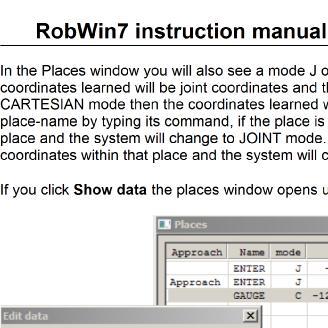
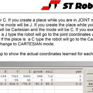
5 Cartesian absolute move sends the robot to the absolute Cartesian position that you specify. This can be more convenient than the MOVETO commands in RoboForth because you can set up the hand and wrist (and yaw) parameters at the same time whereas in RoboForth you must use TOOL to set them up before you use MOVETO. Once the robot is in the right workspace you can then use MOVETO commands or TOOL This will move the robot to zero on the X axis, 300mm from center on the Y axis and zero on the Z axis (which for R12/R17 means level with the shoulder pivot). Wrist rotates to 90 degrees i.e. points downwards. Cartesian relative move same as above but moves the robot by the amount specified. Start, Calibrate, Home sends the commands START CALIBRATE HOME Teach same as TEACH but sets the teach speed with a dialog box. Jog same as JOG but sets the jog increment with a dialog box. Grip toggle same as the grip icon in the tool bar. Joint mode sends JOINT and sets joint mode in the controller. Cartesian mode sends CARTESIAN and sets Cartesian mode in the controller. Segmented sends SEGMENTED which cancels CONTINUOUS path mode. Continuous sends CONTINUOUS which sets CONTINUOUS path mode. Project New start a new project. This creates 3 new windows: Routes lists and controls all the routes you create (see RoboForth manual). Places lists and controls all the places you create (see RoboForth manual). ED2 window this is where you write your RoboForth program that determines what the robot does and when, utilizing the data (routes and places) that you have created. When the project is saves it creates 3 new files: name.run this is a binary image of the routes and places you created (in the upper bank of memory) name.ed1 this is a list of the names of the routes and places that are compiled into the dictionary. name.ed2 this is the text you create in the ED2 window. Open open an existing project Close, Save, Save-as usual Windows conventions. To start a new project click project, new and choose a name for your project for example myprog. When the project is open you will see three more windows: routes, places and a window labeled myprog.ed2 We advise (from experience) to move the communications window to the bottom and to re-arrange the other three so all are visible. The system sends commands ROBOFORTH and STARTOVER to the controller which you can see in the communications window. This clears out the controller ready for the new session. 5

6 Macro The macro bar is a line of 10 buttons that you can program yourself. You give a button your own name and also specify the text that is sent to the controller when the button is pressed. 1. click macro 2. open an existing file or create a new one 3. click macro again 4. click edit 5. you can see a list of existing buttons if any. 6. click new to add a new button 7. enter the name of the button that will appear on the actual button 8. in the lower box enter the text that will be sent to the controller. This can be more than one word. If so you can put the words on one line, separated by spaces or on new lines type control-enter for a new line as in the example below. 9. click ok 10.For another button repeat from to edit an existing button highlight the existing button name and click edit 12.to use a button simply click it and the associated text is sent to the controller. 6

7
8


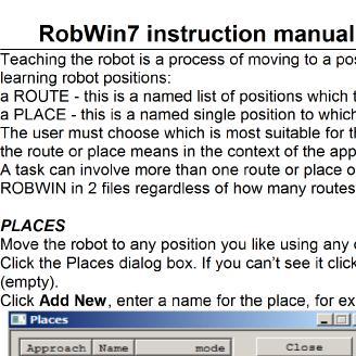
9 ROUTES Find the routes window or click Project Routes. Click the New button SEQUENTIAL ROUTE IN JOINT MODE Enter a name, for example I66 You must then reserve some space for the route. The default is 20 but you can reserve hundreds if you think you ll need them. Click OK and this creates a window for the new route:


10
.")
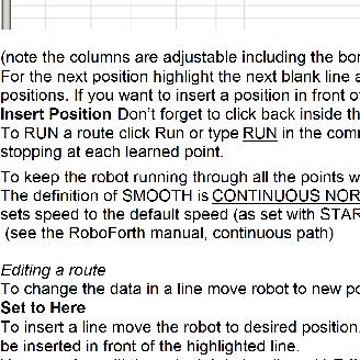
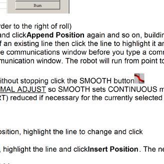
11 Using the teach pad to learn a route Click on button to activate the teach pad, as described above. Do not type TEACH it is not the same. For Cartesian mode click the J button and jog the robot to the desired position. When satisfied with the position press the red key (or green on Android pad). This learns the position into the currently selected route. The red X deletes the last line learned. Creating a task with both routes and places Click on the ED2 window. You can now enter definitions in this window, for example : TASK JIG I66 RUN ; To download this file to the controller click on the To test this function simply type TASK A variation might be: : TASK SPEED! JIG SPEED! I66 CONTINUOUS ADJUST RUN SPEED! ; button. This also automatically saves the file to disk. Each time you click the download button the new text is automatically saved in the.ed2 file however you need to click project, save to save the data on disk (saves to the.ed1 and.run files). SEQUENTIAL ROUTE IN CARTESIAN MODE In the routes window click New. In the route box enter the name of the route then click the Cartesian radar button and enter the number of lines to be reserved. 11

 Click Interpolate To change an end point (line 1 or 10) move")
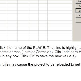
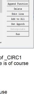
12 Reference routes in Cartesian mode Row A Row is a list of positions that would not be RUN but are just used as references, for example positions in a rack of test tubes. In the routes window click New, enter the name of the route then click the Cartesian and Row radar buttons and enter the number of lines to reserve and the number of positions in the route. Naturally the number of lines reserved should be more than the number of positions or columns in the row. Allow at least one more line for an approach position. Click OK.. Move the robot to the first position and highlight line 1 Then move to the last position and highlight the last line (10 in this case) Click Interpolate To change an end point (line 1 or 10) move the robot there and click Set to Here. Then click Interpolate again 12

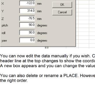
13 You can also edit a line manually with Edit Line This brings up a dialog box called Edit data which asks for the amounts to move in each axis. You can shift all the coordinates of all the lines in any direction with Add to All. The same Edit data box appears and values entered there are added to each line in the route. Similar to the approach position of a PLACE name you can also have an approach position for a ROW. It is simply an extra line (11 in this case) with relative coordinates in it. These coordinate values are added to any of the lines by the controller to give an approach position for all the lines. To create the line go to any position (usually the last line because that is the last one you have learned) and do a relative move, for example MOVE to move up 50mm in Z. Or use the teach pad in Jog mode. Then click Set Approach. The relative move will appear as the extra line with an R by it. This means the data in this line is relative. Whenever you GoTo this line the robot will simply move by the relative amounts (50mm in Z in this example). Highlight any line and click Go near and the robot will go to the approach position for that line which is the sum of that line and the R line. In RoboForth the commands are n NEAR and n INTO. 13
 With a grid you need to learn")

14 Grid To create a matrix choose new route. In the dialog box enter the name of the route, click grid the number of rows and collums. Make sure you reserve enough space for the number of lines plus an extra one or two for approach position(s) With a grid you need to learn 3 corners of the matrix. These are indicated by an asterisk by the relevant lines. Once you have learned each of the 3 lines click interpolate. Next you can learn an approach position in the same way as for a row. See example below with 10 columns by 5 rows plus one approach position. 14
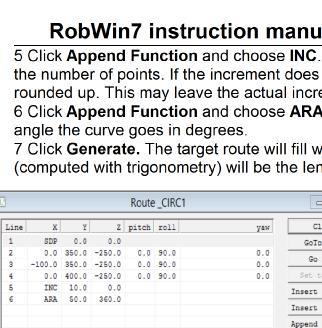
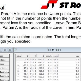
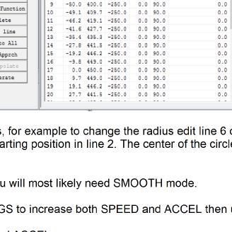
15 Curve Generator The curve generator allows you to construct a path mathematically that comprises straight lines and curves by specifying the length and direction of lines, radius, angle and orientation of curves. To do this you start with a reference route that lists the specifications of the curve. You then click the generate button and an associated route is filled with the calculated coordinates the robot is to follow. Don't forget that when you run this route you will most likely need SMOOTH mode i.e. SMOOTH RUN If this results in too low speed use SETTINGS to increase both SPEED and ACCEL then use SMOOTH again. Click New generator and provide a name. This will create two routes, the target route using your provided name and the generator route with the same name preceded by underscore, e.g. R1 and _R1. It is the target route R1 that you will eventually RUN. It s useful to open this route so you can see the calculated coordinates appear. Reserve enough lines for each. The default is 20 lines for the generator and 200 for the ultimate coordinates however you typically need more than 20 for complex shapes. Change to 100. Next click Append Function. Choose SDP (Start,Direction,Point). Leave Param A and B at zero. Once you have done this you need to enter 3 lines of coordinates: The first line following is the start point. Its hand angle values are also copied to all lines in the generated route. The second line is any point on the line of the starting direction. Its angle values are ignored. The actual coordinates are not important, it just tells the system what direction we are going in. The third line is any point on the plane we wish to define to the left of the starting direction. Its angle values are also ignored. Being to the left defines which side of the plane we are considering as upwards and how we measure angles as positive anticlockwise. Sometimes it is easier just to click Append position 3 times and then edit them. Make a straight line 1 Click Append Function and choose SDP - leave both params zero. 2 Then enter the 3 coordinates: first line is the starting position of the line. You would typically use the current position of the robot so just click Append position. You can edit this later. 3 Pick some position on your line. This is simply the direction the line is heading. It can have X Y and Z values for a line at an angle in space. Probably the easiest is to move the robot to a position on your propose line and click Append position. 4 Click Append position again. The data in this third line is not used. Any values are ok and ignored. 5 Click Append Function and choose INC. Param A is the distance between points. This determines the number of points. If the increment does not fit in the number of points then the number of points is rounded up. This may leave the actual increment less than you specified. 6 Click Append Function and choose LIN. Param A is the length of the line in mm. Leave Param B zero. 7 Click Generate. The target route will fill with the calculated coordinates. The total length of the line will be the length you specified. A line length of 100mm and an increment of 10mm will produce 11 lines. 15
16 Make a curve 1 Click Append Function and choose SDP - leave both params zero. 2 Then enter the 3 coordinates: first line is the starting position of the curve. You would typically use the current position of the robot so just click Append position. You can edit this later. 3 Pick some position on a line in the direction that the robot would follow if it were a straight line. This line is a tangent to the curve being generated. Probably the easiest is to move the robot to a position on this hypothetical line and click Append position. 4 Click Append position again. This needs to be any point to the left of the curve, i.e. somewhere inside the curve. This tells the system the plane of the curve. A good place to choose would be the center of the curve but that is not critical anywhere on the plane will do. If the X value of this point is positive of the starting point then the curve will arc towards the positive X value. If the X value is negative then the curve will arc to negative X. A similar rule for the other axes. An easy way of doing the above 3 lines (steps 2,3,4) is to get the robot to the starting position using the Jog function. Press the tick key. Move sideways one increment only and press tick for the second line, then move at right angles to this (in the direction of the curve) one increment and press tick a third time. Then escape. 5 Click Append Function and choose INC. Param A is the distance between points. This determines the number of points. If the increment does not fit in the number of points then the number of points is rounded up. This may leave the actual increment less than you specified. Leave Param B at 0. 6 Click Append Function and choose ARA. Param A is the radius of the curve in mm. Param B is the angle the curve goes in degrees. 7 Click Generate. The target route will fill with the calculated coordinates. The total length of the line (computed with trigonometry) will be the length you specified. Add a curve to a straight line 1 Having created the line as in make a straight line above, go back and edit line 4 so that coordinate lies on the plane on which the curve will be made. 2 Click Append Function and choose ARA. Param A is the radius of the curve in mm. Param B is the angle the curve goes in degrees. 3 Click Generate. The target route will fill with the calculated coordinates. The total length of the line (computed with trigonometry) will be the length you specified. When you have a shape made from more than one segment (e.g. straight line plus a curve or two curves) you will see in the target route pairs of lines with the same coordinates. You need to delete one of them. Such a route may be run in continuous mode CONTINUOUS RUN. If you have two lines the same you will get the too tight error message. If you do not have 2 lines the same but get this message then you need to reduce SPEED or increase ACCEL. A word ADJUST reduces speed to a valid value. The second and more logical mode is CONTINUOUS TIMED. Set a value for SEGTIME using (val) SEGTIME! Or using SETTINGS. Now when you RUN the route the time for each segment will be the same. Since you made all the segments the same length with INC the result is more or less constant speed. If you get too tight error it's because the SEGTIME is too short for one of the segments. One thing you can do is add a very short segment to the beginning (with insert) and to the end (with append) which allows an acceleration and deceleration space. Then you can reduce the value of SEGTIME and increase the real speed. 16

17 Example and explanation. In _R1 Line 1 the starting command SDP Line 2 the starting coordinates of the line, also specifying the hand pitch and roll. Line 3 the heading of the line i.e. heading off in the Y direction in this case. Line 4 a point on the plane of the curve and inside it. So this curve will arc round in the X direction. Line 5 set increment to 20mm Line 6 make a line 100mm long. Line 7 for the curve, change the increment to 31.4mm Line 8 specify the curve as having a radius of 100mm and an arc of 90 degrees. Then click generate. In R1 you can see the straight line from line 1 to line 6, 100mm long comprising 6 lines and 5 segments. Then the curve starts. At a radius of 100mm and an increment of 31.4 this works out to 5 segments, i.e. from lines 6 to 12. It finishes up at X=100 and Y=300 and heading in the X direction. 17
18 Make a circle A circle is just a curve 360 degrees. Drive the robot to the nearest point on the circle to the robot. If you want the hand to be horizontal you will need to enter the length of the hand. When you send the robot to a particular Cartesian position it is the center of the wrist that occupies that position, the intersection of pitch and roll axes. You will want the center of the object to be there so you need to measure that distance. Enter TOOL WRIST PITCH 0.0 WRIST ROLL 90.0 or 0.0 as appropriate TOOL LENGTH (or whatever distance it is) ALIGN N EXECUTE? Y OK In the routes window click new generator and give it a name. Let's choose CIRC for the name. You will get 2 new routes, _CIRC and CIRC 1 Click Append Function and choose SDP - leave both params zero. 2 Then enter the 3 coordinates: first line is the starting position of the curve. You would typically use the current position of the robot so just click Append position. You can edit this later. 3 Pick some position on a line in the direction that the robot would follow if it were a straight line. This line is a tangent to the curve being generated. Probably the easiest is to move the robot to a position on this hypothetical line and click Append position. 4 Click Append position again. This needs to be any point to the left of the curve, i.e. somewhere inside the curve. This tells the system the plane of the curve. A good place to choose would be the center of the curve but that is not critical anywhere on the plane will do. If the X value of this point is positive of the starting point then the curve will arc towards the positive X value. If the X value is negative then the curve will arc to negative X. A similar rule for the other axes. An easy way of doing the above 3 lines (steps 2,3,4) is to get the robot to the starting position using the Jog function. Press the tick key. Move sideways one increment only and press tick for the second line, then move at right angles to this (in the direction of the curve) one increment and press tick a third time. Then press esc to get back to RobWin. For the Nexus press esc then its stop button. 18
19
20 IMPORTANT STEP WHEN CREATING A ROUTE WITH MORE THAN ONE SECTION If you add a section with the same starting coordinates as the last line of the previous section you will see 2 consecutive lines with the same coordinates. These will not run in SMOOTH mode and in TIMED mode the robot will stop and pause on that coordinate for SEGTIME. Therefore at the end of each section make a note of the last line. When the target route is complete go back to those lines and delete the duplicates. If you click the generate button you will have to delete those lines again. Using RobWin with Bluetooth. When you switch on the controller the red LED on the adapter will come on and the blue LED will start flashing. On your PC go to bluetooth and search for devices. You will see serial adapter. Pair with that using the PIN Next go to control panel, device manager and expand COM ports. You will see 2 new COM ports. Note the lower number. Go to comms, configure and choose the number from above. RobWin does not accept COM numbers greater than 9. There may be a few seconds delay then you will see a message. Ignore any error message, press enter and you should see OK. Using RobWin to communicate with a remote robot over the Internet. You will need to install Virtual Serial Port from the folder Ethernet > HW VSP3s. Run HW VSP3s.exe Check Standalone Application click next, next, install Confirm firewall exceptions, answer yes, finish. Virtual Serial Port is now installed. On desktop double-click the icon HW Virtual Serial Port Click the virtual serial port tab. Select a com, e.g. com3 Click create COM As soon as the red cross Delete COM appears communication is ready Run RobWin7 If you are not already in communication click Comm, configure. choose COM3 (or whatever port you created with the VSP). Note: communication over the Internet is very slow. Validate It is a bad idea to define words that are already defined in RoboForth. For example TELL WAIST 1000 MOVE works as you expect. But if you define USER MOVE now MOVE no longer has its original meaning. TELL. MOVE will never work again. Click Project Validate and this will list all words you have created (including Places and Routes) that were already in the RoboForth dictionary. RobWin7 manual Sands Technology International. Revision
Using the Android teach-pad
 with ROBWIN 7 and ROBOFORTH II v15/16 Components The components of the system are: 7 inch hand-held tablet Android software (apk or app ) already loaded. Bluetooth adaptor Serial port on rear of controller
RoboForth Tutorial page 1
 RoboForth Tutorial page 1 Introduction ROBOTICS SELF-LEARN TUTORIAL 5-AXIS ROBOTS R12,R17 Aim of the tutorial is to provide a comprehensive introduction to the programming and use of ST robot arms using
RoboForth Tutorial page 1
 RoboForth Tutorial page 1 Introduction ROBOTICS SELF-LEARN TUTORIAL 6-AXIS ROBOTS R12,R17 Aim of the tutorial is to provide a comprehensive introduction to the programming and use of ST robot arms using
Software Manual. Version: H BENCHTOP ROBOT SOFTWARE USER GUIDE Version H
 Software Manual Version: H6.1.1.292 BENCHTOP ROBOT SOFTWARE USER GUIDE Version H6.1.1.293 Software Manual Table of Contents SECTION 1: INTRODUCTION... 5 1.1 Introduction...6 1.2 Safety...6 1.3 New Features...6
SCORBASE. User Manual. Version 5.3 and higher. for SCORBOT ER-4u SCORBOT ER-2u ER-400 AGV Mobile Robot. Catalog #100342, Rev. G
 SCORBASE Version 5.3 and higher for SCORBOT ER-4u SCORBOT ER-2u ER-400 AGV Mobile Robot User Manual Catalog #100342, Rev. G February 2006 Copyright 2006 Intelitek Inc. SCORBASE USER MANUAL Catalog #100342,
This overview summarizes topics described in detail later in this chapter.
 20 Application Environment: Robot Space and Motion Overview This overview summarizes topics described in detail later in this chapter. Describing Space A coordinate system is a way to describe the space
QuickTutor. An Introductory SilverScreen Modeling Tutorial. Solid Modeler
 QuickTutor An Introductory SilverScreen Modeling Tutorial Solid Modeler TM Copyright Copyright 2005 by Schroff Development Corporation, Shawnee-Mission, Kansas, United States of America. All rights reserved.
TABLE OF CONTENTS. Page 2 35
 TABLE OF CONTENTS INTRODUCTION... 3 WARNING SIGNS AND THEIR MEANINGS... 3 1. ABOUT THE PULSE ROBOT... 4 1.1. The hardware and software... 4 1.2. The operating states of the PULSE robot... 5 1.3. Safe operation
Tangents. In this tutorial we are going to take a look at how tangents can affect an animation.
 Tangents In this tutorial we are going to take a look at how tangents can affect an animation. One of the 12 Principles of Animation is called Slow In and Slow Out. This refers to the spacing of the in
Exercise 3. Task Programs EXERCISE OBJECTIVE
 Exercise 3 Task Programs EXERCISE OBJECTIVE In this exercise, you will be introduced to task programs and task commands available in Robotics. You will also be introduced to the Task Editor window in Robotics.
Lesson 14 Blends. For Resources go to > click on the Creo Parametric Book cover
 Lesson 14 Blends Figure 14.1 Cap OBJECTIVES Create a Parallel Blend feature Use the Shell Tool Create a Swept Blend REFERENCES AND RESOURCES For Resources go to www.cad-resources.com > click on the Creo
Function. Description
 Function Check In Get / Checkout Description Checking in a file uploads the file from the user s hard drive into the vault and creates a new file version with any changes to the file that have been saved.
Working with the Dope Sheet Editor to speed up animation and reverse time.
 Bouncing a Ball Page 1 of 2 Tutorial Bouncing a Ball A bouncing ball is a common first project for new animators. This classic example is an excellent tool for explaining basic animation processes in 3ds
1 Overview Sequencer PS2 Control...26 C O N T E N T S INTRODUCTION...5 USER INTERFACE...6 CONNECTING...7 SIMULATOR...
 AL5 ARM GUIDE C O N T E N T S CHAPTER 1 1 Overview...4 INTRODUCTION...5 USER INTERFACE...6 CONNECTING...7 CONNECTING VIA USB (FOR SSC-32U, RB-LYN-850)...7 CONNECTING VIA SERIAL CABLE (FOR DISCONTINUED
2 SELECTING AND ALIGNING
 2 SELECTING AND ALIGNING Lesson overview In this lesson, you ll learn how to do the following: Differentiate between the various selection tools and employ different selection techniques. Recognize Smart
Lesson 12: Preparing for Post Processing
 12 Lesson 12: Preparing for Post Processing Learning Objectives In this lesson you will: Rename reference designators on the board design Backannotate changes made in the OrCAD and Allegro PCB Editor to
Autodesk Fusion 360 Training: The Future of Making Things Attendee Guide
 Autodesk Fusion 360 Training: The Future of Making Things Attendee Guide Abstract After completing this workshop, you will have a basic understanding of editing 3D models using Autodesk Fusion 360 TM to
Appendix B: Creating and Analyzing a Simple Model in Abaqus/CAE
 Getting Started with Abaqus: Interactive Edition Appendix B: Creating and Analyzing a Simple Model in Abaqus/CAE The following section is a basic tutorial for the experienced Abaqus user. It leads you
TPC Desktop Series. Alignments Learning Guide 1/18
 TPC Desktop Series Alignments Learning Guide 1/18 NOTICE The information in this document is subject to change without notice. TRAVERSE PC. Inc. assumes no responsibility for any errors that may appear
The Department of Construction Management and Civil Engineering Technology CMCE-1110 Construction Drawings 1 Lecture Introduction to AutoCAD What is
 The Department of Construction Management and Civil Engineering Technology CMCE-1110 Construction Drawings 1 Lecture Introduction to AutoCAD What is AutoCAD? The term CAD (Computer Aided Design /Drafting)
Welcome to MicroStation
 Welcome to MicroStation Module Overview This module will help a new user become familiar with the tools and features found in the MicroStation design environment. Module Prerequisites Fundamental knowledge
Making Windows XP work for you
 Making Windows XP work for you With each version of Windows that has been released over the past several years, Microsoft and other developers have been made aware of the issues surrounding accessibility
SolidWorks Intro Part 1b
 SolidWorks Intro Part 1b Dave Touretzky and Susan Finger 1. Create a new part We ll create a CAD model of the 2 ½ D key fob below to make on the laser cutter. Select File New Templates IPSpart If the SolidWorks
Learning Worksheet Fundamentals
 1.1 LESSON 1 Learning Worksheet Fundamentals After completing this lesson, you will be able to: Create a workbook. Create a workbook from a template. Understand Microsoft Excel window elements. Select
PART 7. Getting Started with Excel
 PART 7 Getting ed with Excel When you start the application, Excel displays a blank workbook. A workbook is a file in which you store your data, similar to a three-ring binder. Within a workbook are worksheets,
SolidWorks 2½D Parts
 SolidWorks 2½D Parts IDeATe Laser Micro Part 1b Dave Touretzky and Susan Finger 1. Create a new part In this lab, you ll create a CAD model of the 2 ½ D key fob below to make on the laser cutter. Select
Working with Charts Stratum.Viewer 6
 Working with Charts Stratum.Viewer 6 Getting Started Tasks Additional Information Access to Charts Introduction to Charts Overview of Chart Types Quick Start - Adding a Chart to a View Create a Chart with
Lesson 1 Parametric Modeling Fundamentals
 1-1 Lesson 1 Parametric Modeling Fundamentals Create Simple Parametric Models. Understand the Basic Parametric Modeling Process. Create and Profile Rough Sketches. Understand the "Shape before size" approach.
To familiarize of 3ds Max user interface and adapt a workflow based on preferences of navigating Autodesk 3D Max.
 Job No: 01 Duration: 8H Job Title: User interface overview Objective: To familiarize of 3ds Max user interface and adapt a workflow based on preferences of navigating Autodesk 3D Max. Students should be
LinkMotion and CorelDraw 9, 10, 11, 12, X3, X4, X5, X6, X7 and X8:
 LinkMotion and CorelDraw 9, 10, 11, 12, X3, X4, X5, X6, X7 and X8: After you install LinkMotion software and set up all settings launch CorelDraw software. Important notes: Solustan s LinkMotion driver
3 AXIS STANDARD CAD. BobCAD-CAM Version 28 Training Workbook 3 Axis Standard CAD
 3 AXIS STANDARD CAD This tutorial explains how to create the CAD model for the Mill 3 Axis Standard demonstration file. The design process includes using the Shape Library and other wireframe functions
Opening a Data File in SPSS. Defining Variables in SPSS
 Opening a Data File in SPSS To open an existing SPSS file: 1. Click File Open Data. Go to the appropriate directory and find the name of the appropriate file. SPSS defaults to opening SPSS data files with
3D Body. Summary. Modified by Admin on Sep 13, Parent page: Objects
 3D Body Old Content - visit altium.com/documentation Modified by Admin on Sep 13, 2017 Parent page: Objects A sphere, a cylinder and 4 extruded rectangles have been used to create the 3D body for an LED.
Tips & Tricks for Microsoft Word
 T 330 / 1 Discover Useful Hidden Features to Speed-up Your Work in Word For what should be a straightforward wordprocessing program, Microsoft Word has a staggering number of features. Many of these you
Autodesk Inventor Design Exercise 2: F1 Team Challenge Car Developed by Tim Varner Synergis Technologies
 Autodesk Inventor Design Exercise 2: F1 Team Challenge Car Developed by Tim Varner Synergis Technologies Tim Varner - 2004 The Inventor User Interface Command Panel Lists the commands that are currently
Producing Project Deliverables: Creating a Plan Set
 Practice Workbook This workbook is designed for use in Live instructor-led training and for OnDemand selfstudy. The explanations and demonstrations are provided by the instructor in the classroom, or in
Introduction to Minitab 1
 Introduction to Minitab 1 We begin by first starting Minitab. You may choose to either 1. click on the Minitab icon in the corner of your screen 2. go to the lower left and hit Start, then from All Programs,
Tutorial 3: Constructive Editing (2D-CAD)
") (2D-CAD) The editing done up to now is not much different from the normal drawing board techniques. This section deals with commands to copy items we have already drawn, to move them and to make multiple
(2D-CAD) The editing done up to now is not much different from the normal drawing board techniques. This section deals with commands to copy items we have already drawn, to move them and to make multiple
Chapter-2 Digital Data Analysis
 Chapter-2 Digital Data Analysis 1. Securing Spreadsheets How to Password Protect Excel Files Encrypting and password protecting Microsoft Word and Excel files is a simple matter. There are a couple of
Codesoft 6 Premier Overview Manual. Thermocode Series 2 (all Printers)
") Thermocode Series 2 Codesoft Overview Manual. (Issue 4.1) 28 July 2003 Page No. - 1 - Open Date Equipment Ltd. Unit s 8 & 9 Puma Trade Park, 145 Morden Road, Mitcham, Surrey. CR4 4DG United Kingdom. Tel:-
Thermocode Series 2 Codesoft Overview Manual. (Issue 4.1) 28 July 2003 Page No. - 1 - Open Date Equipment Ltd. Unit s 8 & 9 Puma Trade Park, 145 Morden Road, Mitcham, Surrey. CR4 4DG United Kingdom. Tel:-
SOFTWARE KR C... User Programming. KUKA System Software (KSS) Release 4.1. Issued: 14 Jul 2003 Version: 03. ProgAnwenderR en.
 Release 4.1. Issued: 14 Jul 2003 Version: 03. ProgAnwenderR en.") SOFTWARE KR C... User Programming KUKA System Software (KSS) Release 4.1 Issued: 14 Jul 2003 Version: 03 1of 60 e Copyright KUKA Roboter GmbH This documentation or excerpts therefrom may not be reproduced
SOFTWARE KR C... User Programming KUKA System Software (KSS) Release 4.1 Issued: 14 Jul 2003 Version: 03 1of 60 e Copyright KUKA Roboter GmbH This documentation or excerpts therefrom may not be reproduced
solidthinking Inspired Tutorials 2009 solidthinking, Inc. for Mac
 solidthinking Inspired Tutorials 2009 solidthinking, Inc. for Mac Table of Contents Quick Start Tutorials 3 Tutorial 11: Simple... Bridge 4 Tutorial 22: Desk... 12 Tutorial 33: Bookcase... 35 2 1 Quick
SCENE FILE MANIPULATION SCENE FILE MANIPULATION GETTING STARTED MODELING ANIMATION MATERIALS + MAPPING RENDERING. Saving Files. Save.
 SCENE FILE MANIPULATION SCENE FILE MANIPULATION There are several things you can do with a scene file in 3ds Max. You can save a file, save a file temporarily and retrieve it, and combine scene files.
ASIC-200 Version 5.0. integrated industrial control software. HMI Guide
 ASIC-200 Version 5.0 integrated industrial control software HMI Guide Revision Description Date C Name change, correct where applicable with document 4/07 HMI Guide: 139168(C) Published by: Pro-face 750
4 TRANSFORMING OBJECTS
 4 TRANSFORMING OBJECTS Lesson overview In this lesson, you ll learn how to do the following: Add, edit, rename, and reorder artboards in an existing document. Navigate artboards. Select individual objects,
Complete Tutorial (Includes Schematic & Layout)
") Complete Tutorial (Includes Schematic & Layout) Download 1. Go to the "Download Free PCB123 Software" button or click here. 2. Enter your e-mail address and for your primary interest in the product. (Your
Complete Tutorial (Includes Schematic & Layout) Download 1. Go to the "Download Free PCB123 Software" button or click here. 2. Enter your e-mail address and for your primary interest in the product. (Your
Navigator Software User s Manual. User Manual. Navigator Software. Monarch Instrument Rev 0.98 May Page 1 of 17
 User Manual Navigator Software Monarch Instrument Rev 0.98 May 2006 Page 1 of 17 Contents 1. NAVIGATOR SOFTWARE 2. INSTALLATION 3. USING NAVIGATOR SOFTWARE 3.1 STARTING THE PROGRAM 3.2 SYSTEM SET UP 3.3
BoA Tools Page 1 / 31
 BoA Tools Page 1 / 31 Standard tools Overview 2 Work pane 3 3D-2D file Main palette 6 Layout Main Palette 9 Navigation tools 11 Workplane Palette 14 Cursor Palette 21 Numeric control 24 Selection by Criteria
4. If you are prompted to enable hardware acceleration to improve performance, click
 Exercise 1a: Creating new points ArcGIS 10 Complexity: Beginner Data Requirement: ArcGIS Tutorial Data Setup About creating new points In this exercise, you will use an aerial photograph to create a new
MET 107 Drawing Tool (Shapes) Notes Day 3
 Notes Day 3") MET 107 Drawing Tool (Shapes) Notes Day 3 Shapes: (Insert Tab Shapes) Example: Select on the rounded rectangle Then use the mouse to position the upper left corner and produce the size by dragging out
MET 107 Drawing Tool (Shapes) Notes Day 3 Shapes: (Insert Tab Shapes) Example: Select on the rounded rectangle Then use the mouse to position the upper left corner and produce the size by dragging out
R12 Robot Manual page
 R2 Robot Manual page 205-04-09 Welcome! to the R2-500 Firefly robot arm User Manual We hope you enjoy your experience. Any problems at all just contact us. support@strobotics.com + 609 584 7522 +44 223
Quick Start Guide. ARIS Architect. Version 9.8 Service Release 2
 ARIS Architect Version 9.8 Service Release 2 October 2015 This document applies to ARIS Version 9.8 and to all subsequent releases. Specifications contained herein are subject to change and these changes
Get comfortable using computers
 Mouse A computer mouse lets us click buttons, pick options, highlight sections, access files and folders, move around your computer, and more. Think of it as your digital hand for operating a computer.
Revit Architecture 2015 Basics
 Revit Architecture 2015 Basics From the Ground Up Elise Moss Authorized Author SDC P U B L I C AT I O N S Better Textbooks. Lower Prices. www.sdcpublications.com Powered by TCPDF (www.tcpdf.org) Visit
Arduino IDE Friday, 26 October 2018
 Arduino IDE Friday, 26 October 2018 12:38 PM Looking Under The Hood Of The Arduino IDE FIND THE ARDUINO IDE DOWNLOAD First, jump on the internet with your favorite browser, and navigate to www.arduino.cc.
2 Getting Started. Getting Started (v1.8.6) 3/5/2007
 3/5/2007") 2 Getting Started Java will be used in the examples in this section; however, the information applies to all supported languages for which you have installed a compiler (e.g., Ada, C, C++, Java) unless
2 Getting Started Java will be used in the examples in this section; however, the information applies to all supported languages for which you have installed a compiler (e.g., Ada, C, C++, Java) unless
Pharos Designer 2. Copyright Pharos Architectural Controls (15/1/2015)
") Pharos Designer 2 Welcome Welcome to Pharos Designer 2. We are delighted to introduce you to an entirely new version of the Pharos Designer software that picks up where the venerable and much- loved version
Pharos Designer 2 Welcome Welcome to Pharos Designer 2. We are delighted to introduce you to an entirely new version of the Pharos Designer software that picks up where the venerable and much- loved version
Forms for Android Version Manual. Revision Date 12/7/2013. HanDBase is a Registered Trademark of DDH Software, Inc.
 Forms for Android Version 4.6.300 Manual Revision Date 12/7/2013 HanDBase is a Registered Trademark of DDH Software, Inc. All information contained in this manual and all software applications mentioned
CROMWELLSTUDIOS. Content Management System Instruction Manual V1. Content Management System. V1
 Content Management System Instruction Manual V1 www.cromwellstudios.co.uk Cromwell Studios Web Services Content Management System Manual Part 1 Content Management is the system by which you can change
Let s Make a Front Panel using FrontCAD
 Let s Make a Front Panel using FrontCAD By Jim Patchell FrontCad is meant to be a simple, easy to use CAD program for creating front panel designs and artwork. It is a free, open source program, with the
EDGE, MICROSOFT S BROWSER
 EDGE, MICROSOFT S BROWSER To launch Microsoft Edge, click the Microsoft Edge button (it s the solid blue E) on the Windows Taskbar. Edge Replaces Internet Explorer Internet Explorer is no longer the default
Trio Motion Technology 4-2. Motion Perfect v3
 MOTION PERFECT V3 4 Trio Motion Technology 4-2 Software Reference Manual Introduction to Motion Perfect 3 Motion Perfect 3 is an Microsoft Windows based application for the PC, designed to be used in conjunction
Chapter 9 Slide Shows
 Impress Guide Chapter 9 Slide Shows Transitions, animations, and more Copyright This document is Copyright 2007 2011 by its contributors as listed below. You may distribute it and/or modify it under the
StickFont v2.12 User Manual. Copyright 2012 NCPlot Software LLC
 StickFont v2.12 User Manual Copyright 2012 NCPlot Software LLC StickFont Manual Table of Contents Welcome... 1 Registering StickFont... 3 Getting Started... 5 Getting Started... 5 Adding text to your
Using Coordinate Systems
 Using Coordinate Systems In This Chapter 5 As you draw you use the coordinate system to specify points in the drawing. You can locate and use your own movable user coordinate system (UCS) for working on
Part II: Creating Visio Drawings
 128 Part II: Creating Visio Drawings Figure 5-3: Use any of five alignment styles where appropriate. Figure 5-4: Vertical alignment places your text at the top, bottom, or middle of a text block. You could
All textures produced with Texture Maker. Not Applicable. Beginner.
 Tutorial for Texture Maker 2.8 or above. Note:- Texture Maker is a texture creation tool by Tobias Reichert. For further product information please visit the official site at http://www.texturemaker.com
Getting Started (1.8.7) 9/2/2009
 9/2/2009") 2 Getting Started For the examples in this section, Microsoft Windows and Java will be used. However, much of the information applies to other operating systems and supported languages for which you have
2 Getting Started For the examples in this section, Microsoft Windows and Java will be used. However, much of the information applies to other operating systems and supported languages for which you have
ezimagex2 User s Guide Version 1.0
 ezimagex2 User s Guide Version 1.0 Copyright and Trademark Information The products described in this document are copyrighted works of AVEN, Inc. 2015 AVEN, Inc. 4595 Platt Rd Ann Arbor, MI 48108 All
Skills Exam Objective Objective Number
 Overview 1 LESSON SKILL MATRIX Skills Exam Objective Objective Number Starting Excel Create a workbook. 1.1.1 Working in the Excel Window Customize the Quick Access Toolbar. 1.4.3 Changing Workbook and
v Overview SMS Tutorials Prerequisites Requirements Time Objectives
 v. 12.2 SMS 12.2 Tutorial Overview Objectives This tutorial describes the major components of the SMS interface and gives a brief introduction to the different SMS modules. Ideally, this tutorial should
HOUR 12. Adding a Chart
 HOUR 12 Adding a Chart The highlights of this hour are as follows: Reasons for using a chart The chart elements The chart types How to create charts with the Chart Wizard How to work with charts How to
FREDOSCALE - Plugin for Sketchup
 FREDOSCALE - Plugin for Sketchup Free Scaling and Other Transformations VERSION 2.5 01 SEP 13 1. Overview FredoScale applies geometric transformations to a selection. - For many of them, the selection
1 Interface Fundamentals
 1 Interface Fundamentals Windows The Media Composer interface is focused on three primary windows: the Composer, the Timeline and the Project. The Composer window contains the source and record monitors
NURBS modeling for Windows. Training Manual Level 1
 NURBS modeling for Windows Training Manual Level 1 Rhino Level 1 Training 2nd Ed.doc Robert McNeel & Associates 1997-2000 All Rights Reserved. Printed in U.S.A. Copyright by Robert McNeel & Associates.
Exercise Guide. Published: August MecSoft Corpotation
 VisualCAD Exercise Guide Published: August 2018 MecSoft Corpotation Copyright 1998-2018 VisualCAD 2018 Exercise Guide by Mecsoft Corporation User Notes: Contents 2 Table of Contents About this Guide 4
Creating and Analyzing a Simple Model in Abaqus/CAE
 Appendix B: Creating and Analyzing a Simple Model in Abaqus/CAE The following section is a basic tutorial for the experienced Abaqus user. It leads you through the Abaqus/CAE modeling process by visiting
GstarCAD Complete Features Guide
 GstarCAD 2017 Complete Features Guide Table of Contents Core Performance Improvement... 3 Block Data Sharing Process... 3 Hatch Boundary Search Improvement... 4 New and Enhanced Functionalities... 5 Table...
Rhinoceros NURBS modeling for Windows. Version 1.0 Training Manual Level 1
 Rhinoceros NURBS modeling for Windows Version 1.0 Training Manual Level 1 rhinolevel 1.doc Robert McNeel & Associates 1997. All Rights Reserved. Printed in U.S.A. Copyright by Robert McNeel & Associates.
Using Flash Animation Basics
 Using Flash Contents Using Flash... 1 Animation Basics... 1 Exercise 1. Creating a Symbol... 2 Exercise 2. Working with Layers... 4 Exercise 3. Using the Timeline... 6 Exercise 4. Previewing an animation...
Modeling a Gear Standard Tools, Surface Tools Solid Tool View, Trackball, Show-Hide Snaps Window 1-1
 Modeling a Gear This tutorial describes how to create a toothed gear. It combines using wireframe, solid, and surface modeling together to create a part. The model was created in standard units. To begin,
Lesson 14 Blends. For Resources go to > click on the Creo Parametric 2.0 Book cover
 Lesson 14 Blends Figure 14.1 Cap OBJECTIVES Create a Parallel Blend feature Use the Shell Tool Create a Hole Pattern REFERENCES AND RESOURCES For Resources go to www.cad-resources.com > click on the Creo
Randy H. Shih. Jack Zecher PUBLICATIONS
 Randy H. Shih Jack Zecher PUBLICATIONS WWW.SDCACAD.COM AutoCAD LT 2000 MultiMedia Tutorial 1-1 Lesson 1 Geometric Construction Basics! " # 1-2 AutoCAD LT 2000 MultiMedia Tutorial Introduction Learning
TRAINING SESSION Q2 2016
 There are 8 main topics in this training session which focus on the Sketch tools in IRONCAD. Content Sketch... 2 3D Scene Background Settings... 3 Creating a new empty Sketch... 4 Foam with cut out for
In Depth: Writer. The word processor is arguably the most popular element within any office suite. That. Formatting Text CHAPTER 23
 CHAPTER 23 In Depth: Writer The word processor is arguably the most popular element within any office suite. That said, you ll be happy to know that OpenOffice.org s Writer component doesn t skimp on features.
Chapter 9 Slide Shows
 Impress Guide Chapter 9 Slide Shows Transitions, animations, and more Copyright This document is Copyright 2007 2012 by its contributors as listed below. You may distribute it and/or modify it under the
AE483: Lab #1 Sensor Data Collection and Analysis
 AE483: Lab #1 Sensor Data Collection and Analysis T. Bretl September 11, 2017 1 Goal You will be working with the AscTec Hummingbird Quadrotor this semester. There are two sources of sensor data that you
Blocks reduce drawing size since multiple instances of a block are stored in one definition.
 AGENDA: 1. Blocks and Controlling Block Properties 2. Creating and Inserting Blocks 3. Editing Blocks after Insertion 4. Storing Blocks Blocks A block is a collection of entities, grouped together and
What s New to Version 2.0
 SU Animate 2.0 Guide What s New to Version 2.0...1 Install...2 Cameras, Curves & Paths...3 Use a Camera path to create a simple walk thru effect...8 Animating Objects with Target Groups...9 Using four
Part 1: Basics. Page Sorter:
 Part 1: Basics Page Sorter: The Page Sorter displays all the pages in an open file as thumbnails and automatically updates as you add content. The page sorter can do the following. Display Pages Create
Piping Design. Site Map Preface Getting Started Basic Tasks Advanced Tasks Customizing Workbench Description Index
 Piping Design Site Map Preface Getting Started Basic Tasks Advanced Tasks Customizing Workbench Description Index Dassault Systèmes 1994-2001. All rights reserved. Site Map Piping Design member member
Perform editing operations such as erase, move, and trim on the objects in a drawing.
 Modifying Perform editing operations such as erase, move, and trim on the objects in a drawing. The most common of these tools are located on the Modify panel of the Home tab. Take a minute to look through
Lecture- 5. Introduction to Microsoft Excel
 Lecture- 5 Introduction to Microsoft Excel The Microsoft Excel Window Microsoft Excel is an electronic spreadsheet. You can use it to organize your data into rows and columns. You can also use it to perform
Structural Configurations of Manipulators
 Structural Configurations of Manipulators 1 In this homework, I have given information about the basic structural configurations of the manipulators with the concerned illustrations. 1) The Manipulator
1.1 Considering for Choosing Layout in SmartArt Graphics
 1. SmartArt A SmartArt graphic is a visual representation of your information that you can quickly and easily create, choosing from among many different layouts, to effectively communicate your message
User s Manual CAP 531*1.5 Configuration and Programming tool
 User s Manual CAP 531*1.5 Configuration and Programming tool This manual belongs to: Contents Chapter Page About this manual 1 Introduction 3 Technical descriptions 81 References 177 Customer feedback
Impress Guide Chapter 11 Setting Up and Customizing Impress
 Impress Guide Chapter 11 Setting Up and Customizing Impress This PDF is designed to be read onscreen, two pages at a time. If you want to print a copy, your PDF viewer should have an option for printing
Intro To Excel Spreadsheet for use in Introductory Sciences
 INTRO TO EXCEL SPREADSHEET (World Population) Objectives: Become familiar with the Excel spreadsheet environment. (Parts 1-5) Learn to create and save a worksheet. (Part 1) Perform simple calculations,
WEEK NO. 12 MICROSOFT EXCEL 2007
 WEEK NO. 12 MICROSOFT EXCEL 2007 LESSONS OVERVIEW: GOODBYE CALCULATORS, HELLO SPREADSHEET! 1. The Excel Environment 2. Starting A Workbook 3. Modifying Columns, Rows, & Cells 4. Working with Worksheets
N2KExtractor. Maretron Data Extraction Software User s Manual
 N2KExtractor Maretron Data Extraction Software User s Manual Revision 3.1.6 Copyright 2017 Maretron, LLP All Rights Reserved Maretron, LLP 9014 N. 23rd Ave #10 Phoenix, AZ 85021-7850 http://www.maretron.com