COMMUNICATIONS SYSTEM ADMINISTRATION MANUAL: MODELS 1030 AND 3070 WITH FEATURE MODULE
|
|
|
- Colin Robert Sparks
- 5 years ago
- Views:
Transcription

1 AT&T MERLIN COMMUNICATIONS SYSTEM ADMINISTRATION MANUAL: MODELS 1030 AND 3070 WITH FEATURE MODULE 5
2 MERLIN COMMUNICATIONS SYSTEM ADMINISTRATION MANUAL: MODELS 1030 AND 3070 WITH FEATURE MODULE 5
3 Copyright 1986 by AT&T Printed in U.S.A. MERLIN is a registered trademark of AT&T. Issue 1 May 1986
4 Table of Contents How to Use This Manual Administration Overview Administering Your System for the First Time Making Changes to Your System Later MERLIN System Components The Model 1030 Control Unit and Expansion Unit The Administrator/Attendant Console Types of Consoles Using the Console Optional Equipment Preparing to Administer Your System The Square vs. Pooled Decision About Square Systems About Pooled Systems The Forms and Labels You Need Choosing a Time to Administer Your System Basic Administration Setting Your Control Unit Changing Your System Later Notes on Resetting Control Unit Switches Entering and Leaving Administration Mode Specifying Touch-Tone or Rotary Signaling Setting Your System to Operate with the Call Management System Setting Up Square Systems Notes on Assigning Lines to Voice Terminals Preparing to Assign Lines to Voice Terminals Assigning Lines to Buttons Setting Up Pooled Systems Preparing to Set Up Line Pools Assigning Lines to Line Pools Preparing to Assign Lines to Buttons and Set Up Access to Line Pools Assigning individual Lines to Buttons Assigning Line Pools to Buttons (Button Access to Line Pools) Assigning Dial Access to Line Pools Customizing with Additional System Options Assigning Call Restrictions to Voice Terminals Assigning Outward and Toll Call Restrictions Setting Up Allowed Lists Assigning Allowed-List Call Restrictions Administering Automatic Route Selection (ARS) How ARS Works Overview of ARS Administration About ARS Tables Preparing ARS Tables for a Typical Business Preparing to Administer ARS Tables Administering Area Code/Exchange Sections of ARS Tables Administering Pool, Absorb, and Other Digits Sections of ARS Tables Activating and Deactivating ARS Assigning Voice Terminals to Groups for Group Page Assigning Voice Terminals, Lines, or Line Pools to Groups for Group Call Distribution How Group Call Distribution Works Preparing to Administer Group Call Distribution Setting the System for One-Touch Hold with Call Announcement Page Establishing Enhanced Night Service Administering Night Service with Group Assignment Administering Night Service with Extra Alert Administering Night Service with Outward Restriction Administering Night Service with Time Set Activating and Suspending Enhanced Night Service with Time Set Activating and Deactivating Enhanced Night Service at the Attendant Console Programming System Speed Dial Codes Administering SMDR (Station Message Detail Recording) Options Resetting SMDR Setting Your Printer to Scroll to the Top of the Page Setting the Return Interval for Transferred Calls Setting the Disconnect interval for Held Calls Setting the Recall Timer Programming Voice Terminals for Office Priorities Using Centralized Voice Terminal Programming Assigning an Automatic Line Selection Sequence Assigning Programmable Line Ringing for Incoming Calls Assigning Cover Buttons Assigning Line Pickup Buttons Programming Voice Terminals for Personal Priorities Assigning Features to Programmable Buttons Feature Programming Chart Assigning Personal Speed Dial Codes to 5- and 10-Button Voice Terminals and Basic Telephones Using Special Characters in Programmed Dialing Sequences Selecting a Personalized Ring Programming Voice Announcement Disable Programming Simultaneous Voice and Data Calls Special information about Attendant Consoles Programming Tips for Attendant Consoles Notes on Programming and Using Economy Attendant Consoles Special Information about 5-Button Voice Terminals Special information about Basic Telephones Basic Telephones Connected to an Off-Premises Telephone Interface (OPTI) or a Basic Telephone and Modem interface (BTMl) Basic Telephones Connected to a Basic Telephone Module Special Requirements for Placing Voice or Data Calls on Touch-Tone Telephones MERLIN System Features Fixed Features Custom Features Optional Features Appendix: System and Voice Terminal Configuration Forms Index Quick Reference Guide to Administration Procedures Page
5 How to Use This Manual The advanced technology of the MERLIN communications system offers a flexibility that allows you to customize the system to meet your particular business communication needs. As system administrator, you ll probably be responsible for establishing the basic operating conditions of your MERLIN system immediately after installation. This includes such essential steps as setting the system to work with the Call Management System, if you have this automatic call distributor, and assigning lines to voice terminals. You can also put optional systemwide features in place during your initial administration session or add them later, depending on your priorities. If your needs change over time, you can easily alter your MERLIN system to meet the new requirements of your business. This administration manual takes you step-by-step through the procedures involved in customizing your system. Here is how to use the manual: If you are setting up a new system for the first time: 1. Read the Administration Overview," page 4, to learn about the tasks you ll be performing as system administrator. 2. Review the MERLIN System Components," page 8, to familiarize yourself with the equipment you ll be working with. 3. If you haven t already decided which features you want your MERLIN system to have, look through the MERLIN System Features described on pages 136 through Get ready to administer your system by filling out the System and Voice Terminal Configuration Forms on pages 144 through 180, if you haven t done so already. You ll also need to review the information in Preparing to Administer Your System," page Read through Basic Administration," page 24, and perform those tasks that apply to your particular system. IMPORTANT If you plan to use the Call Management System (CMS) for the MERLIN System, you must set your MERLIN system to be compatible with CMS before going on to other administration steps. 6. Similarly, read through Customizing with Additional System Options," page 45, and add the systemwide features that your business needs. 7. Review the features described in Programming Voice Terminals for Office Priorities," page 105. Because these features have systemwide effects, you should program the features on selected voice terminals yourself or oversee any programming done by voice terminal users. 8. If you want to assign features to voice terminals to suit the preferences of individual users, perform the procedures described in Programming Voice Terminals for Personal Priorities page To learn how to program your attendant console(s), review Special information about Attendant Consoles, page If you have many 5-button voice terminals or basic telephones connected to your system, read Special Information about 5-Button Voice Terminals, page 131, and Special Information about Basic Telephones," page
6 If you are changing some options or features that are already in place: 1. Review the information in Preparing to Administer Your System," page Using the Table of Contents, Index, or page references in MERLIN System Features, page 136, locate the procedure for the option or feature you want to change and perform the necessary steps in the procedure. Streamlined instructions are provided in the Quick Reference Guide to Administration Procedures on page If you are making a basic modification to the system that is, a modification that requires changing any of the switch settings on your control unit read the information in Changing Your System Later," page 27. 3


7 Administration Overview Because the effects of system administration are wide-ranging, only you or someone you delegate should perform administration procedures. The term administer as used in this manual refers to the act of establishing certain options and features that have systemwide impact, such as assigning the outside lines that each voice terminal can access or defining System Speed Dial codes for everyone in the system to use. You use the switches on your control unit and the administrator/attendant console, the voice terminal connected to the intercom 10 jack on the control unit, to administer your system. Before you can perform administration, you have to put the system in a special state of operation called administration mode. (See Entering and Leaving Administration Mode, page 28, for more information about this operating state.) In contrast, the term program refers to assigning programmable features to an individual voice terminal. Anyone can put a voice terminal in programming mode and assign it features while the system is in the regular call-handling mode. ADMINISTERING YOUR SYSTEM FOR THE FIRST TIME System administration involves a series of simple procedures that you perform at the control unit and at the administrator/attendant console. The connections between the control units and the administrator/attendant consoles for Models 1030 and 3070 are illustrated below. The connection for Model 1520 is the same as that shown for Model Voice terminal module jack 10 Model 1030 control unit Administrator/Attendant console 1 Voice terminal module jack 10 Model 3070 control unit Administrator/Attendant console 4
8 The MERLIN system is designed to be up and running with a minimum amount of administration. However, certain administration procedures are required to set up newly installed system, depending on the conditions of your communications environment and the options you choose. For example, if you want to use the Call management System (CMS) with your basic MERLIN system, you must administer your system to be compatible with CMS. Before performing any other procedures, review the information in Basic Administration, page 24, and complete the required procedures that apply to your system and business needs. The other systemwide administration procedures are optional. You can administer just the features you want to use, at your own convenience. Those features are described in Customizing with Additional System Options," page 45. There are some features that you may want to assign to certain voice terminals yourself because they influence call-handling efficiency throughout your entire business. Assigning these features does not involve administrative procedures, but rather, simple programming steps at the administrator/attendant console or at individual voice terminals. These procedures are described in Programming Voice Terminals for Office Priorities, page 105. Finally, if you want to help people program their voice terminals to meet their individual needs, follow the procedures outlined in Programming Voice Terminals for Personal Priorities, page 115. Later, if your needs change, you can alter any system administration or programming that has been done. The chart which follows shows the five types of procedures described in this manual. If you are about to perform system administration for the first time, be sure to read Preparing to Administer Your System," page 16, before you attempt any procedures. 5
9 MAKING CHANGES TO YOUR SYSTEM LATER Changing system features that were administered from the administrator/attendant console or programmed at individual voice terminals is a simple process. You just turn to the section of this manual that gives the procedure for assigning the feature or option you want, and follow the instructions. The Quick Reference Guide to Administration Procedures on page 183 provides streamlined instructions for programming systemwide features. Making basic changes to the way your system operates that is, changes to the switch settings on the control unit is more complicated, since changing a setting may erase critical system administration that is now is place. Before you change any switch settings, review the information in Changing Your System Later, page 27. Prepare for System Administration These procedures help you get ready to administer your system. Decide how people will access outside lines. Complete and keep handy your System and Voice Terminal Configuration Forms. Schedule a time to perform administration procedures. Perform Basic Administration Depending on your system requirements, some of these procedures maybe necessary immediately after your system is installed; you also perform these procedures whenever you need to change your system later. These procedures are carried out at the control unit and the administrator/attendant console. Set your control unit. Learn how to enter and leave administration mode. Specify Touch-Tone or rotary signaling. Set your system to work with the MERLIN Call Management System, if your business has this automatic call distributor. Set up a square system, with lines assigned to buttons. Set up a pooled system, with line pools, line-to-button assignments, and either Button Access or Dial Access to Line Pools. 6
10 Customize with Additional System Options These procedures are optional. Perform them at the administrator/attendant console whenever you want to add these features to your system. Assign call restrictions. Administer Automatic Route Selection. Assign voice terminals to groups for Group Page. Assign voice terminals to groups for Group Call Distribution. Establish One-Touch Hold with Call Announcement, if you want this feature instead of One-Touch Transfer. Establish Enhanced Night Service. Program System Speed Dial codes. Administer Station Message Detail Recording options. Set return interval for transferred calls. Set disconnect interval for held calls. Set recall timer. Program Voice Terminals for Office Priorities These procedures are optional. Use Centralized Voice Terminal Programming or perform them at individual voice terminals whenever you want to give someone access to these features. Assign an Automatic Line Selection sequence. Assign Programmable Line Ringing for incoming calls. Assign Cover buttons. Assign Line Pickup buttons. Program Voice Terminals for Personal Priorities These procedures are optional. Use Centralized Voice Terminal Programming or perform them at individual voice terminals whenever you want to give someone access to these features. Assign features to programmable buttons. Assign Personal Speed Dial codes to 5- and 10-button voice terminals. Use special characters in programmed dialing sequences. Select a Personalized Ring. Program Voice Announcement Disable. Program Simultaneous Voice and Data Calls. 7
11 MERLIN System Components When performing your administration tasks, you work with three components of the MERLIN system: the control unit, the administrator/attendant console, and individual voice terminals. You may also have some optional equipment that adds teatures and capabilities to your system but does not affect system administration. The following descriptions will help you become familiar with the components that make up your system. For information about system installation, refer to the /nstallation Guide: /Mode/s 1030 and THE MODEL 1030 CONTROL UNIT AND EXPANSION UNIT The Model 1030 control unit provides connections for up to 10 outside lines and 30 voice terminals, or for up to 15 outside lines and 20 voice terminals, depending on the combination of Line and Voice Terminal Modules you choose. For a 1030 configuration, you have Line Modules in slots 7 and 8 (10 lines) and Voice Terminal Modules in slots 9, 10, and 11 (30 voice terminals). For a 1520 configuration, you replace the Voice Terminal Module in slot 11 with a Line Module. This increases the number of lines to 15 and decreases the number of voice terminals to 20. The addition of an Expansion Unit makes the Model 1030 control unit a Model 3070 control unit and increases system capacity to as many as 30 outside lines and 70 voice terminals, again depending on the combination of Line and Voice Terminal Modules you choose. Similarly, a 1520 configuration can be changed to a 3070 configuration by replacing the Line Module in slot 11 with a Voice Terminal Module and adding an Expansion Unit THE MODEL 1030 CONTROL UNIT 8 1. Power Module: Reduces ac power to a level the system can handle. l Circuit Breakers. Automatically cut the power to the control unit if an overload occurs. l Ring Generator connector. Optional Ring Generator Unit plugs in here if you have basic Touch-Tone or rotary telephones. Auxiliary Power connector. Auxiliary Power Unit plugs in hereto provide the additional power for systems with many optional accessories. Power light. Green light indicates power is on. On/Off switch. Turns the power to the control unit on and off.
12 2. Processor Module: Works in conjunction with Feature Module 5 to control system operating conditions. Switches A, B, C, D, E, F, G, and H. Select system options provided by Feature Module 5. Warning light. Red light warns of problem in control unit. It also comes on for approximately one minute when you first turn on the system. 3. Feature Module 5: Contains the software that controls your MERLIN system. You set eight switches on the Processor Module, according to the labels on the Feature Module, to select the following options from the programs stored in Feature Module 5: Attendant/Administer (10) option. Selects attendant or administration mode of operation for the administrator/attendant console. NormaI/Attendant (11, 12, 13, 14) options. Select normal or attendant mode of operation for these four voice terminals. Pooled/Square option. Selects mode of operation for the system so that line buttons on voice terminals represent either groups of lines (pooled) or separate lines (square). For detailed information on this option, see The Square vs. Pooled Decision," page 17. Dial Access/Button Access option. Sets the system so that a line pool can be accessed at a voice terminal either by touching the button to which the pool is assigned or by touching a Pool Access button and then dialing the access code for that line pool Lines/ 8 Lines option. Sets the system size to eight or fewer outside lines (small system) or to more than eight lines (large system). 4. Diagnostics Module (optional): Aids in identifying faulty components if the system malfunctions. 5. SMDR (Station Message Detail Recording) Module (optional): Allows connection of a printer so you can print out call traffic reports automatically as calls are made. The SMDR Module is also required for automatic operation of Enhanced Night Service with Time Set. 6. Services Module (optional): Contains the following jacks, switches, and adjusters to connect and control optional equipment: PFTT (Power Failure Transfer Telephone) jack. With an adapter, connects up to four standard modular telephones for use as backup during commercial power outage. The system automatically switches service to them if power fails. Extra Alert jacks. Three jacks connect strobe lights, loud bells, or horns for three noisy or remote zones where the regular voice terminal ring cannot be heard. Page jack. Connects a loudspeaker paging system. With an adapter, you can have up to three paging zones. Music-In jack. Connects a music source for Music-on-Hold or background music through a paging system. Bkgd Vol (Background Volume) control. Allows volume adjustment for background music. MOH Vol (Music-on-Hold Volume) control. Allows volume adjustment for Music-on-Hold. Page Sgnl switch. On (up) provides a short tone before loudspeaker paging announcements. Off (down) eliminates the signal. Level switch. Sets amplification for music source. Hi (down) is for sources with their own amplifiers; Lo (up) is for those without. 7. Line Module: Provides jacks for up to five outside lines. Normally, there are two Line Modules in the Model 1030 control unit. You may have a third, however, if you decide to replace the Voice Terminal Module normally found in slot 11 with a Line Module in order to have 15 lines instead of 10 (1520 configuration). If you want to add an Expansion Unit, however, you must first return your control unit to the 1030 configuration. The Expansion Unit contains up to four Line Modules. These modules, combined with two Line Modules in the 1030 control unit, provide the system maximum of six Line Modules (30 lines). Jacks O, 1, 2, 3, 4. Connect outside lines to the MERLIN system. Line Modules have letters as well as numbers. For example, the first Line Module in the control unit is lettered A, so the jacks in that Line Module are called A0, A1, A2, A3, and A4. 8. Voice Terminal Module: Provides jacks for ten voice terminals. You may have up to three Voice Terminal Modules for the Model 1030 control unit and up to four additional Voice Terminal Modules in the Expansion Unit. A Basic Telephone Module with jacks for basic Touch-Tone or rotary telephones is also available. 0 begins the numbering for the first five voice terminal jacks on the module. These jacks (and the location of the module) determine the intercom numbers of the voice terminals plugged into them. For example, if a Voice Terminal Module is plugged into the slot labeled Intercoms 20-29, the jack labeled O is for intercom 20. The jack below it is for intercom 21, and so on. 5 begins the numbers for the second five voice terminals. 9. Module C (optional): An Off-Premises Telephone interface to support off-premises telephones. 9
13 Addition of the Expansion Unit changes the Model 1030 control unit to a Model 3070 control unit and increases overall system capacity to 30 lines and 70 voice terminals. The unit can accommodate: Up to two Power Modules Up to four Line Modules Up to four Voice Terminal Modules The second Power Module is required for systems with more than 20 lines or more than 60 voice terminals. The Expansion Unit also has two additional module slots for future use. NOTE: If you add an Expansion Unit to a system configured for 15 outside lines and 20 voice terminals, you must remove the Line Module from slot 11 and replace it with a Voice Terminal Module. This returns your system to the standard configuration of 10 outside lines and 30 voice terminals. You can then insert modules into the appropriate slots in the Expansion Unit. If Expansion Unit slots 17, 18, 21, 22, and 23 are empty, the power switch on the first Power Module (slot 16) must be set to off (left). If modules are inserted in any of these slots, the power switch must be set to On (right). If Expansion Unit slots 19, 20, and 24 are empty, the power switch on the second Power Module (slot 27) must be set to Off (left). If modules are inserted in any of these slots, the power switch must be set to On (right). EXPANSION UNIT FOR MODEL
14 THE ADMINISTRATOR/ATTENDANT CONSOLE The administrator/attendant console is the voice terminal connected to the intercom 10 Voice Terminal Module jack in the control unit. The console operates in either of two ways, depending on which mode you put it in. It functions as your primary attendant console under day-to-day call-handling conditions. It functions as the administrator console when you use it to establish options and features for the system as a whole or for individual voice terminals. To change the administrator/attendant console from one mode of operation to the other, you just set a switch on the control unit and then set another switch on the console itself. When the console is in administration mode, some of its buttons take on different functions than they have when the console is in the regular call-handling mode. Therefore, when you administer the system, you insert a special set of administration mode button labels in the console so that you know which buttons to touch. You ll find two sets of button labels in the back of this manual. Which set you ll use depends on the kind of administrator/attendant console you have. Types of Consoles The type of administrator/attendant console you have depends primarily on the number of voice terminals and lines in your system. For systems with eight or fewer lines and 20 or fewer voice terminals (small systems switch H on the control unit set to 1-8 Lines), you use the following console: The administrator/attendant console for small systems, a 34-button deluxe voice terminal This model is suitable for small systems because it has enough buttons to show the status of each line and each voice terminal in the system. The system assigns lines and intercom numbers to these buttons automatically. You can use the lights next to each button to keep track of what is happening on the lines and at the voice terminals you are working with. For systems with more than eight lines or more than 20 voice terminals (large systems switch H on the control unit set to> 8 Lines), these two consoles are available: The administrator/attendant console with Attendant Intercom Selector for large systems, a 34-button deluxe voice terminal with an attached Attendant Intercom Selector The administrator/attendant console with Attendant Intercom Selector is convenient for administering a large system because up to 70 voice terminals can be represented using the Auto Intercom buttons on the Attendant Intercom Selector. This leaves all 30 buttons on the left side of the console available to show the status of each line in the system. On this console, all your lines and intercom numbers are assigned to buttons automatically when the system is activated. The economy administrator/attendant console for large systems, a 34-button deluxe voice terminal without an Attendant Intercom Selector If you don t need the extra capacity or convenience provided by the Attendant Intercom Selector, you can use the economy administrator/attendant console to administer a large system. On this console, all your lines are assigned to buttons automatically. The unassigned programmable buttons can serve as Auto Intercom buttons or feature buttons while the console is in the attendant mode. Because the economy administrator/attendant console has no Auto Intercom buttons in the administration mode, you must specify a particular voice terminal by dialing its intercom number. Administrator/attendant consoles for small and large systems in administration mode are illustrated on pages 12 and
15 Administrator/Attendant Consoles for Small Systems* in Administration Mode 1. T/P switch: Set to P when performing system administration. 2. Adm Tel button: Used when assigning lines to voice terminals and assigning voice terminals Dial Access to Line Pools. 3. Adm Pool button: Used when setting up line pools. 4. Line buttons. 5. Auto Intercom buttons (10 through 29). 6. Adm Mist button: Used when specifying Touch- Tone or rotary signaling, assigning allowed-list call restrictions, and administering other system options. 7. Call Rstr button: Used when setting lines to detect a toll prefix or area code only and when assigning outward and toll call restrictions. 8. Message button: Used when giving a voice terminal the same assignments as one that has already been administered. 9. Conference button: Used to assign features to individual voice terminals from the administrator/ attendant console. *Systems with 8 or fewer lines and 20 or fewer voice terminals switch H on control unit is up. 12
16 Administrator/Attendant Consoles for Large Systems* in Administration Mode 1. T/P switch: Set to P when performing system administration. 2. Adm Tel button: Used when assigning lines to voice terminals and assigning voice terminals Dial Access to Line Pools. 3. Adm Pool button: Used when setting up line pools. 4. Line buttons and programmable buttons: Buttons in first two left-hand columns are always line buttons. 5. Auto Intercom buttons (10 through 79). 6. Auto Intercom buttons: Buttons in this column represent intercom numbers 10-19,40-49, or 70-79, depending on which Shift button you touch. 7. Auto Intercom buttons: Buttons in this column represent intercom numbers or 50-59, depending on which Shift button you touch. 8. Auto Intercom buttons: Buttons in this column represent intercom numbers or 60-69, depending on which Shift button you touch. 9. Shift button: Used to access Auto Intercom buttons for intercom numbers 10 through Shift button: Used to access Auto Intercom buttons for intercom numbers 40 through Shift button: Used to access Auto intercom buttons for intercom numbers 70 through Message Status button: Not used for system administration. Be sure the light next to the button is off during administration. 13. Adm Mist button: Used when administering allowed-list call restrictions, Enhanced Night Service, and other system options. 14. Call Rstr button: Used when setting lines to detect a toll prefix or area code only and when assigning outward and toll call restrictions to voice terminals. 15. Message button: Used when giving a voice terminal the same assignments as one that has already been administered. 16. Conference button: Used when assigning features to individual voice terminals from this console. * Systems with more than 8 lines or more than 20 voice terminals switch H on control unit is down 13
17 Using the Console If you have an administrator/attendant console for small systems, you ll use Auto intercom buttons on your console to specify particular voice terminals during administration. If you have an administrator/attendant console with Attendant Intercom Selector for large systems, you ll use Shift buttons along with your Auto Intercom buttons. The paragraphs below describe how to use these buttons. Auto Intercom Buttons. Each person s voice terminal has a unique 2-digit intercom number similar to an extension number. These intercom numbers (10 through 39 for a Model 1030 system, 10 through 79 for a Model 3070 system) are automatically assigned to Auto Intercom buttons on the administrator/attendant console in small systems and in large systems where the administrator/attendant console has an Attendant Intercom Selector. During system administration you use the lights next to each Auto Intercom button to determine the status of voice terminals in your system. The economy administrator/attendant console has no Auto Intercom buttons in the administration mode. With this console you use the dial pad rather than an Auto intercom button to specify a particular voice terminal. Shift Buttons (console with Attendant Intercom Selector only). Consoles with Attendant Intercom Selectors have three Shift buttons that let you administer as many as 70 voice terminals using only the 30 Auto Intercom buttons on the Attendant intercom Selector. When you touch one of the Shift buttons, you change the intercom numbers assigned to the Auto Intercom buttons. Use the left Shift button labeled to select intercom numbers 10 through 39 in the blue band, the center Shift button labeled to select intercom numbers 40 through 69 in the white band, and the right Shift button labeled to select intercom numbers 70 through 79 in the gray band. If you want to dial a particular intercom number, you must first touch the Shift button that provides access to the group of intercom numbers that includes the one you want. For example, if you want to assign lines to the voice terminal represented by intercom 31, touch the left Shift button. The light next to the Shift button comes on, and the Auto Intercom buttons now represent intercom numbers 10 through 39. It s best to assign intercom numbers in the 10 through 39 range to people for whom an attendant handles many calls. The attendant can tell from which voice terminal a transferred call is returning if he or she transferred the call to an intercom number in the blue band. Message Status Button (console with Attendant Intercom Selector only). The Message Status button is used only when your console is in the attendant mode. You use this button to find out which voice terminals have messages waiting for them. 14
18 OPTIONAL EQUIPMENT You also may have optional equipment that adds features and capabilities to your system. Attendant Intercom Selector. Provides an attendant with 70 Auto Intercom buttons. Basic Telephone and Modem Interface. Connects telephones and data communication devices such as autodialers, answering machines, cordless telephones, facsimile machines, and auto-answer or originating modems to your MERLIN system. You can also use a transformer to connect a timer to a Basic Telephone and Modem Interface. Basic Telephone Module. Lets you connect basic Touch-Tone and rotary telephones to the MERLIN system. Hands-Free Unit. Provides you with full speakerphone capability including hands-free telephone conversation, On-Hook Dialing, Monitor-on-HoId, and teleconferencing. Headset and Headset Adapter. Enables an attendant to answer and listen to calls without lifting the handset. General Purpose Adapter (for use only with 10-button and 34-button voice terminals). Enables you to connect accessories, such as data terminals, cordless telephones, and autodialers, to a MERLIN system voice terminal. Off-Premises Telephone Interface. Connects off-premises telephones to your MERLIN system. 15
19 Preparing to Administer Your System Before you start to administer your system, review this section to make sure you have the information and completed forms that you need. Preparation Procedures Decide how people will access outside lines. Complete your System and Voice Terminal Configuration Forms. Schedule a time to perform administration procedures. 16
20 THE SQUARE VS. POOLED DECISION For systems that have just been installed, you have to make a decision about a basic system characteristic how people access outside lines with their voice terminals. You have the option of setting your system to be either square or pooled. In a square system, each outside line can appear on a separate button at each voice terminal. In a pooled system, outside lines are grouped together so that one button provides access to several outside Iines. On attendant consoles, however, each outside line appears on a separate button, whether your system is pooled or square, and you cannot change this arrangement. Whether your system should be square or pooled depends on your specific business needs. If you want to use the Automatic Route Selection feature, your lines must be pooled and your system must beset for Dial Access to Line Pools. The characteristics of both configurations are discussed in greater detail in the paragraphs that follow. About Square Systems In the MERLIN communications system, Models 1030 and 3070 with Feature Module 5, a square configuration is one in which outside lines are represented by separate buttons on every voice terminal in the system. A square configuration simplifies callhandling because people can join in on calls or pickup calls on hold just by touching the appropriate line button at almost any voice terminal. You can choose between two kinds of square configurations: standard or customized. In the standard configuration, you give all voice terminals in the system access to the same lines. In the customized arrangement, on the other hand, you assign specific lines or sets of lines to selected groups of voice terminals. You can also assign personal lines to individual voice terminals in a customized square configuration. Standard Square Configurations. The standard square configuration is ideal for offices in which all staff members use the same lines to make and receive calls. In this arrangement, every line in the system appears at each voice terminal that has enough buttons to accommodate that number of lines. Depending upon the size of your system, you can assign up to 30 lines to as many as 70 voice terminals. You will assign each of your lines to the same buttons at each voice terminal. To get the most from a standard square configuration, all your voice terminals should have enough buttons to handle all the lines in your system. If you have smaller capacity voice terminals, see Special Information about 5-Button Voice Terminals, page 131. An example of a standard square configuration appears on the following page. All six lines in the system are available for general use and appear on the same buttons at each voice terminal, as shown. 17

21 Lines are assigned to the same buttons at each voice terminal. EXAMPLE OF STANDARD SQUARE CONFIGURATION Pages 31 through 34 explain how to assign lines to buttons on voice terminals in a standard square configuration. Customized Square Configurations. In a customized square configuration, you assign individual lines or groups of lines to selected voice terminals with similar requirements for placing and receiving calls. This arrangement lets you tailor your communications system to meet the needs of different departments. It also simplifies recordkeeping on calling patterns within your business. The departments at a car dealership, for example, may have different calling needs. Say that Ultimate Motors has eight local lines, three WATS lines, and one Foreign Exchange (FX) line. The sales and office staff use the out-of-state WATS line frequently to speak with manufacturers representatives, haulers, and other dealerships. This group uses one of the in-state WATS lines to contact customers, vendors, and the Division of Motor Vehicle Registration in the state capital. The third WATS line is an incoming in-state WATS line used by customers who live outside the immediate area. The service staff doesn t usually have to make long distance calls. However, one major equipment supplier is located 25 miles away, and calls to this supplier would normally be toll calls. To reduce this expense, Ultimate has a Foreign Exchange line for the supplier s exchange code, 560. When the service staff uses this line, calls to the supplier are treated as the equivalent of local calls. Because the manager handles many confidential negotiations over the telephone, he requires a personal line. 18


 Sales and office (Lines F, G, H, J, K, L) Parts (Line D) Manager (Line E) EXAMPLE OF CUSTOMIZED")
22 A customized square configuration is the most appropriate system arrangement for Ultimate Motors varied communication requirements. The administrator assigns the three WATS lines and three of the eight local lines to the sales and clerical staff. The service department voice terminals get three different local lines and the Foreign Exchange line. The seventh local line is assigned to the voice terminal at the parts desk, and the eighth is assigned as a personal line at the manager s voice terminal. The figure below illustrates this type of configuration. Telephone Lines of Automobile Dealership Local Lines FX WATS Line Lines Service (Lines A, B, C, 1) Sales and office (Lines F, G, H, J, K, L) Parts (Line D) Manager (Line E) EXAMPLE OF CUSTOMIZED SQUARE CONFIGURATION As the figure shows, this type of system provides complete flexibility in line assignment. You can assign Iines to any available buttons on a voice terminal, in any order you wish. A person in a customized square system does not have to have a line assigned to his or her voice terminal in order to answer a ringing, parked, or held call on that line. Say that a customer calls on the in-state WATS line to ask if Ultimate has a particular gasket in stock. The salesperson who receives the call notifies the parts desk of the call. The parts clerk can use the Line Pickup feature described on page 114 to answer the call. If a voice terminal in the service area is ringing and nobody is free at the moment to answer it, someone in the adjacent office area can use the Call Pickup feature described on page 119 to answer the call. Pages 31 through 34 explain how to assign lines to buttons on voice terminals in a customized square configuration. 19
 or touch a Pool Access button and dial the code of the pool best suited for this")
23 About Pooled Systems In a pooled configuration, you group several outside lines together into a pool that people can access with a single button on their voice terminals. When they place a call, they either touch the button assigned to a particular line pool (Button Access to Line Pools) or touch a Pool Access button and dial the code of the pool best suited for this type of call (Dial Access to Line Pools). The system then selects a free line from that pool, and the user dials the number he or she is trying to reach. If your system has Automatic Route Selection, users simply touch a Pool Access button and dial the number. The system routes the call automatically to the line pool specified by you, the administrator, for that type of call. Your system can have as many as 11 different line pools. Each type of special-purpose line that your business has, such as WATS or Foreign Exchange (FX) lines, should be assigned to a separate pool. You should not mix types of lines in a pool because you cannot control which line people get when they access the pool. If your business has local lines, in-state WATS lines, and Band 1 out-of-state WATS lines, for example, you must set up at least three line pools. When assigning lines in a pooled system, you can assign all, some, or none of your lines to a single pool (see diagram below), but you cannot assign any line to more than one pool. By the same token, you do not need to assign all your lines to pools; you can also assign individual lines that are not included in any pool to any voice terminal in your system. A diagram of a pooled system with eight lines appears on page 21. Line B Line D Line A Line C Line E I I I l Lines A, B, C, D, E pooled Lines A, B, C, D, E pooled Intercom-Voice SIMPLE POOLED SYSTEM 20
24 Line use is very efficient in a pooled system, so you may need fewer outside lines than you would with a square system. Furthermore, more programmable buttons on voice terminals are available for assignment as special-purpose line buttons or feature buttons. Main pool = Lines A, B, C Line pool 2 = Lines E, F Line pool 3 = Lines G, H Line not assigned to pool = Line D 21


25 Button Access vs. Dial Access to Line Pools. You can choose one of two access options for line pools: Button Access to Line Pools or Dial Access to Line Pools. Because you set a switch for this option on your control unit, the method you select will be used at all the voice terminals in your system. If you have only one or two line pools, Button Access is the best option for your system. If your system has several line pools, however, Dial Access is preferable because it provides access to all pools using only two buttons on each voice terminal. If you want to use Automatic Route Selection, you must select Dial Access. Dial Access is also necessary if you want basic telephones to have access to line pools or special lines or if you want 5-button voice terminals to have access to more than one special pool. Dial code 893 = Line pool 5 Dial code 892 = Line pool 4 Dial code 891 = Line pool 3 Dial code 890 = Line pool 2 Dial code 9 = Main pool DIAL ACCESS TO POOLS Assume that you have five line pools. With the Dial Access option (see the diagram above), you arrange the system so that people can access any line pool by lifting the handset, touching one of the two buttons above Intercom-Voice, and dialing the access code assigned to the pool (9 for the main pool or 890 through 899 for the others). Even if you set your system for Dial Access, you can still assign some pools to particular buttons, if you like. With the Button Access option (see the diagram below), people access all line pools directly through pool buttons on each voice terminal. In such an arrangement, the first two buttons above Intercom-Voice provide access to the main pool. You may assign additional buttons for access to other pools that may include WATS lines, FX lines, or lines used for special purposes. Additional line pool Main pool Intercom-Voice 22 BUTTON ACCESS TO POOLS
26 THE FORMS AND LABELS YOU NEED Before you begin performing administration procedures, be sure to complete all the necessary forms: A System Configuration Form to keep a record of how the lines in your system are arranged. Voice Terminal Configuration Forms to record the lines and features assigned to all voice terminals. Fill out one of these for each voice terminal. When you ordered your system, you should have filled out these forms when you completed the MERLIN Communications System Planning Guide: Models 1030 and 3070 with Feature Module 5. If you did not, turn to the Appendix, photocopy the forms included there, and fill them out before you proceed further. These forms serve as important references throughout later system administration procedures. During system administration the buttons on the administrator/attendant console perform different functions than they do when the console is being used to handle calls. Therefore, you need a different set of button labels whenever you use the console for system administration. Two sets of button labels for administrator/attendant consoles are provided in the back of this manual. One is for small systems (systems with switch H on the control unit set in the up position to 1-8 Lines), and the other is for large systems (systems with switch H on the control unit set in the down position >8 Lines). If you have an economy administrator/attendant console for a large system, you ll use the labels for slots 1 through 4 only. If you have an administrator/attendant console with an Attendant Intercom elector, you ll use the labels for slots 5 through 7 as well. Write in the telephone numbers of your outside lines on your administration mode button labels. If you have a small system or a large system with an Attendant Intercom Selector, fill in the appropriate individual or group name for each intercom number as well. You may want to refer to your completed configuration forms as you fill in the button labels. Keep the button labels and completed configuration forms handy for use whenever you administer your system. CHOOSING A TIME TO ADMINISTER YOUR SYSTEM Before you begin administration procedures, choose a time when you do not expect many people to be using their voice terminals. When you perform some administration procedures, the system blocks all calls on the lines or voice terminals with which you are working. Blocked voice terminals generate soft, periodic beeps to alert people that they cannot be used. If you accidentally try to administer a voice terminal that has an active call, you do not cut off the caller. Rather, you are unable to continue administering that voice terminal until it is idle. 23
27 Basic Administration Once your system planning and paperwork are complete, you can perform basic administration procedures. The chart below lists the procedures described in this section. Remember that if you are administering a new system that has just been installed, some of these basic procedures maybe required to set the proper operating conditions for your particular environment, and you must perform them first before you goon to do any other system administration. Carry out the procedures in the order listed in the chart, but keep in mind that you may not need to perform all of them to customize your system to your particular environment. Read each procedure first to see if it applies to you. IMPORTANT Administer your system at a time when you do not expect many people to be using their voice terminals. Basic Administration Procedures Set your control unit. Learn how to enter and leave administration mode. Specify Touch-Tone or rotary signaling. If you want to configure your system to work with the MERLIN Call Management System (CMS), set your system to be compatible with CMS. If you have a square system, assign lines to buttons on voice terminals. If you have a pooled system, set up line pools, assign individual lines and line pools to voice terminals, and establish Button Access to Line Pools or Dial Access to Line Pools. 24
28 SETTING YOUR CONTROL UNIT The first step in customizing the MERLIN system is to set the control unit to the operating conditions you select. IMPORTANT If your control unit has been set previously and you just want to change the setting of a particular switch, be sure to read Changing Your System Later, page 27, before resetting that switch. Follow these steps to set your control unit: 1. Turn off the control unit by setting the On/Off switch on the Power Module to Off. 2. Set switch A, which is located in slot 2 (color-coded purple) on the Processor Module, to Administer (down). Switch A controls intercom number 10, which is always the main attendant position. Set switch A to the Administer position whenever you need to administer your system from the administrator/attendant console. When you finish administering, set switch A to Attendant (up). NOTE: Switch A, which sets the mode of the administrator/attendant console, is the only switch on the control unit that you can reset with the power on. If you reset any other switch with the power on, the control unit does not recommend any of changes you make until you turn the power of, then on again. 3. Set Switches B through E. Switches B through E control intercom numbers 11 through 14, respectively. These consoles normally function as voice terminals, but you can designate any of them as backup attendant consoles. If you designate a voice terminal to function as an attendant console, each outside line appears on a separate button, regardless of whether you select the pooled or square option. The four voice terminals selected by switches B through E plus the administrator/attendant console (intercom number 10) provide a maximum of five attendant consoles if you need them. * For those voice terminals that function as attendant consoles, set the switch to Attendant (down). * For those voice terminals that function as regular voice terminals, set the switch to Normal (up). 4. Set switch F. * If you have chosen to pool your lines, set switch F to Pooled (up) and go to Step 5. IMPORTANT: If you are changing Switch F from Square to Pooled or from Pooled to Square, be aware that you erase all system line administration and voice terminal programming that is now in place. * If you want every outside line to appear on a separate button, set switch F to Square (down). The eight lines plugged into jacks A0 through B2 appear automatically on all nonattendant voice terminals. GO to step 6 25
29 5. Set switch G. NOTE: The instructions that follow apply if switch F is set to Pooled (up}. If switch F is set to Square (down), switch G may be set to either position without having any effect on the system. If you have decided to arrange your pooled system so that people can access line pools directly by simply touching the associated button on a voices terminal, set switch G to Button Access (down). If you have decided to arrange your pooled system so that people can access any line pool by dialing the pool s access code, set switch G to Dial/Access (up). You must set switch G for Dial/Access if you want to use Automatic Route Selection. Even if you set your system for Dial Access to Pools, you can still program buttons at individual voice terminals to provide one-touch access to particular line pools. 6. Set switch H. If you have eight or fewer outside lines and 20 or fewer voice terminals set switch H to 7-8 Lines (up). NOTE: The switch setting you select does not always have to correspond to the number of outside lines you actually have. For example, if you have eight or fewer lines but plan to grow beyond eight lines within a year or two, you might prefer to set switch H to > 8 (down) in order to simplify readministering the system later. if you change the setting of this switch later, you cancel any special line administration of programmed features on your attendant consoles. If you have more than eight outside lines or more than 20 voice terminals, or if you expect your system to grow to this size in the next year or so, set switch H to > 8 Lines (down). 7. If your system has an SMDR (Station Message Detail Recording) Module and a printer with an RS-232 connector, connect the printer to the SMDR Module (refer to the instructions that come with the module). 8. Turn on the control unit by setting the On/Off switch on the Power Module to On (right). This causes the system to record the changes you just made. The warning light on the Processor Module will go on. Wait for the light to go off before continuing. If you have a printer hooked up, a page header will be printed. 9. If your system has a Services Module, make the following adjustments. Otherwise, go to step 10. If you have background music through a loudspeaker paging system, you can adjust its the Bkgd Vol control clockwise to raise the volume, or counterclockwise to lower it. if you do not have background music through a loudspeaker paging system, turn the control counter clockwise as far as it goes. If you have Music-on-Hold, you can adjust its volume by turning the MOH Vol control clockwise to raise the volume, or counterclockwise to lower it. if you do not have Music-on-Hold, turn the control counterclockwise as far as it goes. lf you have a music source with its own amplifier, set this Level switch to Hi (down); otherwise, set the switch to Lo (up). If you haves loudspeaker paging system and want a short tone to precede loudspeaker announcements, set the Page Sgnl switch to On (up). Otherwise, set the switch to Off (down). 10. If you are setting up a new system for the first time, enter administration mode, as described on page 28, and continue following the procedures in this section. 26
30 CHANGING YOUR SYSTEM LATER Basic changes to the way your system operates that is, changes to the switch settings on the control unit may erase important system administration that is now in place. To change switch settings, turn to Setting Your Control Unit," page 25, and follow the instructions for the switch you want to reset. Since you won t be performing the entire procedure, be especially careful not to skip any steps that are required. Follow the general instructions below to prevent this from happening. General instructions for resetting control unit switches: 1. Set the On/Off switch on the Power Module to Off. 2. Set switch A to Administer (down). 3. Follow the instructions for the switch you intend to reset. 4. Turn the On/Off switch on the Power Module to On. 5. Perform any required readadministration or reprogramming discussed below in Notes on Resetting Control Unit Switches. 6. Set switch A back to Attendant (up). Notes on Resetting Control Unit Switches Whenever you change the setting of a switch on the control unit, you will probably have to make other changes in your system. Keep the following in mind: If you add or remove attendant consoles (switches B through E), you have to reassign special lines and features to the voice terminals whose function you have just changed. If you change the setting of the Pooled/Square switch (switch F), you erase all system line administration and voice terminal programming that was formerly in place. You have to completely readminister all your lines; setup pools and Dial Access to Line Pools, if these apply; and reprogram all your voice terminals. If you change the setting of the Dial Access/Button Access switch (switch G), you must reprogram individual voice terminals accordingly. The system will automatically assign a different function to the two buttons above lntercom- Voice. You must assign line pools to particular buttons (Button Access) or give the voice terminal access to specified line pools (Dial Access). You must also assign individual lines to buttons. If you change the setting of the 1-8 lines/>8 lines switch (switch H), you cancel any special line administration or programmed features on your attendant consoles. The setting of this switch determines how the system automatically assigns lines and intercom numbers to the buttons on attendant consoles. It also determines the function of certain buttons on the attendant/administrator console when the console is in administration mode. (See Initial Feature Assignments for Attendant Consoles," pages 129 and 130.) Note that the switch setting you select does not always have to correspond to the number of outside lines you actually have. For example, if you have eight or fewer lines but plan to grow beyond eight lines within a year or two, you might be wise to set switch H to> 8 Lines in order to simplify readministering the system later. 27
31 ENTERING AND LEAVING ADMINISTRATION MODE Administration mode is an operating state of your control unit and of your administrator/attendant console that is very different from their everyday state of operation. With the system in administration mode you are able to set up or change systemwide options or features. When you finish using the administrator/attendant console to administer your system, you must leave administration mode to resume normal attendant operations. You must enter administration mode to set up a new system and again each time you use the attendant console to administer your system. The boxed instructions below tell you how to enter administration mode. Entering Administration Mode Switch A is located on the Processor Module (slot 2, color-coded purple) of the control unit. Set Switch A to Administer (down). Insert the administration mode button labels provided at the back of this manual in the administrator/attendant console. Different sets are provided for large and small systems. If the light next to Message Status is on, touch it once to turn it off before beginning to administer your system (large systems only). Slide the T/P switch on the left side of the console to P. Red and green lights start flashing next to the administration mode buttons labeled Adm Pool, Adm Tel, Adm Misc, and Call Rstr. When you finish administration procedures at the console, you must leave administration mode to resume normal operation. Do this when you complete your initial system administration and whenever you complete any system changes in the future. The boxed instructions below tell you how to leave administration mode. Leaving Administration Mode 1. Slide the T/P switch to the center position. 2. Set switch A on the Processor Module of the control unit to Attendant (up). 3. Remove the administration mode button labels from the console and put them in a safe place for use at a Iater time. Insert the regular call-handling labels used by the attendant. 28
32 SPECIFYING TOUCH-TONE OR ROTARY SIGNALING When your system is installed, it is set to generate Touch-Tone signals. If some of your lines are rotary, you need to reset your system accordingly. If you have rotary lines or if you are not sure what type of lines you have, follow the procedure below. If all your lines are Touch-Tone, turn to the next page to continue administering your system. To determine if your lines are Touch-Tone or rotary, go to the administrator/attendant console and make sure that the T/P switch is in the center position. Then touch each line button and dial out. If a line is Touch-Tone, you hear tones and the dial tone stops. If a line is rotary, you hear tones but the dial tone is not interrupted. Follow the procedure below to specify Touch-Tone or rotary dialing. 1. If you have not already done so, enter the administration mode by following the boxed instructions on page Touch Adm Misc. The lights next to the administration mode buttons stop flashing, and the green light next to the Adm Misc becomes steady. 3. Dial the 4-character code # One by one, touch the line button for each line in your system until the green light beside it shows the appropriate code. Each successive touch of a button gives you one of the following codes: 5. Touch Adm Misc again. Steady green light on = Touch-Tone signaling Green light off = rotary signaling The lights next to the administration modes buttons flash. 6. Continue to administer your system or leave admistration mode by following the boxed instructions on page
33 SETTING YOUR SYSTEM TO OPERATE WITH THE CALL MANAGEMENT SYSTEM If your business has the Call Management System (CMS) for the MERLIN Communications System, you need to set your basic MERLIN system to be compatible with this automatic call distributor. If you do not have CMS, go on to the next section, Setting Up Square Systems. If you have CMS, follow the procedure below to set your system for operation with CMS or to change it from CMS to non-cms operation. For details on configuring your MERLIN system to work best with CMS, see your CSM documentation. 1. If you have not already done so, enter administration mode by following the boxed instructions on page Touch Adm Misc. The lights next to the administration mode buttons stop flashing, and the green light next to Adm Misc becomes steady. 3. Dial the 4-character code #314, then perform one of the following operations To set your system to work with CMS, dial 1. To set your system to work without CMS, dial Touch Adm Misc. The lights next to the administration mode buttons flash. 5. Continue to admister your system or leave administration mode by following the boxed instructions on page
34 SETTING UP SQUARE SYSTEMS In square systems, individual lines appear on separate buttons at voice terminals. If you want a standard square system, you will give all your voice terminals access to the same outside lines and assign the lines to the same buttons at every voice terminal. If you prefer a customized square system, you can assign different lines or groups of lines to selected voice terminals, in whatever order you want. If someone routinely carries on private telephone conversations, you may want to assign a personal line to his or her voice terminal as part of your customized square setup. If you assign a personal line only to that voice terminal, calls will not ring at other voice terminals or at the attendant s console. The information that follows describes how to assign lines to buttons in square systems. (See page 17, The Square vs. Pooled Decision, for more information on square systems.) Notes on Assigning Lines to Voice Terminals Before you assign lines to buttons, take note of this general information: Even though you may not be using the full capacity of a Line Module in the control unit, all five of the lines that would be represented by that module are automatically assigned to buttons on the administrator/attendant console. This occurs in both small and large systems. A port with no line cord plugged into it is called a nonequipped line appearance, or ghost line. Remove any ghost lines from your administrator/attendant console so that these buttons can be used for custom features. To remove a ghost line, follow the procedure for removing lines from voice terminals in Assigning Lines to Buttons on page 33. If you have eight or fewer lines but have two Line Modules in the control unit, your system initially assigns ghost lines to the voice terminals in your system as well as to the administrator/attendant console. Remove these ghost lines from the voice terminals so that these buttons can be used. The Initial Feature Assignments diagrams on pages 129 and 130 illustrate the order in which lines are assigned to buttons on the administrator/attendant console when your system is first set up. The system automatically assigns lines to the buttons in the order in which the lines are plugged into the control unit. This is the default arrangement, that is, what your system does unless you specify something different, You can follow the procedure below to assign lines to buttons in a different order. When you assign a line to a voice terminal, the system automatically assigns the line to the first button that doesn t already have a line assigned to it, in the order shown in the diagram on the next page. You can assign lines to voice terminals in a different pattern by touching the line buttons in the order in which you want them to appear. Note that none of the voice terminals in your system come with preprinted button labels. Be sure to label the voice terminal buttons with the telephone numbers of the lines you assign.. Always assign lines to one voice terminal at a time. Make sure you have a completed Voice Terminal Configuration Form for each voice terminal. Remember that voice terminals cannot be administered and used at the same time. You cannot assign lines to a voice terminal unless it is idle, and the user cannot place or receive calls while you are assigning lines. While you are administering a voice terminal, it beeps softly as a reminder that it cannot be used. 31
35 Order in Which the System Assigns Lines in a Square System Intercom- Voice Intercom- Ring
36 Preparing to Assign Lines to Voice Terminals If you want to have a standard square system and have eight or fewer lines, your system has already been set up for you. The system automatically assigns the lines plugged into control unit jacks A0 through 62 to the eight line buttons above the dial pad on each voice terminal. If you have more than eight lines, however, you must follow the procedure below to assign the rest of your lines to each voice terminal in your system. The lines will be assigned to buttons in the order in which you touch them. If you are setting up a customized square system for the first time, you should begin by removing all existing lines from each voice terminal in your system. If the primary attendant needs to have access to all general-use lines, remove from the administrator/attendant console only those lines that you are reserving for personal use. Follow the procedure below to assign lines to buttons on the voice terminals in your system. Remember that the lines will be assigned to buttons in the order in which you touch them. NOTE: Later on in the administration process, you maybe assigning voice terminals to Call Distribution groups. These are groups of employees such as customer service representatives or order-entry clerks who share responsibility for answering telephone calls. If you assign these people s voice terminals to a Call Distribution group, the system directs each incoming call to the group member whose turn it is to take the next call. (For a detailed explanation of Group Call Distribution, see page 81.) If you plan to associate outside lines with Call Distribution groups, keep these points in mind as you assign lines to your voice terminals: Any line that you plan to assign to a Call Distribution group must appear on a button at every voice terminal in the group. Generally speaking, outside lines assigned to Call Distribution groups should not appear on voice terminals outside the group. You can assign the lines to an attendant, however, if you want the attendant to answer calls when all the voice terminals in a group are busy. Assigning Lines to Buttons To assign individual lines to buttons in a standard or customized square system, follow the procedure below. 1. If you have not already done so, enter administration mode by following the boxed instructions on page Touch Adm Tel. The light next to the administration mode buttons stop flashing, and the green light next to Adm Tel becomes steady. 3. Dial the intercom number (14, for example) or touch the Auto Intercom. button for the voice terminal to which you want to assign lines. If the voice terminal is idle, a steady green light comes on next to its Auto Intercom button, and the system gives a 2-beep signal for you to begin. If the terminal is being used, the green lights next to the Auto Intercom button, and the Adm Tel flash rapidly. You must wait until the green lights become steady or try again later. If you try to assign a line to a busy voice terminal, you will hear a beep and will not be able to proceed. 4. Refer to the voice Terminal Configuration Form to see which lines to assign to this voice terminal. (If you plan a standard square configuration, you will be assigning all your lines to every voice terminal.)steady green lights come on next to any lines already assigned to the voice terminal. 33
37 34 5. Touch the appropriate line buttons to add or remove lines from this voice terminal. The green light next to each line button tells you the current status of the line. Each succesive touch of a line button gives you one of the following codes: Green light on = line is assigned to this voice terminal Green light off = line is not assigned to this voice terminal The order in which you touch the line buttons determine the order in which lines appear on the voice terminal. For example, assume that eight lines (lines A0 through B2) are already assigned to voice terminal you are administering, and you want to add eight more. If you touch the line buttons in the order in which they appear on the voice terminal. If you touch the button for line C0 next, line C0 will appear on the button below the line C4 button, and so on. Be sure that the correct telephone number for each line appears on the associated buttopn on the voice terminal 6. Repeat steps 3 through 5 for each voice terminal to which you want to assign line. NOTE: If you are setting up a customized square sytem, try to administer groups of voice terminal that share the same line assignments at the same time. If you plan to assign a personal line to a voice terminal, be sure not to assign the line to any voice terminals that should not have access to that line. You can use the shortcut below to give another voice terminal the same line assignments as one you have already set up. This procedures is especially timesaving if you have a standard square system, since all your voice terminals will have the same line assignments. NOTE: When you copy line assignments, you also copy restrictions and allowed-list permissions. a. Dial the intercom number or touch the Auto Intercom button of the new voice terminal b. Touch Message The green light next to Message goes on. c. Dial the intercom number or touch the Auto Intercom button of the original voice terminal 7. Touch Adm Tel. The lights next to the administration mode buttons flash again. 8. Continue to administer your system or leave administration mode by following the boxed instructions on page 28.
38 SETTING UP POOLED SYSTEMS In pooled systems, you group similar types of outside lines into a line pool. A person with access to that line pool either presses a button or dials a code to get one of the interchangeable lines in the pool. For example, you might group five local lines into one pool, three in-state WATS lines into a second pool, and two cross-country WATS lines into a third pool. This would free several buttons on voice terminals that would otherwise be required for individual lines. If you decide to set up a pooled system, you will probably want to pool all your lines except single, special-purpose lines and those that are needed as personal lines. To setup a pooled system, you begin by assigning lines to line pools. Next, you assign individual lines to buttons on voice terminals. If your system has Button Access to Line Pools, you also assign selected pools to particular buttons. If your system has Dial Access to Line Pools, you give each voice terminal access to the pools the user needs. The following sections describe how to setup a pooled system. (See The Square vs. Pooled Decision," page 17, for more information about pooled systems.) Preparing to Set Up Line Pools If you plan to pool the lines in your system, you must first assign individual lines to the appropriate pools. Before you set up your line pools, please read the information below. Even though you may not be using the full capacity of a Line Module in the control unit, the lines that would be represented by that module are automatically assigned to buttons on the administrator/attendant console. A port with no line cord plugged into it is called a nonequipped line appearance, or ghost line. Remove any ghost lines from the buttons to which the system assigned them on the administrator/attendant console so that these buttons can be used for custom features. If you have eight or fewer lines but have two Line Modules, your system assigns ghost lines to your administrator/attendant console and places the ghost lines in the main pool. Be sure to remove any ghost lines from the main pool. You cannot set up line pools unless all the voice terminals in your system are idle. Once you touch Adm Pool and see the steady green light that indicates you are free to administer your system, the system cannot place outgoing calls or receive incoming calls. Any callers will get a busy signal. Whenever you set switch F on the control unit to Pooled, the system automatically assigns all your lines to the main pool. Local lines should remain in the main pool, but all other lines can be removed. You can assign lines that you do not want in the main pool to other pools or use them as individual lines. Do not mix different types of lines. For example, do not put regular telephone lines and WATS lines in the same pool. Even within a WATS line pool, you cannot mix different bands of WATS lines or include both inbound and outbound lines. All lines in a pool must be interchangeable since you cannot control which lines people will get when they use the pool. The number of lines available for pooling is affected by the number of lines you must reserve for personal or special-purpose use. For example, if you have ten outside lines and two people need personal lines, there are eight lines left for pooling. If a line is assigned to a pool, it cannot be assigned to a second pool or as an individual line.. You can have up to 11 pools, with as many lines as you like in each pool. If you have Dial Access to Line Pools, people can access a particular pool by dialing the code assigned to the pool (9 for the main pool, 890 through 899 for additional pools). 35
39 Assigning Lines to Line Pools Follow the procedure below to set up line pools. 1. If you have not already done so, enter administration mode by following the boxed instructions onn page 28, 2. Touch Adm pool. If your lines aren t in use, the iights next to the administration mode buttons stop flashing, the green light next to Adm Pool becomes steady. The console gives a 2-beep signal for you to begin. If this happens, go to step 4. If not, go to step If the green light next to Adrn Pool continues to flash instead of becoming steady and you don t hear a 2-beep signal, your lines are in use. You cannot set up line pools unless all the voice terminals in your system are idle. To find out which voice terminals are busy, set the T/P switch to the center position. Steady green lights show next to the Auto Intercom buttons for terminals that are in use. If you want to proceed with setting up line pools, return the T/P switch to P touch Adm Pool again, and wait. As soon as the system is idle, the console gives the 2-beep signal for you to begin. Go on to step 4. NOTE: If someone is on a data call, his or her voice terminal will not show a busy signal. However, you will not be able to proceed with setting up line pools until that voice terminal is idle. 4. When you enter administration mode and touch Adm Pool, the system puts you in the main pool, the one that must contain your local lines. The main pool is Pool 9. Refer to your System Configuration Form to review the numbers that you assigned to the rest of your line pools. You must dial these access codes (890 through 899) in order to administer each of your line pools. NOTE: if a line appears as an individual line at a voice terminal in your system, it will disappear from that terminal if you add it to a line pool. Before adding lines to pools, make sure they are not needed as individual lines, If you want to administer the main pool, go on to step 5. If you want to administer one of your other pools, dial the access code for that pool, then go on to step Steady red lights appear beside each line that is assigned to this pool. Refer to your completed System Configuration Form to see which lines you want to have in the pool. 6. Touch the button of any line whose pool assignment you want to change. Each touch of the button gives you one of the following codes: Steady red light on = line is assigned to pool Red light off = line is not assigned to pool NOTE: If you hear a beep, the line is already in another pool. You must remove the line from its current pool, by dialing that pool,s access code and touching the line button, before you can assign the line to a different pool. 7. To administer another pool, dial the appropriate access code (9 or 890 through 899) and repeat steps 5 and To make sure that your line pools are setup as you want them, dial the 9. Touch Adm Pool. The lights next to the administration mode buttons flash again. 10. Continue to administer your system or leave administration mode by following the boxed instructions on page
40 Preparing to Assign Lines to Buttons and Set Up Access to Line Pools You can assign individual lines and line pools to particular buttons on voice terminals and remove them from buttons whenever necessary, You can also assign individual voice terminals Dial Access to selected line pools. Before you begin assigning lines and line pools to buttons on voice terminals or assigning voice terminals Dial Access to Line Pools, please read the following information. NOTE: If you plan to use Automatic Route Selection, you must set your system for Dial Access to Line Pools. The procedures for setting up Dial Access to Line Pools are presented on page 43. Always assign lines and line pools to one voice terminal at a time. Make sure you have a completed Voice Terminal Configuration Form for each voice terminal. The Initial Feature Assignments diagrams on pages 129 and 130 illustrate the order in which lines are assigned to buttons on attendant consoles when your system is first set up. The system automatically assigns lines to the attendant console in the order in which the lines are plugged into the control unit. This is the default arrangement, that is, what your system does unless you specify something different. You can change the order in which lines appear on the console by following the procedure given below. Each line in your system must appear on a separate button at attendant consoles. If you assign a line pool to an attendant console, your system automatically assigns all the lines to buttons in the order in which they appear in the line pool. Be aware that you may change the positions of your lines on the attendant console when you assign line pools, For example, say that you set up two pools. Pool 9 contains lines 1,3, and 4 and Pool 890 contains lines 2, 5, and 6. Lines 1 through 6 initially appear on your attendant console in numerical order. If you assign Pool 9, then Pool 890 to the attendant console, however, the lines will appear in this order: 1, 3, 4, 2, 5, 6. If you change your line order by assigning pooled lines to attendant consoles, be sure to relabel your buttons to show the correct line numbers. If you remove a pool from the attendant console, remember that you remove all the lines in that pool. Remember that voice terminals cannot be administered and used at the same time. You cannot assign lines and line pools to a voice terminal unless it is idle, and the user cannot place or receive calls while you are assigning lines. The voice terminal beeps softly while you are administering it as a reminder that it cannot be used. When you assign a line to a voice terminal, the system automatically assigns the line to the first button that doesn t already have a line assigned to it, in the order illustrated in the diagram on page 38. You can assign lines to voice terminals in a different pattern by changing the order in which you touch the line buttons. The procedures that follow show how to assign lines to buttons on voice terminals in whatever order you prefer. 37
41 Order in Which the System Assigns Lines and/or Line Pools in a Pooled System Pool Pool Intercom- Voice Intercom- Ring
42 Note that none of the voice terminals in your system come with preprinted button labels. Be sure to label the buttons with the correct numbers for the individual lines and line pools that you assign to the voice terminal. If you set switch G on your control unit for Button Access to Line Pools, the system automatically assigns Pool 9, the main pool, to the two buttons above lntercom- Voice on voice terminals. If you set your system for Dial Access to Line Pools, the system automatically assigns these two buttons as dial access buttons. People will touch one of these buttons before dialing the number of the pool they want to use. When you assign a line in a pool to a particular button on a voice terminal, you assign all the lines in that pool to that button. Therefore, if you want to assign a certain pool, such as a WATS line pool, to a separate button, you can do so by assigning any line in the pool to the button. You can do this whether switch G is set to Button Access or Dial Access. If someone regularly covers calls that come in on another person s line (for example, a secretary who answers someone s personal line), try to assign that line to both people. If you can t, use a Cover button (see page 112). Keep in mind, however, that a Cover button covers all calls that come in on the covered voice terminal, not just calls on a specific line. The procedures that follow show how to assign individual lines to buttons and how to administer either Button Access or Dial Access to Line Pools. At this point, you should have decided which individual lines to assign to each of your voice terminals. 39
43 NOTE: Later on in the administration process, you maybe assigning voice terminals to Call Distribution groups. These are groups of employees such as customer service representatives or order-entry clerks who share responsibility for answering telephone calls. If you assign outside lines to a Call Distribution group, the system directs incoming calls on these lines to the next available voice terminal in the group. (For a detailed explanation of Call Distribution, see page 81.) If you plan to associate individual lines or line pools with Call Distribution groups, keep these points in mind as you assign lines and line pools to your voice terminals: If you plan to assign an individual line or line pool to a Call Distribution group, you must assign the line or line pool to every voice terminal in the group. Generally speaking, lines and line pools assigned to Call Distribution groups should not be assigned to voice terminals outside the group. You can assign the lines to an attendant, however, if you want the attendant to answer calls when all the voice terminals in a group are busy. Follow the procedures below to assign individual lines to buttons and to assign individual voice terminals Button Access or Dial Access to line pools. Be sure you have a completed Voice Terminal Configuration Form for each voice terminal you ll be administering. 40
44 Assigning Individual Lines to Buttons To assign individual lines to buttons: 1. If you have not already done so, enter administration mode by following the boxed instructions on page Touch Adm Tel. The lights next to the administration mode buttons stop flashing, and the green light next to Adm Tel becomes steady. 3. Dial the intercom number (15, for example) or touch the Auto Intercom button for the voice terminal to which you want to assign lines. If the voice terminal is idle, a steady green light comes on next to its Auto lntercom button, and the system gives you a 2-beep signal to begin. If the voice terminal is being used, the green lights next to the Auto Intercom button and Adm TeI flash rapidly. You must wait until the green lights become steady or else try again later. If you try to assign lines to buttons at a busy voice terminal, the system will beep and you will not be able to proceed, 4. Refer to the Voice Terminal Configuration Form to see which Individual lines should be assigned to this voice terminal. Steady green lights show next to arty lines currently assigned to the voice terminal. Steady red lights show next to all lines contained in any system pool. 5. To add a Iine to or remove a line from this voice terminal, touch the button for that line. The green light next to the line button tells you its current status. Each touch of the line button gives you one of the following codes: Green light on = line is assigned to the voice terminal Green light off = line is not assigned to the voice terminal The order in which you touch the buttons during administration determines the order in which lines appear on the voice terminal. For example, suppose that you have three individual lines to assign to a voice terminal that has Dial Access to Line Pools. These lines appear in alphabetical and numerical order on your administrator/attendant console, as shown on pages 129 and 130. If you touch the button for line B3 first, it will be assigned to the first available position on the voice terminal, in this case the top button in the first column above the dial pad. If you touch the button for line Al next, it will be assigned to the next available position, the bottom button In the second column. Touching the button for line A0 will assign that line to the next available button, the button above the line A1 button. NOTE: If you plan to assign a personal line to a voice terminal, be sure not to assign the line to any voice terminals that should not have access to that line. 6. Repeat steps 3 through 5 for each voice terminal in your system. If you want to give a voice terminal the same line assignments as one that is already set up, use this shortcut: NOTE: When you copy line assignments, you also copy call restrictions, Dial Access to Line Pools, and allowed-list permissions. a. Dial the intercom number or touch the Auto Intercom Button of the now voice terminal. b, Touch Message. The green light next to Message goes on. c. Dial the intercom number or touch the Auto Intercom button of the original voice terminal. 7. Touch Adm Tel. The lights next to the administration mode buttons flash again. 8. Continue to administer your system, or leave administration mode by following the boxed instructions on page 28, 41
45 Assigning Line Pools to Buttons (Button Access to Line Pools) If you have few line pools and do not use Automatic Route Selection, you will probably prefer to set your control unit and administer your voice terminals for Button Access to Line Pools. Remember that if you select Button Access, it will apply to all voice terminals in your system. Your system will automatically assign the main pool to the two buttons above Intercom-Voice on each voice terminal. To assign a line pool to a button: 1. If you have not already done so, enter administration mode by following the boxed instructions on page Touch Adm Tel. The Ilghts next to the administration mode buttons stop flashing, and the green light next to Adm Tel becomes steady 3. Dial the intercom number or touch the Auto Intercom button for the voice terminal at which you want to assign line pools to buttons. If the voice terminal is idle, a steady green light comes on next to its Auto Intercom button, and the system gives you a 2-beep signal to begin lf the voice terminal is being used, the green lights next to its Auto intercom button and Adm Tel flash rapidly. You must wait until the green lights become steady or try again later. 4. Refer to the Voice Terminal configuration Form to see which line pools should be assigned to this voice terminal. Green lights show next to the buttons of any lines already assigned to this voice terminal. Red tights show next to the line buttons for each line in any system pool. 5. Touch the button of any line in the line pool you want to add to or remove from this voice terminal. Each successive touch of the line button gives you one of the following codes: Green light on = line pool is assigned to a button Green light off = line pool is not assigned to a button NOTE: The system automatically assigns the main pool tq the two buttons above the Intercom buttons, and you cannot change this assignment. The system automatically assigns the other line pools to buttons in the order illustrated on page 38. To change the order in which pools other than the main pool appear on the voice terminal, removal all lines and line pools assigned to the voice terminal, following the procedure given above. Then touch the line buttons in the order you want the individual lines and line pools to appear on the voice terminal. If you re readministering a system, and you don t know the order in which lines and pools appear on the voice terminal, remove all the individual lines and line pools and reassign them.. 6. Repeat steps 3 through 5 for each voice terminal in your system, If you want to give a voice terminal the same line pool assignments as one that has already been set up, use this shortcut: NOTE: When you copy pool assignments, you also copy call restrictions, allowed-list permissions, access to line pools, and line assignments. a. Dial the intercom number or touch the Auto Intercom button of the new voice terminal. b. Touch Message. The green light next to Message goes on. c. Dial the intercom number or touch the Auto Intercom button of the original voice terminal. 7. Touch Adm Tel. The lights next to the administration mode buttons flash again Continue to administer your system, or leave administration mode by. following the boxed instructions on page 28.
46 Assigning Dial Access to Line Pools If you have a pooled system and switch G on the control unit is set to Dial Access (up), you can assign individual voice terminals Dial Access to selected line pools. With this arrangement, a person can access any line pool by touching the Pool Access button and dialing the access code for the pool (9 for the main pool or 890 through 899 for additional pools). If you plan to use Automatic Route Selection (ARS), you must use Dial Access to Line Pools. Even if your system is set up for Dial Access to Line Pools, you can still provide Button Access to Line Pools at selected voice terminals. For example, say that you have seven line pools and you have chosen Dial Access to Line Pools to avoid tying up buttons on voice terminals unnecessarily. This arrangement works well for most staff members, who use different line pools for different types of calls. But Pat, an accounts receivable clerk, makes many calls a day, using local lines only. You may choose to assign the main pool to a button on Pat s voice terminal. NOTE: If you have ARS, you do not have to provide Button Access to save people time in accessing the line pools that they use frequently. The system will select the line pool that you ve designated as the best line pool for the type of call the person is making. NOTE: Some voice terminals in your system may be equipped with an Automatic Tip/Ring Interface (ATRI), a Manual Tip/Ring Interface (MTRI), or a General Purpose Adapter (GPA). If you have Dial Access to Line Pools, you must assign a personal line or assign one of your line pools to a particular button on those voice terminals so that users can originate calls from these devices. For more information about Dial Access to Line Pools, see Button Access vs. Dial Access to Line Pools, page
47 When your system is first set up, all your voice terminals have access to all the line pools in the system. Follow the procedure below to assign voice terminals Dial Access to particular line pools. 1. If you have not already done so, enter administration mode by following the boxed instructions on page Touch Adm Tel The lights next to the administration mode buttons stop flashing, and the green light next to Adm Tel becomes steady. 3. Dial the intercom number (16, for example] or touch the Auto intercom button for the voice terminal to which you want to assign Dial Access to selected line pools. If the voice terminal is idle, a steady green light comes or? next to its Auto Intercom button, and the system gives you a 2-beep signal to begin. If the voice terminal is being used, the green lights next to the Auto Intercom button and Adm Tel flash rapidly. You must wait until the green lights become steady or try again later. 4. Refer to your Voice Terminal Configuration Form to see to which pools this voice terminal should have Dial Access. Steady green lights come on next to the buttons of the lines assigned to this voice terminal, Steady red lights come on next to the buttons of each line assigned to one of the system pools. 5. Touch the same Auto Intercom button or dial the same intercom number again. A steady red light comes on next to the green light beside Adm Tel. If you are trying to assign Dial Access to a line pool to an attendant s console or if the voice terminal is busy, the red light will not come on and the system will beep. You won t be able to perform this procedure. 6. Touch the button next to one of the lines in each of the pools whose status you want to change. The green light beside the button for the line tells you whether the voice terminal has Dial Access to the pool that contains this line. Each successive touch of a line button gives you one of the following codes: Green light on = Green light off = voice terminal has Dial Access to this pool voice terminal does not have Dial Access to this pool Keep in mind that the lines in a pool always change as a group. Touching any button representing a line in a pool affects all the lines in that pool. 7. Repeat steps 3 through 6 for each voice terminal whose Dial Access to Line Pools you want to change. If you want to give a different voice terminal the same Dial Access to Line Pools as a voice terminal that has already been set up, use the shortcut described below. NOTE: When you copy the Dial Access assignments, you also copy all call restrictions, allowed-list permissions, and line and pool assignments from the original voice terminal. a. Dial the intercom number or touch the Auto Intercom button of the new voice terminal. b. Touch Message, The green light next to Message goes on. c. Dial the intercom number or touch the Auto Intercom button of the original voice terminal. 8. Touch Adm Tel. Lights next to the administration mode buttons flash again. 9. Continue to administer your system or leave administration mode by following the boxed instructions on page 28, 44
48 Customizing with Additional System Options Once basic administration is completed, you can assign additional options to your system. The chart below lists the systemwide features described in this section. You may not need all of these features to meet your immediate business needs. Read the description of each procedure first to see if it applies to you. If you have a printer, you can get printouts showing the current status of these systemwide features. Instructions for getting a System Information Report and other featurespecific printouts are included in the administration procedures in this section. Customize with Additional System Options Assign call restrictions to voice terminals: -Set area code detection (if required) and assign outward and toll call restrictions. -Set up allowed lists. Assign allowed-list call restrictions to voice terminals. Administer Automatic Route Selection. Assign voice terminals to groups for Group Page. Assign voice terminals to Call Distribution groups. Set your system for One-Touch Hold with Call Announcement, if you want this feature instead of One-Touch Transfer of outside calls, or vice versa. Establish Enhanced Night Service. Program System Speed Dial codes. Administer SMDR (Station Message Detail Recording) options. Set return interval for transferred calls. Set disconnect interval for held calls. Set recall timer. 45
49 ASSIGNING CALL RESTRICTIONS TO VOICE TERMINALS When your system is first installed, all voice terminals can be used to place intercom, local, and toll calls. If you want, you can restrict selected voice terminals to intercom or local calls only. If those restrictions are too extreme, you can setup allowed lists, which contain groups of numbers that can be dialed regardless of a voice terminal s call restrictions. You can assign these allowed lists to people who need to call numbers that are outside the general restrictions placed on their voice terminals. You can assign one of the following basic calling ranges to each of your voice terminals: Outward Call Restricted. Intercom calls only, with allowed list(s) if required. Toll Call Restricted. Intercom and local calls only, with allowed list(s) if required. Unrestricted. All calls allowed. The sections that follow describe the three steps involved in assigning call restrictions to voice terminals. You begin by assigning one of the three basic calling ranges shown above to each voice terminal. Next, if you want to let people at restricted voice terminals make certain types of outside and toll calls, you setup lists of.numbers that can be dialed. Then you assign the appropriate allowed list(s) to each restricted voice terminal. 46
50 Assigning Outward and Toll Call Restrictions You may want to restrict some voice terminals to intercom or local calls only if, for example, these employees do not need to make outside or long distance business calls. You probably also want to restrict any voice terminal located in a public area such as a lobby. The procedure for assigning different types of call restrictions is presented below. If you want these restricted voice terminals to have limited additional calling capacity, follow the procedures for setting up and assigning allowed lists that are described in the following pages. In order to restrict voice terminals to local calls only, your system must be able to identify toll calls as they are dialed. Your lines are automatically set to detect the toll prefix (0 or 1) used in most parts of the country when people dial a long distance call. If you use a toll prefix, you should skip steps 2 through 4 of the procedure below. These extra steps are needed to allow systems installed in areas where toll prefixes aren t used to detect long distance calls using area codes alone. 1. If you have not already done so, enter administration mode by following the boxed instructions on page 28. If you dial 0 or 1 before dialing a long distance call, go to step 5. If you do not dial 0 or 1 before dialing a long distance call, go to step Touch Call Rstr. The lights next to the administration mode buttons stop flashing, and the green light next to Call Rstr becomes steady. 3. Green lights next to rach line button show whether a toll prefix is required to detect a long distance call placed on this line. Touch each line button until the light beside it shows the appropriate code. Each successive touch gives you one of the following codes: Steady green light on = toll prefix is needed to detect a long distance call Green light off = system detects long distance call by area code only 4. Touch Call Rstr, The lights next to the administration mode buttons flash again. 5. Touch Adm TeI. The lights next to the administration mode buttons stop flashing, and the green light next to Adm Tel becomes steady. 6. Dial the intercom number or touch the Auto Intercom button for the voice terminal you want to restrict. If the voice terminal is idle, a steady green light comes on next to the Auto Intercom button, and the system gives a 2-beep signal for you to begin. If the voice terminal is being used, green lights next to the Auto Intercom button and Adm Tel flash rapidly. Wait until the green lights becomes steady, or try again later. 47
51 7. Refer to the Voice Terminal Configuration Form for this user to see what restrictions you plan to assign to this voice terminal. Then touch Call Rstr until the green light beside it shows that code for the call restrictions you want this voice terminal to have. Each successive touch gives you one of the following code: Steady green light on = unrestricted (all calls allowed) Flashing green light = toll restricted (intercom and local calls only plus allowed lists, if you assign any) Green light off = outward resricted (intercom calls only plus allowed lists, if you assign any) (See the following section for more information about allowed lists.) 8. Repeat steps 6 and 7 of this procedure until you have assigned call restrictions to all your voice terminals. If you want to give a voice terminal the same call restrictions as one that has already been set up, use the shortcut below. NOTE: When you copy the call restrictions, you also copy allowed-list permissions, Dial Access to Line Pools, and line and pool assignments from the original voice terminal. a. Dial the intercom number or touch the Auto Intercom button of the new voice terminal. b. Touch Message. The green light next to Message goes on. c. Dial the intercom number or touch the Auto Intercom button of the voice terminal whose restrictions you want to copy. 9. Touch Adm Tel. The lights next to the administration mode buttons flash again. 10. Continue to administer your system or leave administration mode by following the boxed instructions on page
52 Setting Up Allowed Lists Call restriction by allowed lists adds a group of permitted numbers to the calling range of an outward- or toll-restricted voice terminal. Permitted numbers consist of an area code, an exchange code (the first three digits of a 7-digit telephone number), both codes, or an emergency number such as 911. For example, a customer service representative in New York City (area code 212) with atoll-restricted voice terminal might need to speak with customers in northern New Jersey (area code 201). This person should have area code 201 in his or her allowed list. A clerk in Houston with an outward-restricted voice terminal might need to call several local vendors and the company s headquarters in Chicago. The clerk s allowed list would include the first three digits of the local vendors telephone numbers and the area code and first three digits of the firm s Chicago telephone number. Assigning Allowed-List Call Restrictions," the section that follows, explains how to assign allowed lists to restricted voice terminals. You can establish up to eight allowed lists (which you number 0 through 7), each with a maximum of ten entries (which you number 0 through 9). Before you begin setting up allowed lists, fill out an Allowed-List Directory for each allowed list, using the form provided on page 170. NOTE: If you use Automatic Route Selection (ARS), you may have digit absorption entries in your ARS tables. These codes instruct the system not to dial certain digits that the caller dialed when it places calls on line pools containing FX or tie lines. If you include in an allowed list an area code and/or exchange to which digit absorption applies, be sure to enter in the list on/y those digits that the system actually disk to place the call. For example, say that you have an FX line pool for exchange 531 in area code 303. You have administered ARS with digit absorption so that the system absorbs the 1 and the 303 dialed by the caller and dials only 531 and the last four digits of the telephone number when placing calls to this exchange. If you want to allow restricted voice terminals to call numbers in this area code and exchange, you would enter 531 in an allowed list, not
53 Follow the procedure below to set up allowed lists. 1. If you have not alrady done so, enter administration mode by following the boxed instructions on page Touch Adm Misc. The lights next to the administration mode buttons stop flashing, and the green light next to Adm Misc becomes steady 3. Dial the 2-character code #5. 4. Dial the list number (0 through 7). 5. Dial the number (0 through 9) of the entry you want to record. 6. Dial the new entry, which may consist of an area code, an exchange code, or both. The entry may also be a special-purpose number such as Repeat steps 3 through 6 to add more entries to the same list or to add entries to a different list. 8. If you want to remove an entry from a list, perform steps 3 through 5 and touch Drop. 9. If you have a printer connected to your system, you can order a printout of any of your allowed Iists. To get a printout, repeat steps 3 and 4, then dial the 5-character code 0#900. When the printout is completed, you hear a beep. Don t go on to step 10 until you hear the beep or you will get an incomplete printout. Don t remove the printout until you have completed step 10 or your page alignments will be affected. 10. Touch Adm Misc. The lights next to the administration mode button flash again. 11. Continue to administer your system or leave administration mode by following the boxed instructions on page 28. A printout of a typical allowed list is shown below. A ALLOWED LIST# 2 A A A A A A A A A A ENTRY # 0: ENTRY # 1: ENTRY # 2: 404 ENTRY # 3: ENTRY # 4: 957 ENTRY # 5: 318 ENTRY # 6: ENTRY # 7: ENTRY # 8: ENTRY # 9:
54 Assigning Allowed-List Call Restrictions Once you have created an allowed list you can assign it to any voice terminal. Follow the procedure below to assign allowed-list call restrictions. 1. If you have not already done so, enter administration mode by following the boxed instructions on page Touch Adm Misc. The lights next to the administration mode buttons stop flashing, and the green light next to Adm Misc becomes steady. 3. Dial the 2-character code #4. 4. Dial the number of the list (0 through 7) that you want to assign or reassign to voice terminals. Green lights come on next to the Auto Intercom buttons for all voice terminals that can access the allowed list. When you first set up your system, no terminals are able to access any list. 5. Touch the Auto Intercom button for each voice terminal whose status you want to change until the correct code is showing. Green light on = terminal can access the numbers in the list Green light off = terminal cannot access the numbers in the list If you don t have an Auto Intercom button for a voice terminal, perform One of the following operations as step 5. To add a voice terminal, touch Hold, then dial its intercom number. To remove a voice terminal, touch Drop, then dial its intercom number. To remove all the voice terminals from the group, touch Drop, then touch. When you use Hold or Drop, the console will beep if you try to add a voice terminal that is already in the group or to remove a voice terminal that is not in the group. 6. Repeat steps 3 through 5 for each allowed list that you want to assign to voice terminals in your system. 7. If you have a printer, you can request a printout to make sure the appropriate voice terminals have access to the allowed lists you have set up. To get a printout, dial the 4-character code #904. The green light next to Adm Mist flashes. When the printout is completed, you hear a beep and the green light next to Adm Mist becomes steady Don t go on to step 8 until you hear the beep or you ll get an incomplete printout. Wait to remove your printout until you have completed step 8 or your page alignments will be affected. 8.Touch Adm Misc. The lights next to the administration mode buttons flash again. 9. Continue to administer your system, or leave administration mode by following the boxed instructions on page 28, A printout of a typical voice terminal access list appears on the next page. 51
55 A VOICE TERMINAL ACCESS TO ALLOWED LISTS A List # 0: A A List # 1: A A List # 2: A A List # 3: A A A List # 4: A List # 5: A List # 6: A List # 7: A A
56 ADMINISTERING AUTOMATIC ROUTE SELECTION (ARS) Using the most economical method available to place each business call can mean significant savings for your company. Routing calls efficiently is especially important if you have several different line pools, such as local, WATS, Foreign Exchange (FX), or tie lines, or if you use an alternate long distance company. The ARS feature lets you specify how you want toll calls (calls for which an area code is dialed) and local calls (calls that don t require dialing an area code) to be routed to minimize costs for your business. How ARS Works With ARS in place, people in your business simply touch the Pool Access button and dial the telephone numbers they want to reach, without selecting particular line pools or dialing special routing digits. Your MERLIN system directs the call to the line pool that you have designated in your ARS tables as the best one for that type of call. If all the lines in your first-choice line pool are busy, the system routes the call to your second-choice line pool, and so on. If a trunk line is busy, the caller hears a recorded all circuits are busy message. If this happens, the caller just touches the Pool Access button again to route the call to the next entry in the list of line pools that you have specified. If you are using ARS, all callers must: Dial a toll prefix (0 or 1) before dialing a long distance call. Use the dialing pattern that you specify whenever they make calls that will be placed on special-purpose lines such as tie lines and FX lines. For example, if you setup a routing pattern for calls on your FX line pool that includes a leading 1 and the area code, callers must dial all 11 digits to place those calls. 53
57 Overview of ARS Administration You follow the six steps listed below to set up and activate ARS. Steps 1 through 4, the planning steps, are described in detail on pages 58 through 73. If you ve already filled out the ARS table forms provided in the Planning Guide for the MERLIN System or if you want to change an existing ARS operation, turn to page 73 to begin carrying out steps 5 and 6, administration and activation of ARS. 1. Using the Automatic Route Selection Worksheet in the Appendix, divide your line pools into two categories: Line pools used for toll calls (with area code). Line pools used for local calls (without area code). 2. In view of the type of line in each line pool (local, WATS, etc.), determine: How many different area codes each of your toll line pools should serve. How many different exchanges each of your local line pools should serve. The number you enter on the worksheet is the number of area codes or exchanges for which each line pool is the preferred calling method. 3. Setup your default routing for toll and local calls by making the following entries in the Forms for Automatic Route Selection Tables provided in the Appendix: In the form for the Default Toll Table, Table 8, make your first entry in the Pool column the number of the toll line pool that should be used to service the largest number of different area codes. in the form for the Default Local Table, Table 9, make your first entry the number of the local line pool that should be used to service the largest number of different exchanges. You may choose to record the numbers of other pools as backup routes if all the lines in the first-choice pool are busy. 4. Setup additional ARS tables to mute calls to particular area codes and exchanges for which different line pools should be used. These might include calls that should be placed on WATS lines, FX lines, and other special-purpose lines. You can set up routing tables for as many as eight different types of calls such as these. 5. Using the completed Forms for Automatic Route Selection Tables as a guide, administer your ARS tables by inputting this information into your system. 6. Activate ARS. If you haven t setup your ARS tables yet and would like more information on choosing your default routes and setting up other tables, look through the two sections that follow. They should help you decide how best to route calls, considering the kinds of calls people in your business make and the different line pools that you have available. About ARS Tables explains the different types of entries you make in the tables. Preparing ARS Tables for a Typical Business gives a step-by-step description of how an administrator sets up ARS routing patterns for his company. This business uses an alternate long distance company and has the following line pools: Local lines In-state (Band O) WATS lines Foreign Exchange (FX) lines Regional (Band 1) WATS lines Cross-country (Band 5) WATS lines Look through the relevant sections of the example for suggestions on how to route calls most efficiently for your own business. 54
58 About ARS Tables You administer ARS by setting up two default tables, Tables 8 and 9, and up to eight other tables, Tables 0 through 7, to route specific types of calls. Tables 0 through 7 may be any combination of 3-digit or 6-digit tables, as explained below and illustrated on the following two pages. The first 3-digit table that you setup should be Table 7, and the first 6-digit table should be Table 0. Sequential numbering, down from 7 for 3-digit tables and up from 0 for 6-digit tables, is required for current operation and future expansion. 3-Digit vs. 6-digit Tables. Most businesses use a single type of line, such as a crosscountry WATS line, for all calls placed to a particular area code. For some businesses, however, the cost of long distance calls to numbers in another area code varies, depending on which exchange within that area code is dialed. You may want to set up some of your ARS tables so that the system selects different line pools for calls to different exchanges in the same area code. To do this, you create a 6-digit table, containing one 3-digit area code and a group of 3-digit exchanges within that area code. You can make as many of your tables as you want 6-digit rather than 3-digit tables. A 3-digit table lists either area codes or local exchanges, then specifies the line pools, in order of preference, on which the system should place calls to those area codes or exchanges. A 6-digit table I lists a sing/e area code in the 00 position, followed by a series of exchanges within that area code. The lower section of the table specifies the line pools, in order of preference, on which the system should place calls to those exchanges. All 6-digit tables must be numbered in order and have lower numbers than any 3-digit tables that you set up. To allow space to add more tables in the future: Make your first 6-digit table Table 0 and number additional tables up from there (1, 2,3, ). Make your first 3-digit table Table 7 and number additional tables down from there (6, 5, 4, ). Area Code/Exchange Section. The Area Code/Exchange section at the top of each 3-digit table contains up to digit area codes or exchanges. The Area Code/ Exchange section at the top of each 6-digit table contains only one area code and up to 99 exchanges within that area code. If you have more than 100 or 99 entries, respectively, that should follow the same routing pattern, you can use two tables. 55
59 TYPICAL 6-DIGIT TABLE TYPICAL 3-DIGIT TABLE 56
60 TYPICAL DEFAULT AND SPECIAL NUMBERS TABLES Pool, Absorb, and Other Digits Section. The Pool column of each ARS table contains the numbers of your line pools (9, 890 through 899), listed in the order you want them selected for calls made to the area codes and exchanges entered in the Area Code/Exchange section. The Absorb column entry shows how many, if any, of the digits dialed by the caller should be absorbed (not dialed) by the system when it places these calls. This is done to be sure you get the full benefit from any special-purpose lines in your system such as FX lines and tie lines. You include an absorption type (see list below) in your tables to let the system route all appropriate calls to these lower-cost line pools. Digit absorption doesn t interfere with call restriction or SMDR, if you have administered these features. The digits dialed by the caller are recorded for SMDR, while the digits dialed by the system are checked to be sure the call is allowed. The default value for the absorption type is 0, which means the system places a call using the same set of digits that the caller dialed. The other five absorption types tell the system not to dial the following digits dialed by the caller: The leading 1 (absorption type 1) The area code (absorption type 2) 1 plus the area code (absorption type 3) 1 plus the exchange (absorption type 4) 1 plus the area code plus the exchange (absorption type 5) For example, a branch office in Bowling Green, Ohio has a tie line pool to company headquarters in Detroit, Michigan. The complete telephone number at headquarters is an Ii-digit number, digits. People in the branch office dial all eleven digits, but the system dials only the last four digits to place the call. The branch office administrator has associated absorption type 5 with the number of the tie line pool in her ARS tables. This tells the system to absorb the 1, the area code, and the exchange, so that the call can be placed on one of the tie lines. 57
61 The Other Digits column of each of the ARS tables contains up to 20 additional characters required to place a call using the line pool specified in the corresponding entry in the Pool column. These characters are typically access codes and account codes needed to place calls using an alternate long distance company. When someone places a call that is routed through this table entry, the system automatically dials the necessary digits and pauses before the telephone number. Default Tables. Tables 8 and 9, the default tables, have Pool Number, Absorb, and Other Digits sections only. Table 8, the Default Toll Table, is used for long distance calls to all area codes that aren t listed in Tables 0 through 7. Table 9, the Default Local Table, is used for local calls to all exchanges that aren t listed in Tables 0 through 7. If someone dials digits that don t match any of the entries in Tables 0 through 7, the system automatically routes toll calls to the line pools listed in Table 8 and local calls to the line pools listed in Table 9. The Special Numbers Table. People in your business may need to call the following special numbers for information or for help or to place toll-free calls: 0, 411, 611, 911, 800, and 900. When your system was first set up, these six numbers were automatically assigned as the only entries in the Area Code/Exchange section of the Special Numbers Table. Pool 9, the main pool, was automatically assigned as the only entry in the Pool Number section of the Special Numbers Table, and absorption type 0 was assigned. You cannot change these table entries. If you must dial an access number such as 9 before dialing a special number, you should enter this access code in the Other Digits section of the Special Numbers Table. If you want to use a different pool to reach one of these special numbers, you can place the special number (except 0) in the Area Code/Exchange section of a table that routes calls to the pool you prefer instead of to the main pool. Preparing ARS Tables For a Typical Business To get the maximum benefit from ARS, it is important to consider the calling patterns of people in your business and the relative costs of calls placed on different lines in your system. The following example illustrates the steps an administrator takes to analyze a company s needs and set up ARS tables to meet them. Primo Foods is a northern New Jersey (area code 201) firm that distributes its specialty meat products in the United States and Canada. Primo has Six local lines Three in-state (Band 0) WATS lines Two FX lines to Philadelphia Two Northeastern (Band 1) WATS lines Three cross-country (Band 5) WATS lines. Primo uses the alternate long distance company WHIZ for some types of calls. Users must dial and wait for a dial tone, then dial and wait for a dial tone to access the lines used by WHIZ. Frank, Prime s system administrator, has set up the following line pools: Pool 9 contains the company s six local lines. Pool 9 is the least expensive way to call the 20 exchanges in Prime s immediate calling area, which consists of the city in which the Primo facility is located and several nearby towns. Pool 890 contains the three in-state (Band 0) WATS lines. This pool can only be used for calls to the two New Jersey area codes, 609 and 201. It is the most economical method for calling anywhere in New Jersey except Primo s local calling area. Pool 891 contains the two FX lines to the 465 exchange in area code 215. This pool can only be used to place calls to an exchange in the southwestern section of Philadelphia, where Primo has several suppliers. It is the least expensive way to call numbers in area code 215 that have that exchange. 58
62 Pool 892 contains the two Northeastern (Band 1) WATS lines. This pool can only be used for calls to Massachusetts, Rhode Island, Connecticut, eastern New York, eastern Pennsylvania, Delaware, Maryland, and Washington, D.C. It is the least expensive way to make calls to area codes 413,617,401,203,212, 516,718, 914, 717, 215 (except the 465 exchange), 302, 301, and 202. Pool 893 contains the three cross-country (Band 5) WATS lines. This pool can be used for calls anywhere in the United States except New Jersey and Hawaii. It is the second least expensive way to make calls to area codes covered by the Northeastern WATS lines and the least expensive way to make calls to other area codes. WHIZ, the alternate long distance company j is more expensive than the WATS lines for all calls within the United States. It is more expensive than local lines for calls within area code 201, but less expensive than the local lines tor calls to all other area codes in the United States and to the nine area codes in Canada to which Primo employees place calls. Frank begins to set UP ARS by separating Primo's line pools into the two categories shown below. based on the type at dialing for which each line pool should be used. Line Pools for Toll Call (Call dials 1 + area code + telephone number) Pool 890 (Band 0 WATS lines) for area code 609 Pool 891 (FX lines) Pool 892 (Band 1 WATS lines) Pool 893 (Band 5 WATS lines) Pool 9 + Other Digits (access to WHIZ) Lines Pools for Local Calls (Caller dials 1 + telephone number or telephone number alone) Pool 9 (local lines) Pool 890 (Band 0 WATS lines) for area code 201 Frank enters this line pool information in the first two columns of his Automatic Route Selection Worksheet. In the third column, he circles T for each line pool that he wants used for toll calls and L. for each line pool that he wants used for local calls. Setting Up the Default Tables. Frank s next step is to select the default routing patterns for toll calls and for local calls. The default tables, Tables 8 and 9, tell the system what line pools to use for calls to all area codes and exchanges not listed in Tables O through 7, To determine which line pools should be the default pools, he jots down in column 4 of his worksheet: The number of area codes for which each of Prime s toll line pools is the most economical calling method. The number of exchanges for which each of Prime s local line pools is the most economical calling method. This tells him which line pools service the largest number of different area codes and exchanges and therefore should be the defaults. 59
63 Frank begins by selecting the default routing for toll calls. The toll dialing entries on his worksheet look like this: Automatic Route Selection Worksheet Number of exchanges in your local calling area: T = Toll, L = Local Default line pool for toll calls: Default line pool for local calls: Backup line pool Backup line pool 60
64 The cross-country (Band 5) WATS lines are the preferred method for calling most area codes around the country, so Pool 893 should be the default toll route. WHIZ is a less economical but still acceptable backup method for placing these calls. In the Forms for Automatic Route Selection Tables, Frank makes 893 his first entry in the Pool column for Table 8, the Default Toll Table. To make WHIZ the secondchoice line pool, Frank puts down 9, the code for the main pool, as his second entry in the Pool column. Then he enters the access code and account code digits and pauses required for WHIZ on the corresponding line in the Other Digits column. The completed form for the Default Toll Table looks like this: Form for Automatic Route Selection Table Table 8: Default Toll Table 61
65 Next, Frank selects the default routing for local calls. The local dialing entries on his worksheet look like this: Automatic Route Selection Worksheet Number of exchanges in your local calling area: Type of Number of Area Codes or Exchanges Pool Number Line Type Dialing for which Line Pool is Used T = Toll, L = Local Default line pool for toll calls: Default line pool for local calls: Backup line pool Backup line pool 62
66 Two line pools can be used for calls within area code 201. For the 20 exchanges in Prime s local calling area, the local lines are more economical. For all other exchanges in area code 201, the in-state WATS lines are more economical. Because the in-state WATS lines are the preferred method for calling the largest number of different exchanges, Pool 890 should be the default local route. Local lines are an acceptable backup method for placing these calls if the WATS lines are busy, so Pool 9 is the second-choice default route. (Frank plans to use one of his nondefault tables to route to Pool 9 all calls to the 20 exchanges in Prime s local calling area.) In the form for Table 9, the Default Local Table, Frank makes 890, the number of the Band 0 WATS line pool, his first entry in the Pool column. The second-choice route for these calls is the local line pool, so he enters 9 in the second position in the Pool column. Although these calls could also be placed using WHIZ, the cost would be too high to justify its use, so Frank doesn t include it in the table. The completed form for the Default Local Table looks like this: Table 9: Default Local Table Pool Other Digits Absorb #790 #790 #791 #791 #792 _ #792 #793 _ #793 #794 _ #794 #795 _ #795 Special Numbers (411, 611,911, 800, 900, 0) Table Pool Other Digits Absorb 9 #
67 Once he has setup both default tables, Frank goes on to plan tables to route calls to specific area codes and exchanges for which Primo has low-cost line pools. Setting Up 6-digit Tables. Frank begins by checking his list of line pools to see what 6-digit tables he needs to set up. These are tables that route toll calls to specific exchanges within an area code. The only 6-digit table he needs is a table to route calls to the 465 exchange in area code 215, for which Primo has FX lines. Frank makes this 6-digit table Table 0. If he needs to set up more 6-digit tables in the future as Primo adds more special-purpose lines, he will number them 1,2, etc., keeping his 6-digit tables together as ARS requires. He enters the Philadelphia area code, 215, in the 00 position in the Area Code/Exchange section of the form for Table 0. Next, he enters 465, the exchange served by the FX lines, in the 01 position. Since these calls should be placed on the FX lines, Frank writes down 891," the code for the FX line pool, as his first entry in the Pool column of Table 0. He then considers whether he needs to associate an absorption code with this line pool. He does, since employees must dial the complete n-digit telephone number to reach the Philadelphia suppliers, but the system places the call by dialing only the last 7 digits. Frank enters 3 at the top of the Absorb column. As a result, when callers dial 1, then 215, then a number beginning with 465, the system absorbs the first four digits and dials just the 7-digit number, as required to use one of the FX lines. Finally, Frank considers whether another line pool should be used for calls to this area code and exchange if the FX lines aren t available. Since the Northeast (Band 1) WATS line is also an acceptable method for placing these calls, Frank makes 892 his second entry in the Pool column of Table 0. He doesn t associate an absorption code with Pool 892, because the system dials the same digits as the caller to place a call on the Band 1 WATS lines. 64


68 The completed form for Table 0 looks like this: Form for Automatic Route Selection Table Total number of 6-digit tables: _ Is this a 6-digit table? Table 0 Area Code/Exchanges #6000 #6001 #6002 #6003 #6004 #6005 #6006 #6007 #6008 #6009 #6010 #6011 #6012 #6013 #6014 #6015 #6016 #6017 #6018 #6019 #6020 #6021 #6022 #6023 #6024 #6025 #6026 #6027 #6028 #6029 #6030 #6031 #6032 #6033 #6034 #6035 #6036 #6037 #6038 #6039 #6040 #6041 #6042 #6043 #6044 #6045 #6046 #6047 #6048 #6049 #6050 #6051 #6052 #6053 #6054 #6055 #6056 #6057 #6058 #6059 #6060 #6061 #6062 #6063 #6064 #6065 #6066 #6067 #6068 #6069 #6070 #6071 #6072 #6073 #6074 #6075 #6076 #6077 #6078 #6079 #6080 #6081 #6082 #6083 #6084 #6085 #6086 #6087 #6088 #6089 #6090 #6091 #6092 #6093 #6094 #6095 #6096 #6097 #6098 #6099 Pool Other Digits Absorb #700 #700 #701 #701 #702 #702 #703 #703 #704 #704 #705 #705 65
69 Setting Up 3-digit Tables. The rest of Frank s tables will be 3-digit tables. These tables specify line pool routing for calls to specific area codes or exchanges. Frank begins numbering these tables with 7, the highest number available, then numbers down (6, 5, etc.). As mentioned previously, this assures that space is available to add 6-digit tables in the future. Frank begins by setting up Table 7 to route calls to the 20 exchanges in Prime s local calling area. These are the only exchanges in area code 201 that can be called less expensively on local lines than on the in-state (Band 0) WATS line, the default route. Frank lists the 20 local area exchanges in the Area Code/Exchange section of the form for Table 7. His first entry in the Pool column is 9, the number of the local line pool. His second entry is 890," since the in-state WATS line pool is an acceptable, though less economical, way to make these calls. He doesn t enter an absorption code, since all the digits dialed by the user are dialed by the system to place the call. 66


70 The completed form for Table 7 looks like this: Form for Automatic Route Selection Table Is this a 6-digit table? Table 7 Area Code/Exchanges #6700 #6701 #6702 #6703 #6704 #6705 #6706 #6707 #6708 #6709 #6710 #6711 #6712 #6713 #6714 #6715 #6716 #6717 #6718 #6719 #6720 #6721 #6722 #6723 #6724 #6725 #6726 #6727 #6728 #6729 #6730 #6731 #6732 #6733 #6734 #6735 #6736 #6737 #6738 #6739 #6740 #6741 #6742 #6743 #6744 #6745 #6746 #6747 #6748 #6749 #6750 #6751 #6752 #6753 #6754 #6755 #6756 #6757 #6758 #6759 #6760 #6761 #6762 #6763 #6764 #6765 #6766 #6767 #6768 #6769 #6770 #6771 #6772 #6773 #6774 #6775 #6776 #6777 #6778 #6779 #6780 #6781 #6782 #6783 #6784 #6785 #6786 #6787 #6788 #6789 #6790 #6791 #6792 #6793 #6794 #6795 #6796 #6797 #6798 #6799 Pool #770 #771 #772 #773 #774 #775 Other Digits Absorb #770 #771 #772 #773 #774 #775 67
71 Next, Frank checks his list to see what types of toll calls should have special routing. He has line pools suitable for calls to area code 609 only, to 13 other area codes in the Northeast, and to area codes in Canada. He plans to set up an ARS table for each of these types of calls. His first step is to set up a table for calls to area code 609, the other area code in New Jersey. He enters 609 in the Area Code/Exchange section of the form for Table 6. Since the in-state WATS line pool is the least expensive method for calling area code 609, Frank makes 890 his first entry in the Pool column of Table 6. WHIZ is an acceptable, though less economical, route for these calls. To make WHIZ the secondchoice route, he writes down 9, the number of the main pool that provides access to WHIZ, as his second entry in the Pool column. In the corresponding space in the Other Digits column, he enters the WHIZ access number and account code, along with the required pauses. Frank doesn t enter an absorption code in this table, since all digits dialed by the caller are dialed by the system to place the call. Frank doesn t include Pool 9 without WHIZ in Table 6, although people could use local lines to place calls to numbers in area code 609. This is because Prime s financial director doesn t want long distance calls placed on local lines. 68

72 The completed form for Table 6 looks like this: Form for Automatic Route Selection Table Is this a 6-digit table? Table 6 Area Code/Exchanges #6600 #6601 #6602 #6603 #6604 #6605 #6606 #6607 #6608 #6609 #6610 #6611 #6612 #6613 #6614 #6615 #6616 #6617 #6618 #6619 #6620 #6621 #6622 #6623 #6624 #6625 #6626 #6627 #6628 #6629 #6630 #6631 #6632 #6633 #6634 #6635 #6636 #6637 #6638 #6639 #6640 #6641 #6642 #6643 #6644 #6645 #6646 #6647 #6648 #6649 #6650 #6651 #6652 #6653 #6654 #6655 #6656 #6657 #6658 #6659 #6660 #6661 #6662 #6663 #6664 #6665 #6666 #6667 #6668 #6669 #6670 #6671 #6672 #6673 #6674 #6675 #6676 #6677 #6678 #6679 #6680 #6681 #6682 #6683 #6684 #6685 #6686 #6687 #6688 #6689 #6690 #6691 #6692 #6693 #6694 #6695 #6696 #6697 #6698 #6699 Pool Other Digits Absorb #760 #760 #761 #761 #762 #762 #763 #763 #764 #764 #765 #765 69
73 Frank s next step is to set up a table to route calls to area codes served by Prime s Northeastern (Band 1) WATS line pool. He begins by entering those 13 area codes in the Area Code/Exchange section of the form for Table 5. Because the Northeastern WATS line pool is the least expensive method of calling these area codes, Frank makes 892 his first entry in the Pool column. The crosscountry (Band 5) WATS line pool is an acceptable, though less economical, way to place these calls, so he makes 893 his second entry in the Pool column. WHIZ is the only other company-approved method for placing these calls. Frank makes 9," the number of the main pool, his third entry in the Pool column and enters the WHIZ access number and account codes, with pauses where required, on the corresponding line in the Other Digits column. Frank doesn t enter an absorption code in this table because all digits dialed by the caller are dialed by the system to place the call. 70


74 The completed form for Table 5 looks like this: Form for Automatic Route Selection Table ls this a 6-digit table? Table 5 Area Code/Exchanges #6500 #6501 #6502 #6503 #6504 #6505 #6506 #6507 #6508 #6509 #6510 #6511 #6512 #6513 #6514 #6515 #6516 #6517 #6518 #6519 #6520 #6521 #6522 #6523 #6524 #6525 #6526 #6527 #6528 #6529 #6530 #6531 #6532 #6533 #6534 #6535 #6536 #6537 #6538 #6539 #6540 #6541 #6542 #6543 #6544 #6545 #6546 #6547 #6548 #6549 #6550 #6551 #6552 #6553 #6554 #6555 #6556 #6557 #6558 #6559 #6560 #6561 #6562 #6563 #6564 #6565 #6566 #6567 #6568 #6569 #6570 #6571 #6572 #6573 #6574 #6575 #6576 #6577 #6578 #6579 #6580 #6581 #6582 #6583 #6584 #6585 #6586 #6587 #6588 #6589 #6590 #6591 #6592 #6593 #6594 #6595 #6596 #6597 #6598 #6599 Pool #750 #751 #752 #753 #754 #755 Other Digits Absorb #750 #751 #752 #753 #754 #755 71
75 There is one more group of area codes that Primo employees call for which a particular line pool should be used. These are the area codes of Prime s Canadian distributors. WHIZ is the only company-approved method for these calls. Frank makes Table 4 his routing table for calls to Canada. He lists the nine Canadian area codes that the salespeople call in the Area Code/Exchange section of the form for Table 4. He enters 9, for the main pool, in the Pool column and writes in the WHIZ access and account codes, with the required pauses, on the corresponding line in the Other Digits column. He doesn t enter an absorption code, since all the digits dialed by the caller are dialed by the system to place the call. 72
76 The completed form for Table 4 looks like this: Form for Automatic Route Selection Table Is this a 6-digit table? Table 4 Area Code/Exchanges #6400 #6401 #6402 #6403 #6404 #6405 #6406 #6407 #6408 #6409 #6410 #6411 #6412 #6413 #6414 #6415 #6416 #6417 #6418 #6419 #6420 #6421 #6422 #6423 #6424 #6425 #6426 #6427 #6428 #6429 #6430 #6431 #6432 #6433 #6434 #6435 #6436 #6437 #6438 #6439 #6440 #6441 #6442 #6443 #6444 #6445 #6446 #6447 #6448 #6449 #6450 #6451 #6452 #6453 #6454 #6455 #6456 #6457 #6458 #6459 #6460 #6461 #6462 #6463 #6464 #6465 #6466 #6467 #6468 #6469 #6470 #6471 #6472 #6473 #6474 #6475 #6476 #6477 #6478 #6479 #6480 #6481 #6482 #6483 #6484 #6485 #6486 #6487 #6488 #6489 #6490 #6491 #6492 #6493 #6494 #6495 #6496 #6497 #6498 #6499 Pool #740 #741 #742 #743 #744 #745 Other Digits Absorb #740 #741 #742 #743 #744 #745 The routing patterns Frank has set up in the forms for the default tables and for Tables 0, 7,6,5, and 4 meet all of Prime s current needs. Frank leaves the forms for Tables 1 through 3 blank for now. 73
77 Preparing to Administer ARS Tables Use the Forms for Automatic Route Selection Tables provided in the Appendix to set up ARS tables for your business, if you haven t done so already. It s important to prepare these tables carefully so that your business gains the maximum benefit from ARS. If you have a printer connected to your system, you can printout the ARS tables as you administer them, to serve a worksheets and for future reference. Follow the procedures below to enter the information on your ARS tables into the MERLIN system. REMEMBER: When you set up your control unit, you set switches F and G to the correct positions for ARS. Before you begin to administer ARS, make sure that switch F on the control unit is set to Pooled (up) and switch G on the control unit is set to Dial Access (up). If these switches aren t set correctly for ARS, read Changing Your System Later," page 27, before you change any settings. Changing switch settings affects your entire MERLIN system. Administering Area Code/Exchange Sections of ARS Tables To administer the Area Code/Exchange sections of Tables 0 through 7, follow the procedure below. If you want to use different line pools for calls to different exchanges within the same area code, you can make as many of these tables as you choose 6-digit tables. Tables 8 and 9 have no Area Code/Exchange sections for you to administer since they are default tables used in calling all area codes and exchanges not specified in the other tables. You cannot change the entries in the Area Code/Exchange section of the Special Numbers Table. 1. If you haven't already done so, enter administration mode by following the boxed instructions on page Touch Adm Misc. The lights next to the administration mode buttons stop flashing and the green light next to Adm Misc becomes steady. 3. To specify how man y of your ARS tables should be 6-digit rather than 3-digit tables, dial #305, then the number of tables (0 through 8) that should be 6-digit tables. If you enter: These tables are 6-digit: #3050 None #3051 Table 0 only #3052 Tables 0 and 1 #3053 Tables 0, 1, and 2 #3054 Tables 0 through 3 #3035 Tables 0 through 4 #3036 Tables 0 through 5 #3037 Tables 0 through 6 #3038 Tables 0 through 7 You can skip this step if you're setting up a new system and don't need any 6-digit table. 74
78 4. Dial the 2-character code #6 5. Dial the table number (0 through 7). 6. Dial the number (00 through 99) of the entry you want to record in the table For 6-digit tables, Entry 00 is the area code and entries 01 through 99 are exchanges within that area code. 7. Dial the area code of exchange you want to record. 8. If you want to remove an entry, repeat steps 4 through 6 and then touch Drop. 9. Repeat steps 4 through 7, or perform step 8, for each table entry you want to administer. If you need to administer the Pool, Absorb, and other Digits sections of your table, go on to step 3 of the procedure that follows, which is headed "Administering Pool, Absorb, and Other Digits Sections of ARS Tables." If not go on to step 10 below 10. If you have a printer connected to your system, you can get a printout of the complete set of ARS tables. Sample printouts are shown on pages 56 through 57. To get a printout, dial dial the 4-character code #902 The green light next to Adm Misc flashes. When the printout is completed, you hear a beep and the green light next to Adm Misc becomes steady. Don't go on to step 11 until you hear the beep or you will get an incomplete printout. Don't remove the printout until you've completed step 11 or your page alignments will be affected. 11. Touch Adm Misc. The lights next to the administration mode buttons flash again. 12. Continue to administer your system or leave administration mode by following the boxed Instructions on page
79 Administering Pool, Absorb, and Other Digits Sections of ARS Tables To administer the Pool, Absorb, and Other Digits section of each table, follow the procedure below. Tables 0 through 9 contain specific pool numbers plus absorption codes, where needed, and any access numbers required for an alternate long distance company. Your system automatically places 9, the number for the main pool, in the Pool column of the Special Numbers Table and associates absorption type 0 with the pool number. You cannot change this entry. If you want any special number except 0 to be routed to some other pool, place that special number in the Area Code/Exchange section of one of your other tables. You can make an entry in the Other Digits column of the Special Numbers Table, if you need to dial an access number such as 9 before dialing a special number. 1. If you haven't already done so, enter administration mode by following the boxed instructions on page Touch Adm Misc. The lights to the administration mode buttons stop flashing, and the green light next to Adm Misc becomes steady. 3. Dial the 2-character code #7. 4. Dial the table number (0 through 9). 5. Dial the number (0 through 5) of the entry you want to record. 6. Dial the pool number (9 or 890 through 899) you want to record. 7. Dial any additional numbers needed, such as an access code and an account code for an alternate long distance company, after the pool number. NOTE: Each entry in the table may include up to 20 characters. Charaters permitted: 0 through 9, pause (Hold button), a timed switchhook flash {Recall button), and Touch-Tone enable (Transfer button). # is not permitted. Make sure to enter the required number of pauses between the access code and the account code for an alternate long distance company. The average number of pauses required is four, but you may find that your system works best with more or fewer pauses. Be sure to add one pause after the account code as well. 8. After you have administered a pool number and any other digits required, you can associate an absorption type with the line pool. Follow these steps to add, change, or remove an absorption code: a. Perform steps 3 through 5. b. Your system is factory-set not to absorb any digits that callers dial. If a line pool requires absorption, enter the appropriate code to tell the system how many digits to drop if the user dials an unnecessary toll prefix, area code, or exchange for this type of line pool: 0 = No absorption 1 = Absorb leading 1 2 = Absorb area code 3 = Absorb 1 + area code 4 = Absorb 1 + exchange 5 = Absorb 1 + area code + exchange NOTE: If you change the pool number or other digits for an entry that has absorption type 1 through 5 associated with it, the system automatically changes the absorption type to 0 (no absorption). You must perform step 8 again if you want to retain an absorption type when you change a pool number or other digits. 76
80 9. If you to remove any entry from a table, perform steps 3 through 5 and then touch Drop. 10. Repeat steps 3 through 8, or perform step 9, for each table entry you want to administer. You must repeat steps 3 through 8 in order to add or change the pool number, other digits, or absorption type of an entry. 11. To change th eother Digits column of the Special Numbers Table., dial the 4- character code #800 and perform one of the following operations: To add other digits, perform step 7. To remove other digits, touch Drop. 12. If you have a printer and want to see a printout of your ARS tables, go on to step 13 below. If you want to activate ARS for your system at this time, perform step 3 of the procedure headed "Activating and Deactivating ARS," on page If you have a printer connected to your system, you can get a printout of the complete set of ARS tables. To order a printout, dial the 4-character code #902. The green light next to Adm Misc flashes. When the printout is compolete, you hear a beep, and the green light next to Adm Misc becomes steady Don't go on to step 14 until you hear the beep or you will ge an incomplete printout. Don't remove your printout from the printer until you complete step 14 or your page alignments will. be affected. 14. Touch Adm Misc. The lights next to the administration mode buttons flash again. 15. Continue to administer your system or leave administration mode by following the boxed instructions on page
81 Activating and Deactivating ARS Once ARS tables have been set up, you can activate or deactivate the ARS feature by entering administration mode and dialing a code. When ARS is activated, voice terminal users simply touch a Pool Access button, lift the handset, and dial the telephone number they want to reach. The system selects the line pool that you have designated as the most appropriate one for this type of call. When placing the call, the system absorbs any unnecessary digits or dials any special numbers required, according to the information in your ARS tables. When ARS is deactivated, voice terminal users touch one of the Pool Access buttons and dial the code (9 or 890 through 899) for the line pool they want to use to place the call. Then they dial the telephone number they want to reach, along with any special numbers that are required, such as the access code of an alternate long distance company. To activate or deactivate ARS for your system, follow the procedure below. 1. If you haven't already done so, enter administration mode by following the boxed instructions on page Touch Adm Misc. The lights next to the administration mode buttons stop flashing, and the green light. next to Adm Misc becomes steady. 3. To change the operating status or ARS, perform one of the following operations: To activate ARS, dial the 5-character code #3041 If you hear a beep, ARS cannot be activated. Go to the control unit and make sure that switch F is set to Pooled (up) and switch G is set to Dial Access (up), then try again. NOTE: Keep in mind that changing the setting of either of these switches affects the programming of your entire system. Read "Changing Your System Later", page 27, before changing the setting of either switch. To deactivate ARS, dial the 5-character code # Touch Adm Misc The lights next to the administration mode buttons flash again. 5. Continue to administer your system, or leave administration mode by following the boxed instructions on page 28 78
82 ASSIGNING VOICE TERMINALS TO GROUPS FOR GROUP PAGE It maybe convenient to page a particular group of employees such as department heads, committee members, or a project team without disturbing the entire staff. You can use the Group Page feature to page up to ten people through their voice terminal speakers. You do not need an external paging system to use this feature. You can create up to seven paging groups, and each group can contain as many as ten voice terminals. You may assign a voice terminal to more than one paging group. Follow the procedure below to assign and reassign voice terminals to paging groups. 1. If you have not already done so, enter administration mode by following the boxed instructions on page Touch Adm Misc. The light next to the administration mode buttons stop flashing, and the green light next to Adm Misc becomes steady 3. Dial the 3-character code # Dial the number of the paging group (1 through 7) in which you want to add or remove voice terminals. 5. Refer to your completed Group Page Directory in the Appendix to see which voice terminals should be assigned to this paging group. If you have Auto Intercom buttons for these voice terminals, the light next to each button shows the voice terminal s Group Page assignments. Touch the Auto intercom button to include or remove a voice terminal from this paging group. Each successive touch gives you one of these codes: Steady green light on = voice terminal in paging group Green light off = voice terminal not in paging group If you don t have an Auto Intercom button for a voice terminal, perform one of the following operations to add it to or remove it from this paging group: To add the voice terminal to the paging group, touch Hold, then dial its intercom number. To remove a voice terminal from the paging group, touch Drop, then dial its intercom number. To remove all the voice terminals from the paging group, touch Drop, then touch. When you use Drop and Hold, the console beeps if the system cannot carry out your instructions. If you hear a beep when you try to add a voice terminal to a paging group, the group already has the maximum of ten voice terminals assigned or the voice terminal is already assigned to this group. If you hear a beep when you try to remove a voice terminal from a paging group, the voice terminal is not in the group, 79
83 6. Repeat steps 3 trough 5 for each paging group in which you want to assign or remove voice terminals. 7. lf you have a printer, you can get a printout to make sure your paging groups are set up the way you want them. A typical printout appears below, To order a printout, dial the 4-character code #903. The green light next to Adm Mist flashes. When the printout is completed, you hear a beep and the green light next to Adm Misc becomes steady. Don t go on to step 8 until you hear the beep or you will get an incomplete printout, Wait to remove your printout until you have completed step 8 or your page alignments will be affected. 8. Touch Adm Misc. The lights next to the administration mode buttons flash again. 9. Continue to administer your system, or leave administration mode by following the boxed instructions on page
84 ASSIGNING VOICE TERMINALS, LINES, OR LINE POOLS TO GROUPS FOR GROUP CALL DISTRIBUTION Your business may have groups of employees with similar responsibilities, anyone of whom can provide information or some other service to callers from within or from outside your business. If you assign their voice terminals to a Call Distribution group, your MERLIN system directs calls that are placed to the group to each voice terminal in turn. As a result, call handling duties are shared equally. How Group Call Distribution Works Once you have assigned voice terminals to a Call Distribution group, any intercom call to the group rings at the voice terminal of the person whose turn it is to take the next call. If you also assign lines and/or line pools to a Call Distribution group, any incoming call on one of those outside lines rings at the voice terminal of the person whose turn it is to take the next call. For example, many calls come into Ultimate Motors daily from people who have questions about the cars the dealership has on its lot and on order. Ultimate s administrator has created a Sales Call Distribution Group consisting of salespeople Joe, Don, Maureen, and Phil. Whenever a call comes in on one of Ultimate s sales lines, the system determines which voice terminal received the last call. If Joe took that call, the system directs the new call to Don s voice terminal. If Don s voice terminal is busy, the call rings at Maureen s voice terminal. The receptionist, whose console is set for delayed ring on this line, answers the call if nobody is available to take it. This arrangement equalizes the salespeople s responsibility for handling inquiries and opportunity to bring new customers in for themselves. Having Call Distribution groups can also make intercom calling more efficient. For example, Primo Foods order-entry agents handle telephone orders and inquiries about products in the company s retail catalog. Agents often put customers on hold while they get billing information from Accounting or check the status of back-ordered items with Shipping. Because people in those departments belong to Call Distribution groups, an order entry agent just touches the intercom button, then dials the group s 3-digit code or touches an Auto Intercom button for that group. Agents get the information they need without having to look up individuals intercom numbers or make a series of calls because several voice terminals are busy. If an agent isn t free to take calls, he or she just turns on the Do Not Disturb feature. The system doesn t direct any calls to this voice terminal until the user turns off Do Not Disturb. 81
85 Preparing to Administer Group Call Distribution As you administer Group Call Distribution, keep these points in mind: You may have up to six Call Distribution groups. Each group can contain as many as 15 voice terminals. You can assign a voice terminal to more than one group. You can associate up to 30 outside lines and up to 11 line pools with each group. A line or line pool can be associated with only one group. Follow the procedure below to setup or change Call Distribution groups and to assign lines and line pools to groups. As you administer this feature, refer to your completed Call Distribution Group Directories in the Appendix to see which voice terminals and which lines, if any, should be assigned to each group. If you are assigning lines and line pools to a group, check your Voice Terminal Configuration Forms to be sure each voice terminal in the group has access to those lines or line pools. 1. If you have not already done so, enter administration mode by following the boxed instructions on page Touch Adm Misc. The lights next to the administration mode buttons stop flashing and the green light next to Adm Misc becomes steady. 3. Dial the 3-character code #85 4. Dial the number (0 through 5) of the Call Distribution group that you want to set up or change. 5. Touch the Auto Intercom button of each voice terminal you want to add to or remove from this group until the light next to the button shows the appropriate code. Green light on = voice terminal is included in the Call Distribution group Green light off = voice terminal is not included in the Call Distribution group If you don't have an Auto Intercom button for a voice terminal, perform one of the following operations, as step 5, to add it to or remove it from this Call Distributton group. To add the voice terminal to the group, touch Hold, then dial its intercom number. To remove the voice terminal from the group, touch Drop, then dial its intercom number To remove all the voice terminals from the group, touch Drop, then touch. If you use Hold or Drop, the console beeps if the voice terminal you want to add is already in the group or if the voice terminal you want to remove isn't in the group. 6. Green lights show next to the buttons of lines that are assigned to this Call Distribution group. Red lights show next to the buttons of all lines that are part of line pools. If you want to associate lines or line pools with this Call Distribution group, touch each line button until the light next to the button shows the appropriate code. Touching the button of any line in a line pool changes the status of the whole line pools. Green light on = line or line pool is assigned to the Call Distribution group Green light off = line or line pool is not assigned to the Call Distribution group 82
86 7. Repeat steps 3 through 6 for each Call Distribution group you want to set up or change. 8. If you have a printer, you can request a printout to make sure your Call Distribution groups are set up the way you want them. A typical printout is illustrated below. To get a printout, dial the 4-character code #906. The green light next to Adm Misc flashes. When the printout is completed, you hear a beep and the green light next to Adm Misc becomes steady. Don't go on to step 9 until you hear the beep or you will get an incomplete printout. Wait to remove your printout until you have completed step 9 or your page alignments will be affected. 9. Touch Adm Misc. The lights next to the administration mode buttons flash. 10. Continue to administer your system, or leave administration mode by following the boxed instructions on page 28 A GROUP CALL DISTRIBUTION A Group # 850: A Group # 851: A Group # 852: A Group # 833: A Group # 854: A Group # 855:
87 SETTING THE SYSTEM FOR ONE-TOUCH HOLD WITH CALL ANNOUNCEMENT People in your business may want to put an outside call on hold while they place an intercom call. If you have administered One-Touch Hold with Call Announcement, they can do this by touching the Auto Intercom button of the coworker they want to contact. This feature makes it easy for a person in your office to: Screen an incoming call before passing it on to a coworker Get information from a coworker, then return to an outside call in progress For example, customers often call Joe Hess of Ultimate Motors sales staff to make offers on cars they have seen. Whenever an offer is more than a certain percentage below the sticker price, Manager Ken Cavelli likes to talk to the customer himself. In these cases, Joe presses his Auto Intercom button for Ken. This puts the customer on hold and places a call to Ken s voice terminal. When Ken answers, Joe explains the situation and tells Ken which line to pickup if he wants to talk with the customer. Joe also has an Auto Intercom button for Margaret Horan, who arranges new car financing. If a customer asks about loan rates, Joe just touches Margaret s Auto Intercom button, asks her what the lowest current rate is, then touches the line button to be reconnected to the waiting customer. Your MERLIN system came to you set for One-Touch Transfer rather than One-Touch Hold of in-progress calls. With One-Touch Transfer, a person talking with someone from outside your business transfers the outside call to a coworker by touching the coworker s Auto Intercom button. One-Touch Transfer and One-Touch Hold with Call Announcement are either/or features. You can change your system from one type of operation to the other, but you cannot use both features at the same time. Remember, If your system is administered for: One-Touch Transfer One-Touch Hold with Call Announcement And someone presses an Auto Intercom button while on an outside call: The outside call is transferred to the voice terminal that the Auto Intercom button represents. The outside call is put on hold and an intercomvoice call is placed to the voice terminal that the Auto Intercom button represents. If that voice terminal is set to receive ringing intercom calls only, the system places an intercom-ring call instead. 84
88 To administer One-Touch Hold with Call Announcement or to change from One-Touch Hold with Call Announcement to One-Touch Transfer, follow the procedure below. 1, If you have not already done so, enter administration mode by following the boxed instruction on page 28, 2. Touch Admn Misc. The lights next to the administration mode buttons stop flashing and the green light next to Adm Misc becomes steady. 3. Dial the 4-character code #315, then perform one of fhe following operations: If you want One-Touch Transfer, dial 0. If you want One-touch Hold with Call Announcement, dial If you have a printer connected to your system, you can make sure that you have selected the option you want by getting a System Information Report. A typical printout appears below. To order a printout, dial the 4-character code #905. The green light next to Adm Misc flashes. When the printout is completed, you hear a beep and the green light next to Adm Misc becomes steady. Don't go on to step 5 until you hear the beep or you will get an incomplete printout. Wait to remove your printout until you have completed step 5 or your page alignments will be affected. 5. Touch Adm Misc. The lights next to the adminisration mode buttons flash again.. 6. Continue to administer your system, or leave administration mode by following the boxed instructions on page 28. A SYSTEM INFORMATION A A A A A A A A A SMDR Incoming Calls Recorded: YES SMDR Minimum Call Lenght: 00 minutes Current Date: 03/31/86 Current Time: 13:28:22 lncompatible with CMS Tansfer Return Timer: A Attendant Intercom Auto Dial With: Transfer Dialing Time Out: 0 Recall Timer :
89 ESTABLISHING ENHANCED NIGHT SERVICE The MERLIN system offers several options for after-hours telephone operation. You can administer these features in any combination to meet the current needs of your business. The four Enhanced Night Service options are summarized below, then explained in more detail in the following pages. Take a few minutes now to decide how you want your system to work, then turn to the specific administrative procedures for the Enhanced Night Service features you have chosen. You can administer any or all of these features to meet your current requirements for after-hours telephone use, then add or change features as your needs change. If you have Night Service with Group Assignment, you can specify which voice terminals should ring immediately when calls come into an attendant console with which they share lines. See the description below. If you have Night Service with Extra Alert, which requires a Services Module, you can set extra-alerting devices such as bells or lights to ring or flash when calls come in on the lines you specify. See page 89. If you have Night Service with Outward Restriction, you can set your system so that only authorized users can place nonemergency calls. See page 90. If you have Night Service with Time Set, which requires an SMDR Module, you can set your system to turn Night Service on and off at the times you specify. See page 92. Administering Night Service With Group Assignment To make it easier for people in your business to answer after-hours calls, you can assign all the voice terminals associated with a particular attendant console to a Night Service group. Any call that comes into the attendant console while Night Service is in effect rings immediately at each available voice terminal in the group that has access to that particular line. For example, most of the sales representatives at Primo Foods have four line pools assigned to their voice terminals. These line pools are set to no ring for their voice terminals so that Chris, the group secretary, can screen their calls. Pat, the sales director, has a personal line that also appears on Chris attendant console. Frank, the system administrator, has assigned each sales representative s voice terminal to the Sales Night Service Group. Whenever Chris activates Night Service, any call that comes into the attendant console, except a call on Pat s personal line, rings immediately at all the voice terminals in the group. The only exception is a voice terminal where the Do Not Disturb feature is in use. As you plan your Night Service groups, keep these points in mind: You can assign a voice terminal to more than one Night Service group. If you have a night security person, for example, you may assign him or her a 34-button voice terminal and include the voice terminal in every Night Service group. You can put as many voice terminals as you want into a single Night Service group. If you have only one attendant console, for example, you may want to set up a single Night Service group containing all your voice terminals. In that case, afterhours calls that ring at the attendant s console ring simultaneously throughout your facility at all voice terminals that have access to the line on which the call comes in. 86
90 Follow the procedure below to add voice terminals to or remove them from Night Service groups. 1. If you have not already done SO, enter administration mode by following the boxed instructions on page Touch Adm Misc. The lights next to the administration mode buttons stop flashing and the green light next to Adm Misc becomes steady. 3. Dial the 4-character code # Dial the intercom number (10 to 14) of the attendant for whom you are setting up or changing a Night Service group. If you have an Auto Intercom button for the attendant's console the green light next to the button flashes slowly 5. Touch the Auto intercom button of each voice terminal you want to add to or remove from this attendant's group until the light beside the button shows the appropriate code. Green light on = Green Iight off = voice terminal is included in the Night Service group, voice terminal is not included in the Night Service group. If you don t have an Auto intercom button for a voice terminal, use your dial pad to add it to or remove it from a Night service group. To add the voice terminal, touch Hold, then dial its intercom number. To remove the voice terminal, touch Drop, then dial its intercom number. To remove all the voice terminals in the group, touch Drop J then touch *. If you use Hold and Drop, the console will beep if you try to add a voice terminal that is already in the group or to remove a voice terminal that is not in the group. 6. Repeat steps 4 and 5 fur each Night Service group you want to set up or change. 7. If you have a printer, you can order a printout to make sure your Night Service groups are set up the way you want them. A typical printout appears on the next page. To get a printout of the Night service Information Report, dial the 4-character code #907. The green light next to Adm Misc flashes. When the printout is completed, you hear a beep and the green light next to Adm Misc becomes steady. Don't go on to step 8 until you hear the beep or you will get an incomplete printout. Wait to remove your printout until you have completed step 8 or your page alignments will be affected. 8. Touch Adm Misc. The lights next to the administration mode buttons flash. 9. Continue to administer your system, or leave administration mode by following the boxed instruction on page
91 A NIGHT SERVICE INFORMATION A A A A A A A A A A Group # 0: Group # 1: Group # 2: Group # 3: Group # 4: Password: 1470 Current Day: MONDAY A A A A A A A A Turn off at: SUNDAY 23:59 MONDAY 07:45 TUESDAY 08:00 WEDNESDAY 07:45 THURSDAY 07:00 FRIDAY 08:30 SATURDAY 09:00 Turn on at: 23:59 16:30 17:00 17:00 18:30 18:00 12:00 A A A A A A A A A A A... A A Emergency Allowed List: o) ) ) ) ) ) 6) 7) 8) 9) Exclusion List:
92 Administering Night Service With Extra Alert If your system includes the optional Services Module, you can associate extra-alerting devices such as bells and flashing lights with specific lines or line pools. Then, when Night Service is activated, the device rings or flashes whenever a call comes in on one of the designated lines. For example, the Shipping Department at Primo Foods has an extra-alerting device, a bell, mounted above the entrance to the warehouse area. When Frank administered Prime s Enhanced Night Service, he assigned the individual line and the local line pool that appear on the Shipping Department s voice terminals to activate the device. Whenever Night Service is in effect, any call that comes in on the individual line or on any of the lines in the local line pool causes the bell to ring. Follow the procedure below to assign up to three extra-alerting devices to lines or line pools. Remember that you can assign only one extra-alerting device to a particular line or line pool. 1. If you have not already done so, enter administration mode by foloowing the instructions on page Touch Adm Misc. The lights next to the administration mode buttons stop flashing and the green light next to Adm Misc becomes steady. 3. Dial the 4-character code # One by one, touch the button for each line that you want to activate an extraalerting device until the green light next to the line button shows the appropriate code. Each successive touch gives you one of the following code: 5. Touch Adm Misc. Steady green light on = line activates alerting device 1 Slowly flashing green light = line activates alerting device 2 Rapidly flashing green light = line activates alerting device 3 Green light off = line does not activate and alerting device The lights next to the administration mode buttons flash again. 6. Continue to administer your system, or leave administration mode by following the boxed instructions on page
93 Administering Night Service With Outward Restriction This Night Service feature prevents unauthorized after-hours use of your business telephones. When Night Service with Outward Restriction is in effect, staff members who know the Night Service password can make calls on their voice terminals as usual. Other people can dial only emergency numbers that you specify, such as the telephone numbers for your local police and fire departments. If someone tries to dial a nonemergency number without entering the password, the call won t go through unless the person is using a voice terminal on the Night Service Exclusion list. For example, Frank has administered Night Service with Outward Restriction at Primo Foods. All the voice terminals are restricted while Night Service is in effect, except the plant manager s. Because the plant manager would rather not enter a password when he makes after-hours calls, Frank has assigned his voice terminal to the Night Service Exclusion list. Barbara, who manages the Finance Department, often places calls to Prime s West Coast distributors after the department s attendant has left for the day. To do this while Night Service is in effect, Barbara touches Recall, then dials the 4-digit Night Service password, without lifting her handset. Then she lifts her handset and dials her call. If your system includes Automatic Route Selection (ARS), people must dial the password before each call. If you don t have ARS, however, people can make a series of calls without entering the password again. If Primo did not have ARS, for example, Barbara would touch Recall and dial the password, without lifting her handset. Then she would lift her handset and dial her first call. She would just touch Recall between calls rather than reentering the password. If a user doesn t dial the password within one minute after touching Recall, the voice terminal remains outward restricted. NOTE: Once you have administered a password, Night Service with Outward Restriction will be activated for all your voice terminals whenever Night Service is turned on at any attendant console. At any given time, only one attendant can enter the password to turn Night Service on or off. If in the future you want to keep the ringing and alerting features of Enhanced Night Service but eliminate the calling restrictions, all you need to do is remove the password. To administer Night Service with Outward Restriction, you specify a 4-digit password for your system and set up an allowed list of up to ten emergency numbers. If you want one or more voice terminals to be free from Outward Restriction, assign them to the Night Service Exclusion list. NOTE: Keep in mind that users of basic telephones with the Basic Telephone Module cannot enter a password. If you have basic telephones with this module, you ll need to assign the people who use them to the Exclusion list if you want these people to be able to make nonemergency calls while Night Service with Outward Restriction is in effect. Follow the procedure below to administer Night Service with Outward Restriction. You can also use this procedure to change your current password, list of emergency numbers, or Night Service Exclusion list. 1. If you have not already done so, enter administration mode by following the boxed instructions on page Touch Adm Misc. The lights next to the administration mode buttons stop flashing, and the green light next to Admin Misc becomes steady. 3. To administer a password for your system, dial the 4-character code #309, then perform one of the following operations: 90 To create a new password or replace an exisiting password, dial any 4 digits. You can use the digits 0 through 9 in any combination. To remove an existing password, touch Drop.
94 4. To administer an allowed list of emergency telephone numbers, dial the 4-character code then perform one of the following operations: To add or change an emergency telephone number, dial the netry number (0 to 9) of the telephone number on the allowed list, then dial the number itself (maximum of 12 digits). For example, if the first entry on your allowed list were , the number of your local fire department, you would dial #310, then dial To remove an existing emergency telephone number, dail the netry number (0 to 9) of the telephone number on the allowed list, then touch Drop. 5. Repeat step 4 for each emergency number you want to add, change, or remove from your allowed list. 6. To assign voice terminals to the Night Service Exclusion list or remove them from this list, dial the 4-character code #308, then touch the Auto Intercom button of each voice terminal until the light next to the button shows the appropriate code. NOTE: Voice terminals on the Night Service Exclusion list retain the calll restrictions, if any, places on them during normal working hours. They are not protected in any other way from unauthorized use while Night Service with Outward Restriction is in effect. Green light on = voice terminal is assigned to the Exclusion list. Green light off = voice terminal is not assigned to the Exclusion list. If you don't have an Auto Intercom button for a voice terminal, use your dial pad to add it to or remove it from the Exclusion list. To add a voice terminal to the list, touch Hold, then dial its intercom number. To remove a voice terminal to the list, touch Drop, then dial its intercom number. To remove all the voice terminals from the list, touch Drop, then touch. When you use Hold and Drop, the console will beep if you try to add a voice terminal that is already on the list or to remove a voice terminal that is not on the list. 7. If you have a printer, you can get a Night Service Information Report showing the Night Service password, the allowed list of emergency telephone numbers, and the Exclusion list, if ou have one. A typical printout appears on page 88. To get a printout, dial the 4-character code #907 The green light next to Adm Misc flashes. When the printout is completed, you hear a beep and the green light next to Adm Misc becomes steady. Don't go on to step 8 until your hear the beep or you will get an incomplete printout. Wait to remove your printout until you have completed step 8 or your page alignments will be affected. 8. Touch Adm Misc. The lights next to the administration mode buttons flash again. 9. Continue to administer your system, or have administration mode by following the boxed instructions on page
95 Administering Night Service With Time Set If your MERLIN system includes the optional SMDR module, you can administer the system to turn Night Service on and off automatically for all your voice terminals. All you need to do is enter the times at which you want Night Service to go on and off each day. Attendants can override this automatic operation and turn Night Service on or off manually, if they prefer. You can also suspend Night Service with Time Set indefinitely, then reactivate it when you want to return to timer-controlled operation of Night Service. For example, Primo Foods hours of business are 8:00 a.m. to 5:30 p.m., Monday through Friday. Frank has administered Night Service with Time Set to turn Night Service off and on at these times and to leave Night Service on continuously from Friday evening until Monday morning. All of Prime s voice terminals except those on the Night Service Exclusion list are protected from unauthorized use by Night Service with Outward Restriction. As a result, Frank and the attendants must enter a password if they want to turn Night Service on and off manually. For example, on days when Prime s receptionist gets to work before 8:00 a.m., she turns Night Service off manually by touching Night Service and dialing the password. The system turns Night Service on as usual at 5:30 p.m. An attendant can override a single setting of Night Service with Time Set, as in the example above, but only the administrator can suspend timer-controlled operation indefinitely. For example, Frank has to suspend operation of Night Service with Time Set in order to provide telephone security at Primo during unusual events such as weekday holidays. Say that New Year s Day falls on a Wednesday, and Frank wants Night Service to stay in effect from Tuesday night through Thursday morning. He suspends Night Service with Time Set and activates Night Service manually at 5:30 p.m. on Tuesday. It stays on until Thursday morning, when Frank turns it off manually. During that day, he reactivates Night Service with Time Set. The system resumes control of Night Service and turns it on as usual at 5:30 p.m. You can use Time Set for Night Service whether or not you are also using Outward Restriction. As you administer your system, remember that: If you have entered on and off times only, your system will turn Night Service with Extra Alert and Group Assignment on and off automatically at those times. If you have entered on and off times and a 4-digit password, your system will turn Night Service with Extra Alert, Group Assignment, and Outward Restriction on and off automatically at those times. You can use the procedure shown below to establish, change, or remove timer settings for your system. If you want Night Service to remain on for the full 24 hours on days when your business is closed, don t set start and stop times for those days. If you administer stop and start times for Friday and Monday, for example, but set no times for Saturday and Sunday, your system will turn Night Service on Friday evening and leave it on until Monday morning. Keep in mind that if you change settings for the current day while Night Service is in effect, the system turns Night Service off automatically. For example, if today is Thursday and you change the time Night Service should go off on Thursdays, Night Service will go off immediately. If this happens, you ll need to reactivate it manually, as described on page
96 Follow this procedure to administer Night Service with Time Set: 1. If you have not already done so, enter administration mode by following the boxed instructions on page Touch Adm Misc. The lights next to the administration mode buttons stop flashing, and the green light next to Adm Misc becomes steady. 3. Foreach day of the week in turn, set the time of day when you want Night Service to go on automatically. You must perform both steps a. and b. for each day. If you want Night Service to stay on for a full day, such as a Saturday or a Sunday, don't set a start time for that day. a. Dial the 5-character code, as shown below, of the day of the week for which you're setting a time, then go on to step b. Sunday = #3110 Wednesday = #3113 Friday = #3115 Monday = #3111 Thursday = #3114 Saturday = #3116 Tuesday = #3112 b. Perform one of the following operations: To set or change the time that Night Service starts on the day dialed, dial two digits for the hour and two digits for the minute, in the 24-hour military format. For example, if you want Night Service to go on at 5:30 pm., dial To remove the existing autotmatic start time for the day dialed, touch Drop. Once you remove this setting, Night Service will have to be turned on and off manually if you want to use it on the day of the week dialed. 4. For each day of the week in turn, set the time of day when you want Night Service to go off automatically. You must perform both steps a. and b. for each day. If you want Night Service to stay on for a full day, such as a Saturday or a Sunday, don't administer a stop time for that day. a. Dial the 5-character code, as shown below, of the day of the week for which you're setting a time, then go on to step b. Sunday = #3120 Wednesday = #3123 Friday = #3125 Monday = #3121 Thursday = #3124 Saturday = # 3126 Tuesday = #3122 b. Perform one of the following operations: To set or change the time Night Service goes off on the day dialed, dial two digits for the hour and two digits for the minute, in the 24-hour military format. For example, if you want Night Service to go off at 8:00 a.m., dial To remove the existing automatic stop time for the day dialed, touch Drop. Once you remove this setting, Night Service must be turned on and off manually if you want to use it on the day of the week dialed. 93
97 5. If you have a printer and want to see a list of the times you've set for Night Service to go on and off, go on to step 7. If you don't need to see a printout and are ready to start automatic operation of Night Service at this time, go on to step Start the automatic operation of Night Service by dialing the 4-character code #313 and the number of the current day of the week (Sunday is 0; Saturday is 6). For example, if today is Tuesday, you dial the 5-character code #3132 to activate Night Service with Time Set. Go on to step To get a printout of the Night Service Information Report, which lists the times Night Service is set to go on and off each day of the week, dial the 4-character code #907. The green light next to Adm Misc flashes. When the printout is completed, you hear a beep and the green light next to Adm Misc becomes steady. Don't go on to step 8 until you hear a beep or you will get an incomplete printout. Wait to remove your printout until you have completed step 8 or your page alignments will be affected. 8. Touch Adm Misc. The lights next to the administration buttons flash again. 9. Continue to administer your system, or leave administration mode by following the boxed instructions on page 28. Activating and Suspending Enhanced Night Service With Time Set Once you ve set the times when you want the system to turn Night Service on and off each day, you can enter administration mode and activate or suspend Night Service with Time Set to suit the operating schedule of your business. Follow the procedure below to put Night Service with Time Set in place or to remove it temporarily. 1. If you haven't already done so, enter administration mode by following the boxed instructions on page Touch Adm Misc. The lights next to the administration mode buttons stop flashing, and the gren light next to Adm Misc becomes steady. 3. To change the status of Night Service with Time Set, perform one of the operations shown below. Keep in mind that if you set or change the current day of the week while Night Service is on, it will go off. To activate timer-controlled operation of Night Service, dial the 5- character code shown below for the current day of the week. Sunday = #3130 Wednesday = #3133 Friday = #3135 Monday = #3131 Thursday = #3134 Saturday = #3136 Tuesday = #3132 To suspend timer-controlled operation of Night Service, dial the 5-character code #3139 If you suspend Night Service with Time Set, you must turn Night Service on and off manually. To reestablish timer control of Night Service, just follow the instructions given above for activating Night Service with Time Set. 4. Touch Adm Misc. The lights next to the administration buttons flash again. 5. Continue to administer your system, or leave administration mode by following the boxed instructions on page
98 Activating and Deactivating Enhanced Night Service at the Attendant Console To activate or deactivate Night Service manually, put the administrator/attendant console in the attendant mode, following the boxed instructions for leaving administration mode given on page 28, then perform one of these operations: To activate Night Service without Outward Restriction, touch Night Service. The green light next to the button goes on. To deactivate Night Service without Outward Restriction, touch Night Service. The green light next to the button goes off. To activate Night Service with Outward Restriction, a. Touch Night Service. The green light next to the button flashes. b. Dial the password. The green light becomes steady If you don t enter the password within one minute or if you make a mistake dialing the password, the green light goes out and Night Service remains off. If this happens, just perform both steps again. To deactivate Night Service with Outward Restriction, a. Touch Night Service. The green light next to the button flashes. b. Dial the password. The green light goes off. If you don t enter the password within one minute or if you make a mistake dialing the password, the green light becomes steady and Night Service remains on. If this happens, just perform both steps again. 95
99 PROGRAMMING SYSTEM SPEED DIAL CODES You can assign System Speed Dial codes to selected telephone numbers and store them in your system so that people can reach the numbers by dialing the abbreviated codes. Before programming System Speed Dial codes, please read the following information and fill out the System Speed Dial Directory in the Appendix. System Speed Dial codes may be unmarked or marked. Marked codes are very useful for alternate long distance company numbers, access codes, and other numbers you may not want everyone in your business to know. When a person uses an unmarked System Speed Dial code to make a call on a restricted voice terminal, the telephone number the code represents is subject to the same outward and toll restrictions as a normally dialed number. Also, if your system has Station Message Detail Recording, the phone number represented by the System Speed Dial code, not the code itself, is listed in the Number Dialed field of the SMDR report [see Administering SMDR (Station Message Detail Recording) Options", page 99]. If a person makes a call using a marked System Speed Dial code, however, the restrictions applied to the voice terminal do not apply, unless the voice terminal is outward-restricted without any allowed lists. An outward-restricted voice terminal with an empty allowed list assigned to it can be used to dial a marked System Speed Dial code. If the caller uses a marked System Speed Dial Code, the phone number dialed is not recorded by SMDR. Instead, the System Speed Dial code (for example, #63) is printed. The use of marked codes preserves the confidentiality of access codes and account numbers. 96
100 Follow the procedure below to assign System Speed Dial Codes. 1. If you have not already done so, enter administration mode by following the boxed instructions on page Touch Conference. The red light next to Adm Tel goes on. 3. Dial Dial the 3-character code (#60 through #99) that you want to assign to the telephone number. 5. If you ae storing a marked Speed Dial code, dial * after dialing the Speed Dial code. 6. Dial the telephone number. A number for a marked Speed Dial code can have a maximum of 39 characters; a number for an unmarked Speed Dial code can have up to 40 characters. These characters can include Hold (Pause) for a pause, Drop (Stop) for a stop, Transfer for Touch-Tone enable, and Recall, for a switchhook flash. 7. Repeat steps 4 through 6 for each System Dial code you want to assign. 8. Touch Conference twice. 9. If you have a printer connected to your system, you can follow the procedure below to get a printout of your System Speed Dial code numbers. An example of a portion of this type of printout appears on page 98. a. Touch Adm Misc. The lights next to the administration mode buttons stop flashing, and the green light next to Adm Misc becomes steady. b. Dial the 4-character code #901 The green light next to Adm Misc flashes. All 40 codes (#60 through #99) are printed out, even if somes are not yet assigned to telephone numbers. If a number includes special characters, they will appear as t for Touch-Tone enable, s for stop, p for pause, or r for recall. When the printout is completed, you hear a beep and the green light next to Adm Misc becomes steady. Don't go on to step (c) until you hear the beep or you will get an incomplete printout. Don't remove your printout until you complete step (c) or your page alignments will be affected. c. Touch Adm Misc. The lights next to the administration mode buttons flash again. 10. Continue to administer your system, or leave administration mode following the boxed instructions on page
101 A SYSTEM SPEED DIAL. NUMBERS A A A A A A A A A A A A A A A A A A A A A A A A A A A A A A A A A A A A A A A A Dial Dial Dial Dial Dial Dial Dial Dial Dial Dial Dial Dial Dial Dial Dial Dial Dial Dial Dial Dial Dial Dial Dial Dial Dial Dial Dial Dial Dial Dial Dial Dial Dial Dial Dial Dial Dial Dial Dial Dial Code Code Code Code Code Code Code Code Code Code Code Code Code Code Code Code Code Code Code Code Code Code Code Code Code Code Code Code Code Code Code Code Code Code Code Code Code Code Code Code # 60: # 61: # 62: # 63: # 64: # 65: # 66: # 67: # 68: # 69: # 70: # 71: # 72: # 73: # 74: # 75: # 76: # 77: # 78: # 79: # 80: # 81: # 82 : # 83: # 84: # 85: # 86: # 87: # 88: # 8?: # 90: #91: # 92: # 93: # 94: # 95: # 96: # 97: # 98: # 99: p1577p p9908s2508r t5779p pp5509t67110p * * * ppp3359t667410p
102 ADMINISTERING SMDR (STATION MESSAGE DETAIL RECORDING) OPTIONS Station Message Detail Recording (SMDR) enables your business to keep records of incoming and outgoing calls. To use this feature, you need an SMDR Module in the control unit and a 1200-baud printer with an RS-232-C interface connector. Before administering SMDR, please read the following information. SMDR gives you information in a call report. This is a report of outgoing and incoming calls that is printed automatically as the calls occur. As the example below shows, the report includes the date and time of each call, its duration, the line and voice terminal on which the call is made, and, if the call is outgoing, the number dialed. The column titles are printed automatically when you turn the system on. DATE TIME CALLED NUMBER DUR. LINE STN. C 03/31/86 09: :01: C 03/31/86 09: :01: C 03/31/86 09: :00: C 03/31/86 09:26 IN 00:02: C 03/31/86 09: :00: c 03/31/86 09:26 IN 00:02: ACCOUNT The information in call reports helps you to develop records of your telephone traffic patterns and identify abuses in phone privileges so that you can use your system efficiently. If an account code is entered when the call is made, the call report prints it out for you. Account codes are helpful in billing customers and different departments of your company for telephone calls that should be charged to them. The system is set to record outgoing calls that last one minute or more; however, you can set the system for a longer or shorter minimum duration. The system is factory-set to record incoming as well as outgoing calls, but you can set the system to record outgoing calls only, if you prefer. 99
103 Follow the procedure below to administer SMDR. If you hear a beep after you dial an entry, try dialing it again. If you continue to get an error tone for an entry that you re sure is correct, the SMDR board may not be fully installed, and you ll need to consult your installer. 1. If you have not already done so, enter administration mode by following the boxed instructions on page Touch Adm Misc. The lights next to the administration mode buttons stop flashing, and the green light next to Adm Misc become steady. 3. To set the time, dial the 4-character code #300 plus two digits for hours and two digits for minutes in the 24- hour format. For example, if the time is 6:23 A.M., dial the 8-character code # If the time is 6:23 P.M., dial the 8-character code # NOTE: If you change the time etting for SMDR while Night Service is in effect, Night Service will go off. You must reactivate it by following the instructions on page To set the date, dial the 4-character code #301 and then dial two digits for the month, two digits for the day, and two digits for the year. For example, if the date is March 15, 1995, dial the 10-character code # To specify minimum length of more than 1 minute for SMDR calls, dial the 4- character code #390 and then dial two digits for minutes. For example, if you want to specify a minimum lenght of 2 minutes, dial the 6-character code # To specify a minimum of 0 minutes, the only minimum lenght shorter than 1 minute that the system can set, dial the 6-character code # To specify SMDR for incoming calls, dial one of the following code: If you want incoming calls as well as outgoing calls printed, dial the 5-character code #3911. If you want only outgoing calls printed, dial 5-character code # You may want to verify that SMDR is administered the way you want it. A typical printout of SMDR options is shown below. To get a printout of the SMDR options dial the 4-character code #905 or the 8-character code #390#900. The green light next to Adm Misc flashes. When the printout is completed, a beep sounds and the green light next to Adm Misc becomes steady. Don't go on to step 8 until you hear the beep, or you will get an incomplete printout. Don't remove your printout until you have completed step 8 or your page alignments will be affected. 8. Touch Adm Misc. The lights next to the administration mode buttons flash again. 9. Continue to administer your system, or leave administration mode by following the boxed instructions on page 28. A SMDR OPTIONS A SMDR Incoming Calls Recorded: YES A SMDR Minimum Call Length: 00 minutes TYPICAL PRINTOUT OF SMDR OPTIONS 100
104 Resetting SMDR MERLIN systems are factory-set to activate SMDR automatically as soon as you enter the current time and date and any optional settings you need, then turn your printer on. If this does not happen or if your call reports do not print out correctly, you may need to perform the administration step shown below to activate or reactivate SMDR. 1. If you have not already done so, enter administration mode by following boxed instructions on page Touch Adm Misc. The lights next to the administration mode buttons stop flashing, and the green light next to Adm Misc becomes steady. 3. Dial the 5-character code # Touch Adm Misc. The lights next to the administration mode buttons flash again. 5. Continue to administer your system, or leave administration mode by following the boxed instructions on page 28. Setting Your Printer to Scroll to the Top of the Page Normally, your printer scrolls to the top of the next page and prints a new header when it completes a report. If the heading is being printed in the middle of the page, reset the printer by following the procedure below. 1. Turn off the printer and scroll the paper to the top of the next page. 2. Turn the printer on. 3. If you haven't already done so, enter administration mode by following the boxed instructions on page Touch Adm Misc. The lights next to the administration mode buttons stop flashing, and the green light next to Adm Misc becomes steady. 5. Dial the 4-character code # Touch Adm Misc. The lights next to the administration mode buttons flash again. 7. Leave administration mode by following the boxed instructions on page
105 SETTING THE RETURN INTERVAL FOR TRANSFERRED CALLS When your system is installed, it is set up so that a call that is transferred from one voice terminal to another rings four times at the second voice terminal. Then, if nobody answers, the call continues to ring at this voice terminal and also begins to ring again at the voice terminal from which it was transferred. If you want, you can vary the number of times that transferred calls ring to suit the needs of your particular business. For example, if your voice terminals serve large areas or if employees cannot stop their work immediately to answer calls, you may want to provide as many as nine rings before a transferred call is returned. On the other hand, if you prefer to minimize ringing at voice terminals that are unattended or in public places, you can set the return interval for one or two rings. You can also set your system not to return transferred calls at all. Follow the procedure below to set the Transfer Return interval. 1. If you have not already done so, enter administration mode by following the boxed instructions on page Touch Adm Misc. The lights next to the administration mode buttons stop flashing, and the green light next to Adm Misc becomes steady. 3. Dial the 4-character code # Dial a number from 1 through 9 to indicate how many rings should occur before the transferred call returns. If you do not want transferred call to return, dial If you have a printer, you can get a system Information Report that shows the number of times a transferred call rings before it returns to the original voice terminal. To make sure that the Transfer Return Interval is set as you want it, dial the 4-character code #905. The green light next to Adm Misc flashes. When the printout is complete, you hear a beep and the green light next to Adm Misc becomes steady. Don't go on to step 6 until you hear the beep or you will get an incomplete printout. Wait to remove your printout until you have completed step 6 or your page alignments will be affected. 6. Touch Adm Misc. The lights next to the administration mode buttons flash. 7. Continue to administer your system, or leave administration mode by following the boxed instructions on page
106 SETTING THE DISCONNECT INTERVAL FOR HELD CALLS If one of the following situations occurs repeatedly, the disconnect interval of your MERLIN system probably doesn t match the disconnect interval at your telephone company s central office: A caller waiting on hold is disconnected (interval is set too short) A caller waiting on hold hangs up, but the light next to that line button on voice terminals in your system continues to flash, indicating that there is still a call on hold (interval is set too long) Telephone company central offices, use either a short (50 millisecond) or a long (450 milliseconds) disconnect open interval. Because most switching systems use a long interval, your MERLIN system comes set for a long interval as well. If your telephone company uses a short interval or if your MERLIN system has been reprogrammed, these disconnect intervals may differ. If so, you may encounter problems with held calls. Follow the procedure below to change the disconnect interval of your MERLIN system to match the central office disconnect interval. 1. If you have not already done so, enter administration mode by following the boxed instructions on page Touch Adm Misc. The lights next to the administration mode buttons stop flashing and the green light next to Adm Misc becomes steady. 3. Dial the 4-character code # Touch eah line button to change its disconnect interval. Each touch of the button gives you one of the following codes: Steady green light on = line has long disconnect interval Green light off = line has short disconnect interval. 5. Touch Adm Misc. The lights next to the administration buttons flash. 7. Continue to administer your system, or leave administration mode by following the boxed instructions on page
107 SETTING THE RECALL TIMER With the MERLIN system, you touch Recall instead of using the switchhook flash (a brief press of the switchhook). Your MERLIN system is factory-set to keep the outside line open for 450 milliseconds when you touch Recall. You can make this interval shorter or longer if you encounter these situations in your business: If people press Recall and nothing happens, the interval is too short. Change it to 650 milliseconds. If people press Recall and the outside call is disconnected, the interval is too long. Change it to 350 milliseconds. NOTE: The Recall button cannot be used with outside calls if your system has Automatic Route Selection. Follow the procedure below to change the Recall interval. 1. If you haven't done so already, enter administration mode by following the boxed instructions on page Touch Adm Misc. The lights next to the administration mode buttons stop flashing and the green light next to Adm Misc becomes steady. 3. Dial the approriate 5-character code for the time interval you prefer: #3180 for 350 milliseconds #3181 for 450 milliseconds #3182 for 650 milliseconds #3183 for 1 second 4. If you have a printer, you can verify that the delay is set correctly by checking your System Information Report. To get a printout, dial the 4-character code #905. The green light next to Adm Misc flashes. When the printout is completed, you hear a beep and the green light next to Adm Misc becomes steady. Don't go on to step 5 until you hear the beep or you'll get an incomplete printout. Wait to remove your printout until you've completed step 5 or your page alignments will be affected 5. Touch Adm Misc. The lights next to the administration button flash. 6. Continue to administer your system or leave administration mode by following the boxed instructions on page
108 Programming Voice Terminals for Office Priorities Your system comes ready to use with certain custom features assigned to the voice terminals. The illustrations on pages 106 through 108 show these initial feature assignments for all voice terminals (except attendant consoles) in both square and pooled systems. (Initial feature assignments for attendant consoles appear on pages 129 and 130.) Initially, all button labels on voice terminals are blank, so make sure all the buttons on the voice terminals are properly labeled with any initial features retained and any additional features assigned. You may want to give each person in your business a copy of the Voice Terminal Configuration Form for his or her voice terminal. The people in your business can customize their voice terminals by changing initial custom feature assignments to suit their needs. Alternatively, you can program individual voice terminals from the administrator/attendant console, using Centralized Voice Terminal Programming. Most of the custom features are designed primarily for the convenience of the person using them, but some have a broader application because they affect the calling patterns of your business. These features include Automatic Line Selection, Programmable Line Ringing, Call Coverage, and Line Pickup. Because these features have a businesswide influence, you may want to assign them yourself or oversee their assignment. This section begins with a discussion of how to use Centralized Voice Terminal Programming, followed by descriptions of the procedures listed in the chart below. Program Voice Terminals for Office Priorities Assign an Automatic Line Selection sequence, Assign Programmable Line Ringing for incoming calls. Assign Cover buttons. Assign Line Pickup buttons. 104


109 Initial Feature Assignments for Nonattendant Voice Terminals with 1030 or 3070 Configuration in Standard Square Systems The system automatically assigns your first eight lines to positions above the dial pad. If you have fewer than eight lines, the feature shown on the left of each of these buttons is assigned. If you have more than eight lines, you must assign them to the buttons to the right of the dial pad. The numbers in the lower right-hand corner of each button indicate the order in which lines are assigned. If you don t use a button for a line, you can program a feature on the button. 106


110 Initial Feature Assignments for Nonattendant Voice Terminals with 1520 Configuration in Standard Square Systems * Your system assigns your first eight lines automatically to positions above the dial pad. You must assign the remaining lines to the buttons to the right of the dial pad. The numbers in the lower right-hand corner of each button show the order in which lines are assigned to buttons. If you don t use a button for a line, you can program a feature on the button. 107

111 Initial Feature Assignments for Nonattendant Voice Terminals in Pooled Systems * When you assign lines or pools to a voice terminal, they appear on the buttons in the order indicated by the numbers. These buttons may be used for Button Access or Dial Access to Line Pools. 108
112 USING CENTRALIZED VOICE TERMINAL PROGRAMMING Using Centralized Voice Terminal Programming, you can assign features conveniently to all voice terminals from the administrator/attendant console. You can use Centralized Voice Terminal Programming to assign any of the features described in this section of the manual to individual voice terminals throughout your system. 1. If you have not already done so, enter administration mode by following the boxed instructions on page Touch Conference. The red light next to Adm Tel goes on. 3. Dial the intercom number or touch the Auto Intercom button of the voice terminal you want to program. The red light next to Adm Tel goes out and a single tone sounds every 5 seconds as a reminder that you are programming. This is similar to what you would hear if you were programming the voice terminal itself. The voice terminal you are programming cannot be used to make ore receive calls during this time, and callers get a busy signal. If the voice terminal you want to program is busy, the red light next to Adm Tel and the green light next to the Auto Intercom button of the voice terminal flash alternately. You must wait for the voice terminal to become idle before continuing to step 4. If you prefer not to wait, you can touch Conference again and select another voice terminal to program, or touch Conference twice to terminate the programming procedure. 4. Program any features you wish to assign to the voice terminal. 5. To program another voice terminal, repeat steps 2 through Touch Conference twice. 7. Continue to administer your system, or leave administration mode by following the boxed instructions on page
113 ASSIGNING AN AUTOMATIC LINE SELECTION SEQUENCE Automatic Line Selection is a MERLIN system feature that gives you a free line whenever you pick up the handset. When a voice terminal is first installed, it automatically selects lines in the order in which they appear on the voice terminal. However, you can rearrange the Automatic Line Selection sequence if necessary. For each voice terminal you can specify which line the system gives you first and, if that line is busy, which line the system gives you second, and so on. A maximum of eight lines may be included in an Automatic Line Selection sequence. Before assigning an Automatic Line Selection sequence, please read the following information. When you program several features at once, Automatic Line Selection must be the first feature you program. If the voice terminal is already in programming mode, slide the T/P switch to the center position, and then back to P. If your system has Dial Access to Line Pools, any voice terminal with an Automatic Tip/Ring Interface (ATRI), a Manual Tip/Ring Interface (MTRI), or a General Purpose Adapter (GPA), must have a personal line or a button assigned to a particular pool in order to originate a call from the device. This button should be the first entry in the Automatic Line Selection sequence described below. Do not place both intercom and outside lines in the Automatic Line Selection sequence for any voice terminal. If all the outside lines on a voice terminal are assigned to pool buttons, or if they are assigned to separate buttons but are interchangeable with one another (for example, all regular telephone company lines), you will probably prefer to program this feature. But if a voice terminal has two or more different types of lines, such as a line pool plus a private line or a WATS line, it may not be wise to program the order for Automatic Line Selection. Users will probably prefer to select the most appropriate line or line pool for the type of call, either themselves or with Automatic Route Selection. Use Centralized Voice Terminal Programming or follow the procedure below to assign an Automatic Line Selection sequence. 1. Go to the voice terminal you want to program. 2. Slide the T/P switch on the left side of the voice terminal to P The voice terminal rings every 5 seconds to remind you it is in program mode. 3. Dial**. 4. Touch the individual line and line pool buttons in the order you want them to be selected. 5. If you have more options to program on this voice terminal, you can do so. Otherwise, slide the T/P switch to the center position to return to normal operation. 110
114 ASSIGNING PROGRAMMABLE LINE RINGING FOR INCOMING CALLS You can customize the line buttons, pool buttons, and Cover buttons on your voice terminals so that calls coming in on those lines ring in one of three different ways: immediate ring, delayed ring, or no ring. All lines at attendant consoles are set to ring immediately. When your system is first installed, all lines above the dial pad on nonattendant consoles are set to immediate ring except for lines assigned to the pool buttons in a pooled system. These lines are initially set to no ring. Lines to the right of the dial pad are also set to no ring initially. The ringing assignment for outside calls in no way affects internal calls, such as intercom and transferred calls. If you are assigning line ringing for the first time, please read the following information. Immediate ring. Assign immediate ringing of a line to anyone responsible for answering that line first (for example, the attendant, a secretary, or a receptionist). This option is also useful for personal lines that should not be screened or for people who answer their own calls. Delayed ring. Delayed ring provides backup coverage on shared lines. The voice terminal assigned delayed ringing for a certain line does not ring unless someone else fails to answer after two rings. Assign delayed ringing of a line to anyone who is responsible for answering a shared line if someone else doesn t pick it up, such as a group secretary. Delayed ring may also be useful on an attendant console that backs up your primary attendant console. (If you want to provide coverage for inside or transferred calls, or for lines that are not shared, use the Cover feature described on page 112.) No ring. Assign no ring to lines on a voice terminal that are always screened first at another voice terminal, such as pooled lines or someone s lines that ring first at a secretary s voice terminal. This option is also appropriate for voice terminals with no regular users or voice terminals in public places such as lobbies or conference rooms. When you assign no ring to an individual line, the green light next to the line button still flashes when a call comes in on the line. However, if you assign no ring to a pool button, the green light next to the button does not flash. Use Centralized Voice Terminal Programming to assign line ringing from the administrator/attendant console, or follow the procedure below. 1. Go to the voice terminal you want to program. 2. Slide the T/P switch on the left side of the voice terminal to P. The voice terminal rings every 5 seconds to remind you it is in program mode. 3. Touch the outside line button that you want to program until the red light beside it shows the appropriate code. Each succesive touch gives you one of these codes: Steady red light on = immediate ring Flashing red light = delayed ring Red light off = no ring 4. Repeat step 3 for each line that you want to program. 5. If you have more options to program on this voice terminal, you can do so. Otherwise, slide the T/P switch to the center position to return to normal operation. 111


115 ASSIGNING COVER BUTTONS The Call Coverage feature is useful for people who cover calls for others with whom they do not share lines. A Cover button permits coverage of all lines on a voice terminal regardless of whether the covering voice terminal shares lines with the covered voice terminal. The lights next to a Cover button work like those next to any line button, but you cannot use a Cover button to make a call. If you are assigning Cover buttons for the first time, please read the following information. A Cover button may be programmed for primary or secondary coverage. Suppose that you assign Jim primary coverage for Susan s voice terminal (see diagram below). Then each time a call rings at Susan s voice terminal it also rings at Jim s voice terminal. To make certain that Susan s calls are answered when both Susan and Jim are away from their desks, you assign secondary coverage with delayed ring for Susan s voice terminal to Bill. This means that when a call comes in for Susan, it rings at Susan s voice terminal and at Jim s voice terminal, then starts ringing at Bill s voice terminal on the fifth ring. Jim s calls do not ring at Bill s voice terminal, however, unless you assign Call Coverage for Jim s calls to Bill. With this system, up to six people can have Cover buttons for a single voice terminal. Same call rings at Jim s voice terminal. If call isn t answered at Susan s or Jim s voice terminal after 4 rings, it begins to ring at Bill s voice terminal as well. Susan Jim Bill Jim provides primary covers-ge for Susan. Bill provides secondary coverage for Susan. PRIMARY AND SECONDARY COVERAGE 112 You will probably always want to program a delayed ring for the voice terminal providing secondary coverage. You can program the voice terminal providing primary coverage with an immediate or a delayed ring, depending on the users preferences. Immediate and delayed ring are described on page 111. Assign primary coverage to someone who must screen a coworker s calls but does not share all lines with that person. You can also assign primary coverage to someone who must cover a coworker s intercom calls. A secretary who answers someone s calls, for example, would be assigned primary coverage of that person s voice terminal. You may program a primary Cover button for immediate ring, delayed ring, or no ring, depending upon the situation and personal preferences. Assign secondary coverage to anyone who is a second backup for the covered voice terminal, such as a personal secretary who covers calls for a group secretary when the group secretary doesn t answer calls for which he or she has a primary Cover button. In most cases, a secondary Cover button would be programmed for delayed ring. If all calls in your business come in through the attendant console, a Cover button for the console set to no ring is useful for people who sometimes work during times when the attendant is not on duty. In this way, they can tell by the flashing green light that someone is calling, and they can answer the call if they want to, but do not have to be bothered by ringing during regular business hours.
116 Use Centralized Voice Terminal Programming or follow the procedure below to assign Cover buttons. 1. Go to the voice terminal you want to program. 2. Label the Cover button with the name of the person whose calls will be covered (for example, "Cover Susan"). 3. Slide the T/P switch on the left side of the voice terminal to P. The voice terminal rings every 5 seconds to remind you it is in program mode. 4. Touch the button you want to be the Cover button. You must use a programmable button with lights, and you may program no more than six cover buttons on any one voice terminal. 5. Dial 4 to program primary coverage, or dial *5 to program secondary coverage. 6. Dial the 2-digit intercom number of the voice terminal you want the button to cover. 7. Cover buttons are set initially for no ring. To select the preferred line ringing option, touch the Cover button until the red light beside it shows the appropriate code. Each successive touch gives you one of the following code: Steady red light on = immediate ring Flashing red light = delayed ring Red light off = no ring If the green light beside the Cover button flashes and you hear a beep, you have not performed the procedure correctly. Repeat steps 4 throug If you have more options to program on this voice terminal, you can do so. Otherwise, slide the T/P switch to the center position to return to normal operation. 113
117 ASSIGNING LINE PICKUP BUTTONS The Line Pickup feature allows a person to pick up a ringing, parked, or held call on a specific line at any voice terminal. This feature is especially convenient with parked or held calls. The attendant or another voice terminal user simply announces the call by intercom or by page, specifying the line number to be picked up. The person being called does not need to know where the call was received in order to pick it up. It is a good idea to number the lines on the attendant console if you re going to use Line Pickup. This feature offers voice terminal users three options: Program individual buttons to pick up specific lines. Program one Line Pickup button and use it with 2-digit line codes to pick up lines. Dial 8 and a 2-digit line code to pick up a line. You must program voice terminals for the first and second options, in which buttons are used. No programming is required for the third option. When you have determined which option to assign to a particular voice terminal, use Centralized Voice Terminal Programming to program the voice terminal from the administrator/ attendant console or follow the procedure below. 1. Go to the voice terminal that you want to program. 2. Slide the T/P switch on the left side of the voice terminal to P The voice terminal rings every 5 seconds to remind you it is in program mode. 3. Touch the button that you want to program. 4. Dial If you want to program the Line Pickup button for a specific line, dial the Iine code shown in the list below for that line. lf you plan to have only one Line Pickup button that will be used with various line codes as required to pickup calls, go directly to step If you have more options to program on this voice terminal, you can do so. Otherwise, slide the T/P switch to the center position to return to normat operation. Control Unit Line Code Control Unit Line Code Jack Number Number Jack Number Number A0 01 DO 16 Al 02 D1 17 A2 03 D2 18 A3 04 D3 19 A4 05 D4 20 B0 06 E0 21 B1 07 El 22 B2 08 E2 23 B3 09 E3 24 B4 10 E4 25 co 11 F0 26 cl 12 F1 27 C2 13 F2 28 C3 14 F3 29 C4 15 F
118 Programming Voice Terminals for Personal Priorities By programming their own voice terminals, people can change the features on all but the fixed feature buttons and the line, pool, and intercom buttons. This allows almost everyone to have features that provide personal convenience, such as an Outside Auto Dial button for calling home. Whether you assign the features or someone else does, be sure the buttons are labeled with the proper feature names. The chart below lists the procedures presented in this section. Program Voice Terminals for Personal Priorities Assign features to programmable buttons. Assign Personal Speed Dial codes to 5- and 10-button voice terminals. Use special characters in programmed dialing sequences. Select a Personalized Ring. Program Voice Announcement Disable. Program Simultaneous Voice and Data Calls. 115
119 ASSIGNING FEATURES TO PROGRAMMABLE BUTTONS As system administrator, you may have to decide which custom features certain voice terminals should have, taking into consideration the individual s needs and the capabilities of the voice terminal. The Feature Programming Chart on pages 117 through 120 lists the programming codes needed to assign the features, and the initial feature assignments diagrams, pages 106 through 108, show which features are automatically assigned to the voice terminals. Before assigning features, please read the following information. Certain features require buttons with lights to indicate if the feature is on or off. These features are Do Not Disturb, Call Coverage, Privacy, Message, Coverage Inhibit, Auto Answer-Intercom, Auto Answer-All, and Account Number Entry. A button with lights is recommended, but not required, for Auto Intercom, Loudspeaker Page, and Manual Signaling. Features that require optional equipment are Loudspeaker Page, which may require a button, and Auto Answer-Intercom and Auto Answer-All, which always require a button. Follow the procedure below to assign features at a voice terminal. If you prefer to program the voice terminal from the attendant s console, follow the procedure for Centralized Voice Terminal Programming on page Go to the voice terminal you want to program. 2. Label the button with the feature name, 3. Slide the T/P switch on the left side of the voice terminal to P. The voice terminal rings every 5 security to remind you it is in program mode. 4. Touch the button that you want to represent the feature. 5. Dial the appropriate feature programming code and additional numbers or characters, if required, from the Feature Programming Chart, pages 117 through 120. If you make a mistake, touch the button again and redial the information. 6. If you have more features to program on the voice terminal, you can do so by repeating steps 4 and 5 Otherwise, slide the T/P switch to the center position to return to normal operation. 116
120 Feature Programming Chart Use the chart below as a quick reference when you want to program features onto your voice terminal. Feature Name (Suggested Button Label) Description Programming Code Notes QUICK DIALING FEATURES Outside Auto Dial Dial outside telephone Dial 90. numbers or PBX/Centrex Dial an outside number, Name or feature codes with one an account number, or a Location touch. PBX, Centrex, or Custom Calling feature code. Auto Intercom Place ringing intercom Dial 91. A button with lights is recomcalls with one touch. Dial a MERLIN system mended but not required. The intercom number. green light goes on when the other person is using his or her voice terminal or is using the Do Not Disturb Name or Location feature. You can use an Auto intercom button whenever instructions call for dialing an intercom number. You cannot program both Auto intercom and Manual Signaling for the same voice terminal. Manual Signaling Generate a beep at Dial 6. Use Manual Signaling to contact another person s voice Dial the intercom someone with a prearranged terminal. number for the person signal. If you program this feature Signal Name you want to signal. on a button with lights, the green light goes on when the other person is using his or her voice terminal or is using the Do Not Disturb feature. You cannot program Manual Signaling and Auto Intercom for the same voice terminal. Personal Speed Dial Assign a 3-character code Dial a Personal Speed For 5-and 10-button voice terminals (uses a dial code in- (#01 through #22) to each Dial code (#01 through only. stead of a button) telephone number you call #22). frequently. Dial 90. Dial an outside telephone number, a PBX, Centrex, or Custom Calling feature code, or an account number. System Speed Dial If you programmed Dial 95. You assign System Speed Dial System Speed Dial codes Dial a System Speed codes to frequently called Name of for frequently dialed Dial code (#60 through numbers; then everyone connected Location numbers, you can assign #99). to your MERLIN system can use any of them to buttons for one-touch dialing. those codes for abbreviated dialing, It is not necessary to assign these codes to buttons. Saved Number Redial Save a number indefinitely Dial 74. If you have a 5- or 10-button voice for later redialing. terminal, you can dial a code to use Save Number this feature instead of using a button Last Number Redial Redial the number you Dial 73. If you have a 5- or 10-button voice dialed most recently. terminal, you can dial a code to use Last Number this feature instead of using a button. 117
121 Feature Programming Chart (continued) Feature Name (Suggested Button Label) Description Programming Code Notes PAGING FEATURES Call Distribution Place an intercom call to Dial 91 + code: You designate the groups. Make any available group 850 for group 1 available a list of the people member 851 group 2 assigned to individual groups. Group Name 852 group group group group 6 Loudspeaker Page Use your business loud- Dial 91. Used only with loudspeaker Ldsp. Page All speaker paging system to Dial 80 for all zones paging equipment make announcements to 81 zone 1 all or some of the people in 82 zone 2 your organization. 83 zone 3 Group Page Group Page 1 Make a voice announcement through a group of voice terminal speakers in your MERLIN system. Dial 91. Dial 841 for group group group group group group group 7 You designate the groups. Make available a list of the people assigned to individual groups. AUTO ANSWER FEATURES Auto Answer-All Auto Answer. All Auto Answer-intercom Auto Answer intercom CALL COVERAGE FEATURES Primary Coverage Cover John Have a modem or answering machine go on automatically whenever a call rings at your voice terminal. Have a Hands-Free Unit goon automatically when you receive intercom calls. Receive calls for someone who is unable to answer his or her voice terminal. Dial 75. Dial 70. Dial 4. Dial the intercom number of the person you want to cover. Used only with a modem or answering machine. Requires a button with lights and a General Purpose Adapter. Used only with a Hands-Free Unit. Requires a button with lights. Requires a button with lights. You can program up to six different Cover buttons. Cover John Receive calls, after a delay, as a backup for a coworker who covers someone else s calls. Dial 5. Dial the intercom number of the person you want to cover. Requires a button with lights. You can program up to six different Cover buttons. Coverage Inhibit Temporarily deactivate the Cover feature to make sure your calls don t ring at someone else s voice terminal. Dial 77. Requires a button with lights. 118
122 Feature Programming Chart (continued) Feature Name (Suggested Button Label) Description Programming Code Notes OTHER FEATURES Privacy Prevent people from join- Dial 72. Needed only if you share lines ing your calls. with other people. Requires a Privacy button with lights. Do Not Disturb Temporarily prevent calls Dial 71. Requires a button with lights. from ringing at your voice Does not affect calls transferred Do Not Disturb terminal. from a covered voice terminal. Touch-Tone Enable If your system has lines Dial 76. that carry rotary pulse Touch-Tone signals, you can switch to Enable Touch-Tone signals to use services such as alternate long distance or credit card authorization. Account Number Entry Associate an account Dial 82. Requires a button with lights. number with incoming or Account Number outgoing calls. Call Park Park a call at your voice Dial 86. Use this feature when you aren t terminal for someone to sure where to transfer a call. You pick up from any voice ter- can also use a dial sequence to Call Park minal in your MERLIN activate this feature if you don t want to use a button. See page 137. Call Pickup Pick up a call that is ring- Dial 85. You can also dial a code to use ing, parked, or held at this feature. another MERLIN system Call Pickup voice terminal. Line Pickup Pick up a line that is ring- Dial 84 or 84 and a The 2-digit line codes are listed ing, held, or parked any- 2-digit line code. on page 114. Line Pickup where in the system. Message Have your MERLIN Dial 98. For 5-button voice terminals system attendant notify only. Message you when you have a message waiting. Simultaneous Voice Place a telephone call and Touch Message. Light next to button shows and Data Calls a data call at the same whether simultaneous voice and time. data calls are permitted. Green on = simultaneous voice and data calls permitted Green off = simultaneous voice and data calls are not permitted 119
123 Feature Programming Chart (continued) Feature Name (Suggested Button Label) Description Programming Code Notes OTHER FEATURES (continued) Notify-Send Notify someone that you Dial 87 and a 2-digit Requires a button with lights. need to talk with him or her. intercom number. The person you want to notify Send John must have programmed a Notify-Receive button with your intercom number. Notify-Receive Receive notification that Dial 88 and a 2-digit Requires a button with lights. someone needs to talk to you intercom number. The person notifying you must Receive Susan have programmed a Notify- Send button with your intercom number. 120
124 ASSIGNING PERSONAL SPEED DIAL CODES TO 5- AND 1O-BUTTON VOICE TERMINALS AND BASIC TELEPHONES On 5- and 10-button voice terminals, you can program Personal Speed Dial codes instead of Outside Auto Dial buttons for frequently used numbers. You can also give basic telephones this capability, but only if you use Centralized Voice Terminal Programming. Use Centralized Voice Terminal Programming or follow the procedure below to program Personal Speed Dial codes. 1. Go to the voice terminal you want to program. 2. Slide the T/P switch on the left sid eof the voice terminal to P. The voice terminal rings every 5 seconds to remind you it is in program mode. 3. Dial the 3-character code you want to assign to the telephone number (available codes are #01 through #22) 4. Dial Dial the telephone number (16-digit maximum). You can include the following special characters: Hold (Pause) for a pause, Drop (Stop) for a stop, Transfer for Touch-Tone Enable, and Recall for a switchhook flash. 6. Make a list of all Personal Speed Dial code numbers and the telephone numbers they represent. 7. If you have more Personal Speed Dial numbers to assign to this voice terminal, repeat steps 3 through 5. Otherwise, slide the T/P switch to the center position to return to normal operation. 121
125 USING SPECIAL CHARACTERS IN PROGRAMMED DIALING SEQUENCES An Outside Auto Dial or Personal Speed Dial code can store up to 16 digits, including special characters. You use special characters when you need to program an automatic pause, stop, or switchhook flash (which means briefly depressing the switchhook) with the number. Before you program a special character into a sequence, please read the following information. If your MERLIN system works in combination with a PBX or Centrex system where you have to dial 9 to get an outside line, or if your system has Dial Access to Line Pools, you should program a pause after the 9 or access code in a programmed dialing sequence. When you use an alternate long distance service, you program one Outside Auto Dial button for the special service number and a separate Outside Auto Dial button for each person you use the service to call. When using an Outside Auto Dial button or a Personal Speed Dial code with a stop, resume the dialing sequence by touching the Outside Auto Dial button or dialing the Personal Speed Dial code again. 122
126 Now, use the sample procedures below as guidelines to program special characters into a dialing sequence. 1. Go to the voice terminal you want to program. 2. Label the button with the person s or service s name. 3. Slide the T/P switch on the left side of the voice terminal to P. The voice terminal rings every 5 seconds to remind you it is in program mode. 4. Touch the button you have labeled for Outside Auto Dial. Dial * To program a pause (1.5 seconds) into a dialing sequence (for example, between an alternate long distance company telephone number and its access code): a. Dial 9 or another outside line access code. b. Touch Hold (Pause). c. Dial the outside number you want the button to represent. 7. To program a stop into a dialing sequence (for example, between a local telephone number and an alternate long distance authorization code): a. Dial the local telephone number (seven digits) b. Touch Drop (Stop). c. Dial the authorization code (five or six digits) 8. To program Touch-Tone Enable into a dialing sequence (for example, between a telephone number and a credit card authorization code): a. Dial the telephone number. b. Touch Transfer. c. Dial the credit card authorization code. 9. To program a switchhook flash into a dialing sequence (for example, for a Custom Calling, PBX, or Centrex code that calls for a switchhook flash): a. Touch Recall. b. Touch Hold (Pause). c. Dial the PBX or Centrex dial code sequence that accesses the feature you want to program. 10. To program a # onto a MERLIN system Outside Auto Dial button to access certain PBX or Centrex features: a. Touch the Outside Auto Dial button you want to program with a #. b. Dial the 5-character *90 ##. c. Dial the PBX or Centrex dial code sequence that accesses the feature you want to program. 11. If you have more options to program on this voice terminal, you can do so. Otherwise, slide the T/P switch to the center position to return to normal operation. 123
127 SELECTING A PERSONALIZED RING The MERLIN system offers a choice of eight different ringing patterns for any voice terminal. This feature is particularly useful in offices where many people sit in the same room because it enables people to distinguish the ringing of their voice terminals from the ringing of others. The personalized part of the ring occurs at the end of the ringing pattern, so it does not interfere with the distinctive ringing patterns that signal whether a call is transferred, intercom, or outside call. Follow the procedure below to program a Personalized Ring. 1. Go to the voiuce terminal you want to program. 2. Slide the T/P switch on the left isde of the voice terminal P. The voice terminal rings every 5 seconds to remind you it is in program mode. 3. Touch Speaker repeatedly untio you hear the ring you want. 4. If you have more features to assign to this voice terminal, you can do so. Otherwise, slide the T/P switch to the center position to return to normal operation. 124
128 PROGRAMMING VOICE ANNOUNCEMENT DISABLE When your system is installed, all voice terminals can receive either announced or ringing intercom calls. However, some people may not want their intercom calls signaled by a voice announcement. For some voice terminals, such as those in public locations, voice announcements may be impractical. Using Voice Announcement Disable, you can program voice terminals to block intercom voice announcements. As a result, all intercom calls to those voice terminals ring, even if the callers try to place an announced intercom call. Use Centralized Voice Terminal Programming or follow the procedure below to program this feature. 1. Go to the voice terminal you want to program. 2. Slide the T/P switch on the left side of the voice terminal to P. The voice terminal rings every 5 seconds to remind you it is in program mode. 3. Touch the Intercom-Voice button successively until the green light next to it shows the appropriate code. Each successive touch gives you one of these codes: Steady green light on = voice announcements permitted Green light off = voice announcement blocked. 4. If you have more features to program on this voice terminal, you can do so otherwise, slide the T/P switch to the center position to return to normal operation. 125
129 PROGRAMMING SIMULTANEOUS VOICE AND DATA CALLS When a voice terminal in your system is connected to a General Purpose Adapter and a modem, it can link the user s computer terminal to a local or remote host computer. With the Simultaneous Voice and Data Call feature, the user can place or receive calls on his or her voice terminal without interrupting the exchange of data between the computer terminal and the host computer. Use Centralized Voice Terminal Programming or follow the procedure below to program this feature. 1. Go to the voice terminal you want to program. 2. Slide the T/P switch on the left side of the voice terminal to P. The voice terminal rings every 5 seconds to remind you it is in program mode. 3. Touch Message until the green light next to it shows the appropriate code. Each successive touch gives you one of these codes: Steady green light on = simultaneous voice and calls permitted Green light off = simultaneous voice and data calls not permitted. 4. If you have more features to program on this voice terminal, you can do so. Otherwise, slide the T/P switch to the center position to return to normal operation. 126
130 Special Information about Attendant Consoles When the MERLIN system is installed, your attendant consoles come with features that are convenient for most businesses (see The Initial Feature Assignments Charts pages 129 and 130). The Attendant s Guide: Models 1030 and 3070 with Feature Module 5 describes all the attendant console features and how to use them. Attendant consoles serve you best when they are customized to handle the calling patterns of your business. Procedures for assigning system options and individual features are the same for attendant consoles as for the other voice terminals in your system. Keep in mind, however, that attendant consoles always have a square line arrangement, even in pooled systems. Every line appears on a separate button. PROGRAMMING TIPS FOR ATTENDANT CONSOLES The attendant console for a small system should be a 34-button deluxe voice terminal, which has lights next to every button. The lights next to Auto Intercom buttons indicate which voice terminals are busy and which message lights are on. Attendants in systems with a total of more than 30 lines and voice terminals will find an attendant console with Attendant Intercom Selector convenient. The system automatically assigns one of the Auto Intercom buttons on the Attendant Intercom Selector to every voice terminal in the system. These buttons allow the attendant to transfer calls easily, and the lights beside the buttons tell the attendant which voice terminals are busy and which message lights are on. On an economy attendant console, which doesn t have an Attendant Intercom Selector, Auto Intercom buttons aren t assigned automatically, but they can be programmed with the intercom numbers of selected voice terminals. You probably want attendant lines to ring immediately when a call comes in, but there may be exceptions. For example, some people may not want their personal lines answered by anyone else. If you don t want the attendant to answer calls on certain lines, set those lines not to ring at the attendant consoles, or remove them entirely. If you have more than one attendant, you can assign delayed ring to lines on one attendant console as a backup for the other. Someone in your business may have a personal line that doesn t normally ring at the attendant s console. However, that person may want the attendant to answer calls on the personal line when he or she is out of the office. In that case, the attendant needs a Cover button for the voice terminal to which the personal line is assigned. (For more information about Cover buttons, see Assigning Cover Buttons, page 112.) A Cover button is also necessary if the attendant is expected to cover intercom or transferred calls for anyone. 127
131 A loudspeaker paging system or the Group Page feature makes it easy for an attendant to announce calls to people who are not always at the same location. You can set up the system so the attendant can page separate zones independently. For example, a paging system in a medical group shared by several doctors could be set up with one zone covering only those locations specific to a particular doctor, such as a consulting office, lab, and examining room. Similarly, the voice terminals in those same areas could makeup a group for Group Page. Then, when a call comes in, the attendant can park the call and page the person the call is for without bothering anyone else. You may want to change an attendant console to a nonattendant console if you need an additional voice terminal. Switches B through E on the Processor Module of the control unit represent attendant consoles with intercom numbers 11 through 14. To change the console s function, set the appropriate switch to Normal (up). Turn the power off and then on again, and administer the console as you would any nonattendant voice terminal. IMPORTANT Be aware that when you change the setting of one of these switches, you erase all system line administration and voice terminal programming that is now in place for that voice terminal. NOTES ON PROGRAMMING AND USING ECONOMY ATTENDANT CONSOLES. Auto Intercom buttons can be programmed on the economy attendant console for the attendant s use, although they won t function as Auto Intercom buttons if the console is put into administration mode.. If your total number of lines and voice terminals doesn t exceed 30, the attendant can have an Auto Intercom button for each voice terminal in your system.. If your total number of lines and voice terminals exceeds 30, the attendant won t have Auto Intercom buttons for some voice terminals in your system. The attendant designates one of these voice terminals by dialing its intercom number instead of touching its Auto Intercom button. 128

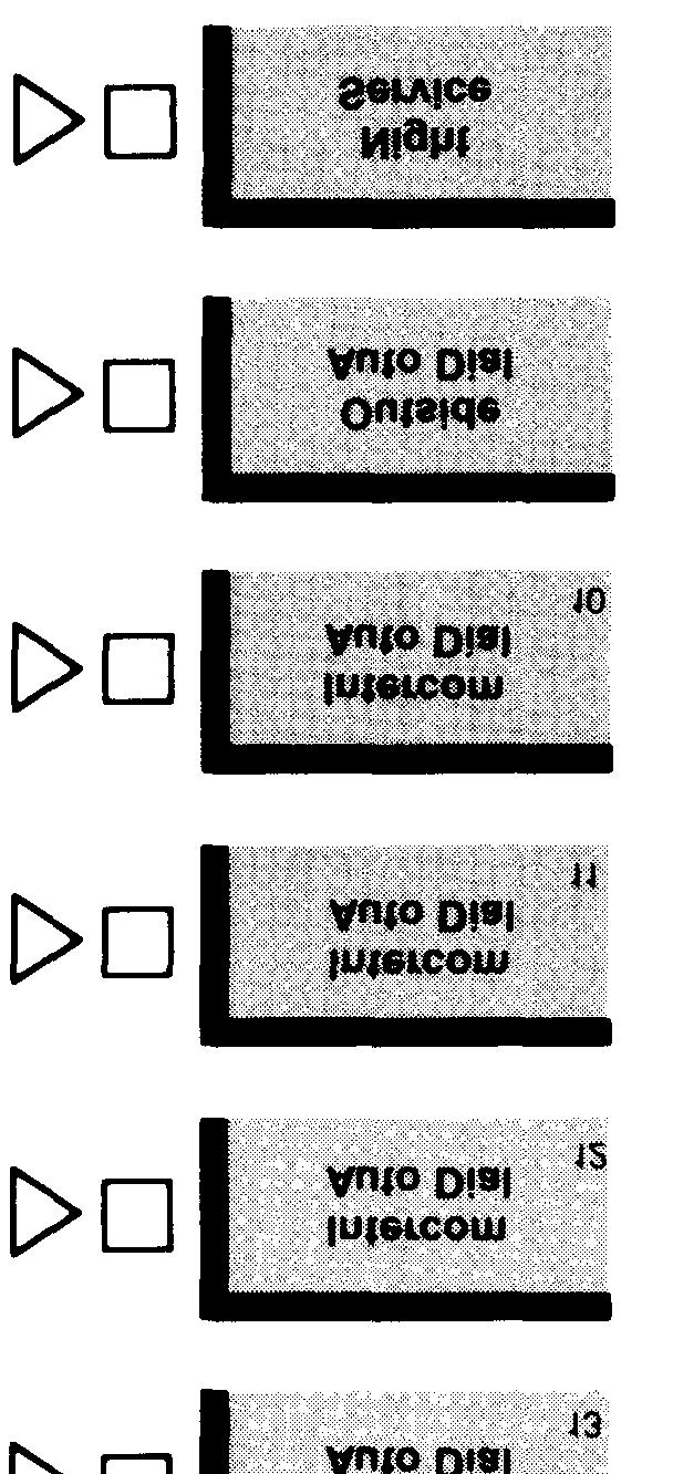
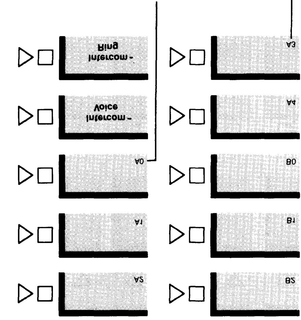

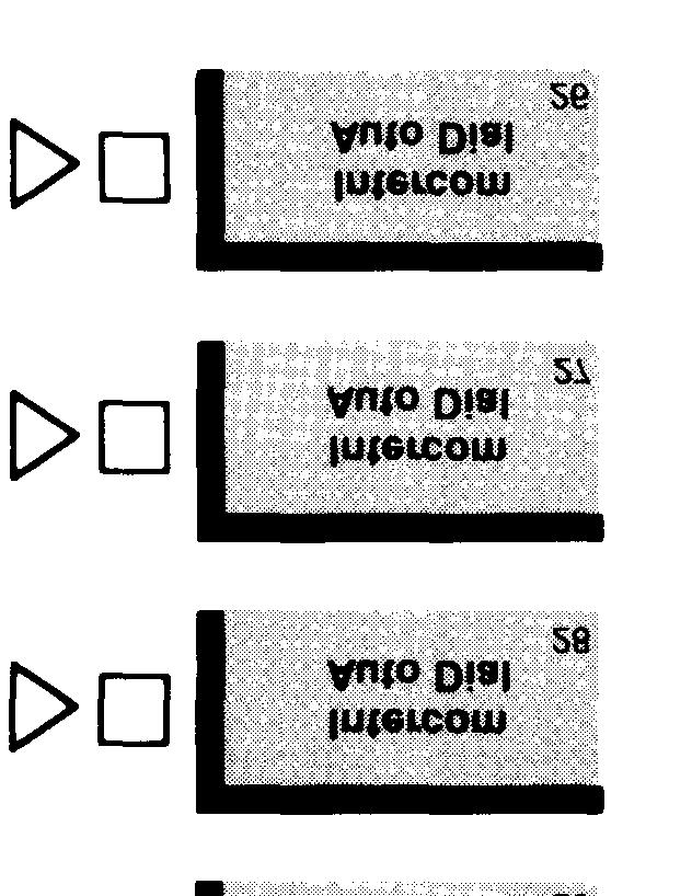
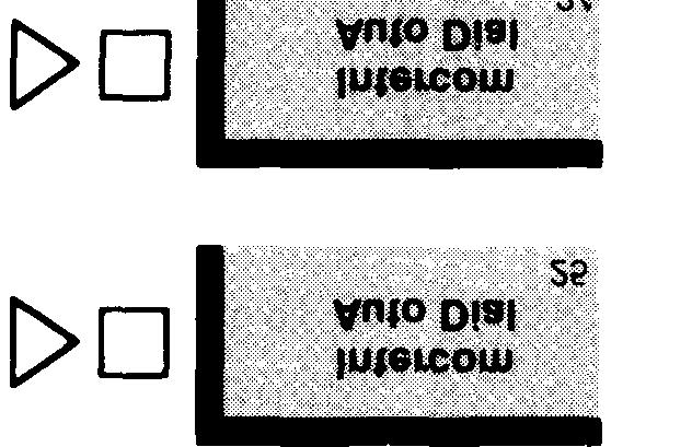

132 Initial Feature Assignments for Administrator/Attendant Console for Small Systems* in Attendant Mode 34-Button Deluxe Voice Terminal Intercom numbers * Control unit jack numbers represent the outside line plugged into that jack. For systems with 8 or fewer lines and 20 or fewer voice terminals switch H on control unit is in the up position. 129
133 130
134 Special Information about 5-Button Voice Terminals Calls can be transferred to a 5-button voice terminal from a line that the voice terminal does not have. You can use either Call Pickup or Line Pickup, depending on whether or not you know which line has the call you want to transfer to the 5-button voice terminal. If you know which line the call is on, place the call on hold, page the person or use his or her Auto Intercom button, and announce the call, for example, Harvey, you have a call from headquarters on line 2. Harvey then uses Line Pickup to take the call. If you don t know which line the call is on, use Call Park to hold the call, and use Loudspeaker Page or Group Page to announce the call, for example, Marie, you have a call from headquarters at intercom 17. Marie then uses Call Pickup to take the call. 131
135 Special Information about Basic Telephones If you have basic telephones connected to an Off-Premises Telephone Interface, a Basic Telephone and Modem Interface, or a Basic Telephone Module, review the following information before you administer the telephones. BASIC TELEPHONES CONNECTED TO AN OFF-PREMISES TELEPHONE INTERFACE (OPTI) OR A BASIC TELEPHONE AND MODEM INTERFACE (BTMI) Follow the procedure below to administer a basic telephone. 1.Enter administration mode by following the boxed instructions on page Assign lines and pools to the intercom number assigned to the OPTI or BTMI by following the instructions in Setting Up Square Systems", page 31, or Setting Up Pooled Systems", page If you want to assign call restrictions to an OPTI or BTMI, follow the instructions in "Assigning Call Restrictions to Voice Terminals", page 46, 4. Leave administration mode by following the boxed instructions on page Use Centralized Voice Terminal Programming or connect a MERLlN voice terminal directly to the control unit voice terminal jack to which you plan to connect the OPTI or BTMI to program the terminal. 6. Since basic telephones may not answer voice-announced intercom calls immediately, you must follow the instructions on page 125 to program Voice Announcement Disable. As a result, voice-announced intercom calls to basic telephones become ringing intercom calls. 7. If you want to change the order in which the system selects available lines, follow the instruction on page 110 to assign an Automatic Line Selection sequence to the telephone, Do not include intercom lines in the sequence. 8. Set programmable line ringing on lines and line pools as preferred. Remove custom features assigned to buttons above the dial pad, 9. Disconnect the voice terminal or leave Centralized Voice Terminal Programming and connect the OPTI or BTMI to the same voice terminal jack. 10. Connect the basic telephone to the OPTI or to the BTMI, 11. If you later add or change the features assigned to a basic telephone, inform the person using the OPTI or BTMI, Users dial the following codes to place calls on a basic telephone connected to an OPTI or BTMI: To get Automatic Line Selection, dial 9. To place a ringing intercom call, dial the 2-digit intercom number. To place a voice-announced intercom call, dial 881 and the 2-digit intercom number. To access the lines or line pools assigned to particular buttons above the dial pad on the voice terminal associated with the user s OPTI or BTMI intercom number, dial the codes shown in the illustrations on the following page. 132


136 Dial Codes to Access Lines, Pools, and Intercom Features Assigned to Voice Terminal Buttons POOLED SYSTEMS WITH DIAL ACCESS TO LINE POOLS POOLED SYSTEMS WITH BUTTON ACCESS TO LINE POOLS 133
MERLIN Communications System
 999-507-137IS MERLIN Communications System Models 1030 and 3070 With Feature Module 2 Administration Manual Table of Contents How to Use This Manual Administration Overview Administering Your System for
AT&T. MERLIN Communications System. Administration Manual: Models 1030 and 3070 With Feature Module 3
 AT&T MERLIN Communications System Administration Manual: Models 1030 and 3070 With Feature Module 3 Table of Contents How to Use This Manual Administration Overview MERLIN System Components The Model 1030
AT&T MERLIN COMMUNICATIONS SYSTEM ATTENDANT S GUIDE: MODELS 1030 AND 3070 WITH FEATURE MODULE 5
 AT&T MERLIN COMMUNICATIONS SYSTEM ATTENDANT S GUIDE: MODELS 1030 AND 3070 WITH FEATURE MODULE 5 MERLIN COMMUNICATIONS SYSTEM ATTENDANT S GUIDE: MODELS 1030 AND 3070 WITH FEATURE MODULE 5 Copyright 1986
AT&T MERLIN COMMUNICATIONS SYSTEM ADMINISTRATION MANUAL: MODELS 206, 410, AND 820 WITH FEATURE PACKAGE 2
 AT&T MERLIN COMMUNICATIONS SYSTEM ADMINISTRATION MANUAL: MODELS 206, 410, AND 820 WITH FEATURE PACKAGE 2 Table of Contents Introduction The Control Unit The Three Types of Cartridges Features and Benefits
AT&T MERLIN COMMUNICATIONS SYSTEM ATTENDANT S GUIDE: MODELS 1030 AND 3070 WITH FEATURE MODULE 3
 AT&T MERLIN COMMUNICATIONS SYSTEM ATTENDANT S GUIDE: MODELS 1030 AND 3070 WITH FEATURE MODULE 3 Table of Contents Getting Started Three Groups of Callers Your Console Small Attendant Console (illustration)
AT&T MERLIN COMMUNICATIONS SYSTEM USER S GUIDE: MODELS 1030 AND 3070 WITH FEATURE MODULE 1
 AT&T MERLIN COMMUNICATIONS SYSTEM TM USER S GUIDE: MODELS 1030 AND 3070 WITH FEATURE MODULE 1 Table of Contents Available Features Key to Symbols Placing and Answering Calls Placing Calls Outside Calls
CIB 3128 Basic Telephone and Modem Interface 2
 CIB 8 Basic Telephone and Modem Interface CIB 8 Comcode 05-656-064 Issue CIB 8 Basic Telephone And Modem Interface The Basic Telephone and Modem Interface (BTMI-) allows you to connect most types of on-premises
AT&T MERLIN II COMMUNICATIONS SYSTEM. Feature Module 2 User s Guide: Basic Touch-Tone and Rotary Telephones
 AT&T MERLIN II COMMUNICATIONS SYSTEM Feature Module 2 User s Guide: Basic Touch-Tone and Rotary Telephones 1988 AT&T All Rights Reserved Printed in USA Issue 2 May, 1988 NOTICE The information in this
MERLIN COMMUNICATIONS SYSTEM ATTENDANT S GUIDE: MODEL 1030 AND 3070 WITH FEATURE MODULE 1
 MERLIN COMMUNICAIONS SYSEM AENDAN S GUIDE: MODEL 1030 AND 3070 WIH FEAURE MODULE 1 able of Contents age age Key to Symbols Attendant Console for a Small System Attendant Console for a Large System Before
MERLINTM COMMUNICATIONS SYSTEM SERVICE AND MAINTENANCE MANUAL: MODELS 1030 AND 3070
 MERLINTM COMMUNICATIONS SYSTEM SERVICE AND MAINTENANCE MANUAL: MODELS 1030 AND 3070 Table of Contents Page Introduction 1 Functional Overview 3 Isolating and Correcting Troubles 21 A. Trouble on One Telephone
Issue 1, June 1988 AT&T AT&T SYSTEM 25 SINGLE-LINE TERMINAL USER GUIDE
 AT&T 555-530-702 Issue 1, June 1988 AT&T SYSTEM 25 SINGLE-LINE TERMINAL USER GUIDE 1988 AT&T All Rights Reserved Printed in USA TO ORDER COPIES OF THIS DOCUMENT REFER TO DOCUMENT NUMBER 555-530-702. Contact:
DEFINITY Communications
 DEFINITY Communications System Generic 2 and System 85 7410 Plus Voice Terminal User's Guide Contents Your 7410 Plus Voice Terminal A Quick Look at the Features How to Use the Features Abbreviated Dialing
AT&T System 25. Multiline Telephone. User Guide
 AT&T System 25 Multiline Telephone User Guide 1989 AT&T All Rights Reserved Printed in USA TO ORDER COPIES OF THIS DOCUMENT REFER TO DOCUMENT NUMBER 555-540-703. Contact: Your AT&T sales representative,
Advanced Codes Settings for the H650IVN
 Advanced Codes Settings for the H650IVN Special Notes: Voice Mail- 30 minutes of record time. When the voice mail becomes full with recorded messages, new messages will not overwrite or erase stored messages.
AT&T. DEFINITY Communications. ISDN 7505, 7506, and 7507 Terminals User's Guide. System Generic 2
 AT&T DEFINITY Communications System Generic 2 ISDN 7505, 7506, and 7507 Terminals User's Guide NOTICE While reasonable efforts were made to ensure that the information in this document was complete and
AT&T System 25 Single-Line Telephone
 555-540-702 Issue 1 1989 AT&T System 25 Single-Line Telephone User Guide 1989 AT&T All Rights Reserved Printed in USA TO ORDER COPIES OF THIS DOCUMENT REFER TO DOCUMENT NUMBER 555-540-702. Contact: Your
AT&T System 25. Attendant Console. Direct Trunk. User Guide
 AT&T System 25 Direct Trunk Attendant Console. User Guide 1989 AT&T All Rights Reserved Printed in USA TO ORDER COPIES OF THIS DOCUMENT REFER TO DOCUMENT NUMBER 555-540-701. Contact: Your AT&T sales representative,
Four-Line Intercom/ Speakerphone 954
 1 USER S MANUAL Part 2 Four-Line Intercom/ Speakerphone 954 Please also read Part 1 Important Product Information AT&T and the globe symbol are registered trademarks of AT&T Corp. licensed to Advanced
AT&T AT&T SYSTEM 25 DIRECT TRUNK ATTENDANT CONSOLE USER GUIDE Issue 1, June 1988
 AT&T 555-530-701 Issue 1, June 1988 AT&T SYSTEM 25 DIRECT TRUNK ATTENDANT CONSOLE USER GUIDE 1988 AT&T All Rights Reserved Printed in USA TO ORDER COPIES OF THIS DOCUMENT REFER TO DOCUMENT NUMBER 555-530-701.
CentraNet CustoPAK USER GUIDE. Telephone Number. Verizon Telephone Number. Switch Type: GTD-5 5ESS DMS 100 DMS 10
 CentraNet CustoPAK USER GUIDE Telephone Number Verizon Telephone Number Switch Type: GTD-5 5ESS DMS 100 DMS 10 INSIDE FRONT COVER Thank You for Selecting Verizon CentraNet CustoPAK Service. 1 Table of
Issue 1, June 1987 AT&T SYSTEM 25 SWITCHED LOOP ATTENDANT CONSOLE USER GUIDE
 555-520-706 Issue 1, June 1987 AT&T SYSTEM 25 SWITCHED LOOP ATTENDANT CONSOLE USER GUIDE 1987 AT&T All Rights Reserved Printed in USA TO ORDER COPIES OF THIS DOCUMENT REFER TO DOCUMENT NUMBER 555-520-706.
Two-Line Speakerphone with Caller ID/Call Waiting 992
 0992_CIB_1ATT_FINAL_022105 2/22/04 4:46 PM Page II User's Manual Part 2 Two-Line Speakerphone with Caller ID/Call Waiting 992 In case of difficulty, visit our Service Center at www.telephones.att.com or
AT&T. DEFINITY Communications. 7406BIS Voice Terminal User's Guide. and System 85. System Generic 2
 AT&T DEFINITY Communications System Generic 2 and System 85 7406BIS Voice Terminal User's Guide NOTICE While reasonable efforts were made to ensure that the information in this document was complete and
Starplus II non-speakerphone Guide
 Starplus II non-speakerphone Guide ANSWERING a Call While the phone is ringing you will hear the ringer and see the message light flashing. Lift the handset to answer the call. BASIC DIALING Campus Calls:
Impact Attendant for Windows PC Attendant Console User s Guide For The DXP, DXP Plus and FX Series Digital Communications Systems
 Impact Attendant for Windows Impact Attendant for Windows PC Attendant Console User s Guide For The DXP, DXP Plus and FX Series Digital Communications Systems Comdial strives to design the features in
Basic phone operation
 Telephone operation Basic phone operation DO NOT DISTURB When you activate the Do Not Disturb (DND) function, you will not hear paging tones, voice paging, or incoming call rings. Instead, the LINE light
AT&T. Installation, Administration, and Maintenance Manual COMMUNICATIONS SYSTEM
 AT&T 518-600-016 MERLIN II COMMUNICATIONS SYSTEM Installation, Administration, and Maintenance Manual 1990 AT&T Issue 2 All Rights Reserved January, 1990 Printed in USA NOTICE The information in this document
Avaya IP Office Phone Manual
 Avaya IP Office Phone Manual Contents 1 PHONES... 3 1.1 Overview of the 5402... 3 1.2 Overview of the 5410... 5 1.3 Overview of the 5420... 7 1.4 Overview of the 1403 / 1603... 9 1.5 Overview of the 1408
Keystation Feature Card
 Keystation Feature Card Using Commander NT features To use a Commander NT feature Programming memory keys 1. Press ƒ, and enter the desired feature code on the dial pad. OR Press the programmed memory
AT&T. DEFINITY Communications System. 8503T Voice Terminal User's Guide. Generic 1 and Generic 3
 AT&T DEFINITY Communications System Generic 1 and Generic 3 8503T Voice Terminal User's Guide NOTICE While reasonable efforts were made to ensure that the information in this document was complete and
900 MHz Digital Two-Line Cordless Speakerphone with Answering System 9452 with Caller ID/Call Waiting
 USER S MANUAL Part 2 900 MHz Digital Two-Line Cordless Speakerphone with Answering System 9452 with Caller ID/Call Waiting Please also read Part 1 Important Product Information AT&T and the globe symbol
Centrex User Guide. (Version 2.0)
") Centrex User Guide (Version 2.0) 1. Welcome to CENTREX Welcome to CENTREX! We know you will be pleased with your new telephone service. You have selected a telecommunications system designed with you in
Centrex User Guide (Version 2.0) 1. Welcome to CENTREX Welcome to CENTREX! We know you will be pleased with your new telephone service. You have selected a telecommunications system designed with you in
DEFINITY Communications
 AT&T DEFINITY Communications System Generic 2 and System 85 7406 Plus Voice Terminal User's Guide NOTICE While reasonable efforts were made to ensure that the information in this document was complete
9417CW Installation and User Guide
 9417CW Installation and User Guide 9417CW Telephone Important Tips Wait for at least two rings to allow the phone to identify a caller and display the caller s name and/or number. You will have to subscribe
Contents. Section 1 Overview 1. Section 2 Setting up your System 13
 Contents Section 1 Overview 1 Introduction 1 Installing Your System 2 Bizfon Customer Care 2 Voice Vault Card Option 2 Arranging for Telephone Company Services 3 Overview of Initial Bizfon Settings 4 Bizfon
Call Forwarding Busy Line Fixed Allows you to redirect calls to another telephone number when your telephone line is busy.
 Calling Features User Guide Call Forwarding Busy Line Fixed Allows you to redirect calls to another telephone number when your telephone line is busy. 2. Press *90 3. When you hear the interrupted dial
Issue 1, June 1988 AT&T AT&T SYSTEM 25 SWITCHED LOOP ATTENDANT CONSOLE USER GUIDE
 AT&T 555-530-706 Issue 1, June 1988 AT&T SYSTEM 25 SWITCHED LOOP ATTENDANT CONSOLE USER GUIDE 1988 AT&T All Rights Reserved Printed in USA TO ORDER COPIES OF THIS DOCUMENT REFER TO DOCUMENT NUMBER 555-530-706.
DEFINITY Enterprise Communications Server (ECS) Release Voice Terminal User s Guide
 Release Voice Terminal User s Guide") DEFINITY Enterprise Communications Server (ECS) Release 5 8403 Voice Terminal User s Guide 555-230-761 Comcode 107983496 Issue 2 March 1997 NOTICE While reasonable efforts were made to ensure that the
DEFINITY Enterprise Communications Server (ECS) Release 5 8403 Voice Terminal User s Guide 555-230-761 Comcode 107983496 Issue 2 March 1997 NOTICE While reasonable efforts were made to ensure that the
PROTEGÉ 616 Digital Hybrid Key System
 PROTEGÉ 616 Digital Hybrid Key System Keyset User Guide with display Mat Code 699050 SPRINT PRODUCTS GROUP HAS MADE EVERY EFFORT TO ENSURE THE TECHNICAL ACCURACY OF THIS GUIDE. FEATURES AND TECHNICAL DATA
SAMSUNG HANDSET USER GUIDE FOR DS-5007S / DS-5014S / DS-5038S / DS-5014D / DS-5021D ITP-5107 / ITP-5114D / ITP5121D
 SAMSUNG HANDSET USER GUIDE FOR DS-5007S / DS-5014S / DS-5038S / DS-5014D / DS-5021D ITP-5107 / ITP-5114D / ITP5121D FOR TECHNICAL TIPS PLEASE VISIT OUR WEBSITE www.conversetelecom.com 2 Table of Contents
Custom Calling Features
 How To Use Custom Services For Bloomer, Canton, New Auburn-Long Lake subscribers Notice: Please contact your business office to obtain these calling features: Call Waiting Allows you to never have to miss
Polycom Soundpoint 650 IP Phone User Guide
 20 19 18 17 16 1 2 15 14 13 12 This guide will help you to understand and operate your new IP Phone. Please print this guide and keep it handy! 3 11 For additional information go to: http://www.bullseyetelecom.com/learning-center
6402 Voice Terminal User s manual. DEFINITY G3 - Release 6.3 or later
 6402 Voice Terminal User s manual DEFINITY G3 - Release 6.3 or later 555-230-757 Issue 1, July 2000 Copyright 2000 Lucent Technologies All rights reserved Notice While reasonable efforts were made to ensure
AT&T. MERLIN Plus COMMUNICATIONS SYSTEM. Release 2 Installation Manual
 AT&T MERLIN Plus COMMUNICATIONS SYSTEM Release 2 Installation Manual 1988 AT&T Issue 1 All Rights Reserved August, 1988 Printed in USA NOTICE The information in this document is subject to change without
NEC NEAX 2000 IPS USER GUIDE
 NEC NEAX 2000 IPS USER GUIDE Phone Features and Functions ANSWERING A CALL: 1.) To answer a ringing call, lift the handset or press . PLACING AN INTERNAL CALL 1.) Lift the handset or press .
About Your Telephone
 About Your Telephone The 6402D is a single-line telephone with conventional touch-tone dialing and a 16-character display. To familiarize yourself with the buttons and features on your telephone, refer
Table of Contents Console Operations
 555-231-735 Issue 1 March, 1996 Table of Contents Console Operations Graphics AT&T Blank Page Contents Table of Contents i Console Operations 1 About This Book 1 Assumptions 2 Conventions 2 Related Documents
M6310 Featurephone. User Guide
 M6310 Featurephone User Guide Introduction The M6310 Featurephone is a practical and convenient way to use a wide range of business telephone features, including Call Forward, Conference Calling, and
Quick start guide. MS Line Small Business Deskset
 Quick start guide MS2015 4-Line Small Business Deskset Parts checklist Your telephone package contains the following items. Save your sales receipt and original packaging in the event warranty service
AT&T CLASSIC MAIL. Voice Messaging System Mailbox User Guide
 AT&T CLASSIC MAIL Voice Messaging System Mailbox User Guide Copyright 1993 All Rights Reserved AT&T 585-321-101 Issue 1 December 1993 Notice Every effort was made to ensure that the information in this
Avaya Campus PBX MICHIGAN STATE UNIVERSITY. Telecommunication Systems. Avaya 2420 User Guide
 Avaya Campus PBX MICHIGAN STATE UNIVERSITY Telecommunication Systems Avaya 2420 User Guide MICHIGAN STATE UNIVERSITY Avaya 2420 Telephone User Guide Michigan State University Telecommunication Systems
Aastra Model 6731i IP Phone
 Aastra Model 6731i IP Phone User Guide Release 3.2 41-001387-00 Rev 00 01.2011 Making Calls Making Calls This section describes ways to make calls on your 6731i phone, using your handset, speakerphone
Frequently Asked Questions
 Serene CL-60A Amplified Talking CID Cordless Phone with Slow-Play, Amplified Answering Machine Frequently Asked Questions Q: Base Charging Indicator is not on when handset is placed on the base. A: Move
Quick start guide Line small business system with speakerphone
 Quick start guide 1040 4-Line small business system with speakerphone This quick start guide provides basic instructions For additional installation options and complete instructions that enable you to
2.4 GHz Cordless Telephone Answering System 2325/2365 with Caller ID/Call Waiting
 USER S MANUAL Part 2 2.4 GHz Cordless Telephone Answering System 2325/2365 with Caller ID/Call Waiting Please also read Part 1 Important Product Information 2002 Advanced American Telephones. All Rights
AT&T. DEFINITY Communications System. ISDN 8510T Voice Terminal User's Guide. Generic 1 and Generic 3
 AT&T DEFINITY Communications System Generic 1 and Generic 3 ISDN 8510T Voice Terminal User's Guide NOTICE While reasonable efforts were made to ensure that the information in this document was complete
Classic Mail Design Package
 Merlin 1030/3070 Classic Mail Design Package For Release 1.6 Site Survey Record Merlin System Data Procedure: Record Merlin system information on the Site Survey forms. Requirements: Merlin 1030 Feature
DEFINITY Communications System
 AT&T DEFINITY Communications System Generic and Generic and System 75 7444 Voice Terminal User's Guide NOTICE While reasonable efforts were made to ensure that the information in this document was complete
Quick start guide Line small business system with caller ID/call waiting and speakerphone
 Quick start guide 1070 4-Line small business system with caller ID/call waiting and speakerphone This quick start guide provides basic instructions. For additional installation options and complete instructions
Enterprise Edge Telephone Feature Card
 Enterprise Edge Telephone Feature Card 2000 Nortel Networks P0908931 Issue 03 Using Enterprise Edge features Using an Enterprise Edge feature Programming memory buttons 1. Press ƒ and enter the desired
M7324 Telephone User Card
 M7324 Telephone User Card Your Norstar M7324 telephone Memory and line buttons are buttons with indicators for one touch dialing, feature operation or line access. Display shows the time, date, call information
Enterprise Edge 2.0 Feature Programming Telephone Guide
 Enterprise Edge 2.0 Feature Programming Telephone Guide 1-800-4 NORTEL www.nortelnetworks.com 2000 Nortel Networks P0911589 Issue 03 Contents Chapter 1 Getting Started 11 Using this guide 11 Before you
TABLE OF CONTENTS Introduction: Default Operation and Remote Programming Programming Receptionist Extensions Installing CallExtend
 TABLE OF CONTENTS Introduction: Default Operation and Remote Programming... 1 CallExtend s Default Settings... 1 Resetting CallExtend to the Default Settings... 3 Remote Programming... 4 Installing CallExtend...
Getting Started 3. Using this Guide 3 Connecting Your Phone 4
 Table of Contents Getting Started 3 Using this Guide 3 Connecting Your Phone 4 Adjusting the Footstand / Handset Rest 5 Signing In to Your Phone 5 Choosing the Proper Headset 5 An Overview of Your Phone
2.4 GHz 2-Line Corded/Cordless Answering System 2462 with Caller ID/Call Waiting
 2462_00_1 ATT CIB 1/28 1/28/02 9:52 AM Page ii 1 USER S MANUAL Part 2 2.4 GHz 2-Line Corded/Cordless Answering System 2462 with Caller ID/Call Waiting DRAFT 1/28/02 Please also read Part 1 Important Product
AT&T. PARTNER II Centrex Communications System Release 1 Installation and Use
 AT&T PARTNER II Centrex Communications System Release 1 Installation and Use Copyright 1991 AT&T All Rights Reserved Printed in U.S.A. AT&T 518-455-330 Issue 1 November 1991 Notice Every effort was made
MERLIN LEGEND Communications System Release 2.0 MLC-5 Cordless Telephone Quick Reference
 MERLIN LEGEND Communications System Release 2.0 MLC-5 Cordless Telephone Quick Reference 1. 2. 3. 4. 5. 6. 7. 8. 9. 10. 11. 12. 13. 14. 15. 16. 17. System Speed Dialing Account Codes List Most Often Used-Codes
Industry Standard Telephone (IST) Station User s Guide. DXP, DXP Plus, and FX Digital Telephone Systems
 Station User s Guide. DXP, DXP Plus, and FX Digital Telephone Systems") Industry Standard Telephone (IST) Station User s Guide DXP, DXP Plus, and FX Digital Telephone Systems This user s guide applies to industry standard single-line telephones such as the model 2500-** when
Industry Standard Telephone (IST) Station User s Guide DXP, DXP Plus, and FX Digital Telephone Systems This user s guide applies to industry standard single-line telephones such as the model 2500-** when
VBX Feature Guide. 1 Introduction. List of Abbreviations. About this Feature Guide. AA - Automated Attendant. COS - Class of Service
 VBX Feature Guide 2 VBX Feature Guide 1 Introduction About this Feature Guide The Feature Guide is designed to serve as an overall reference describing the features of the ECN Virtual PBX (VBX) It explains
System 24 System 48 Suite 64
 The following feature list is a combination of features for PCS Digital Telephone systems. Therefore, some of the descriptions combine both systems, so be sure to double check the Installation and Maintenance
DXP, DXP Plus, and FX Series
 DXP, DXP Plus, and FX Series Digital Communications Systems Large Screen Display Speakerphone Station User s Guide User Guide GCA70349.05 06/03 Printed in U.S.A. This user s guide is for the following
AT&T. ZoneMate 3 Service Manual. PagePac 20 Voice Paging System. MERLIN CS Connection And Operation
 AT&T PagePac 20 Voice Paging System ZoneMate 3 Service Manual MERLIN CS Connection And Operation ZoneMate 3 Service Manual For PagePac 20 Voice Paging System and Merlin* Communications System Models 1030
Voice Terminal User s manual. DEFINITY G3 - Release 6.3 or later
 6408-6416 - 6424 Voice Terminal User s manual DEFINITY G3 - Release 6.3 or later 555-230-758 Issue 1, July 2000 Copyright 2000 Lucent Technologies All rights reserved Notice While reasonable efforts were
AT&T. AT&T System 25. Switched Loop Attendant Console. User Guide
 AT&T AT&T System 25 Switched Loop Attendant Console User Guide 1989 AT&T All Rights Reserved Printed in USA TO ORDER COPIES OF THIS DOCUMENT REFER TO DOCUMENT NUMBER 555-540-706. Contact: Your AT&T sales
User s manual. ML17929 Two-line corded telephone with caller ID/call waiting
 User s manual ML17929 Two-line corded telephone with caller ID/call waiting Congratulations on purchasing your new AT&T product. Before using this AT&T product, please read Important safety information
CORTELCO 2740 Four-Line Telephone / Caller ID / Type II Set Instruction Manual
 CORTELCO 2740 Four-Line Telephone / Caller ID / Type II Set Instruction Manual 1 Table of Contents Why VoiceManager SM with Cortelco Phones?... 2 Cortelco 2740 Telephone Set Main Features... 3 Telephone
IP Office Basic Edition Quick Mode T7100 Phone User Guide
 Quick Mode T7100 Phone User Guide - Issue 4a - (03 October 2011) 2011 AVAYA All Rights Reserved. Notices While reasonable efforts have been made to ensure that the information in this document is complete
DIGITAL TELEPHONE USER GUIDE
 DIGITAL TELEPHONE USER GUIDE Release 1 COPYRIGHT 1993 TOSHIBA AMERICA INFORMATION SYSTEMS, INC. All rights reserved. No part of this manual may be reproduced in any form or by any means graphic, electronic,
For Users on Resilient 3300 ICP Systems 3. Don't cradle the handset! 3 Protect your hearing 4 Angle the phone for easier viewing 4
 USER GUIDE 3300 ICP - 7.0 Contents ABOUT YOUR PHONE 1 For Users on Resilient 3300 ICP Systems 3 TIPS FOR YOUR COMFORT AND SAFETY 3 Don't cradle the handset! 3 Protect your hearing 4 Angle the phone for
AT&T. DEFINITY Communications System. Generic 2 and System Voice Terminal User's Guide
 AT&T DEFINITY Communications System Generic 2 and System 85 8410 Voice Terminal User's Guide NOTICE While reasonable efforts were made to ensure that the information in this document was complete and accurate
TC-308, TC-616 TC-308-VM, TC-616-VM TC-616-NHR, TC-616-NHR-VM
 TeleCraft Hybrid Key Telephone Communication System User s Manual Version 6.02 Models: TC-308, TC-616 TC-308-VM, TC-616-VM TC-616-NHR, TC-616-NHR-VM About This Manual We wrote this manual with you, the
PCS 60 User Manual. Version 3.2. April 2009 Part No. DOC-MN-PCS60-00
 Version 3.2 April 2009 Part No. DOC-MN-PCS60-00 Document No. 005 Version No. V3.2/0409/4 Copyright SpliceCom Ltd SpliceCom Ltd The Hall Business Centre, Berry Lane Chorleywood, Herts WD3 5EX Tel: 01923
6408+, 6408D+, 6416D+, 6416D+M, 6424D+, and 6424D+M Telephones User s Guide
 6408+, 6408D+, 6416D+, 6416D+M, 6424D+, and 6424D+M Telephones User s Guide Contents 6400 Series Multi-line Telephones................... 5 Using the Softkeys................................ 8 Using the
AT&T. PARTNER Plus Communications System Release 3. Programming and Use
 AT&T PARTNER Plus Communications System Release 3 Programming and Use Copyright 1992 AT&T All Rights Reserved Printed in U.S.A. AT&T 518-455-212 Issue 1 June 1992 Notice Every effort was made to ensure
Quick start guide Line small business system with digital answering system and caller ID/call waiting
 Quick start guide 1080 4-Line small business system with digital answering system and caller ID/call waiting This quick start guide provides basic instructions. For additional installation options and
Caller ID Telephone 962
 1 USER S MANUAL Part 2 Caller ID Telephone 962 Please also read Part 1 Important Product Information AT&T and the globe symbol are registered trademarks of AT&T Corp. licensed to Advanced American Telephones.
Custom Calling Services
 CUSTOM CALLING SERVICES ARE AVAILABLE IN YOUR AREA. THERE WILL BE AN ADDITIONAL MONTHLY CHARGE FOR EACH SERVICE. This group of Custom Calling Features can put your phone to work for you. By simply dialing
AT&T Unified Communications Services
 AT&T Unified Communications Services UC Voice User s Guide For End Users V1.2 October, 2015 Disclaimer The contents of the document may be revised by AT&T at any time without notice. Please consult the
Compact ICS Telephone Feature Card
 Compact ICS Telephone Feature Card Buttons This card shows the Business Series Terminals buttons. The table below shows which buttons to use on the different types of Nortel Networks telephones. Button
Frequently Asked Questions
 Serene CL-60 Big Button Amplified Talking CID Cordless Phone W/ Display Screen Frequently Asked Questions Q: How can I turn off the "talking" voice? A: Just set the "talking" selection switch to Off in
CALNET 3: AT&T Voice DNA Polycom SoundPoint IP 650 / 670
 CALNET 3: AT&T Voice DNA Polycom SoundPoint IP 650 / 670 Version 1.4 2018 AT&T Intellectual Property. All rights reserved. AT&T, Globe logo, Mobilizing Your World and DIRECTV are registered trademarks
Tapeless Digital Answering System with Time/Day Part 2
 2 Tapeless Digital Answering System with Time/Day 1715 Fold open this manual for information about this telephone's installation and operation. Please read Part 1 Important Product Information, included
3300 IP Communications Platform
 MITEL 3300 IP Communications Platform 5304 IP Phone User Guide NOTICE The information contained in this document is believed to be accurate in all respects but is not warranted by Mitel Networks Corporation
Digital Telephone System. Speakerphone and Monitor Telephone System Reference Guide
 R Digital Telephone System Speakerphone and Monitor Telephone System Reference Guide GHI PRS 1 ABC2 4 7 JKL TUV OPER 5 MNO6 8 WXY9 0 DEF 3 # SPKR T/C MUTE HOLD TAP ITCM unisyn01.cdr This user guide is
Automated Attendant and Voice Mail System
 LX Automated Attendant and Voice Mail System User s Guide Nothing contained in this guide shall be deemed to be, and this guide does not constitute, a warranty of, or representation with respect to, any
changing the way you share your world Call Management Services User Guide
 changing the way you share your world Call Management Services User Guide 1 800 360-8555 www.northerntel.ca Quick reference NorthernTel Call Management Services - Important Codes Service Activation Cancellation
9516CW Installation and User Guide
 9516CW Installation and User Guide 9516CW Important Tips Wait for at least two rings to allow the phone to identify a caller and display the caller s name and/or number. You will have to subscribe to a
VBX Feature Guide. 1 Introduction. List of Abbreviations. About this Feature Guide. AA - Automated Attendant. COS - Class of Service
 VBX Feature Guide 2 VBX Feature Guide 1 Introduction About this Feature Guide The Feature Guide is designed to serve as an overall reference describing the features of the ECN Virtual PBX (VBX) It explains
User Guide: Panasonic KX-UT113
 User Guide: Panasonic KX-UT113 User Guide Contents: User Guide Contents:... 2 KX-UT113 Button Diagram... 3 Telephone Feature Overview... 4 KX-UT113 Features... 4 Reading the Display... 4 How to Use your
STANDARD TELEPHONE USER GUIDE
 STANDARD TELEPHONE USER GUIDE SAMSUNG idcs 16 March 2005 Samsung Telecommunications America reserves the right without prior notice to revise information in this guide for any reason. Samsung Telecommunications