UTAH-100/UDS XY-Panel. Setup and Operation Guide
|
|
|
- Allen Hutchinson
- 5 years ago
- Views:
Transcription
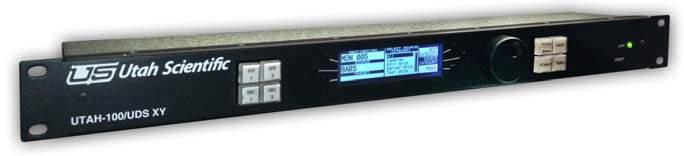

1 UTAH-100/UDS XY-Panel Setup and Operation Guide
2 UTAH 100/UDS XY Control Panel Document Number: Document Version: 1.0 Date: January 28, 2015 Printed in U.S.A. Copyrights and Trademarks 2015 Utah Scientific, Inc., All rights reserved. Any use or reproduction of this guide s contents without the prior written consent of Utah Scientific, Inc. is strictly prohibited. UTAH 100 is a trademarks of Utah Scientific, Inc. Windows, Windows 2000 and Windows NT and XP are registered trademarks of Microsoft Corporation. All other product names and any registered or unregistered trademarks mentioned in this guide are used for identification purposes only and remain the exclusive property of their respective owners. Notice Information contained in this guide is subject to change without notice or obligation. While every effort has been made to ensure that the information is accurate as of the publication date, Utah Scientific, Inc. assumes no liability for errors or omissions. In addition, Utah Scientific, Inc. assumes no responsibility for damages resulting from the use of this guide. FCC Compliance (USA) and Digital Equipment Compliance (Canada) This equipment has been tested and found to comply with the limits for a Class A, digital device, pursuant to Part 15, Subpart B of the FCC Rules and the Canadian EMC Requirement (ICES-003). These limits are designed to provide reasonable protection against harmful interference when the equipment is operated in a commercial environment. This equipment generates, uses, and can radiate radio frequency energy and, if not installed and used in accordance with the instruction manual, may cause harmful interference to radio communications. Operation of this equipment in a residential area is likely to cause harmful interference, in which case, the user will be required to correct the interference at their own expense. Shielded cables must be used to ensure compliance with the FCC Class A limits. ii
3 Declaration of Conformity Utah Scientific, Inc Wiley Post Way, Suite 150 Salt Lake City, Utah U.S.A. We declare our sole responsibility that the UTAH-100/UDS Digital Routing Switcher is in conformance with the following standards: Emission EN55022:1994+A1&A2 Immunity EN55024:1998 EN EN Safety IEC :2001 /EN :2001 Following the provisions of the Directive(s) of the Council of the European Union: EMC Directive 89/336/EED Low Voltage Electrical Directive 72/23/EEC Utah Scientific, Inc. hereby declares that the product specified above conforms to the above Directive(s) and Standard(s). Section 1 iii
4 Important Safeguards and Notices This section provides important safety guidelines for the Operator and Service Personnel. Specific warnings and cautions are found throughout the guide where they apply, but may not appear here. Please read and follow the important safety information, specifically those instructions related to risk of fire, electric shock, or injury to persons. Safety Symbols Hazardous Voltage symbol Caution symbol. The product is marked with this symbol when it is necessary to refer to the manual to prevent damage to the product. Warnings Please observe the following important warnings: Any instructions in this guide that require opening the chassis, changing a power supply, or removing a board, should be performed by qualified personnel only. To reduce the risk of electric shock, do not perform any service unless you are qualified to do so. Heed all warnings on the unit and in the operating instructions. Do not use this product in or near water. Disconnect AC power before installing any options or servicing the unit unless instructed to do so by this manual. This product is grounded through the power cord ground conductor. To avoid electric shock, plug the power cord into a properly wired receptacle before connecting the product inputs or outputs. Route power cords and other cables so they won t be damaged. The AC receptacle (socket) should be located near the equipment and be easily accessible. Disconnect power before cleaning. Do not use any liquid or aerosol cleaner - use only a damp cloth. iv
5 Dangerous voltages exist at several points in this product. To avoid personal injury, do not touch exposed conductors and components while power is on. Do not insert anything into either of the systems two-power supply cavities with power connected. Do not wear hand jewelry or watches when troubleshooting high current circuits, such as power supplies. During installation, do not use the door handles or front panels to lift the equipment as they may open abruptly and injure you. To avoid fire hazard when replacing fuses, use only the specified correct type, voltage and current rating as referenced in the appropriate parts list for this product. Always refer fuse replacement to qualified service personnel. Have qualified personnel perform safety checks after any service. Cautions Please observe the following important cautions: When installing this equipment do not install power cords to building surfaces. To prevent damage when replacing fuses, locate and correct the problem that caused the fuse to blow, before reconnecting power. Use only specified replacement parts Section 1 v
6 Company Information Utah Scientific, Incorporated 4750 Wiley Post Way, Suite 150 Salt Lake City, Utah U.S.A. Telephone: +1 (801) FAX: +1 (801) Technical Services (voice): +1 (800) Technical Services (FAX): +1 (801) General Information: -Technical Services: World Wide Web: After Hours Emergency: +1 (800) Follow the menu instructions for Emergency Service. vi
7 Warranty Policies Hardware Warranty Utah Scientific, Inc. warrants to the original purchaser that the Utah Scientific hardware is free from defects in materials and workmanship and will perform substantially in accordance with the accompanying written materials under normal use and service for a period of two (2), five (5), or ten (10) years from the date of shipment. Any implied warranties on hardware are limited to the above three warranty periods (depending on purchase). Some states/jurisdictions do not allow limitations on duration of an implied warranty, so the above limitation may not apply to certain specific purchasers. Software Warranty Utah Scientific warrants that the software will perform substantially in accordance with the accompanying written materials for a period of one (1) year from the date of shipment. Customer Remedies For the first one (1) year after purchase of the software and the first two (2), five (5), or ten (10) years after the date of purchase of the hardware, Utah Scientific s and its suppliers entire liability and purchaser s exclusive remedy shall be, at Utah Scientific s option, either: Return of the price paid, or Repair or replacement of the software or hardware that does not meet the above warranties and is returned to Utah Scientific under the returned materials authorization (RMA) process with freight and forwarding charges paid. After the initial warranty periods, purchaser s exclusive remedy is the repair or replacement of the hardware upon payment of a fixed fee to cover handling and service costs based on Utah Scientific s then-current price schedule. The above warranties are void if failure of the software or hardware has resulted from an accident, abuse, or misapplication. Any replacement software or hardware will be warranted for the remainder of the original warranty period or thirty (30) days, whichever is longer. Section 1 vii
8 No other warranties. To the maximum extent permitted by applicable law, Utah Scientific and its suppliers disclaim all other warranties, either express or implied, including, but not limited to implied warranties of merchantability and fitness for a particular purpose, with regard to the software, the accompanying written materials, and any accompanying hardware. This limited warranty gives the purchaser specific legal rights. These rights may vary in certain states/jurisdictions. No liability for consequential damages. To the maximum extent permitted by applicable law, in no event shall Utah Scientific or its suppliers be liable for any damages whatsoever (including without limitation, damages for loss of business profits, business interruption, loss of business information, or any other pecuniary loss) arising out of the use of or inability to use Utah Scientific products, even if Utah Scientific has been advised of the possibility of such damages. Because some states/jurisdictions do not allow the exclusion or limitation of liability for consequential or incidental damages, the above limitation may not apply in those circumstances. viii
9 Table of Contents Section 1 Panel Operation Introduction System Setup Requirements The UTAH-100/UDS XY Panel Home Options Source Track Button Auto Source Preset Auto Destination Select Knob Clockwise Knob Take Network Setup Network Summary Panel Info Additional Notes - Review Operation / Making a Take Panel Operation The Link Light Panel Buttons Source and Destination Lock Browser Operation General Overview Radio Buttons System Source Categories Destination Categories button Encoding Enabling Function Parameters Save and Program Table of Contents 1
10 2 UTAH-100/UDS Setup & Operations Guide
11 Introduction Section 1 Section 1 Panel Operation Introduction This guide covers the setup and operational detail of the UTAH-100/UDS XY panel, including fixed panel operation and the accompanying browser utility. System Setup Requirements Windows operating system 7 Java 7.07 or newer Internet Explorer, Firefox, or Chrome Ethernet connection All UDS devices - PC, Router, and Panel - connect over Ethernet on a house network, or within a stand-alone (direct) mode. The system will provide default IP address during setup, or you can use unique IP addresses if required within your operation. Section 1 1-1
. Figure 1-1.")


12 Panel Operation The UTAH-100/UDS XY Panel Home Press the Home button to take the panel to the main menu selection (below). Figure 1-1. Home button and screen display Using the scroll wheel, rotate to Options and press the wheel to select. Options There are five options available for modification from this screen; Source Track Button, Auto Source Preset, Auto Destination Select, Knob clockwise or counter-clockwise control, and Knob Take (on or off). Highlight the option to select, then press the knob to make a change, or press the Enable/Disable button to the right to make a change. Note: You must press the Save button to complete the change. Figure 1-2. XY Panel Options 1-2 System Setup

13 The UTAH-100/UDS XY Panel Source Track Button Source Tracking allows automatic Takes when enabled. The current Tracking status will display at the location illustrated below. When enabled, takes will occur immediately whenever a new Source is highlighted by scrolling. Takes are simultaneous, without any Preset or separate Take activation. Section 1 Figure 1-3. Track button - enabled Use the Track button to toggle tracking on or off. Note that while in Tracking mode, the last Preset remains listed (bottom left within the display), allowing for an immediate return to the last preset by pressing the Take button. Disabling Source tracking will turn the track item off and the Sources will then work in a Preset/Take mode only. In this mode you will scroll to the desired Source and the Take button (lower right physical button on the panel will start blinking, and when pressed, the switch will occur.) Note: When disabled, the preset window will always contain the Source you will be taking next, which will remove the ability to revert back to the previous Source. Auto Source Preset When enabled, individual selections are automatically preset by scrolling the knob in the Source Selection menu. If disabled, Source Preset selections are activated by pressing the scroll button only. Auto Destination Select When enabled, each destination scrolled to (in the Destination menu) will update the source for that particular destination. If disabled, the scroll knob must be pressed to obtain the destination s current status. Section 1 1-3
 button to send a take.")

14 Panel Operation Knob Clockwise Knob Clockwise changes the direction the highlightor (on the LCD screen) scrolls when the scroll knob is rotated. Knob Take Knob Take allows the user to press the knob (or the Take) button to send a take. If disabled, the user must press the Take button to make the actual take. Network Setup The first step in UDS XY panel operation is establishing a good network connection. From the main menu, use the scroll knob to select Network Setup, then push the knob to activate network configuration. Figure 1-4. Network menu selection and screen 1-4 System Setup

15 The UTAH-100/UDS XY Panel The Network Setup screen allows modification to Local Gateway, Mask and Router IP; modified by pressing the corresponding button on the panel. Section 1 Figure 1-5. Toggle button The options are cycled through with each button press. The router IP is the actual router device this panel communicates with, and its corresponding port must match the XY panel; 5001 in nearly all cases. The octets for IP address, Gateway, and Mask are selected by pressing the lower right and left buttons. Figure 1-6. Octet toggle control You can also use the scroll wheel to move up or down numerically. Jump through larger number sequences with faster scroll wheel moves. In most circumstances the Router Port should be left at Section 1 1-5
 before leaving the screen.")

 following any address")
16 Panel Operation The system will prompt the user to Save or discard changes (Yes or No) before leaving the screen. Note the asterisk on the Save button, indicating pending changes. Figure 1-7. Save button - asterisk indicating change Important note: The chassis must be reset at the back of the unit (reset button) following any address change. Network Summary Select Network Summary from the main menu. Figure 1-8. Network Summary 1-6 System Setup


17 The UTAH-100/UDS XY Panel Edit activates the Network Setup area (described previously). The remainder of the screen contains IP, Gateway, Mask, and Port address detail for both the XY panel and router. Section 1 Figure 1-9. Existing panel and router address detail Panel Info This is a summary of software, boot loader, and firmware versions for the XY panel. Figure Panel Info screen Additional Notes - Review Sources and Destinations are divided into the needed categories for the specified panel through the web GUI. It is also important to note that Categories cannot be set up through the chassis. Section 1 1-7
18 Panel Operation Operation / Making a Take Select a Destination Category by pressing the Home button twice, then make sure Dest Category is indicated in the upper right portion of the screen. Figure Press the Home button again if you do not get the above result. The Dest Category should be highlighted in the upper right portion of the screen. Now select the Destination category by scrolling up and down the categories in the middle of the screen display (using the scroll wheel). Push the scroll wheel when the category selection is made, use the scroll wheel to select the actual destination. Note: The Source will automatically be displayed when Auto DST Select is enabled -- as each new destination is scrolled to. If Auto DST Select is disabled, the scroll knob must be pressed to see the source on the destination. The selection is again made from the list in the middle of the screen. Preset the Selection Make the Take (Take button) Note: When the Preset is different from the Source status, both the Preset (on the screen) and the Take button will flash. After the destination is selected, press the Source Category button. Scroll the knob to select the desired source category and press the knob, then scroll the knob to select the desired source. 1-8 System Setup
19 The UTAH-100/UDS XY Panel The preset will flash to indicate a take is pending. Press the Take button to make the Source/Destination connection. Note: If the Auto Source Preset is enabled, the source will be auto preset. Otherwise you must press the knob to preset, then press the Take button. Section 1 Shortcut Push the Destination button (upper left button on the chassis) to quickly reveal a display of the Destinatio n s location within its associated category. Cycle through multiple categories (if they have been assigned) by repeatedly pushing the above Destination button. Section 1 1-9


20 Panel Operation Panel Operation Press the Home/Menu button until the Home Page appears. Figure Home Page The currently selected Destination, Source, and Preset will appear on the left side of the display. Categories are indicated on the right side of the display, and the contents of the currently highlighted category are displayed in the middle of the screen. Typically a Destination is selected first. To make a change, press the black panel button associated with Destination Category, use the scroll wheel to make a new category selection in the middle (such as monitors), then press the knob to reveal the contents of that particular category. Figure System Setup

21 Panel Operation Turn the scroll wheel to highlight different category items; if Auto Destination Select is enabled, the Source associated with the highlighted Destination will automatically display in the corresponding cell at the left. Section 1 Figure Source cell revealing associated category selection (Home page) Selections will immediately Take as you scroll from one list item to the next. (Tracking enabled, lower right corner of the screen.) To make a switch when Tracking is disabled, activate Source Category (right side of display), highlight the desired group within the middle of the screen (cameras, for example), press the scroll wheel, then scroll (wheel turn) to the desired item. The Take will not actually occur until you press the fixed Take button on the panel. The Link Light The Link Light indicates successful network communication Red no network connection Green active network connection Section
22 Panel Operation Panel Buttons Source and Destination The panel s four Source and Destination buttons are soft-programmed within the associated browser utility. DST 1 & 2/SRC 1 & 2 buttons on chassis These can be configured to make direct takes for that particular Destination or Source. Lock The Lock feature is enabled by selecting any individual output on the display, then pressing the panel s lock button to prevent any subsequent source or destination from being associated with that output. A padlock icon will appear when an output is currently locked. Destination Lock Management Destinations can be locked by pressing the Lock button on the chassis when the Destination is selected. This will prevent any unauthorized takes on that particular Destination. Lock status will be displayed on the screen, and can be toggled on and off with the Lock button System Setup

23 Browser Operation Browser Operation General Overview Radio Buttons The System and Network function essentially the same as the UDS softpanel, though the Src and Dest Categories function a bit differently as the XY panel actually contains Source and Destination categories. You have the ability to add new categories and edit or remove them after creation, and the interface displays all Sources and Destinations contained within each category. Once any changes are made the operator programs the panel by clicking Program Panel. You can maintain both Source and Destination categories. Destinations and Sources can be contained within multiple categories. Section 1 System All current versions of the software, firmware, and bootloader are displayed when checked. Figure System display (radio button) Section
. Check or uncheck each individual source to activate or de-activate each item.")
24 Panel Operation Source Categories The Sources listed in the window at the right represent actual sources retrieved from the router. These sources are defined inside the router applet. Click the category name in the left-hand column to display all associated Sources (right-hand column). Check or uncheck each individual source to activate or de-activate each item. New Source categories can be defined in this screen by clicking the Add button. Figure Add Category button (Sources) 1-14 System Setup
25 Browser Operation Destination Categories button As with Source categories (above), the Destinations listed in the window at the right represent actual destinations retrieved from the router. These destinations are defined inside the router applet. Click the category name in the left-hand column to display all associated Destinations (right-hand column). Check or uncheck each individual destination to activate or de-activate each item. New Destination categories can be defined in this screen by clicking the Add button. Section 1 Figure Add Category button (Destinations) Section


26 Panel Operation Encoding The Source and Destination buttons at the left side of the panel are configurable by dragging the desired source or destination from the corresponding listing at the right. Figure Src and Dst button population The above buttons are configurable for up to four Sources or Destinations as needed. Enabling Function Parameters The six radio buttons in the group area immediately above the browser s soft panel enable or disable the corresponding functions on the hard panel. Figure Function enabling (soft panel radio buttons) 1-16 System Setup
 for a definition.")
27 Encoding This is identical to the Options setup area within the Chassis screen, with the exception of including Panel Options Enable. Unchecking Panel Options Enable will deactivate the Options control on the XY panel. Refer to Options on page Options (page -2) for a definition. Save and Program The Save button function saves the configuration to a uniquely named file in a specified directory. This is useful if multiple versions of the panel configuration are needed. Section 1 Figure Program commits any modifications to the XY Panel. Section
28 1-18 System Setup
29 A active network connection 1-11 asterisk 1-6 Auto Destination Select 1-2, 1-3, 1-4 Auto Source Preset 1-2, 1-3 B boot loader 1-7 Browser Operation 1-13 C Chrome 1-1 D Destination 1-10, 1-11 Destination Categories 1-15 E Encoding 1-13, 1-16 Ethernet 1-1 F Firefox 1-1 firmware version 1-7 Function Parameters enabling 1-16 H Home Page 1-10 I Introduction 1-1 IP address 1-1 J Java 1-1 K Knob clockwise and counter-clockwise 1-2 N Network Setup 1-4 screen 1-5 Network Summary 1-6 no network connection 1-11 nternet Explorer 1-1 O octet 1-5 P Panel Buttons 1-12 Panel Info 1-7 Panel Operation 1-1, 1-10 Panel Setup 1-2 port 1-5 Preset 1-10 Program 1-17 R reset button 1-6 Router IP 1-5 S Save 1-17 Save button 1-6 save changes 1-6 Source 1-10, 1-11 Source Categories 1-14 Source Category 1-11 Source Tracking 1-3 System 1-13 System Setup Requirements 1-1 T Take 1-3, 1-11 Tracking mode 1-3 L Local Gateway 1-5 Lock 1-12 M Mask 1-5 Index i
ESI System Setup and Operations Guide
 ESI-2020 System Setup and Operations Guide ESI-2020 Setup and Operations Guide Document Number: 82102-0023 Document Version: 1.00 Date: July 24, 2006 Printed in U.S.A. Copyrights and Trademarks 2006 Utah
Logitech Alert 700i/750i System Requirements & Support Guide
 Logitech Alert 700i/750i System Requirements & Support Guide Contents System Requirements............................ 3 Product Information............................ 4 Contact Us..................................
USB Ranger 110/410 User Guide
 USB Ranger 110/410 User Guide Featuring ExtremeUSB Technology USB Ranger 110/410 Thank you for purchasing the USB Ranger. Please read this guide thoroughly before installation. This document applies to
AtlonA. HDMI Extender over 1 CAT5e Cable AT-HDMI40SR. User Manual
 AtlonA HDMI Extender over 1 CAT5e Cable AT-HDMI40SR User Manual Safety and Notice The AT-HDMI40SR HDMI Extender over 1 CAT5e Cable has been tested for conformity to safety regulations and requirements
USB Ranger 422 User Guide
 USB Ranger 422 User Guide Featuring ExtremeUSB Technology USB Ranger 422 Thank you for purchasing the USB Ranger. Please read this guide thoroughly before installation. This document applies to Part Numbers:
USB 3.0 Spectra
 USB 3.0 Spectra 3001-15 1-Port USB 3.0 15m Active Extension Cable User Guide Thank you for purchasing the Icron USB 3.0 Spectra 3001-15. Please read this guide thoroughly. This document applies to Part
Owner s Instruction Manual
 Owner s Instruction Manual Advanced Healthcare Telephone Model 5150 Contents IMPORTANT SAFETY INSTRUCTIONS...3 BOX CONTENTS...4 FEATURES...4 ON/OFF SWITCH...4 DIAL BUTTONS...4 RECEIVER VOLUME CONTROL...4
User Guide. Digital Picture Key Chain NS-DKEYBK10/ NS-DKEYRD10
 User Guide Digital Picture Key Chain NS-DKEYBK10/ NS-DKEYRD10 Digital Picture Key Chain Contents Introduction............................... 3 Safety information......................... 3 Features..................................
HDEXT50M USER MANUAL Extend HD Signals over CAT 5/5e/6 up to 164ft.(50m) All Rights Reserved Version: HDEXT50M_2017V1.2
 All Rights Reserved Version: HDEXT50M_2017V1.2") USER MANUAL Extend HD Signals over CAT 5/5e/6 up to 164ft.(50m) All Rights Reserved Version: _2017V1.2 Preface Read this user manual carefully before using this product. Pictures displayed in this manual
USER MANUAL Extend HD Signals over CAT 5/5e/6 up to 164ft.(50m) All Rights Reserved Version: _2017V1.2 Preface Read this user manual carefully before using this product. Pictures displayed in this manual
NIMBUS a personal dashboard for your digital life
 INVENTED BY REAL PEOPLE LIKE YOU Ryan Pendleton NIMBUS a personal dashboard for your digital life OVERVIEW Part of the Quirky + GE collection of smart products, Nimbus is a highly customizable 4-dial clock
User Manual. Atlona HDMI CAT5 Receiver to be used with AT-HD19SS or AT-HD50SS [Long Range] AT-HDRS
![User Manual. Atlona HDMI CAT5 Receiver to be used with AT-HD19SS or AT-HD50SS [Long Range] AT-HDRS](/thumbs/82/85086702.jpg "User Manual. Atlona HDMI CAT5 Receiver to be used with AT-HD19SS or AT-HD50SS [Long Range] AT-HDRS") User Manual Atlona HDMI CAT5 Receiver to be used with AT-HD19SS or AT-HD50SS [Long Range] AT-HDRS www.atlona.com TABLE OF CONTENTS 1. FEATURES... 2 2. TECHNICAL SPECIFICATIONS... 2 3. INPUTS/OUTPUTS...
User Manual Atlona HDMI CAT5 Receiver to be used with AT-HD19SS or AT-HD50SS [Long Range] AT-HDRS www.atlona.com TABLE OF CONTENTS 1. FEATURES... 2 2. TECHNICAL SPECIFICATIONS... 2 3. INPUTS/OUTPUTS...
Stereo Bluetooth Transceiver. Owner s Manual. Model BTT009
 Stereo Bluetooth Transceiver Owner s Manual Model BTT009 Thank you for choosing the Azeca Bluetooth Transceiver Model BTT009. Please read this user s manual carefully before use. Features Play smartphone
Dual Component Video Wall Plate 6-RCA AT80COMP6
 Dual Component Video Wall Plate 6-RCA AT80COMP6 User Manual www.atlona.com TABLE OF CONTENTS 1. Introduction 2 2. Applications 2 3. Specifications 2 4. Installation 2 5. Safety Information 3 6. Warranty
USB 2.0 Ranger High Speed Extender System. User Guide
 USB 2.0 Ranger 2101 High Speed Extender System User Guide Powered by ExtremeUSB Thank you for purchasing the Ranger 2101. Please read this guide thoroughly. This document applies to Part Numbers: 00-00231
MP3 Speaker USER GUIDE
 MP3 Speaker USER GUIDE Jazwares, Inc. 2012 CONTENTS Please read the instructions along with the Speaker carefully before you use it, so that you can operate it conveniently. WELCOME, Warnings & Safety
USB Ranger Fiber Optic USB 2.0 Extender. User Guide
 USB Ranger 2224 Fiber Optic USB 2.0 Extender User Guide Thank you for purchasing the USB Ranger 2224. Please read this guide thoroughly. This document applies to Part Numbers: 00-00260, 00-00261, 00-00262,
CiM-25. Quick Start Guide. IP-Enabled M&C Part Number CD/CIM25QSG.IOM Rev. 0
 CiM-25 Quick Start Guide IP-Enabled M&C Part Number Rev. 0 CiM-25 Quick Start Guide Comtech EF Data is an ISO 9001 Registered Company. IP Enabled M&C Part Number REV. 0 March 3, 2004 Copyright Comtech
Atlona 7 PRO HD Monitor with HDMI, VGA and Component Inputs
 AT-DIS7-PROHD User Manual Table of Contents 1. Introduction... 3 2. Applications... 3 3. Package Contents... 3 4. Features... 4 5. Specification... 4 6. Operation Controls and Functions a. Front Panel...
User s Manual. Bluetooth Slim Keyboard. Page
 User s Manual Bluetooth Slim Keyboard Page Regulatory Compliance This device complies with Part 15 of the FCC Rules. Operation is subject to the following two conditions: (1) This device may not cause
CrystalView DVI Multi INSTALLATION AND OPERATIONS MANUAL Stancliff Road Phone: (281)
") CrystalView DVI Multi INSTALLATION AND OPERATIONS MANUAL 10707 Stancliff Road Phone: (281) 933-7673 Houston, Texas 77099 WWW.ROSE.COM LIMITED WARRANTY Rose Electronics warrants the CrystalView Multi to
CrystalView DVI Multi INSTALLATION AND OPERATIONS MANUAL 10707 Stancliff Road Phone: (281) 933-7673 Houston, Texas 77099 WWW.ROSE.COM LIMITED WARRANTY Rose Electronics warrants the CrystalView Multi to
Trimble S6 and SPS700 Total Station Firmware
 Trimble S6 and SPS700 Total Station Firmware Release Notes Introduction Upgrading from a previous version Using Trimble S6/SPS700 firmware with other Trimble products New features/enha ncements Changes
AC4G-D User s Manual
 AC4G-D User s Manual Entire contents of this manual 2004 Active Cool Ltd. Ashkelon, Israel. Reproduction in whole or in part without permission is prohibited. Active Cool and AC4G-D are registered of Active
AtlonA. 1x12 HDMI Distribution Amplifier v1.3 AT-HD-V112. User Manual
 AtlonA 1x12 HDMI Distribution Amplifier v1.3 AT-HD-V112 User Manual TABLE OF CONTENTS 1. Introduction... 1 2. Features... 1 3. Operation Controls and Functions... 2 3.1 Front Panel... 2 3.2 Rear Panel...
USB 2.0 Ranger Port USB m CAT 5e/6/7 Extender System. User Guide
 USB 2.0 Ranger 2304 4-Port USB 2.0 100m CAT 5e/6/7 Extender System User Guide Thank you for purchasing the USB 2.0 Ranger 2304. Please read this guide thoroughly. This document applies to Part Numbers:
Installing and Configuring Rialto Analytic Appliances
 Installing and Configuring Rialto Analytic Appliances Important Safety Information This manual provides installation and operation information and precautions for the use of this camera. Incorrect installation
USB 3.0 Spectra Port USB m Multimode Fiber Extender System. User Guide
 USB 3.0 Spectra 3022 2-Port USB 3.0 100m Multimode Fiber Extender System User Guide Thank you for purchasing the USB 3.0 Spectra 3022. Please read this guide thoroughly. This document applies to Part Numbers:
MP3/4 USER GUIDE Jazwares, Inc. 2009
 MP3/4 USER GUIDE Jazwares, Inc. 2009 1 CONTENTS Please read the instructions along with the player carefully before you use it, so that you can operate it conveniently. WELCOME & Safety Tips 3 Key Control
Atlona 1 by 4 HDMI Distribution Amplifier
 Atlona 1 by 4 HDMI Distribution Amplifier AT-HD-V14 User Manual TABLE OF CONTENTS 1. Introduction... 1 2. Features... 1 3. Package Contents... 2 4. Specifiations... 2 5. Panel Descriptions... 3 6. Hardware
iq 16 Sync Charge Box
 USER INSTRUCTIONS iq 16 Sync Charge Box (iq 16 SCB Sync Station ) www.lockncharge.com iq 16 Sync Charge Box Contents Overview...1 Specifications...1 Safety instructions...2 Set up...2 How to charge multiple
What s in the box. SUP paddle sensor. Paddle sensor mounting track. Charger. USB cable. In your Motionize SUP kit you will find:
 User's Manual 1 What s in the box In your Motionize SUP kit you will find: SUP paddle sensor Paddle sensor mounting track Charger USB cable 2 Android & ios Requirements Android 5 or newer. iphone 5 or
1X2 HDMI Splitter with 3D Support
 AV Connectivity, Distribution And Beyond... VIDEO WALLS VIDEO PROCESSORS VIDEO MATRIX SWITCHES EXTENDERS SPLITTERS WIRELESS CABLES & ACCESSORIES 1X2 HDMI Splitter with 3D Support Model #: SPLIT-HDM3D-2
USB Server User Manual
 1 Copyright Notice Copyright Incorporated 2009. All rights reserved. Disclaimer Incorporated shall not be liable for technical or editorial errors or omissions contained herein; nor for incidental or consequential
Network Camera. Quick Guide DC-B1203X. Powered by
 Network Camera Quick Guide DC-B1203X Powered by Safety Precautions English WARNING RISK OF ELECTRIC SHOCK DO NOT OPEN WARNING: TO REDUCE THE RISK OF ELECTRIC SHOCK, DO NOT REMOVE COVER (OR BACK). NO USER-SERVICEABLE
DVI Extender over Single CAT5 Mini SET
 DVI Extender over Single CAT5 Mini SET Model #: DVI-C5-M-SET 2010 Avenview Inc. All rights reserved. The contents of this document are provided in connection with Avenview Inc. ( Avenview ) products. Avenview
DisplayPort to DVI Converter
 DisplayPort to DVI Converter Model #: C-DP-DVI 2010 Avenview Inc. All rights reserved. The contents of this document are provided in connection with Avenview Inc. ( Avenview ) products. Avenview makes
USB 2.0 Ranger High Speed Extender System. User Guide
 USB 2.0 Ranger 2101 High Speed Extender System User Guide Powered by ExtremeUSB Thank you for purchasing the Ranger 2101. Please read this guide thoroughly before installation. This document applies to
2 Port DVI Splitter. Model #: SPLIT-DVI
 2 Port DVI Splitter Model #: SPLIT-DVI-2 2010 Avenview Inc. All rights reserved. The contents of this document are provided in connection with Avenview Inc. ( Avenview ) products. Avenview makes no representations
DVI EDID Reader / Writer
 DVI EDID Reader / Writer Model #: C-EDID-RW 2010 Avenview Inc. All rights reserved. The contents of this document are provided in connection with Avenview Inc. ( Avenview ) products. Avenview makes no
USB Audio Converter. Installation and Operation Manual. USB to Analog Audio Converter Stancliff Road Houston, Texas 77099
 USB Audio Converter USB to Analog Audio Converter Installation and Operation Manual 10707 Stancliff Road Houston, Texas 77099 Phone: (281) 933-7673 techsupport@rose.com LIMITED WARRANTY Rose Electronics
DVI Extender over Single CAT5 Model #: DVI-C5-M-SET
 DVI Extender over Single CAT5 Model #: DVI-C5-M-SET 2013 Avenview Inc. All rights reserved. The contents of this document are provided in connection with Avenview Inc. ( Avenview ) products. Avenview makes
DVI Extender over Fiber with EMI Shielding
 DVI Extender over Fiber with EMI Shielding Model #: FO-DVI-1000M-EMI 2010 Avenview Inc. All rights reserved. The contents of this document are provided in connection with Avenview Inc. ( Avenview ) products.
User Guide. Control Box. RoscoLED TM.
 RoscoLED TM Control Box User Guide This guide applies to the following RoscoLED Control Box models: RoscoLED Control Box 300W/Static White (293 22250 0000) RoscoLED Control Box 400W/VariWhite (293 22260
Lotus DX. sit-stand workstation. assembly and operation instructions. MODEL # s: LOTUS-DX-BLK LOTUS-DX-WHT
 Lotus DX assembly and operation instructions sit-stand workstation MODEL # s: LOTUS-DX-BLK LOTUS-DX-WHT safety warnings 13.6 Kg 30 lbs. 2.2 Kg 5 lbs. safety instructions/warning Read and follow all instructions
UTAH-200 Compact Routing Switcher
 UTAH-200 Compact Routing Switcher Menu Cancel Take UTAH-200 User's Guide UTAH-200 Compact Routing Switcher User's Guide Document Number: 82101-0045 Document Version: 3.10 Date: January 2001 Printed in
Manual Version: V1.00. Video Decoder Quick Guide
 Manual Version: V1.00 Video Decoder Quick Guide Thank you for purchasing our product. If there are any questions, or requests, please do not hesitate to contact the dealer. Copyright Copyright 2016 Zhejiang
Sonorous v2.0. Installation & User Manual
 Sonorous v2.0 Installation & User Manual Audio Messaging Solutions, LLC 720 Brooker Creek Blvd., Ste. 215 Oldsmar, FL 34677 800.584.HOLD (4653) Fax: 727.785.7659 http://onholdbusiness.com info@onholdbusiness.com
USB 2.0 Ranger Port USB m Cat 5e Extender System. User Guide
 USB 2.0 Ranger 2304 4-Port USB 2.0 100m Cat 5e Extender System User Guide Thank you for purchasing the USB 2.0 Ranger 2304. Please read this guide thoroughly. This document applies to Part Numbers: 00-00347,
UCP Series. Routing Switcher Control Panels. User s Guide
 UCP Series Routing Switcher Control Panels User s Guide UCP Series User's Guide Document Number: 82101-0054 Document Version: 4.0 Date: February 24, 2014 Printed in U.S.A. Copyrights and Trademarks 2014
Card Enrollment Station. User Manual UD05870B
 Card Enrollment Station User Manual UD05870B User Manual 2017 Hangzhou Hikvision Digital Technology Co., Ltd. This manual is applied for D8E series card enrollment station. It includes instructions on
USB 3.0 Converter/ Extender to HDMI 1080p 32bit TRUE Color
 USB 3.0 Converter/ Extender to HDMI 1080p 32bit TRUE Color Model #: C-USB-HDM 2012 Avenview Inc. All rights reserved. The contents of this document are provided in connection with Avenview Inc. ( Avenview
Register your product and get support at. SPP3038A. User manual
 Register your product and get support at www.philips.com/welcome SPP3038A User manual 1 Important safety instructions This manual contains important information about the Philips power surge protectors.
Start Here. All-in-One Printer. Print Copy Scan
 Start Here All-in-One Printer Print Copy Scan Note: A USB 2.0 cable is required to connect your Kodak All-in-One printer to your Windows or Macintosh OS computer. Available in the Kodak online store or
ilink Installation & User Manual Internet Downloadable MP3 Music & Message Series
 ilink by Installation & User Manual ilink Magic On Hold 800.584.4653 Internet Downloadable MP3 Music & Message Series Magic On Hold 720 Brooker Creek Blvd., Ste. 215 Oldsmar, FL 34677 800.584.HOLD (4653)
User Manual AIMB-C200. Economical Embedded Chassis for Mini-ITX Motherboard
 User Manual AIMB-C200 Economical Embedded Chassis for Mini-ITX Motherboard Copyright The documentation and the software included with this product are copyrighted 2010 by Advantech Co., Ltd. All rights
Broadband Automatic Disconnect Switch. User Manual
 Reset/Test Primary/ Primary Broadband Automatic Disconnect Switch User Manual Local Power Remote Pwer Local 63V Fault Secondary Select Secondary 220V Normal 990-1929 09/2004 Introduction Introduction
VK-3iX WARRANTY REGISTRATION FORM
 VK-3iX WARRANTY REGISTRATION FORM Unit Serial Number: Customer Name: Address: Date of Purchase: Purchased From: Dealer Name: Address: IMPORTANT NOTE: In order to receive the full five year product warranty,
P O W E R S U P P L Y M A N U A L
 POWER SUPPLY MANUAL Congratulations on the purchase of your new Corsair power supply. This User Agreement (the Agreement ) is a legal agreement between you ( You ), and Corsair Memory, Inc. ( Corsair ).
Don t plug me in just yet.
 Easy Transfer Cable for Windows 7 Don t plug me in just yet. We need to do a few things first to get your computers ready to transfer your files and user accounts. Quick Start Guide F5U279 i 1 Prepare
DockingStation28May03.qxd 5/28/2003 9:12 PM Page 1 READ FIRST!
 DockingStation28May03.qxd 5/28/2003 9:12 PM Page 1 Portable Universal Docking Station User s Manual Your life just got simpler READ FIRST! Tired of reconnecting all your desktop tools every time you return
HDMI to DVI with Audio Converter
 HDMI to DVI with Audio Converter Model #: C-HDMI-DVIA 2010 Avenview Inc. All rights reserved. The contents of this document are provided in connection with Avenview Inc. ( Avenview ) products. Avenview
PCMCIA Flash Card User Guide
 R R PCMCIA Flash Card User Guide For the CoreBuilder 3500 System Introduction The CoreBuilder 3500 PCMCIA Flash Card is a 20 MB flash card that you can use to save your system software. When you have saved
Honor Whistle Smart Control Rechargeable Headset User Guide
 Honor Whistle Smart Control Rechargeable Headset User Guide Box contents 1 x Headset 3 x Ear tips (small, medium and large) 1 x Ear hook Your headset at a glance 1 x USB adapter 1 x User guide 1 Charging
Digital Camera USER GUIDE
 Digital Camera USER GUIDE Jazwares, Inc. 2009 1 CONTENTS Please read the instructions along with the camera carefully before you use it, so that you can operate it conveniently. WELCOME, Safety Tips &
User Manual. 1 by 2 Mini DisplayPort Splitter AT-MDP12
 User Manual 1 by 2 Mini DisplayPort Splitter AT-MDP12 www.atlona.com TABLE OF CONTENTS 1. Introduction... 2 2. Package Contents... 2 3. System Requirements... 2 4. Features... 2 5. Specification... 3 6.
Atlona HDMI 4 by 1 Switcher
 Atlona HDMI 4 by 1 Switcher AT-HD4-V41 User Manual Table of Contents 1. Introduction -------------------------------------------------------------------- 3 2. Package Contents --------------------------------------------------------------------
HDMI 16 by 16 Matrix Switcher
 HDMI 16 by 16 Matrix Switcher AT-HD-V1616M User Manual Table of Contents 1. Introduction... 3 2. Package Contents... 3 3. Features... 3 4. Specifications... 4 5. Control and Functions a. Front Panel...
OL-KT. Online Connection Kit Installation Manual
 OL-KT Online Connection Kit Installation Manual V.4 NOVEMBER 3, 2015 Whitelisting the Server THE SERVER REQUIRES A LIVE ETHERNET PORT FOR MAC ADDRESS PRINTED ON THE SERVER WITH DHCP AND THE ABILITY TO
Atlona HDMI 4 by 2 Switcher
 Atlona HDMI 4 by 2 Switcher AT-HD4-V42 User Manual atlona.com Table of Contents 1. Introduction -------------------------------------------------------------------- 3 2. Package Contents --------------------------------------------------------------------
Messager USB w/ Night Answer
 Messager USB w/ Night Answer Digital Messaging System Installation & Users Guide Attention! Some USB drives have indicator LEDs - These LEDs may blink slow, fast, or may stay solid during playback. Any
Operating Instructions
 9000 Operating Instructions Contents Introduction 1 Operating Instructions 2-5 Demonstrations 6-8 Storing/Handling/Cleaning 9 Safety Precautions 9-10 Specifications 10 FCC Compliance Statement 11-12 Limited
Messager USB by Nel-Tech Labs, Inc. Installation & User Manual
 Messager USB by Nel-Tech Labs, Inc. Installation & User Manual Index: Introduction... 3 Messager USB Layout Summary... Installation... Message Programming & Operation... Troubleshooting... 4 5 6 6 Warranty
user s manual Battery case model #: IPB3500S Battery Case Charger for iphone 6
 user s manual Battery case model #: IPB3500S Battery Case Charger for iphone 6 What s Included hello. Unpack the battery case and make sure all accessories are put aside so they will not be lost. USB to
CAUTION: Before installing the Windows or Macintosh operating system, see our knowledge base answer ID 1485 for precautionary procedures.
 Quick Start Guide Getting Started Kit Contents USB external drive USB cable AC adapter Quick Install Guide USB External Drive AC Adapter USB Cable Quick Install Guide Compatibility CAUTION: Before installing
USB Ranger User Guide. Cat 5 USB 2.0 Extender with Remote Power. Powered by
 USB Ranger 2212 Cat 5 USB 2.0 Extender with Remote Power User Guide Powered by Thank you for purchasing the USB Ranger 2212. Please read this guide thoroughly. This document applies to Part Numbers: 00-00252,
SPOTTER the multipurpose sensor
 SPOTTER the multipurpose sensor OVERVIEW Part of the Quirky + GE collection of smart products, Spotter is a multipurpose sensor that keeps you updated on what s going on at home from anywhere. Monitor
TRF-ZW1 Z-Wave Extender. Owner s Manual
 TRF-ZW1 Z-Wave Extender Owner s Manual TRF-ZW1 Z-Wave Extender Owner's Manual 2014 Universal Remote Control, Inc. The information in this Owner s Manual is copyright protected. No part of this manual may
USER GUIDE. AXIS T8120 Midspan 15 W 1-port ENGLISH
 USER GUIDE AXIS T8120 Midspan 15 W 1-port ENGLISH Legal Considerations Video and audio surveillance can be prohibited by laws that vary from country to country. Check the laws in your local region before
Kvaser Linx J1587 User's Guide
 Kvaser Linx J1587 User's Guide Copyright 2007-2011 Kvaser AB, Mölndal, Sweden http://www.kvaser.com Last updated Thursday, 28 April 2011 We believe that the information contained herein was accurate in
Manual Version: V1.00. Video Decoder User Manual
 Manual Version: V1.00 Video Decoder User Manual Thank you for purchasing our product. If there are any questions, or requests, please do not hesitate to contact the dealer. Copyright Copyright 2016 Zhejiang
SD1306. Speed Dome IP Camera. Quick User Guide
 SD1306 Speed Dome IP Camera Quick User Guide Table of Contents I. Camera Introduction... 1 1. Package Contents... 1 2. Hardware Installation... 2 2.1 Factory Default... 6 3. SD card Compatibility List...
Tapio User Guide. ios and USB Switch Interface.
 Tapio User Guide ios and USB Switch Interface Origin Instruments Corporation 854 Greenview Dr. Grand Prairie, TX 75050 USA Voice: 972-606-8740 Fax: 972-606-8741 Email: support@orin.com Web: www.orin.com
LINESTEIN DIGITAL ADAPTER
 LINESTEIN DIGITAL ADAPTER USER GUIDE IMPORTANT! FOLLOW THE SETUP PROCEDURE IN THIS USER GUIDE WHENEVER YOU MOVE LINESTEIN TO A DIFFERENT TELEPHONE. About Your New LineStein Congratulations on purchasing
WL580E. DUAL BAND WALL PLUGGED 300Mbps WIRELESS-N REPEATER
 WL580E DUAL BAND WALL PLUGGED 300Mbps WIRELESS-N REPEATER Copyright 2014 All rights reserved. No part of this document may be reproduced, republished, or retransmitted in any form or by any means whatsoever,
User s Manual. Rechargeable Wireless Presenter Mouse. Page
 User s Manual Rechargeable Wireless Presenter Mouse Regulatory Compliance This device complies with Part 15 of the FCC Rules. Operation is subject to the following two conditions: (1) This device may not
ITC-BT Cellular BluetoothGateway
 ITC-BT Cellular BluetoothGateway Owner s Manual Table of Contents Introduction...3 Package Contents...3 XLink Connections Diagram...4 Setup...5 Pairing your Bluetooth Cell Phone to the XLink...6 Automatic
rman V2 Setup and Operations Guide
 rman V2 Setup and Operations Guide 0 rman V2 Setup and Operations Guide Document Version: 1.0 UTSCI Document Number: 82101-0093 Date: March 8, 2011 Printed in U.S.A. Copyrights and Trademarks 2011 Utah
USER S MANUAL MODEL VP6630
 USER S MANUAL MODEL VP6630 Regulatory Compliance This device complies with Part 15 of the FCC Rules. Operation is subject to the following two conditions: (1) This device may not cause harmful interference,
INSTALLATION AND OPERATIONS MANUAL
 UNIPORT USB to PS/2 converter INSTALLATION AND OPERATIONS MANUAL 10707 Stancliff Road Houston, Texas 77099 Phone: (281) 933-7673 Internet: WWW.ROSE.COM LIMITED WARRANTY Rose Electronics warrants the Uniport
6 Port HD/SD-SDI Splitter with Reclocking
 6 Port HD/SD-SDI Splitter with Reclocking User s Guide Models SPLIT-HDSDI-6-RS 2008 Avenview Inc. All rights reserved. The contents of this document are provided in connection with Avenview Inc. ( Avenview
TDM-150 TIMER DISPLAY
 TDM-150 TIMER DISPLAY TECHNICAL MANUAL Covers TDM-150D, TDM-150F Version 1.1 August 2016 Safety Precautions Caution Read Instructions: Read and understand all safety and operating instructions before using
ShoreTel IP Phone 655. Quick Install Guide & Warranty
 ShoreTel IP Phone 655 Quick Install Guide & Warranty Document and Software Copyrights Copyright 1998-2012 by ShoreTel Inc., Sunnyvale, California, USA. All rights reserved. Printed in the United States
1 LIMITED WARRANTY STORCASE TECHNOLOGY, Incorporated ( StorCase ) warrants that its products will be free from defects in material and workmanship, su
 warrants that its products will be free from defects in material and workmanship, su") StorCase Technology Rhino JR FJR110 1-Bay External FireWire 800/USB 2 0-to-IDE Expansion Chassis User's Guide Part No D89-0000-0249 A04 July 2005 StorCase Technology, Inc 17600 Newhope Street Fountain
StorCase Technology Rhino JR FJR110 1-Bay External FireWire 800/USB 2 0-to-IDE Expansion Chassis User's Guide Part No D89-0000-0249 A04 July 2005 StorCase Technology, Inc 17600 Newhope Street Fountain
Series 2600A System SourceMeter
 www.keithley.com Series 2600A System SourceMeter Quick Start Guide 2600AS-903-01 Rev. A / September 2008 A G R E A T E R M E A S U R E O F C O N F I D E N C E WARRANTY Keithley Instruments, Inc. warrants
DC-D4213RX DC-D4213WRX
 Network Camera Quick Guide DC-D4213RX DC-D4213WRX Powered by Safety Precautions WARNING RISK OF ELECTRIC SHOCK DO NOT OPEN WARNING: TO REDUCE THE RISK OF ELECTRIC SHOCK, DO NOT REMOVE COVER (OR BACK).
CrystalLink USB 2.0 CAT5 INSTALLATION AND OPERATIONS MANUAL. Part Number CLK-1U4TP-100M/PE Stancliff Road Phone: (281)
") CrystalLink USB 2.0 CAT5 USB CAT5 Extender INSTALLATION AND OPERATIONS MANUAL Part Number CLK-1U4TP-100M/PE 10707 Stancliff Road Phone: (281) 933-7673 Houston, Texas 77099 WWW.ROSE.COM LIMITED WARRANTY
CrystalLink USB 2.0 CAT5 USB CAT5 Extender INSTALLATION AND OPERATIONS MANUAL Part Number CLK-1U4TP-100M/PE 10707 Stancliff Road Phone: (281) 933-7673 Houston, Texas 77099 WWW.ROSE.COM LIMITED WARRANTY
4 Port USB Power Hub. Model: JH-800 USER MANUAL
 by 4 Port USB Power Hub Model: JH-800 USER MANUAL BEFORE INSTALLING AND USING THE PRODUCT, PLEASE READ THE INSTRUCTIONS THOROUGHLY, AND RETAIN THEM FOR FUTURE REFERENCE. Charging Port PRODUCT OVERVIEW
GPS Synchronization Module
 GPS 430-II GPS Synchronization Module Introduction Instruction Sheet The GPS 430-II GPS Synchronization Module guarantees that the time clock uncertainty of the Fluke 430-Series II Power Quality Analyzers
TDM-170 TIMER DISPLAY
 TDM-170 TIMER DISPLAY TECHNICAL MANUAL Version 1.1 August 2016 TDM-170 Timer Display Technical Manual Safety Precautions Caution Read Instructions: Read and understand all safety and operating instructions
INSTALLATION AND OPERATIONS MANUAL
 Xtensys VIDEO EXTENDER WITH AUTO EQUALIZATION AND AUTO SKEW COMPENSATION INSTALLATION AND OPERATIONS MANUAL 10707 Stancliff Road Houston, Texas 77099 800-333-9343 www.rose.com LIMITED WARRANTY Rose Electronics
Owner s Manual. DVI/USB + Audio & Peripheral Sharing KVM Switch
 Owner s Manual DVI/USB + Audio & Peripheral Sharing KVM Switch Model: B043-DUA8-SL Table of Contents Package Contents 2 Optional Accessories 2 System Requirements 2 Product Features 2 Front Panel 3 Safety