DVR User Manual. For H channel digital video recorder All rights reserved
|
|
|
- Allan McDaniel
- 5 years ago
- Views:
Transcription
1 DVR User Manual For H channel digital video recorder All rights reserved
2 CAUTION Please read this user manual carefully to ensure that you can use the device correctly and safely We do not warrant all the content is correct. The contents of this manual are subject to change without notice This device should be operated only from the type of power source indicated on the marking label. The voltage of the power must be verified before using. Kindly remove the cables from the power source if the device is not to be used for a long period of time. Do not install this device near any heat sources such as radiators, heat registers, stoves or other device that produce heat Do not install this device near water. Clean only with a dry cloth Do not block any ventilation openings and ensure well ventilation around the machine Do not power off the DVR when the device is function. The correct procedure to shut down DVR is to stop recording firstly, and then use shut down button from the menu, and finally switching off the main power. This equipment is for indoor use only. Do not expose the machine in rain or moist environment. In case any solid or liquid get inside the machine s case, please cut off the power supply immediately, and get it checked by a qualified technician. Refer all servicing to qualified service personnel. No any parts repaired by yourself without technical aid or approval. This manual is suitable for 16-channel digital video recorders. 2
3 Table of Contents 1 Introduction DVR Introduction Main Features Hardware Installation Install Hard Drive Front Panel Description Rear Panel Instruction Remote Controller Control with Mouse Connect Mouse Use Mouse Basic Function Instruction Power On/Off Power on Power off Login Live preview Live playback Main menu setup guide Basic configuration System Time & date DST Live configuration Live
4 4.2.2 Main monitor Spot Mask Record configuration Enable Record stream Time Stamp Recycle record Snap Schedule configuration Schedule Motion Sensor Alarm configuration Sensor Motion Video loss Other alarm Alarm out Network configuration Network Sub stream Other settings User management configuration
5 4.8 P.T.Z configuration Reset Record search & playback and backup Time search Event search File management Image Backup Manage DVR Check system information System information Event information Log information Network information Online information Disk management Upgrade Logoff Remote Surveillance Accessing DVR On LAN On WAN The remote live preview interface as below: Remote playback & backup Remote playback Remote backup
6 7.4 Remote System configuration Remote Management Remote Information Search Mobile Surveillance By Phones with Windows mobile By Phones with Symbian The Software installation for iphone mobile clients The installation & operation methods for Android mobile clients Installation and operation Methods for BlackBerry Mobile phone Client Installation instruction for BlackBerry Mobile phone Client Operation method for Blackberry mobile phone client Appendix A FAQ...86 Appendix B Calculate Recording Capacity...91 Appendix C Compatible Devices...92 Appendix F 16-CH DVR Specifications
7 1.1 DVR Introduction Digital Video Recorder User Manual 1 Introduction This model of DVR (Digital Video Recorder) is designed for high performance CCTV solutions. It adopts state of the art video processing chips and embedded Linux system. Meanwhile, it utilizes most advanced technologies, such as standard H.264 with low bit rate, Dual stream, SATA interface, VGA output mouse supported, IE browser supported with full remote control, mobile view(by phones), etc., ensuring powerful functions and high stability. Due to these distinctive characteristics, it is widely used in banks, telecommunication, transportation, factories, warehouse, and other related applications. 1.2 Main Features COMPRESSION FORMAT Standard H.264 compression with low bit rate and better image quality LIVE SURVEILLANCE Support HD VGA output Support channel security by hiding live display Display the local record state and basic information Support USB to make full control RECORD MEDIA Support one SATA HDD to record for a longer time without any limitation BACKUP Support USB 2.0 devices to backup Support saving recorded files with AVI standard format to a remote computer through internet 1
8 RECORD & PLAYBACK Record modes: Manual, Schedule, Motion detection and Sensor alarm recording Support recycle after HDD full Resolution, frame rate and picture quality are adjustable 128MB for every video file packaging 2 audio channels available Three record search mode: time search, event search and image search. Support 4 screen playback simultaneously Support deleting and locking the recorded files one by one Support remote playback in Network Client through LAN or internet ALARM 1 channel alarm output and 16 channel alarm input available Support schedule for motion detection and sensor alarm Support pre-recording and post recording Support linked channels recording once motion or alarm triggered on certain channel Support linked PTZ preset,auto cruise and track for corresponding channels PTZ CONTROL Support various PTZ protocols Support 128 PTZ presets and 8 auto cruise tracks Support remote PTZ control through internet SECURITY Customize user rights: log search, system setup, two way audio, file management, disk management, remote login, live view, manual record, playback, PTZ control and remote live view 2
9 Support 1 administrator and, 63 users. Support event log recording and checking, events unlimited Digital Video Recorder User Manual NETWORK Support TCP/IP, DHCP, PPPoE, DDNS protocol Support IE browser to do remote view Support setup client connection amount Support dual stream. Network stream is adjustable independently to fit the network bandwidth and environment. Support picture snap and color adjustment in remote live Support remote time and event search, and channel playback with picture snap Support remote PTZ control with preset and auto cruise Support remote full menu setup, changing all the DVR parameters remotely Support mobile surveillance by smart phones, symbian, WinCE, Iphone or Gphone, Blackberry and 3G network available Support CMS to manage multi devices over the internet 3


10 2 Hardware Installation Notice: Check the unit and the accessories after getting the DVR. Please disconnect the power before being connected to other devices. Don't hot plug in/out. 2.1 Install Hard Drive Notice: 1. This series support one SATA hard drive. Please use the hard drive the manufacturers recommend specially for security and safe field. Please refer to Appendix C Compatible Devices Please calculate HDD capacity according to the recording setting. Please refer to Appendix B Calculate Recording Capacity. Step1: Unscrew and Open the top cover. Step2: Connect the power and data cables. Place the HDD onto the bottom case as Fig 2.1: Step3: Mount the HDD as Fig2.2: Note: For installation convenience, please connect the power and data cables first, and then wind the screws to fix the HDD. Fig 2.1 Connect HDD Fig 2.2 Screw HDD 4
11 2.2 Front Panel Description Digital Video Recorder User Manual Notice: The front panel descriptions are only for reference; please make the object as the standard. Item Type Name Description Power Power indicator, when connection, the lights up blue HDD When HDD is writing and reading, the lights up blue 1 Work state Net When access to network, the lights up blue indicator Backup When backup files and data, the lights up blue Play When playing video, the lights up blue REC When recording, the lights up blue RECORD Record manually PLAY Enter play interface REW Rewind key FF Fast forward 2 Compound 1. Enter menu in live button MENU/+ 2. Increase the value in setup BACKUP/- 1. Decrease the value in setup 2. Enter backup mode in live STOP/ESC 1. Quit play mode 2. Exit the current interface or status Direction button Change direction to select items 4 Input button Multi-screen Change screen display mode like1/4/9/16 channel Enter button Confirm selection 5 IR receiver IR For remote controller 6 USB To connect external USB devices like USB flash, USB HDD USB port for backup or update firmware; or connect to USB mouse 5
12 2.3 Rear Panel Instruction The rear Panel interface for 16-ch is shown as Fig 2.3: Digital Video Recorder User Manual Fig 2.3 Rear Panel for 16-ch Item Name Description 1 Audio out Audio output, connect to the sound box 2 Audio in 2 CH Audio input 3 VGA port VGA output, connect to monitor 4 Video out Connect to monitor 5 P/Z Connect to speed dome 6 K/B Connect to keyboard 7 Alarm out 1-ch relay output. Connect to external alarm 8 + 5V and GND +5 V and Grounding 9 ALARM IN Connect to external sensor USB port To connect external USB devices like USB flash, USB HDD for backup or update firmware; or connect to USB mouse 6
13 Item Name Description 11 NET Network port 12 Spot out Connect to monitor as an AUX output channel by channel. Only video display, no menu show 13 Video in Video input channels from Power input DC12V 2.4 Remote Controller It uses two AAA size batteries and works after loading batteries as following: Step1: Open the battery cover of the Remote Controller. Step2: Place batteries. Please take care the polarity (+ and -). Step3: Replace the battery cover. Notice: Frequently defect checking as following. 1. Check batteries poles. 2. Check the remaining charge in the batteries. 3. Check IR controller sensor is mask. If it still doesn't work, Please change a new remote controller to try, or contact your dealers. The interface of remote controller is shown in Fig2.4 Remote Controller. 7

14 Fig 2.4 Remote Controller Item Name Function 1 Power Button Soft switch off to stop firmware running. Do it before power off. 2 INFOR Button Get information about the DVR like firmware version, HDD information 3 REC Button To record manually 4 Digital Button Input digital or choose camera 5 Multi Screen Button To choose multi screen display mode 6 SEARCH Button To enter search mode 7 MENU Button To enter menu 8 ENTER Button To confirm the choice or setup 9 Direction Button Move cursor in setup or pan/title PTZ 10 +/- Button To increase or decrease the value in setup 11 Playback Control Button To control playback, Fast forward/rewind/stop/single frame play 12 AUDIO Button To enable audio output in live mode 8
15 Item Name Function 13 Auto Dwell Button To enter auto dwell mode 14 BACKUP Button To enter backup mode 15 PTZ Control Button To control PTZ camera: Move camera/zoom/focus/iris/speed control Operation processes with remote controller to control multi-dvr The device ID of the DVR is 0. It s not necessary to reset the device ID when a remote is to be used to control a single DVR. However when controlling multiple DVR with multiple remote controllers, the user would need to configure the device ID, please refer to below steps: Step1: Activate remote controller to control DVR: Turn the IR sensor of the remote controller to the IR receiver that on the front panel, press the number key 8 twice, then input device ID of the DVR to be controlled(range from: ; the default device ID is 0.) After that, press ENTER button to confirm. Step2: User can check the device ID by enter into System configuration Basic configuration device ID. User also can set other DVR with the same device ID. For more convenient to operate, we don t recommend user to set the device ID too long. Step3: Cancel controller to control DVR: turn the IR sensor of the remote controller to the IR receiver that on the front panel, press the number key 8 twice, then input the device ID that needs to be cancelled from controlling, press ENTER button to confirm. After that, the DVR will not be controlled by remote controller. 2.5 Control with Mouse Connect Mouse It supports USB mouse through the ports on the rear panel. Notice: If mouse is not detected or doesn't work, check below steps: 1. Make sure the mouse plugs in the USB mouse port not the USB port. 2. Change a mouse to try. 9

16 2.5.2 Use Mouse In live: Double-click left button on one camera to be full screen display. Double-click again to return to the previous screen display. Click right button to show the control bar at the bottom of the screen. Here are all control and setup. Click right mouse again to hide the control bar. In setup: Click left button to enter. Click right button to cancel setup, or return to the previous. If want to input the value, move cursor to the blank and click. An input window will appear as Fig2.5. It supports digitals, letters and symbols input. Fig 2.5 Digital Numbers and Letters Input Window Users can change some value by the wheel, such as time. Move cursor onto the value, and roll the wheel when the value blinks. It supports mouse drag. I.e. Set motion detection area: click customized, hold left button and drag to set motion detection area. Set schedule: hold left button and drag to set schedule time. In playback: Click left button to choose the options. Click right button to return to live mode. In backup: Click left button to choose the options. Click right button to return to previous picture. In PTZ control: Click left button to choose the buttons to control the PTZ. Click right button to return to live. Notice: Mouse is the default tool in all the operation below unless Exceptional indication. 10
17 3 Basic Function Instruction 3.1 Power On/Off Before you power on the unit, please make sure all the connection is good Power on Step1: connect with the source power; switch on the power button near the power port on the rear panel. Step2: the device will be loaded, and the power indicator will display blue. Step3 before start, a WIZZARD window will be pop-up and show some information about time zone,time setup,network configuration, record configuration and disk management. User can setup here and refer to the concrete setup steps from the corresponding chapters. If users don t want to setup Wizard, please click Exit button to exit. After the device power on, if there is no menu or only has live image display, user can long press ESC button to switch. Notice: this serial device can only display options on either VGA monitor or BNC monitor at one time, if there is live image display without menu options, please check if there is display on other device/monitor, or long press ESC key to wait for login dialog box to appear. Long press ESC key can switch the output between BNC and VGA Power off User can power off the device by using remote controller keyboard and mouse. By remote controller: Step1: press Power button, the Shut down window will appear, click OK, the unit will power off after a while. Step2: disconnect the power. By keyboard and mouse: Step1: enter into Menu, and then select System Shut Down icon, the Shut down window will appear. Step2: click OK, the unit will power off after a while. Step3: disconnect the power. 11


18 3.2 Login User can login and logout the DVR system. User cannot do any other operations except changing the multi-screen display once logout. Fig 3-1 Login Notice: the default user name and password is admin and The concrete operation steps for change password, add or delete user please refer to User management configuration for more details. 3.3 Live preview Symbol Green Yellow Red Blue Meaning Manual record Motion detection record Sensor Alarm record Schedule record Fig 3-2 live preview interface 12

19 3.3.1 Live playback Click Play button to playback the record. Refer to Figure3-3. User can do concrete operation by click the buttons on screen. Fig 3-3 live playback 13
20 4 Main menu setup guide Click right mouse or press ESC button on the front panel, the control bar will display on the bottom of the screen, refer to Fig 4-1: Fig 4-1 main menu toolbar Click the icon beside the screen display mode, a channel select dialog will appear. Dwell: Range of selecting to dwell is from single picture preview mode to 1/4/6/9/16 picture preview mode. Color: Click this button; user can adjust the color of live pictures. E-Zoom: Single channel large screen electronic amplification. Left click the channel which needs to amplify; Click the right mouse, select Zoom in button and then click the left mouse to amplify the image. Press left mouse to drug the cursor, user can view the image. Double-click the left mouse to exit. Click the right mouse to return to the main interface. Volume: Enable sound. PTZ: Click the PTZ button, user can control rotation position, speed of the dome and start track, auto scan or cruise in this interface. User can refer to PTZ configuration for more details. Snap: click this button; user can snap the live pictures. These pictures will automatically be saved in the SATA disk. Record: Click this button, user can start manual record. Playback: Click this button, the device can playback the record files. User can click button and drag the tool bar anywhere on screen display with the left mouse. Click Menu button, the Login window will popup. Input the user name and password to logon the system interface as shown as Fig 4-2; press MENU button on the front panel or operate with remote controller also can display the main menu. Click Setup 14


21 icon will pop-up the configuration menu: 4.1 Basic configuration Fig 4-2 system setup Basic configuration includes three sub menus: system date& time and DST System Step1: enter into system configuration basic configuration system; refer to Fig 4-3: Step2: in this interface user can setup the device name, device ID, video format, max network users, VGA resolution and language. The definitions for every parameters display as below: Device name: the name of the device. It may display on the client end or CMS that help user to recognize the device remotely. Video format: two modes: PAL and NTSC. User can select the video format according to that of camera. Fig 4-3 basic configuration-basic Password check: enable this option, user needs to input user name and password can do corresponding operations with the 15

22 relevant right in system configuration. Show time: display time in live. Show wizard: tick off this item, there will display an opening wizard with time zone and time setup information. Max network uses: set the max user amount of network connection. VGA resolution: the resolution of live display interface, range from: VGA800*600 VGA1024*768 VGA1280*1024and CVBS Note:When switch between VGA and CVBS will change the menu output mode, please connect to relevant monitor. Language: setup the menu language. Note: After changed the language and video output, the device needs to login again Time & date Step1: enter into system configuration basic configuration time & date; refer to Fig 4-4: Step2: set the date format, time format, time zone in this interface; tick off sync time with NTP server to refresh NTP server date; user also can adjust system date manually. Fig 4-4 basic configuration-time & date 16


23 4.1.3 DST Step1: enter into system configuration basic configuration DST; refer to Fig 4-5: Step2: in this interface, enable daylight saving time, time offset, mode, start & end month/week/date, etc. Fig 4-5 basic configuration-dst 4.2 Live configuration Live configuration includes four submenus: live, main monitor, Spot and mask Live In this interface, user can setup camera name, adjust colors: brightness, hue, saturation and contrast. Step1: enter into system configuration live configuration live; refer to Fig 4-6: Note: Click Camera Name, a soft keyboard will pop up. User can self-define the camera name. Click Shift button, user can input Capital letters; click Shift button again, user can input Chinese characters. Step2: tick off camera name; click setting button, a window will pop-up as Fig 4-7: Fig 4-6 live configuration live 17


24 Step3: in this interface, user can adjust brightness, hue, saturation and contrast in live; click default button to resort default setting, click OK button to save the setting. Step4: user can setup all channels with same parameters, tick off all, then do relevant setup. Fig 4-7 live-color adjustment Main monitor Step1: enter into system configuration live configuration main monitor; refer to Fig 4-8: Step2: select split mode: and channel. Step3: dwell time: the time interval for a certain dwell picture display switching to next dwell picture display Step4: selected the split mode, then setup current picture group. Click groups of dwell picture, click channel groups of dwell picture. button to setup the previous channel button to set the latter Fig 4-8 live configuration-host monitor 18


25 4.2.3 Spot Step1: enter into system configuration live configuration Spot; refer to Fig 4-9: Step2: select split mode: 1 1and channel. Fig 4-9 live configuration-spot Step3: dwell time: the time interval for a certain dwell picture display switching to next dwell picture display. Step4: selected the split mode, then setup current picture group. Click groups of dwell picture, click channel groups of dwell picture. button to setup the previous channel button to set the latter Mask User can setup private mask area on the live image picture, max threes areas. Setup mask area: click Setting button, enter into live image to press left mouse and drag mouse to set mask area, refer to below picture. Click Apply button to save the setting. Delete mask area: select a certain mask area, click left mouse to delete that mask area, click Apply button to save the setting. Fig 4-10 live configuration-mask 19


26 Setup mask area live image mask area 4.3 Record configuration Record configuration includes six sub menus: enable, record bit rate, time, recycle record, stamp and snap Enable Step1: enter into system configuration record configuration enable; refer to Fig 4-11: Step2: tick off record, audio and record time. Step3: user can setup all channels with same parameters, tick off all, then to do relevant setup. Parameter Meaning Record Record switch of every channels Audio Enable live record audio Fig 4-11 record configuration-enable 20

27 4.3.2 Record stream Step1: enter into system configuration record configuration record bit rate; refer to Fig 4-12: Step2: setup fps, resolution and quality Step3: user can setup all channels with same parameters. Tick off All to do relevant setup. Note: if the rate value set is over high the maximum resources of the device, the value will be adjusted automatically. Fig 4-12 record configuration-record bit rate Definitions and descriptions of Record stream: Parameter Meaning Rate Range from: 1-30(NTSC)1-25(PAL) Resolution Support CIF Quality The higher the value is, the clearer the recorded image is. Six options: lowest, lower, low, medium, higher and highest Time Step1: enter into system configuration record configuration time; refer to Fig 4-13: Pre-alarm record time: the record time before event happen i.e. record time before motion detection or sensor alarm is triggered. Post-alarm record: set the post recording time after the alarm is finished, five options: 10s 15s 20s 30s and 60s. Expire time: the hold time of saved records. If the set date is overdue, the record files will be deleted automatically. Step2: user can setup all channels with same parameters, tick off all, then to do relevant setup. 21


28 Fig 4-13 record configuration-time Stamp Stamp:User can overlap the channel name and time stamp on video. Step1: enter into system configuration record configuration stamp; refer to Fig 4-14: Step2: tick off camera name, time stamp; click Set button, user can use cursor to drag the camera name and time stamp in random positions, refer to below Figures: Step3: user can setup all channels with same parameters, tick off all, then to do relevant setup. Fig 4-14 record configuration-stamp 22


29 Before drag after drag Recycle record Step1: enter into system configuration record configuration recycle record; Step2: tick off recycle record, the recycle record function will enable, it will cover the earlier recorded files and keep recoding when HDD is full; if disenable this function, it will stop recording when HDD is full. Step3: click default button to resort default setting; click apply button to save the setting; click exit button to exit current interface Snap In this interface, user can set up Resolution, quality, snap interval, snap number. 4.4 Schedule configuration Schedule configuration includes three sub menus: schedule, motion and alarm Schedule The volume means the seven days of a week from Monday to Sunday, the row means 24 hours of a day. Click the grid to do relevant setup. Blue means checked area, gray means unchecked area. Step1: enter into system configuration schedule configuration schedule; refer to Fig 4-15: 23

30 Fig 4-15 schedule configuration-schedule Step2: select channel, double-click and a dialog box will pop-up as Fig 4-16, user can edit week schedule: Fig 4-16 schedule-week schedule 1 Click add button to add a certain day schedule; click delete button to delete the selected schedule. Copy: user can copy the specify schedule to other dates. Click OK button to save the setting, click Exit button to exit current interface. 2 User can apply the schedule setting of certain channel to other or all channels, just only select channel and click Copy button Motion Step1: enter into system configuration schedule configuration motion; refer to Fig 4-17: Step2: the setup steps of motion are familiar with schedule; user can refer to Schedule for details. 24


31 Fig 4-17 schedule configuration-motion Note: the default schedule of motion detection is full-selected, that is, the color of schedule setting interface is blue Sensor Step1: enter into system configuration schedule configuration alarm; refer to Fig 4-18: Step2: the setup steps of alarm are familiar with schedule; user can refer to Schedule for details. Note: the default schedule of sensor is full-selected, that is, the color of schedule setting interface is blue. Fig 4-18 schedule configuration-sensor 4.5 Alarm configuration Alarm configuration includes five sub menus: sensor, motion, video loss, other alarm and alarm out. 25


32 4.5.1 Sensor Sensor includes three sub menus: basic, alarm handling and schedule. 1 Basic Step1: enter into system configuration alarm configuration sensor basic; refer to Fig 4-19: Step2: enable sensor alarm, set the alarm type according to triggered alarm type. Two option: NO and NC. Step3: user can setup all channels with same parameters, tick off all, then to do relevant setup. Fig 4-19 alarm configuration-sensor-basic 2 Alarm handling Step1: enter into system configuration alarm configuration sensor alarm handling; refer to Fig 4-20: Step2: select hold time, click Trigger button, and a dialog box will pop-up as Fig 4-21: Fig 4-20 alarm configuration-sensor-alarm handling Fig 4-21 alarm handling-trigger 26
33 Step3: Buzzer: If selected, the local buzzer would be activated on an alarm. Full screen alarm: when triggered alarm, there will pop up full screen alarm. If selected. When an alarm trigged, a notification will be sent to user s designed box including trigger events, time, snap pictures, device name, ID camera name etc. Snap: Select channels. When an alarm is trigged, the system will automatically save the captured pictures from the selected channel. If user tick off function, these pictures will also be sent to user s designed box. To alarm out: tick off the channel, there will be triggered alarm out in the designated channel. Click OK button to save the setting; click Exit button to exit the current interface. To record: tick off recoding channels. It will record the camera when alarm triggered. Click OK button to save the setting; click Exit button to exit the current interface. To P.T.Z: set linked preset and cruise for alarm. User can select any channel and multi channels as linked channels. Click OK button to save the setting; click Exit button to exit the current interface. Step4: user can setup all channels with same parameters, tick off all, then to do relevant setup. 3 Schedule Step1: enter into system configuration alarm configuration sensor schedule; refer to Fig 4-22: Fig 4-22 sensor-schedule Step2: the setup steps of sensor schedule are familiar with schedule; user can refer to Schedule for details. Note: the default schedule of sensor is full-selected, that is, the color of schedule setting interface is blue. 27


34 4.5.2 Motion Motion includes two sub menus: motion and schedule. 1 Motion Step1: enter into system configuration alarm configuration motion; refer to Fig 4-23: Fig 4-23 alarm configuration-motion Step2: enable motion alarm, set alarm hold time which means time interval between two adjacent detective motions. If there is other motion detected during the interval period which is considered continuous movement; otherwise, it will be considered that those two adjacent detective motions are two different motion events. Click Trigger button, a dialog box will pop-up: Step3: the setup steps of motion trigger are familiar with alarm handling; user can refer to Chapter Sensor alarm handling for more details. Step4: click Area button, a dialog box will pop-up as Fig 4-24: Fig 4-24 motion-area Step5: in the Area interface, user can drag slide bar to set the sensitivity value (1-8), the default value is 4. The higher the value is the higher sensitivity you get. Due to the sensitivity is influenced by color and time (day or night), user can adjust its value according to the practical conditions; click icon, set the whole area as detection area; click icon, the set detection area 28


35 will be cleared; click icon, user can test whether the sensitivity value and motion area are suitable accordingly(refer to following picture); Click icon, to save the setting; click icon, exit current interface. Note: when user drag mouse to set motion detection area, they have to click icon to clear all set detection area firstly, and then make the operation. Step6: user can setup all channels with same parameters, tick off all, then to do relevant setup. 2 Schedule Step1: enter into system configuration alarm configuration schedule; refer to Fig 4-25: Fig3-25 alarm configuration-schedule Step2: the setup steps of alarm schedule are familiar with schedule; user can refer to Schedule for details. 29


36 4.5.3 Video loss Step1: enter into system configuration alarm configuration video loss; refer to Fig 4-26: Step2: the setup steps of video loss trigger are familiar with alarm handling; user can refer to Chapter Sensor alarm handling for more details. Step3: user can setup all channels with same parameters, tick off all, then to do relevant setup. Fig 4-26 alarm configuration-video loss Other alarm This tab gives a choice to configure alarm for Disk Full or IP Conflict or the Disconnect event Step1: enter into system configuration other alarm; refer to Fig 4-27: Step 2: Use the dropdown menu and select the event for the alarm. Step 3: Check the required trigger options If the selected event is Disk Full, then use the drop down box for Disk Shortage Alarm to choose a threshold value for remaining HDD space. If the threshold value is reached, the system will trigger the Disk Full Alarm. Fig4-27 other alarm 30

37 Buzzer If selected the local buzzer would be activated on an alarm. If selected, the DVR will send an alert to the preconfigured address. To Alarm Out: If selected would trigger the inbuilt relay on the set event alarm Alarm out Alarm out includes three sub menus: alarm out, schedule and buzzer 1 Alarm out Step1: enter into system configuration alarm out; refer to Fig 4-28: Step2: in this interface, set relay alarm out name, select hold time which means the interval time between the two adjacent alarms. Step3: user can setup all channels with same parameters. Tick off all to do relevant setup. Fig 4-28 system configuration-alarm out 2 Schedule Step1: enter into system configuration schedule; Step2: the setup steps of alarm out schedule are familiar with schedule; user can refer to Schedule for details. Note: the default schedule of motion detection is full-selected, that is, the color of schedule setting interface is blue. 3 Buzzer Step1: enter into system configuration buzzer; Step2: tick off Buzzer, set buzzer alarm hold time 4.6 Network configuration Network configuration includes four submenus: network, sub stream, and other settings Network Step1: enter into system configuration network configuration network; refer to Fig4-29: 31


38 Step2: HTTP port: the default value is 80. If the value changed, user needs to add the port number when typing IP address in IE address blank.i.e. set HTTP port to 82, IP address: user needs to input that address: into IE browser. Server port: communication port. Step3: Tick off the "Obtain an IP address automatically", the device will distribute IP address, subnet mask, and gateway IP and DNS server. Step4: enable PPPoE, user can directly connect the DVR to internet via ADSL, then input the user name and password; click TEST button to test the effectiveness of the relevant information Sub stream Fig 4-29 network configuration-network Step1: enter into system configuration network configuration sub stream; refer to Fig 4-30: Step2: select fps, resolution and quality. Step3: user can setup all channels with same parameters. Please tick off all to do relevant setup. Fig 4-30 network configuration-sub stream 32

39 Definitions and descriptions of Sub stream: Parameter Meaning FPS Range from: 1-25 Resolution Support CIF Quality The higher the value is, the clearer the record image. Six options: lowest, lower, low, medium, higher and highest Step1: enter into system configuration network configuration ; refer to Fig 4-31: SMTP Server/Port: the name and port number of SMTP server. Tick off This server requires a secure connection (SSL) ; user can setup mail servers (such as Gmail) according to actual needs, Send address/password: sender s address/password Receive address: receiver s address. Here user can add at least three mail addresses. Click TEST button to test the validity of the mailbox. Attaching image: Tick off this item. The system will attach images when sending the s. Fig 4-31 network configuration- 33


40 4.6.4 Other settings Step1: enable DDNS server: user needs to input user name, password and host domain name of the registered website and then click TEST to test the effectiveness of the relevant information. Step2: click default button to resort default setting; click apply button to save the setting; click exit button to exit current interface. Note: The domain name server that selected by user is a banding domain name of DVR. User should logon the website which provided by the server supplier to register a user name and password firstly, and then apply a domain name on line for the server. After the successful apply, user can access the server from the IE client by inputting that domain name. Fig 4-32 network configuration-other settings 1. Domain name Registration (Take for example) Note: Users can self-define the hostname, username and password. Input in the IE address bar, user can access the domain name registration interface. Click Create Free Hostname to register. For example: Hostname is abc.dyndns.tv. The picture is shown as follows: 34
 Domain name According to the domain name registration of DDNS,the domain name for DVR is abc.dyndns.")
41 After user fill in the blank, click Add to cart, Dynamic DNS Hosts dialog box will be displayed. Then create user account. For example, the username is bcd, password is Click Create Account button to create user account. 2. DVR Setting (1) Domain name According to the domain name registration of DDNS,the domain name for DVR is abc.dyndns.tv (2) Username and password According to the above registration, username is bcd. According to the above registration, password is
42 3. Application Connect DVR to the Network Client. 1 Enter into Basic configuration Network other settings, tick off DDNS, select Dyndns at the DDNS Sever pull down list box and input user name and password. 2 Enter into configuration interface of the router, map the server port and IP address. Click Save button to save the setting 3 Login IE browser and input registered domain name connect to DVR client. Note If the value changed, user needs to add the port number when typing IP address in IE address blank.i.e. set HTTP port to 82, IP address: user needs to input that address: into IE browser. Definitions and descriptions of network configuration: DDNS server DDNS server Website provided by dynamic domain name supplier. The optional: User name User name for log in the website of domain name supplier Password Password for log in the website of domain name supplier Host domain The domain name user registered at the supplier s website Update interval The interval time of upgrading DVR IP address 4.7 User management configuration Step1: enter into system configuration user management configuration; refer to Fig 4-33: Step2: click Add button, a dialog box will pop-up as Fig 4-34: 1 General: Input user name, password; select user type: normal and advance, input the MAC address of the PC; click OK button, this user will be added into the user list box; click Exit button to exit the current interface. Note: when the default value of binding PC MAC address is 0, the user is not bind with the specify computer; the, the user can log in DVR on the binding computer after set the specific binding MAC address. 36


43 Fig 4-33 user management configuration Fig 4-34 add-general 2 Authority: Step1: enter into Add user authority; refer to Fig 4-35: Step2: In the authority interface, assign the definite operation right for that user. Step3: in the user management interface, click Setup button to modify user name, user type and binding PC MAC address. Step4: select the user that user wants to delete in the user list box, then click Delete button to delete this user. Step5: click Change password button to modify the password; click Exit button to exit the current interface. Fig 4-35 add user-authority 37

44 4.8 P.T.Z configuration P.T.Z configuration includes two submenus: serial port and advance. 1 Serial port Step1: enter into system configuration P.T.Z configuration serial port; refer to Fig 4-36: Step2: tick off Enable, setup the value of address, baud rate and protocol according to the settings of the speed dome. Step3: user can setup all channels with same parameters, tick off all, then to do relevant setup. Fig 4-36 P.T.Z configuration-serial port Definitions and descriptions of network stream: Parameter Meaning Address The address of the PTZ device Baud rate Baud rate of the PTZ device. Range form: Protocol Communication protocol of the PTZ device. Range from: NULL PELCOP PELCOD LILIN MINKING NEON STAR VIDO DSCP VISCA SAMSUNG RM110 HY 2 Advance Step1: enter into system configuration P.T.Z configuration advance; refer to Fig 4-37: Step2: in the Advance interface, click preset Setting button, a dialog box will pop-up as Fig 4-38: 38


45 Fig 4-37 P.T.Z configuration-advance Fig 4-38 advance-preset setting a. in the preset set interface, click Setting button, a dialog will pop-up as Fig 3-39: Fig 4-39 preset set-setting b. user can control the dome rotates up, up left, down, right down, left, left down, right and up right and stop rotating; adjust the rotate speed and the value of zoom, focus and iris of the dome. c. select the serial number of the preset point, set the preset name. Click Save button to save the settings, click icon to hide the tool bar, right-key can remerge it; click icon to exit the current interface. d. in the preset interface, click OK button to save the setting; click Exit button to exit current interface. Step3: in the Advance interface, click cruise Setting button, a dialog box will pop-up as Fig 4-40: 39


46 Fig 4-40 cruise set a. click Add button to add cruise line in the list box (max 8 cruise line can be added); select a cruise line, click Setup button, a dialog box will pop-up as Fig 4-41: b. click Add icon to set the speed and time of preset point; select a preset point, click Delete icon to delete that preset point; click Modify icon to modify the setting of a preset point. User can click those icons to adjust the position of preset point. Click Preview button to preview the cruise line, click OK button to save the setting, click Exit button to exit current interface. c. select a preset point in the cruise line list box, click Delete button to delete that cruise line; click Clear all button to clear all cruise line from the list box; click OK button to save the setting; click Exit button to exit current interface. Fig 4-41 cruise set-modify cruise line 40

47 Step4: in the Advance interface, click track Setting button, a dialog box will pop-up as Fig 4-42: Fig 4-42 track set a. user can control the dome rotates up, up left, down, right down, left, left down, right and up right and stop rotating; adjust the rotate speed and the value of zoom, focus and iris of the dome; click Start Record button to record the move track of PTZ, click this button again can stop record; click Start track button to play recorded track, click this button again can stop play. b. click icon to hide the tool bar, right-key can remerge it; click icon to exit the current interface. Step5: in the Advance interface, click default button to resort default setting; click apply button to save the setting; click exit button to exit current interface. 4.9 Reset Reset all settings the device will reboot. 41

48 5 Record search & playback and backup Search configuration includes four submenus: time search, event search, file management and image. 5.1 Time search Step1: enter into Search configuration time search; refer to Fig 5-1: Fig 5-1 Search configuration-time search Step2: select channel, screen display mode, the highlight date in the calendar means have record data 42


49 Step3: select a date, press Search button and then click the time grid to set the play start time or input play record time manually. The selected time match the blue grid. Note: the vertical column means hours, horizontal column means channels. Step4: click Play button to playback record; click the relevant buttons on the screen to do operation: Playback buttons Note: when the monitor resolution is VGA800*600, the time search interface will appear a hide button. Click this button and the whole interface can be expanded. 5.2 Event search Step1: enter into Search configuration event search; refer to Fig 5-2: Fig 5-2 Search configuration-event search 43

50 Step2: click Search button to display the searched event information in the event list box. User can select date, channel and then tick off Motion, Sensor or All accordingly. Step3: double check a certain record file to playback. Note: when the monitor resolution is VGA800*600, the event search interface will appear a hide button. Click this button and the whole interface can be expanded. 5.3 File management Step1: enter into Search configuration file management; refer to Fig 5-3: Fig 5-3 Search configuration-file management Step2: click Search button, the searched files will be displayed in the file list box; user can select date, channels accordingly. Lock: checked a file, click Lock button to lock this file, after that, that file will not be deleted or covered. Unlock: checked a locked file, click Lock button to unlock this file Delete: checked an unlocked file, click Delete button to delete this file. Step3: tick off All button; user can lock/unlock or delete all files in the file management column. Step4: double click an unlocked item to playback. Note: when the monitor resolution is VGA800*600, the file management interface will appear a hide button. Click this button and the whole interface can be expanded. 44

51 5.4 Image In this interface, user can set start, end time and channels to search the captured images and save, lock or delete these images. There are at most 2000 images which can be saved in the SATA disk. If there are more images saved in the SATA disks than 2000 images, those additional images will supersede prior images. Double click the image with the left mouse, which will automatically playback from the time of the image captured. 5.5 Backup This unit supports backup by USB Flash through the USB port on the front panel. User also can make backup by IE browser via internet. Refer to Remote backup. Step1: enter into backup configuration; refer to Fig 5-4: Fig 5-4 backup configuration Step2: set the start & end time, select channels, click Search button, the searched data will be displayed in the data backup list box Step3: select a data file or tick off All to select all data files, click Backup button, Backup information dialog box will pop-up. Step4: in the backup information interface, user can check the relevant information of backup files, storage type, save file type, etc. click Start button to starting backup. 45
52 6 Manage DVR 6.1 Check system information Check system information includes five submenus: system, event, log, network and online user System information In this interface, user can check the hardware version, MCU version, kernel version, device ID, etc Event information In this interface, user can check record events according to set date. Note: if there are overlapping files, a + character will show behind the channel ID Log information In this interface, user can check relevant log information according to set date. User can export the data files into mobile storage devices as backup function Network information In this interface, user can check relevant parameters of network Online information In this interface, user can check the details of the current connection of online users. Refresh: refresh the current interface. Disconnect: the administrator authorized to disconnect the client terminal, that PC will not be able to access the device within five minutes. 46
53 6.2 Disk management Step1: enter into disk management interface. Note: please format the hard disk before record. If not being formatted, it will show the status of the disk-free space, and total space show OM at the bottom of screen. Step2: click Refresh button to refresh the disk information of the list box; set the property of the disk then click Apply button to save the setting. Step3: select a hard disk and then click Format button to star format. Note: All recorded files in the hard disk will be lost after formatting. 6.3 Upgrade At present, it only supports USB update. Get the software from your vendor when there is a new software version, and make sure it is corresponding with the DVR. User can check the USB information in Disk management. Upgrade method: the user needs to copy the upgrade software which gets from vendor into the USB storage device and then connect to the USB port. Enter Menu Upgrade, the upgrade software name is displayed in the upgrade list box, select that software and then click upgrade button. It will upgrade automatically. Please wait for a while when the system is rebooted. Never cut off power during upgrading. 6.4 Logoff Click Log off icon, a log off dialogue box will popup, click OK button, the device will log off. If user wants to log in again, click icon to enter into user name and password to re-login. 47
54 7 Remote Surveillance 7.1 Accessing DVR If making remote view, the DVR must connect with LAN or internet. Then enable network server in the unit. Please refer to Network Configuration. This unit supports IE browser, not any client software installed. In addition, it supports XP and Vista On LAN Step1: Input IP address, Subnet, Gateway. If using DHCP, please enable DHCP in both the DVR and router. Enter Menu Information Network, and user can check the network configuration of DVR. Step2: Enter Video to set network video parameters like resolution, frame rate etc. Step3: Open IE browser on a computer on the same LAN. Input the IP address of the DVR in IE address blank and enter. Step4: IE will download ActiveX automatically. Then a window pops up and asks for user name and password. Step5: Input name and password correctly, and enter. It will show the picture as below: 48

55 Fig 7-1 View with IE browser Notice: If HTTP port is not 80, other number instead, need add the port number after IP address. For example, set HTTP port as 82, need input IP address like :82. User name and password here are the same with that used on the DVR. The default is admin and
56 7.1.2 On WAN There are two ways that the DVR is connected to internet. Digital Video Recorder User Manual 1. Connect the DVR to internet through a router or virtual server. Step1: Input IP address, Subnet, Gateway. If using DHCP, please enable DHCP in both the DVR and router. Step2: Enter Video to set network video parameters like resolution, frame rate etc. Step3: Forward IP address and port number in Virtual Server setup of the router or virtual server. Close firewall. Notice: Forwarding block may be different in different routers and server, please check your router manual. If users want to utilize dynamic domain name, need apply for a domain name in a DDNS server supported by the DVR or router. Then add to the DVR or router. Now this unit only supports About the router, please check in the router manual. Step5: Open IE browser, input IP address, or dynamic domain name and enter. If HTTP port is not 80, add the port number after IP address or domain name. Step6: IE will download ActiveX automatically. Then a window pops up and asks for user name and password. Step7: Input name and password correctly, and enter to view. Notice: If you cannot download and install ActiveX, please refer to Appendix A FAQ Q8. 2. Connect the DVR to internet directly. Step1: Input IP address, Subnet, Gateway gotten from your ISP. If using ADSL, please input user name and password, and click OK. The DVR will connect the server and show connection succeeds. Step2: The following steps are the same as STEP4-7 of the connection way above. 50

57 7.2 The remote live preview interface as below: Digital Video Recorder User Manual Fig 7-2 Remote live preview interface Symbol and function Definitions: 1 Channel indicator 2 Screen display mode 3 Volume 4 Snapping picture 5 Start manual record 6 Start IE record 7 Bidirectional talk 8 Playback 9 Color 10 PTZ control 11 Master/sub stream status 51

58 Note: click button to record manual and the record file will be saved in user s PC. Screen display mode: Click the icon beside the screen display mode, channel select dialog will appear as below: Fig 7-3 Channel select dialog Take 8-channel DVR for example: user can tick off channels form 1-ch to 16-ch at random to display the live pictures, 8 channels can be selected at most. Then click OK button to confirm the setting. Snap pictures Click Snap icon, the system will automatically capture pictures and save those pictures in the computer. User should set up the save path for those picture in the Remote Preview interface Configuration Local configuration. Color adjustment: Drag the slide bar to adjust Brightness, Contrast, Hue, and Saturation. Click Default to reset them to original value. Buttons Description Drag the scroll bar to adjust the brightness of channel Drag the scroll bar to adjust the contrast of channel Drag the scroll bar to adjust the saturation of channel Drag the scroll bar to adjust the hue of channel Click this button to recover the default value of brightness, contrast, saturation and hue. Save the adjustment 52

59 PTZ control Please connect speed dome to the device via RS485 firstly, make sure the protocol of the speed dome is supported by the device and set the relative parameters manually. User can control the dome up, down, right, left or stop rotating on Control Center, adjust rotation speed, Iris and zoom, focus on the dome, and set the presets, etc. Buttons definition: Buttons Description means the dome rotate up. means the dome rotate up left. means the dome rotate up right means the dome rotate down. means the dome rotate left down. means the dome rotate right down. means the dome rotate left. means the dome rotate right. means the dome stop rotating. Drag the scroll bar to adjust rotating speed of the dome. 'Iris' button. Click dome. Click 'Zoom' button. Click button near 'Iris' button to increase light of the button near 'Iris' button to decrease light of the dome. button near 'Zoom' button to zoom in the locale picture of this camera. Click button near 'Zoom' button to zoom out the locale picture of this camera. 'Focus' button. Click button near 'Focus' button to have long focus. Click button near 'Focus' button to have short focus. Go to the Preset Select and do auto cruise Track Auto scan 53
/30 FP(NTSC) for every channel, but it needs higher network bandwidth simultaneously; second stream has low frame rate, max 6FPS (PAL) /7FPS(NTSC)")
60 Click the right mouse on the live interface, a pull-down menu will appear as below: Fig 7-4 right key sub menu Stream: this DVR supports master stream and sub stream. Master stream has higher frame rate, max 25FPS(PAL)/30 FP(NTSC) for every channel, but it needs higher network bandwidth simultaneously; second stream has low frame rate, max 6FPS (PAL) /7FPS(NTSC) for every channel, it requires low network bandwidth. Therefore, users can select the stream according to their bandwidth. All to master/sub stream: set all channel to master stream or sub stream. Enable audio: enable or disenable audio. Full screen: the live preview picture will display with full screen, the tool bar will be hided; double click left mouse or click right mouse to return. Zoom in: Single channel large screen electronic amplification. Left click the channel which needs to amplify; Click the right mouse, select Zoom in button and then click the left mouse to amplify the image. Press left mouse to drug the cursor, user can view the image. Double-click the left mouse to exit. Click the right mouse to return to the main interface. 54

61 7.3 Remote playback & backup Remote playback Click button to enter into record playback interface, refer to Fig 7-5: Select the record date and channels; double-click the file name in the record file list box, user can play that file and preview the picture. Fig 7-5 Play record file interface This DVR supports remote time search, event search and file management. 55

62 By Time Search: Step1: Enter into Search time search; refer to Fig 7-6: Digital Video Recorder User Manual Fig 7-6 time search interface Step2: click Search button. The record data will be displayed in the data information list box; the highlight date in the area2 means have record data, click those data; select the record channels in area3. 56
63 Step3: User can set the data playing time and display mode in the area1 as required. Step4: Select certain item from the data information list box, click play button to playback. Step5: Click the relevant buttons in the interface; user can do some operations such as: FF, pause, change channel mode, research, etc. refer to Fig 7-7: Fig 7-7 Time search playback 57

64 By Event Search: Step1: Enter into Search event search; refer to Fig 7-8: Digital Video Recorder User Manual Fig 7-8 event search interface Step2: click the highlight date and select record channels and then tick off the event type: motion and sensor, click search button Step3: the events will be display in the event list box, double-click certain item to playback. 58

65 File Management Step1: Enter into Search file management; refer to Fig 7-9: Digital Video Recorder User Manual Fig 7-9 file management interface Lock: select certain file item in the file list box, click Lock button to lock this file that ca not be deleted or overlaid Unlock: select a locked file, click unlock button to unlock this file Delete: select an unlock file, click delete button to delete this file from file list 59

66 7.3.2 Remote backup Click Backup button to enter into backup interface, refers to Fig 7-10: Fig 7-10 remote backup interface Step1: select channels, set the start and end time, then click search button, the file information will be displayed in the file list box Step2: select backup files, click browse button to set the save path, and then click backup button to start backup. The backup files will be saved on user s PC. 60

67 7.4 Remote System configuration User can remote setup the parameters of the device. Functions of remote configurations include: basic configuration, live configuration, record configuration, schedule configuration, alarm configuration, network configuration, PTZ configuration and user configuration. User should firstly select an item in the menu list on the left, and then setup the relative parameters. When one user setup parameters of a certain item, others cannot setup this one. Click Config to enter into the below interface refer to Fig 7-11: Fig 7-11 remote menu setup The sub menu lists and the options in every item are similar with those on the DVR. Please refer to Chapter 3 Main Menu Setup Guide for more details. Click Apply button to save above settings; click default button will recover the original settings. 61

68 7.5 Remote Management Digital Video Recorder User Manual Remote Information Search The system will automatically record the working condition and operation process during the period of work. User can view information, such as username, IP address and so on. Enter into INFO Log, user can set the start time to view the log record as follows: Fig 7-12 Remote information search 62
 and Dopod S1 (WM6), which work fine with the DVR. It wants to make mobile surveillance, need first enable network service on the DVR, and refer to Chapter 4.")


69 8 Mobile Surveillance This DVR supports mobile surveillance by Iphone, Gphone,Blackberry or smart phones with Windows mobile and symbian OS. At the same time, it supports 3G network. We tested Dopod D600 (WM5) and Dopod S1 (WM6), which work fine with the DVR. It wants to make mobile surveillance, need first enable network service on the DVR, and refer to Chapter 4.6 Network configuration. The below is the use instructions on mobile client end for two OS. 8.1 By Phones with Windows mobile Step1: Firstly activate the network access on mobile phone and then run Internet Explorer. Input the server s address and the connection is built up shown as below picture in the left: Step2:Click on the software name. A dialog box pops up as below picture in the middle: Step3:Click Yes to start downloading and installing: Step4:PCam will be opened automatically after installed. Refer picture in the right: Step5:Input the server s address, ID and password respectively in the columns of Server, User and Password, and click Go to log on the server. It will show the picture if access successfully. Refer below picture in the left: 63

70 Step6:Camera 1 is the default channel after login. Change the channel in rolling-down menu of Channel : refer below picture in the right: Notice: User name and password here are the same with that used on the DVR. The default is admin and By Phones with Symbian Please use the smart phones with symbian version supported by this unit. The detail information is as follows: Symbian S40 Symbian UIQ Symbian S80 Symbian S60 Symbian S60 3 rd Edition-Symbian OS v9.1 Symbian S60 3 rd Edition with FP 1-Symbian OS v9.2 Symbian S60 3 rd Edition with FP2-Symbian OS v9.3 Symbian S60 5 th Edition-Symbian OS v9.4 Symbian S Edition-Symbian OS v9.5 Step1:Firstly enable the network access on mobile phone. Then run Web browser. support support support support support support support support support 64


71 Step2:Input the DVR server s IP address in a new-built bookmark. Click this bookmark to connect to the DVR. Refer picture in the left: Step3:A welcome window will pop up and requires a package. Click the software name to download. Refer picture in the right: Step4:A security windows will pop up after downloading and ask if install the package. Click YES to install. Step5:A Scam shortcut icon appears on the system menu after finished. Step6:Run Scam program. It will enter a function interface. Refer picture in the left: Step7:Click System setting--->login Setting to enter login interface. Refer picture in the right: 65


72 Step8:Input the server s address, ID and password respectively. Then save. Notice: About Access point, there may be different access points in different countries or from service providers. Step9:Enter Live View, it will connect the server and display pictures. Refer picture in the left: Notice: User name and password here are the same with that used on the DVR. The default is admin and Step10:In Live View, users can do snapshot, change channels and control PTZ. Refer picture in the right: 8.3 The Software installation for iphone mobile clients 1. Install through iphone. Step 1. Open App Store function of iphone. Step 2. Enable search function to search SuperCam. 66


73 Step 3: Click SuperCam, enter into introduce interface and then click FREE, it will change into INSTALL. 67


74 Step 4: Input itunes Store password and then click OK, the software will be installed automatically. Note: if it was the first time for user to operate, please enter user ID; if there is no Store account, user needs to apply one. 2. Install through PC. Step 1: Install itunes store in PC and then login Step 2: Connect iphone and PC 68


75 Step 3: Enable search function to search SuperCam Step 4: Click free application button Step 5: Input apple ID and password, then click acquire Step 6: Tick off synchronously apply program and SuperCam, and then click apply button 69
, user name and password.")

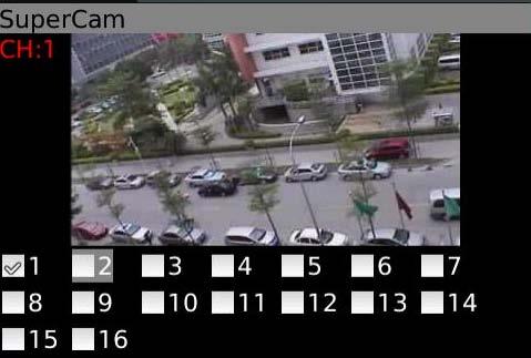
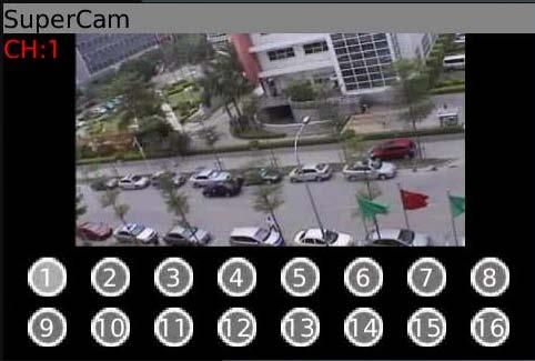
76 Operation Instruction for SuperCam (iphone) 1. Login interface Digital Video Recorder User Manual Enter server s IP address (or domain name), user name and password. Click Remember server to save the setting; click button can quick input saved server address, user name and password. 2. Main Interface Playback playback record file Image image view Log log record Server List device list Live live view Settings software setting Information device information view Help software help center Logoff logoff and return to login interface 3. Live View Interface 70


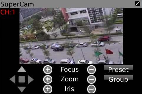
77 Mark 1 Current viewing channel Mark 2 Channel status Switch channels Snap picture Close the video of the current channel Switch to the single image Upward rotates the PTZ Leftward rotates the PTZ Stop rotating the PTZ PTZ, click to switch to Fig 2 interface Record Live audio Switch to four images Downward rotates the PTZ Rightward rotates the PTZ Zoom In/Focus In/Iris Add Zoom Out/Focus Out/Iris Sub Preset elect the preset point Group Set the cruise line Speed Rotate speed of the PTZ H-Reverse Horizontal- Reverse V-Reverse Vertical- Reverse 71


78 4. Image view interface, refer below picture in the left: 5. Record Playback interface, refer below picture in the right: Click the record file to playback. 6. Server list Interface, refer to below picture in the left: 7. Config interface, refer to below picture in the right: 72

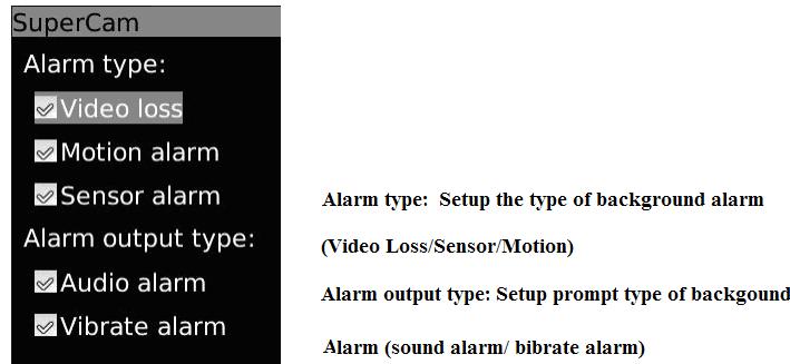
79 Main parameters for mobile phone video configuration Record file clip size: Single video size. When the video size is greater than setup value, change another video files Reserved disk space: Reserved SD Card disk space, when the disk space is less than setup value, the video will be stopped Display configuration: Display mode: User can select one live picture display or four live picture displays Remember display order: User can choose whether to remember display order or not. Alarm configuration:select Audio Alarm. When Video Loss/Sensor/Motion happens,trigger sound alarm. Select shake Alarm. When Video Loss/Sensor/Motion happens,trigger vibrate alarm. 8. Information View Interface 8.4 The installation & operation methods for Android mobile clients Software Installation 73


80 Step 1: run Google Market program Step 2: search SuperCam Step 3: press Install button Step 4: click OK button Step 5: user can view the download and install process in notifications; finished download, the software will install automatically. 74
, user s")


81 Login Enter into server s IP address (or domain name), user s ID and password. Click Remember server to save the setting; click button can quick input saved server address, user name and password. 75


 (Fig 2)")
82 Main menu Playback playback record file Image image view Log log record Server List device list Live live view Settings software setting Information device information view Help software help center Logoff logoff and return to login interface Live view ( Fig 1) (Fig 2) 76

83 Mark 1 Current viewing channel Mark 2 Channel status Switch channels PTZ, click to switch to Fig 2 interface Snap talk Full screen Upward rotates the PTZ Leftward rotates the PTZ Stop rotates the PTZ record Live audio Return Downward rotates the PTZ Rightward rotates the PTZ Zoom In/Focus In/Iris Add Image view Group Zoom Out/Focus Out/Iris Sub Preset Select the preset point Set the cruise line Previous Zoom out Zoom in Next Delete Return to main menu Record playback 77
")


84 (Fig 3) (Fig 4) Click the record file (Fig 3) to playback (Fig 4) Server list Play/pause Full screen stop Return to record file interface (Fig 3) 78


85 Config interface Information view Alarm setting Tick off Sound Alarm, when Video Loss/Sensor/Motion happen,trigger sound alarm; Tick off Vibrate Alarm, when Video Loss/Sensor/Motion happen,trigger vibrate alarm Storage setting User can setup the relevant parameters of mobile video. This function can be valid only insert SD card. Path Save path for mobile video files, the default catalog is /SDCard/. Click button to change path. Reserved disk space reserved SDCard disk space, when the disk space is less than setup value, the video will be stopped Video clip size Single video size. When the video size is greater than setup value, change another video files Remove all recorder delete all current video files files before 79


86 8.5 Installation and operation Methods for BlackBerry Mobile phone Client Installation instruction for BlackBerry Mobile phone Client 1. Open the browser of BlackBerry phone and enter sever address 2. Click SuperCam to link 3. Click Download button on the popup interface and the download progress will be shown. 4. Finished downloading, the software will be installed automatically. 80

 Enter into Menu->Option->Browser Configuration; configure referring to the following figure in the left.")

87 Note: If the software fails to download, please check in accordance with the following steps: 1. Check whether the network of mobile phone is normal or not 2. Check whether DVR server connect network normally or not 3. Modify the option of Browser Configuration. (1) Enter into Menu->Option->Browser Configuration; configure referring to the following figure in the left. (2) Enter into Menu->Option->Cache Operations, clear up browser cache. Refer below picture in the right: Note:When user used the SuperCam software in mobile phone with touch screen, there will be compatible problem. Solution: Enter into Options Menu->Advance options->applications->supercam and click Disable Compatibility button. This problem will be solved. 81
, user s ID and password.")

88 8.5.2 Operation method for Blackberry mobile phone client 1. Login Enter server s IP address (or domain name), user s ID and password. Click Remember server to save the setting; click button can quick input saved server address, user name and password. 2. Main interface Playback playback record file Image image view Log log record Server List device list Information device information Help software help view center Logoff logoff and return to Settings software setting login interface Live live view 82

89 3. Live view 83

90 Note: User can click Return button on the Blackberry phone to return the previous interface. Mark 1 Current viewing channel Mark 2 Channel status Switch channels PTZ, click to switch to Fig 2 interface Snap Background alarm Upward rotates the PTZ Leftward rotates the PTZ Full screen Stop rotating the PTZ Downward rotates the PTZ Rightward rotates the PTZ Zoom In/Focus In/Iris Add Zoom Out/Focus Out/Iris Sub Preset Select the preset point Group Set the cruise line 4. Server list 84
91 5. Software configuration 6. Information view 85
92 Appendix A FAQ Q1. Why the DVR cannot start after connected to the power? a. The adapter has been damaged. Please change an adapter b. The power of the adapter is not enough. Please remove the HDD to check c. Hardware problem Q2. There is not menu output or only has live image display a. Check up whether other devices can display menu or long press ESC key to wait for login dialog box to appear. Q3. The indicator of the DVR lights, but no output. Why? a. The power of the adapter is not enough. Please remove the HDD or change an adapter to try. b. The video format of the DVR is different from that of the monitor. c. Connection problem. Please check the cable and the ports of monitor and DVR. Q4. Why are no images displayed on parts or all of the channels of the DVR? a. Connection problem. Please check the cable and the ports of camera and DVR. b. Camera problem. Please check the cameras. c. The video format of the DVR is different from that of the cameras. Please change DVR system format. Q5. Cannot find HDD a. The power of the adapter is not enough. Please change an adapter to try. b. Connection problem. Please check the power and data cables. c. The HDD is damaged. Change a new one. 86

93 Q6. Cannot record a. Don't format HDD. Please format it manually first. b. Don't enable record function or incorrect setup. Please refer to Chapter 5 Record search & playback and backup. c. HDD is full and not enables recycle function. Please refer to Record Configuration. Chang a new HDD or enable recycle. d. The HDD is damaged. Change a new one. Q7. Cannot use mouse. a. wait 1-2 minutes after mouse connected. b. Not detected. Plug/unplug several times. c. The mouse is incompatible. Please change a mouse. Q8. Cannot download ActiveX control. a. IE browser blocks ActiveX. Please do setup following below. 1 Open IE browser. Click Tools-----Internet Options. 2 select Security------Custom Level.Refer to Fig 8-1: 3 Enable all the sub options under ActiveX controls and plug-ins refer to Fig 8-2: 87


94 4 Then click ok to finish setup. Digital Video Recorder User Manual b. Other plug-ins or anti-virus block ActiveX. Please uninstall or close them. Fig8-1 Fig8-2 Q9: How to deal with when DVR starts, it displays please wait all the time First possible reason: hard-disk cable and data cable are not well connected. Solution: Please check the connection of hard-disk cable and data cable and make sure they are well connected; If still not working, please unplug them and then try re-plugging again; Second possible reason: It is forced to stop because hard disk has disabled track which causes the system checking hard disk cannot skip 88
95 Solution: Change another new hard disk or reformat the broken one Digital Video Recorder User Manual Q10: How to input password and digital numbers The method to input password and digital numbers is to click the box behind password or items needing to input by numbers, and then the small keyboard will appear. Please select number or letter to input (the initial password is ), or you can use the digital keys in the front panel, or the digital keys on the remote controller. Q11: What are the minimum configurations of PC for clients connecting? PC Module Parameters CPU Intel Celeron 2.4G Motherboard Intel 845 HDD 80G RAM 512M VGA NVIDIA GeForce MX440/FX5200; ATIRADEON 7500/X300 OS Windows 2000(SP4 above) /Windows XP(SP2 above) /VISTA DirectX 9.0 Q12: What are the PC configurations for 16-ch real time product with fully open channel mainstream? PC Module Parameters CPU Intel Core(TM)2 Duo CPU E4600 Motherboard G31/P31 chip HDD 80G RAM 1GB VGA GMA3100/NVIDIA GeForce 8400/ATI RADEON HD

; click Turn User Account on or off.")
96 OS Windows 2000(SP4 above) /Windows XP(SP2 above) VISTA DirectX 9.0 Q13: How to handle the situation when codec Control is blocked to install in the VISTA or Win7 system? If user gets this problem, may have two ways to fix it: a. Enter Control Panel User Account and Family Safety User Account Control(refer to below picture); click Turn User Account on or off. Cancel Use User Account Control (UAC) to help protect your computer. b. Right click IE browser (refer to Fig 13-2), select Run as administrator to run browser. 90
DVR User Manual. For H.264 4/8/16-channel digital video recorder All rights reserved
 DVR User Manual For H.264 4/8/16-channel digital video recorder All rights reserved CAUTION Please read this user manual carefully to ensure that you can use the device correctly and safely We do not warrant
DVR User Manual. For H.264 4/8-channel digital video recorder All rights reserved
 DVR User Manual For H.264 4/8-channel digital video recorder All rights reserved CAUTION Please read this user manual carefully to ensure that you can use the device correctly and safely We do not warrant
DVR User Manual. For H.264 4/8/16-channel digital video recorder All rights reserved
 DVR User Manual For H.264 4/8/16-channel digital video recorder All rights reserved CAUTION Please read this user manual carefully to ensure that you can use the device correctly and safely We do not warrant
DVR User Manual PS-9304S PS-9308S
 DVR User Manual PS-9304S PS-9308S For H.264 4/8/16-channel digital video recorder All rights reserved CAUTION Please read this user manual carefully to ensure that you can use the device correctly and
DVR User Manual. For H.264 4/8/16-channel digital video recorder All rights reserved
 DVR User Manual For H.264 4/8/16-channel digital video recorder All rights reserved CAUTION Please read this user manual carefully to ensure that you can use the device correctly and safely We do not warrant
DVR User Manual. For H.264 4/8-channel digital video recorder All rights reserved
 DVR User Manual For H.264 4/8-channel digital video recorder All rights reserved CAUTION Please read this user manual carefully to ensure that you can use the device correctly and safely We do not warrant
DVR User Manual. For H.264 4/8/16-channel digital video recorder All rights reserved
 DVR User Manual For H.264 4/8/16-channel digital video recorder All rights reserved CAUTION Please read this user manual carefully to ensure that you can use the device correctly and safely We do not warrant
DVR User Manual. For H.264 4/8/16 digital video recorder All rights reserved
 DVR User Manual For H.264 4/8/16 digital video recorder All rights reserved CAUTION Please read this user manual carefully to ensure that you can use the device correctly and safely We do not warrant all
DVR User Manual. For H.264 4/8/16-channel digital video recorder All rights reserved
 DVR User Manual For H.264 4/8/16-channel digital video recorder All rights reserved CAUTION Please read this user manual carefully to ensure that you can use the device correctly and safely We do not warrant
DVR User Manual. For H.264 4/8/16-channel digital video recorder
 For H.264 4/8/16-channel digital video recorder This manual explains all the functions of your DVR. The manual will take you step-by-step of how to view your cameras, playback video, and how to backup
Thank you for purchasing our product. Please read this User s Manual before using the product. Change without Notice. 4 / 8 CH DVR User s Manual
 Thank you for purchasing our product. Please read this User s Manual before using the product. Change without Notice 4 / 8 CH DVR User s Manual CAUTION Please read this user manual carefully to ensure
DVR User Manual. For H.264 4/8/16-channel digital video recorder All rights reserved
 DVR User Manual For H.264 4/8/16-channel digital video recorder All rights reserved CAUTION Please read this user manual carefully to ensure that you can use the device correctly and safely We do not warrant
H.264 Dual Stream Network DVR 8 Channel & Digital Video Recorder USER MANUAL. Model #: QT528
 H.264 Dual Stream Network DVR 8 Channel CIF@240fps & D1@240fps Digital Video Recorder USER MANUAL Model #: QT528 www.q-see.com Rev 12/6/2010 CAUTION Please read this user manual carefully to ensure that
16-ch Standalone DVR User Manual
 16-ch Standalone DVR User Manual For H.264 16 Channel Digital Video Recorder All rights reserved *All contents of this document may change without prior notice. CAUTION Please read this user manual carefully
Quick Start Guide 4/8/16-Ch DVR
 Quick Start Guide 4/8/16-Ch DVR 1 1. Install Hard Drive &DVD Writer 1.1Install Hard Drive Notice: 1. Support two SATA hard drives. Please use the hard drive the manufacturers recommend specially for security
Quick Start Guide 4/8-CH DVR
 Quick Start Guide 4/8-CH DVR 1 1. Install Hard Drive &DVD Writer 1.1 Install Hard Drive Notice: 1. this series support one SATA hard drives. Please use the hard drive the manufacturers recommend specially
DVR User Manual. For H.264 4/8/16-channel digital video recorder All rights reserved
 For H.264 4/8/16-channel digital video recorder All rights reserved CAUTION Please read this user manual carefully to ensure that you can use the device correctly and safely We do not warrant all the content
Quick Start Guide 4/8/16-Ch DVR
 Quick Start Guide 4/8/16-Ch DVR 1 1. Install Hard Drive &DVD Writer 1.1Install Hard Drive Notice: 1.This series support one SATA hard drive. Please use the hard drive the manufacturers recommend specially
Quick Start Guide 4/8/16-CH DVR.
 Quick Start Guide 4/8/16-CH DVR 1. Install Hard Drive &DVD Writer 1.1 Install Hard Drive Notice: 1. Support two SATA hard drives. Please use the hard drive the manufacturers recommend specially for security
Quick Start Guide 4/8/16/24-Ch DVR
 Quick Start Guide 4/8/16/24-Ch DVR 1.1 Install Hard Drive 4/8/16/24-CH DVR Quick Start Guide Notice: 1.4/3/16-ch DVR supports one SATA hard drive. 24-ch DVR supports three SATA hard drives. Please use
Digital Video Recorder User Manual. DVR User Manual. For H channel/ 8-channel/16-channel Digital Video Recorder All rights reserved
 DVR User Manual For H.264-4-channel/ 8-channel/16-channel Digital Video Recorder All rights reserved i CAUTION ii Please read this user manual carefully to ensure that you can use the device correctly
DVR User s Manual. For H FPS /8-channel digital video recorder All rights reserved. Rev
 QSDT8DP DVR User s Manual For H.264-240 FPS /8-channel digital video recorder All rights reserved Rev 120209 i QSDT8DP User s Manual CAUTION Please read this user manual carefully to ensure that you can
Digital Video Recorder User Manual. DVR User Manual. For H channe/ 8-channel/16-channel Digital Video Recorder All rights reserved
 DVR User Manual For H.264-4-channe/ 8-channel/16-channel Digital Video Recorder All rights reserved i CAUTION Please read this user manual carefully to ensure that you can use the device correctly and
DVR User Manual. For H.264 4/8/16-channel digital video recorder All rights reserved
 For H.264 4/8/16-channel digital video recorder All rights reserved CAUTION Please read this user manual carefully to ensure that you can use the device correctly and safely. We do not warrant all the
H.264 4/8/16 CH Analogue HD TVI-DVR User s Manual
 Thank you for purchasing our product. Please read this user s manual before using the product. Change without notice H.264 4/8/16 CH Analogue HD TVI-DVR User s Manual Type A: 1 SATA (TVI-04 / TVI-08 /
DVR User Manual. For H.264-4/8/16-channel digital video recorder All rights reserved
 DVR User Manual For H.264-4/8/16-channel digital video recorder All rights reserved CAUTION Please read this user manual carefully to ensure that you can use the device correctly and safely We do not warrant
QSD2308L/QSD2316L DVR User s Manual
 QSD2308L/QSD2316L DVR User s Manual NOTE: We use two different front panel designs on these models. They have the same function buttons but they are arranged differently. Please match the front panel on
DVR User Manual. For H.264 8/16-channel digital video recorder All rights reserved
 For H.264 8/16-channel digital video recorder All rights reserved CAUTION Please read this user manual carefully to ensure that you can use the device correctly and safely We do not warrant all the content
DVR User Manual. For H.264 8/16-channel digital video recorder All rights reserved
 For H.264 8/16-channel digital video recorder All rights reserved CAUTION Please read this user manual carefully to ensure that you can use the device correctly and safely. We do not warrant all the content
DVR User Manual MODEL: QT108WD QT 116WD. For H.264 8/16-channel digital video recorder All rights reserved
 MODEL: QT108WD QT 116WD For H.264 8/16-channel digital video recorder All rights reserved CAUTION Please read this user manual carefully to ensure that you can use the device correctly and safely. There
DVR User Manual. For H.264 4/8/16-channel digital video recorder All rights reserved
 For H.264 4/8/16-channel digital video recorder All rights reserved CAUTION Please read this user manual carefully to ensure that you can use the device correctly and safely. We do not warrant all the
DVR User Manual. For H.264 4/8/16-channel digital video recorder All rights reserved
 For H.264 4/8/16-channel digital video recorder All rights reserved CAUTION Please read this user manual carefully to ensure that you can use the device correctly and safely. There may be several technically
DVR User Manual. For H channel digital video recorder All rights reserved
 For H.264 4-channel digital video recorder All rights reserved CAUTION Please read this user manual carefully to ensure that you can use the device correctly and safely. We do not warrant all the content
DVR User Manual. For H.264 4/8/16-channel digital video recorder All rights reserved
 DVR User Manual For H.264 4/8/16-channel digital video recorder All rights reserved CAUTION Please read this user manual carefully to ensure that you can use the device correctly and safely. There may
DVR User Manual. For H channel digital video recorder All rights reserved
 For H.264 16-channel digital video recorder All rights reserved CAUTION Please read this user manual carefully to ensure that you can use the device correctly and safely. There may be several technically
DVR User Manual. For H.264 4/8/16-channel digital video recorder All rights reserved
 For H.264 4/8/16-channel digital video recorder All rights reserved CAUTION Please read this user manual carefully to ensure that you can use the device correctly and safely We do not warrant all the content
NVR User Manual. For H.264 4/8/16-channel network video recorder All rights reserved
 For H.264 4/8/16-channel network video recorder All rights reserved CAUTION Please read this user manual carefully to ensure that you can use the device correctly and safely. There may be several technically
NVR User Manual. For H.264 4/8/16-channel network video recorder All rights reserved
 For H.264 4/8/16-channel network video recorder All rights reserved CAUTION Please read this user manual carefully to ensure that you can use the device correctly and safely. There may be several technically
NVR User Manual. For H channel network video recorder All rights reserved
 For H.264 4-channel network video recorder All rights reserved CAUTION Please read this user manual carefully to ensure that you can use the device correctly and safely. There may be several technically
NVR User Manual. For H channel network video recorder All rights reserved
 For H.264 4-channel network video recorder All rights reserved CAUTION Please read this user manual carefully to ensure that you can use the device correctly and safely. We do not warrant all the content
DVR User Manual. For H.264 4/8/16/24/32-channel digital video recorder All rights reserved
 For H.264 4/8/16/24/32-channel digital video recorder All rights reserved CAUTION Please read this user manual carefully to ensure that you can use the device correctly and safely. We do not warrant all
QSTD2404/QSTD2408/QSTD2416 Digital Video Recorders User s Manual
 QSTD2400 Series DVR User s Manual QSTD2404/QSTD2408/QSTD2416 Digital Video Recorders User s Manual For H.264-4-channel/ 8-channel/16-channel Digital Video Recorders All rights reserved Rev 091708 i QSTD2400
User Manual. 4 Channel 960H High Performance Standalone DVR with HDMI 1080p Output. Model: D4960H-H-BK
 Model: D4960H-H-BK 4 Channel 960H High Performance Standalone DVR with HDMI 1080p Output User Manual 8805 Jones. Rd Ste C104, Houston Texas 77065 * 1-888-861-7351 * www.zuummedia.com Statement: This manual
NVR User Manual. For H channel network video recorder All rights reserved
 For H.264 16-channel network video recorder All rights reserved CAUTION Please read this user manual carefully to ensure that you can use the device correctly and safely. We do not warrant all the content
H.264 4/ 8/ 16 CH 960H DVR User s Manual
 Thank you for purchasing our product. Please read this user s manual before using the product. Change without notice H.264 4/ 8/ 16 CH 960H DVR User s Manual CAUTION Please read this user manual carefully
TBK VISION PLUS TBK-NVR5008 / TBK-NVR5016 User manual v1.0
 Network Video Recorder TBK VISION PLUS TBK-NVR5008 / TBK-NVR5016 User manual v1.0 Please read this manual carefully for correct use of the product and preserve it for reference purposes Notes Please read
DVR User Manual. For H /32-channel digital video recorder All rights reserved
 DVR User Manual For H.64 16/-channel digital video recorder All rights reserved CAUTION Please read this user manual carefully to ensure that you can use the device correctly and safely. There may be several
CCTV42 System2 DVR Quick Start Guide 4/8/16-Ch DVR
 CCTV42 System2 DVR Quick Start Guide 4/8/16-Ch DVR If you have purchased a DVR / Hard drive package from us then we will have already installed the hard drive(s) and configured the basic settings on your
errors, or places that do not match the product. If you have any unsolved please contact our technical support department.
 - 0 - Statement: This manual may contain several technical inaccuracies or typographical errors, or places that do not match the product. If you have any unsolved problems in the process of using product
AHD Series DVR User Manual (Version and Higher)
") AHD Series DVR User Manual (Version 3.4.3 and Higher) PROVISION-ISR AHD DVR User Manual For H.64 AHD digital video recorder All rights reserved CAUTION Please read this user manual carefully to ensure
AHD Series DVR User Manual (Version 3.4.3 and Higher) PROVISION-ISR AHD DVR User Manual For H.64 AHD digital video recorder All rights reserved CAUTION Please read this user manual carefully to ensure
NVR User Manual. For H /24-channel network video recorder All rights reserved
 For H.264 16/24-channel network video recorder All rights reserved CAUTION Please read this user manual carefully to ensure that you can use the device correctly and safely. There may be several technically
Digital Video Recorder
 Digital Video Recorder CAUTION Please read this user manual carefully to ensure that you can use the device correctly and safely. We do not warrant all the content is correct. The contents of this manual
16CH Hybrid DVR_ User Manual (AHD+TVI+IP+960H)
") Thank you for purchasing our product. Please read this user s manual before using the product. Change without notice 16CH Hybrid DVR_ User Manual (AHD+TVI+IP+960H) CAUTION Please read this user manual
Thank you for purchasing our product. Please read this user s manual before using the product. Change without notice 16CH Hybrid DVR_ User Manual (AHD+TVI+IP+960H) CAUTION Please read this user manual
DVR User Manual. For H /32-channel digital video recorder All rights reserved
 DVR User Manual For H.264 16/32-channel digital video recorder All rights reserved CAUTION Please read this user manual carefully to ensure that you can use the device correctly and safely. There may be
PROVISION-ISR NVR-8200(1U) User Manual
 User Manual") PROVISION-ISR NVR-8200(1U) User Manual 8CH 720P Real-Time Conventional NVR For H.264 8-channel network video recorder All rights reserved CAUTION Read this user manual carefully and use the device correctly
PROVISION-ISR NVR-8200(1U) User Manual 8CH 720P Real-Time Conventional NVR For H.264 8-channel network video recorder All rights reserved CAUTION Read this user manual carefully and use the device correctly
Digital Video Recorder User Manual
 Statement Thank you for purchasing our product. If there is any question or request, please do not hesitate to contact dealer. This manual may contain several technical inaccuracies or typographical errors,
DVR User Manual. For H.264 4/8/16-channel digital video recorder All rights reserved. Your local installer:
 For H.264 4/8/16-channel digital video recorder All rights reserved Your local installer: www.eaglesecuritysolutions.co.uk CAUTION Please read this user manual carefully to ensure that you can use the
DHE-04 DHE-08 DHE H H.264 DVR 4 / 8 / 16 CH. Quick Setup Guide PACKAGE CONTENTS A. B. C. D. E. F. G. H. Inside the DVR I.
 960H H.264 DVR 4 / 8 / 16 CH. Quick Setup Guide DHE-04 DHE-08 DHE-16 PACKAGE CONTENTS A. One (1) DHE-04 / DHE-08 / DHE-16 DVR B. One (1) Remote Controller C. Two (2) AAA Battery for Remote Controller D.
DDR-08 DDR-16 Full D1 Realtime H.264 DVR 8 / 16 CH. Quick Setup Guide
 DDR-08 DDR-16 Full D1 Realtime H.264 DVR 8 / 16 CH. Quick Setup Guide PACKAGE CONTENTS A. One (1) DDR-08 / DDR-16 DVR B. One (1) Remote Controller C. Two (2) AAA Battery for Remote Controller D. One (1)
Yongh. Please read this manual carefully for correct use of the product and preserve it for reference purposes
 User Manual Yongh Please read this manual carefully for correct use of the product and preserve it for reference purposes Notes Please read this user manual carefully to ensure that you can use the device
NVR&IPCAM USER MANUAL V1.0 (USER MANUAL) V1.0. Thanks for choosing our products, please read this manual carefully before use!
 V1.0. Thanks for choosing our products, please read this manual carefully before use!") NVR&IPCAM (USER MANUAL) V1.0 Thanks for choosing our products, please read this manual carefully before use! NOTICE Installation condition 1) In order to ensure your rights, please read this manual carefully
NVR&IPCAM (USER MANUAL) V1.0 Thanks for choosing our products, please read this manual carefully before use! NOTICE Installation condition 1) In order to ensure your rights, please read this manual carefully
Network Video Recorder User Manual. alarm shop
 Statement Thank you for purchasing our product. If there is any question or request, please do not hesitate to contact dealer. This manual may contain several technical inaccuracies or typographical errors,
Yongh. Please read this manual carefully for correct use of the product and preserve it for reference purposes
 User Manual Yongh Please read this manual carefully for correct use of the product and preserve it for reference purposes Notes Please read this user manual carefully to ensure that you can use the device
TBK VISION PLUS TBK-NVR5016P8 User manual v1.0
 Network Video Recorder TBK VISION PLUS TBK-NVR5016P8 User manual v1.0 Please read this manual carefully for correct use of the product and preserve it for reference purposes Notes Please read this user
User Manual HD TVI Hybrid DVR
 User Manual HD TVI Hybrid DVR Notes! Please read this user manual carefully to ensure you can use the DVR correctly and safely.! This DVR should only be operated with the power adaptor supplied. This is
QSD2304L DVR User s Manual CONTENTS
 CONTENTS CHAPTER 1 Introduction........ 1 1.1 DVR Introduction....... 1 1.2 Main Features and Specifications..... 1 CHAPTER 2 Panel Layouts... 3 2.1 Check the Accessories.... 3 2.2 Front Panel Layout.........
Hybrid HD 1080p User Manual
 Hybrid HD 1080p User Manual Notes! Please read this user manual carefully to ensure that you can use the device correctly and safely.! This device should be used only with the power supply provided.! Do
Analog High Definition DVR. Stand alone digital video recorder. User Manual H.264 AHD DVR
 Analog High Definition DVR Stand alone digital video recorder User Manual H.264 AHD DVR WARNING To reduce the risk of fire or electric shock, do not expose this appliance to rain or moisture. All the safety
HLong Asia Industrial
 SDI DVR Stand alone digital video recorder HLong Asia Industrial Thank you for using the company's products! This manual describes only the host functions basic operation. Product design and specification
NVMS1000. User Manual
 NVMS1000 User Manual Contents 1 Software Introduction... 1 1.1 Summary... 1 1.2 Operation Environment... 1 1.3 Install and Uninstall... 2 1.3.1 Install the Software... 2 1.3.2 Uninstall the Software...
VMS-A1 Client Software. User Manual
 VMS-A1 Client Software User Manual Contents Contents... 2 Chapter1. Overview... 4 1.1 Description... 4 1.2 Features & Functions... 4 Chapter2. Update Info... 6 Chapter3. Starting VMS-A1... 7 3.1 Installing
R4, R8, R16 Digital Video Recorders Quick Setup Guide
 R4, R8, R16 Digital Video Recorders Quick Setup Guide This guide provides instructions to initially setup the R16 (16 channel) digital video recorders (DVR). The DVR supports these advanced features: 2
USER MANUAL. Mac Version
 USER MANUAL Mac Version Contents 1 Software Introduction... 1 1.1 Summary... 1 1.2 Install and Uninstall... 1 1.2.1 Install the Software... 1 2 Login Software... 3 2.1 Login... 3 2.2 Control Panel Instruction...
User Manual MODEL QT528 QT526. QT5 Series Network DVR With Real-Time D1 Recording
 User Manual MODEL QT528 QT526 QT5 Series Network DVR With Real-Time D1 Recording 1 About this Manual Thank You for Choosing a Q-See Product! All of our products are backed by a conditional service warranty
4CH/ 8CH/ 16CH Digital Video Recorder
 4CH/ 8CH/ 16CH Digital Video Recorder DVR204B/ 208B/ 216B INSTRUCTION MANUAL DIRECTORY CHAPTER 1 Hard Disk Installing (Standard shipping products include neither HDD or R/W)...2 CHAPTER 2 Panel Appearance...4
NVMS User Manual
 NVMS-1000 User Manual Contents 1 Software Introduction...1 1.1 Summary... 1 1.2 Operation Environment... 1 1.3 Install and Uninstall... 2 1.3.1 Install the Software... 2 1.3.2 Uninstall the Software...
Pro71600N3 NVR User Manual
 Pro71600N3 NVR User Manual User Information Admin User Name: Admin Password: IP Address: System Name: Table Of Contents 1. Menu Operation...4 1.1 Main Menu...4 2. Start & Shutdown System...5 2.1 Start
NVMS User Manual. Version 2.1.0
 NVMS-1000 User Manual Version 2.1.0 Contents 1 Software Introduction... 1 1.1 Summary... 1 1.2 Operation Environment... 1 1.3 Install and Uninstall... 2 1.3.1 Install the Software... 2 1.3.2 Uninstall
SuperDVR Software User Manual
 SuperDVR Software CONTENTS 1 Introduction... 5 1.1 Summarization... 5 1.2 Install Video Capture Card Driver... 7 2 Main Display Interface... 10 2.1 Display Control Panel... 11 2.1.1 Display Control Panel...
NUBIX H.264 DVR Setup Guide
 Package Content NUBIX H.264 DVR Setup Guide Inspect the packaging carton. Make sure the NUBIX H.264 DVR is properly delivered. Remove all items from the box and make sure the box contains the following
JVS-D7216 Standalone DVR User Manual
 Menu JVS-D7216 Standalone DVR User Manual JVS-D7216 Standalone DVR Instructions 1. Introduction..4 1.1 Product Description...4 1.2 Features..4 1.3 Specifications...4 2. Product Features....6 2.1 Panel
SAMSUNG ALL-IN-ONE SECURITY SYSTEM
 Quick Start Guide KIT MODEL SDH-B74041/SDH-B74081 DVR MODEL SDR-B74301 SAMSUNG ALL-IN-ONE SECURITY SYSTEM Thank you for purchasing the Samsung DVR Security System. Follow the simple steps in this guide
truvision DVR 31 Quick Start Guide
 truvision DVR 31 Quick Start Guide Content Contact information 1 Package contents 1 Installation environment 1 Setting up the DVR 31 1 Connecting the devices 2 Turning on the DVR 31 2 Operating the DVR
TruVision DVR 30 Quick Start Guide
 TruVision DVR 30 Quick Start Guide Content Contact information 1 Package contents 1 Installation environment 1 Setting up the TVR 30 1 Connecting the devices 2 Turning on the TVR 30 2 Operating the TVR
Pro7804N1 NVR User Manual
 Pro7804N1 NVR User Manual Pro7804N1 User Manual BW R6.indd 1 User Information Admin User Name: Admin Password: IP Address: System Name: Table Of Contents 1. Menu Operation...4 1.1 Main Menu...4 2. Start
Yongh. Please read this manual carefully for correct use of the product and preserve it for reference purposes
 User Manual Yongh Please read this manual carefully for correct use of the product and preserve it for reference purposes Notes Please read this user manual carefully to ensure that you can use the device
NVMS User Manual
 NVMS-1000 User Manual Contents 1 Software Introduction...1 1.1 Summary... 1 1.2 Operation Environment... 1 1.3 Install and Uninstall... 2 1.3.1 Install the Software... 2 1.3.2 Uninstall the Software...
ALL-IN-ONE SECURITY SYSTEM
 DO NOT OPEN CAUTION : TO REDUCE THE RISK OF ELECTRICAL SHOCK DO NOT OPEN COVERS. NO USER SERVICEABLE PARTS INSIDE. REFER SERVICING TO QUALIFIED SERVICE PERSONNEL. WARNING : TO PREVENT FIRE OR SHOCK HAZARD.
NVMS1000. User Manual
 NVMS1000 User Manual Contents 1 Software Introduction... 1 1.1 Summary... 1 1.2 Operation Environment... 1 1.3 Install and Uninstall... 2 1.3.1 Install the Software... 2 1.3.2 Uninstall the Software...
User Manual MODEL QT504 QT518 QT5116 QT528 QT526 QT536. QT5 Series Network DVR With Real-Time D1 Recording
 User Manual MODEL QT504 QT518 QT5116 QT528 QT526 QT536 QT5 Series Network DVR With Real-Time D1 Recording 1 About this Manual Thank You for Choosing a Q-See Product! All of our products are backed by a
NVR User Manual. NVR User Manual For further help, please visit
 NVR User Manual NVR User Manual For further help, please visit www.zmodo.com Introduction This product series is a 4 channel embedded NVR with pentaplex functionality: the product will perform video audio
Chapter 1 Features FEATURES
 Chapter 1 Features Operation Playback, recording and network transmission simultaneously Real time full screen or quad screen display 2X digital zoom and Picture-in-picture display Easy operations by shuttle
4CH H.264 Multiplex DVR
 4CH H.264 Multiplex DVR User Manual VER.:1.0, P/N: R040199A This symbol is intended to alert the user to the presence of unprotected Dangerous voltage" within the product's enclosure that may be strong
4CH Real Time DVR. User Guide INFORMATION MAY CHANGE WITHOUT NOTICE. Digital Video Recorder
 User Guide INFORMATION MAY CHANGE WITHOUT NOTICE. Table of Contents Caution... 4 Package Contents... 4 Introduction... 5 1. Product Overview...5 2. Front Panel...5 3. Rear Panel...6 4. IR Remote Controller
Pro7400H1 Hybrid DVR User Manual
 Pro7400H1 Hybrid DVR User Manual User Information Admin User Name: Admin Password: IP Address: System Name: Table Of Contents 1. Menu Operation... 4 1.1 Main Menu... 4 2. Start Up/Shutdown System... 5
DVR RANGE ENGINEER MANUAL
 INSPIRE DVR RANGE ENGINEER MANUAL Contents Hardware Inspire DVR range Connections Connecting a mouse Connecting keyboard Connecting PTZ cameras Connecting Keyboard/PTZ Alarm connections Using front panel
Lite H.264 DVR Setup Guide
 Package Content Lite H.264 DVR Setup Guide Inspect the packaging carton. Make sure the Lite H.264 DVR is properly delivered. Remove all items from the box and make sure the box contains the following items.
C n o t n e t n e t n s
 Preface Thank you for choosing our product, for a better understanding of the product, we recommend you read the instruction and safety information before use. Notice: This user manual is an operation
Chapter 3 Operating instructions
 Chapter 3 Operating instructions Summary This chapter describes the how to control and navigate through the TVR 30 s menus and options. Content Control interfaces 10 Controlling the TVR 30 10 Front panel
SPY-DVR4HYB & SPY-DVR8HYB SPY-DVR4HYB2ND & SPY-DVR8HYB2ND
 SPY-DVR4HYB & SPY-DVR8HYB SPY-DVR4HYB2ND & SPY-DVR8HYB2ND Instructions 1.0 INTRODUCTION 1.1 Main menu 2.0 SPLIT SCREEN 3.0 SYSTEM SETUP 3.1 General Setup 3.2 Time Setup 3.3 HDD Setup 3.4 Screen Setup 3.5