User Manual. Before trying to connect or operate this product, please read this manual completely.
|
|
|
- Adrian Harvey
- 5 years ago
- Views:
Transcription

1 User Manual Before trying to connect or operate this product, please read this manual completely.
2
3 Table of Contents 1 PRODUCT FEATURES... 4 PRODUCT INSTRUCTIONS... 4 PRODUCT FEATURES DESCRIPTION OF THE SURFACE... 5 THE HARDWARE VIEW... 5 THE RESET BUTTON... 7 THE ALARM WIRING DIAGRAMS INSTALLATION... 8 HARDWARE INSTALLATION... 8 WPS - PUSH BUTTON SETUP... 8 SOFTWARE INSTALLATION... 9 Where to download... 9 Configuration Android Operating System Configuration ios Operating System UPDATING SYSTEM SOFTWARE Network Configuration CABLE CONNECTIONS CONFIGURE YOUR IP CAMERA NETWORK SETTINGS Set IP Address TCP/IP COMMUNICATION SOFTWARE TCP/IP INSTALLATION TCP/IP CONFIGURATION SETTING CONNECTION TESTING Configuration Using A Web Browser
4 WEB CONFIGURATION PAGES Connecting the IP camera Live Video Setup FREQUENTLY ASKED QUESTIONS SPECIFICATIONS Appendix: The Playback Utility Tool-- CMS INTRODUCTION TO THE CMS INSTALL THE CMS IN YOUR PC START TO USE THE CMS OPERATION Live View Playback Settings
5 SAFETY PRECAUTIONS All the following safety and operational instructions to prevent harm or injury to the operator(s) or other persons should be read carefully before the unit is activated. WARNING To prevent fire or shock hazard, avoid exposing this unit to rain or moisture. Do not block ventilation openings. Do not place anything on top of the unit that might spill or fall into it. Do not attempt to service this unit yourself, as opening or removing covers may expose you to dangerous voltage or other hazards. Please refer all servicing to your distributor/ retailer. Do not use liquid cleaners or aerosols for cleaning. To prevent fire or electric shock, do not overload wall outlets or extension cords. Please only select a power adapter or power certified by UL and marked at 24Vac / 60 Hz, minimum 1A, class 2 or LPS. CAUTION Risk of explosion if battery is replaced by an incorrect type. Dispose of used batteries according to the instructions. 3
6 1 PRODUCT FEATURES Product Instructions Here's a new series from APPRO -- cameras that act as basic watchguards in your premises -- lightweight, simple formatted, inexpensive, and no fuss to install. These watchkeepers are the ideal stuff for the safety of your home and office interiors. Our cube camera brings you dependable video surveillance in a focused & targetted environment. This is an easily installable, smart surveillance camera, ideal for low - light settings like your mini office or living spaces. It combines a high performance Megapixel sensor with a built - in IR LED that maintains close watch and clear vision in totally dark conditions. The camera has a built - in mechanical IR - cut filter for day and night applications equally. Its wireless capability means you can site your camera in any place within range of your wireless network. The camera sets you up with a swift and dependable wireless connection which will help you see live video feeds from your camera in any place at any time. The Site Survey feature helps you easily see or link up to a wireless network close at hand. The camera's standard Ethernet port gives you connections to regular wired networks. The camera's flexible connectivity by way of its input and output ports link you to network devices like IR sensors, switches and alarm relays. Smooth to configure and operate, our camera comes with the Universal Plug-n-Play feature which gets computers running on Windows XP / Vista / 7 to automatically recognize the camera and add it to the network. Product Features Simultaneous H.264 and MJPEG video compressions. Multi-profile applications: Selectable resolutions, frame rates, video qualities, and compression. Advanced motion detection (512 zones, sensitivity: 0~100 %). Supports ONVIF. Supports Wi-Fi. 4
7 2 DESCRIPTION OF THE SURFACE The Hardware View The Front View Camera Lens: Records video of the surrounding area. 2. Status LED: Indicates the camera's current status. 3. WPS Status LED: Indicates the WPS connection status of the camera. While connecting, the blue LED will flash. 4. Microphone: Records audio from the surrounding area. 5. Infrared LED: Used to illuminate the camera's field of view at night. 6. PIR Sensor: Passive Infrared sensor for motion detection. 7. ICR Sensor: The IR-Cut Removable sensor monitors lighting conditions and switches between color and infrared accordingly. 5
8 The Rear View: 2 DC-5V ETHERNET RESET WPS Ethernet Port: This is a standard RJ-45 connector for 10/100 Mbps Ethernet networks. 2. Power Connector: A DC 5V inlet that connects to an external power supply. 3. DI/DO Connector: I/O connectors for connecting with external devices. 4. Reset Button: Press and hold this button for 10 seconds to back to its factory default settings. 5. WPS Button: Press this button, then push and hold another WPS button on your router for 5 seconds to set up a wireless connection automatically. 6. Micro SD Card Slot: Insert a Micro SD card for local storage including recorded image and video. 7. Speaker: Provides the camera s audio signal output. 8. Adjustment Ring: Tighten or loosen the adjustment ring to adjust the camera's position. 6
9 The Reset Button You can use the Reset button to reset the camera operations back to default. Press the Reset button for about 10 seconds. Blue screens of the analog output are displayed, and a text saying RESETTING appears. The Alarm wiring diagrams This is a 4-PIN connector including the Digital output/input, DC output and GROUND items for connecting with external devices. DO DI 5V GND DC Power 5V + GND N.C/N.O DI DC Power 3V~12V + 5V Reed switch R 100 ma DO Diode ALARM 7
10 3 INSTALLATION Please follow the instructions and the diagram below to set up the system. Hardware Installation 1. Connect Ethernet cable to the rear panel of the camera. 2. Plug in the power connection to the camera. 3. Confirm the correct network connection status. DC-5V ETHERNET WPS - Push Button Setup To create a WPS connection: 1. Press and hold the WPS button for about 5~6 seconds. The WPS status LED will flash. 2. Press the WPS button on your router within 60 seconds. The camera will automatically create a wireless connection to your router. While connecting, the status LED will flash. After the connection process is complete, the status LED will turn solid. RESET WPS Note Please make sure that your router supports WPS, then you can use the WPS button on the camera to easily create a secure wireless connection to your network. On some routers, you may need to log in to the web interface and click on an on-screen button to activate the WPS feature. 8
11 Software Installation Before installing the apps to your mobile phone for remote surveillance, make sure that you have checked the following: 1. Your mobile platform is ios or Android. 2. You might be charged for Internet access via wireless or 3G/4G networks. For the Internet access rate details, please check with your local network operator or service provider. 3. Your IP camera is powered on and connected to Internet/ Intranet. Where to download App for Android QR-code App for ios QR-code 9


12 Configuration Android Operating System Browse to where AppPro is installed by default on your mobile phone when the installation is completed. Find AppPro and activate it. Add Camera Camera List Two methods to add a new camera. 1. Scan QR code of the camera: You can just scan the QR code to add a camera. Select + (Add) on the screen to add the new camera. 2. Manually type in the camera ID and password: Enter the information needed to access your device, such as the DeviceID and Password (default:9999). Select + (Add) on the screen to add the new camera. Start to monitor. 1. Choose the camera you want to access on the camera list. Your mobile phone will start connecting to your camera. 2. Select the to enter the camera configuration setting page. 10


13 Configuration- Setting Configuration- Change Password Change the settings of resolution, video mode, You can change the Password here. Click Yes to video area, FPS, audio mode and enable/disable activate it. Please use the new password to Reverse Image function. Then click. connect the camera by using this app next time. Configuration- Notification Setup Configuration- Local Storage Please set the SD card Remote Record Type, Alert Type, Sensibility, and the Push Notification functions first. Then click. You can view the saved video clips and images in your mobile device here. 11
 Remote Storage-")


14 Configuration- Remote Storage (SD card) Remote Storage- Normal/ Alert Record List You can view/ download the saved video clips and images in the SD card here. Note: Please insert an SD Card to the camera first. Remote Storage- Downloaded Files This allows you to search a recorded video stored in the SD card of the camera. Click the date and press the hour button to proceed. Delete Camera You can manage the exported SD card video clips to your mobile device here. Select and click Delete to remove the camera on the list. 12


 and (Day")


15 Info Live Set the Video time limit from 1, 3 and 5. Enable/disable 2-way audio function. Live- the icons Live- Screen Orientation Click on Click on Click on out. to record a video clip. to take a snapshot. to start/stop audio Click on to start/stop two-way audio. Click to select the Day & Night mode from: (Auto mode), Mobile devices generally offer two screen orientations: (Night mode) and (Day mode). portrait and landscape. Users can simply rotate the device to initiate a change from one orientation to another. And the functions of the icons are the same with they described The eptz control above. panel. Click to control the camera s directions. 13
16 Configuration ios Operating System Browse to where AppPro is installed by default on your mobile phone when the installation is completed. Find AppPro and activate it. Add Camera Camera List Two methods to add a new camera. Start to monitor. 1. Choose the camera you want to access 1. Scan QR code of the camera : You on the camera list. Your mobile phone will can just scan the QR code to add a start connecting to your camera. 2. Select the to enter the camera camera. Select (OK) on the screen function setting page. to add the new camera or click on to cancel. 2. Manually type in the camera ID and password: Enter the information needed to access your device, such as the DeviceID and Password (9999). Select (OK) on the screen to add the new camera or click on to cancel. 3. You can click on the icon to add a new camera or select chosen camera. to delete a 14


17 Camera Functions- Revise Password Camera Functions- Local Storage You can change the Device ID and Password here. Select on the screen to activate it. You can view the saved video clips and images in your mobile device here. Camera Functions- Camera Settings Camera Functions- Notification Setup Change the settings of resolution, video mode, video area and FPS. Then click Save. When push notification is enabled, the user can receive a push message on their device whenever motion is detected. Please set the SD card remote Recording mode, Alert Type, Sensibility, and the Push Notification functions first. Then click Save. 15

18 Camera Functions- Notification Events Camera Functions- Remote Storage (SD card) This page shows the event list of your camera. Remote Storage- Normal/ Alert Record List You can view/ download the saved video clips and images in the SD card here. Note: Please insert an SD Card to the camera first. Remote Storage- Downloaded Files This allows you to search a recorded video stored in the SD card of the camera. Click the date and press the hour button to proceed. You can manage the exported SD card video clips in your mobile device here. 16
, (Night mode) and (Day mode). The eptz control panel.")

19 Live The function of icons: Live- the icons Click to record a video clip. Click to start/stop audio out function. Click to start/stop two-way audio. Click to take a snapshot. Click to select the Day & Night mode from: (Auto mode), (Night mode) and (Day mode). The eptz control panel. Click to control the camera s directions. Live- Screen Orientation Info Mobile devices generally offer two screen Set the Video time limit from 1, 3 and 5. orientations: portrait and landscape. Users can Enable/disable 2-way audio function. simply rotate the device to initiate a change from one orientation to another. And the functions of the icons are the same with they described above. 17
20 Updating System Software If the system software of the IP Camera needs to be upgraded, please take the following steps to safely process it. Important: Before carrying out the following procedures, please ensure the SD card is working and the file of the system firmware is intact 1. Create a directory named UPGRADE (upper-case or lower-case letters are no difference) in the SD card if it does not exist. 2. Copy the file of UPDATE.BIN to the UPGRADE -directory. 3. If the IP Camera is running, please power it off first. 4. Insert the SD CARD into the IP Camera. 5. Remove the Ethernet cable from the RJ-45 port and then power on the IP Camera. 6. In 5 to 10 seconds, a message reading "UPDATE PROCESSING" will show up on the screen on a blue background; if not, please check out steps 1 to 6 carefully or else inform your technical support while ignoring the following steps. 7. DO NOT power off the IP Camera while this update process is running until the message "UPDATE OK RESET PLEASE" appears on the screen; it might take 15 to 30 seconds to appear. 8. If the message "UPDATE NG RESET PLEASE" appears rather than "UPDATE OK RESET PLEASE", please write down the error messages shown on the screen and inform your technical support, while ignoring the following steps. 9. Power off the IP Camera when this update process is finished, then remove the SD card from the IP Camera. 10. Reconnect the Ethernet cable to the RJ-45 port if necessary. 11. Power ON the IP Camera and it will work normally if the entire update procedure goes correctly. 12. Verify the version of the system software. WARNING: You must perform Steps 1 to 2 on a PC. Ensure you are using the correct UPDATE.BIN file in Step 2, otherwise the IP Camera will not work properly. If the power of the IP Camera is suddenly lost in step 7, please remove the SD card first and turn on the IP Camera next to test its operation. If the IP Camera remains working normally, please go back to step 3; otherwise, please inform your technical support. In step 9, if the SD card is not removed and the IP Camera does not get online as well, the updating process must be repeated again after rebooting the IP Camera. Make sure that the SD card is inserted in a correct position in step 4, or the IP Camera will suffer permanent physical damage. If the message "CSUM ERROR" appears in step 7, it implies a problem in the file of UPDATE.BIN. Do not interrupt the process when the unit is updating, or it will crash. 18
21 4 Network Configuration Cable Connections Please follow the instructions below to connect your IP camera to a computer or a network and to choose a proper RJ-45 cable configuration for connections. Physical specifications of the RJ-45 cable for Ethernet Wire Type Cat. 5 Connector Type Max. Cable Length Hub Wiring Configuration PC Wiring Configuration RJ m Straight Through Straight Through Configure Your IP Camera Network Settings Upon connecting with the network hardware, you need to activate the network function and configure the proper network settings of the IP camera. Set IP Address You need to set an IP address for the unit if the LAN unit isn t connected to a DHCP server. Otherwise, please follow the instructions given below: Note: The default static IP is Set the IP, MASK and GATEWAY. The following is a sample setting. IP: X MASK: GATEWAY: Note When only one IP camera is connected to a computer or LAN, you can freely assign an IP address for the IP camera. For example only, there is a range of IP camera s IP address from to When using IP ranges on a dedicated security link, you can use almost any IP if configured correctly, however, if using your corporate Network, please consult your IT Department before assigning any IPs. When an IP camera is connected to a WAN, you must acquire a unique, permanent IP address and correctly configure the MASK and GATEWAY settings according to your network architecture. If you have any questions regarding those settings, please consult a qualified MIS professional or your ISP. 19
22 Note When connecting to a network, each connected IP camera must be assigned a unique IP, which must be in the same class type as your network address. IP addresses are written as four sets of numbers separated by periods; for example, Therefore, if the connected network is identified as Class C, for example, the first three sets of numbers of the IP camera IP address must be the same as the network address. If the connected network is identified as Class B, the first two sets of numbers of the IP camera IP address must be the same as the network address. If you have any questions regarding these settings, please consult a qualified MIS professional or your ISP. 20


23 TCP/IP Communication Software Follow the procedure below to install the TCP/IP communication program in your computer. 1. Click Start, and then click Control Panel. 2. Double click the Network Connections icon to enter the windows. 1. Right-click your network connection and then click Properties. 21
 is included in the list.")

24 2. On the General tab, check if the Internet Protocol (TCP/IP) is included in the list. If the TCP/IP is included, please process section 4.5. If it is not included, please follow section 4.4 to install the TCP/IP. 22

25 TCP/IP Installation On the General tab of the Connection Properties, under This connection uses the following items, click Internet Protocol (TCP/IP). Then click Install. Select Protocol from the network component type then click Add. Select Microsoft TCP/IP from the network protocol then click OK. Click Close to return to the Network Connections window. 23

26 TCP/IP configuration setting Click Start > Control Panel > Network Connections. Select Internet Protocol (TCP/IP), and then click Properties. Before processing the IP camera installation in a WAN, please make sure the Internet connection works properly. If not, please contact your ISP provider. If you are using a DHCP server, please select Obtain an IP address automatically. Any assigned IP address for the connected IP cameras must be in the same class type as the server. If there is no DHCP server, please select specify an IP address enter the IP address, subnet mask and default gateway of your choosing of your PC. This IP address must be different from other network IP devices but in the same class type. NOTE: The IP address of an IP camera in a network must be unique to itself as opposed to those of the other chosen PCs, but in the same class type. 24
, then enter. (See the sample screen below). ** This is the IP address for an IP camera that is assigned for the connected IP camera. 25")
27 Connection Testing With the previous settings, follow the instructions below to ensure whether you have established the connection successfully. 1. Click Start > All Programs > Command Prompt. 2. Enter ping XXX.XXX.XXX.XXX (the camera s IP address), then enter. (See the sample screen below). ** This is the IP address for an IP camera that is assigned for the connected IP camera. 25

28 If you receive a response as in the sample screen below, the connection hasn t been successfully established. Please re-check all the hardware and software installations by repeating last two sections. If you still can t establish the connection after rechecking, please contact your dealer. If you receive a response as in the sample screen below, you have successfully made the connection. 26
29 27
30 5 Configuration Using A Web Browser The configuration pages accessed with a web browser provides the functions of configuring, monitoring remote zones or watching recorded data through the TCP/IP protocol. The details are listed as follows. RJ-45 PIN configuration for Ethernet PIN NO. PIN Assignment 1. TX + 2. TX - 3. RX + 4. Not Connected 5. Not Connected 6. RX - 7. Not Connected 8. Not Connected RJ-45 socket Physical specification for Ethernet Wire type Cat. 5 Connector type RJ-45 Max. cable length 100 m Hub wiring configuration Straight Through or Cross Over PC wiring configuration Straight Through or Cross Over 28
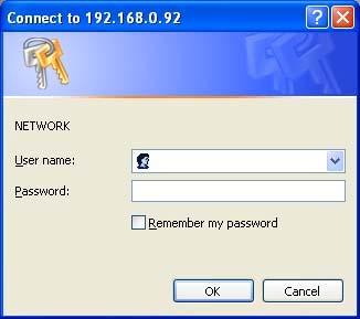
31 Web Configuration pages Connecting the IP camera 1. Start Microsoft Internet Explorer, Mozilla Firefox, Google Chrome, etc. 2. Click on the URL block at the top of the window. 3. Enter the URL address of the IP camera into the URL block and press the Enter button to enter the home page. 4. Enter the "User Name" and "Password" in the appropriate spaces. 5. Select OK. Note The default "User Name" and "Password" are DeviceID and 9999, respectively. The page headlined "Enter Network Password is shown below. Please enter the user name and password of the IP camera when you see it. If either the user name or the password is incorrect, please check the input data and rectify it as necessary. Once authorized successfully, the login page will not appear again until you close the window and reconnect it. The initial sequence of proceeding is to type in your IP address and click the "Enter" button to access the home page. If and when you revise or change data in the "SYSTEM USERS" page, the sequence will alter to initially show the "Enter Network Password" page. 29
32 30
33 Live Video The Live Video from the IP camera is displayed on the home page when your PC is online with the IP camera. There are also additional settings provided on the home page. The AJAX (default) and the ActiveX viewer types display different display formats on their home page. The AJAX viewer type: Non-IE browsers support (for the JPEG mode only). Click to change the pairs of resolution and quality which you already arranged in the Audio and Video setting page (for the JPEG mode). SD card icon: Check if the SD card is inserted or not. When a SD card is inserted, the icon becomes red. Motion-on icon: When there is a detection of motion, the icon will appear in the right upper corner to warn the user. When the motion detection is triggered, the icon will blink red. Status Recording on icon: The icon will appear on the upper right corner. When the recording is triggered, the icon will become red 31 and record the images into the inserted

34 SD card. Alarm on-icon: When there is a detection of external devices such as a sensor, The icon will appear on the upper right corner warn the user. When an alarm is triggered, the icon will blink red. The eptz control panel: Click to start the electronically pan, tilt, and zoom (eptz) within the camera's predefined view area, if one has been defined. SD card icon: Starts the automatic panning function. The ROI will pan from back and forth within the FoV. Motion-on icon: Stops automatic panning. Preset Path: Starts the camera's motion along the predefined path. eptz Speed: You may select a value between 0 and is the slowest and 64 is the fastest. 32

35 Setup The ActiveX viewer type: You can select from the available thumbnails for your option of taking a Snapshot, setting the Storage Folder, selecting the Full Screen mode, Recording, Listen, Talk and Zoom. Snapshot: Click on the button to take a snapshot. The icon will change to a blue color while working effectively. Set Storage Path: Click on the button to set a storage folder for saving the snapshot and the video clips. Full Screen: Click on the button to enter the full screen mode. The icon will change to a blue color while working effectively. Record switch: Click on the button to record a video clip. The icon will change to a blue color while working effectively. Audio switch: Click on the button to start/stop the audio-in function (listen/stop listening). The icon will change to a blue color 33 while working effectively.
36 Talk switch: Click on the button to start/stop audio out function (talk/stop talking). The icon will change to a blue color while working effectively. Digital output: Click on the button to start/stop digital output. The icon will change to a blue color while working effectively. EPTZ: The Digital Zoom mode. The mode utilizes the high resolution feature of the mega pixel camera to simulate the mechanical functions of the PTZ camera. The mode helps the user to filter the image details more efficiently. When the digital zoom mode is active, the image can be zoomed in and out directly. Hold the left key of the mouse and move the mouse in the preferred direction in the Global View area. As the mouse moves, the live view area shows the corresponding image until the border of the image appears. Live Video: Click to go back to the device s homepage. Setup: Click to proceed to the advanced settings. Logout: Click to close the window. Click on the Setup button on the home page to proceed to the advanced settings. 34

37 Wizard To quickly configure your IP Camera, click Wizard on the top of the Setup pages. This wizard will guide you through a step-by-step process to configure your new camera and connect the camera to the Internet. Click Next to continue. Step 1: The IP Camera default setting is DHCP On. Use the DHCP protocol if the DHCP server is working in the LAN. The IP Camera will obtain an IP address automatically from the DHCP server. Or you can turn the DHCP Off to build the IP Camera working environment with a static IP address. The default static IP is You can set an IP address for the IP Camera if the LAN unit isn t connected to a DHCP server. If your Internet Service Provider has provided you with connection settings, or you wish to set a static address within your home network, enter the accurate information for your static IP setting. 35


38 Click Next to continue. Step 2: If you are using PPPoE, select Enable and enter your user name and password, otherwise select Disable and click Next to continue. Step 3: If you have a Dynamic DNS account and would like the camera to update your IP address automatically, Select Enable and enter your host information. Click Next to continue. 36


39 Step 4: Enter a name for your camera and click Next to continue. Step5: Configure the correct time to ensure that all events will be triggered, captured and scheduled at the right time. Click Next to continue. Step 6: If you have selected DHCP, you will see a summary of your camera s settings. Please note down all this information as you will need it for accessing your camera within the network. Click Apply to save your settings. 37

40 Change Image Setting Please follow the steps below to change the video setting through the network as necessary. A preview of the image will be shown in the window of Live Video. Click Submit to activate and save your changes. The Image Setup setting page 1. Click on the Image button to enter the image-setting page. 2. Adjust the Viewer Type. Click to choose the viewer type of the AJAX or ActiveX mode (IE browser only). 38
41 3. Adjust the Image Settings, including Exposure Time, Denoise, Mirror, Flip, White Balance, Brightness, Contrast, Saturation and Sharpness as necessary. 4. Adjust the Device Settings including Device Name and Timestamp. Click Enable OSD to checkmark the box and activate the function. Enter the "Timestamp Label" you have chosen. Enter the "Timestamp Location" you have chosen. 5. Click on the Submit button to submit the new image setting. Description of function keys: Exposure Mode Denoise Mirror: Flip White Balance Brightness Contrast Saturation Sharpness Timestamp Label Timestamp Location Submit Exposure Mode controls a camera by shutter speed and the lens aperture. Auto: Automatic exposure mode. The default shutter time is 1/30~1/10000 (1/25~1/10000) and the maximum gain is 36 db. Indoor: The optimum exposure setting is pre-programmed for the indoor environment. The default shutter time is 1/30~1/120 (1/25~1/100) and the maximum gain is 36 db. Outdoor: The optimum exposure setting is pre-programmed for the outdoor environment. The default shutter time is 1/30~1/750 (1/25~1/750) and the maximum gain is 36 db. Night: The optimum exposure setting is pre-programmed for the night environment. The default shutter time is 1/30~1/750 (1/25~1/500) and the maximum gain is 12 db. Moving: The optimum exposure setting is pre-programmed for moving subjects. The default shutter time is 1/120~1/1,000 (1/100~1/1,000) and the maximum gain is 36 db. Low noise: The optimum exposure setting is pre-programmed to reduce the noise. The default shutter time is 1/8~1/30 (1/7.5~1/25) and the maximum gain is 36 db. Customize 1-3: You can customize an exposure mode by adjusting individual parameters like Gain and Shutter. Schedule: In the Schedule mode, you can set the customize schedule. Select a schedule and set the time period. You can assign one of the exposure modes to be the function mode of the Remaining time. Check and press to Save. Note: The period of the schedule can t be set across midnight. For example, if you want to set a schedule of Night mode from 22:00 to 04:00, you have to (1) check a schedule and select the Night mode and set the period from 22:00 to 24:00, then (2) enable the next schedule and set it to Night mode and set the period from 00:00 to 04:00. Remember to click Save to activate. Denoise (noise reduction) is the process of removing noise from signals. The mirror stores the images reflected by it so it can be used for surveillance or to simply take your own picture. To flip the camera s lens 180 degrees. White balance is the process of removing unnatural shades of color, so that objects which appear white in reality are rendered white in the images. Select your options from Auto, Outdoor, Indoor, Fluorescent and Push Hold. An adjustable setting to compensate for backlit scenes. The measurement for color intensity/strength. This setting controls the strength of colors from black and white to bold colors. An adjustable setting to set the clarity of detail in the images. Enter the timestamp label. Click to open the list of four location modes to choose from: UPPER LEFT, UPPER RIGHT, BOTTOM LEFT, and BOTTOM RIGHT. Click to set. 39

42 The Audio and Video setting page 1. Click on the Audio and Video button to enter the Audio and video page to set the details of the device. You may configure video profiles with different settings for your camera. Hence, you may setup different profiles for your computer and mobile displays. In addition, you may also configure your audio setup for your camera. Click Submit to activate and save your changes. 40
43 2. Select the Profile Number from 1-2. Then set the Aspect ratio of 4:3 or 16:9. Click Save to activate it. 3. Set the Mode, Frame size, Viewer window area, Maximum frame rate and Video quality of the Video Profile as necessary. 4. Set the details of the audio functions. 5. Select 50 Hz or 60Hz of the Power Line. 6. Click on the Submit button to submit the new setting. Description of function keys: Aspect ratio: Mode: Frame size: Viewer window area: Intra Frame Period: Maximum frame rate: Video quality: Audio Settings: Encoding: Audio Mechanism Setting: Enable audio out: Power Line The aspect ratio of an image is the ratio of the width of the image to its height. Select 4:3 or 16:9 of the ratio that best suits your needs. Choose the video format from H.264 or JPEG. In JPEG mode, the video frames are independent. This option allows the user to choose the video resolution of the live view area: 4:3-1024x768, 800x600, 640x480, 480x360, 320x240, 176x :9-1280x720, 800x450, 640x360, 480x270, 320x176, 176x144. This option allows the user to choose the video resolution of the live view area: 4:3-1024x768, 800x600, 640x480, 480x360, 320x240, 176x :9-1280x720, 800x450, 640x360, 480x270, 320x176, 176x144. In the H.264 mode, if there is little motion and most of the video content does not change from frame to frame, the H.264 encoding can compress the video by intra-frame way to keep the quality from loss. You can set the desired time period to use intra-frame compression. Click on the drop-down list to choose the frame rates of 30FPS, 15FPS, 7FPS, 4FPS and 1FPS in all resolution. Selects the image quality level of JPEG images captured from Highest, High, Medium, Low and Lowest. Selects the image quality level of H.264 images captured from Constant bit (4M, 2M, 1M, 512K, 256K, 200K, 128K and 64K) or Fixed Quality (Highest, High, Medium, Low and Lowest). You can use the option to switch the external microphone on/off or adjust the volume. Click on the drop-down list to choose the audio encoding of G.711 and G.726. G.726 offers quality nearly identical to G.711, but it uses only half the bandwidth. Check to activate this function. Then select MIC or Line In. NOTE: The option of 26dB is for long-distance audio receiving, especially longer than 3 meters. Check to activate this function. Then set the Audio out volume level. Select 50 Hz or 60Hz that depends on your local electric utility configuration. Note In order to use the Audio In/ Out signal function, please follow the steps given below. 1. Connect to the camera webpage over the PC IE Browser. 2. Ensure Audio Mechanism Setting & Enable audio out are both selected. Click Submit. 41
44 3. Connect the Mic to the PC, and connect the camera Audio out to the speaker. 4. Select Talk ; speak to the PC-connected microphone. 5. Confirm the sounds made in the camera-connected speaker. 6. Connect the Mic to the camera--audio in; connect the speaker to the PC AUDIO Out. 7. Click Listen in the webpage ; the Mic sends audio signals to the camera. 8. Confirm the sounds from the PC speaker. 42
 on video to specify up to the area(s) on the camera's image to be blocked/excluded from recordings and snapshots. 1.")
45 The Privacy Mask setting page Click on the Privacy Mask button to enter the Privacy Mask Area setting page. Mask 3 privacy area(s) on video to specify up to the area(s) on the camera's image to be blocked/excluded from recordings and snapshots. 1. Click the right mouse button on the video control to show the pop-menu. 2. Press the left mouse button, drag and drop to set the privacy area. 3. Privacy area can be enabled or disabled. 4. After you finish all privacy mask settings, click the Submit button. 43

46 Change the Network Setting Please follow the steps below to change the network setting through the network as necessary. Set the network options and IP address. 1. Click on the Network button in the home page to enter the Network Setup page. 2. The accessible networks here are the PPPoE, Port Detail, Traffic, Dynamic DNS, HTTPS and Access List. 3. Set the details of the LAN Settings for your local area network as necessary. 4. Click on the Submit button to submit the new network setting. Description of function keys: DHCP: DNS Enable UPnP Presentation: Enable UPnP port forwarding: If you have a DHCP server running on your network and would like a dynamic IP address to be updated to your camera automatically. (The Domain Name System) is an Internet service that translates domain names into IP addresses (e.g., ). The address can be obtained from your ISP or network gateway. Enable this setting to allow your camera to be configured as an UPnP device in your network. Enable this setting to allow the camera to add port forwarding entries into the router automatically on a UPnP capable network. 44

47 Change the Network Setting Wireless Setup. The Network page has, on its upper left, the Wireless Setup icon. This section allows you to set up and configure the wireless settings on your camera. You may choose which wireless network for the connection using the pull-down menu of Site Survey or enter the SSID manually. After making any changes, click the Submit button to save your changes. 1. Click on the Wireless Setup button on the upper left menu to enter the Wireless Setup Settings page. 2. Active the Enable Wireless status of the function. Click your choices to enable. 3. Click on the Submit button to submit the new setting. Note Please refer to section PPPoE & DDNS for more details. Description of function keys: Site Survey SSID You can use the drop-down list to select an available wireless network. The related information (SSID, Wireless Mode, Channel, Authentication, Encryption) will be automatically filled in for you. SSID (Service Set Identifier) is the name of your wireless network such as Default, Conference, My network, and etc. Enter the SSID of the wireless access point you wish to use. 45
48 Wireless Mode Channel Authentication Encryption Key: Use the drop-down box to select the mode of the wireless network you wish to connect to. Infrastructure is normally used to connect to an access point or router. Ad-Hoc is usually used to connect directly to another computer. If you are using Ad Hoc mode, select the channel of the wireless network you wish to connect to, or select Auto. Select the authentication you use on your wireless network - Open, Shared, WPA-PSK, or WPA2-PSK. Open: This option makes the camera visible to all devices on the network. No encryption is provided. Shared: Allows communication only with other devices that have the identical WEP (Wired Equivalent Privacy) settings. WPA-PSK, WPA2-PSK: Both modes will require you to input a pre-shared Key for the connection that is held between the camera and the wireless device. If you use WPA-PSK or WPA2-PSK authentication, you will need to specify whether your wireless network uses TKIP or AES encryption. If you use Open or Shared authentication, WEP encryption should be the setting. If you use WEP, WPA-PSK, or WPA2-PSK authentication, enter the Key (also known as password) used for your wireless network. 46
49 Change the Network Setting PPPoE. The Network page has, on its upper left, the PPPoE icon. Please follow the steps below to change the PPPoE setting through the network as necessary. 4. Click on the PPPoE button on the upper left menu to enter the PPPoE Settings page. 5. Active the Enable or Disable status of the PPPoE Settings function. Click your choices to enable. 6. Enter the PPPoE Username and the PPPoE Password, then confirm the password again. 7. Click on the Submit button to submit the new setting. Note Please refer to section PPPoE & DDNS for more details. Description of function keys: PPPoE Setting Username: Password: If you use the camera to connect directly to the Internet, you will need to enter the username and password, which were given to you when you set up your account with your Internet Service Provider. If the camera is behind a router or a gateway, you do not need to configure this setting. Enter it in the given space. Enter it in the required space. 47

50 Change the Network Setting Port Detail. The Network page has, on its upper left, the Port Detail icon. It allows you to specify and reserve the ports for both the HTTP and RSTP streaming. Please follow the steps below to change the Port Detail setting through the network as necessary. 1. Click on the Port Detail button on the upper left menu to enter the Port Detail page. 2. Enter the HTTP port and the Access name for stream for the MJPEG streams of the HTTP. 3. Enter the HTTPS port. The default value is Enter the RSTP port and the Access name for stream for the MJPEG or JPEG streams of the RSTP. 5. Click on the Submit button to submit the new setting. Note If you want to use an RTSP player to access the IP camera, you have to use the following RTSP URL command to request transmission of the streaming data. 48
51 Description of function keys: HTTP Port HTTPS Port RTSP Port HTTP ports allow you to connect to the camera via a standard web browser. This port can be set to a number other than the default HTTP port 80. A corresponding port must be opened on the router. For example, if the port is changed to 8080, users must type in the web browser ' instead of ' HTTPS Port in a camera connects it with a PC via a secure web browser. The port number that you use for RTSP streaming to mobile devices, such as mobile phones or PDAs. You may specify the address of a particular stream. For instance, live1.sdp can be accessed at rtsp://x.x.x.x/video1.sdp where the x.x.x.x represents the IP address of your camera. Note Using a RSTP player to view the video streams (1) Launch the RTSP player. (2) Choose File, and an Open URL dialog box will pop up. (3) Enter an Internet URL to open. The address format is rtsp://<ip address>:<rtsp port>/<rtsp streaming access name for stream1, stream2 or stream3> (4) The live video will be displayed in your player. 49
52 Change the Network Setting Network Traffic. The Network page has, on its upper left, the Traffic icon. Specifying the maximum download/upload bandwidth for each socket is useful when connecting your device to a busy or heavily loaded network. Please follow the steps below to change the setting through the network as necessary. 1. Click on the Traffic button on the upper left menu to enter the Traffic page. 2. Enter the Maximum Upload Bandwidth and the Maximum Download Bandwidth. 3. Click on the Submit button to submit the new setting. Description of function keys: Maximum Upload Bandwidth: Enter it in the given space from a range of 0 to Maximum Download Bandwidth: Enter it in the required space from a range of 0 to Submit: Click to set. 50

53 Change the Network Setting DDNS. The DDNS (Dynamic Domain Name Server) will hold a DNS host name and synchronize the public IP address of the modem when it has been modified. The user name and password are required when using the DDNS service. The Network page has, on its upper left, the DDNS icon. Please follow the steps below to change the DDNS setting through the network as necessary. 1. Click on the Dynamic DNS button on the upper left menu to enter the Dynamic DNS page. 2. Click Enable DDNS to checkmark the box and activate the function. 3. Fill in your dynamic Server Address, Host Name, User Name, Password, Verify Password, Timeout, IP Address and Address. 4. Click on the Submit button to submit the new setting. Note Please refer to section PPPoE & DDNS for more details. Description of function keys: Enable DDNS Function: DNS Server Address: Checkmark to activate the function. (The Domain Name System) is an Internet service that translates domain names into IP addresses (i.e ). The address can be obtained from your ISP or network gateway. Select your Dynamic DNS provider from the pull down menu or enter the server address manually. 51
54 Host Name: User name: Password: Verify Password Timeout: Status: Enter the host name of the DDNS server. Enter your user name or used to connect to the DDNS Enter your password used to connect to the DDNS server. Enter your password again to connect to the DDNS server. Enter the DNS Timeout values for registering the IP address. Indicate the connection status, automatically determined by the system. 52

55 Change the Network Setting HTTPS. The Network page has, on its upper left, the HTTPS icon. Please follow the steps below to change the HTTPS setting through the network as necessary. 1. Click on the HTTPS button on the upper left menu to enter the HTTPS Setting page. 2. Mark the Enable HTTPS secure connection to activate the function. 3. Click to select the Create certificate method from Create self-signed certificate automatically, Create self-signed certificate manually and Create certificate request and install. 4. Click Create to save the create certificate settings. 5. The Certification Information will show below. 6. Click CSR Property to see the Certificate Signing Request information. 7. Click Certificate Property to see the Certificate information. 8. Click Remove to remove the created certificate. 9. Click on the Submit button to submit the new setting. Note The certificate cannot be removed while the HTTPS is still enabled. To remove the certificate you must first uncheck Enable HTTPS secure connection. 53
56 Methods of creating and installing the certificate: 1. Create self-signed certificate automatically Before using HTTPS for communication with the IP camera, a Create self-signed certificate automatically: (1) Enable HTTPS secure connection. (2) Select the Create self-signed certificate automatically option. (3) Click the Create button. (4) The new Certification Information will show in the third column on the HTTPS setting page. (5) Click Home to return to the main page. Change the address from to in the address bar and press Enter on your keyboard. Some Security Alert dialogs will pop up. Click OK or Yes to enable HTTPS. 2. Create self-signed certificate manually (1) Enable HTTPS secure connection. (2) Click Create self-signed certificate manually to open the Create certificate column. (3) Click the Create button. (4) The new Certification Information will show in the third column on the HTTPS setting page. 3. Create certificate request and install (1) Enable HTTPS secure connection. (2) Click Create self-signed certificate automatically to open the Create certificate column. (3) Click the Create button. (4) If you see an Information bar, click OK and click on the Information bar at the top of the page to allow pop-ups. (5) The pop-up windows will show a certificate request. (6) Look for a trusted certificate authority that issues digital certificates. Enroll the IP camera. Wait for the certificate authority to issue a SSL certificate; click Browse... to search for the issued certificate, then click Upload on the Create certificate column. (7) The new Certification Information will show in the third column on the HTTPS setting page. 54

57 Change the Network Setting Access List. The Network page has, on its upper left, the Access List icon. Please follow the steps below to change the Access List setting through the network as necessary. 1. Click on the Access List button on the upper left menu to enter the Access List page. 2. Fill in the Start IP address, End IP address and Delete allow list details of the Allow List. Press the Add button to add or press Delete to erase it. 3. Fill in the Start IP address, End IP address and Delete deny list details of the Deny List. Press the Add button to add or press Delete to erase it. 4. Click on the Submit button to submit the new setting. Description of function keys: Allow List: Start IP Address End IP Address Delete Allow List Deny List: Start IP Address End IP Address Delete Deny List The starting IP Address of the devices (such as a computer) which have permission to access the video of the camera. The ending IP Address of the devices (such as a computer) which have permission to access the video of the camera. Remove the customized setting from the Permission List. The starting IP Address of the devices (such as a computer) which don t have permission to access the video of the camera. The ending IP Address of the devices (such as a computer) which don t have permission to access the video of the camera. Remove the customized setting from the Permission List. 55
58 Note If there are any conflicts between the range of the Allow List and the range of the Deny List, the Access List within the range of the Deny List has the higher priority over the range of the Allow List. For example, the range of the Allow List is set from to and the range of the Deny List is set from to Only users with IPs located between and can access the IP camera. 56
. From this section, you may automatically or manually configure, update and maintain the internal system clock for your camera. 2.")
59 Change the System Setting Please follow the steps below to change the date and time of the system setting through the network as necessary. Set the Time and Date of the system 1. Click on the System button to enter the Time And Date page (default). From this section, you may automatically or manually configure, update and maintain the internal system clock for your camera. 2. To set the Time Configuration, please select your time zone from the drop-down menu. Select this to enable the daylight saving time. Then Select Auto Daylight Saving or Set date and time manually. 3. To set the Automatic Time Configuration, please checkmark Synchronize with NTP Server and enter the address of the NTP Server. 4. To set the Date and Time Manually, please checkmark Set date and time manually. Press Copy Your Computer s Time Settings as necessary to synchronize the time information from your PC or just manually set the date and time from the drop-down lists. 5. Click on the Submit button to submit the new Date and Time settings. 57
60 Description of function keys: Time Zone: Enable Daylight Saving: Auto Daylight Saving: Set date and time manually: Offset: Synchronize with NTP server: NTP Server: Set the date and time manually: Copy Your Computer s Time Settings: Select your time zone from the drop-down menu. Select this to enable the daylight saving time. Select this option so that your camera will configure the Daylight Saving setting automatically. Select this option so that you may configure the Daylight Saving date and time manually. Sets the amount of time to be added or removed when Daylight Saving is enabled. Enable this feature to obtain time configuration automatically from the NTP server. The Network Time Protocol (NTP) synchronizes the device with an Internet time server. Choose the one that is closest to your location. This option allows you to set the time and date manually. This will synchronize the time information from your PC. 58
61 Change the System Setting Digital Input &Output. You may enable the Digital Input (D/I) and Digital Output (D/O) feature and configure the source of events for your camera. 1. Click on the DI and DO button on the left side of the System page to enter the DI and DO page. 2. Select the active state of the Digital Input 1 from the drop-down list. 3. Select the active state of the Digital Output 1 from the drop-down list. 4. Click to set the LED On or Off. 5. Click on the Submit button to submit the new user s setting. Description of function keys: Digital Input: Select N.O. or N.C. as the active state of the Digital Input, in order to use the GPIO connector function. Digital Output: Select N.O. or N.C. as the active state of the Digital Output, in order to use the GPIO connector function. LED Select ON or OFF to use the item, which indicates a camera s status. 59

62 Change the System Setting ICR. Please follow the steps below to change the IR cut function through the network as necessary. 1. Click on the ICR button on the left side of the System page to enter the ICR page. 2. For the IR-Cut Removable filter trigger condition, mark your options from Automatic, Day Mode, Night Mode or Schedule. Click your choices to enable. 3. Mark the IR light power from Off, On, Sync, with ICR or Schedule. Click your choices to enable. 4. Click on the Submit button to submit the new user s setting. Description of function keys: Automatic The Day/Night mode is set automatically. It is normally set in the Day mode and changes to the Night mode in a dark place. Day mode The Day mode disables the IR Cut Filter. Night mode The Night mode enables the IR Cut Filter. Schedule mode Set the Day/Night mode using the schedule. Fill in the time so the Day/Night mode is normally set to Day mode and it enters the Day mode at the start time and returns to the Night mode at the end time. 60

63 Change the System Setting Users. You may modify the name and administrator s password of your camera, as well as add and manage the user accounts for accessing the camera. You may also use this section to create the unique name and configure the OSD setting for your camera. Please follow the steps below to change/add the users authority through the network as necessary. 1. Click on the Users button on the left side of the System page to enter the Users page. 2. Add, modify or delete any user s data if necessary. 3. Click the Add/ Modify User button to submit the new user s settings. 4. Click the Home button to return to the home page. Description of function keys: User List: Delete: Name: Password: Confirm: Authority: Add/ Modify User: The list shows the registered user(s) and the corresponding authority. Deletes a selected user. Enter the user s name, which will be added or modified. Enter the new password of the user s name above. Type in the password again for verification. Choose an authority option of the user s name from: Admin, Operator, and Viewer. Click to submit the new setting to the IP camera. 61

64 Change the System Setting Maintenance. Please follow the steps below to change the system setting through the network as necessary. Click on the Maintenance button on the left side of the Date and Time page to enter the Maintenance page. Description of function keys: Save Configuration Load Configuration Restore Factory Defaults Reboot Device Click on Save Configuration to save the configuration files to the local hard drive. Browse and click on the Load Configuration to load the configuration files to the local hard drive. Click on Restore Factory Defaults to restore the factory defaults. You may browse and load the configuration file. This option will restore the pre-configured or saved settings Click on Reboot Device to reboot the device. This option will restart the camera. 62

65 Change the System Setting Update Firmware. Please follow the steps below to update the firmware through the network as necessary. 1. Click on the Firmware Upgrade button on the left side of the Date and Time page to enter the Firmware Upgrade page. 2. Click on the Browse button to select the UPDATE.BIN file which was copied into your computer. 3. Click on the Upload button. Note DO NOT power off the IP camera while updating firmware. Don t interrupt the process while the unit is updating itself. Please make sure that the UPDATE.BIN file is appropriate to the model of the unit. Updating with the wrong UPDATE.BIN file may cause physical damage to the device. The Temporary Internet Files (or cache) folder contains Web page content that is stored in your hard disk for quick viewing. We suggest deleting the Temporary Internet Files immediately after updating the firmware. To delete the files in the Temporary Internet Files folder, follow these steps: 63
66 1. Quit Internet Explorer and quit any instances of Windows Explorer. 2. Click Start, click Control Panel, and then double-click Internet Options. 3. On the General tab, click Delete Files under Temporary Internet Files. 4. Select the Delete all offline content check box in the Delete Files dialog box, and then click OK. 5. Click OK. 64
67 Change the Application Setting Please follow the steps below to change the application setting through the network as necessary. Change the Application Setting Language Setting. Please follow the steps below to change the Language setting via the network as necessary. 1. Click on the Language button on the left side to enter the Language Setting page. You have an option as to which language to use. 2. Choose your selected language and click Submit to set it. 65

68 Change the Application Setting Motion And PIR. Please follow the steps below to enable changes in the motion detection function of the alarm through the network as necessary. Set the motion detection: 1. Click on the Motion and PIR button on the left side of the Alarm to enter the Motion Detection page. 2. Click and drag the mouse across a targeted zone to draw a rectangle on the image. Note You can set more than one targeted zone depending on your requirement. 3. Enables / disables the motion detection function. 4. Click on the Submit button to submit the new setting of the recording. Description of function keys: Enable Video Motion Select this option to enable motion detection for your camera. Sensitivity The sensitivity bar allows you to specify how much movement is required to trigger the motion detection. Adjusting the percentage allows you to set a requirement on how much of the motion window must be filled by movement. For example: If you set this function at 50%, then Percentage the selected window must be half filled by a moving object before it triggers motion detection. Enable PIR When this option is selected, use PIR (passive infrared) to detect motion. 66

69 Change the Application Setting eptz. This screen allows you to set preset points for the eptz function of the camera, which allows you to look around the camera's viewable area by using a zoomed view. Presets allow you to quickly go to and view a specific part of the area your camera is covering, and you can create preset sequences, which will automatically change the camera's view between the different presets according to a defined order and timing you can set. 1. Click on the eptz button on the left side of the Alarm to enter the Motion Detection page. Description of function keys: Video Profile: eptz Speed: Arrow Buttons and Home Button: This selects which video profile to use. You may select a value between 0 and is the slowest and 64 is the fastest. Use these buttons to move to a specific part of the viewing area, which you can then set as a preset. Click the Home button to return to the center of the viewing area. 67
70 Input Preset Name: Add GoTo Preset List: Preset Sequence: Enter the name of the preset you want to create, then click the Add button to make a new preset. If an existing preset has been selected from the Preset List, you can change its name by typing in a new name, then clicking the Rename button. Using the Pan, Tilt and Zoom (PTZ) controls, move the camera view to the required position and simply by selecting the preset's name. Saves a preset position in the camera. Tests the preset the preset position. Click this drop-down box to see a list of all the presets that have been created. You can select one, then click the GoTo button to change the displayed camera view to the preset. Clicking the Remove button will delete the currently selected preset. This section allows you to create a preset sequence, which automatically moves the camera's view between a set of preset views. A preset sequence is an automated series of camera movements from one preset position to another. A guard tour can be set up to display the video streams from different preset positions in a pre-determined order, and for configurable time periods. Add: Set up a new preset sequence, Modify to change, and Remove to remove an existing preset sequence. 68

71 Change the Application Setting Event. In this section, you can configure and schedule the recording setting for your IP camera. Click on Add to enter the setting pages of the Server, Media, Event and Recording to make the advanced settings. Or click on Delete to erase the settings. The Event Setup page includes 4 different sections: Server, Media, Event and Recording. 1. To add a new item - "event, server or media," click Add. 2. To delete the selected item from the pull-down menu of event, server or media, click Delete. 3. Click on the item name to enter the window for modifying. Note You can add up to five servers, five media fields, three event schedules, and two recording schedules. 69

72 Server: Click on the Add button in the Server column to enter the Server setting page. 1. Enter the Server name, the unique name for a server. There are four kinds of servers supported. They are server, FTP server, HTTP server and network storage. 2. Set the details of the . "Sender address": The address of the sender. "Recipient address": The address of the recipient. 3. Set the details of the FTP. "Remote folder name": An authorized folder on the external FTP server. The string must conform to that of the external FTP server. Some FTP servers cannot accept a preceding slash symbol before the path without virtual path mapping. Refer to the instructions for the external FTP server for details. The folder privilege must be open 70
73 for uploading. "Passive Mode": Check it to enable the passive mode in transmission. 4. Set the details of the Network storage. Only one network storage is supported. "Network storage location": The path to upload the media. "Workgroup": The workgroup for network storage. 5. Click on the SD card to activate the function. Use the SD card for recording media. 6. Click on Submit to save or click on Don t Submit to go back to the Event main page. Server settings: (1) Click Add under the Sever column on Event Settings page to open the Server setting page. On this page, you can specify where the notification has been sent when a trigger is activated. A total of 5 server settings can be configured. Note The maximum server settings amount is five, however, you can set the Network storage or the SD card for only one. (2) Enter the Server Name for the server setting. (3) Select the Server Type. There are four choices of server types available: , FTP, Network storage and SD card. Select one of the server types. Select to send the media files via the when a trigger is activated. (a) (b) (c) (d) (e) (f) Sender address: Enter the address of the sender. Recipient address: Enter the address of the recipient. Server address: Enter the domain or IP address of the server. User name: Enter the user name of the account if necessary. Password: Enter the password of the account if necessary. Port: The default server port is 25. You can also manually set another port. (g) To verify if the setting is correctly configured, click the Test button. The result will be shown in above this setting page (TEST OK or TEST ERROR). If successful, you will receive an indicating the result. (h) Click Submit to activate the setting. 71
74 FTP: Select to send the media files to an FTP server when a trigger is activated. (a) (b) Server address: Enter the domain or IP address of the FTP server. Port: The default FTP server port is 21. It can also be assigned to another port number. (c) (d) (e) User name: Enter the login name of the FTP account. Password: Enter the password of the FTP account. Remote folder name: Enter the folder where the media file will be placed. If the folder name does not exit, the IP camera will create one on the FTP server. (f) Passive mode: Most firewalls do not accept new connections initiated from external requests. If the FTP server supports passive mode, select this option to enable passive mode FTP and allow data transmission to pass through the firewall. (g) To verify if the FTP setting is correctly configured, click the Test button. The result will be shown in above this setting page (TEST OK or TEST ERROR). (h) Click Submit to activate the setting. Network storage: Select to send the media files to a network storage location when a trigger is activated. Please fill in the information for your server. (a) Network storage location: Enter the network storage path (\\ server name or IP address\ folder name). (b) (c) (d) (e) (f) Workgroup: Enter the workgroup name for the network storage server. User name: Enter the user name for the server. Password: Enter the password for the server. Primary WINS server: To verify if the storage setting is correctly configured, click the Test button. The result will be shown in above this setting page (TEST OK or TEST ERROR). (g) Click Submit to activate the setting. 72
75 SD card: Select to send the media files to an SD card when a trigger is activated. (a) (b) Insert your SD card first. To verify if the storage setting is correctly configured, click the Test button. The result will be shown in above this setting page (TEST OK or TEST ERROR). (c) Click Submit to activate the setting. (4) When completed, click Submit to enable the settings to exit this page. The new server settings will appear on the Event Settings page. Note To remove a server setting from the list (Application> Event>), select a server name from the drop-down list and click Delete. Note that only when the server setting is not being applied to an event setting (Application> Event> Event> The Action option) can it be deleted or the camera won t take any action when a trigger is activated. 73

76 Media: Click on the Add button in the Media column to enter the Media setting page. 1. Enter the Media name, the unique name for media. There are three kinds of media: snapshot, video clip and system log. 2. Set the details of the Snapshot. "Source": Select the video source. "Send Pre-event images": The number of pre-event images. "Send Post-event images": The number of post-event images. "File name prefix": The prefix name will be added on the file name of the snapshot images. "Add date and time suffix to file name": Check it to add timing information as file name suffix. 3. Set the details of the Video Clip. "Source": Select the video source. "Pre-event recording": The interval of pre-event recording in seconds. There are two limitations for video clip file. 74
77 "Maximum duration": The maximum recording file duration in seconds. "Maximum file size": The maximum file size would be generated. 4. Click on the System log to activate the function. 5. Click on Submit to save, or click on Don t Submit to go back to the Event main page. Media settings: (1) Click Add under the Media column on Event Settings page to open the Media setting page. On this page, you can specify the type of media that will be sent when a trigger is activated. A total of 5 media settings can be configured. (2) Enter the Media Name for the media setting. (3) Select the Media Type. There are three choices of media types available: Snapshot, Video Clip and System log. Select one of the media types. Snapshot: Select to send snapshots when a trigger is activated. (a) (b) Source: Select to take snapshots from the video profile. Send pre-event image(s) [0~4]: The IP camera has a buffer area; it temporarily holds data up to a certain limit. Enter a number to decide how many images to capture before a trigger is activated. Up to 4 images can be generated. (c) Send post-event image(s) [0~7]: Enter a number to decide how many images to capture after a trigger is activated. Up to 7 images can be generated. Note For example, if both the Send pre-event images and Send post-event images are set to 4, a total of 8 images are generated after a trigger is activated. (d) File Name Prefix: Enter the text that will be appended to the front of the file name. For example, the file name will be in this form: 75
78 Snap_ _ The prefix file name Date and time suffix The format is: YYYYMMDD_HHMMSS (e) Add date and time suffix to file name: Select the option to add the date/ time suffix to the file name. (f) Click Submit to activate the setting. Video Clip: Select to send video clips when a trigger is activated. (a) (b) Source: Select to record video clips from the video profile. Pre-event recording: The IP camera has a buffer area; it temporarily holds data up to a certain limit. Enter a number to decide the duration of recording before a trigger is activated. Up to 4 seconds can be set. (c) Maximum duration: Specify the maximum recording duration in seconds. Up to 100 seconds can be set. NOTE: For example, if pre-event recording is set to 4 seconds and the maximum duration is set to 10 seconds, the IP camera continues to record for another 5 seconds after a trigger is activated. 1 sec. 2 sec. 3 sec. 4 sec. 5 sec. 6 sec. 7 sec. 8 sec. 9 sec. 10sec. Pre-event Recording Trigger Activation Continues to record Maximum recording duration (d) (e) Maximum file size: Specify the maximum file size allowed. File Name Prefix: Enter the text that will be appended to the front of the file name. (f) Click Submit to activate the setting. 76
79 System log: Select to send a system log when a trigger is activated. Click Submit to activate the setting. (4) When completed, click Submit to enable the settings to exit this page. The new media settings will appear on the Event Settings page. Note To remove a media setting from the list (Application> Event>), select a media name from the drop-down list and click Delete. Note that only when the media setting is not being applied to an event setting (Application> Event> Event> The Attached media item) can it be deleted or you can t get the images/ logs when a trigger is activated. 77

80 Event: Click on the Add button in the Event column to enter the Event setting page. 1. Enter the Event name. Checkmark the Enable this event box and activate the function. Then set the Priority and the Source from the drop-down list. "Priority": The event with higher priority will be executed first. 2. Select the event trigger mode. "Video motion detection": Select the windows which need to be monitored. "Periodic": The event is triggered in specified intervals. The unit of trigger interval is a minute. "Digital input": The event is triggered when the DI status is changed by an external device. "System boot": The event is triggered when the system boots up. "Network Loss": The event is triggered when the network disconnect. 78
81 3. Set the recording schedule time. 4. Set the Trigger D/O of activating the action. Check it to trigger digital output for specific seconds when an event is triggered. 5. Click on Submit to save or click on Don t Submit to go back to the Event main page. Event settings: (1) Click Add under the Event column on Event Settings page to open the Event setting page. On this page, you can arrange three parts Trigger, Event Schedule, and Action to set an event. A total of 3 event settings can be configured. (2) Enter the Event Name for the event setting. (3) Select Enable this event option to enable the event setting. (4) Set the event priority from: normal, high and highest. Events with a higher priority will be executed first. (5) Enter the duration in seconds to pause motion detection after a motion is detected (for the trigger types - motion detection and digital input use only). (6) An event is an action initiated by a user-defined trigger source; it is the causal arrangement of the following three parts: Trigger, Event Schedule, and Action. Set the event details of each part. Trigger: This option defines when to trigger the IP camera. The trigger source can be configured to use the IP camera s built-in motion detection mechanism, periodic, external digital input devices or system boot. There are several choices of trigger sources as shown below. (a) Video motion detection: This option makes use of the built-in motion detection mechanism as a trigger source. To enable this function, you need to configure a motion detection windows first. Note For example, when the event status is on, once an event is triggered by motion detection, the IP Camera will automatically send snapshots, video clips or System log via the server type as your settings. (b) Periodic: This option allows the IP camera to trigger periodically for every 79
82 other defined minute(s). UP to minutes. (c) Digital input: This option allows the IP camera to use an external digital input device or sensor as a trigger source. Depending on your application, there are many choices of digital input devices on the market which helps to detect changes in temperature, vibration, sound, and light, etc. (d) System boot: This option triggers the IP camera when the power to the IP camera is disconnected. (e) Network Loss: This option triggers the IP camera when the network to the IP camera is disconnected. Event Schedule: Specify the period for the event. (a) (b) Select the days of the week. Set the recording schedule in the 24-hour time format. Action: Define the actions to be performed by the IP camera when a trigger is activated. (a) Trigger D/O for ~ seconds: Select this option to turn on the external digital output device when a trigger is activated. Specify the length of the trigger interval in the text box. (b) If you want to set an event with recorded video or snapshots, it is necessary to configure the server and media settings first so that the IP camera will know what action to take (such as which server to send the media files to) when a trigger is activated. Checkmark the one of the Server Names which you have set already, then select the Attached media (the media name) from the drop-down list. (7) When completed, click Submit to enable the settings to exit this page. The new event settings will appear on the Event Settings page. Note The new event settings / server settings / media settings will appear in the event drop-down list on the Application> Event> page. 80

83 Recording: Click on the Add button in the Recording column to enter the Recording setting page. 1. Enter the Recording entry name. Checkmark the Enable this recording box and activate the function. Enable this option if you want to upload the recording to a shared folder in the network. Then set the Priority and the Source from the drop-down list. 2. Set the recording schedule time. Select the day(s) according to when you want the camera to make a video clip. 3. Set the details of the recorded file. "Always": This enables the camera to make video clips continuously. "From": The time range specified for the video clip. 4. Click on Submit to save or click on Don t Submit to go back to the Event main page. 81
84 Record settings: (1) Click Add under the Record column on Event Settings page to open the Record setting page. In this page, you can define the recording source, recording schedule and recording capacity. A total of 2 recording settings can be configured. (2) Enter the Record entry name for the event setting. (3) Select Enable this recording option to enable the recording setting. (4) Select the recording priority from: normal, high and highest. Recording with a higher priority will be executed first. (5) Select the recording source from the drop-down list (profiles). (6) Specify the recording schedule and the recording settings. Recording Schedule: (a) (b) Select the days of the week. Set the recording schedule in the 24-hour time format. Recording Settings: (a) Destination: You can select the SD card or SAMBA (Network storage) that was set up for the recorded video files. (b) Total cycling recording size: When the maximum capacity is reached the value you set, the oldest file will be overwritten by the latest one. The reserved amount is reserved for cyclic recording to prevent malfunction. The limited value is 200~ Mbytes. (c) Size of each file for recording: Set the maximum file size of each recording video files. (d) File Name Prefix: Enter the text that will be appended to the front of the file name. (7) When completed, click Submit to enable the settings to exit this page. The new media settings will appear on the Event Settings page. 82

85 Change the Storage Setting Please follow the steps below to change the SD card setting through the network as necessary. Change the SD card Setting. Please follow the steps below to change the setting via the network as necessary. 1. Click on the storage button at the top of the Setup page to enter the SD Card screen. 2. The SD Card page contains two image modes, the Video and the Picture. 3. Click Video or Picture to enter its sub year-month folder. 4. Click to enter its sub date folder. 5. Click the desired file to display the images therein. 6. Each file can be deleted by checking and pressing the OK button. 83
86 Status The device information. This page displays all the information about your device and network connection. Click on the Device info button of the Status page to enter the Device info screen. 84

87 The device information. This page displays the log information of your camera. 1. Click on the Device info button of the Status page to enter the Device info screen. 2. Click on the Clear to erase all of the logs. You may also download the information by clicking Download. 85
88 PPPoE & DDNS Using the PPPoE 1. Install the XDSL software (obtained from your ISP dealer) in your PC. 2. Search your IP camera's IP address: you can connect the IP camera and the Video monitor. The monitor screen will show the IP address on its right side. 3. Turn off the DHCP function (of the IP camera) if it is ON. 4. Installing an IP address in your PC or notebook. Desktop Move the mouse focus to the Network neighborhood and click the right key of the mouse Choose the properties Choose your local connection Choose the properties and select the configuration Select the TCP / IP Choose the properties Enter the IP address in a four-part formula, for example (the first three parts must be identical to the above numbers, only the last part can be changed to your own number, which must never exceed 255) Click on the mask and the mask input, namely (a fixed formula) Click OK Click OK. 5. Desktop Choose IE browser Enter the IP camera IP address in the URL (check step # 2 above) Enter IP camera images will appear. PPPoE Settings 1. Enter the IP camera home page Choose the network Enter User Name: Device ID and Password: 9999 Click OK. 2. Choose PPPoE PPPoE mode: Select ON Enter Account Enter Password Submit Unplug the power connection. 3. Plug in the IP camera and it will receive an IP address from the ISP dealer (this IP address is dynamic --- every time you unplug and plug in again you ll get a new IP address). Test: Go to the Internet. 1. Set your PC to enter the Internet. 86
89 2. Desktop IE browser Enter the IP camera IP address (the same address as in the PPPoE settings and step 3 above) You can see the IP camera images. DDNS settings 1. Check your IP camera s IP address (monitor) open your IE browser Use the address to connect to the IP camera or view the images Choose the network Enter User name : DeviceID and Password : 9999 Click OK. 2. Choose the DDNS Click Enable DDNS Enter the DDNS host name, for example abc123. homeip.net Enter DDNS Account, for example abc123 Enter the DNS Password, for example 7777 Submit The settings are now complete Close the IE browser. 3. Open the IE browser again Enter the Website address you just applied for, such as abc123.homeip.net You can look at your IP camera images right away. The procedure is complete. Note These settings are only for your ADSL Dynamic IP configuration. If your configuration is fixed (true IP), you don t need to proceed with the PPPoE and DDNS settings. The DDNS is just for your convenience. 87
90 6 FREQUENTLY ASKED QUESTIONS Question 1: How do I view live images of the IP camera via the Internet Explorer on a Desktop PC or a laptop computers in a situation where there are no monitors? To get the IP address of the IP camera without a monitor, use one of the following two methods to get the IP address: UPnP. UPnP: Please refer to APPENDIX 1. Question 2: How do I activate UPnP? 1. Follow the default settings to set up the related settings, and connect the hardware. 2. Activate the Web browser and enter the IP camera s URL. 3. SETUP Network button. 4. Select Enable UPnP presentation. 5. Select Enable UPnP port forwarding ; make the Forwarding Port setting. Note 1. Follow step 4 above then turn on computer s My Web Neighbors and find the IP camera. Then click to go to the IP camera s home page. 2. Follow step 5 above and make the Route UPnP port forwarding setting. 3. Your computer can access an IP camera through a router by opening a port on the router (port forwarding) if the router is configured to a specific port. For example port 8080, you can enter the IP address as on the URL entry box of the web browser to access the IP camera. Question 3: How to change the Video Profiles 1 & 2? On Live page click Profiles 1 & 2. Question 4: How do I set up the motion detection area and its sensitivity? 1. Go to SETUP Application button Motion Detection button. 2. Select Enable Video Motion. 3. Set up the target zone and setup the Sensitivity and Percentage. 4. Click the Submit button to submit the setting. 5. When a person or object moves within the target zone under a setting, the Motion Detection 88
91 will display the response signal in the Live Video and Video Out. Question 5: How do I use the DynDNS to connect the IP camera by using its Sub Hostname via the intranet? Set the DDNS function 1. Click the Network button on the home page. 2. Click the Dynamic DNS button on the left side of the page to enter the Dynamic DNS page. 3. Click Enable DDNS to activate. 4. Enter the DDNS Host Name, DDNS Account and DDNS Password which you created in the website. 5. Click the Submit button to save the settings. Set the PPPoE function 1. Click the Network button on the home page. 2. Click the PPPoE button on the left side of the page to enter the PPPoE page. 3. Choose Enable to activate the function. 4. Enter the Account and the Password which are provided by your ISP. 5. Click the Submit button to save the setting. Use the Sub Hostname to view the IP camera 1. Click the URL block at the top of the computer screen. 2. Enter the DDNS Host Name of the IP camera into the URL block and press the Enter key to enter the login page. 3. Enter the user name and password. 4. Click the OK button and enter the home page of the IP camera. Question 6: How do I add or modify the users and their authority to use the IP camera? Entering the setting page 1. Click the System button in the Setup page. 2. Click the User button on the left side of the page to enter the USER page. Add a new user 1. Enter the user name, the password, the confirmed password and choose the authority level. There are three levels of authority: Admin, Operator and Viewer. Admin: The user who accesses with the admin name and password has the full rights to change the settings of the IP camera. Operator: Has access to viewing and functionality. Viewer: Has limited viewing rights. 2. Click the Add/Modify User button to submit the new user setting. 89
92 Modify the user 1. Click the user name you want to modify from the USER LIST. 2. Enter the password, the confirmed password and choose authority level. 3. Click the Add/Modify User button to submit new setting. Delete a user 1. Click the user name you want to delete from the USER LIST. 2. Click the Delete User button. Question 7: How do I create the self-signed certificate manually? 1. Go to Setup Network button HTTPS button 2. Select Enable secure HTTPS connection. 3. Create certificate settings Create self-signed certificate manually Create. 4. Fill in the relevant data in the text boxes titled Country, State or province, Locality, Organization, Organization Unit, Common Name & Validity; click Create. Question 8: How do I download the log list? 1. Click Setup Status Log. 2. The display will show the log list page. 3. Click First Page, Previous 20 or Next 20 to view the recording list. 4. Click Download; select the file path, and download the recording list. 90
93 7 SPECIFICATIONS Model Camera Image Audio Network Lens Minimum illumination IR cut filer Day & Night Video Compression Resolution Frame Rate Video streaming Profiles Image settings Video management software Audio streaming Compression Audio bit rate Inputs / outputs: Security Wireless Protocols Users Firmware update LC-6760 Fixed Focal Board Lens f:3.6mm F2.0. Color: 1.0 lux, B/W: 0.5 lux. Yes Auto / Day / Night / Schedule. H.264 / MJPEG. - 4:3 : 960x720, 800x592, 640x480, 480x360, 320x :9 : 1280x720, 800x448, 640x360, 480x272, 320x176. NTSC: Maximum 30FPS (1280x720). PAL: Maximum 25FPS (1280x720). - Simultaneous H.264 and MJPEG. - Multi-profile: resolution / compression / frame rate / video quality. 2 (selectable) - Adjustable image size, quality, and bit rate. - Flip & Mirror. - AGC, AWB. - Time stamp and text caption overlay. - Privacy masks. - Exposure Mode. SDK, including HTTP-API / ActiveX / ONVIF. Two-way. G.711u G.711u 64kbps Build-in Microphone & Speaker (5M). Multi-level password protections, IP address filtering, HTTPS encryption, User access log. IEEE b/n/g IPv4, HTTPS, HTTP, TCP, UDP, RTP/RTCP/ RTSP, DHCP, NTP, FTP, SMTP, UPnP, ICMP, ARP, DDNS, PPPoE, SAMBA. Access by 10 simultaneous users. SD card / HTTP. 91
94 Alarm Connectors General Recording Pre-alarm recording SD card, SAMBA, FTP Yes. Advanced motion 512 zones. Sensitivity: %. Trigger Notification RJ-45 Digital I / O DC jack Reset Local storage device LED indicators Buttons Power consumption Motion Detection Schedule Alarm input Ethernet loss SD card recording, SMTP, FTP, HTTP, alarm output. 10 BASE - T / 100 BASE -TX. 4 pin-contact terminal block (DO, DI, 5V, GND) ψ6.5x2.0. Reset for factory default. Micro SD card slot Network / Power/ WPS Reset/ WPS 10W Power - 5V DC ( DC power jack ). Approx. 4 W. OS Linux 2.6 kernel. Operating conditions -0 to 40 ( 32 to 104 ) Approval Dimensions CE, FCC, RoHS. 130 x 80 x 107 mm. Package Weights 550g. Accessories included - Quick Installation Guide. - CD x 1 ( includes CMS & User's Manual ). - Power adapter: (Input: VAC, 50 / 60 Hz, Output: 5VDC, 1.2A). - RJ-45 cable x 1 * Design and specifications are subject to change without notice. 92
95 Appendix: The Playback Utility Tool-- CMS This section provides instructions for installing and using the CMS which is included with the device. Introduction to the CMS The CMS allows you to access many units of the device from a remote desktop or a laptop in a TCP/IP networking environment. It can perform the following functions. The recorded data of the camera will be automatically downloaded to the user s computer for backup. Views live images in a smooth sequential flow from an IP camera. Stores, searches, and reviews recorded video from a PC or an SD card quickly. Note Before you view images from a desktop, you need to have your device networked by obtaining a 10/100 base-tx Ethernet data cable (Standard RJ-45) to connect the device to your LAN/WAN. Now enter the main menu to set the IP address. Install the CMS in your PC Install the CMS from the supported CD-R. 1. Exit all applications currently running in the selected PC. 2. Insert the supported CD in the CD-ROM drive. The program will execute the installation automatically. Follow the on-screen instructions to proceed with the rest of the installation procedure as they appear. 3. After the installation is complete, pop up the START menu from your computer, and point to Programs / CMS / CMS to open up the program selection page as shown below. Click on the CMS tag to start the CMS program. 93

96 Start to use the CMS Once the connection has been established, the software will discover the connection of the devices in the LAN. The Device Auto Scan screen will display the connection of the all-type device. Please enter the password and click OK to add the new device. 94

97 View the video from a remote PC Use the CMS to browse the video from a remote location. Search and add a new camera The user can manually add a new connection of the camera in the LAN. 1. Click the Setup button to open the Setting window. 2. Click Rescan, then select and drag the camera into the quad-monitoring area. Click OK to confirm. Note You can use the mouse to switch from one image to another. Note You can remove the devices by drugging and dropping them into the recycle bin icon. 95
.")
98 Operation Live View Once the connection has been established, you will see the Live View window (see the sample screen below). 96
99 1. The live view area. Note Pop-menu: You can use the mouse to move to each channel. Click the right key of the mouse to show a window. You can select "Full Screen", "Capture" or Print. Double-click the red frame live-viewing window to switch between single or quad channel modes. 2. Select the division mode of the live view area: Single View, Quad View, Actual View and Full Screen. 3. You can switch between these modes by clicking the Live View and Playback buttons. 4. The camera list. 5. Click the Setup button to open the Setting window. 6. Shows current local time and date. 7. The audio function: Click the audio icon to play the live audio and click once again to deactivate. Use the scroll bar to control the volume. 8. Click to minimize the window or turn off the software. 97

100 Playback The Playback window (see the sample screen below). 1. The display area. Note Pop-menu: You can use the mouse to move to each channel. Click the right key of the mouse to show a window. You can select "Full Screen", "Capture" or Print. 2. Select the division mode of the live view area: Single View, Quad View, Actual View and Full Screen. 3. You can switch between these modes by clicking the Live View and Playback buttons. 4. The system will search for a recorded video stored in the device. The dates marked in blue color indicate there are record videos on those days. 5. Click the Setup button to open the Setting window. 6. Shows current local time and date. 7. The audio function: Click the audio icon to play the playback audio and click once again to 98
101 deactivate. Use the scroll bar to control the volume. 8. The playback function bar. 9. You can click or pull the indicator on the scroll bar to the point you want to see. 10. Click to minimize the window or turn off the software. Settings Press the Setup button to enter the Setting page. Camera Setting Searching for Cameras The user can manually add a new connection of the camera in the LAN. 1. Click the Setup button to open the Setting window. 2. Click Rescan, then select and drag the camera into the quad-monitoring area. Click OK to confirm. 99


102 PIR Detection Select the camera from the list to activate its PIR detection function. Click OK to confirm. Motion Detection 1. Select the camera from the list to activate its motion detection function. 2. Click and drag the mouse across a targeted zone to draw a red rectangle on the image. Every cell in the grid represents a detection area. 3. Click OK to confirm. Note Click the right key of the mouse to show a window. You can select "Select all", "Clear all" or Restore. 100

103 Storage Setting Set the directory for saving the recording data. You can set the reserved hard disk space by using the scroll bar. Click on the OK button to submit the new setting of the storage setting. Note The recorded data of the camera will be automatically downloaded to the user s computer for backup. The software will check the latest recorded date every two minutes and download the data automatically. When the recording data limit is reached, the new data will overwrite the oldest one. 101

104 General Setting Language You have an option as to which language to use. Choose your selected language from the drop-down list. Log This page displays the log information of your camera. Click on the Clear to erase all of the logs. You may also download the information by clicking Save as. 102
INSTALLATION & OPERATION MANUAL DDK-1800BC. Fixed Indoor/Outdoor IP Bullet Camera
 INSTALLATION & OPERATION MANUAL DDK-1800BC Fixed Indoor/Outdoor IP Bullet Camera Table of Contents SAFETY PRECAUTIONS...4 1. DESCRIPTION...6 1.1 PHYSICAL DESCRIPTION...6 1.2 THE RESET BUTTON...8 1.3 ALARM
INSTALLATION & OPERATION MANUAL DDK-1700BC. Fixed Indoor/Outdoor IP Bullet Camera
 INSTALLATION & OPERATION MANUAL DDK-1700BC Fixed Indoor/Outdoor IP Bullet Camera Table of Contents SAFETY PRECAUTIONS... 4 1. DESCRIPTION... 6 1.1 PHYSICAL DESCRIPTION... 6 1.2 THE RESET BUTTON... 7 1.3
2.0 Mega-Pixel IP Camera
 INSTALLATION & OPERATION MANUAL 2.0 Mega-Pixel IP Camera IP Box Camera Fixed IP Indoor Mini-dome Fixed IP Outdoor Mini-dome Bullet IP Camera Indoor/Outdoor Before trying to connect or operate this product,
Table of Contents. Product Overview...4 Package Contents...4 System Requirements Hardware Overview...5 Front... 5 Rear...6 Side...
 Product Overview...4 Package Contents...4 System Requirements... 4 Hardware Overview...5 Front... 5 Rear...6 Side...7 Installation...8 Starting the Camera Installation Wizard... 8 Connecting Wirelessly
INSTALLATION & OPERATION MANUAL. Before trying to connect or operate this product, please read this manual completely
 INSTALLATION & OPERATION MANUAL Mega-Pix Box IP Camera Before trying to connect or operate this product, please read this manual completely Table Of Contents SAFETY PRECAUTIONS...3 1. PRODUCT FEATURES...4
Table of Contents. Product Overview...4 Package Contents...4 System Requirements Hardware Overview...5 Front... 5 Rear...6 Side...
 Product Overview...4 Package Contents...4 System Requirements... 4 Hardware Overview...5 Front... 5 Rear...6 Side...7 Installation...8 Starting the Camera Installation Wizard... 8...9 Using the Menu...
XIPLED Software User s Manual. For Firmware release V3.5.0.*
 XIPLED1080-36 Software User s Manual For Firmware release V3.5.0.* Product name: XIPLED1080-36 Release Date: 2014/10/02 Manual Revision: V02 Feature XIPLED1080-36 Live View All Series Camera/Video/Audio
C1002 IP Camera. Quick Installation Guide. Solwise Ltd., 1
 C1002 IP Camera Quick Installation Guide Solwise Ltd., www.solwise.co.uk, sales@solwise.co.uk 1 Trademarks and/or registered trademarks are the property of their respective owners The information presented
1.3 CU-720PIR. 720P PIR Passive PoE Night Vision IPCAM. All-in-One Security Solution IP Camera
 CU-720PIR 720P PIR Passive PoE Night Vision IPCAM 30fps at 1.3 MegaPixel Mode 30fps at 720P High Definition Mode 24V Passive PoE Port Built-in PIR Sensor 10 Meter IR Night Vision LED with ICR Low Lux Sensor
1.3 CU-720PIR PIR. 720P PIR Passive PoE Night Vision IPCAM. All-in-One Security Solution IP Camera
 CU-720PIR 720P PIR Passive PoE Night Vision IPCAM 30fps at 1.3 MegaPixel Mode 30fps at 720P High Definition Mode 24V Passive PoE Port Built-in PIR Sensor 10 Meter IR Night Vision LED with ICR Low Lux Sensor
Wireless Day / Night PTZ Cloud Camera TV-IP851WIC (v1.0r)
") (v1.0r) TRENDnet s Wireless N Day / Night PTZ Cloud Camera, model, takes the work out of viewing video over the internet. Previously to view video remotely, users needed to perform many complicated and
(v1.0r) TRENDnet s Wireless N Day / Night PTZ Cloud Camera, model, takes the work out of viewing video over the internet. Previously to view video remotely, users needed to perform many complicated and
Wireless Day / Night Cloud Camera TV-IP751WIC (v1.0r)
") (v1.0r) TRENDnet s Wireless Day / Night Cloud Camera, model, takes the work out of viewing video over the internet. Previously to view video remotely, users needed to perform many complicated and time
(v1.0r) TRENDnet s Wireless Day / Night Cloud Camera, model, takes the work out of viewing video over the internet. Previously to view video remotely, users needed to perform many complicated and time
1. Introduction Overview Product Information... 3
 1. Introduction... 3 1.1 Overview... 3 1.2 Product Information... 3 2. Device Connection... 3 2.1 Connection Diagram... 3 2.2 Wi-Fi Setting... 4 2.2.1 Set up WiFi by Mobile Phone... 4 2.2.2 WPS/QSS One
Wireless PTZ Cloud Camera TV-IP851WC (v1.0r)
") (v1.0r) TRENDnet s Wireless PTZ Cloud Camera, model, takes the work out of viewing video over the internet. Previously to view video remotely, users needed to perform many complicated and time consuming
(v1.0r) TRENDnet s Wireless PTZ Cloud Camera, model, takes the work out of viewing video over the internet. Previously to view video remotely, users needed to perform many complicated and time consuming
NS15WG 1080P Web App User Manual
 NS15WG 1080P Web App User Manual Table of Contents 1. Getting Started... 4 Download the Web App...4 2. Web App Top Menu... 5 Live Video...6 Video Playback...6 Settings...6 3. Device Configuration... 6
Megapixel PoE Day / Night PTZ Internet Camera TV-IP672PI (V1.0R)
") Megapixel PoE Day / Night PTZ Internet Camera (V1.0R) The Megapixel PoE Day / Night PTZ Internet Camera, model, provides day and night security over a large area. Pan the camera side-to-side a remarkable
Megapixel PoE Day / Night PTZ Internet Camera (V1.0R) The Megapixel PoE Day / Night PTZ Internet Camera, model, provides day and night security over a large area. Pan the camera side-to-side a remarkable
Quick Install Guide. Model: PLC-223W, PLC-233W
 Quick Install Guide Model: PLC-223W, PLC-233W This installation guide provides basic instructions for installing the PLC-213W/ PLC-223W/PLC-233W indoor wireless IP camera on your network. By following
VIP2C1N / VIP2C1P HD Mini Cube Network Camera
 Quick Installation Guide VIP2C1N / VIP2C1P HD Mini Cube Network Camera Please read this manual thoroughly before use, and keep it handy for future reference. 1. Description The Network Camera supports
IP WEB User Manual V2.0
 IP WEB User Manual V2.0 Please read carefully before installing or contacting your supplier. The information contained at the time of printing is correct, but is subject to change without notice. This
HooToo IP Camera User Manual(part two)
") HooToo Inc. HooToo IP Camera User Manual(part two) For Model: HT-IP210P Published by SunvalleyTek Group 2014/9/14 Content 1. IPCamClient (windows software)...3 Set up...3 CAM... 13 Local Setting... 13
HooToo Inc. HooToo IP Camera User Manual(part two) For Model: HT-IP210P Published by SunvalleyTek Group 2014/9/14 Content 1. IPCamClient (windows software)...3 Set up...3 CAM... 13 Local Setting... 13
1.3 CW x720 Pixels. 640x480 Pixels. 720P Wireless 150Mbps IPCAM. High Quality 720P MegaPixel Image
 CW-720 720P Wireless 150Mbps IPCAM 30FPS at 1.3 Mega Mode 30FPS at 720P Mode 150Mbps Wireless-B/G/N Use 10X Times Less Storage with H.264 Video Compression Micro SD Card Slot for Local Storage ios and
Contents. Introduction Overview Range of Application Product Description Operation Environment...
 Contents Introduction... 3 1. Overview... 4 1.1 Range of Application... 4 1.2 Product Description... 4 1.3 Operation Environment... 5 2. Device Connection... 5 3. Device Operation Instructions... 6 3.1
User Manual. Wireless IP Camera
 User Manual Wireless IP Camera Introduction Hi. Thank you for purchasing the AUKEY VT-CM1 Wireless Security IP Camera. Please read this user manual carefully and keep it in a safe place for future reference.
Cisco WVC210 Wireless-G Pan Tilt Zoom (PTZ) Internet Video Camera: 2-Way Audio Cisco Small Business Video Surveillance Cameras
 Internet Video Camera: 2-Way Audio Cisco Small Business Video Surveillance Cameras") Cisco WVC210 Wireless-G Pan Tilt Zoom (PTZ) Internet Video Camera: 2-Way Audio Cisco Small Business Video Surveillance Cameras High-Quality, Flexible, Remote-Controlled Wireless Video Solution for Your
Cisco WVC210 Wireless-G Pan Tilt Zoom (PTZ) Internet Video Camera: 2-Way Audio Cisco Small Business Video Surveillance Cameras High-Quality, Flexible, Remote-Controlled Wireless Video Solution for Your
Smart Home System Kit
 Smart Home System Kit IP SECURITY ALARM SERIES More information, please visit the online CD information on the website http//netcam360.com 0 P a g e BRIEF INSTRUCTION 1. Start Infrared box camera a. Install
Mega-Pix IP Fixed Dome
 INSTALLATION & OPERATION MANUAL Mega-Pix IP Fixed Dome Before trying to connect or operate this product, please read this manual completely Table Of Contents SAFETY PRECAUTIONS...3 1. PRODUCT FEATURES...4
Version /11/2013. User Manual. HD Wireless N Cube Network Camera DCS-2132L
 Version 2.00 27/11/2013 User Manual HD Wireless N Cube Network Camera DCS-2132L Preface D-Link reserves the right to revise this publication and to make changes in the content hereof without obligation
Wireless N Day / Night Internet Camera TV-IP551WI (v1.0r)
") The, model TV- IP551WI, transmits real-time video over the Internet. Record crisp video in complete darkness for distances of up to 7.5 meters. Wireless n technology provides unsurpassed wireless coverage
The, model TV- IP551WI, transmits real-time video over the Internet. Record crisp video in complete darkness for distances of up to 7.5 meters. Wireless n technology provides unsurpassed wireless coverage
F Series Robot Model IP Camera V2.3 User Manual
 F Series Robot Model IP Camera 2010-5 V2.3 User Manual Index 1 INTRODUCTION... 4 2 FUNCTION AND FEATURES... 4 3 APPEARANCE AND INTERFACE... 5 3.1 APPEARANCE... 5 3.2 INTERFACE OF EQUIPMENT... 6 4 NETWORK
Wireless Pan & Tilt Camera
 User Manual Wireless Pan & Tilt Camera CIPCAMPTIWL v1.0 Index 1 INTRODUCTION... 4 1.1 THE PACKAGE INCLUDES... 4 1.2 FUNCTION AND FEATURES... 4 1.3 TECHNICAL SPECIFICATIONS... 4 2 APPEARANCE AND INTERFACE...
IP Camera. Apr 2012 V
 H Series with Pan/Tilt Mega pixel IP Camera Apr 2012 V1.4.0.1.4 User Manual Index 1 INTRODUCTION... 4 1.1 THE PACKAGE INCLUDES... 4 1.2 FUNCTION AND FEATURES... 4 1.3 TECHNICAL PARAMETERS... 5 2 APPEARANCE
Table Of Contents SAFETY PRECAUTIONS PRODUCT FEATURES DESCRIPTION OF THE FRONT/REAR VIEW INSTALLATION...8
 Table Of Contents SAFETY PRECAUTIONS...2 1. PRODUCT FEATURES...3 1.1 PRODUCT INTRODUCTION...3 1.2 PRODUCT FEATURES...4 2. DESCRIPTION OF THE FRONT/REAR VIEW...6 2.1 FRONT PANEL AND REAR PANEL...6 2.2 TERMINAL
NSC18-WN Pan/Tilt Network Camera 1.3 Megapixel CMOS, 300 Mbps Wireless n, Motion-JPEG + MPEG4, Audio, SD Card Part No.
 NSC18-WN Pan/Tilt Network Camera 1.3 Megapixel CMOS, 300 Mbps Wireless 802.11n, Motion-JPEG + MPEG4, Audio, SD Card Part No.: 550857 The INTELLINET NETWORK SOLUTIONS SOHO Network Camera, Model NSC18-WN,
2.01 N : D1 resolution 37x Zoom Outdoor Network Vandal-proof PTZ Security Camera
 PART 1 - NOT USED PART 2 - PRODUCTS 2.01 N5013-37: D1 resolution 37x Zoom Outdoor Network Vandal-proof PTZ Security Camera A. Functional Description The specified product shall be an all-in-one style outdoor
Cisco WVC210 Wireless-G Pan Tilt Zoom (PTZ) Internet Video Camera: 2-Way Audio Cisco Small Business Video Surveillance Cameras
 Internet Video Camera: 2-Way Audio Cisco Small Business Video Surveillance Cameras") Cisco WVC210 Wireless-G Pan Tilt Zoom (PTZ) Internet Video Camera: 2-Way Audio Cisco Small Business Video Surveillance Cameras High-Quality, Flexible, Remote-Controlled Wireless Video Solution for Your
Cisco WVC210 Wireless-G Pan Tilt Zoom (PTZ) Internet Video Camera: 2-Way Audio Cisco Small Business Video Surveillance Cameras High-Quality, Flexible, Remote-Controlled Wireless Video Solution for Your
Table of Contents. Product Overview...4 Package Contents...4
 Product Overview...4 Package Contents...4 Hardware Overview...5 Hardware Overview...5 Rear...5 Front... 6 Configuration with Wizard... 9 Configuration...14 Web-based Configuration Utility... 14 D-ViewCam
IS-DM320, HB User Manual. Ver 1.0
 IS-DM320, HB User Manual Ver 1.0 Sentry360 2014 Table of Contents 1. Overview... 3 1.1 Features... 3 1.2 Package Contents... 4 1.3 Dimensions... 5 1.4 Connectors... 6 2. Camera Cabling... 7 2.1 Connect
Full HD WDR Mini Dome IP Camera
 Full HD WDR Mini Dome IP Camera User s Manual DN-16086 Ver. 1.0 Table of Contents 1. Overview... 2 1.1 Features... 2 1.2 Package Contents... 3 1.3 Dimensions... 4 1.4 Installation... 5 1.5 Connectors...
Do not place or mount Ocli 1 in an area where it will be exposed to water. Ocli 1 is designed for indoor use.
 1 Manual: Ocli 1 with Observeye Viewer App for Android Setting Up Ocli 1 Live Viewing with Ocli 1 Recording Video and Taking Snapshots Using Advanced Features Setting Up Ocli 1 Place or Mount the Camera
IP Camera. Mar 2012 V
 H Series Mega pixels Waterproof IP Camera Mar 2012 V1.2.0.1.5 User Manual Index 1 INTRODUCTION... 4 1.1 THE PACKAGE INCLUDES... 4 1.2 FUNCTION AND FEATURES... 4 1.3 TECHNICAL PARAMETERS... 5 2 APPEARANCE
AXIS M2025-LE Network Camera. User Manual
 User Manual Table of Contents System overview............................................ 3 Product overview........................................... 4 How to access the product....................................
Neposmart NS14WG Indoor and NS14BG Outdoor Camera Web App User Manual
 Neposmart NS14WG Indoor and NS14BG Outdoor Camera Web App User Manual TM Contents Using the Desktop Web Interface... 3 Viewing Video Using VLC Media Player... 6 Web on Internet Explorer and Neposmart Control
HD Pan/Tilt Wi-Fi Camera NC450
 HD Pan/Tilt Wi-Fi Camera NC450 Highlights 720P HD Image Delivers superb image quality in high definition, enhancing visual clarity experience. Pan / Tilt See up to 360 degrees horizontally and 150 degrees
HELP...48 Installing the DCS-2121 Behind a Router ) Identify Your Camera on the Network ) Assign a Local IP Address and Port for Your
 Identify Your Camera on the Network ) Assign a Local IP Address and Port for Your") Table of Contents Package Contents...1 Minimum System Requirements...2 Introduction...3 Features and Benefits...4 Hardware Overview...5 Hardware Installation...7 Attach the Antenna...7 Connect the camera
Table of Contents Package Contents...1 Minimum System Requirements...2 Introduction...3 Features and Benefits...4 Hardware Overview...5 Hardware Installation...7 Attach the Antenna...7 Connect the camera
Contents. 1. Verify the package contents
 Bullet VERSION 1.3 This installation guide provides basic instructions for installing the PLC-325PW/ PLC-335PW on your network and then configure Android, ios App and PC software to view the camera. For
Configuring and Managing the IP Camera
 CHAPTER 3 The Cisco Video Surveillance IP Camera provides configuration windows that you use to configure and manage the IP camera. This chapter explains how to access the configuration windows, describes
Version /10/2014. User Manual. Full HD Wireless Day/Night Network Camera DCS-2230L
 Version 1.00 11/10/2014 User Manual Full HD Wireless Day/Night Network Camera DCS-2230L Preface D-Link reserves the right to revise this publication and to make changes in the content hereof without obligation
TENVIS Technology Co., Ltd. User Manual. For H.264 Cameras. Version 1.0.0
 TENVIS Technology Co., Ltd User Manual For H.264 Cameras Version 1.0.0 Catalogue Basic Operation... 3 Hardware Installation... 3 Search Camera... 3 For Internet Explorer... 6 Playback Record Files... 9
IS-BL800 User's Manual
 IS-BL800 User's Manual Ver 1.0 Sentry360 2015 Table of Contents 1. Overview... 3 1.1 Features... 3 1.2 Package Contents... 4 1.3 Dimensions... 5 1.4 Connectors... 6 1.5 microsd Card Slot / Default Button...
HD IPCameras User's Mannual
 Thank you for purchasing our products, if you have any questions or need, please feel free to contact us. This manual applies to IPC-XXX series of network cameras. This manual may contain technical inaccuracies
B-33. Hardware and Install Manual. (DC 12V / PoE)
") B-33 Hardware and Install Manual (DC 12V / PoE) Table of Contents Precautions 3 Safety Instructions... 4 Introduction 6 Package Contents... 6 Physical Description... 7 Installation Procedures 9 Step 1:
B-33 Hardware and Install Manual (DC 12V / PoE) Table of Contents Precautions 3 Safety Instructions... 4 Introduction 6 Package Contents... 6 Physical Description... 7 Installation Procedures 9 Step 1:
Installation Instructions Fig. 3 Side View. No. Label Operation
 One-Camera IP Video Server In G Out G D+ D- Installation Instructions 1507280 Part Number: CM2002 - One-Camera IP Video Server CM2002 IP Video Server Features In G Out G D+ D- DO G DI G Out In Video In
Manual Overview. This manual contains the following sections:
 This manual contains the following sections: Manual Overview Section 1 - Product Overview describes what is included with the DCS-5230L camera, and things to consider before installing (page 1). Section
TCM H.264 Megapixel IP PoE Cube Camera Hardware User s Manual. (PoE) Ver. 2011/11/30
 Ver. 2011/11/30") TCM-4511 H.264 Megapixel IP PoE Cube Camera Hardware User s Manual (PoE) Ver. 2011/11/30 Table of Contents 0. Precautions 3 1. Introduction 4 Package Contents... 4 Features and Benefits... 5 Safety Instructions...
TCM-4511 H.264 Megapixel IP PoE Cube Camera Hardware User s Manual (PoE) Ver. 2011/11/30 Table of Contents 0. Precautions 3 1. Introduction 4 Package Contents... 4 Features and Benefits... 5 Safety Instructions...
IS-BX-12 User Manual
 IS-BX-12 User Manual Ver 1.0 Sentry360 2014 Table of Contents 1. Overview...3 1.1 Features... 3 1.2 Package Contents... 4 1.3 Dimensions... 4 1.4 Connectors... 5 1.5 Light Sensor... 6 2. Camera Cabling...6
1) Identify Your Camera on the Network ) Assign a Local IP Address and Port for Your Camera ) Open the HTTP Port...
 Identify Your Camera on the Network ) Assign a Local IP Address and Port for Your Camera ) Open the HTTP Port...") Table of Contents Package Contents...1 Minimum System Requirements...2 Introduction...3 Features and Benefits...4 Hardware Overview...5 Hardware Installation...7 Attach the Antenna (DCS-2121 only)...7
Table of Contents Package Contents...1 Minimum System Requirements...2 Introduction...3 Features and Benefits...4 Hardware Overview...5 Hardware Installation...7 Attach the Antenna (DCS-2121 only)...7
HD Pan/Tilt Wi-Fi Camera
 HD Pan/Tilt Wi-Fi Camera See up to 360 degrees horizontally and 150 degrees vertically Night Vision Motion Detection Micro SD Card Slot Highlights Stay Connected and Secure Anywhere. Anytime Access. The
Table of Contents Overview... 2 Camera Cabling... 8 System Requirements Access Camera Setup Video Resolution... 18
 Table of Contents 1. Overview... 2 1.1 Features... 2 1.2 Package Contents... 3 1.3 Dimensions... 5 1.4 Connectors (Indoor Only)... 6 1.5 Function Cables (Outdoor Only)... 7 2. Camera Cabling... 8 2.1 Power
IP-200PHD Mega-Pixels. 2.0 Mega Pixel Passive PoE IPCamera. High Quality 2.0 MegaPixel Image. Easy to Install. 1600x1200 Pixels.
 2.0 Mega Pixel Passive PoE IPCamera S till couldn't find a way to watch your children or the elders when you are in busy or on duty? Or just need an easy solution for monitoring your office, store or garage?
Installation & Operation Guide
 VideoEdge IP Indoor Mini-dome Installation & Operation Guide Version1.6 Part Number: 8200-2646-02 B0 Copyright Under copyright laws, the contents of this manual may not be copied, photocopied, reproduced,
IP Camera user manual
 IP Camera user manual Product name:high definition IP Camera Document version:4.2 Editions suit for 1080P IP Camera Precautions Search and Login...1 Device searching...2 Install plugin...3 A. Real-time
IPC Online Operation Manual
 IPC Online Operation Manual 1 Overview An IP camera (hereinafter referred to as IPC) is a new product integrating network video technologies into a traditional camera. The IPC can realize simpler monitoring
HDVS Camera Manual. For Firmware release V1.0.4.*
 HDVS Camera Manual For Firmware release V1.0.4.* Product name: Network Camera v3.1.0.4 Release Date: 2012/01/11 Manual Revision: V1.0.4.x Feature Live View Camera/Video/Audio Network Wireless Event Notifications
Quick Guide. Document Version: V1.0. Release Date: 2015/1. Intelligent HD IP Camera Quick Guide
 Intelligent HD IP Camera Quick Guide Document Version: V1.0 Release Date: 2015/1 Intelligent HD IP Camera Quick Guide 1/14 1. Packing list Please check whether the camera is intact and accessories are
Megapixel PoE Day / Night Dome Internet Camera TV-IP262PI (v1.0r)
") Megapixel PoE Day / Night Dome Internet Camera TRENDnet s Megapixel PoE Dome Day / Night Internet Camera, model, provides powerful megapixel night vision in complete darkness for up to 12 meters (40 feet).
Megapixel PoE Day / Night Dome Internet Camera TRENDnet s Megapixel PoE Dome Day / Night Internet Camera, model, provides powerful megapixel night vision in complete darkness for up to 12 meters (40 feet).
E12. 3MP Cube with Basic WDR, Fixed lens Hardware User s Manual. (PoE) Ver. 2012/10/22
 Ver. 2012/10/22") E12 3MP Cube with Basic WDR, Fixed lens Hardware User s Manual (PoE) Ver. 2012/10/22 Table of Contents 0. Precautions 3 1. Introduction 4 Package Contents... 4 Features and Benefits... 5 Safety Instructions...
E12 3MP Cube with Basic WDR, Fixed lens Hardware User s Manual (PoE) Ver. 2012/10/22 Table of Contents 0. Precautions 3 1. Introduction 4 Package Contents... 4 Features and Benefits... 5 Safety Instructions...
Pro71600N3 NVR User Manual
 Pro71600N3 NVR User Manual User Information Admin User Name: Admin Password: IP Address: System Name: Table Of Contents 1. Menu Operation...4 1.1 Main Menu...4 2. Start & Shutdown System...5 2.1 Start
F Series Indoor Fixed IP Camera. Quick Start Guide
 F Series Indoor Fixed IP Camera Quick Start Guide Welcome Thank you for purchasing our IP camera! Before install and use the IP camera, please read the following section carefully. Please keep this start
IP Camera User Manual
 the world through my eyes R IP Camera User Manual EN App Store Google Play Version:TWS20180723 1Product description 1.1Product Feature 1.2Package Contents 1.3IP Camera Overview 1.4Operating System Requirement
Full HD Multiple Streams Box IP Camera. User s Manual
 Full HD Multiple Streams Box IP Camera User s Manual Ver. 1.7 001B06WXZ1A7 Table of Contents 1. Overview... 2 1.1 Features... 2 1.2 Package Contents... 3 1.3 Dimensions... 3 1.4 Connectors... 4 2. Camera
Network Camera User Manual
 Network Camera User Manual The manual is applied to the following model: Model no. Resolution Lens NBF331 3MP@20fps CS mount Note: The manual is subject to change without notice. Contents Preface Package
Wireless IP Bird Box Camera
 Wireless IP Bird Box Camera Model: 4901-18 Operation and Installation Manual 1 WELCOME... 3 PRODUCT OVERVIEW... 4 HARDWARE INSTALLATION... 4 Attach the External Power Adapter... 4 SMARTPHONE OR TABLET
1. PRODUCT FEATURES INSTALLATION...
 0 Contents 1. PRODUCT FEATURES... 2 2. INSTALLATION... 3 2.1 INSTALL CAMERA... 3 2.2 ASSIGN IP ADDRESS... 4 2.3 ACCESS FROM A BROWSER... 4 2.4 ACCESSING THE CAMERA FROM THE INTERNET... 5 2.5 ADJUSTING
IP CAMERA User Manual 695h, 755h, 795h
 IP CAMERA User Manual 695h, 755h, 795h 1 Contents Chapter 1 - Login... 4 Chapter 2 - Main Interface... 6 2.1 Main Interface Display Status... 6 2.2 Operation of Live View Interface... 6 Chapter 3 - Setting
HD Day/Night Wi-Fi Camera
 HD Day/Night Wi-Fi Camera Integrated Micro SD Slot Night Vision Motion Detection 2-Way Audio Highlights Stay Connected and Secure Anywhere, Anytime Access is your trusty companion that provides a complete
Day & Night 1080P HD Auto Focus Vandal Resistant Dome IP Camera
 Day & Night 1080P HD Auto Focus Vandal Resistant Dome IP Camera Features Full HD 2 megapixel CMOS image sensor True H.264 AVC/MPEG-4 part 10 real-time video compression H.264 and Motion JPEG multi-profile
IP / CCTV OUTDOOR SPEED DOME CAMERA
 242Z IP / CCTV OUTDOOR SPEED DOME CAMERA Quick Installation Guide All lead-free products offered by the company comply with the requirements of the European law on the Restriction of Hazardous Substances
Megapixel Resolution for Excellent Video Quality. Multi-Streaming: Simultaneous H MPEG4 + 3GPP + Motion-JPEG
 NFD130-IR Megapixel Night-Vision Network Dome Camera 1.3 Megapixel CMOS, 720p HD, Day/Night, H.264, MPEG4, M-JPEG, 3GPP, PoE, MicroSD/SDHC Part No.: 551229 The Intellinet Network Solutions NFD130-IR Megapixel
Full HD Multi-Streams Mini Dome IP Camera
 Full HD Multi-Streams Mini Dome IP Camera User s Manual Ver. 1.5 001B0NWXZ1A2 Table of Contents 1. Overview.... 2 1.1 Features... 2 1.2 Package Contents... 3 1.3 Dimensions... 5 1.4 Connectors (Indoor
GRAND IP VIDEO SERVER PRO. User s Manual INDEX
 INDEX GRAND IP VIDEO SERVER PRO Video & Audio Transmission/ iphone Web Browser Support User s Manual ISSUE:Mar 16, 2010 1. Package Contents.... 1 2. Introduction.... 1 3. System Requirements...... 1 4.
Quick Start Guide HGWIP-811
 TM TM Quick Start Guide HGWIP-811 GIVES PEACE OF MIND WHEREVER YOU ARE Welcome Thank you for choosing HOMEGUARD. Getting starting is easy. ELDERLY Relatives 2 CHILDREN Sleeping/playing PETS Monitoring
Table of Contents. Page ii
 Table of Contents Chapter 1 Introduction 1 Features... 1 Safety Instructions... 1 Package Contents... 2 Physical Details... 3 Chapter 2 Setup 5 Overview... 5 Using the Windows Wizard... 5 Chapter 3 Web-Based
Version 1.03 November 22, User Manual. Full HD 180-Degree Wi-Fi Network Camera DCS-2530L
 Version 1.03 November 22, 2017 User Manual Full HD 180-Degree Wi-Fi Network Camera DCS-2530L Preface D-Link reserves the right to revise this publication and to make changes in the content hereof without
AXIS M1065-LW Network Camera. User Manual
 User Manual Table of Contents Product overview........................................... 3 How to connect the camera to a wireless network................ 4 How to manually configure the wireless network......................
Web Interface User Guide
 Web Interface User Guide Avigilon H.264 HD IP Camera Models: ENC-4P-H264, H3-B1, H3-B2, H3-B3, H3-BO1-IR, H3-BO2- IR, H3-D1, H3-D2, H3-DC1, H3-DC2, H3-DO1, H3-DO2, H3-DP1, H3-DP2, H3M-DC1, H3M-DO1 and
FCS Day/Night 1.3-Megapixel P/T PoE Network Camera
 FCS-6010 Day/Night 1.3-Megapixel P/T PoE Network Camera User Manual Ver1.0 1 Product name: Day/Night 1.3-Megapixel P/T PoE Network Camera (FCS-6010) Release Date: 2011/11/21 Manual Revision: V1.0 Firmware
2 Mega-Pixel H.264 CMOS Network Camera
 2 Mega-Pixel H.264 CMOS Network Camera JNC-2613M / JNC-2613MW / JNC-2613M-PoE User s Manual Date: 11/10/2010 Firmware Version: V1.0.18 Content Content...1 1. Preface...2 2. Product Specifications...2 3.
Day & Night 1080P HD Auto Focus Dome IP Camera
 Day & Night 1080P HD Auto Focus Dome IP Camera Features Full HD 2 megapixel CMOS image sensor True H.264 AVC/MPEG-4 part 10 real-time video compression H.264 and Motion JPEG multi-profile video streaming
FS-IP3000-M User Manual. Ver 1.0
 FS-IP3000-M User Manual Ver 1.0 Sentry360 2014 Table of Contents 1. Overview... 3 1.1 Features... 3 1.2 Package Contents... 4 1.3 Dimensions... 5 1.4 Installation... 6 1.5 Connectors... 7 2. Connect Ethernet
QRT-502. IE Operation Manual
 QRT-502 IE Operation Manual Contents 1. Home.. 2 2. Replay.... 5 3. Media.... 6 3-1. Video.... 6 3-2. Audio.... 7 3-3. Image.... 8 3-4. OSD.... 9 3-5. PTZ (Not supported in QRT-501) 4. Parameters.... 10
BU x 486 Pixels x 1536 Pixels. 3-MegaPixel Outdoor 25 meter IR IPCAM. 3.0 MegaPixel Video Quality, 9X Bigger than VGA Resolution
 BU-3025 3-MegaPixel Outdoor 25 meter IR IPCAM 3 MegaPixel CMOS H.264 IP Camera Compatible with ONVIF Standard 20FPS at 3 MegaPixel and 30FPS at 1080p 802.3af Power over Ethernet Port Mechanical IR-Cut
NVR Equipment WEB Operation Guide ISSUE V1.1 DATE
 NVR Equipment WEB Operation Guide ISSUE V1.1 DATE 2018-05-15 About This Document About This Document Purpose This document describes how to use the web management system for NVR and the cameras managed
Day & Night 6MP 360 Panorama Dome IR IP Camera
 Day & Night 6MP 360 Panorama Dome IR IP Camera Features Full HD 6.0 megapixel CMOS image sensor True H.264 AVC High Profile video compression H.264 and Motion JPEG multi-profile video streaming 3D noise
Pro7804N1 NVR User Manual
 Pro7804N1 NVR User Manual Pro7804N1 User Manual BW R6.indd 1 User Information Admin User Name: Admin Password: IP Address: System Name: Table Of Contents 1. Menu Operation...4 1.1 Main Menu...4 2. Start
H Series MiNi High Speed Dome. IP Camera. May 2011 V User Manual
 H Series MiNi High Speed Dome IP Camera May 2011 V1.1.0.1.2 User Manual Index 1 INTRODUCTION... 3 2 FUNCTION AND FEATURES... 3 3 APPEARANCE AND INTERFACE... 4 4 NETWORK CONNECTING... 7 2 1 Introduction
IPCAMHD61 User Manual
 IPCAMHD61 User Manual TABLE OF CONTENTS: PRODUCT STRUCTURE DIAGRAM SETUP AN ACCOUNT USERNAME ADD CAMERA TO APP CONNECT TO YOUR NETWORK WEB ACCESS PASSWORDS MOBILE APP LAYOUT CAMERA VIEW PAGE CAMERA RECORDINGS
CAMERAS IP START SERIES
 CAMERAS IP START SERIES Contents 1. Login Interface... 3 2. Preview... 4 2.1 Open/Close Preview... 5 2.2 Full-screen Preview... 5 2.3 Electronic Zoom-in... 5 2.3 PTZ Control... 6 3. File Management...
IP Camera User Manual
 Statement IP Camera User Manual If the user manual cannot help you to solve the problem, please call our technology center about the solutions. We will update the content for the new functions without
 DESCRIPTION ------------------------------------------------------------------------------------------------------------------------------------- The HEB Series camera is an internet protocol based megapixel
Security SSID Selection: Broadcast SSID:
 69 Security SSID Selection: Broadcast SSID: WMM: Encryption: Select the SSID that the security settings will apply to. If Disabled, then the device will not be broadcasting the SSID. Therefore it will