Using the SASS 2300 Wetted-Wall Air Sampler
|
|
|
- Deirdre Hopkins
- 5 years ago
- Views:
Transcription


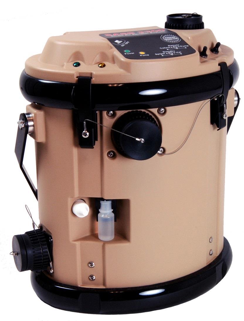
1 Wetted-Wall Air Sampler

2 Front View Features

3 Rear View Features
4 Setting Up the SASS 2300 System

5 Connect Wall Power Transformer Connect System Electrical Power The SASS 2300 requires VDC from either a transformer using mains power or a battery in order to operate. The transformer is connected via the power connector located on the instrument back panel.


.")
6 Connect AC Power Supply OR Install Battery AC Operation Connect the power supply's output plug to the SASS Connect power supply and cord to an AC wall plug. Battery Operation Turn unit upside down. Unscrew the thumbscrews holding the door closed. Open door and insert battery (be sure battery connector and internal mating connector line up). Close the door and tighten thumbscrews.


7 Install Battery Battery power may be used instead of wall power. Three batteries are acceptable for use: 1. Saft BA-5590/U primary battery (or equivalent) 2. Ultralife BA-5390A/U long life primary battery 3. Ultralife UBI-2590 Lithium Ion rechargeable battery.
8 Pre-Start Up Procedure Fill the liquid reservoir with 1000mL to 1200 ml of distilled water. Remove the air exhaust and air inlet covers
9 Switch and LED Locations/Uses Power button Operating Mode switch Green LED. Power On Yellow LED. Pump On Sample Control switch
10 Running in Stand-Alone Mode
 position. Press the Power button.")
11 Turn the SASS On Set the Operating Mode switch to the middle (Remote) position. Press the Power button. Green LED will light.
12 Collecting A Sample: Processing Air To process air, move the Operating Mode switch to the Collect position. To stop processing air, move the Operating Mode switch to the middle (Remote) position. Collect Remote Pump


 position when the")
13 Extracting the Collected Sample (Part 1) To extract a sample, first move the Sample Control switch to either Spigot or Vial position. If Vial is chosen, place a vial in the Filling Station. If Spigot is chosen, connect tubing to the Sample Output Spigot and place a suitable container at the end of the tubing. Leave Sample Control switch in the middle (Standby) position when the unit is not being used. Spigot Standby Vial
14 Extracting the Collected Sample (Part 2) Move the Operating Mode switch to Pump. The yellow LED will light and the sample will be transferred to the selected point. When done, move the Operating Mode switch to the middle (Remote) position. Collect Remote Pump


15 Cleaning the SASS: Automatic Process Prior to cleaning, prepare containers for the flush water. 1 ml of water will be dispensed into the Sample Vial and 20 ml of water will go to the Sample Spigot. To start the process, rapidly toggle the Sample Control switch at least 3 times between any two positions. The cleaning process will be automatically executed.
16 Running from a Computer
17 Running from a Computer The SASS 2300 comes with a Windows program that allows the user to control the SASS 2300 or to change the factory default settings using a computer connected to the instrument via an RS-232 cable. This program is provided on a CD-ROM.


18 Connect Using the RS-232 Cable Connect the female plug to one of the computer s RS-232 communications ports or to a USB port via an RS-232-to-USB adapter Connect the male plug to the back of the SASS 2300.
19 SASS 2300 Control Program Software
20 System Requirements Supported Operating Systems: Windows Server 2003; Windows Server 2008; Windows Vista; Windows XP Processor: 400 MHz Pentium processor or equivalent (Minimum); 1GHz Pentium processor or equivalent (Recommended) RAM:96 MB (Minimum); 256 MB (Recommended) Hard Disk: 1.2 MB of available space CD Drive: Required Display: 800 x 600, 256 colors (Minimum); 1024 x 768 high color, 32-bit (Recommended)

21 Software Installation Insert the CD-ROM in the computer. An installer window should open automatically. Choose Install Software

22 Software Installation When you choose Install Software the installation program should automatically start up. Follow the installation instructions as they appear.

23 Windows 7 and 8 Installation In Windows 7 or 8 systems, a window should open labeled AutoPlay. If this occurs select the Run autorun.exe option. If this does not occur on your system you will need to open the File Explorer window and navigate to the CD drive that holds the install disk. Click on the AutoPlay folder, then on the Docs folder and doubleclick on the setup.exe file. The Welcome to the SASS 2300 Setup Wizard screen shown on the next page should appear.
24 .NET Installation If your computer does not have the.net Framework installed on it yet, instead of seeing the Welcome dialog box you will be prompted to upgrade your operating system by installing the.net Framework. This is necessary for the SASS 2300 Windows program to run. This will require an Internet connection and some time. Unlike the SASS 2300 Windows program, the.net Framework can take several minutes to install depending on the speed of your system and requires up to 500 MB of free hard disk space.

25 Quick Start-Up Guide for Windows Program Place Operating Mode switch in the middle position (Remote). Press the Power button on the lid of the air sampler. The green LED on the lid of the air sampler will light up when the power is turned on.
26 Quick Start-Up Guide for Windows Program Start up the SASS 2300 Windows software program by double-clicking on the Icon on your computer desktop. To start the air sampler, click on the red Fan icon button on the left side of the toolbar in the Windows program. This will change the color of the icon to green and the fan will start running. Before you extract a sample make sure you have chosen either the Spigot or Vial positions using the Sample Destination switch on the lid and have a vial inserted or receptacle attached to the Spigot connection.

27 Quick Start-Up Guide for Windows Program To extract a sample, click the Fan button again on the toolbar in the Windows program to turn the fan off. Then click on the red Pump button on the toolbar to start pumping the sample out. The pump icon will turn green and the yellow LED on the air sampler lid will turn on letting you know that the sample is being pumped out. When you're done pumping the sample out of the unit click on the Pump button again to turn the pump off.
28 Main Software Form Tool Bar Status Text Boxes Status Bar Drop-Down Menus
29 Tool Bar Shortcuts Fan ON/OFF = Same as Operating Mode Switch / Collect Position Pump = Same as Operating Mode Switch / Pump Position Drop-Down Menu Shortcuts
30 Status Text Boxes Counts: displays the signal from the liquid level detector in the air sampler. Ml: displays the number of milliliters of fluid that is circulating in the cyclone. Filling: displays the status of the peristaltic pump that is used to supply makeup water to the cyclone when the fan is running.

31 Status Text Boxes Batt.: displays the battery charge left in the system battery based on the battery voltage. This will either be Full, Med., or Low. C: displays real-time internal electronics temperature. Volts: shows operating voltage. Liters: displays the number of liters of air sampled since the fan was last turned on.
32 Automatic Mode The Automatic Mode form is accessed by choosing Automatic Mode from the Options drop-down menu. is used to program the SASS 2300 so that it will run a predetermined set of steps when the Operations Mode Switch is set to the Collect position.
33 Automatic Mode Enable Automatic mode allows you to create custom recipes which can be saved to a file on the PC, loaded into the SASS 2300, and then run when operating in Automatic Mode. To Enable Automatic Mode click on the Auto Mode button. You can modify any of the parameters in the form by typing new values in the text boxes. Each of these will be discussed more in the slides that follow
34 Automatic Mode Fan Selecting Fan off while pump on will cause the fan to turn off while liquid is being pumped out of the cyclone. This is the recommended default setting. Fan on while pump on the fan will continue to run while the cyclone is being pumped out.
35 Automatic Mode Delay Before Starting First Cycle Entering a non-zero value in the Initial delay time textbox will cause the air sampler to pause for the specified number of seconds before doing anything else. This can be useful if you have stirred up dust in the field and want to allow it to settle after you leave the area before the sampling process starts.
36 Automatic Mode Parameter for Each Cycle In the Parameters For Each Cycle group you can enter the fan, pump, and pause times for each cycle of the auto mode recipe. The Totals group below this contains a Total air sampled text box that allows the user to enter the cumulative air sampled in cubic meters. This group also contains a Number of cycles textbox for entering the desired number of fan/pump/pause cycles.
37 Automatic Mode Cleaning Routine Settings The Cleaning Routine Settings group of controls allows you to run an optional cleaning protocol at the end of each fan / pump / pause cycle. Cleaning initial fill time allows the user to set the amount of time that the cyclone is filled with fluid when the fan starts up. Cleaning fan run time and the Cleaning pump run time allow you to set the fan and pump time for the cleaning routine. The Number of cleaning cycles allows the user to repeat the fan / pump cleaning cycles a number of times. The recommended value is 4
38 Automatic Mode Count Down Timer The Count Down Timer group shows the total run time for the Auto Mode recipe based on the numbers that the user has entered in the textboxes.
39 Automatic Mode Count Down Timer When you click on the Run button these values will be downloaded into the air sampler and the recipe will start to run. As it does, the Count Down Timer will update every second, showing the time remaining until the recipe is complete. In addition to clicking on the Run button, once the instrument has been put in Auto Mode the Auto Mode recipe can also be run by placing the Operating Mode switch in the Collect position. Collect Remote Pump
40 Automatic Mode Count Down Timer If you run an Automatic Mode recipe by clicking on the Run button you must remember to place the unit back into normal mode before disconnecting the air sampler. Otherwise it will remain in automatic mode until it is hooked back up to the PC and changed.
41 Automatic Mode Save To Option You also has the option to save a recipe created using the Automatic Mode form. Click on the Save To PC button on the bottom of the form. A Save As window is opened. Browse to a directory where you want to save the recipe file. Enter a name in the File name textbox at the bottom of the form. The file extension amr (auto mode recipe) will automatically be given to the file name that you specified.
42 Calibration Table The Calibration Table is used to convert raw counts from the optical liquid level detector into milliliters of fluid circulating in the cyclone. This allows the fluid volume in the cyclone tube to be displayed in the real time graph and textboxes. You may view the calibration table by choosing Calibration Table from the Options drop down menu.
43 Calibration Table The Calibration Table cannot be edited by the user in Normal Mode. Each SASS 2300 is individually calibrated at the factory before shipping and should not require re-calibration. However, it is possible to change the calibration table in Expert Mode (Expert Mode is discussed HERE>>).

44 Calibration Table The Scaling Factor at the left bottom of the screen determines the milliliter values shown in the right column in the calibration table. For a SASS 2300 this value must always be set to 7.0. Changing the values in the calibration table can result in poor sampling efficiency or flooding. Only an experienced technician should attempt to re-calibrate a SASS 2300.

45 Demo Mode The Windows software program can be placed in Demo Mode by going to the Options pull down menu and selecting Demo Mode. When the software is in Demo Mode simulated data will be generated which can be useful for training and demonstration purposes. See Operations and Maintenance Manual for more details on using Demo Mode.
46 Expert Mode Entering Expert Mode enables the user to change several operating parameters. Enter Expert Mode by going to the Options pull down menu and selecting Expert Mode. This action will open up the Expert Mode form. Type in the password, Groucho and click on the Enable button (password is case sensitive).
47 Expert Mode Entering Expert Mode enables the user to change several operating parameters including: setting values Reprogram the Microcontroller Refer to the Operations and Maintenance Manual for more details.

48 Filtered This option applies a running average filter to the real-time data from the fluid level detector. To enable choose Filtered from the drop down Options menu on the main screen. A check mark will appear on the left side of the Filtered option indicating that the data is being filtered. Clicking the option again will remove the check mark and the filtering algorithm will be disabled.

49 Sample Pump Timeout The Sample Pump Timeout value can be viewed by selecting it from the Options drop down menu on the main screen. In Expert Mode the Sample Pump Timeout value can be set from 0 to 255 seconds. This is the time that the sample pump will run if turned on using the hardware switch on top of the unit before automatically shutting off. This is done to avoid wearing out the pump and running the battery down if the switch in inadvertently bumped in transit. If the pump is turned on using the Windows software program this parameter will have no effect.

50 Graph Window The Graph window displays the detected liquid volume circulating in the cyclone. The vertical labels on the left side of the graph represent the raw counts from the liquid level detector inside the SASS The vertical labels on the right side of the graph represent the corresponding milliliters of liquid circulating in the cyclone. These values are calculated based on the Calibration Table stored in the air sampler.

51 Log RS-232 Data It is possible to save the RS232 traffic that goes back and forth between the Windows program and air sampler in a text file if desired. Choose the Log RS232 Data option from the Utilities pull down menu. This will open the window shown here. Browse to a directory where you want to save the RS-232 data. Enter a name in the File name textbox at the bottom of the form. The file extension TXT will automatically be given to the file name if you do not specify a file extension. RS232 data files are user editable text files. To stop logging RS232 data simply choose the Log RS232 Data option from the Tools pull down menu again and the check mark will disappear and the data file will be closed.

52 Multiple Sampler Selection If you have multiple air samplers and wish to communicate with more than one air sampler from the same Windows program. This is accomplished by choosing the Multiple Sampler Selection option from the Tools pull down menu.
53 Multiple Sampler Selection This window allows you to select from up to 7 different air samplers. An air sampler is selected by clicking on the button on the left side of the row and assigning a name to it. This name can be changed by typing a new name in the textbox.
54 Multiple Sampler Selection The background color of the Air sampler name, S/N and Connect button are all shown in green, indicating that the air sampler specified on this row is currently connected and communicating with the Windows program.

55 Multiple Sampler Selection If the air sampler is not connected these background colors will be red. When communication has not yet been established, the COM port and PC baud rate drop down menus will become enabled, allowing you to select the desired COM port and baud rate for the air sampler. Once selected you can attempt to connect by clicking on the Connect button.

56 RS-232 Settings The RS-232 Setting window can be opened by going to the Utilities pull-down menu and selecting RS-232 Settings. If you select Auto detect port the program will automatically check each port available on the computer at both of the available baud rates, and 9600 baud. In this mode, the controls in the PC Settings group will be grayed out, but they will still display the port and baud rate that is being tried as all of the different combinations are scanned. If the air sampler is detected at one of these settings it will automatically connect and the text boxes on the main form will start displaying information about the temperature, voltage, etc.

57 RS-232 Settings The Air Sampler Settings group allows you to change the air sampler baud rate. These controls will be grayed out until communication is established with the air sampler. If you change the air sampler baud rate, the PC baud rate will automatically be changed too and the program will then attempt to re-establish communication at the new baud rate. The air sampler baud rate will be saved in non-volatile memory and will be used on subsequent power up.

58 RS-232 Tool Use the RS-232 Tool in the Windows software program if you wish to develop your own software for use with the SASS 2300, or would like to connect the SASS 2300 to another system that is equipped with an RS- 232 port. This tool can be accessed by choosing the RS-232 Tool from the Utilities pull down menu. This will open the window shown.

59 RS-232 Tool The window shown in allows you to monitor all of the RS-232 traffic that is being sent back and forth between the Windows program and the SASS The multi-line Message Sent text box on the left displays messages being sent from the Window software to the SASS The multi-line Message Received text box on the right displays the responses being sent back from the SASS 2300 to the Windows program. Refer to the Operations and Maintenance Manual for a complete listing of all available commands.

60 Run Cleaning Cycle Be sure to connect a waste container to the spigot port on the back of the unit while running the cleaning routine since the cleaning routine will automatically pump fluid out of the spigot port at the end of each cycle.

61 Run Cleaning Cycle The SASS 2300 is capable of running an automated cleaning protocol that will rinse the system out if it has become contaminated for any reason. This can be accomplished in one of two different ways. 1. If the Sample Destination switch is toggled three or more times within three seconds it will cause the automated cleaning protocol to run. 2. The automated cleaning protocol can be run by selecting Run Cleaning Cycle from the Utilities drop down menu which will open up the screen shown.
62 Run Cleaning Cycle If the cleaning routine is initiated by clicking on the Run button the Total Cleaning Time text box in this screen will count down to zero as the protocol runs. Initial fill time is the number of seconds that the pump should fill the cyclone when the fan first powers up. Fan run time is the number of seconds to run the fan.

63 Run Cleaning Cycle At the end of the Fan run time the fan is shut off and the fluid is pumped out the spigot port in the back of the unit for the number of seconds shown in the Pump run time text box. The cycle of running the fan and pump will be repeated until the total number of cycles is equal to the value in the Number of cycles text box. At this point the cyclone will fill for the number of seconds in the Sample vial flush time text box. This fluid is then pumped out of the cyclone and used to flush the sample vial line.

64 Help About Form The SASS 2300 help about form can be accessed by choosing About from the HELP pull down menu. This window displays the version number of the Windows software program as well as the version number for the firmware inside the SASS 2300 microcontroller.
65

66 Battery Installation / Replacement 1. Open the battery door located on the bottom of the instrument by unscrewing the two thumb-screws. 2. Remove the old battery by carefully turning the instrument right-side up and letting gravity do the work. 3. Install the new battery by aligning the battery terminal with the connector at the bottom of the compartment. 4. Slide the battery into the compartment. 5. Close the door and tighten the thumb-screws. 6. Follow applicable local, state and federal regulations in disposing of the used battery.
67 Cleaning the Water Reservoir The water reservoir should be cleaned on a weekly basis to prevent the buildup of bacterial biofilms when the unit is in use. 1. Open the reservoir and invert the instrument to empty any water that may be present. 2. Add a few mls of household bleach and recap the reservoir. 3. Shake the instrument with inversion to make sure the bleach accesses all areas of the reservoir. 4. Open the reservoir, empty the bleach and add a few hundred mls of water. 5. Recap and repeat the shaking and inverting. 6. Empty the water and repeat this process 4 times to make sure all the bleach is gone.

68 Cleaning the Cyclone Tube Cleaning the cyclone tube requires that the instrument be disassembled. That process is described in the following slides. Only a Philips head screwdriver is needed to remove the cyclone tube for cleaning.
69 Cleaning the Cyclone Tube: Step 1 Remove the four (4) screws that secure the front and back latches. Be sure to note which screws also secure the tethers for the exhaust cap and water reservoir cap.

70 Cleaning the Cyclone Tube: Step 2 Release the four (4) latches that secure the top to the unit. Remove Water Fill cap.

71 Cleaning the Cyclone Tube: Step 3 Lift the top of the instrument off and let it hang down over the side of the case. Then disconnect the fan electrical connector. Fan Electrical Connector
72 Cleaning the Cyclone Tube: Step 4 Remove the four (4) screws that attach the exhaust manifold to the case.
 Phillips screws to")
 O-rings that")
73 Cleaning the Cyclone Tube: Step 5 Remove the two (2) Phillips screws to release the inlet manifold. Do not lose the two (2) O-rings that seal the inlet.

74 Cleaning the Cyclone Tube: Step 6 Carefully lift up to remove the fan, cyclone tube and exhaust manifold.


75 Cleaning the Cyclone Tube: Step 7 Disconnect the electrical cable from the fluid level detector then carefully roll the tube off of the outlet spigot. Fluid level detector connection


76 Cleaning the Cyclone Tube: Step 8 Use a twist-and-lift motion to remove the fan unit from the cyclone tube. Be sure to pull straight up to avoid damage to the rotor.


77 Cleaning the Cyclone Tube: Step 9 Use a pipe cleaner to clean the return tube from the top of the cyclone. Unscrew the spigot from the sample outlet and use the pipe cleaner to clean the outlet. A test tube brush works well for cleaning the cyclone itself, if necessary.
78 Disinfecting the Unit The cyclone and internal tubing may be disinfected with household bleach when contaminated with non-pathogenic contamination. Connect the SASS to a computer and start the SASS program. Inject 5 mls of bleach into the air inlet and run the Cleaning Cycle.
79 the SASS 2300 Table 6-1: SASS 2300 Guide ID Symptom Possible Cause Solution or Diagnostic 1 Unit will not turn on; green power indicator off Battery dead 2 Power supply not plugged in or cable disconnected 3 Unit will not turn on; red tilt Unit not level indicator on 4 Fan does not run when the Fan burned out unit switched on 5 Yellow pumping light is Low supply voltage blinking 6 Cyclone interior does not No water in reservoir become wet when fan turned on 7 Fluid in bottom of unit Tube connecting reservoir to cyclone disconnected or leaking Replace battery or substitute with external power. Check cables, substitute with battery power Place on level surface Replace fan Replace battery Fill reservoir Remove top cover to access interior and reconnect or replace. 8 Calibration table corrupted Recalibrate or call Research International 9 Cyclone cup over-fills with Water return tube is blocked Follow cleaning procedure of Chapter 5 water 10 Calibration table corrupted Recalibrate or call Research International 11 Liquid level detector not operating Call Research International 12 Peristaltic pump does not pump sample from cyclone Electrical connection for pump disconnected Remove top cover to access interior and reconnect at PC board 13 fluid in bottom of unit Tubing broken Call Research International 14 fluid in bottom of unit Tubing disconnected from bulkhead fitting Remove backplate and reconnect; dry out 15 Unit does not talk to RS-232 cable not seated properly in Reconnect outboard computer bulkhead fitting 16 COM port on computer not functioning See your computer manual

80 Upgrading the Firmware If it is necessary to upgrade the firmware in the SASS 2300 first connect the unit to a computer using the RS-232 port and start up the Windows software program as described in Running from a computer section Select Expert Mode from the Options pull down menu and type in the password Groucho. Note this is case sensitive. This will put the software in expert mode.
81 Upgrading the Firmware You should now see a new option listed under the Utilities pull down menu entitled Reprogram Microcontroller. Select this option and the window shown below will open up. Use this window to locate the directory where the new firmware is stored. New versions of the firmware will always have the file extension.s19. Locate the new firmware that you wish to install doubleclick on the filename, or click on the filename once and then click on the Open button.
82 Upgrading the Firmware A progress bar window like the one shown below will open showing the progress as the firmware in the SASS 2300 is reprogrammed. This process takes about 10 to 30 seconds, depending on the baud rate setting.


83 Upgrading the Firmware When the reprogramming process is complete the reprogramming status bar will automatically close and the microcontroller will reboot and proceed to run with the new firmware. Extreme care should be exercised to not bump the cable or shut off the instrument while reprogramming the firmware. If the process is interrupted it will not be possible to recover without shipping the unit back to the factory.
84 For More Information Contact: Research International, Inc Beaton Road SE Monroe, WA USA Phone: Toll Free: Web: Technical Support
Navigation for. Using the SASS 3100 Dry Air Sampler
 - Introduction: SASS 3100 Shipping Package (U.S.) - SASS 3100 Recommended Options - SASS 3100 Filter Media - The SASS 3100 uses a disposable filter cartridge that simply snaps onto the instrument. Each
FROG-4000TM Quick Start Guide
 FROG-4000TM Quick Start Guide 1 Precautions DO NOT invert the instrument with the sparge bottle attached. DO NOT transport or store the instrument with liquid in the sparge bottle. DO NOT handle or carry
Agilent ICP-OES SVS 2 Productivity Package Installation and Upgrade Instructions
 Agilent ICP-OES SVS 2 Productivity Package Installation and Upgrade Instructions NOTICE: This document contains references to Varian. Please note that Varian, Inc. is now part of Agilent Technologies.
USB INTERFACE SYSTEM DIG-703A / DIG-703B PRODUCT MANUAL. DOC-114 Rev 1.7. Copyright 2013 All Rights Reserved
 instrumentation and software for research USB INTERFACE SYSTEM DIG-703A / DIG-703B PRODUCT MANUAL DOC-114 Rev 1.7 Copyright 2013 All Rights Reserved Med Associates, Inc. P.O. Box 319 St. Albans, Vermont
Section. Service & Maintenance. - Core & Hard Disk Drive (HDD) - Amplifier - Monitor - UPS - Dollar Bill Acceptor - Fan Filter G - 1
 - Amplifier - Monitor - UPS - Dollar Bill Acceptor - Fan Filter G - 1") Section G Service & Maintenance - Core & Hard Disk Drive (HDD) - Amplifier - Monitor - UPS - Dollar Bill Acceptor - Fan Filter G - 1 Core Removal Core & HDD 1. Open the door. 2. Perform shutdown procedure.
Section G Service & Maintenance - Core & Hard Disk Drive (HDD) - Amplifier - Monitor - UPS - Dollar Bill Acceptor - Fan Filter G - 1 Core Removal Core & HDD 1. Open the door. 2. Perform shutdown procedure.
6-Series Sonde Quick Start Guide
 6-Series Sonde Quick Start Guide This document will assist an experienced user with the steps required to make your YSI 6-Series product operational. For full instructions, please refer to the 6-Series
Installing TAM Air Assistant Software TM
 Installing TAM Air Assistant Software TM Installation Instructions This document describes how to make a new installation of TAM Air Assistant. TAM Air Assistant is intended to be installed on a PC running
Remote Deposit Service
 Remote Deposit Service Start Up Guide *Screen shots are shown for illustrative purposes only and may vary based on the version of Windows you are currently using. Step 1: Confirm your PC meets system
FX Tools Software Package - FX CommPro N2 User s Guide
 User s Guide FX CommPro N2 Issue Date September 25, 2008 FX Tools Software Package - FX CommPro N2 User s Guide FX Tools Software Package FX CommPro N2... 3 Introduction...3 Installation... 4 Installing
ibidi PumpControl Instruction Manual Version 1.5.0
 ibidi PumpControl Instruction Manual Version 1.5.0 II ibidi GmbH 2011, version 1.5.0, revision 2, 2011-10-26, Andreas Rainer Table of contents 1 General Information... 1 1.1 System Requirements... 1 1.2
PL200M. 200Mbps powerline adapter. User Manual
 PL200M 200Mbps powerline adapter User Manual Content 1 Introduction... 130 1.1 System Requirements... 130 1.2 Packing List... 130 2 Safety Precautions... 131 3 Getting to Know the Adapter... 132 3.1 Ethernet
Manual for MantraJet 1100 CD/DVD auto-printer
 Manual for MantraJet 1100 CD/DVD auto-printer Rev 1.03 September 7, 2010 Table of contents Specifications...3 Unpacking MantraJet 1100...4 Quick installation reference MantraJet 1100...7 Installation of
MantraJet 1100 CD/DVD autoprinter Operator s manual
 MantraJet 1100 CD/DVD autoprinter Operator s manual Rev 1.00 May 7, 2008 Table of contents 1. Specifications.. Page 2 2. Unpacking you MantraJet 1100 Page 3 3. Using your autoprinter for the first time.
FlowAccess TM GETTING STARTED. Windows software for Skalar SAN plus systems. Version and up
 FlowAccess TM V3 Windows software for Skalar SAN plus systems Version 3.1.0.4 and up GETTING STARTED FlowAccess TM V3 Windows software for Skalar SAN plus systems Version 3.1.0.4 and up Getting started
EXPRESS. Users Guide. Version 3.5
 EXPRESS Users Guide Version 3.5 Table of Contents 1 System Overview... 3 2 System Requirements... 3 3 Contents in ECMTUNE System Box... 3 4 Installation Information... 4 5 Registration Information... 7
Power. Document Part Number: This guide explains how the computer uses power. December 2005
 Power Document Part Number: 393525-002 December 2005 This guide explains how the computer uses power. Contents 1 Power controls and lights 2 Power sources Connecting the AC adapter.......................
XEScan Solution Installation Guide 701P38349 April 2002
 XEScan Solution Installation Guide 701P38349 April 2002 Trademark Acknowledgments Windows 98, Windows ME, Windows NT 4.0, Windows 2000, and Internet Explorer are registered trademarks of Microsoft Corporation.
ARA FTS Flow Calibrator. Operation Manual August 1, 2016
 ARA FTS Flow Calibrator Operation Manual August 1, 2016 TABLE OF CONTENTS SECTION PAGE 1. INTRODUCTION 1 2. GETTING STARTED 1 2.1. Navigation 1 2.2. Charge Battery 1 2.3. Set Date and Time 2 2.4. Plug-In
USER GUIDE Turbidity Meter Model TB400
 99 Washington Street Melrose, MA 02176 Phone 781-665-1400 Toll Free 1-800-517-8431 USER GUIDE Turbidity Meter Model TB400 Visit us at www.testequipmentdepot.com Introduction Congratulations on your purchase
3-Axis G-Force Datalogger
 User's Guide 3-Axis G-Force Datalogger Model VB300 Introduction Congratulations on your purchase of the VB300 G-Force Datalogger. The Model VB300 can measure and record shock and vibration (acceleration)
ULTRASONIC VOCALIZATION DETECTOR TEST PACKAGE
 ULTRASONIC VOCALIZATION DETECTOR TEST PACKAGE USER S MANUAL ANL-939 User s Manual DOC-161 Rev. 1.3 Copyright 2007 All Rights Reserved MED Associates, Inc. P.O. Box 319 St. Albans, Vermont 05478 www.med-associates.com
Removal and Installation8
 8 Screw Types 8-4 Top Cover Assembly 8-5 Left Hand Cover 8-6 Right Hand Cover 8-10 Front Panel Assembly 8-14 Left Rear Cover 8-15 Right Rear Cover 8-16 Extension Cover (60" Model only) 8-17 Media Lever
USB-Link Technical Guide
 www.wattmaster.com USB-Link Technical Guide USB-Link Code: SS0070 Table of Contents General Information... 3 USB-Link Overview...3 System Requirements...3 Quick Guide... 4 Connection and Wiring... 5 USB-Link
Installation. Installation 1
 Installation 1 Installation The SP35 printer is easy to install and use. It is also flexible; you can connect and use it in many different ways. Most often, one printer is connected to one PC. However,
CncGcoder Models HD & HDx Manual
 CncGcoder Models HD & HDx Manual Table of Contents WELCOME... 3 IN THE BOX... 4 Optional Accessories...4 HANDHELD OVERVIEW... 5 Overview...5 Charging the Battery...6 Turning On and Off...6 Plugging in
Copyright 2007 Hewlett-Packard Development Company, L.P. Windows is a U.S. registered trademark of Microsoft Corporation.
 Drives User Guide Copyright 2007 Hewlett-Packard Development Company, L.P. Windows is a U.S. registered trademark of Microsoft Corporation. The information contained herein is subject to change without
Operating & Maintaining the Connex500/350 3-D Printer
 Operating & Maintaining the Connex500/350 3-D Printer Starting the Connex Printer... 2 Loading Model and Support Cartridges... 4 Producing Models... 5 Printer Interface Color Key... 7 Printing Indicators...
USER MANUAL Video Particle Counter with built in Camera Model VPC300
 USER MANUAL Video Particle Counter with built in Camera Model VPC300 Additional User Manual Translations available at www.extech.com Introduction Thank you for selecting the Extech Instruments Model VPC300
Copyright 2007 Hewlett-Packard Development Company, L.P.
 Drives User Guide Copyright 2007 Hewlett-Packard Development Company, L.P. The information contained herein is subject to change without notice. The only warranties for HP products and services are set
Wireless transfer of screening data from ALGO 3i Screener to PC
 Wireless transfer of screening data from ALGO 3i Screener to PC This technical notice provides information on transmitting screening results from your ALGO 3i Newborn Hearing Screener to a personal computer
FluoroSELECT Fluorometer User s Manual
 FluoroSELECT Fluorometer User s Manual Version 4.4.A Sigma-Aldrich Chemie GmbH Industriestrasse 25 CH-9470 Buchs Switzerland EurTechServ@sial.com techservice@sial.com (US and Canada) sigma-aldrich.com
DIGITAL ENHANCED CORDLESS TELEPHONE with Caller ID Function CL-3350 INF USER' S MANUAL
 DIGITAL ENHANCED CORDLESS TELEPHONE with Caller ID Function CL-3350 INF USER' S MANUAL Congratulations on purchasing our high quality product. Please read the manual carefully to find out all features
InVue BT128 Refractometer
 ADVANCED MATERIALS HANDLING USER GUIDE InVue BT128 Refractometer Process monitoring for laboratory fluid applications in a benchtop package TABLE OF CONTENTS Cautions and Warnings... 4 Safe Disposal...
INSPECTION TOOL. Wireless Inspection Camera with Recordable Monitor. EU Environmental Protection. Model: 8802AL, 8803AL. Model: 8802AL, 8803AL
 TM TM INSPECTION TOOL Wireless Inspection Camera with Recordable Monitor Model: 8802AL, 8803AL EU Environmental Protection Waste electrical products should not be disposed of with household waste. Please
Super Parameter Programmer SPP-01
 Super Parameter Programmer SPP-01 Dear user: Thank you very much for selecting our product! This manual offers important information and suggestions about use and troubleshooting, etc. Please read this
Dolphin ebase. Communication Cradle for the Dolphin 9700 Mobile Computer. User s Guide
 Dolphin ebase Communication Cradle for the Dolphin 9700 Mobile Computer User s Guide Introduction The Ethernet Base (ebase) enables a single Dolphin 9700 computer to communicate with a host device over
HDT-318 Thermo-Hygrometer with Data Logger. (Air Humidity/Temperature) Instruction Manual
 Instruction Manual") HDT-318 Thermo-Hygrometer with Data Logger (Air Humidity/Temperature) Instruction Manual CONTENTS 1. SAFETY INFORMATION... 2 2. GENERAL DESCRIPTION... 2 3. FEATURES... 2 4. SPECIFICATIONS... 3 5. SYMBOL
HDT-318 Thermo-Hygrometer with Data Logger (Air Humidity/Temperature) Instruction Manual CONTENTS 1. SAFETY INFORMATION... 2 2. GENERAL DESCRIPTION... 2 3. FEATURES... 2 4. SPECIFICATIONS... 3 5. SYMBOL
Phone Setup. Phone Hardware Installation. Install the Phone Battery. Phone Hardware Installation, on page 1 Phone Configuration Tasks, on page 15
 Phone Hardware Installation, on page 1 Phone Configuration Tasks, on page 15 Phone Hardware Installation Install the Phone Battery Before you can use your phone, you must install and charge the battery.
QUICK-START GUIDE. Quick Start Guide Temperature Controlled QCM Cell WHAT DOES GAMRY SOFTWARE DO?
 www.gamry.com 1-215-682-9330 techsupport@gamry.com We have a variety of resources available to help you get started. Feel free to visit our website to find out more information on: Application Notes -
USER GUIDE. Video Particle Counter with built in Camera. Model VPC300
 USER GUIDE Video Particle Counter with built in Camera Model VPC300 Introduction Thank you for selecting the Extech Instruments Model VPC300 Particle Counter with Camera. The VPC300 has a Color TFT LCD
Universal USB 2.0 Docking Station. User s Manual
 Universal USB 2.0 Docking Station User s Manual 2012. All Rights Reserved. Universal USB 2.0 Docking Station User s Manual This revision: 07/2012 Model number: Serial number: Date of purchase: Place of
Dome C3i Digital Flat-Panel Display Dome DX2/PCI Display Controller Dome CXtra Software QUICK REFERENCE. Windows XP Windows 2000
 America Sales Planar Systems, Inc. 1195 NW Compton Drive Beaverton, OR 97006-1992 USA phone + 1 (503) 748-1100 fax + 1 (503) 748-1493 Medical Sales Planar Systems, Inc. 400 Fifth Avenue Waltham, MA 02451-8738
2.2. Facilities Requirements
 2.2. Facilities Requirements Facilities requirements for the alpha-se system are listed in Table 2-1 and the system dimensions are given in Figure 2-1. As shown in Figure 2-2, the preferred clear work
Power. Document Part Number: This guide explains how the computer uses power. March 2006
 Power Document Part Number: 396855-001 March 2006 This guide explains how the computer uses power. Contents 1 Power control and light locations 2 Power sources Connecting the AC adapter....................
M950 Thermometer Instructions Connectors: Probe Connector Please Attach Probe Temperature Probe Error Please Try Another Probe
 M950 Thermometer Instructions GLA Agricultural Electronics 3563 Sueldo Street, Suite D San Luis Obispo CA 93401-7331 800.346.1182/ 805.541.3758 / info@gla-ag.com Connectors: Probe Connector Attach Probe
READ ME FIRST Windows 98/ME/2000
 READ ME FIRST Windows 98/ME/2000 *DSL Equipment Installation Guide: Alcatel Speed Touch PC *Digital Subscriber Line Part Number: AlcatelPC9x02A Version 1.2-A Table of Contents Follow Steps 1 through 7
8380 RPC Return Path Combiner. User s Guide
 8380 RPC Return Path Combiner User s Guide Notice Every effort was made to ensure that the information in this manual was accurate at the time of printing. However, information is subject to change without
USB-Link 2 Technical Guide
 www.wattmaster.com USB-Link 2 USB-Link 2 Code: SS0073 Version 4.11 and up Table of Contents General Information... 3 USB-Link 2 Overview...3 System Requirements...3 Quick Guide... 4 USB-Link 2 Driver Installation
PROFESSIONAL. Users Guide. Version 3.5
 PROFESSIONAL Users Guide Version 3.5 Table of Contents 1 System Overview... 3 2 System Requirements... 3 3 Contents in ECMTUNE System Box... 3 4 Installation Information... 4 5 Registration Information...
User Guide. ExStik FL700. Fluoride Meter
 User Guide ExStik FL700 Fluoride Meter Introduction The model FL700 is a system specifically designed for the quick and accurate measurement of fluoride ions in drinking water and other aqueous samples.
Upgrading Einstein Using the Einstein 1.5 Upgrade Kit. An EAB board with Production Einstein 1.5 Software EEPROM Chips.
 TECHNICAL BULLETIN Upgrading Einstein Using the Einstein 1.5 Upgrade Kit This bulletin explains how to use the components of the CPC Upgrade Kit to upgrade a pre-1.5 version Einstein unit to the latest
Flow Control. User s Guide. Programmable Dosing Pumps for Liquid Delivery, Solutions Application & Switching
 Flow Control User s Guide Programmable Dosing Pumps for Liquid Delivery, Solutions Application & Switching From Single Unit to Multi-Channel Systems Manual and Software controls for Automated Operation
Dionex AS-AP Sample Conductivity and ph Accessory Setup and Operation Guide
 Dionex AS-AP Sample Conductivity and ph Accessory Setup and Operation Guide Document No. 065470 Revision 02 February 2012 2012 by Thermo Fisher Scientific Inc. All rights reserved. Chromeleon is a registered
Sound Card Installation for Windows 95/98
 Sound Card Installation for Windows 95/98 Hardware Installation 1. Shut down Windows and power down system. Unplug power cable from the system. 2. Remove screws and open system enclosure. 3. Remove static
SensorWATCH Basic RH - Wireless Setup Users Help Guide Part Number: A Revision: 1.1.0
 SensorWATCH Basic RH - Wireless Setup Users Help Guide Part Number: A53-7974-13-001 Revision: 1.1.0 Page 1 SensorWATCH Basic RH - Wireless SetupUsers Help Guide 1.1.0 Table of Contents 1.0 - Quick Setup
EL7060 Series SERVICE MANUAL
 EL7060 Series SERVICE MANUAL 1 TABLE OF CONTENTS 1 General description... 4 1.1 Exploded view... 5 2 ACCESSIBILITY... 5 2.1 Dust Bag Cover.. 7 2.2 Display Cover.8 2.3 PCB Display/Switch..9 2.4 Top Cover..10
AstroJet L1 Quick Start Guide
 AstroJet L1 Quick Start Guide Step 1 Remove Printer and Accessories from packaging Place Printer on a level, stable surface. Make sure Printer is level. Step 2 Install Ink Drip Tray Assembly 1. Open Ink
USER GUIDE. Video Particle Counter with built in Camera. Model VPC300
 USER GUIDE Video Particle Counter with built in Camera Model VPC300 Introduction Thank you for selecting the Extech Instruments Model VPC300 Particle Counter with Camera. The VPC300 has a Color TFT LCD
AstroJet S1 Quick Start Guide
 AstroJet S1 Quick Start Guide Step 1 Remove Printer and Accessories from packaging Place Printer on a level, stable surface. Make sure Printer is level. Step 2 Assemble Ink Drip Tray Assembly 1. Select
Register your product and get support at. AS111. User manual
 Register your product and get support at www.philips.com/welcome AS111 User manual Contents 1 Important 3 Safety 3 Notice 3 English 2 Your docking speaker for Android 5 Introduction 5 What's in the box
Copyright 2008 Hewlett-Packard Development Company, L.P. Microsoft and Windows are U.S. registered trademarks of Microsoft Corporation.
 Drives User Guide Copyright 2008 Hewlett-Packard Development Company, L.P. Microsoft and Windows are U.S. registered trademarks of Microsoft Corporation. The information contained herein is subject to
Version 4.1 Software Installation Guide (Full)
") Version 4.1 Software Installation Guide (Full) Important! Read First You must have administrative rights to install the E-A-Rfit software and the drivers for the hardware (speaker). Ensure your PC meets
Version 4.1 Software Installation Guide (Full) Important! Read First You must have administrative rights to install the E-A-Rfit software and the drivers for the hardware (speaker). Ensure your PC meets
Copyright 2007 Hewlett-Packard Development Company, L.P.
 Drives User Guide Copyright 2007 Hewlett-Packard Development Company, L.P. The information contained herein is subject to change without notice. The only warranties for HP products and services are set
Managing Individual Components
 CHAPTER 3 This chapter describes how to install the Field Replaceable Units (FRUs) in the Cisco SFS 7008P system. About the Field Replaceable Units The following Field Replaceable Units (FRUs) are a part
Magnetic Immunoassay Reader Operator Manual
 Page 1 of 8 Magnetic Immunoassay Reader Operator Manual Table of contents 1 Introduction...1 2 Magnetic Immunoassay Reader...1 2.1 Contact information and spare parts...1 3 Contents of delivery...1 4 Technical
Installing the Printer Software
 4 Printing Your First Page Attaching the Paper Support 7 1 Checking the Printer 6 2 Plugging in the Printer 3 Installing the Ink Cartridges 5 Installing the Printer Software Connecting the Printer 4012581-00
Quick start guide. Install Connect Transfer Enjoy. Philips GoGear audio player
 Philips GoGear audio player SA2610 SA2611 SA2615 SA2616 SA2620 SA2621 SA2625 SA2626 SA2640 SA2641 SA2645 SA2646 Quick start guide 1 2 3 4 Install Connect Transfer Enjoy Need help? Please visit www.philips.com/welcome
DT800 Lane Timer Manual
 DT800 Lane Timer Manual Features: 1) 8000 Memories 2) Built-in PRINTER 3) Up to10 Lane Buttons 4) PC Upload Function 5) 12/ 24Hr User-selectable Clock 6) 4-Digit Bib Number 7) 4-Digit Place Counter 8)
Part # Quick-Start Guide. SpeedStream 4200 Modem PPPoE Modem Router
 Part # 007-0-00 Quick-Start Guide SpeedStream 00 Modem PPPoE Modem Router Before you begin, Verify that the following items came with your DSL kit: Step > Install Line Filters 7 SpeedStream Device Documentation
Instructions for Installing FlashUpdate and Downloading Updates for Super Buddy Satellite Meter
 Instructions for Installing FlashUpdate and Downloading Updates for Super Buddy Satellite Meter Updates to the Field Guide and to the instrument firmware are available from the Applied Instruments website.
BESTCOMSPlus Software
 9440300990 Rev P 123 General Description BESTCOMSPlus is a Windows -based, PC application that provides a user-friendly, graphical user interface (GUI) for use with Basler Electric communicating products.
AirPro Surveyor 2 Manual
 AirPro Surveyor 2 Manual AirPro Surveyor Specifications Table of Contents Size 3/8 x 7 1/2 x 4 3/8 Weight 4.6 lbs. 2094 g Dynamic Range 1-1000 ml/min. total flow/constant flow Flow Capacity (8 Hrs.) 1000
Humidity & Temperature Datalogger
 User Manual Humidity & Temperature Datalogger Model RHT Additional User Manual Translations available at www.extech.com Introduction Congratulations on your purchase of this Temperature and Humidity datalogger.
Phone Setup. Phone Hardware Installation. Install the Phone Battery. Phone Hardware Installation, page 1 Phone Configuration Tasks, page 11
 Phone Hardware Installation, page 1 Phone Configuration Tasks, page 11 Phone Hardware Installation Before you can use your phone, you must install and charge the battery. The battery may already be installed
Quick Start Guide. Quick Start Guide I
 Quick Start Guide Quick Start Guide I II Quick Start Guide Contents of Package The Multi-Converter package contains the following items: > One (1) Multi-Converter Device > One (1) USB Cable > One (1) Installation
Instructions for Use
 Multilingual version 3.4 Lite version is intended for patient use only; Some physician features are disabled. Instructions for Use Table of Contents 1 Introduction... 1 2 Installing and Starting Software...
Rev 1 3/19/2010 Initial Release Rev 2 5/13/2010 Removed TouchReader+ information from installation instructions.
 Revisions Rev No. Date Description Rev 1 3/19/2010 Initial Release Rev 2 5/13/2010 Removed TouchReader+ information from installation instructions. This document contains proprietary information. It is
CryoFocus-4 GC Cryogenic Trap
 CryoFocus-4 GC Cryogenic Trap Installation Guide CryoFocus-4 onto Shimadzu GC-2010 www.atasgl.com Disclaimer ATAS GL International B.V. makes no representations or warranties with respect to the contents
Operation Manual. snapshot. cuvettes. Pi-102 Luminometer
 Operation Manual Pi-102 Luminometer snapshot cuvettes Version: 2.0 Hygiena International Ltd. January 2013 Contents Page 1. The instrument 3 1.1 Instrument details 1.2 Cuvette size to be used 1.3 Explanation
MC-12 Software Installation Instructions
 MC-12 DOCUMENTATION CONVENTIONS This document contains software installation instructions for the MC-12/MC-12 Balanced. Refer to the MC-12 User Guide for general safety, installation, and operating instructions.
8 Button RS232/IR. Control Panel. MuxLab Inc A / SE A
 8 Button RS232/IR Control Panel 500816 MuxLab Inc. 2016 94-000833-A / SE-000833-A SAFETY PRECAUTIONS To insure the best use from the product, please read all instructions carefully before using the device.
Alternative B Type Mid-Span Power Sourcing Equipment. User s Guide
 Alternative B Type Mid-Span Power Sourcing Equipment User s Guide REGULATORY STATEMENTS FCC Certifications This equipment has been tested and found to comply with the limits for a Class B digital device,
1. Purchasing new ink cartridges: 2. Replace the battery of the digital pen when any of the followings occurs:
 Users Manual Welcome Dear user, thanks for purchasing this product. Much investment in time and effort has gone into its development, and it is our hope that it will give you many years of trouble-free
Universal USB 3.0 Docking Station. User s Manual
 Universal USB 3.0 Docking Station User s Manual 2012. All Rights Reserved. Universal USB 3.0 Docking Station User s Manual Original Issue: 07/2012 Model number: Serial number: Date of purchase: Place of
Phantom Quick Start User Guide Vision Research - AMETEK Material Analysis Division
 Phantom Quick Start User Guide Software Revision: 2.7.756.2 Updated: Wednesday, January 27, 2016 Contents 3 Table of Contents Foreword 0 Part I Quick Start Guides 6 1 Phantom v-series Cameras via Phantom
Checklist for the SMPS & CPC (5.400 & 5.500) PART 1 Setup of the external Plumbing (for the DMA and the CPC):
 PART 1 Setup of the external Plumbing (for the DMA and the CPC):") Checklist for the SMPS & CPC (5.400 & 5.500) PART 1 Setup of the external Plumbing (for the DMA and the CPC): Checklist uses laptop as an external control device (ACER, aspire 1400) and the long DMA (Vienna-type
Checklist for the SMPS & CPC (5.400 & 5.500) PART 1 Setup of the external Plumbing (for the DMA and the CPC): Checklist uses laptop as an external control device (ACER, aspire 1400) and the long DMA (Vienna-type
Humidity + Temperature + Pressure Datalogger
 User's Guide Humidity + Temperature + Pressure Datalogger Model RHT50 Introduction Congratulations on your purchase of the Relative Humidity / Temperature / Pressure Datalogger. This datalogger can measure
Table of Contents. 1 Welcome. 2 Install your Access Point-I. 3 Using the Access Point-I
 Table of Contents 1 Welcome Introducing the Avaya Wireless LAN 1-1 About the Access Point-I 1-2 Finding Information 1-3 2 Install your Access Point-I Overview 2-1 Verify Kit Contents 2-2 Write Down Product
Installation and Operation Back-UPS BR1000G-IN / BR1500G-IN
 Installation and Operation Back-UPS BR1000G-IN / BR1500G-IN Important Safety Information Read the instructions carefully to become familiar with the equipment before trying to install, operate, service
12/2013. Installation Guide & User Manual
 12/2013 Installation Guide & User Manual ABOUT THIS MANUAL This manual has been written to help you understand all the functions and capabilities of the Yamaha Snowmobile Diagnostic Tool in order to gain
CBT LW 4-PUMP ADD-ON INTERNATIONAL INSTALLATION GUIDE
 CBT LW 4-PUMP ADD-ON INTERNATIONAL INSTALLATION GUIDE 2 General information This manual contains technical information regarding Bayer SeedGrowth Equipment. Please read and understand these instructions
Graphical User Interface V1.0.3
 Graphical User Interface V1.0.3 Application User Guide 2015 MCI Solutions. All rights reserved. 240815-01 www.mcisolutions.ca Page ii Getting Started Table Of Contents Introduction.................................................
Adding or Replacing a PCI Card
 Caution There are static-sensitive electronics inside the unit. Before you handle any parts, make sure you are working at a static-controlled workstation and that you are properly grounded. Three PCI cards
6165 MONEY COUNTING SCALE
 MANUAL English Nederlands Deutsch Français Español Italiano Português Polski Česky Slovenčina Magyar България 6165 MONEY COUNTING SCALE TABLE OF CONTENTS 01. INTRODUCTION page 3 1.1 Product 1.2 Display
TDS/SALT/TEMP TRACERTM POCKETESTER CODE 1749-KIT. Pool Professional s Meter
 TDS/SALT/TEMP TRACERTM POCKETESTER CODE 1749-KIT Pool Professional s Meter TRACER EC/TDS/SAL POCKETESTER TM CODE 1749-KIT TABLE OF CONTENTS Introduction... 4 Specifications... 4 Contents... 5 Parts &
Firmware, Database, & PC Application Update Installation Instructions
 Firmware, Database, & PC Application Update Installation Instructions IMPORTANT Please read before you begin the installation. To avoid possible errors, it is recommended to install the updates as described
User manual. BookDrive. Automatic Page-turning Scanner
 User manual BookDrive Automatic Page-turning Scanner BookDrive User s Guide All rights reserved. 2005 Atiz Innovation Co., Ltd. Under the copyright laws, this manual may not be copied, in whole or in part,
Chapter 2: Disassembly
 P370EM / P370EM3 Chapter 2: Overview This chapter provides step-by-step instructions for disassembling the P370EM / P370EM3 series notebook s parts and subsystems. When it comes to reassembly, reverse
AD Leak Tester INSTRUCTION MANUAL 1WMPD
 AD-1690 Leak Tester INSTRUCTION MANUAL 1WMPD4002043 2009 A&D Company Ltd. All rights reserved. No part of this publication may be reproduced, transmitted, transcribed, or translated into any language in
READ ME FIRST Windows 95/98/Me/2000
 READ ME FIRST Windows 95/98/Me/2000 *DSL Equipment Installation Guide: Efficient Networks 5260 *Digital Subscriber Line Part Number: 52609x02 Version 1.2-A Table of Contents Follow Steps 1 through 8 to