Digital Display Wall Application Management Software
|
|
|
- Sheryl Farmer
- 5 years ago
- Views:
Transcription

1 VWAS6.0 日常使用手册 Digital Display Wall Application Management Software VWAS6.0/VCMS/VEMS User Manual
2 Copyright Statement This manual is the copyright property of VTRON. Without prior written approval from VTRON, any part of this manual shall not be duplicated or distributed in any way or by any means. This manual is subject to change due to technical upgrading without prior notice. VTRON is the registered trademark of VTRON. Windows and Windows XP are the trademarks or registered trademarks of Microsoft in USA and/or other countries (regions).other product names and company names mentioned in this document may be the trademarks of their respective owners. This manual is an introduction to the digital display wall application software developed by VTRON. In actual use, the actual software interface in this manual may be different depending on the hardware resources used or the operation habit of the user.
3 CHAPTER I INTRODUCTION TO VWAS USER INTERFACE DEFAULT INTERFACE MAIN MENU AND TOOLBAR Main function zone (toolbar): Function configuration zone Virtual display zone The hidden main menu RIGHT-KEY MENU OPERATIONS CUSTOM INTERFACE Main interface Interface customization Desktop customization tool CHAPTER 2 HARDWARE DEVICE MANAGEMENT SIGNAL SOURCE Adding signal source Modifying signal source Deleting signal source Menu operations for signal sources MATRIX Adding matrix Modifying matrix Deleting matrix DISPLAY WALL Adding display wall Modifying display wall Deleting display wall Menu operations of the virtual display wall Multifunctional Layout and Display Wall OTHER DEVICES DVS Multifunctional device Layout of multifunctional devices Multifunction preview Image splitter Preview server CHAPTER 3 CENTRALIZED CHANNEL CONFIGURATION MATRIX CONFIGURATION OTHER DEVICE CONFIGURATION DISPLAY WALL CONFIGURATION http : // 3
4 CHAPTER 4 MODE AND WORKFLOW MODE MANAGEMENT Mode editing Adding a mode Modifying a mode Deleting a mode Executing a mode Mode preview Mode hotkey definition WORKFLOW MANAGEMENT Adding scheme Modifying a workflow Deleting workflow Executing workflow Workflow hotkey definition CHAPTER 5 OPERATIONS ON SIGNAL WINDOWS DIFFERENCE BETWEEN WINDOWS FOR OPTICAL ENGINES AND WINDOWS FOR PROCESSORS TO OPEN WINDOW ON DISPLAY WALL Opening windows for optical engines Opening processor window Opening VLINK window Opening multiple windows MENU FOR WINDOWS General operations for windows Window style Window property Window signal path Signal polling PTZ control CHAPTER 6 SIGNAL PREVIEW AND DISPLAY WALL SHARING PREVIEW SERVER SIGNAL PREVIEW DISPLAY WALL SHARING CHAPTER 7 STATUS INFORMATION RUNTIME INFORMATION ALARM INFORMATION Searching for alarm information Clearing alarm information Exporting alarm information USER LOGS http : // 4
5 7.3.1 Recording daily operations Log inquiry Clearing log Exporting log ALARM MONITORING CHAPTER 8 OTHER SYSTEM SETTINGS AND CUSTOM APPLICATIONS STARTING THE SERVICE PANEL SYSTEM OPTIONS System configuration Stylized grids for display wall Workflow hotkey setting Mode hotkey setting USER MANAGEMENT User management functions Adding users Modifying users Deleting users IMPORTING RESOURCES RESOURCE BACKUP AND RESTORE MULTI-MOUSE OPERATIONS Execution Connection MOVING CAPTION POWERIMAGE OTHER FUNCTIONS Method for mapping configuration: Method for mapping cancellation: Method for mapping modification: CHAPTER 10 LCD DISPLAY WALL CONFIGURATION MANAGEMENT CONFIGURATION INTERFACE ON/OFF MANAGEMENT LCD PARAMETER ADJUSTMENT (FACTORY CONFIGURATION) LCD STATUS QUERY OSD MENU SETTING SYSTEM PARAMETER CONFIGURATION CHAPTER 11 LED DISPLAY WALL CONFIGURATION MANAGEMENT CONFIGURATION INTERFACE HARDWARE DEVICE MANAGEMENT LED controller management Multifunction processor management http : // 5
6 11.3 DISPLAY WALL CONFIGURATION Adding display wall Saving display wall Deleting display wall LED CONTROLLER CONFIGURATION Setting LED controller properties Setting input properties Setting output properties Test pattern configuration Setting LED controller display properties Setting LED controller system properties Setting Version information Setting master/salve output position RECEIVER BOARD CONFIGURATION Receiver board properties Color temperature and brightness Gamma curve configuration Test pattern configuration of the receiver board Scanning property configuration Other properties configuration Display mode management MULTIFUNCTION PROCESSOR CONFIGURATION Configuring multifunction processor properties Configuring the multifunction processor timer Configuring the multifunction processor switch Configuring the multifunction processor system CHAPTER 12 LCD/LED OPERATING TERMINAL LOGIN MAIN MENU OPERATIONS Alarm information Matrix switching About Logout Exit Minimize and close MODE AND WORKFLOW Mode list Workflow list OPERATIONS OF THE VIRTUAL WALL Virtual wall switching http : // 6
7 Virtual wall Toolbar of the virtual wall window Turning display wall ON/OFF SIGNAL SOURCE LIST FUNCTION CONTROL SYSTEM MANAGEMENT UPDATE MANAGEMENT CHAPTER 14 FAQ AND TROUBLESHOOTING Preview mode List mode Signal query Opening window Replacing window Moving window Zooming window ALARM AND LOGIN STATUS BAR CHAPTER 13 WEB CLIENT INTERFACE STATUS MONITORING Engine status Processor status User operation log Device alarm log Device event log http : // 7
. 1.2.")
8 Chapter I Introduction to VWAS User Interface 1.1 Default interface The hardware management buttons include: DVS, matrix, multifunctional device, image splitter, signal source, mode and workflow. The information inquiries include: execution information, alarm information, user log and alarm monitoring. Other operations: user management, plug-in management (multi-mouse, flying caption) Function configuration zone You can perform specific operations on the selection functions Virtual display zone The virtual display zone can simulate the physical display wall and operations on the display wall. A box indicates a physical display unit The hidden main menu Click to prompt the main menu, as shown in the following figure. You can display or hide the main function zone and the function configuration zone via main menu setting, including centralized channel configuration, display wall setting and mode editing. 1.2 Main menu and toolbar The standard clients of VWAS include desktop client and WEB client. The desktop client operations will be described in Chapters 1 to 8. The WEB client operations will be described in Chapter 13. First, you should get familiar with the desktop client interface layout and the use of right-key menus Main function zone (toolbar): The VWAS functions can be set here through short-cut buttons. Select a functional button and the relevant item list will be displayed in the function configuration zone. http : // 8


9 The right-key menu for the signal window is as shown in the following figure: 1.3 Right-key menu operations You can right click the mouse on different functional panels to prompt different right-key menus. On this menu, you can select different function options and set the display wall and windows. For instance, right click the mouse on the virtual display zone and the right-key menu as shown in the following figure will pop up: The right-key menu for DVS is as shown in the following figure: http : // 9


10 The right-key menu for workflow is as shown in the following figure: For details about the right-key menus of other functions, please refer to the relevant chapters. 1.4 Custom interface You can customize the menu appearance according to your own needs. Click system option on the main menu to prompt the following property dialog box. You can make custom setting on the system through "system configuration" and Display wall view. http : // 10


11 You can display all the plug-in panels together. Drag the interface as indicated in the following figure Main interface You can customize the software interface layout. For instance, you can use the toolbar configuration menu or click the buttons on the toolbar to display or hide certain plug-in panels. (Note: the schematic diagram for display wall plug-in panel cannot be hidden.) In the main interface, you can drag the plug-in panels with the mouse to the desired position according to the Microsoft operation practices. In the following interface, the plug-in panel is displayed in two parts. The final interface will be displayed as follows: http : // 11

12 In some situations, when the contents of the current plug-in panel cannot be fully displayed, you can change the plug-in panel size to meet the display demand. Place the mouse on the edge of the plug-in panel window. When the cursor changes to a double-headed arrow, you can drag the mouse to change the size. The final position of the upper edge of the panel is indicated by the horizontal dotted line in the following figure Interface customization You can customize the interface of the desktop client software according to your needs, including: flexible docking of plug-in panel, customization of display wall view, customization of desktop icons, and toolbar customization. Flexible docking of plug-in panel: Drag the plug-in panel to any zone, then the panel will be docked automatically in the relevant zone. http : // 12

13 Customization of display wall view: You can customize the display wall view by selecting the Display wall view in the system option and selecting any of the following setting options: General, default window type, auxiliary shortcut key, or Display wall style. As shown in the above figure, click the image splitter panel and drag it. 5 dockable zone identifiers appear (as shown by the red circle). Drag the floating panel to the far right end and release the mouse, then the floating panel will be docked in the zone as shown in the following figure. Customization of desktop icons: You can change the software login background, software startup background and main interface icons through the desktop customization tools. For details about the desktop customization tools, refer to section Toolbar customization: You can customize the toolbar by operating the toolbar menu to load or uninstall plug-ins, so that only the plug-ins you need are http : // 13


14 retained on the toolbar. Right click the blank area of the toolbar to prompt all the plug-in menus loaded by the software, as shown in the following figure: embedded in VWAS 6.0 When VWAS 6.0 is installed, VWASPicXChanger.exe will be installed automatically under the directory of the same level. Using the desktop customization tool, you can change the background of the VWAS 6.0 desktop client software (software login background, software startup background) as well as the software toolbar icons and software plug-in panel icons. Uninstallation of designated plug-in: Taking Runtime information as an example, click the Runtime information on the menu, then the Runtime information icon will be removed from the toolbar, and at the same time, the Runtime information panel is also removed. Right click the blank area of the toolbar, then you will find that the Runtime information menu item is not checked in the prompted menu, which indicates that the Runtime information plug-in has been uninstalled. Loading of designated plug-in: The operation process is the same as that for uninstallation of designated plug-in. The main interface of desktop customization tool includes two parts: image information list and image preview. The image information list contains the image SN, name, resolution, format, and path. The image preview box displays the thumbnails of the original image and the new image Desktop customization tool The desktop customization tool, VWASPicXChanger.exe, is an application http : // 14

 will be changed to the new icon (or background image).")
15 figure. Select any line on the image information list and click the path column, then the Browse button will appear at the right side of the image path editing field. Click the Browse button, and select the new image in the opened dialog box, then the preview thumbnail of the image will be displayed in the new image preview zone at the right side. After changing the background image and icon, click OK icon, then the background changing operation is completed. Note: The desktop customization tool is used to change rather than copy the icons and background images. The original icon (or background image) will be changed to the new icon (or background image).if you do not want to change the original icon (or background image), you need to back up the relevant images manually. To demonstrate the background changing effect, we use the daisy.jpg image to replace the default startup background image of the desktop client software. After the replacement, the default startup background image of the desktop client software is changed to the daisy.jpg image, as shown in the following http : // 15
, camera, etc. VWAS can conveniently display the signals from these sources to the display wall. 2.1.")

16 Chapter 2 Hardware Device Management 2.1 Signal source Signal source is the collective name of the signal input device for the display wall system, such as the video play device (e.g., VCD and DVD players), the device that can output RGB signal (e.g., computer), camera, etc. VWAS can conveniently display the signals from these sources to the display wall Adding signal source Select the inserting position in the left tree control on the signal source paneland right click on the tree control or the list control. A menu as shown in the above Figure will pop up. Select add signal source option to prompt the signal source selection dialog box, as shown in the following figure. Note: The type of IPVIDEO signal source for the FLY processor must be FLY VIDEO. Select the signal type and model. If there is any configurable property, the property list of the model will appear under the property dialog box. Fill in the property, and click Save and close to complete the addition of signal source. If you want to continue the addition, click Save and continue. Select Add by batch to add a batch of signal sources of the same model and properties, and then fill name + SN into the signal source name field. Adding third-party resources The VWAS can acquire a signal source from IPMS or another VWAS and define it as a third-party resource. The method for doing this is detailed below: http : // 16


17 To acquire the signal source of another VWAS, select INTERVWAS for the Type, and fill in the IP address of the PC with VWAS installed to have it connected to the Host IP. Right click the mouse on the tree control or list control of the signal source panel to get the menu as shown in the above figure, and select 3rd-party resource for the third-party resource dialog box, as shown in the following figure. To acquire the signal source of IPMS, select IPMS for the Type, and fill in the IP address of the IPMS for the Host IP. If the contents of the signal source of the IPMS device have been changed, hold CTRL and click Refresh to refresh the contents of the third-party device Modifying signal source Select the signal source to be modified in the signal source list control at the http : // 17

 Click the Matrix button in the main function zone.")

18 right side of the signal source panel (click the signal source, and the selected signal source will be highlighted). Right click the mouse to prompt the menu and select Modify, or double click the signal source to be modified to prompt the relevant dialog box. After finishing the modification, click Save Deleting signal source function displays the information of the current signal source. Click Add group and the group will be added to the group selected by the tree control at the left side. Other relevant operations have been described above. 2.2 Matrix Adding matrix 1) Click the Matrix button in the main function zone. Right click on the matrix panel and select Add option in the prompted menu. The interface as shown below will appear: Select the signal source to be deleted in the signal source list control at the right side of the signal source panel (you can select multiple signal sources by pressing ctrl or shift key). Right click the mouse to prompt the menu, and select Delete to delete the selected signal source Menu operations for signal sources Right click on a signal source to prompt the operation menu. The View http : // 18
 Select the actual device model in the Device model field.")
 Enter the numbers of input and output channels of the matrix in channel configuration.")
19 2) Enter the matrix name to the Device name field. 3) Select the signal type supported by the matrix in the Device type field, such as ARGB, Video, etc. 4) Select the actual device model in the Device model field. If the device model in use is not included in the drop-down menu, please contact the engineering service personnel of VTRON to add new matrix control protocol. 5) Enter the numbers of input and output channels of the matrix in channel configuration. Select proper control mode according to the actual hardware connection for the control mode, and then enter the control parameters corresponding to the control mode. For instance, serial port number and baud rate shall be entered for serial control, while matrix IP address and port shall be entered for network control. VTRON s HDMS supports dual master control. You can fill in the corresponding IP or serial port address according to your actual configuration. http : // 19
20 2.2.2 Modifying matrix Right click on the matrix to be modified on the matrix panel and select Modify option in the prompted menu. The interface similar to adding matrix will appear. Modify the desired contents and click Next as instructed Deleting matrix Right click on the matrix to be deleted on the matrix panel and select Delete option in the prompted menu. 2.3 Display wall Display wall refers to a set of devices composed of several display units that are combined and connected to the processor. The display wall has the projection engine, which is the most important optical component in the system. To display the external signal source on the display unit, you need to configure the connection relation between the channels and the signal sources as well as the looping relation between the units in the display wall. In addition, you need to configure the processor address and the connection information of the channel and the matrix or signal source. Only when such information is correctly configured can other relevant operations be conducted, such as opening windows and moving windows. 1. Enter the name of the display wall in the name field, and then set the number of columns and number or rows of the display wall according to the actual physical configuration or the actual display needs, as shown in the following figure Adding display wall Click the button on the right top corner of the VWASExplorer main menu and select add display wall in the prompted menu. The window for adding display wall will appear, as shown in the following figure: http : // 20
, and select the actual display wall size in")
21 Click, you can clear the position of the selected display unit in the virtual display wall. 3. Add processor. Select, and then select the processor system to be added in the device list at the left side (note: multiple processors in the same system can be selected), and select the actual display wall size in the virtual display wall zone at the right side. Then the processor will be added to the display wall, as shown in the following figure: 2. Add display unit. Select the display unit system to be added in the device list at the left side, and select the actual display wall size in the virtual display wall zone at the right side. Then the display unit will be added to the display wall, as shown in the following figure: Click, you can clear the position of the selected processor in the virtual display wall. Note: The Magic processor can be overlapped with the ARK300/3000 system, that is, to cover the same display unit. 4. After adding the display unit and processor, click. When the saving is successfully completed, the currently added display wall will be displayed in the main interface, as shown in the following figure: http : // 21

 First, configure 3 processors for the 4 11 display wall in the Ark cascade device EP.")
22 Configuring the Ark3300 for several virtual walls 3) Create the 4 3 virtual wall in the VWAS, select another Ark device, and configure the correspondence relationship in the virtual wall, as shown in the following figure. One Ark3300 processor may be configured for several display walls in actual applications. The relevant operations are described below, taking the configuration of 4 11 processors for 4 8 and 4 3 virtual walls as an example. 1) First, configure 3 processors for the 4 11 display wall in the Ark cascade device EP. 2) Create the 4 8 virtual wall in the VWAS, select 2 Ark devices, and configure the correspondence relationship in the virtual wall, as shown in the following figure. Note: Avoid configuring one Ark processor to two virtual walls; otherwise, the display sharing of the wall will be abnormal. http : // 22


23 Configuring multi-functional layout for virtual wall In actual use, a display wall may be used with N display terminals. For management convenience of both the wall and terminal, N display terminals will be simulated as N multi-functional devices. N simulated multi-functional devices will be arranged on the four sides of the wall. This is shown in the following figure. If VWAS has been configured with multi-functional devices Configuring audio device for virtual wall In actual use, some signal sources have their own audio channels. In order to display the audio of the signal source, audio devices should be prepared onsite. All signal source windows can be opened via VWAS. And in VWAS, all audio devices will be simulated as multifunctional audio devices. This is shown in the following figure. Select on the Display wall property dialog, you will see all multifunctional layout resources of VWAS. Pick one of them and drag it to the virtual wall. This is shown in the following figure. Select on the Display wall property dialog, you will see all audio device resources of VWAS. Pick one of the devices and select Default audio, the selected audio device will be configured successfully. Otherwise, the default audio device of the current wall will be deleted. One display wall can only support one default audio device. This is shown in the following figure. http : // 23


24 2.3.3 Deleting display wall Click the button on the right top corner of the VWASExplorer main menu, and select Delete display wall in the prompted menu. The window for deleting display wall will appear, as shown in the following figure: When the operations mentioned above are finished, click to save both the multifunctional layout and the default audio device to the virtual wall Modifying display wall Click the button at the right top corner of the VWASExplorer main menu, select Modify display wall in the prompted menu, and the select the corresponding display wall. The interface for modifying display wall will appear, and the modification operation is similar to addition, as shown in the following figure: Click to prompt the confirmation dialog box, and select Yes to delete the display wall, as shown in the following figure: http : // 24


25 unit status information or Processor status information option will appear in the right-key menu. Click the corresponding option to prompt the device status information dialog box, as shown in the following figure (The detailed display depends on the actual configuration. This Figure is for reference only.): Menu operations of the virtual display wall Desktop mode Click desktop mode option to enter the desktop mode of the virtual display wall. You will see the flag in front of the desktop mode option in the right-key menu. This option is mainly used in the following situation: When a large window is opened as the desktop and covers the virtual display wall, it is difficult to identify a display unit to operate on. In this situation, you can switch to the desktop mode to operate the relevant unit or open new windows. After that, you can uncheck the desktop mode to switch back to the normal mode. Note: 1) When you use Close all windows or Close other windows in desktop mode or normal mode, you can only close the windows in the relevant mode; 2) The window list on the Runtime information panel is the window list for the corresponding mode Status information for display units and processors If the virtual wall has the display unit or processor configuration, the Display http : // 25


26 Adjusting device parameters If the virtual wall has the display unit or processor configuration, the Device parameter adjustment option will appear in the right-key menu. Click this option to prompt the device parameter adjustment dialog box, as shown in the following figure (The detailed display depends on the actual configuration. This figure is for reference only). You can adjust the parameters according to the actual needs: You can select the display unit or processor for adjustment in the Device type at the right side. The devices that you can adjust will be displayed in the device list. If you want to set a parameter that is valid to all the devices in the list, check apply to all devices Display unit switch http : // 26

27 Place the mouse on the Display unit switch option, the sublevel menu options will be displayed. When the unit is on or in standby state, there will be corresponding flag at the Turn on the current unit or Turn off the current unit option, so that you can see if the current unit is on. If you want to turn on a single unit, click the Turn on the current unit option. If you want to turn on all the units in the virtual display wall at one time, click Turn on all units for the display wall. The shutdown operation is similar to the startup operation Display unit IP To get the IP addresses of all the units, check Show all display unit IPs. Click Show IP option, each display unit will show its IP address. Click hide IP, the relevant IP will disappear Desktop setting If the virtual display wall is configured with display units controlled via network, the Display unit IP option will appear in the menu. Select Get IP to prompt the following dialog box: If the virtual wall has the display unit or processor configuration, the Display wall desktop setting or Processor desktop setting option will appear. Click the option to prompt the following dialog box (display wall desktop setting): http : // 27


28 To apply the current setting to all the units, check Apply to all display units. In the Double desktop switching mode option, you can select the double desktop switching mode: There are more options for the display unit that supports dual desktop: OSD menu You can select the desktop type in the desktop type drop-down list: http : // 28


29 In the display unit that supports OSD menu (such as the 03 series LCD), the OSD menu option will appear in the right-key menu. Click the option to prompt the following dialog box: On the folder tree of Multifunctional device, find and open the Layout folder, select the 2 resources and drag it. This is shown in the above figure. When you drag it to the display wall, four empty box units for layouts will appear. Move the mouse to one of the box units and release it, a layout will be configured to the display wall successfully. This is shown in the following figure. To use the OSD menu, you need to click the Menu option. The built-in OSD menu will appear on the display unit, and then you can click the corresponding operation buttons according to the actual needs. This function is used when the remote controller is not available. The remote controller can realize the same function Multifunctional Layout and Display Wall In actual use, a display wall may be used with N display terminals. You can use VWAS to combine all display terminals to make a layout. The layout can be configured to the display wall. So VWAS can control both the wall and the terminal together. On the folder tree of Multifunctional device, find and open the Layout folder, select the 2 resources and drag it. This is shown in the above figure. When you drag it to the display wall, four empty box units for layouts will appear. Move http : // 29


30 the mouse to one of the box units and release it, a layout will be configured to the display wall successfully. This is shown in the following figure. Operation of multifunctional layout window menu Right click the window of multifunctional layout to bring up a menu shown as below. Multifunctional layout can be arranged on the four sides of the virtual wall. One layout can only occupy one of the four sides. If you want to drag it to another position, a confirmation dialog for layout position replacement will pop up. This is shown in the following figure. Select Yes, Layout 2 will be moved from left to right. Select No to cancel the position replacement. This is shown in the following figure. Note: Operations of multifunctional layout window will be shown in multifunctional layout preview interface synchronically. Click Close channel signal on the above menu, you will see the synchronization between the areas http : // 30
 through network for decoding and display.")

31 boxed in red. This is shown in the following figure DVS Note: DVS is mainly used to access the analog signals, generate digital signals through AD conversion and coding, and directly connect the digital signal processor (e.g., XLAN processor) through network for decoding and display. To add DVS 1) Right click in the DVS field, and select Add in the prompted menu. The DVS property dialog box will appear, as shown in the following figure: The configuration information for the multifunctional layout and the display wall will be saved to VWAS server as you close VWASExplorer. When you restart VWASExplorer, you can see multifunctional layout 2 on the right side of the display wall. 2.4 Other devices The definitions of the common terms of other devices are provided below. Device type: the signal source access type, applied to the input/output signal channel type. Device model: The device models of different manufacturers or the customized models (e.g., preview server, preview mode, DVS model). The relevant configuration can be made through the web. Physical channel number and logic channel number: They are the same by default and correspond to the actual physical channel number. In special situations, the logic channel number has a special correspondence with the physical channel. When the command is sent, the logic channel number is used. 2) The settings include name, device type, device model, number of input/output channels, host address and host port. http : // 31

32 3) After finishing the setting, click Next button to configure the logic number and signal type of the input and output channels for the device. Modifying DVS Right click the name of the DVS for modification and select Modify menu, a dialog box similar to that of adding DVS will pop up, and then you can modify it according to the adding operation instructions. Deleting DVS Right click the name of the DVS for deletion, and select Delete menu. The DVS will be deleted. Adding SPV3000 You can change the IP address in the URL according to your actual configuration. N-image indicates the number of channels that the SPV can preview at the same time (DP and DuralLink occupy 2 channels, while other types of signal sources occupy 1 channel) Multifunctional device Description: currently, the multifunctional device mainly refers to the display terminal. Signals are output to the multifunctional device via direct access, matrix access or other means. Add multifunctional devices 1) In the tree control of the multifunctional device panel, right click the "device" http : // 32
 Setting entries include \"Device name\", \"Device type\", \"Device model\", and \"Number of input channels\".")

33 node and a menu will pop up as shown in Figure. Select the "add device" option and an "Add multifunctional device" interface will appear as shown in Figure. 2) Setting entries include "Device name", "Device type", "Device model", and "Number of input channels". 3) After all settings are complete, click the "Next" button to configure for the device the number of logic and type of signal connected to the input channel. Modify multifunctional devices Right click the name of the multifunctional device to be modified. Select Modify option in the pop-up context menu and a dialog box similar to that for Add multifunctional device will appear. Then you can modify it according to the operation instructions. Delete multifunctional devices Right click the name of the multifunctional device to be deleted. Select Delete in the pop-up menu and the multifunctional device will be deleted. Call multifunctional device signals After you select a multifunctional device in the tree control, the details of the device will be shown on the right side of the multifunctional device panel. You can have target signals displayed on the multifunctional device by selecting a target signal source and drag it onto the multifunctional device or a particular input channel of the device, as shown in Figure http : // 33


34 2.4.3Layout of multifunctional devices Description: Multifunctional layout is used to arrange multifunctional devices in group. It provides users with a graphical interface to combine all multifunctional devices via graphic icons. For example, user can drag the signal to the monitor easily. Add layout Input signal paths of multi-function devices On the right side where details of the device are displayed, right click and a menu will pop up as shown in Figure. Select "Input signal path" and you will be prompted with a dialog box of window signal paths showing detailed signal paths, as shown in Figure. Right click on the "Layout" node of the tree control and the context menu will pop up, then select "Add layout", as shown in Figure, and a text box will appear on the right side of the tree control where you can enter the layout name, number of rows and columns, and finally save, as shown in Figure. http : // 34

 Release all the devices on a layout Select a multifunctional device layout and right click, on the context menu select the \"Release device\" option and all the devices on the layout will be")
35 corresponding items on the right side (such as: name of the layout, number of rows and columns) or drag and drop the multifunctional device, and finally click "Save". Note: Be sure to click "Save" after modification, otherwise it will still be the previous one. Release devices At the same time, you can drag and drop a multifunctional device onto the layout, and adjust the location and size of the device, as shown in Figure. 1) Release all the devices on a layout Select a multifunctional device layout and right click, on the context menu select the "Release device" option and all the devices on the layout will be released back under the device group. You can also release the device by right-clicking on the space of the layout, and selecting the "release device" option, as shown in Figure. Delete layout Right click the name of the matrix to be deleted. Select Delete layout in the prompted context menu and the matrix will be deleted. 2) Release a device on a layout Right click on a multifunctional device in a layout and a menu will pop-up, as shown in Figure below. Modify layout To modify a certain layout, select the layout in the tree control, and modify the http : // 35


 If it is a multiple channel device, double-click with the left mouse button on the multifunction device to display the details of the device.")

36 multifunctional device and the signal source passes through the ARK processor, then volume control is available for the multifunctional device, specifically as follows: 1) If it is a single-channel device, double click with the left mouse button on the multifunctional device, and the volume control will be called out, as shown in Figure below. You can drag the volume bar to change the volume; click on "mute" and the volume will be 0; Click the Red Cross - "Off" button, and the volume control will be closed. View the multi-function device status Hover over the multifunctional device in a layout and, if any signal has been switched to the multifunctional device before, you will see information about channel switching, as shown in Figure below. 2) If it is a multiple channel device, double-click with the left mouse button on the multifunction device to display the details of the device. Then double-click the channels with audios and the volume control will appear, as shown in Figure. Right click on the layout of a device with signal sources and you will be prompted with a menu. If you select "Close signal", the signals of the device will be closed. If you select "Input signal path", then the signal transmission path will be shown. Volume regulation of the audio signal of multi-function devices If audio signals (i.e., the equipment type is AUDIO) are accessed in the http : // 36

 for graphic operations to facilitate the signal dragging function and the recording function in IPMS for the signal sources supported in")


37 2.4.4 Multifunction preview Note: Multifunction preview means that multifunction devices are grouped together so that you can combine different multifunction devices for onsite use. For instance, you can group the output devices (e.g., displays) for graphic operations to facilitate the signal dragging function and the recording function in IPMS for the signal sources supported in VWAS. New groups and multifunction devices Right click the mouse, as shown in the following figure: After entering the device group name, you can add a multifunction device to the corresponding interface, as shown in the following figure: Click Save to save the multifunction device group, as shown in the following figure. Click the Add button to get the interface shown in the following figure: Signal selection and recording In the multifunction preview zone, click the relevant group, and drag a signal source to a multifunction layout. Then you can display this signal on the multifunction device (that is, the corresponding display). Right click for the menu, and then you can select the signal onto the display to conduct various signal operations on the IPMS, such as recording and releasing signals. http : // 37
 and send to an output channel to provide multi-image display for the user. 2.4.5.")
38 2.4.5 Image splitter Note: The image splitter is a device that can combine and split several input signals (such as 2x2) and send to an output channel to provide multi-image display for the user Adding image splitter Right click the image splitter resource bar on the main interface, and select Add resource option in the prompted menu, the interface as shown in the following figure will appear: Set the input channel signal type and logic channel number, and click Next button, as shown in the above Figure. And then click Next button. The settings include device name, device type, device model, number of input/output channels, and control mode. Click Next button, as shown in the following figure: http : // 38
39 main interface, right click and select Delete in the prompted menu, a dialog box for confirming the deletion will pop up. Click OK button to delete the selected image splitter Adding an HIPC decoder (Digicom IUD01) Set the output channel signal type and logic channel number. Modifying image splitter Select the image splitter for modification in the image splitter resource bar, right click and select Modify in the prompted menu, a dialog box similar to that of Adding image splitter will pop up, and then you can modify the image splitter according to the operation methods introduced in the adding operation. Click OK button to save the change. Deleting image splitter Select the image splitter for deletion in the image splitter resource bar on the Preview server Note: The preview server is a PC infrastructure device. It can acquire the contents of the remote signal source of a designated type as raw data, convert the content to H264 standard stream, and transmit the encoded content to the VLC player for decoding and display. http : // 39

40 Adding preview server Right click the preview server resource bar on the main interface, and select Add resource option in the prompted menu, the interface as shown in the following figure will appear: The settings include device name, device type, device model, number of input channels, preview server IP address, preview port, and control port. Please set the device according to the actual situation. Click Next button, as shown in the following figure: Set the input channel signal type and logic channel number, and click the finish button to complete the configuration. Modifying preview server Select the preview server for modification in the preview server resource bar on the main interface, right click and select Modify in the prompted menu, a dialog box similar to that of Adding preview server will pop up, and then you can modify the preview server according to the operation methods introduced in http : // 40
41 the adding operation. Click OK button to save the change. Deleting preview server Select the preview server for deletion in the preview server resource bar on the main interface, right click and select Delete in the prompted menu, a dialog box for confirming the deletion will pop up. Click OK button to delete the selected preview server. http : // 41
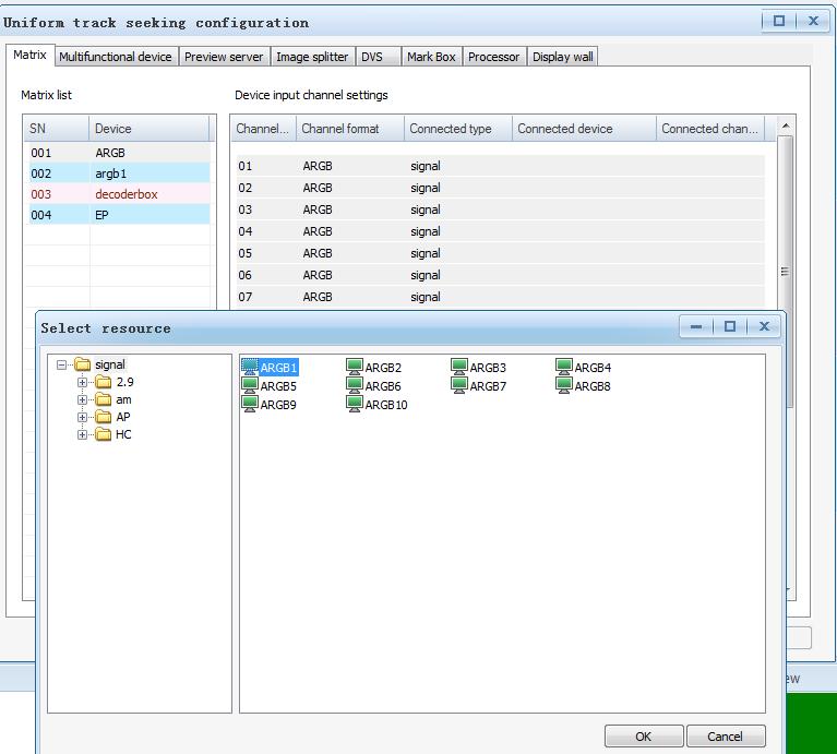
 Select the Connected type, matrix, signal source, image splitter or")
 Select the Connected device to prompt the select resource dialog box.")

42 Chapter 3 Centralized Channel Configuration 3.1 Matrix configuration Channel configuration method, taking the configuration of channel 1 as an example: 1) Select the Connected type, matrix, signal source, image splitter or processor. Select the corresponding device type according to the actual physical connection. Matrix configuration interface: 2) Select the Connected device to prompt the select resource dialog box. If a signal source is selected, the signal sources matching the matrix will be displayed in the resource list. For instance, if the matrix is an ARGB matrix, the signal sources of ARGB type will be listed. The list of added matrixes is located at the left. You can switch the matrixes using the mouse or the or key on the keyboard when a matrix is selected, the Device input channel settings at the right side will display the channel configuration information of the corresponding matrix. 3) Select the Connected channel. This option is only available for matrix, image splitter, and processor. It is not necessary for the signal source. For http : // 42


43 instance, for the cascaded matrix, the output of the upper matrix that provides input to channel 1 of this matrix shall be selected. Quick configuration: Select the starting channel, press the Ctrl key and select the items one by one, or press the Shift key and select the last item. After several channels are selected, select the connection type, device and channel, then the software will automatically fill in the subsequent fields. http : // 43

44 http : // 44

45 multifunctional device as an example: 3.2 Other device configuration The configuration of multifunctional device, image splitter, and DVS refers to the configuration of the connection device of the input channel corresponding to the device. You can select signal source, matrix or other device that can output signal source (except for the multifunctional device, which is the display terminal and cannot be used for intermediate signal output). The configuration interface and principle are the same. Through this configuration, you can establish a logic channel data structure from the signal source to the intermediate device (e.g., matrix) and to the display unit for the window opening and track seeking operation of the VWAS. Taking the configuration of http : // 45


46 3.3 Display wall configuration Click the on the Add display wall window, and then click to prompt the display unit configuration window, as shown in the following figure: There are two options for hardware control mode: network control and serial control. Option 1: Network control After selecting network control mode and online system number, then the software will automatically display the number of rows, number of columns, and Display unit model. If the displayed model is inconsistent with the actual physical device, you can manually select the display device mode or click to start automatic detection (note: the display unit cannot detect the model automatically until it is powered on), as shown in the following figure: http : // 46
.")
47 Option 2: Serial control After correctly entering the display unit configuration information, click the Save button to finish the configuration of the display unit, as shown in the following figure. After selecting the serial control mode, select the serial port number connecting the display unit, and then select the baud rate of the serial port (you can manually enter the data). Enter the corresponding number of rows and number of columns in the configuration window according to the configuration of the actual display unit, and then select Display unit model or click button to start automatic detection (note: the display unit cannot detect the model automatically until it is powered on),as shown in the following figure: http : // 47

48 To delete the display unit, click, then the display unit will be deleted. Processor configuration Click the on the Add display wall window, and then click to prompt the processor configuration window, as shown in the following figure: Select Processor type, and then enter the processor address and port information, and select online system. The details of the selected system will be displayed, as shown in the following figure: http : // 48


49 MAGIC Processor configuration: Select Magic as the processor type, as shown in the following figure: Then, enter the processor address and port information, and click. The current processor will be added to the window list, as shown in the following figure: http : // 49

 According to the actual connection relations of the Magic processor, place the Magic processor to the corresponding positions in the above figure, and then click OK to finish the configuration of")
50 Enter the corresponding number of rows and number of columns in the configuration window according to the configuration of the actual display unit (note: the numbers of rows and columns acquired by the Magic processor may be inconsistent with that of the actual display wall, because Magic can only display the numbers of rows and columns and resolution information of the processor. However, this will not affect the use, as shown in the above figure.) According to the actual connection relations of the Magic processor, place the Magic processor to the corresponding positions in the above figure, and then click OK to finish the configuration of Magic processor. After correctly entering the processor configuration information, click Save button to finish the configuration, as shown in the following figure. Click Save to prompt the layout configuration window for multiple Magic processors, as shown in the following figure: http : // 50

51 To delete the processor, click, then the processor will be deleted. http : // 51


52 Chapter 4 Mode and Workflow Select the corresponding display wall and window type, click Save temporary mode --> list to prompt the Add mode dialog box. We use the terms Mode and Workflow to describe a special type of operations defined in VWAS. Mode is used to describe a certain layout of windows in the display wall and signals associated with these windows. The term Workflow is used to describe a sequential order of Modes. 4.1 Mode management Mode editing You can add new modes through mode editing to avoid the influence on the current display status of the display wall. Select mode editing in the main menu bar. The mode editing interface will appear above the virtual display wall interface. Enter the new mode name and click OK. The mode will be added to the mode list at the left side of the mode editing interface. Select editing mode and then click Save permanent mode. The mode will be successfully added and included into the system mode list. Select editing mode, and then click execute temporary mode. The relevant mode will be executed in the actual display wall Adding a mode Click the mode button in the main function zone. Right click on the mode configuration function zone and select Add mode option in the prompted menu. The interface as shown below will appear: http : // 52
 To save the window layouts of several display walls to the same mode, you can open the windows on the displays walls through the VWAS and click the + icon, and then you can check the display walls")
53 1) Enter the mode name to the name field. 2) Select the group for the new mode in the group field. 3) To save the window layouts of several display walls to the same mode, you can open the windows on the displays walls through the VWAS and click the + icon, and then you can check the display walls you need on the prompted list. 4) Select Close all the processor signal windows, Close all the processor application windows, Close all the engine windows or Close window zone in the pre-operation. Each selection indicates that before executing the mode, all the processor windows, all the engine windows or all the windows in the specified zones of the display wall will be closed. 5) All the opened windows for the current display wall are listed in the window list. You can click move up or move down to adjust the window opening sequence in the mode. You can also select a certain window and click Delete button to remove it from the mode. 6) All the applications for the current multi-screen processor are displayed in the Application list. You can add or delete the application path. http : // 53
 Click OK button after setting, the mode will be added to the mode list. 4.1.")
54 7) The input point information of the image splitter and multifunctional device for the current display wall is listed in the signal switching list. That is, it indicates the signals accessed by the working input channel of the relevant device. 8) Click OK button after setting, the mode will be added to the mode list Modifying a mode Select the mode for modification in the mode configuration function zone on the main interface, right click and select Modify in the prompted menu, a dialog box similar to that of Adding mode will pop up, and then you can modify the mode according to the operation methods introduced in the adding operation. Click OK button to save the change Deleting a mode Select the mode for deletion in the mode configuration function zone on the main interface, right click and select Delete in the prompted menu, a dialog box for confirming the deletion will pop up. Click OK button to delete the selected mode. mode name shall be case sensitive. When adding or modifying the mode, the Delete, move up or move down operations to the mode window list will not directly affect the actual signal display window on the display wall Mode preview Click mode preview panel, and select a mode in the mode function zone on the main interface. The mode preview panel will display the contents of the selected mode, such as display wall information, window information, etc. For ARK5000 special operation are as follows: hold hotkeys ALT shortcut button to the main interface of the "mode" choose a mode of ARK5000 preview mode of operation, interface as shown in Figure, click the button on the Wall Apply that wall shows preview,click the button on the Cancel Mode Apply that the wall mode for preview is canceled Executing a mode Double click the mode name or directly press the shortcut key in the mode configuration function zone on the main interface, the mode will be executed. To execute the mode means that the display wall system will open the windows contained in the mode according to the pre-operation and window opening sequence defined when adding the mode. Note: To avoid misunderstanding, do not set the modes with duplicate name. The Mode hotkey definition The mode hotkeys can be defined in the mode hotkey settings page of the system option menu on the main interface. The hotkeys supported by the mode Ctrl + F1 ~ Ctrl + F12 are listed at the left side. All the mode resources are listed in the drop-down box at the right side. After the hotkeys are defined for the mode resources, the hotkeys supported by the current mode can be http : // 54


 Select the group for the new workflow in the group field.")
55 displayed in the mode list on the main interface. 4.2 Workflow management Adding scheme 1) Right click the workflow configuration function zone on the main interface, and select add workflow option in the prompted menu, the interface as shown in the following figure will appear: 2) Enter the workflow name to the name field. 3) Select the group for the new workflow in the group field. 4) Select the display wall that can run the workflow in the Display wall field. http : // 55
56 5) Click add mode button, and the Operation option in the Operation list will display add mode. Click the right-side arrow of the mode name list to prompt the drop-down menu, and select the mode name to be added from the mode list. 6) To increase the time delay between 2 modes, you can click add time delay button after adding a mode. Then, the time delay option will appear in the option list. Click the arrow at the right side of the option to prompt the drop-down menu, and select the time delay parameter from the time delay options. 7) To include several modes in the workflow, repeat the above operations. 8) Add power-on, "add power-off, that is, to power on or off all the display units in the display wall. Take note of the protection intervals between ON and OFF. 9) move up / move down : Select the operation item for adjustment and click move up or move down to adjust the workflow operation sequence Modifying a workflow Select the workflow for modification in the workflow configuration function zone on the main interface, right click and select Modify in the prompted menu, a dialog box similar to that of adding workflow will pop up, and then you can modify the workflow according to the operation methods introduced in the adding operation. Click OK button to save the change Deleting workflow Select the workflow for deletion in the workflow configuration function zone on the main interface, right click and select Delete in the prompted menu, a dialog box for confirming the deletion will pop up. Click OK button to delete the selected workflow Executing workflow Double click the relevant workflow in the workflow configuration function zone on the main interface or directly press the shortcut key for running the workflow, the following dialog box will appear, no matter the workflow execution mode is manual start, timed start or cycle: 10) Delete is to delete the selected operation item. 11) Three workflow execution modes are provided for setting the execution type field, including manual start, timed start and cycle. The timed start and cycle mode will be automatically executed when time is up. 12) Click OK button after setting, the workflow will be added to the resource. 13) After setting the workflow, you can define a shortcut key for the workflow, which can be used for calling the workflow. http : // 56


57 When the workflow is defined to adopt the timed start or cycle mode, all the buttons and input boxes except for the Cancel button will be disabled Workflow hotkey definition The workflow hotkeys can be defined in the workflow hotkey settings page of the system option menu on the main interface. The hotkeys supported by the workflow Shift + F1 ~ Shift + F12 are listed at the left side. All the workflow resources are listed in the drop-down box at the right side. After the hotkeys are defined for the workflow resources, the hotkeys supported by the current workflow can be displayed in the workflow list on the main interface. http : // 57
58 Chapter 5 Operations on Signal Windows hold Ctrl or Shift key according to the definition of System option display wall view and drag the signal source to the first display unit on the virtual wall. Note: Since you have completed the configuration of the display wall according to the instructions of Installation Manual, it is time to find out how to open window on the display wall and perform operations on signal windows through VWAS. 5.1 Difference between windows for optical engines and windows for processors In this user guide, windows for optical engine and engine window have the same meaning and will be used interchangeably. The signal source windows in the display wall system will be connected to the multi-screen processor window (also called processor window) of the multi-screen processor or the optical engine window of the display unit depending on the signal source access point. The window property and window opening mode are different for different access points. 5.2 To open window on display wall Opening windows for optical engines You can open the desired windows on the display wall according to the configuration information of the display unit channel of the display wall. For example, for a 2*4 display wall, the signal source Video1 is configured to the first display unit, if you want to open the window of the signal source on this first display wall, you only need to select Video 1 on the Signal source bar, then If a certain signal is not configured to the designated display unit and the operation of the window is performed on this unit, this operation will fail and the system will prompt the error message of insufficient channel. Another method of opening a window is as follows: select a signal source name to be opened in the signal source bar, press the Ctrl or Shift key according to the system option setting, and at the same time press and hold the left mouse in your desired open window position to draw a rectangle box, and then a virtual window of the rectangle box size will be opened on the display wall. Note: The successful window opening depends on the physical configuration and the relevant configuration of the VWAS software. To ensure the successful window opening, such configurations shall be conducted by the qualified and trained personnel Opening processor window You can open a desired processor window on the display wall through the VWAS software with the operation method similar to that of engine window. For detailed operation methods, please refer to the Open windows for optical engines section Opening VLINK window For the description of VLINK, please refer to the relevant product manuals of VTRON. When the processor is installed with the VTRON VLINK client, the PC http : // 58

59 terminal is installed with VLINK Server program, you can open the VLINK window in any position on the display wall by adding a VLINK signal source to the signal source field Opening multiple windows If you want to open several windows at one time, please use the mode function. 5.3 Menu for windows close all windows, tile window, full screen, and desktop mode. To close a single window: View the window style to check whether the window is locked or not. If the window is locked, first cancel the in the Lock check box to unlock the window. Right click on the unlocked window to be closed and click the Close to close the window. To close all the windows on the display wall, right click on any of the windows to be closed, and select Close all the windows, then all the current windows on the display wall will be closed. Full screen means to display the window in the full-screen mode, which fills the entire display wall. To display the window in full screen, right click on the window to be maximized and select Full screen, or double click the window, then the selected window will be maximized Window style Show/hide: To show or hide the current window. Lock/unlock: To lock or unlock the current window. To close the locked window, please cancel the lock property of the window first. Right click the window zone to prompt the right-key menu, as shown in the above Figure. You can conduct corresponding operations on the window through the right-key menu General operations for windows General operations for windows include close a window, close other windows, Window property Right click on the windows to be operated, select the Window property" on the prompted right-key menu, the Window property interface will appear. Windows may have different dialogue boxes depending on their types. The interface of the optical engine window property is as shown in the following figure. http : // 59


60 automatically restore to the default position and the parameter will use the default value. The basic properties that can be adjusted for the optical engine window include: line starting position offset, line width offset, field starting position offset and field width offset. The advanced properties for the optical engine window include brightness, contrast, sharpness, color saturation, chrominance, format, auto gain and gain Window signal path Select window signal path in the right-key menu to prompt the following dialog box, on which you can view the signal path of the window. Window type indicates whether current window is an optical engine window or a processor window. Window position indicates the position and size of the current window on the display wall. The window properties include signal parameters and window parameters. You can modify the window coordinate property on the coordinate editing box of the window parameter to move the window or change the window size. Note: It is possible that a window may span across several screens after changing the window property. In this situation, if it is an optical engine window, the display unit channel configuration of the display wall will affect the success of the setting. All the occupied display units will be shown in the engine window property (each tab stands for a display unit). You can adjust some parameters of the physical display units in every tab page. Click on the right side of the parameter bar to be adjusted, drag the rolling bar to change the parameter. If you want to use the default value, click Default button, then the rolling bar will Signal polling You can inquire and display several signal sources in sequential order and by http : // 60


61 certain interval in the selected window. Create a window on the display wall or select one or several existing windows. Right click the window and select the signal polling option in the right-key menu to prompt the following dialog box. Select the required signal sources in the signal source list and drag to the selected window one by one. The window signal source list in the signal source polling dialog box will automatically obtain these signal sources. You can adjust, modify or delete the selected signal sources. Click OK after setting to complete the signal polling setting operation. Note: For the windows started in any way other than through VWAS software, their performance on the VWAS software may be different from the actual window, such as the title bar PTZ control You can conduct PTZ operation on the camera. To enable this function, the camera must be controllable. Select a controllable camera as a signal source, and open a signal window in any position of the display wall. After the window is successfully opened, select PTZ control in the right-key menu of the window, as shown in the following figure: http : // 61

62 Chapter 6 Signal Preview and Display Wall Sharing Signal preview refers to previewing the content of a signal source before sending it to the display wall.. Display wall sharing means the content on the display wall is captured and sent to a display device for viewing or monitoring. The signal preview is realized by installing independent signal capture card. For network signals, the signal image can be obtained through network, and the preview interface is realized by plug-in. To conduct preview with VWAS, drag the signal to the preview interface. Display wall Sharing adopts sharing uses a separate display interface. 6.1 Preview server To set the preview server, click the preview server button, and right click on the preview server configuration function zone to prompt the relevant menu. Select add to prompt the following dialog box. Enter the device name, type, model, and preview server IP address then click Next. Enter the next dialog box, as shown in the following figure, and click finish to complete the configuration. http : // 62
63 6.2 Signal preview After completing the adding operation, enter the centralized channel configuration interface and select preview server, as shown in the following figure. Select the name of the preview server to be added from the device list, set the connected device type in the device input channel setting list, and select the connected device name in the resource, and then click OK to finish the preview server configuration. After the preview server configuration is finished, click signal preview. The signal preview window will appear in the configuration function zone. You can select the desired signal source in the signal source list and drag to the preview window. The number of preview windows can be set through the right mouse key. http : // 63


64 6.3 Display wall sharing Right click on the virtual display wall of the VWAS Explorer interface, select Display wall sharing on the prompted menu. The display wall sharing dialog box will be prompted. Preview effect http : // 64


65 Chapter 7 Status Information 7.1 Runtime information It mainly includes the signal source window information and the processor application information for the current display wall. The signal source window information includes two types: engine window and multi-screen processor window. The information contents include the coordinate value and window size. You can carry out some quick operations in the Runtime information bar, including Save as mode, Mode intelligent operation, and Close all the windows. The Runtime information interface is as shown in the following figure: Searching for alarm information You can search for the alarm information according to different conditions, including start time, end time and log type. The log type includes alarm and event Clearing alarm information 7.2 Alarm information The alarm log can be deleted. You can delete the alarm logs according to different conditions, including record start time, end time and log type. The alarm contents can be displayed directly or in the form of alarm information for the user. This software provides View alarm function to process the alarm information. You can access the alarm information function with the following method: Click the "alarm information" button in the main function zone. The interface is as shown in the following figure: http : // 65

66 7.2.3 Exporting alarm information The system provides the alarm log export function. Similar to the function of exporting log information, the alarm log can be exported as Excel file. To inquire real time alarm information, turn to alarm monitoring. 7.3 User logs The software has powerful log function. The log contents include daily operations and they are customizable. You can also select the logs for recording according to certain conditions. The logs can be saved, searched and printed automatically. You can access the logs with the following two methods: Click the User log button in the main function zone. The interface is as shown in the following figure: Recording daily operations The system will record all the failed operations and present them to you via logs. In this way, you can view your operation history conveniently and get informed that what operation failed. You can view any specific records through the View log Log inquiry You can enter the query conditions according to your needs, such as start time, end time, user name. These conditions can be used separately or jointly. You can also print the results Clearing log You can delete the logs according to different conditions, including record start time, end time and user name. http : // 66


67 7.3.4 Exporting log The system provides the log export function. The log you inquired can be exported as Excel file, as shown in the following figure: 7.4 Alarm monitoring You can view the real time alarm log list and clear the alarm log list. http : // 67

68 Chapter 8 Other System Settings and Custom Applications 8.1 Starting the service panel 1) Click the at the top right corner of the above figure, you can minimize the VWASPanel to the system toolbar. To restart it, double click the VWASPanel on the system toolbar. To exit VWASPanel, right click on the VWASPanel on the toolbar and select Exit in the prompted menu. To view the VWASPanel version, right click on the VWASPanel on the toolbar and select About. The service panel monitors the runtime status of software services. In the case of dual systems, both the active and standby systems are monitored. To login the VWAS client, you must ensure that all the services in VWASPanel are in ready state. You can start the VWASPanel from the Start menu: program\vwas6\vwaspanel, as shown in the following figure: 2) Service start/stop: Click Start all, then the software will start all the services one by one according to the startup dependency sequence. Click Stop all and the software will stop all the services according to the stopping dependency sequence. You can also click Start or Stop for a single service program to start or stop. 3) Hot backup status display: Heartbeat: To receive the heartbeat status from VAPServer; Data: To receive the data transmission status from VAPServer; Role: To display the master/slave service role of the control host. 8.2 System options System options provide users with system configuration, stylized grids http : // 68

69 representing display units in the display wall, mode hotkey setting and workflow hotkey setting System configuration The default is no. Debug log output on or off The default is off. Enable DVS window replacement signal If true is selected, the DVS window will not be closed during the signal switching, and only the matrix channel is switched (available only when the DVS input connects the matrix output). The default setting is true. Enable open-close dual-link If true is selected, when you open windows, the new dual-link window will be opened before the old window is closed. If false is selected, the old window will be closed before the new dual-link window is opened. Enable open-close processor windows If true is selected, when you open windows, the new window will be opened before the old window is closed. If false is selected, the old window will be closed before the new window is opened. Show the hidden window or not when applying modes If true is selected, the hidden window will be shown when applying modes. If false is selected, the hidden window will not be shown, but the window display effect is poor. The mutual permission to operate on each other s windows if two users have the same access level The default is yes. The permission to open a window across multiple processors Show the hidden window or not when opening windows by batch If true is selected, the hidden window will be shown when opening windows by batch. If false is selected, the hidden window will not be shown, but the window display effect is poor. http : // 69
 Web configuration The web client network address and port of the VWAS software 8.2.")
70 Display wall sharing server IP address The IP address and port of the computer running display wall sharing service (default port: 8020) Display wall sharing server control port The control port of display wall sharing server (default port: 8019) Web configuration The web client network address and port of the VWAS software Stylized grids for display wall You can customize the visual style of display units on the display wall, including the normal setting, default window type, auxiliary shortcut key setting and display wall style setting. Display unit power on/off prompt It determines whether to generate a prompt when the virtual display unit powers on/off. The default setting is true. Tile window prompt It determines whether to generate a prompt when conducting tile window operation. The default setting is false. Close window prompt http : // 70

71 It determines whether to generate a prompt when closing the window. The default setting is true. Default window type The default type of the window opened for the virtual display wall. Engine signal window shortcut key The shortcut key setting for opening engine signal window for the virtual display wall; the default setting is to press the shift key to open the engine signal window. The background value of the virtual display unit Display the unit frame It determines whether to display the frame of the virtual display unit. Display unit frame color The frame color value of the virtual display unit Processor signal window shortcut key The shortcut key setting for opening processor signal window for the virtual display wall; the default setting is to press the CTRL key to open the processor signal window. Multi-window selection The shortcut key setting for selecting several windows for the virtual display wall Unit 1 color The background color value of the virtual display unit when the sum of the row value and column value of the display unit is an even number Unit 2 color The background color value of the virtual display unit when the sum of the row value and column value of the display unit is an odd number Unit background Uncontrolled area The background color value of the uncontrolled area of the virtual display wall; it is reserved now. Engine signal window color http : // 71

72 The background color value of the engine signal window Processor signal window color The background color value of the processor signal window Workflow hotkey setting For details, please refer to section Mode hotkey setting For details, please refer to section appear: 8.3 User Management The user management function provides basic user information and privilege configuration. There are two roles: super administrator and common user. There is only one administrator. It account is admin and the default password is configurable. The administrator can execute add user, Modify user and "delete user" operations, while the common user can only view the basic information and authority configuration User management functions Verifying user name and password for log-in Adding, modifying, and deleting user Supporting simultaneous online operations of multiple users Supporting online operations on several clients by the same user Adding users Right click in the User panel on the main interface, and select add user option in the prompted menu, the interface as shown in the following figure will Basic information User name The name of the user to be added, which can be composed of English and Chinese characters, and the length is 1 to 37 bytes Password The password of the user to be added, whose length is 1 to 12 bytes Priority The priority of the common user; the options include high, middle and low, and the default level is middle. Allow duplicate log-in Allow the user to log in several clients with the same name. http : // 72

73 Office phone, mobile phone and The office phone, mobile phone and of the user to be added; it is an optional field. User privilege configuration The user privilege configurations specify access privilege for the following: display wall zone, signal source, mode, workflow, multifunctional device and group resource. 2. Signal source privilege All : You have the use right for the existing signal sources and the signal sources that may be added. None : You cannot operate any signal source. Custom : You can customize the signal sources to be used. 3. Mode privilege The use method is similar to that of the signal source authority. 4. Workflow privilege The use method is similar to that of the signal source authority. 5. Multifunctional device privilege The use method is similar to that of the signal source authority. 6. Group resource privilege You can set the group resources that can be operated by the common user, including the mode group resource and workflow group resource. 1. Display wall zone privilege All : You have the operation authority for all the zones of all the display walls. None : You do not have the operation authority for display wall zones. Custom : You can customize the operable zones in the existing display walls. Multiple selections are allowed. http : // 73
74 Note: In the VWAS system, you are not allowed to delete the admin user. All the deletion operations will be invalidated. To avoid misunderstanding, do not set the users with duplicate name. The user name shall be case sensitive. Common user and system administrator are subject to control zone restriction, while the super user does not have any control zone restriction. Log-in information You can view your own log-in information online. View You can view the setting information of the added user. 8.4 Importing resources Modifying users Right click the mouse and select Modify option in the prompted menu, a dialog box similar to that of adding user operation will be prompted, where you can modify the user according to the operation method introduced in the adding operation. Click OK button to save the change. The super administrator can modify all the settings of common users. A common user can only modify his information Deleting users Right click the mouse and select Delete option in the prompted menu, then the deletion confirmation dialog box will be prompted. Click OK button to delete the selected user. Note: Click Import resource on the main interface, then the Import resource interface will be prompted. The types of resources that can be imported include signal source, matrix and DVS. Operation steps: 1. Click Browse to select the edited Excel file, which shall be the VWAS resource worksheet critiera.xls under the path of program/vtron/vwas6. For details, please refer to the resource worksheet criteria description page. 2. Select one or several resource types in the Import resource type list at the left side (press Ctrl key to make multiple selections) 3. Select one or several worksheets in the worksheet list at the right side (press Ctrl key to make multiple selections) http : // 74

75 4. Click Import. 8.5 Resource backup and restore Select Save as non-zipped type.vbf6 or zipped type.cab file, as shown in the following figure: Run VWASPANEL and click the Resource backup button at the left bottom corner to enable the resource backup function, then it will save the configuration and resources in the current VWAS software, as shown in the following figure. http : // 75


76 The resource restore operation is similar to the resource backup. This operation will restore the configurations and resources from the backup file. Click the Resource restore button at the right bottom corner of VWASPANEL, the resource restore will be started. Click Save" after selecting the file type. Note that resource backup or restore can only be run when VWASService is closed. If the VWASService is not closed, relevant dialog box will be prompted. Click Yes to close VWASService and proceed with the operation. 8.6 Multi-mouse operations Execution Click Multi-mouse to prompt the following interface: If the backup is succeeded, the Operation succeeded message will be prompted, as shown in the following figure. Otherwise, an error message will be prompted. http : // 76
 IP address: the server IP address Port: the TCP port of the server 8.6.2 Connection Exit: Exit the service. 8.7 Moving caption Log-in: Enter the server IP address and port number.")


77 Account and password: The user name and password logging in the server (The default account is vtron, and the password is blank.) IP address: the server IP address Port: the TCP port of the server Connection Exit: Exit the service. 8.7 Moving caption Log-in: Enter the server IP address and port number. When the software is started, fill in the account and password, server IP address and port in the log-in verification dialog box, and then click Connect. After the connection is successfully completed, the following program interface will appear. When the log-in is succeeded, the moving (flying) caption panel will appear. Right click to apply the saved mode. Operations can be performed on local device and server, which can be switched via ALT+Z. Current mode: Only the actual operation is supported. Multi-mouse control can be enabled or disabled by clicking the Connect or Disconnect respectively. Log out: The current user exit the service. http : // 77

78 About 8.8 PowerImage Drag a local image to the virtual wall zone, the image will be displayed in full screen. Right click in the virtual wall zone, and select Exit PowerImage in the prompted right-key menu, then the image will exit from the full screen display mode. 8.9 Other functions Multiple functions are provided, including View VWAS help file, Log out user and Exit software. To provide VWAS software version information Help To provide the function of viewing the VWAS help file Web control To provide the client function of logging in VWAS WEB page Log-out To switch the users that have logged in Exit To exit the VWAS client software http : // 78


79 Chapter 9 Configuration Management for the Fly Processor (VCMS) 9.1 Configuration interface Select processor configuration in the configuration port menu. The following configuration interface will pop up: 9.2 Fly parameter configuration 1. Configure the output resolution of the Fly processor Select Digicom Fly for the processor type, and enter the IP address of the processor (factory default IP: ). 2. Configure the output row and column values of the Fly processor 3. Configure the network parameter of the Fly processor http : // 79


80 4. Set the test pattern of the Fly processor Configuration of the main Fly processor information will take effect upon modification. 9.3 Fly output mapping configuration In this section, output mapping describes the connection between the output of Fly processor and the input of display devices Method for mapping configuration: Default mapping: 1. Click the Default button. 2. Click the Save button to save the mapping relationship. Custom mapping: 1. Select one output channel (if there are many output channels, the PgUp http : // 80

81 or PgDn buttons on the right may be clicked to switch output channels). 2. Select one screen in the virtual wall, and the channel selected above will correspond to this screen, indicating that the signal output by the selected output channel will be sent to this screen. 3. Click the Save button to save the mapping. The mapping configuration of the processor will take effect when the mapping is saved Method for mapping cancellation: Partial cancellation: click the right mouse button on the screen. Complete cancellation: click the Reset button Method for mapping modification: Example: exchange the mapping between screens A and B 9.4 IP decoder card configuration Modify the network configuration of the IP decoder card, as shown in the following figure: Quick modification: 1. Click screen A. 2. Hold CTRL and click screen B. (Now the mapping relationship has been saved, and there is no need to click the Save button to save the mapping relationship.) Ordinary modification: 1. Cancel the mapping relationship of screens A and B. 2. Re-configure the mapping relationship of screens A and B. 3. Click the Save button to save the mapping. http : // 81

82 9.5 Signal monitor card configuration Modify the IP network configuration of the signal monitor card: http : // 82

83 Chapter 10 LCD Display Wall Configuration Management 10.1 Configuration interface LCD software upgrade 10.2 ON/OFF management This module provides support for turning the display wall or a single screen of the LCD display wall on or off LCD parameter adjustment (factory configuration) Factory configuration includes basic parameters and advanced parameters, with the following optional adjustments as shown in the next two figures: 1) Screen color temperature 2) Signal color temperature 3) Backlight brightness 4) Screen protection 5) GAMMA curve The LCD display wall configuration is mainly divided into six modules: ON/OFF management LCD parameter adjustment LCD status inquiry OSD menu setting 6) White balance 7) Panel selection 8) Black screen adjustment 9) Display wall splicing-seam compensation 10) Test pattern System parameter setting http : // 83


84 Save: save a group of color temperature parameters and backlight brightness values. Load: select a group of parameters from the drop-down list to load. Delete: delete a group of parameters selected in the drop-down list LCD status query This module is for querying the device status of the selected LCD display unit OSD menu setting When OSD menu is selected in the right-click menu of the LCD virtual wall interface, the following interface will pop up: Display model http : // 84


85 value of the LCD backlight brightness is 0 to System parameter configuration When configuration parameter is selected in the right-click menu of the LCD virtual wall interface, the following interface will pop up: This dialog box can be navigated with the keyboard only. You can set the value and locate the operations by pressing the up, down, left and right direction keys on the keyboard. The left and right direction keys are used for changing the value and the up and down direction keys are used for locating the option selection. Currently, only the values of the following options can be changed: display screen selection, restore default calibration values, restore default setting, and LCD backlight brightness. The other options are read only. The The parameters include: 1) Default channel: the default display signal channel of the LCD display unit will switch to the default display channel when the window is closed. 2) Time delay for sending code: time delay for sending code for the LCD serial port control command. 3) Wait time before opening the window for sync. http : // 85
86 4) Time interval for reminders to refresh: time interval for regular reminders for screen protection. 5) Automatic cross-screen-window splicing-seam compensation: shows whether the splicing-seam compensation setting is enabled for the LCD through window opening. http : // 86

87 Chapter 11 LED Display Wall Configuration Management 11.1 Configuration interface The LED configuration interface has four functional areas including device management, virtual wall, display mode, and receiver board, as shown in the figure below: an LED controller device(s) and refresh the display. Management function of the multifunction processor device: you can use this to add a multifunction processor device(s) and refresh the display. This is the property setting function of the LED controller. Multifunction processor property setting 2) Virtual wall function area: this can be used to select, add, delete and save the virtual wall. 3) Functional area of the display mode: this can be used to set the receiver board property in batches, or add and delete the display mode. 4) Functional area of the receiver board: this can be used to set the functions of the receiver board, including color temperature and brightness adjustment on the receiver board, GAMMA curve adjustment, settings related to the test pattern, and receiver board property setting scanning or adjustment Hardware device management LED controller management The LED controller is a device for controlling the signal transmission. LED controller management provides functions for adding and refreshing the LED controller. LED controller addition 1) Device management: Management function of the LED controller device: you can use this to add http : // 87

88 list in the network must be updated through this function. Click the button in the LED controller interface, as shown in the following figure: The LED controller interface is shown in the figure above. Click the button, and the LED controller window will pop up, as shown in the following figure: After clicking the refresh button, the system will check for all the LED controllers in the local area network and display them in the controller unit list below Multifunction processor management The multifunction processor is a device for controlling the switch settings. The multifunction processor provides functions for adding and refreshing multifunction processors. Adding multifunction processor Enter the IP address, mask and gateway of the LED controller in the pop-up window, and click the OK button to finish the addition of the LED controller. After finishing the above operation, the IP address of the newly added LED controller will be shown in the LED controller list. LED controller list refresh When the user increases or reduces the number of controllers, the device the The multifunction processor interface is shown in the figure above. Click button, and the multi-function processor window will pop up, as http : // 88

89 shown in the following figure: sender as well as the connection relationship between different receiver boards in the display wall. The display wall configuration provides the functions for adding, deleting, and saving the virtual wall Adding display wall Click the button in the display wall function area, and the window for adding the display wall window will pop up, as shown in the following figure. Enter the IP address, mask and gateway information of the multifunction processor in the pop-up window, and then click the OK button to finish the addition of the multi-function processor. After finishing the addition operation, the multi-function processor list will display the IP address of the newly added multifunction processor. Multifunction processor list refresh Select the multifunction processor tab and then click the button, and the system will check for all the multifunction processors in the local area network and display them in the multi-function unit list Display wall configuration The display wall refers to a set of equipment composed of several display units that are combined together and connected to the receiver board, LED controller and multifunction processor. After establishing a display wall,, you need to configure the relationship between the main/auxiliary outputs of the 1) Select the unit model in the unit configuration area. After selecting the unit model, the resolution, horizontal receiver board number and vertical receiver board number will be generated automatically. 2) Enter the name of display wall in the display wall configuration bar, and then enter the number of columns and rows of the display wall according to the actual physical receiver board. 3) Click OK to draw and generate the virtual wall in the virtual wall functional area. The generated virtual wall has 2 rows and 1 column as shown below. http : // 89
 3) Click the button in the toolbar to save the display wall settings. 11.3.3 Deleting display wall 1) Click the button in the display wall functional area, and then select the name of display wall to be deleted.")
 After deletion, click the button, and the name of display wall will no 1) Click the button in the functional area of the display wall, and then longer be displayed in the")
90 2) Select the master/slave output of the controller in the controller unit list as shown in the following figure, and then set the master/slave output position. (For detailed setting methods, please refer to ) 3) Click the button in the toolbar to save the display wall settings Deleting display wall 1) Click the button in the display wall functional area, and then select the name of display wall to be deleted. 2) Click the button in the toolbar to delete the display wall. After clicking, the following window will appear. Click the confirm button to delete the selected display wall Saving display wall 3) After deletion, click the button, and the name of display wall will no 1) Click the button in the functional area of the display wall, and then longer be displayed in the name list of the display wall. select the name of the newly added display wall. http : // 90
 Select the LED control page on the TAB controls in the device management functional area.")
91 11.4 LED controller configuration The LED controller configuration provides the functions for configuring the LED controller properties, including the input properties, output properties, test pattern, display properties, system properties and version, etc Setting LED controller properties 1) Select the LED control page on the TAB controls in the device management functional area. 2) Right click to select the IP address in the LED controller list under the controller unit, and then right click to pop up the property set menu for the controller, as shown in the following figure. 3) Click the property setting option, and the property set interface will pop up, as shown in the following figure: Setting input properties The input properties configuration provides functions for setting the input signal type and obtaining the input signal properties. Setting the input signal type When the connection of the hardware system changes, you are required to select the signal input type based on the connection relationship of the hardware system. The signal input type includes DP input, DVI input and AUTO http : // 91


92 input. You can make your selection according to your actual setup, and then click set to finish the settings for the signal input type. Getting the input signal properties Setting output properties The output properties configuration provides functions for configuring the output mode and input signal splicing mode. Select the correct input channel in the input channel selection according to the input signal type, and then click get to get the input signal properties. The interface will update the display with the input signal properties, as shown in the following figure. Setting the output mode Select output mode in the display output mode area, and then click the set button to set the display output mode. http : // 92
 Select the correct output channel in the output channel selection to output the resolution properties; 2) Select copy mode ; 3) Select the signal input")
93 Getting the output mode Click the get button in the display output mode area to update the output mode. Setting the copy mode of the input signal 1) Select the correct output channel in the output channel selection to output the resolution properties; 2) Select copy mode ; 3) Select the signal input channel in the signal 1 input channel setting, and then enter the X, Y, W and H values in the shearing area of signal 1; 4) Click the set button to set the output properties of the LED controller. Get the copy mode of the input signal Select copy mode, and then click get button to update the display of output property of LED controller. Set the splicing mode of the input signal 1) Select the output channel and output resolution properties, as shown in the following figure; 2) Select splicing mode ; 3) Select the signal input channel and then enter the X, Y, W and H values in the shearing area of input signal 1; 4) Select the signal 2 input channel, and then enter the X, Y, W and H values in the shearing area of input signal 2; 5) Click the set button to set the output properties of the LED controller. http : // 93

94 Get the splicing mode of input signal Select splicing mode and click the get button to update the display of output properties of the LED controller Test pattern configuration The test pattern configuration provides functions for testing the test pattern of the LED controller. Note: The output signal of the LED controller switches to the corresponding test pattern generated by the LED controller, including various monochromatic, color bar, grid and custom images. Get test pattern As shown in the figure, you can check the test pattern type of the master output or slave output, for example, and when the master output is selected, click the get button to update the parameters for the test pattern. Set test pattern 1) As shown in the figure, select the output channel type to perform a pattern test on the master output channel of the LED controller. 2) Select the test pattern type. Select the different picture types, and the property parameter items and sub-items will be displayed. 3) Enter optional values and sub-item values. 4) Click the set button to set the test pattern Setting LED controller display properties The LED controller display property configuration provides functions for obtaining the master/slave sender, setting the synchronization, configuring image special effects and displaying the master/slave positions. The configuration page for the LED controller display properties is shown in the following figure: Note: When setting the type of LED controller, the LED controller marked http : // 94

95 as master is responsible for generating the synchronizing signal. The default LED controller is master one. Click the get button in the synchronization set area to update the display of the synchronous mode interface. Select broadcast synchronization or looping synchronization, and then click the set button to set the synchronous mode of the LED controller. Image getting and setting by LED controller Click the get button in the image special effects area to display the acquisition of image special effects area interface. Select the master output or slave output channel. When master output is selected, check the image static option, and then click the set button to set the image special effect. Highlighted display setting of master/slave position by LED controller As shown in the figure, select the channel type in the display master/slave output position. When master output is selected, click the highlight button to identify the master output of the LED controller in the display wall; click normal to display the normal picture Setting LED controller system properties Getting the master/slave sender The controller system property configuration provides functions for setting the network parameter configuration and time configuration of the LED controller and resetting the LED controller and receiver board to their default settings. The interface is shown in the following figure: As shown in the figure, click the get button in the master/slave set area to update the type of LED controller. Synchronous sender getting and setting http : // 95


96 reset the test pattern to the default setting Setting Version information Select the version page to display the system version information of the current LED controller. Network parameter getting and setting As shown in the figure, click the get button in the network parameter setting area to display the update of the network parameter. Enter the IP address, mask, and gateway options of the LED controller, and then click the set button to set the network parameter Setting master/salve output position Time setting The date and time can be set in the time set area. Reset to default setting Click the reset to default setting button in the reset to default setting area to http : // 96
 Open the controller list, and then select the master output or slave output in the IP address option of the LED controller.")

97 1) As shown in the figure above, select the LED controller page in the device management functional area. 2) Open the controller list, and then select the master output or slave output in the IP address option of the LED controller. 3) Press the CTRL key, and select the virtual wall in the virtual wall functional area with the mouse. 5) Select access point in controller access point configuration, for example Select the sender configuration as Main controller in the master/slave controller configuration of receiver board, and then click the set button, and the following window will pop up. 4) After releasing the mouse, the window below will pop up: 6) Click the confirm button, and the color lump of the virtual wall will be shown as the following figure, which means that the master/slave output position of the LED controller is set successfully. http : // 97
 Set the master/slave output of the LED controller. For detailed operations, please refer to 11.4.")
98 11.5 Receiver board configuration The receiver board property setting mainly includes color temperature and brightness configuration, Gama curve configuration, test pattern test, scanning property configuration, acquiring channel state and version information Receiver board properties 1) Set the master/slave output of the LED controller. For detailed operations, please refer to input property configuration and output property configuration Color temperature and brightness It provides functions for brightness and color temperature adjustment. 2) Select the configured display wall. 3) Click the virtual display wall to set the properties of the receiver board, as shown in the following figure. http : // 98


99 Generating Gamma data Brightness adjustment function Check the start brightness adjustment enabled option, and then slide the brightness rolling bar to adjust the brightness or enter the brightness value directly. Click apply to finalize the brightness adjustment. Color temperature adjustment function Select the start color temperature adjustment enabled option, select color temperature mode, and then slide the red, green and blue sliding bar, or directly input the red, green and blue values to set the color temperature. Click the apply button to adjust the color temperature and brightness Gamma curve configuration The gamma curve configuration provides functions for adjusting the Gamma curve of the receiver board. Note: The Gamma curve properties for all the receiver boards corresponding to the LED controller are consistent. As shown in the above figure, check the start Gamma adjustment enabled option, select the mode in the mode field, enter the red, green and blue parameters, and then click the generate Gama data button. The Gamma curve list will update the generated data, thus finishing the generation of the Gamma data. Getting mode Gamma data As shown in the figure, select the mode in the mode filed and click the get button, and the Gamma curve list will refresh the display and update the data acquired. Gamma data in solidification mode After generating Gamma data, click the solidification button to solidify the Gama curve parameters of the receiver board Test pattern configuration of the receiver board The test pattern configuration of the receiver board provides functions for testing receiving-card picture setting and image shearing-position setting. http : // 99


100 Note: The content displayed is the corresponding test pattern generated by the receiver board, including simple images which can be generated by various monochromatic modules, color bars and other modules. Unlike the test pattern of the LED controller, not all test patterns of the receiver board can perform parameter setting. The test pattern size of the receiver board must be adjusted according to the resolution of the lamp panel driven by the receiver board. the set button to set the image shearing position Scanning property configuration As shown in the following figure, select the clock division, select the number of scanning lines, enter the minimum sub-field width, enter the minimum OE width, select the gray level, select the brightness mode and output LED port width, select the number of LED vertical ports and output horizontal blanking time, select the scan mode, select the refresh rate, select the priority option, and then click the apply button to set the scanning properties of the receiver board. Test pattern setting As shown in the above figure, select the picture number in the test pattern property, such as red, and then click set to set the pattern test of the receiver board Other properties configuration Cancel test pattern setting Click normal to cancel the setting of the test pattern and reset it to the original setting. Setting of image shearing position Enter the X, Y, W and H values in the image shearing position area, then click http : // 100
 Click the unit on the virtual wall to set the properties of the receiver board (refer to 11.5.1 operation).")

101 Getting channel state As shown in the figure above, click the get channel state button to update the display of the channel number and channel state in the channel state list. Getting the receiver board version 2) Click the unit on the virtual wall to set the properties of the receiver board (refer to operation). 3) As shown in the following figure, click the button in the display mode area to add a display mode. Click the get receiver board information button, and the version information window of the receiver board will pop up, as shown in the following figure: Display mode management 4) The following window will pop up. Enter the mode name and click the confirm button to add the new display mode. The mode list in the display mode area will display the name of the newly added display mode. Display mode management provides functions for adding and deleting display modes. Note: The display mode provides functions for saving a batch of operations of the receiver board as a display mode, to facilitate the saving and setting of the batch receiver board configurations. The display mode is mainly used to save color temperature and brightness adjustments, operations related to test patterns, and scanning property adjustments. Add display mode 1) Click the button in the control area of virtual wall to select the correct name of the display wall. Deleting display mode Select the name of the display mode to be deleted in the display mode list, and then click the button, and the following window will pop up. After clicking the confirm button, the name of the display mode will be deleted in the display mode list. http : // 101

 Click Property set and the following window will pop up: Executing display mode Select the name of the display mode to be executed in the")

102 shown above. Right click the IP address of the multifunction processor in the multifunction unit list, and the menu for setting the properties of the multifunction processor will pop up. 2) Click Property set and the following window will pop up: Executing display mode Select the name of the display mode to be executed in the display mode list, right click to pop up the figure below, and then select apply mode to execute the display mode. The mode execution result shows the batch property setting of the receiver board Multifunction processor configuration Configuring multifunction processor properties Configuring the multifunction processor timer 1) Select Multifunction in the equipment management functional area, as The timer configuration of the multifunction card provides functions for getting, deleting and adding timers. http : // 102
103 Note: For the display wall s power supply, the timer of the multifunction card can trigger the switch according to the preset time, so that the switch of the multifunction processor can be powered on or off on a timed basis. Timer getting (displaying timers) Click the get button in the multifunction card timer area, as shown below, to refresh the display of the timer list. Select the ID of the timer from the list and click the delete button to delete a timer with certain ID. Timer adding (adding timer) As shown above, input the ID value in the multifunction card timer area, select the timer type (e.g., Single ), select the serial number, select the switch status of the single serial number, select the loop option, select the start option, set the date and time, select the loop mode (Year/Month/Day/Week), click the add button, and the display of the ID serial number in the timer ID list will be updated Configuring the multifunction processor switch Configuration of the multifunction card switch provides dynamic creation of groups of multifunction card switches, control of switches in the group, and control of all multifunction card switches. Timer deleting http : // 103

104 In the area all, click the close button under whole to close all multifunction card power switches, and meanwhile all buttons will change to the status of open Configuring the multifunction processor system The configuration of the multifunction card system provides settings for the network parameters and the time for the multifunction card. Setting the system network parameters supports the mode of TCP unicast. Setting of group power switches 1) As shown above, select item 1 in the group switch list on the left, click the ==> button, and item 1 will be added in the switch list on the right. Click the create button to generate the button for the configuration of the group switch. 2) Click the corresponding button to open or close a switch. Setting of all power switches Network parameter setting and getting As shown above, input the IP, mask and gateway options of the multifunction card in the area of network parameter setting, and click the set button to set http : // 104
105 the network parameters. Click the get button to update the display of the network parameters. Setting of the multifunction processor time The date and time can be modified in the area time set. Click the set button to set the time for the multifunction processor. Click the get button to get and synchronize the time display of the multifunction processor, as shown in the following figure: http : // 105

 Title bar logo, main menu, and minimize and close buttons 2) Model/workflow list Input the correct server")
106 Chapter 12 LCD/LED Operating Terminal 12.2 The main interface This chapter mainly describes the method of operations using the VCMS operating terminal Login The main interface of the VCMS operating side comprises the following six parts: 1) Title bar logo, main menu, and minimize and close buttons 2) Model/workflow list Input the correct server IP address, username and password in the login page and click Login, and then a successful login will be achieved. If Remember is selected, a direct login will be achieved the next time. 3) Window operation toolbar 4) Virtual wall and switching menu 5) Signal source list 6) Alarm information and user login status bar 12.3 Main menu operations Click the LOGO at the top left corner of the page, and the drop-down menu will pop up, as shown below: http : // 106


107 Event query Select Event, Start time and Over time and click the Query button, and then detailed event information will be shown in the relevant information bar. Function of page turning Alarm information Click Alarm in the main menu to enter the page with the alarm information. One page shows 20 pieces of information by default, and Current Page, Total Page and Total Num may be queried in the page information area as required. In the page turning area, First Page, Previous Page, Next Page and Last Page may be selected to view details. Input the page number to be found and press the Enter key, and then the alarm/event information of the corresponding page will be shown in the page Matrix switching Click Matrix in the main menu to go to the page about matrix switching. Alarm query Alarm is selected by default. Select Level, Start time and Over time and click the Query button, and then detailed alarm information will be shown in the relevant information bar. One-to-one switching http : // 107


108 Select a matrix name from the matrix list; Select one input channel in the input channel area; Select one output channel in the input channel area. One-to-all switching Select a matrix name from the matrix list; Select one input channel in the input channel area; Select All out in the input channel area. This version supports both one-to-one and one-to-all switching About Clicking About will lead to the display of information about the version, as shown below: Click Yes to quit the program, or click No to return to the main interface Minimize and close Click the Minimize or Close button to minimize the interface or close the program Mode and workflow Mode list Logout Clicking "Logout" in the main menu will lead to returning to the login page Exit Click Exit and the following prompt will pop up: Click the established mode in the mode list to view the mode of the tree structure. In the operation of this software, there are two types of mode execution operations, namely, double-click execution and right-click menu execution. http : // 108
 Click Preview to view information about the mode in the popped up page, as shown below.")

109 Execution of mode by double clicking Double click the name of the mode to be executed, and the mode will be executed. Execution of mode by right-click menu 1) Click Preview to view information about the mode in the popped up page, as shown below. Clicking Action in the preview window can also lead to the execution of the mode. 2) Click Action in the right-click menu to execute the currently selected mode. Model action means that the display wall system will open all windows included in the mode in the pre-operation and window-opening sequence defined at the time when the mode is added Workflow list Select one workflow, and enter the workflow page (as shown below) by double clicking or selecting Action in the right-click menu. http : // 109


110 12.5 Operations of the virtual wall Virtual wall switching Click the drop-down box of the large wall list in the middle of the main interface, and select different wall names to switch the walls Virtual wall Manual execution Select Perform time button, input the number of times, click Perform, and then the workflow will be executed. Forever execution Select Perform forever, and the option to input the number of times disappears. Click Perform, and then the workflow will be executed. During execution of the workflow, the Pause and Stop buttons can be used respectively for pausing and stopping the execution of the current workflow. Clicking Close will lead to quitting the workflow operation page. The virtual wall in the main interface shows the number of rows and columns and window information of the current large wall. http : // 110
111 Toolbar of the virtual wall window Display wall sharing The sharing button is located on the left side of the toolbar in the main interface. Click the Sharing button to open or close the Sharing. Close Sharing is the default status of the program. The signal of the opened window will be shown in the virtual wall if Sharing is open, and the default window pattern will be shown if Sharing is closed. Type of opened window The VCMS software supports Processor window and Through window, while VEMS only supports Processor window. The processor window is selected by default. The window type may be switched by clicking before opening the window. Display model Select the model from the drop-down list of display models and execute it. Splicing-seam compensation VCMS supports the function of splicing-seam compensation, and the compensation will be executed after clicking. VEMS does not provide this function. Window operation Drag a signal from the signal source list to the virtual wall and release it, and then quick operations on the window may be performed after the window is successfully opened in the virtual wall. Those operations are closing the window, closing all windows, full screen of the window and window extension. Specific operations are as follows: Select one window, and click the button to close the window. After the command has successfully executed, the window will be closed both in the large wall and the virtual wall. Click the button to close all windows. After the command has successfully executed, all the windows in both the large wall and the virtual wall will be closed. Select one window and click the button to perform the operation of full screen, and the window will be extended to the maximum size in the effective range; click the button once more, and the window will be restored to its original size. Select one cross-screen window and click the button to execute the extension operation, and the window will spread over the occupied unit; click the button once more, and the window will be restored to its original size Turning display wall ON/OFF The two buttons are respectively for Display wall ON and Display wall OFF. Click the Display wall ON/OFF button to perform the ON/OFF operation. http : // 111


112 12.6 Signal source list The signal source list is located in the lower right area of the main interface and can be shown in preview or list mode. In the preview mode, multiple signal sources may be previewed at one time, and in the list mode, the signal sources are shown in categories with smaller icons and only one signal source may be dragged at a time for preview. The preview mode is selected by default Preview mode Drag a signal source from the list to this window to preview this single signal source Signal query Open the folder to view the signal source. 7-8 signal sources can be previewed at one time. Drag left or right leads to page turning for viewing other signal sources List mode Fuzzy query is supported. Input the keyword in the input box and click the query button. All signal sources in the signal source list whose name includes the keyword will be shown (if any). For example, all signal sources whose name includes the letter a are found when a is input, as shown below: Opening window The signal sources are shown in a compact manner. When the number of rows and columns of the large wall are relatively large, this mode may be used to open the window by dragging the signal source. In the VCSM software, the window type must be selected first, and the processor window is selected by default. If the large wall has been correctly configured, drag a signal source from the signal source list to the virtual wall and release it at a certain position. Upon successful opening of the window, a window will open in the virtual window and a corresponding window will open in the actual wall, and the name and contents of the signal source will be shown. http : // 112

113 Replacing window When there are open windows in the virtual wall, drag a signal from the signal source list to a window that already has a signal, pause for a moment and release it after a red box appears, and the window replacement is finished Alarm and login status bar Click to enter the alarm page to view alarm or event information; refer to Section Alarm information for details. The current server IP address, user name and authorized user are shown in the login status bar Moving window Select a window with a signal from the virtual wall, and move the window to a certain position and release it. The window will open at the new position and disappear at the original position. If the moving operation fails due to channel configuration, there will be a prompt and the window will not change at the original position Zooming window Mode 1: The window can be zoomed by dragging the mouse at one of the four edges of the window. After zooming, the size of the window in the actual large wall will be changed accordingly. Mode 2: For a cross-screen window, zooming in or returning it to its original size can be achieved by double clicking. http : // 113


114 Chapter 13 Web Client 13.1 Interface Processor status You can view the status of the physically connected processor: The web client includes 4 modules: Status monitoring Function control System management Update management 13.2 Status monitoring Engine status You can view the status of the physically connected engine: http : // 114


115 User operation log Device event log Log inquiry: You can enter the inquiry conditions according to your needs, such as start time, end time, user name. These inquiry conditions can be used separately or jointly. You can also print or delete the inquiry results. If any error occurs when the hardware is executing the command, the system will record the event content into the device event log. You can set the start time and end time for viewing the log. You can also print the event log or delete the selected event, as shown in the following figure: Device alarm log Alarms and warnings may be generated based on hardware or software exceptions, events, or certain conditions. http : // 115


116 13.3 Function control 13.5 Update management The following functions are provided for display units: open window, close window, close all the windows, expand window, window in full screen, lock window, hide window, normal setting, display wall ON, display wall OFF, signal source replacement, switch virtual wall. Other functions include mode inquiry and execution, signal source and multifunctional device viewing, matrix and channel inquiry and channel switching. You can upload, download and delete the software package and plug-in patch package. When you log in the desktop client, the system will automatically detect the uploaded software package and plug-in patch package and ask your permission to install. No installation prompt will be provided of the installed software package and plug-in patch package System management For the functions of this module, please refer to section of the Installation Manual. http : // 116
117 Chapter 14 FAQ and Troubleshooting Question 1: The VWAS display wall manager client could not be logged in. Troubleshooting: Solution 1: check if the control host IP address is correctly entered. Solution 2: Check if the user name and password are correct. Solution 3: Check if the service of the VWAS server has been started via the VWASPanel tool. Question 2: Can I use other browsers apart from IE and Firefox? Answer: Different browsers may affect some interfaces of the VAWS software and WEB client, therefore it is advised not to use other browsers. Question 3: The Vclord and Vport services in the VWASPanel could not be started. Troubleshooting: Please check if the ports necessary for these services are occupied. The ports for VWAS6.0 services are as follows: Service name port Vclord 5800 and 5801 Vport 5962 VWASService 8989 AmxControl 5999 VWASWebSrv 80 Question 4: The engine could not be registered, and the system provided a prompt that it was offline. Troubleshooting: Please check if the network is disconnected, and the network cable is plugged out. Question 5: When I checked VWAS6.0 Panel after installing the VWAS6.0, I found that the VWASWebSrv service was in uninstalled state, while other services could be run normally. Troubleshooting: Please check if the time zone information is normal: Open control panel/date and time/time zone. If the time zone option is not available or there is only an option, or the time zone map is incomplete (in normal situation, there should be a world map), it indicates that the time zone is abnormal. You should recover the time zone first. Solution: Export the HKEY_LOCAL_MACHINE\SOFTWARE\Microsoft\WindowsNT\CurrentVersion \Time Zones from the registry of a computer with normal XP system to a file, and then copy the file to the computer that needs to recover the time zone. Double click to run this execution file. After the import is completed, restart the computer, and the time zone will be recovered. After the time zone is recovered, you can manually install the WEB services: Open the CMD, enter the WEB service directory of the VWAS6 (C:\Program Files\VTRON\VWAS6\webapp), and then run VWASWebSrv.py --startup auto install. Question 6: When the preview is enabled, the prompt of please install the VLC player will appear. Troubleshooting: please install V2.0.7 or V2.08 VLC player. The software does not support other versions. Question 7: The Excel file cannot be imported. Troubleshooting: Please install the Office software. Question 8: The software was not compatible with some antivirus software. http : // 117
118 Troubleshooting: The VWAS6.0 is only compatible with 7 types of antivirus software: Kingsoft, 360, Rising, Kaspersky, Norton, nod32 and MSE. Question 9: The VLinkVLink window could not display image. Troubleshooting: Solution 1: Check if the VLinkVLink signal source is installed with VLink server, and if the version is compatible. Solution 2: Check if the firewall for the VLink signal source is closed. Solution 3: Check if the network is disconnected. Question 10: The Ark processor got online and offline frequently. Troubleshooting: Please check if the there is any conflict with the IP address. Question 11: The XLAN processor had a problem similar to this: When a VLink window is opened after the video window is opened, the video window will disappear, and only the VLink window will be display. Troubleshooting: This is due to the XLAN resource restriction. The window that is faster to be opened and displayed will be maintained. Although VIDEO window is opened before the VLINK window by the VWAS software, the processor has different speeds for opening different signal windows. If VLink is opened faster, the Video window cannot be opened. Question 12: When the PC (especially the win 7 system) sleeps for a certain period of time, the web service would be disconnected, and the VWAS6.0 server would also be disconnected with the client. Troubleshooting: Please cancel the sleep setting of the control PC (especially the win 7 system) according to the following methods: Method 1: Select Start control panel to open the Win7 control panel, find and open power option, and then click Modify computer sleep time in the power option window to open the corresponding setting page. Select never for the two setting options of Get the computer into sleep state field, and then click Save the change to save the new setting. Method 2: Select Start all programs- auxiliaries - notepad to create a notepad window. Enter or copy command (copy the bolded part) to the notepad and save as a any file name.bat file, such as disable sleep.bat or enable sleep.bat, as shown in the following example (the file name is aa.bat).run the batch processing files created by right key as an administrator and finish the command. Question 13: After modifying the row/column value or system number in the VCLORD, I could not open the window. Troubleshooting: after modifying the row/column value or system number in the VCLORD, you must power off the engine before you can open the window. Question 14: The application cannot be started. Troubleshooting: Solution 1: Please check if the application path is correct. Solution 2: Please check if the application path contains space. If yes, quotation mark should be added. Solution 3: You cannot use many processors to open windows for the application. Question 15: When I used the VCLORD of VWAS5.5 or VEXTuner together with VWAS6.0, VWAS6.0 could not be normally used. Troubleshooting: The VCLORD version of VWAS5.5 and VEXTuner are lower, and VWAS6.0 is not compatible with them. You can use the VCLORD of VWAS6.0. Question 16: After logging in the Web, some operations became abnormal. For example, when all the windows were closed, all the display walls disappeared. Troubleshooting: Solution 1: Please clear the cache of the browser. Solution 2: Please set the compatible view of the browser. http : // 118

119 VWAS6.0 日常使用手册
NVMS User Manual. Version 2.1.0
 NVMS-1000 User Manual Version 2.1.0 Contents 1 Software Introduction... 1 1.1 Summary... 1 1.2 Operation Environment... 1 1.3 Install and Uninstall... 2 1.3.1 Install the Software... 2 1.3.2 Uninstall
NVMS User Manual
 NVMS-1000 User Manual Contents 1 Software Introduction...1 1.1 Summary... 1 1.2 Operation Environment... 1 1.3 Install and Uninstall... 2 1.3.1 Install the Software... 2 1.3.2 Uninstall the Software...
MagicInfo VideoWall Author
 MagicInfo VideoWall Author MagicInfo VideoWall Author User Guide MagicInfo VideoWall Author is a program designed to construct a VideoWall layout and create VideoWall content by adding various elements
Aurora Multi-image System Control Software. User Manual
 Aurora Multi-image System Control Software User Manual Product Information Model: Aurora Controller Software Version: V010200 Release Date: January 18th, 2017 Company OSEE TECHNOLOGY CO., LTD. Contact
NVMS User Manual
 NVMS-1000 User Manual Contents 1 Software Introduction...1 1.1 Summary... 1 1.2 Operation Environment... 1 1.3 Install and Uninstall... 2 1.3.1 Install the Software... 2 1.3.2 Uninstall the Software...
USER MANUAL. Mac Version
 USER MANUAL Mac Version Contents 1 Software Introduction... 1 1.1 Summary... 1 1.2 Install and Uninstall... 1 1.2.1 Install the Software... 1 2 Login Software... 3 2.1 Login... 3 2.2 Control Panel Instruction...
Siera CMS Panther v3.0
 1 This manual maybe exist inexact in technology, product feature, operation discrepancy or misprint. The content of the manual will renew according to the product function enhance, and regular change or
NVMS1000. User Manual
 NVMS1000 User Manual Contents 1 Software Introduction... 1 1.1 Summary... 1 1.2 Operation Environment... 1 1.3 Install and Uninstall... 2 1.3.1 Install the Software... 2 1.3.2 Uninstall the Software...
Viewer for Luma Fisheye IP Surveillance Camera. Software Manual
 Viewer for Luma Fisheye IP Surveillance Camera Software Manual Important Notes This software is a third-party program that allows you to view, in a normal view, surveillance recordings that were made in
Video Surveillance Management Software NVClient V5 User Manual
 Video Surveillance Management Software NVClient V5 User Manual Version: V5.0 Update Date: 2013-12-12 Welcome Thanks for using the Company's digital video surveillance management software. Please read this
Central Management Software for NVR-915 / NVR-1615 CV5-M256
 Central Management Software for NVR-915 / NVR-1615 Table of Contents Chapter 1. Main Console... 4 1.1 Tool Bar... 4 1.2 NVR List... 5 1.3 Division List... 7 1.4 Group List... 9 1.5 PTZ Panel...11 1.6 Operation
VMS-A1 Client Software. User Manual
 VMS-A1 Client Software User Manual Contents Contents... 2 Chapter1. Overview... 4 1.1 Description... 4 1.2 Features & Functions... 4 Chapter2. Update Info... 6 Chapter3. Starting VMS-A1... 7 3.1 Installing
NVMS1000. User Manual
 NVMS1000 User Manual Contents 1 Software Introduction... 1 1.1 Summary... 1 1.2 Operation Environment... 1 1.3 Install and Uninstall... 2 1.3.1 Install the Software... 2 1.3.2 Uninstall the Software...
W-E
 Signage Suite V2.20 User Guide 605220-02-01-W-E-051613-02 Trademarks Windows XP, Windows Vista, Windows 7, and Microsoft are registered trademarks of Microsoft Corporation. All other trademarks are the
Player Operation User s Manual
 Player Operation User s Manual Version 1.0.0 Table of Contents 1 General Introduction...1 1.1 Overview...1 1.2 Features...1 2 Installation...2 2.1 Open Player...5 3 Operation...7 3.1 Main Interface...7
IMS Client Operation Guide Version V1.1 Date
 Version V1.1 Date 2015-10-20 About This Document About This Document About This User Manual Please note the following points before using this user manual: This user manual is intended for persons who
Quick Operation Guide of ivms-4200
 Quick Operation Guide of ivms-4200 V1.02 2012-02-22 Description ivms-4200 is a video management software using a distributed structure to manage all the connectable devices. It can manage the NVR, DVR,
DCMS. User Manual. Version V1.0
 DCMS User Manual Version V1.0 About This Document About This Document About This User Manual Please note the following points before using this user manual: This user manual is intended for persons who
Manual Version: V1.15. Video Management Software Guard Station User Manual
 Manual Version: V1.15 Video Management Software Guard Station User Manual Thank you for purchasing our product. If there are any questions, or requests, please do not hesitate to contact the dealer. Disclaimer
Manual Version: V1.01. Video Management Server Client Software User Manual
 Manual Version: V1.01 Video Management Server Client Software User Manual Thank you for purchasing our product. If there are any questions, or requests, please do not hesitate to contact the dealer. Notice
Intelligent Security & Fire Ltd
 Copyright 2007-2009 Cortex Global Table of contents: Introduction... 3 1. Login... 3 1.1 Advanced login options... 4 2. Preview... 5 2.1 Main menu... 6 2.2 Camera list... 6 2.3 Main display... 6 2.4 Maps...
VMS2.0 Client Software. User Manual
 VMS2.0 Client Software User Manual Chapter 1 Contents Brief Introduction...1 1.1 Description... 1 1.2 Running Environment...1 Chapter 2 Installation... 2 Chapter 3 Live View... 4 3.1 User Login...4 3.2
Central Management Software. Cam Viewer 3 Lite. User Manual
 Central Management Software Cam Viewer 3 Lite User Manual Version 1.0.0 Table of Contents 1. System Requirement...4 2. Software Installation...5 3. Configuration Wizard...9 3.1 Channel...10 3.1.1 Adding
ivms320 Platform User Manual
 ivms320 Platform User Manual Version: 9.1.8.5 Table of Contents Chapter 1 Overview... 4 1.1. Description... 4 1.2. Installation... 4 1.3. Uninstallation... 10 1.4. Log in... 13 1.4.1. First Login... 13
NETWORK PRINT MONITOR User Guide
 NETWORK PRINT MONITOR User Guide Legal Notes Unauthorized reproduction of all or part of this guide is prohibited. The information in this guide is subject to change for improvement without notice. We
VSPlayer Software User Manual
 VSPlayer Software User Manual UD03888B User Manual COPYRIGHT 2016 Hangzhou Hikvision Digital Technology Co., Ltd. ALL RIGHTS RESERVED. Any and all information, including, among others, wordings, pictures,
Quick Start Guide (V1.03) UD.6L0201B1064A01
 UD.6L0201B1064A01") ivms-4200 PCNVR Quick Start Guide (V1.03) UD.6L0201B1064A01 Thank you for purchasing our product. If there is any question or request, please do not hesitate to contact the dealer. This manual applies
ivms-4200 PCNVR Quick Start Guide (V1.03) UD.6L0201B1064A01 Thank you for purchasing our product. If there is any question or request, please do not hesitate to contact the dealer. This manual applies
SOFTWARE INSTRUCTIONS DIGITAL SPEAKER PROCESSOR DP-SP3
 SOFTWARE INSTRUCTIONS DIGITAL SPEAKER PROCESSOR DP-SP3 Thank you for purchasing TOA s Digital Speaker Processor. Please carefully follow the instructions in this manual to ensure long, trouble-free use
HIP2P Network Video Camera Client Terminal User Manual
 HIP2P Network Video Camera Client Terminal User Manual Document version:5.1 Page 1 of 34 } Preface Thank you for using our company's products. The network video camera client terminal is used to implement
Secure Guard Central Management System
 Speco Technologies, Inc. Secure Guard Central Management System Usage Information Contents 1 Overview... 7 2 Installation... 7 2.1 System Requirements... 7 2.2 System Installation... 7 2.3 Command Line
Avigilon Control Center Web Client User Guide
 Avigilon Control Center Web Client User Guide Version: 4.12 Standard PDF-WEBCLIENT-S-E-Rev2 Copyright 2013 Avigilon. All rights reserved. The information presented is subject to change without notice.
Getting Started. Microsoft QUICK Source 7
 Microsoft QUICK Windows Source 7 Getting Started The Windows 7 Desktop u v w x u Icon links to a program, file, or folder that is stored on the desktop. v Shortcut Icon links to a program, file, or folder
Figure 4-9. Click Finish button, system pops up a dialogue box. Click the OK button, the startup wizard is complete. See Figure 4-10.
 For detailed information, please refer to chapter 4.11.4.1.1. Figure 4-9 Finish button, system pops up a dialogue box. the OK button, the startup wizard is complete. See Figure 4-10. Figure 4-10 4.4 Preview
KMnet Viewer. User Guide
 KMnet Viewer User Guide Legal Notes Unauthorized reproduction of all or part of this guide is prohibited. The information in this guide is subject to change for improvement without notice. We cannot be
Leyard TVH Series and Leyard TW Series. Software User Manual
 Leyard TVH Series and Leyard TW Series Software User Manual 1 Copyright 2016 by Leyard Optoelectronic Co., Ltd. All rights reserved. The contents of this publication may not be reproduced in any form without
32 CHANNEL SURVEILLANCE SYSTEM MANUAL
 32 CHANNEL SURVEILLANCE SYSTEM MANUAL English version 1.0 SOFTWARE GUIDE Software Guide for Digimerge Networkable Cameras Copyright 2007 Digimerge Technologies Inc. 32-CH Surveillance System Note This
W Box VMS BOX T E C H N O L O G I E S.
 W Box VMS BOX T E C H N O L O G I E S www.wboxtech.eu Contents Contents... 1 Overview... 3 1.1 Description... 3 1.2 Running Environment... 3 1.3 Function Modules... 3 Live view... 6 2.1 User Registration
User Manual of VSPlayer Software. VSPlayer Software. User Manual UD06784B
 VSPlayer Software User Manual UD06784B i User Manual COPYRIGHT 2017 Hangzhou Hikvision Digital Technology Co., Ltd. ALL RIGHTS RESERVED. Any and all information, including, among others, wordings, pictures,
Avigilon Control Center Standard Web Client User Guide. Version 5.6
 Avigilon Control Center Standard Web Client User Guide Version 5.6 2006-2015, Avigilon Corporation. All rights reserved. Unless expressly granted in writing, no license is granted with respect to any copyright,
CHAPTER 1 COPYRIGHTED MATERIAL. Getting to Know AutoCAD. Opening a new drawing. Getting familiar with the AutoCAD and AutoCAD LT Graphics windows
 CHAPTER 1 Getting to Know AutoCAD Opening a new drawing Getting familiar with the AutoCAD and AutoCAD LT Graphics windows Modifying the display Displaying and arranging toolbars COPYRIGHTED MATERIAL 2
Manual Version: V1.01. ISS Manager Video Management Software User Manual
 Manual Version: V1.01 ISS Manager Video Management Software User Manual Notice The information in this manual is subject to change without notice. Every effort has been made in the preparation of this
Table of Contents. Tops Digital Solutions DVS 2000 Series Users Manual Ver.2.0 2
 DVS 2000 Series Table of Contents Ch. 1. Preface 4 How to Use This Guide... 4 Conventions 4 Related Documents... 4 Support.. 5 Safety Warnings and Information.. 5 Ch. 2. Overview. 6 Overview 6 Features..
DSS Professional FAQ. Ver:
 DSS Professional FAQ Ver: 7.00.000 Contents 1 Installation and Deployment... 1 1.1 What kind of OS can install DSS Professional?... 1 1.2 What kind of performance of server can install DSS Professional?...
TOF-Watch SX Monitor
 TOF-Watch SX Monitor User manual Version 1.2 Organon (Ireland) Ltd. Drynam Road Swords Co. Dublin Ireland Contents General information... 3 Getting started... 3 File Window... 7 File Menu... 10 File Open
WINDOWS NT BASICS
 WINDOWS NT BASICS 9.30.99 Windows NT Basics ABOUT UNIVERSITY TECHNOLOGY TRAINING CENTER The University Technology Training Center (UTTC) provides computer training services with a focus on helping University
Dahua Player3.1 Operation User s Manual
 Dahua Player3.1 Version 1.0.0 Table of Contents 1 General Introduction... 1 1.1 Overview... 1 1.2 Features... 1 2 Installation... 2 2.1 Open Player... 5 3 Operation... 6 3.1 Main Interface... 6 3.2 Menu...
Centralized Monitoring Management Platform. Manual
 Centralized Monitoring Management Platform Manual 3 Contents 1. Products... 5 1.1. Summary... 5 1.2. Application Environment... 5 1.3. Install and uninstall... 6 2. Centralized Monitoring Management Platform
LED STUDIO USER MANUAL
 BLAIR COMPANIES LED STUDIO USER MANUAL Part # 33-19-14 5107 Kissell Avenue Altoona PA 16601 814-949-8287 blaircompanies.com TABLE OF CONTENTS Chapter 1 Introduction... 1 Chapter 2 Install and Uninstall...
Contents. 1.2 Software Installation... 1
 Software Manual Contents 1 Software Installation... 1 1.1 Overview...1 1.2 Software Installation... 1 2 Introduction To Basic Function...5 2.1 Login System... 5 2.2 CMS Operating Interface...5 2.2.1 Operating
VSPlayer Software User Manual
 VSPlayer Software User Manual UD.6L0202D1505A01 Thank you for purchasing our product. This manual applies to VSPlayer software, please read it carefully for the better use of this software. This manual
Video Management Software User Manual
 Video Management Software User Manual Manual Version: V1.02 i Thank you for choosing our product. If there are any questions, or requests, please do not hesitate to contact the dealer. Disclaimer CAUTION!
Contents. 1.2 Software Installation... 1
 Software Manual Contents 1 Software Installation... 1 1.1 Overview...1 1.2 Software Installation... 1 2 Introduction To Basic Function...6 2.1 Login System... 6 2.2 CMS Operating Interface...6 2.2.1 Operating
EasyMeeting Application Software Instructions
 EasyMeeting Application Software Instructions Contents 1.Introduction to the software... 1 2.Installation instructions... 2 2.1 Running Environment... 2 2.2 To install EasyMeeting... 2 3.Use description...
Matrox MuraControl for Windows
 Matrox MuraControl for Windows User Guide (for software version 6.00) 20179-301-0600 2017.09.25 Contents About this user guide... 6 Using this guide... 6 More information... 6 Overview... 7 Supported Matrox
SEWCAT USER MANUAL V APRIL 14, 2017 S & S COMPUTING Oak Ridge, TN 37830
 SEWCAT USER MANUAL V4.0.6 APRIL 14, 2017 S & S COMPUTING Oak Ridge, TN 37830 Contents 1. Introduction... 3 1.1 Getting Started... 3 1.2 Frequently Asked Questions (FAQ)... 5 1.3 Contact Us... 5 1.4 Purchase
Infinova 2217 Security Management System Client User Guide
 Infinova 2217 Security Management System Client User Guide April 2015 Page 1 of 90 Contents 1. Quick Start... 4 1.1 Installing application... 4 1.2 Launching application... 4 1.3 Login... 4 2. Main screen...
Matrox MuraControl for Windows
 Matrox MuraControl for Windows User Guide (for software version 7.00) 20179-301-0700 2018.06.12 Contents About this user guide... 6 Using this guide... 6 More information... 6 Overview... 7 Supported Matrox
Breeze User Guide. Breeze Multiple Stream Video Processors. Light and Standard Editions Version 5.3.2
 Breeze User Guide Breeze Multiple Stream Video Processors Light and Standard Editions Version 5.3.2 Copyright 1989-2007 Discovery Scientific, LLC All rights reserved www.discoverybiz.net January 01, 2007
LED VIDEO WALL CONTROLL SYSTEM USERS MANUAL. PAW GmbH 04/2013 1
 LED VIDEO WALL CONTROLL SYSTEM USERS MANUAL PAW GmbH 04/2013 1 INDEX 1 INHALT 2 INTRODUCTION... 6 2.1 Features... 6 2.2 Operating Environment... 6 2.2.1 Operating system... 6 2.2.2 Hardware Configuration...
Tach Facts V3.0 Software
 Tach Facts V3.0 Software Download runs from your Auto Meter Playback Tach with Tach-Facts Software. Instr. No. 2650-978 Tach Facts provides complete race analysis on your personal computer. Introduction
NVMS-5000 NVMS User Manual
 NVMS-5000 NVMS-5000 User Manual NVMS-5000 User Manual Contents 1 Introduction... 4 1.1 NVMS-5000 Brief Introduction... 4 1.1.1 Summerization... 4 1.1.2 Software Architecture... 4 1.2 System Components...
GV-IP Decoder Box Plus User s Manual
 GV-IP Decoder Box Plus User s Manual Before attempting to connect or operate this product, please read these instructions carefully and save this manual for future use. DBPV10-UM-A 2015 GeoVision, Inc.
HikCentral Control Client. User Manual
 HikCentral Control Client User Manual Legal Information User Manual 2018 Hangzhou Hikvision Digital Technology Co., Ltd. About this Manual This Manual is subject to domestic and international copyright
Akkadian Console 4.0
 Akkadian Console 4.0 User Guide Copyright and Trademarks: I. Copyright: This website and its content is copyright 2015 Akkadian Labs, LLC. All rights reserved. Except with the prior written permission
Video Management Software
 Video Management Software User Manual Web: europesecurity.eu Mail: info@europesecurity.eu Tel.: 0541 352 952 User s Manual 2 Contents CHAPTER : XMS CENTRAL USER MANUAL 1 PC REQUIREMENT 3 2 INSTALL 3 3
Sage Getting Started Guide. September 2017
 Sage 100 2018 Getting Started Guide September 2017 2017 The Sage Group plc or its licensors. All rights reserved. Sage, Sage logos, and Sage product and service names mentioned herein are the trademarks
Creating a Website in Schoolwires
 Creating a Website in Schoolwires Overview and Terminology... 2 Logging into Schoolwires... 2 Changing a password... 2 Navigating to an assigned section... 2 Accessing Site Manager... 2 Section Workspace
Series 6 Technical Admin Guide Page 1
 Series 6 Technical Admin Guide Page 1 TABLE OF CONTENTS PRODUCT REGISTRATION... 6 Free Trial Registration and the Wizard...7 How the Trial Works...8 Register Invu Document Management...8 Privileges for
User Manual. Central Monitoring Software for TER-series recorders. CenPro
 EN User Manual Central Monitoring Software for TER-series recorders CenPro Contents CENPRO USER MANUAL 1 PC REQUIREMENT 3 2 INSTALL 3 3 UNINSTALL 5 4 BASIC OPERATION 7 4.1 Log In 7 4.2 Screen Layout 8
PIVOT CMS CLIENT SOFTWARE USER MANUAL
 PIVOT CMS CLIENT SOFTWARE USER MANUAL 1 CMS USER GUIDE 1.1 PC REQUIREMENT Recommended PC Requirement OS CPU VGA RAM HDD Graphics Card OS CPU VGA RAM HDD Windows Vista, 7 or higher Intel Core2Quad Q9400
Video recorders Series DH
 Page: 1 DVRs for analog cameras, 960H, HD-SDI Viewclient Program Manual How to install and use the client program to the DVR Page: 2 Contents of this handbook This manual describes how to install and use
Quick Start Guide 4/8/16-CH DVR.
 Quick Start Guide 4/8/16-CH DVR 1. Install Hard Drive &DVD Writer 1.1 Install Hard Drive Notice: 1. Support two SATA hard drives. Please use the hard drive the manufacturers recommend specially for security
Legal Notes. Regarding Trademarks KYOCERA MITA Corporation
 Legal Notes Unauthorized reproduction of all or part of this guide is prohibited. The information in this guide is subject to change without notice. We cannot be held liable for any problems arising from
Report Generator for DPOPWR
 Online Help Report Generator for DPOPWR Adapted from the Report Generator for DPOPWR Online Help www.tektronix.com Copyright Tektroni x. All rights reserved. Licensed software products are owned by Tektronix
User Manual Portable Laptop Console Crash Cart Adapter
 User Manual Portable Laptop Console Crash Cart Adapter GUC211V PART NO. M1458 www.iogear.com 2017 IOGEAR. All Rights Reserved. Part No. M1458. IOGEAR, the IOGEAR logo is trademarks of IOGEAR. Microsoft
Smart Professional Surveillance System User s Manual
 Smart Professional Surveillance System User s Manual Version 2.00.0 Table of Contents 1. OVERVIEW AND ENVIRONMENT...1 1.1 Overview... 1 1.2 SmartPSS Interface... 1 2. LOGIN...3 3. DEVICES...5 3.1 Auto
SolarPower Pro. User s Manual. Management Software for Solar Inverter
 SolarPower Pro User s Manual Management Software for Solar Inverter Table of Contents 1. SolarPower Pro Overview... 2 1.1. Introduction... 2 1.2. Structure... 2 1.3. Features... 3 2. SolarPower Pro Install
Guarding Expert Client Software. User Manual UD02162N
 Guarding Expert Client Software User Manual UD02162N User Manual About this Manual This Manual is applicable to Guarding Expert Client Software. The Manual includes instructions for using and managing
Avigilon Control Center Player User Guide. Version 5.10
 Avigilon Control Center Player User Guide Version 5.10 2006-2016, Avigilon Corporation. All rights reserved. AVIGILON, the AVIGILON logo, AVIGILON CONTROL CENTER, ACC and HDSM, are trademarks of Avigilon
D CLIENT for DIRECTOR/DIRECTOR PRO Series Publishing System Operator s Guide
 D CLIENT for DIRECTOR/DIRECTOR PRO Series Publishing System Operator s Guide The DIRECTOR/DIRECTOR PRO is a state-of-the-art CD/DVD publishing system and duplicator. It is designed to create, duplicate
User Guide. FTR Reporter For more information, visit
 FTR Reporter 5.7.1 For more information, visit www.fortherecord.com TABLE OF CONTENTS INTRODUCTION... 5 Overview... 5 About This Document... 5 GETTING STARTED... 6 Installation... 6 Starting Reporter...
Sequencing Traditional Lights in ShowTime 5 Originally presented at Christmas Expo 2017
 Sequencing Traditional Lights in ShowTime 5 Originally presented at Christmas Expo 2017 1 ShowTime 5: Requirements License levels remain the same as previous Light-O-Rama software versions If your license
Smart Player Operation User s Manual
 Smart Player Operation User s Manual Version 3.39 Table of Contents 1 General Introduction...1 1.1 Overview...1 1.2 Features...1 2 Installation...2 2.1 Installation Steps...2 2.2 Open and Uninstall Player...4
Intermediate Training
 Intermediate Training The material in this handout is taken directly from the Picasa Website. It was decided to add all the information in one place so it could be viewed at one time. However, what is
User`s Manual. CMS Pro. Professional Central Monitoring Software. Full-featured Enterprise Class Surveillance Solution
 Professional Central Monitoring Software CMS Pro Full-featured Enterprise Class Surveillance Solution User`s Manual This document contains preliminary information and is subject to change without notice.
Avigilon Control Center Enterprise Web Client User Guide. Version 5.8.4
 Avigilon Control Center Enterprise Web Client User Guide Version 5.8.4 2006-2016, Avigilon Corporation. All rights reserved. AVIGILON, the AVIGILON logo, AVIGILON CONTROL CENTER and ACC are trademarks
OpenForms360 Validation User Guide Notable Solutions Inc.
 OpenForms360 Validation User Guide 2011 Notable Solutions Inc. 1 T A B L E O F C O N T EN T S Introduction...5 What is OpenForms360 Validation?... 5 Using OpenForms360 Validation... 5 Features at a glance...
NVMS-7000 Client Software User Manual Version 1.03
 NVMS-7000 Client Software User Manual Version 1.03 Contents Chapter 1. Overview... 3 1.1 Description... 3 1.2 Running Environment... 3 Chapter 2. Starting NVMS-7000... 4 2.1 User Registration... 4 2.2
Ver HDxViewer. Manual
 Ver. 13.09.06 HDxViewer Manual Symbols and Letters used in this Manual Importance mark : Arrangement of items to be considered for completing work Additional information or tip to avoid in order to completing
Overview CMS2. Features. Minimum System Requirements (Single site mode) Preferred System Requirements (Multi-site mode) What is CMS2?
 Preferred System Requirements (Multi-site mode) What is CMS2?") CMS2 1 Overview CMS2 What is CMS2? CMS2 is NUVICO s new central management software compatible with our EV2 (960H) Series, Hydra HD Series, EasyNet DVR, NVR Series, and our HDoCS HD-TVI series. CMS2 has
CMS2 1 Overview CMS2 What is CMS2? CMS2 is NUVICO s new central management software compatible with our EV2 (960H) Series, Hydra HD Series, EasyNet DVR, NVR Series, and our HDoCS HD-TVI series. CMS2 has
Amcrest Eco HDCVI DVR Quick Start Guide
 Amcrest Eco HDCVI DVR Quick Start Guide Version 1.0.1 Revised August 13th, 2015 Welcome Thank you for purchasing our Amcrest Eco HDCVI DVR! This quick start guide will help you become familiar with our
Table of Contents. Product Overview 3 System Requirements 4 Installing MicroView 5 Managing Users & Groups 8
 User s Manual Table of Contents Product Overview 3 System Requirements 4 Installing MicroView 5 Managing Users & Groups 8 Add a new user 8 Modify Group Privilege 9 How to Add a new camera 10 Add a new
DTAP200 DTSX200 Control Visualization Software Las2.0 Data Conversion Guide
 User s Manual DTAP200 DTSX200 Control Visualization Software Las2.0 Data Conversion Guide 2nd Edition Blank Page < Introduction > i Introduction About this Manual Thank you for purchasing the DTSX200 Control
Microsoft Word 2010 Basics
 1 Starting Word 2010 with XP Click the Start Button, All Programs, Microsoft Office, Microsoft Word 2010 Starting Word 2010 with 07 Click the Microsoft Office Button with the Windows flag logo Start Button,
Use_cases_English.qxd :51 Pagina 1. Use cases
 Use_cases_English.qxd 20-10-2005 16:51 Pagina 1 Media Center MCP9350i Use cases Use_cases_English.qxd 20-10-2005 16:51 Pagina 2 Online help: www.p4c.philips.com For interactive help, downloads and frequently
Copyright 2017 Xi'an NovaStar Tech Co., Ltd. All Rights Reserved. No part of this document may be copied, reproduced, extracted or transmitted in any
 Product Version: Document Number: SmartLCT Screen Configuration Software V3.2.0 NS110100363 Copyright 2017 Xi'an NovaStar Tech Co., Ltd. All Rights Reserved. No part of this document may be copied, reproduced,
GAMING MONITOR. OSD Sidekick
 GAMING MONITOR OSD Sidekick Copyright OSD Sidekick Installation Guide 2018 GIGA-BYTE TECHNOLOGY CO., LTD. All rights reserved. The trademarks mentioned in this manual are legally registered to their respective
1 ZoomBrowser EX Software User Guide 5.0
 1 ZoomBrowser EX Software User Guide 5.0 Table of Contents (1/2) Chapter 1 Chapter 2 Chapter 3 What is ZoomBrowser EX? What Can ZoomBrowser EX Do?... 4 Guide to the ZoomBrowser EX Windows... 5 Task Buttons
Ariel Dynamics, Inc. TRIM MODULE. Revision 1.0. Ariel Dynamics, Inc. C3D TRANSFORM MODULE
 Ariel Dynamics, Inc. TRIM MODULE Revision 1.0 Ariel Dynamics, Inc. C3D TRANSFORM MODULE Contents i Contents ARIEL TRIM PROGRAM 1 INTRODUCTION...1 WHAT S NEW IN TRIM 1.0...1 SYSTEM REQUIREMENTS...2 TO START
Apple is rightfully proud of the user interface design incorporated into
 Customizing OS X Apple is rightfully proud of the user interface design incorporated into the Macintosh OS X family of operating systems. The interface is easy to use, and it s also easy to customize so