Offshore Platform Fluid Structure Interaction (FSI) Simulation
|
|
|
- Hector Hoover
- 5 years ago
- Views:
Transcription

1 Offshore Platform Fluid Structure Interaction (FSI) Simulation Ali Marzaban, CD-adapco Murthy Lakshmiraju, CD-adapco Nigel Richardson, CD-adapco Mike Henneke, CD-adapco Guangyu Wu, Chevron Pedro M. Vargas, Chevron Owen Oakley, Chevron 1
2 Introduction The main objective of this study was to predict the permanent deformation of an offshore platform from a large wave incident during a storm using Fluid Structure Interaction (FSI). A representative sub-modeled 1/8 th section of the offshore oil platform that was deformed permanently during a hurricane is demonstrated. Study was divided into three phases to progressively develop a FSI methodology to predict the permanent deformation of the platform : Phase 1: Static and transient dynamic structural investigation was conducted on a sub-model section of the platform to predict potential wave energy required to cause the field observed deformation (around 40 cm deformation was reported on one of the plate girders). ABAQUS 6.11 was used for Finite Element Analysis (FEA). Phase 2: Hurricane waves were simulated using Computational Fluid Dynamics (CFD) to determine wave characteristics required to induce the magnitude of pressure needed to observe same deformation on a structure (Based on Phase 1). STAR-CCM was used for CFD analysis Phase 3: One-way coupled simulations were modeled to study impact analysis on the structure due to wave pressure. 2
3 Phase1 Finite Element Analysis A 3D finite element model of an offshore platform was generated from Chevron provided 2D drawings. The model was investigated for a single wave impact event using ABAQUS 6.11 to study the permanent plastic deformation. The model has been analyzed using both static and transient dynamic (implicit) approach. Varying pressure loads were applied in the static cases to validate recorded field data deformation (40 cm on one of the plate girders). Pressures were applied at different periods during the implicit analysis studies. 3
4 Phase2 Computational Fluid Dynamics A uni-directional wave field was generated based on 60 individual wave components (provided by Chevron) using a Fortran based user sub-routine code. 2D simulations were performed without the platform to determine the position of the peak wave occurrence to place the structure. 2D simulations also helped in estimating the mesh size and time step for coupling fluid-structure interaction phase. Platform was situated such that maximum energy would be imparted on the structure. 4
5 Phase3 One-way Coupled Fluid Structure Interaction One-way coupling scheme: Fluid imparted pressures on the structure will be transferred to the FE model but the response of the structure to the fluid will be neglected. Structure is treated as a rigid body in the CFD model One-way coupling analysis was performed to predict the observed deformation on plate girders using STAR-CCM+ and ABAQUS co-simulation. 5

6 Laser Scan Measurement of Plate Girders 6
7 Phase 1 7
 were not considered.")

8 Modeling Assumption and Material Properties The 3D FEA model was generated from 2D drawings provided by Chevron. C3D20R elements were used to model all solid parts. Local connection details (bolts and welds) were not considered. All joint were considered to be infinitely stiff. Elastic-plastic material properties was used for plate girders. For plate girders A588 typical material properties was used: Initial Elastic Modulus: 200 GPa Poisson s ratio: 0.3 Density : 7830 kg/m 3 Yield Stress: MPa Ultimate Stress: MPa 8


9 Finite Element Mesh Full Assembly ELEMENTS: 21,114 NODES: 118,200 9


10 Applied Boundary Conditions Fixed in x-direction Uniform Pressure in x-direction Applied pressure Fixed in all DOF Gravity is applied in negative z-direction. Uniform pressure distribution was applied to the plate girder in positive x-direction. 10


11 Displacement for 300kPa Pressure in Static Analysis t=0 s t=0.1 s t=0.2 s t=0.3 s t=0.4 s t=0.5 s t=0.6 s t=0.7 s t=0.8 s t=0.9 s t=1 s 11


12 Plastic Strain in Static Analysis 12
 Simulation In")

 was")


13 Static Analysis OMAE : Offshore Platform Fluid Structure Interaction (FSI) Simulation In the static analysis, the load was applied as a uniform pressure. Five different load cases with different maximum pressure of (100, 150, 200, 250 and 300kPa) was considered. The pressure was applied as a ramp from zero to max from t=0 to t=0.5s. Then the pressure was released as a ramp from the max pressure to zero from t=0.5s to t=1s. A 43cm deflection Pressure=277kPa Displacement of node A in x-direction with different pressures Deformed location of node A in x-direction with different pressures 13

 to zero from t=0.5t to t=t.")
14 Implicit Analysis OMAE : Offshore Platform Fluid Structure Interaction (FSI) Simulation In the implicit analysis, the load was applied as a uniform pressure with the maximum pressure of 300kPa. Four different load cases with different total times of (T=0.01, 0.05, 0.1 and 1 second) was considered. The pressure was applied as a ramp from zero to max (300kPa) from t=0 to t=0.5t. Then the pressure was released as a ramp from the max pressure (300kPa) to zero from t=0.5t to t=t. A zero pressure was applied from t=t to t=3t. 14


15 Displacement in x-direction for Different Times in Implicit Analysis 0.5T T 1.5T 2T 2.5T 3T Displacement of node A in x-direction with different Frequency for 300kPa 0.5T T 1.5T 2T 2.5T 3T A Applied Force vs Time 15
")

16 Required Pressure for 43 cm Displacement Total Time (s) Pressure (kpa) Static
17 Phase 2 17
- Ocean bed Mesh : 101,600 X = 2000m Delta X is fixed: 3m and Delta Y is fixed: 2m (One cell thick")
18 Computational Domain, Mesh and Boundary Conditions Without Structure Top: Pressure Outlet Front and Back: Symmetry (One cell thick) m m Inlet: User Code Free surface Outlet: Pressure Outlet X = 800m X = 1200m Bottom: Wall (No-slip)- Ocean bed Mesh : 101,600 X = 2000m Delta X is fixed: 3m and Delta Y is fixed: 2m (One cell thick domain) Mesh size near free surface, Refined area 1 (Z= -25m to 25m): Delta Z = 1m Mesh size near free surface, Refined area 2 (Z=-50m to -25m & 50m to 25m): Delta Z = 1.5m In water, Delta Z increases to 10m (at ocean bottom) In air, Delta Z increases to 20m (at Top) 18
19 CFD Methodology Physical Models used: Three dimensional Implicit unsteady Gravity Multiphase mixture Eulerian multiphase Water: Constant density Density: Kg/m 3 and Dynamic viscosity: 8.887E-4 Pa-s Air: Constant density Volume of Fluid Density: Kg/m 3 and Dynamic viscosity: E-5 Pa-s VOF waves - Flat water condition (for generating mean free surface) Turbulence: Wave Damping SST (Menter) K-Omega turbulence model with High y+ Wall treatment Imposed from 400m from outlet 19
20 Wave specifications OMAE : Offshore Platform Fluid Structure Interaction (FSI) Simulation Water depth: 1754 ft (534.6m) Peak wave period: 14.8s Zero crossing (Mean) wave period: 10.2s Maximum wave height: 74 ft ±1.5 ft (22.55m ± 0.457m) Significant wave height: 43.3 ft (13.19m) Surface current (above 200ft) velocity: 2.1 knots (1.08m/s) Static wind speed: 85 knots (43.72 m/s) Direction of surface current and wind speeds are unknown Assumption: static current and wave speed direction is same as the wave advancing direction. Height of the lower deck to free surface: 56 ft (17.07 m) Wave properties: (provided by Chevron) Superposition of 60 waves Highest crest is 16.92m at m and s Velocity, height, volume fraction: calculated on a point-by-point basis from given data using a FORTRAN subroutine 20

21 CFD Methodology OMAE : Offshore Platform Fluid Structure Interaction (FSI) Simulation Initial Conditions: Pressure: Hydrostatic Pressure of mean free surface Velocity: User code Used single wave velocity field at t=130s for wave Volume fractions: Air: 0.0 Water: User code Wave Height at 130.0s From Fortran (Initial condition) 21
22 Wave Height Monitor OMAE : Offshore Platform Fluid Structure Interaction (FSI) Simulation 20 LinearEstimation CFD 20 LinearEstimation CFD Wave Height, m Wave Height, m Time, s Wave Height at X = 1000m LinearEstimation CFD Time, s Wave Height at X = 1200m Wave Height, m Time, s Wave Height at X = 1400m July August 28, 13, adapco Report No
 Outlet: Pressure Outlet Sides: Symmetry Inlet: User")


23 Computational Domain and Boundary Conditions Top: Wall (Slip condition) Outlet: Pressure Outlet Sides: Symmetry Inlet: User Code Platform Model in CFD Analysis Bottom: Wall (No-slip)- Ocean bed Z= 300m Z= 0m Z= 17m Transparent view X=800m X=1150m X=1600m X=2000m Damping Zone Z= m Y= -150m Y= 0m Y= 150m Platform: Length along X: 15.7m Depth along Y: 16.1m Height along Z: 1.56m I-Beam 3 at X=1150m Bottom of Structure = 17m X: Wave Advancing Direction Z: Normal to Wave Advancing Direction Along Gravity 23


: Delta X & Delta Y = 2.")

24 Mesh OMAE : Offshore Platform Fluid Structure Interaction (FSI) Simulation Plane Y=0m Plane X=1150m Mesh : 7,154,319 Mesh size near free surface, Refined area (Z= -15m to 25m): Delta X & Delta Y = 2.44m, Delta Z = 0.609m Away from free surface: Delta X = 19.5, Delta Y = 9.75m, Delta Z = 19.5m 24
")
25 Mesh Plane Y=0m OMAE : Offshore Platform Fluid Structure Interaction (FSI) Simulation 25
26 Surface Elevation OMAE : Offshore Platform Fluid Structure Interaction (FSI) Simulation Wave history plots and surface elevation plot indicates free surface in 3D model is close to that of the free surface from 2D model 26
27 Phase 3 27


28 3D- Domain OMAE : Offshore Platform Fluid Structure Interaction (FSI) Simulation Z= 300m Z= 0m Z= 17m Z= m X=800m X=1150m X=1600m X=2000m Y= -150m Y= 0m Y= 150m Damping Zone Model: I-Beam 3 at X=1150m Bottom of Structure = 13m 28
29 Finite Element Mesh Full Assembly * The connection details has been ignored. All joint were considered to be infinitely stiff. Top Plate 269,361 linear hexahedral elements of type C3D8R Total Elements: 269,361 Total Nodes: 408,231 C3D8R: 8-node linear brick, reduced integration with hourglass control 29
 Fixed in")

30 Applied Boundary Condition Fixed in X, Y-direction (Connected to rest of the deck) Fixed in Z-direction (Supports) Fixed in X, Y-direction * Top deck was vertically restrained Fixed in X,Y and Z Rot 30


")
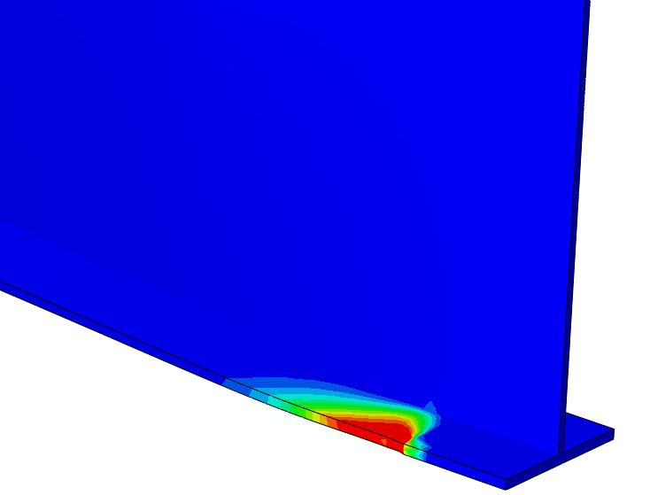
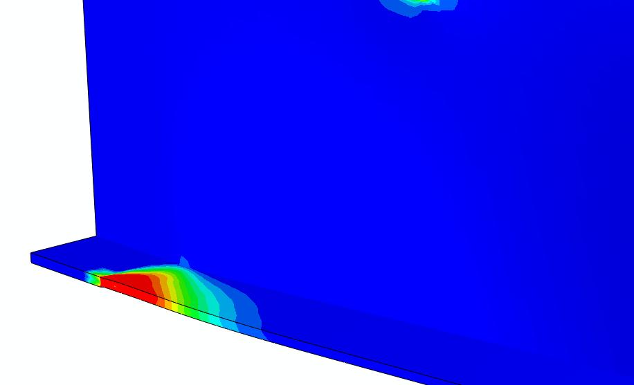
31 Displacement Magnitude OMAE : Offshore Platform Fluid Structure Interaction (FSI) Simulation 47cm 17cm 31
32 Comparison of Deformation of Plate Girders with Filed Data 50 Displacement in x-direction (cm) Member A - Field Data Member A - Analysis Results Member B - Field Data Member B - Analysis Results Lentgh of plate girder (m) Length =0.0m Length = 12.0m 32
33 Conclusions OMAE : Offshore Platform Fluid Structure Interaction (FSI) Simulation A One-way coupled Fluid Structure Interaction was investigated for predicting permanent deformation on an offshore platform from a large wave incident during a storm. Results are comparable to the actual field measurements The deformation on plate girders can also be due to several wave impacts during the hurricane and the deformation magnitude of the plate girders will be superimposed due to these multiple impacts Results suggest that sufficiently accurate solution for the design of offshore platforms can be obtained with this methodology. 33
A study of Jumper FIV due to multiphase internal flow: understanding life-cycle fatigue. Alan Mueller & Oleg Voronkov
 A study of Jumper FIV due to multiphase internal flow: understanding life-cycle fatigue Alan Mueller & Oleg Voronkov Case description Main structural dimensions [1]: deformable jumper [2] in Mixture on
ME Optimization of a Frame
 ME 475 - Optimization of a Frame Analysis Problem Statement: The following problem will be analyzed using Abaqus. 4 7 7 5,000 N 5,000 N 0,000 N 6 6 4 3 5 5 4 4 3 3 Figure. Full frame geometry and loading
Tutorial: Hydrodynamics of Bubble Column Reactors
 Tutorial: Introduction The purpose of this tutorial is to provide guidelines and recommendations for solving a gas-liquid bubble column problem using the multiphase mixture model, including advice on solver
Design Optimization of a Weather Radar Antenna using Finite Element Analysis (FEA) and Computational Fluid Dynamics (CFD)
 and Computational Fluid Dynamics (CFD)") Design Optimization of a Weather Radar Antenna using Finite Element Analysis (FEA) and Computational Fluid Dynamics (CFD) Fernando Prevedello Regis Ataídes Nícolas Spogis Wagner Ortega Guedes Fabiano Armellini
Design Optimization of a Weather Radar Antenna using Finite Element Analysis (FEA) and Computational Fluid Dynamics (CFD) Fernando Prevedello Regis Ataídes Nícolas Spogis Wagner Ortega Guedes Fabiano Armellini
Coupling of STAR-CCM+ to Other Theoretical or Numerical Solutions. Milovan Perić
 Coupling of STAR-CCM+ to Other Theoretical or Numerical Solutions Milovan Perić Contents The need to couple STAR-CCM+ with other theoretical or numerical solutions Coupling approaches: surface and volume
Coupled Analysis of FSI
 Coupled Analysis of FSI Qin Yin Fan Oct. 11, 2008 Important Key Words Fluid Structure Interface = FSI Computational Fluid Dynamics = CFD Pressure Displacement Analysis = PDA Thermal Stress Analysis = TSA
Figure 2: Water Into Kerosene, Volume Fraction (Left) And Total Density Of Mixture (Right)
 And Total Density Of Mixture (Right)") Jared Bottlinger MAE598 Project 3 11/16/17 Task 1 a) Figure 1: Volume Fraction Of Water At 0.4s Task 1 b) Figure 2: Water Into Kerosene, Volume Fraction (Left) And Total Density Of Mixture (Right) Task
Jared Bottlinger MAE598 Project 3 11/16/17 Task 1 a) Figure 1: Volume Fraction Of Water At 0.4s Task 1 b) Figure 2: Water Into Kerosene, Volume Fraction (Left) And Total Density Of Mixture (Right) Task
midas NFX 2017R1 Release Note
 Total Solution for True Analysis-driven Design midas NFX 2017R1 Release Note 1 midas NFX R E L E A S E N O T E 2 0 1 7 R 1 Major Improvements Midas NFX is an integrated finite element analysis program
CDA Workshop Physical & Numerical Hydraulic Modelling. STAR-CCM+ Presentation
 CDA Workshop Physical & Numerical Hydraulic Modelling STAR-CCM+ Presentation ENGINEERING SIMULATION CFD FEA Mission Increase the competitiveness of companies through optimization of their product development
Problem description. The FCBI-C element is used in the fluid part of the model.
 Problem description This tutorial illustrates the use of ADINA for analyzing the fluid-structure interaction (FSI) behavior of a flexible splitter behind a 2D cylinder and the surrounding fluid in a channel.
CFD MODELING FOR PNEUMATIC CONVEYING
 CFD MODELING FOR PNEUMATIC CONVEYING Arvind Kumar 1, D.R. Kaushal 2, Navneet Kumar 3 1 Associate Professor YMCAUST, Faridabad 2 Associate Professor, IIT, Delhi 3 Research Scholar IIT, Delhi e-mail: arvindeem@yahoo.co.in
2-D Tank Sloshing Using the Coupled Eulerian- LaGrangian (CEL) Capability of Abaqus/Explicit
 Capability of Abaqus/Explicit") 2-D Tank Sloshing Using the Coupled Eulerian- LaGrangian (CEL) Capability of Abaqus/Explicit Jeff D. Tippmann, Sharat C. Prasad 2, and Parthiv N. Shah ATA Engineering, Inc. San Diego, CA 923 2 Dassault
2-D Tank Sloshing Using the Coupled Eulerian- LaGrangian (CEL) Capability of Abaqus/Explicit Jeff D. Tippmann, Sharat C. Prasad 2, and Parthiv N. Shah ATA Engineering, Inc. San Diego, CA 923 2 Dassault
Calculate a solution using the pressure-based coupled solver.
 Tutorial 19. Modeling Cavitation Introduction This tutorial examines the pressure-driven cavitating flow of water through a sharpedged orifice. This is a typical configuration in fuel injectors, and brings
THE EFFECTS OF THE PLANFORM SHAPE ON DRAG POLAR CURVES OF WINGS: FLUID-STRUCTURE INTERACTION ANALYSES RESULTS
 March 18-20, 2013 THE EFFECTS OF THE PLANFORM SHAPE ON DRAG POLAR CURVES OF WINGS: FLUID-STRUCTURE INTERACTION ANALYSES RESULTS Authors: M.R. Chiarelli, M. Ciabattari, M. Cagnoni, G. Lombardi Speaker:
Fluid-Structure Interaction in STAR-CCM+ Alan Mueller CD-adapco
 Fluid-Structure Interaction in STAR-CCM+ Alan Mueller CD-adapco What is FSI? Air Interaction with a Flexible Structure What is FSI? Water/Air Interaction with a Structure Courtesy CFD Marine Courtesy Germanischer
Aero-Vibro Acoustics For Wind Noise Application. David Roche and Ashok Khondge ANSYS, Inc.
 Aero-Vibro Acoustics For Wind Noise Application David Roche and Ashok Khondge ANSYS, Inc. Outline 1. Wind Noise 2. Problem Description 3. Simulation Methodology 4. Results 5. Summary Thursday, October
ME 475 FEA of a Composite Panel
 ME 475 FEA of a Composite Panel Objectives: To determine the deflection and stress state of a composite panel subjected to asymmetric loading. Introduction: Composite laminates are composed of thin layers
Use 6DOF solver to calculate motion of the moving body. Create TIFF files for graphic visualization of the solution.
 Introduction The purpose of this tutorial is to provide guidelines and recommendations for setting up and solving a moving deforming mesh (MDM) case along with the six degree of freedom (6DOF) solver and
CFD modelling of thickened tailings Final project report
 26.11.2018 RESEM Remote sensing supporting surveillance and operation of mines CFD modelling of thickened tailings Final project report Lic.Sc.(Tech.) Reeta Tolonen and Docent Esa Muurinen University of
Optimization of under-relaxation factors. and Courant numbers for the simulation of. sloshing in the oil pan of an automobile
 Optimization of under-relaxation factors and Courant numbers for the simulation of sloshing in the oil pan of an automobile Swathi Satish*, Mani Prithiviraj and Sridhar Hari⁰ *National Institute of Technology,
Hydro-elastic analysis of a propeller using CFD and FEM co-simulation
 Fifth International Symposium on Marine Propulsors smp 17, Espoo, Finland, June 2017 Hydro-elastic analysis of a propeller using CFD and FEM co-simulation Vesa Nieminen 1 1 VTT Technical Research Centre
APPLIED COMPUTATIONAL FLUID DYNAMICS-PROJECT-3
 APPLIED COMPUTATIONAL FLUID DYNAMICS-PROJECT-3 BY SAI CHAITANYA MANGAVELLI Common Setup Data: 1) Mesh Proximity and Curvature with Refinement of 2. 2) Double Precision and second order for methods in Solver.
Wall thickness= Inlet: Prescribed mass flux. All lengths in meters kg/m, E Pa, 0.3,
 Problem description Problem 30: Analysis of fluid-structure interaction within a pipe constriction It is desired to analyze the flow and structural response within the following pipe constriction: 1 1
WAVE PATTERNS, WAVE INDUCED FORCES AND MOMENTS FOR A GRAVITY BASED STRUCTURE PREDICTED USING CFD
 Proceedings of the ASME 2011 30th International Conference on Ocean, Offshore and Arctic Engineering OMAE2011 June 19-24, 2011, Rotterdam, The Netherlands OMAE2011-49593 WAVE PATTERNS, WAVE INDUCED FORCES
Tutorial 17. Using the Mixture and Eulerian Multiphase Models
 Tutorial 17. Using the Mixture and Eulerian Multiphase Models Introduction: This tutorial examines the flow of water and air in a tee junction. First you will solve the problem using the less computationally-intensive
THE APPLICATION OF AN ATMOSPHERIC BOUNDARY LAYER TO EVALUATE TRUCK AERODYNAMICS IN CFD
 THE APPLICATION OF AN ATMOSPHERIC BOUNDARY LAYER TO EVALUATE TRUCK AERODYNAMICS IN CFD A SOLUTION FOR A REAL-WORLD ENGINEERING PROBLEM Ir. Niek van Dijk DAF Trucks N.V. CONTENTS Scope & Background Theory:
Simulation of Turbulent Flow over the Ahmed Body
 Simulation of Turbulent Flow over the Ahmed Body 58:160 Intermediate Mechanics of Fluids CFD LAB 4 By Timur K. Dogan, Michael Conger, Maysam Mousaviraad, and Fred Stern IIHR-Hydroscience & Engineering
EXPERIMENTAL VALIDATION OF STAR-CCM+ FOR LIQUID CONTAINER SLOSH DYNAMICS
 EXPERIMENTAL VALIDATION OF STAR-CCM+ FOR LIQUID CONTAINER SLOSH DYNAMICS Brandon Marsell a.i. solutions, Launch Services Program, Kennedy Space Center, FL 1 Agenda Introduction Problem Background Experiment
2008 International ANSYS Conference
 2008 International ANSYS Conference FEM AND FSI SIMULATIONS OF IMPACT LOADS ON GRP SUBSEA COMPOSITE COVERS Kjetil Rognlien, MSc Technical Consultant EDR AS, Norway 2008 ANSYS, Inc. All rights reserved.
ALE and Fluid-Structure Interaction in LS-DYNA March 2004
 ALE and Fluid-Structure Interaction in LS-DYNA March 2004 Workshop Models 1. Taylor bar impact 2. One-dimensional advection test 3. Channel 4. Underwater explosion 5. Bar impacting water surface 6. Sloshing
CFD VALIDATION FOR SURFACE COMBATANT 5415 STRAIGHT AHEAD AND STATIC DRIFT 20 DEGREE CONDITIONS USING STAR CCM+
 CFD VALIDATION FOR SURFACE COMBATANT 5415 STRAIGHT AHEAD AND STATIC DRIFT 20 DEGREE CONDITIONS USING STAR CCM+ by G. J. Grigoropoulos and I..S. Kefallinou 1. Introduction and setup 1. 1 Introduction The
Analysis Comparison between CFD and FEA of an Idealized Concept V- Hull Floor Configuration in Two Dimensions
 2010 NDIA GROUND VEHICLE SYSTEMS ENGINEERING AND TECHNOLOGY SYMPOSIUM MODELING & SIMULATION, TESTING AND VALIDATION (MSTV) MINI-SYMPOSIUM AUGUST 17-19 DEARBORN, MICHIGAN Analysis Comparison between CFD
Simulation of a Free Surface Flow over a Container Vessel Using CFD
 Simulation of a Free Surface Flow over a Container Vessel Using CFD Krishna Atreyapurapu 1 Bhanuprakash Tallapragada 2 Kiran Voonna 3 M.E Student Professor Manager Dept. of Marine Engineering Dept. of
3D Finite Element Software for Cracks. Version 3.2. Benchmarks and Validation
 3D Finite Element Software for Cracks Version 3.2 Benchmarks and Validation October 217 1965 57 th Court North, Suite 1 Boulder, CO 831 Main: (33) 415-1475 www.questintegrity.com http://www.questintegrity.com/software-products/feacrack
Milovan Perić CD-adapco. Use of STAR-CCM+ in Marine and Offshore Engineering and Future Trends
 Milovan Perić CD-adapco Use of STAR-CCM+ in Marine and Offshore Engineering and Future Trends Introduction CD-adapco is developing simulation capabilities in STAR-CCM+ specifically for marine and offshore
Project #3 MAE 598 Applied CFD
 Project #3 MAE 598 Applied CFD 16 November 2017 H.P. Huang 1 Task 1 (a) Task 1a was to perform a transient analysis of a 2-D chamber that is initially filled with air, and has water flowing through the
2008 International ANSYS Conference
 2008 International ANSYS Conference Simulation of Added Mass Effect on Disc Vibrating in Fluid Using Fluid-Structure Interaction Coupling of ANSYS/CFX QIAN LIKE ANSYS Japan K.K. 2008 ANSYS, Inc. All rights
COMPUTER AIDED ENGINEERING. Part-1
 COMPUTER AIDED ENGINEERING Course no. 7962 Finite Element Modelling and Simulation Finite Element Modelling and Simulation Part-1 Modeling & Simulation System A system exists and operates in time and space.
DNV GL s 16th Technology Week
 OIL & GAS DNV GL s 16th Technology Week Advanced Simulation for Offshore Application: Application of CFD for Computing VIM of Floating Structures 1 SAFER, SMARTER, GREENER OUTLINE Introduction Elements
Design Verification Procedure (DVP) Load Case Analysis of Car Bonnet
 Load Case Analysis of Car Bonnet") Design Verification Procedure (DVP) Load Case Analysis of Car Bonnet Mahesha J 1, Prashanth A S 2 M.Tech Student, Machine Design, Dr. A.I.T, Bangalore, India 1 Asst. Professor, Department of Mechanical
Design Verification Procedure (DVP) Load Case Analysis of Car Bonnet Mahesha J 1, Prashanth A S 2 M.Tech Student, Machine Design, Dr. A.I.T, Bangalore, India 1 Asst. Professor, Department of Mechanical
 Set No. 1 IV B.Tech. I Semester Regular Examinations, November 2010 FINITE ELEMENT METHODS (Mechanical Engineering) Time: 3 Hours Max Marks: 80 Answer any FIVE Questions All Questions carry equal marks
Analysis of Fluid-Structure Interaction Effects of Liquid-Filled Container under Drop Testing
 Kasetsart J. (Nat. Sci.) 42 : 165-176 (2008) Analysis of Fluid-Structure Interaction Effects of Liquid-Filled Container under Drop Testing Chakrit Suvanjumrat*, Tumrong Puttapitukporn and Satjarthip Thusneyapan
Use of STAR-CCM+ in Marine and Off-Shore Engineering - Key Features and Future Developments - M. Perić, F. Schäfer, E. Schreck & J.
 Use of STAR-CCM+ in Marine and Off-Shore Engineering - Key Features and Future Developments - M. Perić, F. Schäfer, E. Schreck & J. Singh Contents Main features of STAR-CCM+ relevant for marine and offshore
Air Assisted Atomization in Spiral Type Nozzles
 ILASS Americas, 25 th Annual Conference on Liquid Atomization and Spray Systems, Pittsburgh, PA, May 2013 Air Assisted Atomization in Spiral Type Nozzles W. Kalata *, K. J. Brown, and R. J. Schick Spray
Global to Local Model Interface for Deepwater Top Tension Risers
 Global to Local Model Interface for Deepwater Top Tension Risers Mateusz Podskarbi Karan Kakar 2H Offshore Inc, Houston, TX Abstract The water depths from which oil and gas are being produced are reaching
COMPUTATIONAL FLUID DYNAMICS ANALYSIS OF ORIFICE PLATE METERING SITUATIONS UNDER ABNORMAL CONFIGURATIONS
 COMPUTATIONAL FLUID DYNAMICS ANALYSIS OF ORIFICE PLATE METERING SITUATIONS UNDER ABNORMAL CONFIGURATIONS Dr W. Malalasekera Version 3.0 August 2013 1 COMPUTATIONAL FLUID DYNAMICS ANALYSIS OF ORIFICE PLATE
Tutorial: Simulating a 3D Check Valve Using Dynamic Mesh 6DOF Model And Diffusion Smoothing
 Tutorial: Simulating a 3D Check Valve Using Dynamic Mesh 6DOF Model And Diffusion Smoothing Introduction The purpose of this tutorial is to demonstrate how to simulate a ball check valve with small displacement
Drop-Test FSI simulation with Abaqus and FlowVision based on the direct 2-way coupling approach
 Visit the SIMULIA Resource Center for more customer examples. Drop-Test FSI simulation with Abaqus and FlowVision based on the direct 2-way coupling approach A. Aksenov 1), D.Korenev 1), A. Shyshaeva 1),
Transition Flow and Aeroacoustic Analysis of NACA0018 Satish Kumar B, Fred Mendonç a, Ghuiyeon Kim, Hogeon Kim
 Transition Flow and Aeroacoustic Analysis of NACA0018 Satish Kumar B, Fred Mendonç a, Ghuiyeon Kim, Hogeon Kim Transition Flow and Aeroacoustic Analysis of NACA0018 Satish Kumar B, Fred Mendonç a, Ghuiyeon
Chapter 3 Analysis of Original Steel Post
 Chapter 3. Analysis of original steel post 35 Chapter 3 Analysis of Original Steel Post This type of post is a real functioning structure. It is in service throughout the rail network of Spain as part
Exercise 1. 3-Point Bending Using the Static Structural Module of. Ansys Workbench 14.0
 Exercise 1 3-Point Bending Using the Static Structural Module of Contents Ansys Workbench 14.0 Learn how to...1 Given...2 Questions...2 Taking advantage of symmetries...2 A. Getting started...3 A.1 Choose
CHAPTER 1. Introduction
 ME 475: Computer-Aided Design of Structures 1-1 CHAPTER 1 Introduction 1.1 Analysis versus Design 1.2 Basic Steps in Analysis 1.3 What is the Finite Element Method? 1.4 Geometrical Representation, Discretization
ME Optimization of a Truss
 ME 475 - Optimization of a Truss Analysis Problem Statement: The following problem will be analyzed using Abaqus and optimized using HEEDS. 4 5 8 2 11 3 10 6 9 1 7 12 6 m 300 kn 300 kn 22 m 35 m Figure
Advances in Simulation for Marine And Offshore Applications. Milovan Perić
 Advances in Simulation for Marine And Offshore Applications Milovan Perić Introduction Extensions and enhancements in STAR-CCM+ for marine and offshore applications: Creation of irregular long-crested
Comparison Between Numerical & PIV Experimental Results for Gas-Solid Flow in Ducts
 Fabio Kasper Comparison Between Numerical & PIV Experimental Results for Gas-Solid Flow in Ducts Rodrigo Decker, Oscar Sgrott Jr., Henry F. Meier Waldir Martignoni Agenda Introduction The Test Bench Case
TABLE OF CONTENTS SECTION 2 BACKGROUND AND LITERATURE REVIEW... 3 SECTION 3 WAVE REFLECTION AND TRANSMISSION IN RODS Introduction...
 TABLE OF CONTENTS SECTION 1 INTRODUCTION... 1 1.1 Introduction... 1 1.2 Objectives... 1 1.3 Report organization... 2 SECTION 2 BACKGROUND AND LITERATURE REVIEW... 3 2.1 Introduction... 3 2.2 Wave propagation
CHAPTER-10 DYNAMIC SIMULATION USING LS-DYNA
 DYNAMIC SIMULATION USING LS-DYNA CHAPTER-10 10.1 Introduction In the past few decades, the Finite Element Method (FEM) has been developed into a key indispensable technology in the modeling and simulation
Exercise 1. 3-Point Bending Using the GUI and the Bottom-up-Method
 Exercise 1 3-Point Bending Using the GUI and the Bottom-up-Method Contents Learn how to... 1 Given... 2 Questions... 2 Taking advantage of symmetries... 2 A. Preprocessor (Setting up the Model)... 3 A.1
Applications of ICFD solver by LS-DYNA in Automotive Fields to Solve Fluid-Solid-Interaction (FSI) Problems
 Problems") Applications of ICFD solver by LS-DYNA in Automotive Fields to Solve Fluid-Solid-Interaction (FSI) Problems George Wang(1 ), Facundo del Pin(2), Inaki Caldichoury (2), Prince Rodriguez(3), Jason Tippie
Applications of ICFD solver by LS-DYNA in Automotive Fields to Solve Fluid-Solid-Interaction (FSI) Problems George Wang(1 ), Facundo del Pin(2), Inaki Caldichoury (2), Prince Rodriguez(3), Jason Tippie
Modeling Submerged Structures Loaded by Underwater Explosions with ABAQUS/Explicit
 Modeling Submerged Structures Loaded by Underwater Explosions with ABAQUS/Explicit David B. Woyak ABAQUS Solutions Northeast, LLC Abstract: Finite element analysis can be used to predict the transient
Terrain settlement analysis
 Engineering manual No. 21 Updated: 02/2018 Terrain settlement analysis Program: File: FEM Demo_manual_21.gmk This example contains the solution to terrain settlement under surcharge loading using the Finite
Quarter Symmetry Tank Stress (Draft 4 Oct 24 06)
") Quarter Symmetry Tank Stress (Draft 4 Oct 24 06) Introduction You need to carry out the stress analysis of an outdoor water tank. Since it has quarter symmetry you start by building only one-fourth of
Quarter Symmetry Tank Stress (Draft 4 Oct 24 06) Introduction You need to carry out the stress analysis of an outdoor water tank. Since it has quarter symmetry you start by building only one-fourth of
Three-Dimensional Verification Model of Floating Wind Energy Converter Using LS-DYNA3D Code
 American Scientific Research Journal for Engineering, Technology, and Sciences (ASRJETS) ISSN (Print) 2313-4410, ISSN (Online) 2313-4402 Global Society of Scientific Research and Researchers http://asrjetsjournal.org/
Tutorial: Riser Simulation Using Dense Discrete Phase Model
 Introduction The purpose of this tutorial is to demonstrate the setup of a dense discrete phase model (DDPM) with the example of 2D riser. DDPM is used for the secondary phase that has a particle size
Coupled Simulation of Flow and Body Motion Using Overset Grids. Eberhard Schreck & Milovan Perić
 Coupled Simulation of Flow and Body Motion Using Overset Grids Eberhard Schreck & Milovan Perić Contents Dynamic Fluid-Body Interaction (DFBI) model in STAR-CCM+ Overset grids method in STAR-CCM+ Advantages
Using the Eulerian Multiphase Model for Granular Flow
 Tutorial 21. Using the Eulerian Multiphase Model for Granular Flow Introduction Mixing tanks are used to maintain solid particles or droplets of heavy fluids in suspension. Mixing may be required to enhance
Analysis of fluid-solid coupling vibration characteristics of probe based on ANSYS Workbench
 Analysis of fluid-solid coupling vibration characteristics of probe based on ANSYS Workbench He Wang 1, a, Changzheng Zhao 1, b and Hongzhi Chen 1, c 1 Shandong University of Science and Technology, Qingdao
Simulating Sinkage & Trim for Planing Boat Hulls. A Fluent Dynamic Mesh 6DOF Tutorial
 Simulating Sinkage & Trim for Planing Boat Hulls A Fluent Dynamic Mesh 6DOF Tutorial 1 Introduction Workshop Description This workshop describes how to perform a transient 2DOF simulation of a planing
Workshop 15. Single Pass Rolling of a Thick Plate
 Introduction Workshop 15 Single Pass Rolling of a Thick Plate Rolling is a basic manufacturing technique used to transform preformed shapes into a form suitable for further processing. The rolling process
Exercise 2: Mesh Resolution, Element Shapes, Basis Functions & Convergence Analyses
 Exercise 2: Mesh Resolution, Element Shapes, Basis Functions & Convergence Analyses Goals In this exercise, we will explore the strengths and weaknesses of different element types (tetrahedrons vs. hexahedrons,
Development of an Integrated Computational Simulation Method for Fluid Driven Structure Movement and Acoustics
 Development of an Integrated Computational Simulation Method for Fluid Driven Structure Movement and Acoustics I. Pantle Fachgebiet Strömungsmaschinen Karlsruher Institut für Technologie KIT Motivation
Module 1: Introduction to Finite Element Analysis. Lecture 4: Steps in Finite Element Analysis
 25 Module 1: Introduction to Finite Element Analysis Lecture 4: Steps in Finite Element Analysis 1.4.1 Loading Conditions There are multiple loading conditions which may be applied to a system. The load
ANSYS Element. elearning. Peter Barrett October CAE Associates Inc. and ANSYS Inc. All rights reserved.
 ANSYS Element Selection elearning Peter Barrett October 2012 2012 CAE Associates Inc. and ANSYS Inc. All rights reserved. ANSYS Element Selection What is the best element type(s) for my analysis? Best
Developing Tools for Assessing Bend-twist Coupled Foils
 Developing Tools for Assessing Bend-twist Coupled Foils Laura Marimon Giovannetti, Joseph Banks, Stephen R. Turnock, Stephen W. Boyd, University of Southampton, Southampton/UK, L.Marimon-Giovannetti@soton.ac.uk
Engineering Analysis
 Engineering Analysis with SOLIDWORKS Simulation 2018 Paul M. Kurowski SDC PUBLICATIONS Better Textbooks. Lower Prices. www.sdcpublications.com Powered by TCPDF (www.tcpdf.org) Visit the following websites
Advances in Cyclonic Flow Regimes. Dr. Dimitrios Papoulias, Thomas Eppinger
 Advances in Cyclonic Flow Regimes Dr. Dimitrios Papoulias, Thomas Eppinger Agenda Introduction Cyclones & Hydrocyclones Modeling Approaches in STAR-CCM+ Turbulence Modeling Case 1: Air-Air Cyclone Case
Guidelines for proper use of Plate elements
 Guidelines for proper use of Plate elements In structural analysis using finite element method, the analysis model is created by dividing the entire structure into finite elements. This procedure is known
1.992, 2.993, 3.04, 10.94, , Introduction to Modeling and Simulation Prof. F.-J. Ulm Spring FE Modeling Example Using ADINA
 1.992, 2.993, 3.04, 10.94, 18.996, 22.091 Introduction to Modeling and Simulation Prof. F.-J. Ulm Spring 2002 FE Modeling Example Using ADINA H Hgρ w ργ H = B = 10 m g = 9.81 m/s 2 ρ = 2400 kg/m 3 ρ w
Aufgabe 1: Dreipunktbiegung mit ANSYS Workbench
 Aufgabe 1: Dreipunktbiegung mit ANSYS Workbench Contents Beam under 3-Pt Bending [Balken unter 3-Pkt-Biegung]... 2 Taking advantage of symmetries... 3 Starting and Configuring ANSYS Workbench... 4 A. Pre-Processing:
Recent Advances on Higher Order 27-node Hexahedral Element in LS-DYNA
 14 th International LS-DYNA Users Conference Session: Simulation Recent Advances on Higher Order 27-node Hexahedral Element in LS-DYNA Hailong Teng Livermore Software Technology Corp. Abstract This paper
Modelling Flat Spring Performance Using FEA
 Modelling Flat Spring Performance Using FEA Blessing O Fatola, Patrick Keogh and Ben Hicks Department of Mechanical Engineering, University of Corresponding author bf223@bath.ac.uk Abstract. This paper
CHAPTER 4. Numerical Models. descriptions of the boundary conditions, element types, validation, and the force
 CHAPTER 4 Numerical Models This chapter presents the development of numerical models for sandwich beams/plates subjected to four-point bending and the hydromat test system. Detailed descriptions of the
Gear interlocking effect study using CFD
 Gear interlocking effect study using CFD Peyman Jafarian M.Sc. Simulation Engineer Vicura AB, Sweden ABSTRACT Estimating the drag loss and predicting the oil flow distribution within the transmission has
Development of the Compliant Mooring Line Model for FLOW-3D
 Flow Science Report 08-15 Development of the Compliant Mooring Line Model for FLOW-3D Gengsheng Wei Flow Science, Inc. October 2015 1. Introduction Mooring systems are common in offshore structures, ship
NUMERICAL STUDY OF CAVITATING FLOW INSIDE A FLUSH VALVE
 Conference on Modelling Fluid Flow (CMFF 09) The 14th International Conference on Fluid Flow Technologies Budapest, Hungary, September 9-12, 2009 NUMERICAL STUDY OF CAVITATING FLOW INSIDE A FLUSH VALVE
Verification and Validation for Seismic Wave Propagation Problems
 Chapter 26 Verification and Validation for Seismic Wave Propagation Problems (1989-2-24-25-28-29-21-211-217-) (In collaboration with Dr. Nima Tafazzoli, Dr. Federico Pisanò, Mr. Kohei Watanabe and Mr.
CHAPTER 4 CFD AND FEA ANALYSIS OF DEEP DRAWING PROCESS
 54 CHAPTER 4 CFD AND FEA ANALYSIS OF DEEP DRAWING PROCESS 4.1 INTRODUCTION In Fluid assisted deep drawing process the punch moves in the fluid chamber, the pressure is generated in the fluid. This fluid
Chapter 5 Modeling and Simulation of Mechanism
 Chapter 5 Modeling and Simulation of Mechanism In the present study, KED analysis of four bar planar mechanism using MATLAB program and ANSYS software has been carried out. The analysis has also been carried
Introduction to 2 nd -order Lagrangian Element in LS-DYNA
 Introduction to 2 nd -order Lagrangian Element in LS-DYNA Hailong Teng Livermore Software Technology Corporation Nov, 2017 Motivation Users are requesting higher order elements for implicit. Replace shells.
2: Static analysis of a plate
 2: Static analysis of a plate Topics covered Project description Using SolidWorks Simulation interface Linear static analysis with solid elements Finding reaction forces Controlling discretization errors
Simulation of AJWSP10033_FOLDED _ST_FR
 Phone: 01922 453038 www.hyperon-simulation-and-cad-services.co.uk Simulation of AJWSP10033_FOLDED _ST_FR Date: 06 May 2017 Designer: Study name: AJWSP10033_FOLDED_STATIC Analysis type: Static Description
CFD Simulation for Stratified Oil-Water Two-Phase Flow in a Horizontal Pipe
 CFD Simulation for Stratified Oil-Water Two-Phase Flow in a Horizontal Pipe Adib Zulhilmi Mohd Alias, a, Jaswar Koto, a,b,* and Yasser Mohamed Ahmed, a a) Department of Aeronautics, Automotive and Ocean
Revised Sheet Metal Simulation, J.E. Akin, Rice University
 Revised Sheet Metal Simulation, J.E. Akin, Rice University A SolidWorks simulation tutorial is just intended to illustrate where to find various icons that you would need in a real engineering analysis.
MASSACHUSETTS INSTITUTE OF TECHNOLOGY. Analyzing wind flow around the square plate using ADINA Project. Ankur Bajoria
 MASSACHUSETTS INSTITUTE OF TECHNOLOGY Analyzing wind flow around the square plate using ADINA 2.094 - Project Ankur Bajoria May 1, 2008 Acknowledgement I would like to thank ADINA R & D, Inc for the full
2D numerical simulation of ocean waves
 2D numerical simulation of ocean waves Qingjie. Du,*, Y.C. Dennis. Leung Department of Mechanical Engineering, The University of Hong Kong, Hong Kong, China * Corresponding author. Tel: +852 51743593,
The second part of the tutorial continues with the subsequent ANSYS Mechanical simulation steps:
 Tutorial: Simulation of aero-vibro-acoustic phenomena using ANSYS Fluent and ANSYS Mechanical. Test case: Noise inside a cavity with a vibrating wall, caused by the external turbulent flow. Introduction
Fluid-structure Interaction by the mixed SPH-FE Method with Application to Aircraft Ditching
 Fluid-structure Interaction by the mixed SPH-FE Method with Application to Aircraft Ditching Paul Groenenboom ESI Group Delft, Netherlands Martin Siemann German Aerospace Center (DLR) Stuttgart, Germany
Validation of CFD Simulation with Scaled Physical Model of Tailings Dissipation Boxes
 Validation of CFD Simulation with Scaled Physical Model of Tailings Dissipation Boxes José Facusse Ingeniero Mecánico Daniel Manzo Ingeniero Hidráulico PRESENTATION TOPICS Company Overview; Problem Description;
Using three-dimensional CURVIC contact models to predict stress concentration effects in an axisymmetric model
 Boundary Elements XXVII 245 Using three-dimensional CURVIC contact models to predict stress concentration effects in an axisymmetric model J. J. Rencis & S. R. Pisani Department of Mechanical Engineering,
Difficulties in FE-modelling of an I- beam subjected to torsion, shear and bending
 DEGREE PROJECT, IN STEEL STRUCTURES, SECOND LEVEL STOCKHOLM, SWEDEN 2015 Difficulties in FE-modelling of an I- beam subjected to torsion, shear and bending MIRIAM ALEXANDROU KTH ROYAL INSTITUTE OF TECHNOLOGY