ROBOTSTUDIO LECTURES. Introduction to RobotStudio. What is RobotStudio? How to start it up Structured walk-through
|
|
|
- Aubrey Ramsey
- 5 years ago
- Views:
Transcription
1 ROBOTSTUDIO LECTURES Introduction to RobotStudio What is RobotStudio? How to start it up Structured walk-through
2 What is RobotStudio? RobotStudio is ABB's simulation and offline programming software It allows robot programming to be done on a PC in the office without shutting down production It also enables robot programs to be prepared in advance, increasing overall productivity RobotStudio provides tools to let you perform tasks such as training, programming, and optimization without disturbing production What is RobotStudio? RobotStudio is built on the ABB VirtualController, an exact copy of the real software that runs your robot in production It thus allows very realistic simulations to be performed, using real robot programs and configuration files identical to those used on the shop floor

3 What is RobotStudio? How to start up RobotStudio Click here to download RobotStudio You can run in Premium Mode for 30 days; it then reverts to Basic Mode Follow the installation instructions for RobotWare and RobotStudio Once installed, double-click on the desktop icon to start RobotStudio
4 Structured walk-through When you start up RobotStudio, by default you will be taken to a page where you can Create a new Station Click on Station with Robot Controller This will create a new, empty station You will be given a choice of robots to include in the station; RobotStudio will automatically incorporate a matching virtual controller Structured walk-through I usually pick the IRB140T 6kg 0.81m type C robot, but you may choose whichever you like (a smaller robot is better for these exercises though ) If given a choice of libraries, pick IRB140T_6_81_C_01 The robot will be inserted into an empty work cell

5 Structured walk-through Structured walk-through Examine the different toolbars Home Modeling Simulation Controller RAPID Add-Ins
6 Structured walk-through Navigation, etc. Ctrl + Click n Drag left mouse button to pan Ctrl + Click n Drag right mouse button to zoom Ctrl + scroll-wheel to zoom in or out (zoom is centered around the mouse pointer) Ctrl + Shift + Click n Drag left mouse button to rotate Structured walk-through Jog the robot joints Click on Jog Joint icon Click on a joint, then move the joint Linearly jog the tool Have choice of coordinate systems to use By default, the world coordinate is used Click on the tool mounting plate to select it Then click on the Jog Linear icon Click and drag the arrows to jog the tool
7 Structured walk-through Linearly jog the tool Note the tool mounting plate moves linearly w.r.t. the world coordinate system; the robot joints move as needed Click on the coordinate system dropdown box and select Active Tool Notice the coordinate system on the tool mounting plate changes Click and drag now on the arrows and the plate moves w.r.t. the local (tool) coordinate system Structured walk-through Add a training tool to the robot On the Home toolbar, click on the Import Library dropdown Select Equipment, then scroll down to Training Objects and select mytool The tool is added to the workcell, but is not attached to the robot yet (by default it s located at (0,0,0) in the world coordinate system in the middle of the robot base!)
8 Structured walk-through Add a training tool to the robot In the Layout tab in the pane at the left of the screen, right-click on MyTool Scroll down to Attach to and then click on the robot (there will only be one robot to select from at this point) A pop-up window will appear asking if you want to update the position of the tool answer Yes The tool will now be attached to the tool mounting plate on the end of the robot arm Structured walk-through Add a training tool to the robot Note that the coordinate system for the tool is different from that of the tool mounting plate this is perfectly acceptable If you now go back to the Jog Linear icon, notice that point where the coordinate systems appear (world, Active Tool, etc.) is at the tip of the tool
9 Structured walk-through Add a work piece to the workcell On the Home toolbar, click on the Import Library dropdown Select Equipment, then scroll down to Training Objects and select Curve Thing The object is added to the workcell; it ends up floating out in space in front of the robot (ABB is working on patenting anti-gravity ) Structured walk-through Drag the Curve Thing object closer to the robot Click on the object to select it Click on the Move icon Make sure the coordinate system dropdown says World Click and drag on the arrows to move the object Move the object so it is low and centered in front of the robot
10 Structured walk-through Reorient the Curve Thing object Notice that the object is rotated some w.r.t. the World coordinate system; let s get it lined up nicely Right-click on the object Scroll down to Set position and click on that The Set Position dialog box will appear in the lefthand pane; the reference coordinate system should, by default, be set to World Notice that the object has some non-zero rotation in the Y and Z axes Structured walk-through Reorient the Curve Thing object Note that we can also see the position of the origin of the object w.r.t. the World coordinate system Zero all of the angles and set the position to be (550, -170, 250) Click Apply and notice the object has been moved and reoriented Close the Set Position dialog box
11 Structured walk-through Create a path using AutoPath On the Home toolbar, click on the Path dropdown, then select AutoPath; this opens the AutoPath dialog box Pick the four top edges of the lower part of the Curve Thing object Note that as you click on them, path edges are added to the dialog box When all four edges have been added, then click on the Create button You can then close the dialog box Structured walk-through Create a path using AutoPath Note that a path has been created; by default it is called Path_10 Five targets have also been created; they are called Target_10, Target_20,, Target_50 Notice also that MoveL (move linear) instructions have been added to the path that reference the targets
12 ROBOTSTUDIO LECTURES Introduction to RobotStudio Adding targets and paths using AutoPath Setting up tool orientation Moving along a path

13 Here is the workcell after adding mytool and the Curve Thing Create a path using AutoPath On the Home toolbar, click on the Path dropdown, then select AutoPath; this opens the AutoPath dialog box Pick the four top edges of the lower part of the Curve Thing object Note that as you click on them, path edges are added to the dialog box When all four edges have been added, then click on the Create button You can then close the dialog box
14 You can see here the first path segment is being chosen Work your way around the surface to create a closed path Create a path using AutoPath Note that a path has been created; by default it is called Path_10 Five targets have also been created; they are called Target_10, Target_20,, Target_50 Notice also that MoveL (move linear) instructions have been added to the path that reference the targets

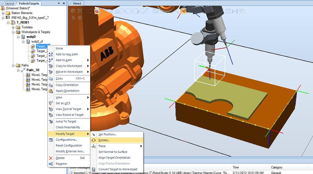
15 Right-click on Target_10 and then select View Tool at Target mytool This allows you to view the EOAT at the target without actually moving the robot The tool may not be in the orientation you desire
 In this case, a 90 rotation around the Z (blue) axis gets the tool oriented")
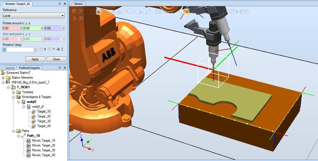
16 Right-click on Target_10 and then select Modify Target Rotate This allows you to rotate the target in various ways to adjust the tool orientation (which is tied to the target) In this case, a 90 rotation around the Z (blue) axis gets the tool oriented properly
17

18 If you click on the other targets, you will see that they too may not be oriented correctly You can copy the orientation from Target_10, and then apply that to the other targets Right-click on Target_10 and then select Copy Orientation Now select the other targets, then click on Apply Orientation Each of the targets will now have the same orienation

19 Before we go any further, let s make sure the robot can reach each of the targets with the selected tool orientation Right-click on Target_10 and then select View Robot at Target The robot and EOAT are moved according to the pose defined by the selected target

20 Test the other targets Notice that not all of the targets are reachable! Specifically, Target_30 and Target_40 are not able to be reached You will see warning messages to this effect
 closer to the")

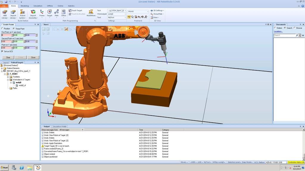
21 So let s move the workpiece (Curve Thing) closer to the robot Oh, oh! We moved the workpiece but the targets didn t move!
22 The targets are tied to the World coordinate system At this point the only thing we can do is to delete the targets and path and start over again Shortly we ll see a way to tie the targets to the workpiece so that as it moves we can move the targets along with it ROBOTSTUDIO LECTURES
23 Creating Workobjects Workobjects are how we are able to tie targets to a particular object Workobject 0 (wobj0) always exists it is tied to the World coordinate system To create a new workobject, one first creates a user coordinate system (UCS) Creating a User Coordinate System On the Home tab, click on the Frame icon Select Frame from Three Points This will open up a dialog box on the left side of the screen called Create Frame Select the Three Point radio button Then click in the red text box for First Point on X axis (mm)
24 Creating a User Coordinate System Creating a User Coordinate System


25 Creating a User Coordinate System Select the Snap Edge tool Now move the mouse along the near edge of the base of the Curve Thing You will see a ball snap to the nearest edge of the Curve Thing and track along that edge as you move the mouse Creating a User Coordinate System We intend to create a frame at the near left corner of the base of the Curve Thing, so click the mouse when the ball is near that corner It will replace the ball with a yellow asterisk and fill in the coordinates of the selected point as shown in the next picture
26 Creating a User Coordinate System Now select a point farther out along the same edge and click again The coordinates of this second point are filled in as the Second point on X axis (mm) Creating a User Coordinate System Now move along the perpendicular edge to the left (you can see the ball in the picture below) Now click again; this will select a point along the edge and define the XY plane of the frame This fills in the address of the third point in Point on Y axis (mm)

27 Creating a User Coordinate System Now click on Create in the dialog box to create the frame The origin of the frame will be where the last point forms the shortest perpendicular to the line formed by the first two points in this case at the corner of the supporting platform of the Curve Thing Creating a Workobject The next step is to turn the frame into a work object Go to the Layout tab in the left-hand pane, then right-click on the newly created frame, then select Convert Frame to Workobject
28 Creating a Workobject The frame disappears and is replaced by a workobject (Workobject_1 in this case) which you can see in the Paths&Targets tab Creating a Workobject You will notice that the newly created workobject is now set as the default
29 Now create the paths as you did in the previous exercise The difference in this case is that the targets are created with respect to the new workobject (Workobject_1) as opposed to the default workobject (wobj0) When you are done creating the path, go through the usual process of orienting the tool and setting up the target configurations Verify that the robot can move correctly along the path Re-orienting the work piece Once that is done, then go back to the Home tab and select the Layout tab in the left-hand pane Click on Curve_thing in the menu then go up to the toolbar and use the Move and Rotate tools to change the position and orientation of the work piece Don t get too carried away. If you move it too much the robot may no longer be able to reach!
30 Re-orienting the work piece Re-orienting the work piece Notice that the work object and the targets did not move along with the work piece We obviously want to be able to fix things up without having to recreate all of the targets, etc. We will use the fact that the targets were created relative to Workobject_1 to make this easy If we can correct the pose of Workobject_1 so it matches the newly oriented work piece, then all the targets will move accordingly

 Now go back to the view of the robot and again select the Snap Edge tool (just as you did earlier) Then click on two points along the same")
31 Correcting the pose of Workobject_1 Go to the Paths&Targets tab in the left-hand pane. Right-click on Workobject_1 then click on Modify Workobject The Modify Workobject dialog box will appear In the User Frame section of the dialog box, click on Frame by points and then click the down arrow to open another dialog box Correcting the pose of Workobject_1 Click on the Three-point radio button; then click in the red text box under First point on X axis (mm) Now go back to the view of the robot and again select the Snap Edge tool (just as you did earlier) Then click on two points along the same edge of the work piece as you did before (the X axis) and then click on a point along the Y axis

32 Correcting the pose of Workobject_1 Correcting the pose of Workobject_1 Go back to the dialog box and click Accept when you are done Then click Apply in the Modify Workobject dialog box

33 Correcting the pose of Workobject_1 Correcting the pose of Workobject_1 You should now see that the work object and targets have moved so that they are now realigned with the work piece Note that you will need to re-verify the configuration data for the targets The process for doing that is exactly the same as before
34 Correcting the pose of Workobject_1 There remains one thing to do which is to synchronize your code with the changes you have made to the station Click on the Synchronize to VC icon Select all of the items that appear in the popup dialog box and then click on OK You can now go back to the Robot tab; note that the robtarget values have been updated Run the program
Autodesk Inventor - Basics Tutorial Exercise 1
 Autodesk Inventor - Basics Tutorial Exercise 1 Launch Inventor Professional 2015 1. Start a New part. Depending on how Inventor was installed, using this icon may get you an Inch or Metric file. To be
KIN 147 Lab Practical Mid-term: Ground Reaction Force (GRF) Data Analysis
 Data Analysis") KIN 147 Lab Practical Mid-term: Ground Reaction Force (GRF) Data Analysis Excel analyses work much better on PCs than on Macs (especially older Macs) Your goal is to correctly analyze GRF data Analyzing
KIN 147 Lab Practical Mid-term: Ground Reaction Force (GRF) Data Analysis Excel analyses work much better on PCs than on Macs (especially older Macs) Your goal is to correctly analyze GRF data Analyzing
KIN 147 Lab 06: Ground Reaction Force (GRF) Data Analysis Excel analyses work much better on PCs than on Macs (especially older Macs)
 Data Analysis Excel analyses work much better on PCs than on Macs (especially older Macs)") KIN 147 Lab 06: Ground Reaction Force (GRF) Data Analysis Excel analyses work much better on PCs than on Macs (especially older Macs) Your goal is to correctly analyze GRF data Analyzing the GRF Data from
KIN 147 Lab 06: Ground Reaction Force (GRF) Data Analysis Excel analyses work much better on PCs than on Macs (especially older Macs) Your goal is to correctly analyze GRF data Analyzing the GRF Data from
KIN 147 Lab 02: Acceleration Data Analysis
 KIN 147 Lab 02: Acceleration Data Analysis Excel analyses work much better on PCs than on Macs (especially older Macs) Your goal is to correctly analyze accelerometer data Analyzing the Acceleration Data
introduction Manipulate objects and navigate in the 3Dworld Use the electronic catalogue (ecat) Change component parameters Connect components
 Change component parameters Connect components") Tutorials HVCG Conveyors HVCG Conveyor Tutorial /11 Related files HVCGConveyorTutorial.vcp Description The HVCGConveyorTutorial component package extracts the equipment models used in this tutorial. You
Tutorials HVCG Conveyors HVCG Conveyor Tutorial /11 Related files HVCGConveyorTutorial.vcp Description The HVCGConveyorTutorial component package extracts the equipment models used in this tutorial. You
SLAMWARE. RoboStudio. User Manual. Shanghai Slamtec.Co.,Ltd rev.1.1
 www.slamtec.com 2017-11-06 rev.1.1 SLAMWARE RoboStudio User Manual Shanghai Slamtec.Co.,Ltd Contents CONTENTS... 1 INTRODUCTION... 3 USER GUIDE... 4 OFFLINE/ONLINE MODE... 4 CONNECT/DISCONNECT ROBOT...
Chapter 4. Part 1 AutoCAD Basics
 Chapter 4. Part 1 AutoCAD Basics Chapter Objectives Describe the AutoCAD screen layout. Perform an AutoCAD drawing setup, including setting units, limits, layers, linetypes, and lineweights. Explain the
Creating a Text Frame. Create a Table and Type Text. Pointer Tool Text Tool Table Tool Word Art Tool
 Pointer Tool Text Tool Table Tool Word Art Tool Picture Tool Clipart Tool Creating a Text Frame Select the Text Tool with the Pointer Tool. Position the mouse pointer where you want one corner of the text
User Interface Guide
 User Interface Guide 1 Contents Overview... 3 Tabmenu... 4 Design modes... 4 Tool groups... 5 Design function groups... 5 Main menu... 6 Toolbars... 7 Drawing area... 9 Status bar... 11 Coordinate box...
This lesson introduces Blender, covering the tools and concepts necessary to set up a minimal scene in virtual 3D space.
 3D Modeling with Blender: 01. Blender Basics Overview This lesson introduces Blender, covering the tools and concepts necessary to set up a minimal scene in virtual 3D space. Concepts Covered Blender s
2D Tutorial. Project Description: Running VisualAnalysis: Setting Up the Project:
 2D Tutorial Project Description: This project has been set-up to demonstrate the basic features of VisualAnalysis. You will model and analyze the following two-dimensional frame with a curved glue-laminated
Exercise 2a: Load, Animate and Review a Model
 Exercise 2a: Load, Animate and Review a Model This exercise uses the file bumper_deck.key and the corresponding d3plot. Step 1: Load the solver input and result files, bumper_deck.key and d3plot. 1. From
KIN 147 Lab Practical Mid-term: Tibial Acceleration Data Analysis Excel analyses work much better on PCs than on Macs (especially older Macs)
") KIN 147 Lab Practical Mid-term: Tibial Acceleration Data Analysis Excel analyses work much better on PCs than on Macs (especially older Macs) Your goal is to correctly analyze accelerometer data Analyzing
KIN 147 Lab Practical Mid-term: Tibial Acceleration Data Analysis Excel analyses work much better on PCs than on Macs (especially older Macs) Your goal is to correctly analyze accelerometer data Analyzing
Introduction And Overview ANSYS, Inc. All rights reserved. 1 ANSYS, Inc. Proprietary
 Introduction And Overview 2006 ANSYS, Inc. All rights reserved. 1 ANSYS, Inc. Proprietary The ANSYS Workbench represents more than a general purpose engineering tool. It provides a highly integrated engineering
Excel 2013 Intermediate
 Instructor s Excel 2013 Tutorial 2 - Charts Excel 2013 Intermediate 103-124 Unit 2 - Charts Quick Links Chart Concepts Page EX197 EX199 EX200 Selecting Source Data Pages EX198 EX234 EX237 Creating a Chart
Introduction to Mercury
 Introduction to Mercury The Cambridge Crystallographic Data Centre (CCDC) distributes Mercury, which is a program that can be used to view and analyze crystal structure data. We will be using it over the
Troubleshooting in Microsoft Excel 2002
 Page 1 of 8 Troubleshooting in Microsoft Excel 2002 Result: To understand how to work with the Excel software to enter data, navigate the page, and print materials. Tabs Look at the tabs at the bottom
Objective. steps. Tutorials Robot Programming External TCP
 Tutorials Robot Programming External TCP External TCP 1/6 Related files ExternalTCP.vcp Description Component package that contains some ready made components to aid in the External TCP tutorial. Objective
3D Design with 123D Design
 3D Design with 123D Design Introduction: 3D Design involves thinking and creating in 3 dimensions. x, y and z axis Working with 123D Design 123D Design is a 3D design software package from Autodesk. A
RobotStudio 6.06 News. Henrik Berlin, Program Manager
 RobotStudio 6.06 News Henrik Berlin, Program Manager Content Simulation Material transport based on physics simulation Spray paint visualization Offline programming Geometric modeling Integrated vision
Start AxisVM by double-clicking the AxisVM icon in the AxisVM folder, found on the Desktop, or in the Start, Programs Menu.
 1. BEAM MODEL Start New Start AxisVM by double-clicking the AxisVM icon in the AxisVM folder, found on the Desktop, or in the Start, Programs Menu. Create a new model with the New Icon. In the dialogue
Adobe Flash CS4 Part 4: Interactivity
 CALIFORNIA STATE UNIVERSITY, LOS ANGELES INFORMATION TECHNOLOGY SERVICES Adobe Flash CS4 Part 4: Interactivity Fall 2010, Version 1.0 Table of Contents Introduction... 2 Downloading the Data Files... 2
SketchUp Tool Basics
 SketchUp Tool Basics Open SketchUp Click the Start Button Click All Programs Open SketchUp Scroll Down to the SketchUp 2013 folder Click on the folder to open. Click on SketchUp. Set Up SketchUp (look
How to...create a Video VBOX Gauge in Inkscape. So you want to create your own gauge? How about a transparent background for those text elements?
 BASIC GAUGE CREATION The Video VBox setup software is capable of using many different image formats for gauge backgrounds, static images, or logos, including Bitmaps, JPEGs, or PNG s. When the software
1. Move your mouse to the location you wish text to appear in the document. 2. Click the mouse. The insertion point appears.
 Word 2010 Text Basics Introduction Page 1 It is important to know how to perform basic tasks with text when working in a word processing application. In this lesson you will learn the basics of working
Using Microsoft Word. Text Editing
 Using Microsoft Word A word processor is all about working with large amounts of text, so learning the basics of text editing is essential to being able to make the most of the program. The first thing
SOLIDWORKS: Lesson 1 - Basics and Modeling. Introduction to Robotics
 SOLIDWORKS: Lesson 1 - Basics and Modeling Fundamentals Introduction to Robotics SolidWorks SolidWorks is a 3D solid modeling package which allows users to develop full solid models in a simulated environment
4. In the Change Chart Type dialog box, click the type of chart to which you want to change. 5. Click the chart style. 6. Click OK.
 PROCEDURES LESSON 21: BUILDING BASIC CHARTS Creating a Chart 1 Select the range of data you want to chart 2 Click the INSERT tab Charts Group 3 Click the desired chart category button 4 In the gallery,
DW DIGs Model Windows Tricks
 Window Menu 1. Window > Cascade Windows All open windows that aren't minimized at the bottom of the screen will be offset diagonally so you can see the title bar of each. 2. Window > Tile Windows All open
Using Adobe Photoshop
 Using Adobe Photoshop 2 In this section we ll look at some essential things you need to know in order to use Photoshop effectively. First of all, we ll take a look at customising Photoshop s settings and
EASI MP-X Series. User Manual EASI MPR. Workstation. MPR Workstation user manual, , rev003
 EASI MP-X Series User Manual EASI MPR Workstation MPR Workstation user manual, 59300234, rev003 Contents MPR Workstation Introduction...1 General...1 Software version...1 Structure of the Network...1 Workstation
XnView 1.9. a ZOOMERS guide. Introduction...2 Browser Mode... 5 Image View Mode...15 Printing Image Editing...28 Configuration...
 XnView 1.9 a ZOOMERS guide Introduction...2 Browser Mode... 5 Image View Mode...15 Printing... 22 Image Editing...28 Configuration... 36 Written by Chorlton Workshop for hsbp Introduction This is a guide
Profile Modeler Profile Modeler ( A SuperControl Product )
") Profile Modeler ( A SuperControl Product ) - 1 - Index Overview... 3 Terminology... 3 Launching the Application... 4 File Menu... 4 Loading a File:... 4 To Load Multiple Files:... 4 Clearing Loaded Files:...
Profile Modeler ( A SuperControl Product ) - 1 - Index Overview... 3 Terminology... 3 Launching the Application... 4 File Menu... 4 Loading a File:... 4 To Load Multiple Files:... 4 Clearing Loaded Files:...
SolidWorks Intro Part 1b
 SolidWorks Intro Part 1b Dave Touretzky and Susan Finger 1. Create a new part We ll create a CAD model of the 2 ½ D key fob below to make on the laser cutter. Select File New Templates IPSpart If the SolidWorks
Premiere Pro Desktop Layout (NeaseTV 2015 Layout)
") Premiere Pro 2015 1. Contextually Sensitive Windows - Must be on the correct window in order to do some tasks 2. Contextually Sensitive Menus 3. 1 zillion ways to do something. No 2 people will do everything
Premiere Pro 2015 1. Contextually Sensitive Windows - Must be on the correct window in order to do some tasks 2. Contextually Sensitive Menus 3. 1 zillion ways to do something. No 2 people will do everything
Exercise Guide. Published: August MecSoft Corpotation
 VisualCAD Exercise Guide Published: August 2018 MecSoft Corpotation Copyright 1998-2018 VisualCAD 2018 Exercise Guide by Mecsoft Corporation User Notes: Contents 2 Table of Contents About this Guide 4
Autodesk Inventor Design Exercise 2: F1 Team Challenge Car Developed by Tim Varner Synergis Technologies
 Autodesk Inventor Design Exercise 2: F1 Team Challenge Car Developed by Tim Varner Synergis Technologies Tim Varner - 2004 The Inventor User Interface Command Panel Lists the commands that are currently
ekaizen Lessons Table of Contents 1. ebook Basics 1 2. Create a new ebook Make Changes to the ebook Populate the ebook 41
 Table of Contents 1. ebook Basics 1 2. Create a new ebook 20 3. Make Changes to the ebook 31 4. Populate the ebook 41 5. Share the ebook 63 ekaizen 1 2 1 1 3 4 2 2 5 The ebook is a tabbed electronic book
13/02/2008. Users guide RoofCon Viewer
 Users guide RoofCon Viewer Table of contents Users guide RoofCon Viewer... 1 Table of contents... 2 Installation... 3 Select object... 3 Zoom... 3 Measure distance... 3 Toolbar and Drawing preferences...
Alibre Design Tutorial - Simple Revolve Translucent Glass Lamp Globe
 Alibre Design Tutorial - Simple Revolve Translucent Glass Lamp Globe Part Tutorial Exercise 2: Globe-1 In this Exercise, We will set System Parameters first. Then, in sketch mode, we will first Outline
Exercise 1a: Interacting With HyperMesh
 Exercise 1a: Interacting With HyperMesh This exercise will cover many of the basic concepts that are central to many of the features in HyperMesh. By the end of this exercise you should be familiar with
What s New? RobotStudio
 ? RobotStudio 5.14.01.01 Revision: - The information in this manual is subject to change without notice and should not be construed as a commitment by ABB. ABB assumes no responsibility for any errors
End User Guide. 2.1 Getting Started Toolbar Right-click Contextual Menu Navigation Panels... 2
 TABLE OF CONTENTS 1 OVERVIEW...1 2 WEB VIEWER DEMO ON DESKTOP...1 2.1 Getting Started... 1 2.1.1 Toolbar... 1 2.1.2 Right-click Contextual Menu... 2 2.1.3 Navigation Panels... 2 2.1.4 Floating Toolbar...
Getting Started with ShowcaseChapter1:
 Chapter 1 Getting Started with ShowcaseChapter1: In this chapter, you learn the purpose of Autodesk Showcase, about its interface, and how to import geometry and adjust imported geometry. Objectives After
Basic Modeling 1 Tekla Structures 12.0 Basic Training September 19, 2006
 Tekla Structures 12.0 Basic Training September 19, 2006 Copyright 2006 Tekla Corporation Contents Contents 3 1 5 1.1 Start Tekla Structures 6 1.2 Create a New Model BasicModel1 7 1.3 Create Grids 10 1.4
Top Producer 7i Tips & Tricks Volume 1
 Top Producer 7i Tips & Tricks Volume 1 TOP PRODUCER Systems Inc. 1 Table of Contents 1 Using Quick Action Commands...3 1.1 Use the Commands Instead of the Menu s...3 2 Scrolling Within a Long List...5
Version Beta, pre-release. zspace Studio Demonstration Script
 zspace Studio Demonstration Script Version 1.0-2014 Beta, pre-release zspace.com zspace Studio Demonstration Script zspace is a registered trademark of zspace, Inc. All other trademarks are the property
Logger Pro Resource Sheet
 Logger Pro Resource Sheet Entering and Editing Data Data Collection How to Begin How to Store Multiple Runs Data Analysis How to Scale a Graph How to Determine the X- and Y- Data Points on a Graph How
Pictometry for ArcGIS Desktop Local Guide For ArcGIS Desktop Version 10
 Pictometry for ArcGIS Desktop Local Guide For ArcGIS Desktop Version 10 September 2013 Copyright 2010-2013 Pictometry International Corp. All rights reserved. No part of this publication may be reproduced,
Lesson 1 Parametric Modeling Fundamentals
 1-1 Lesson 1 Parametric Modeling Fundamentals Create Simple Parametric Models. Understand the Basic Parametric Modeling Process. Create and Profile Rough Sketches. Understand the "Shape before size" approach.
This is the opening view of blender.
 This is the opening view of blender. Note that interacting with Blender is a little different from other programs that you may be used to. For example, left clicking won t select objects on the scene,
Equipment Support Structures
 Equipment Support Structures Overview Conventions What's New? Getting Started Setting Up Your Session Creating a Simple Structural Frame Creating Non-uniform Columns Creating Plates with Openings Bracing
Game Design Unity Workshop
 Game Design Unity Workshop Activity 1 Unity Overview Unity is a game engine with the ability to create 3d and 2d environments. Unity s prime focus is to allow for the quick creation of a game from freelance
RHINO; AN INTRODUCTION + FAKING TRABECULAE; EndOfLine.info;
 RHINO; AN INTRODUCTION + FAKING TRABECULAE; EndOfLine.info; Rhinoceros is a relatively simple program with an AUTOCAD based interface. The disadvantage of this type of interface is a series of terms need
Tangents. In this tutorial we are going to take a look at how tangents can affect an animation.
 Tangents In this tutorial we are going to take a look at how tangents can affect an animation. One of the 12 Principles of Animation is called Slow In and Slow Out. This refers to the spacing of the in
SolidWorks 2½D Parts
 SolidWorks 2½D Parts IDeATe Laser Micro Part 1b Dave Touretzky and Susan Finger 1. Create a new part In this lab, you ll create a CAD model of the 2 ½ D key fob below to make on the laser cutter. Select
RAPIDMAP Geocortex HTML5 Viewer Manual
 RAPIDMAP Geocortex HTML5 Viewer Manual This site was developed using the evolving HTML5 web standard and should work in most modern browsers including IE, Safari, Chrome and Firefox. Even though it was
Quick Crash Scene Tutorial
 Quick Crash Scene Tutorial With Crash Zone or Crime Zone, even new users can create a quick crash scene diagram in less than 10 minutes! In this tutorial we ll show how to use Crash Zone s unique features
Panasonic VRF Software. New features of VRF software
 Panasonic VRF Software New features of VRF software April 2013 1 Contents: Mounting scheme... 5 1. Import building scheme into software... 5 1.1. Export building scheme as DXF from AutoCAD... 5 1.2. Export
Tekla Structures Analysis Guide. Product version 21.0 March Tekla Corporation
 Tekla Structures Analysis Guide Product version 21.0 March 2015 2015 Tekla Corporation Contents 1 Getting started with analysis... 7 1.1 What is an analysis model... 7 Analysis model objects...9 1.2 About
Parametric Modeling. With. Autodesk Inventor. Randy H. Shih. Oregon Institute of Technology SDC PUBLICATIONS
 Parametric Modeling With Autodesk Inventor R10 Randy H. Shih Oregon Institute of Technology SDC PUBLICATIONS Schroff Development Corporation www.schroff.com www.schroff-europe.com 2-1 Chapter 2 Parametric
Lesson 1: Creating T- Spline Forms. In Samples section of your Data Panel, browse to: Fusion 101 Training > 03 Sculpt > 03_Sculpting_Introduction.
 3.1: Sculpting Sculpting in Fusion 360 allows for the intuitive freeform creation of organic solid bodies and surfaces by leveraging the T- Splines technology. In the Sculpt Workspace, you can rapidly
Chair. Top Rail. on the Standard Views toolbar. (Ctrl-7) on the Weldments toolbar. at bottom left corner of display to deter- mine sketch plane.
 on the Weldments toolbar. at bottom left corner of display to deter- mine sketch plane.") Chapter 7 A. 3D Sketch. Step 1. If necessary, open your CHAIR file. Chair Top Rail Step 2. Click Isometric on the Standard Views toolbar. (Ctrl-7) Step 3. Zoom in around top of back leg, Fig. 1. To zoom,
Chapter 7 A. 3D Sketch. Step 1. If necessary, open your CHAIR file. Chair Top Rail Step 2. Click Isometric on the Standard Views toolbar. (Ctrl-7) Step 3. Zoom in around top of back leg, Fig. 1. To zoom,
The walkthrough is available at /
 The walkthrough is available at https://downloads.openmicroscopy.org/presentations/2018/gbi-sydney / Description We will demonstrate a number of features of the OMERO platform using an OMERO server based
The Mathcad Workspace 7
 For information on system requirements and how to install Mathcad on your computer, refer to Chapter 1, Welcome to Mathcad. When you start Mathcad, you ll see a window like that shown in Figure 2-1. By
Spreadsheet Concepts: Creating Charts in Microsoft Excel
 Spreadsheet Concepts: Creating Charts in Microsoft Excel lab 6 Objectives: Upon successful completion of Lab 6, you will be able to Create a simple chart on a separate chart sheet and embed it in the worksheet
Piping Design. Site Map Preface Getting Started Basic Tasks Advanced Tasks Customizing Workbench Description Index
 Piping Design Site Map Preface Getting Started Basic Tasks Advanced Tasks Customizing Workbench Description Index Dassault Systèmes 1994-2001. All rights reserved. Site Map Piping Design member member
SCENE FILE MANIPULATION SCENE FILE MANIPULATION GETTING STARTED MODELING ANIMATION MATERIALS + MAPPING RENDERING. Saving Files. Save.
 SCENE FILE MANIPULATION SCENE FILE MANIPULATION There are several things you can do with a scene file in 3ds Max. You can save a file, save a file temporarily and retrieve it, and combine scene files.
Producing Project Deliverables: Creating a Plan Set
 Practice Workbook This workbook is designed for use in Live instructor-led training and for OnDemand selfstudy. The explanations and demonstrations are provided by the instructor in the classroom, or in
Chapter 2 Using Slide Masters, Styles, and Templates
 Impress Guide Chapter 2 Using Slide Masters, Styles, and Templates OpenOffice.org Copyright This document is Copyright 2007 by its contributors as listed in the section titled Authors. You can distribute
You can also search online templates which can be picked based on background themes or based on content needs. Page eleven will explain more.
 Microsoft PowerPoint 2016 Part 1: The Basics Opening PowerPoint Double click on the PowerPoint icon on the desktop. When you first open PowerPoint you will see a list of new presentation themes. You can
Microsoft Visio 2010: An Introduction
 Microsoft Visio 2010: An Introduction This document provides an introduction to using Microsoft Visio 2010. Microsoft Visio is software designed to translate complex information from text and tables into
Quick Tips to Using I-DEAS. Learn about:
 Learn about: Quick Tips to Using I-DEAS I-DEAS Tutorials: Fundamental Skills windows mouse buttons applications and tasks menus icons part modeling viewing selecting data management using the online tutorials
The Department of Construction Management and Civil Engineering Technology CMCE-1110 Construction Drawings 1 Lecture Introduction to AutoCAD What is
 The Department of Construction Management and Civil Engineering Technology CMCE-1110 Construction Drawings 1 Lecture Introduction to AutoCAD What is AutoCAD? The term CAD (Computer Aided Design /Drafting)
Creating a T-Spline using a Reference Image
 1 / 17 Goals Learn how to create a T-Spline using a Reference Image. 1. Insert an image into the workspace using Attach Canvas. 2. Use Calibrate to set the proper scale for the reference image. 3. Invoke
A Guide to Autodesk Maya 2015
 A Guide to Autodesk Maya 2015 Written by Mitchell Youngerman Table of Contents Layout of Toolbars...pg 1 Creating Objects...pg 2 Selecting & Deselecting Objects...pg 3 Changing Perspective... pg 4 Transforming
SolidWorks 2015 User Interface
 SolidWorks 2015 User Interface SolidWorks a Dassault Systèmes Product Starting SolidWorks 1) On the desktop, double-click or from the start menu select: All Programs SOLIDWORKS 2015 SOLIDWORKS 2015. 2)
Release Notes RobotStudio
 1/5 RELEASE INFORMATION... 2 Release Name... 2 Release Information... 2 Release... 2 Solved Limitations in RobotStudio... 3 INSTALLATION OF ROBOTSTUDIO 5.13 PATCH 1... 4 How to install RobotStudio... 4
Excel 2007 New Features Table of Contents
 Table of Contents Excel 2007 New Interface... 1 Quick Access Toolbar... 1 Minimizing the Ribbon... 1 The Office Button... 2 Format as Table Filters and Sorting... 2 Table Tools... 4 Filtering Data... 4
Figure 1: The excel document used to personalize a race car by changing the values of 5 parameters
 How to Make a Personalized Race Car 1. Open the excel document entitled Parametric Flexitop Car Parameters.xlsx. 2. The excel document should be on the Sliders tab as seen in Figure 1. If not, click on
Equipment Support Structures
 Page 1 Equipment Support Structures Preface Using This Guide Where to Find More Information Conventions What's New? Getting Started Setting Up Your Session Creating a Simple Structural Frame Creating Non-uniform
HOUR 12. Adding a Chart
 HOUR 12 Adding a Chart The highlights of this hour are as follows: Reasons for using a chart The chart elements The chart types How to create charts with the Chart Wizard How to work with charts How to
Spreadsheet View and Basic Statistics Concepts
 Spreadsheet View and Basic Statistics Concepts GeoGebra 3.2 Workshop Handout 9 Judith and Markus Hohenwarter www.geogebra.org Table of Contents 1. Introduction to GeoGebra s Spreadsheet View 2 2. Record
On the Web sun.com/aboutsun/comm_invest STAROFFICE 8 DRAW
 STAROFFICE 8 DRAW Graphics They say a picture is worth a thousand words. Pictures are often used along with our words for good reason. They help communicate our thoughts. They give extra information that
Using Windows 7 Explorer By Len Nasman, Bristol Village Computer Club
 By Len Nasman, Bristol Village Computer Club Understanding Windows 7 Explorer is key to taking control of your computer. If you have ever created a file and later had a hard time finding it, or if you
introduction Objective Modelling the cover
 Tutorials PIVOT JOINT Pivot Joint (LINK) tutorial /8 Related files PivotJointPackage2007.zip includes Automation Module.vcm and AutomationModule.3ds Description The Pivot Joint Package 2007 includes all
XnView Image Viewer. a ZOOMERS guide
 XnView Image Viewer a ZOOMERS guide Introduction...2 Browser Mode... 5 Image View Mode...14 Printing... 22 Image Editing...26 Configuration... 34 Note that this guide is for XnView version 1.8. The current
Power Point 2000 Level 1
 Introduction Opening PowerPoint, Using the AutoContent Wizard, Window Elements, Working in the Outline and Slide Window Panes, Understanding Different Views, and Saving the Presentation. Contents Introduction
Using Dreamweaver. 4 Creating a Template. Logo. Page Heading. Home About Us Gallery Ordering Contact Us Links. Page content in this area
 4 Creating a Template Now that the main page of our website is complete, we need to create the rest of the pages. Each of them will have a layout that follows the plan that is shown below. Logo Page Heading
Introduction to GIS & Mapping: ArcGIS Desktop
 Introduction to GIS & Mapping: ArcGIS Desktop Your task in this exercise is to determine the best place to build a mixed use facility in Hudson County, NJ. In order to revitalize the community and take
Flair Geometry Editor Part I. Beginners FLUKA Course
 Flair Geometry Editor Part I Beginners FLUKA Course Starting the Geometry Editor Click on icon or from Menu View Geometry Editor or with [F4] shortcut Either start flair with option -g 2 Geometry editor
Technology Assignment: Scatter Plots
 The goal of this assignment is to create a scatter plot of a set of data. You could do this with any two columns of data, but for demonstration purposes we ll work with the data in the table below. You
Welcome to MicroStation
 Welcome to MicroStation Module Overview This module will help a new user become familiar with the tools and features found in the MicroStation design environment. Module Prerequisites Fundamental knowledge
Beginning Paint 3D A Step by Step Tutorial. By Len Nasman
 A Step by Step Tutorial By Len Nasman Table of Contents Introduction... 3 The Paint 3D User Interface...4 Creating 2D Shapes...5 Drawing Lines with Paint 3D...6 Straight Lines...6 Multi-Point Curves...6
The Fundamentals. Document Basics
 3 The Fundamentals Opening a Program... 3 Similarities in All Programs... 3 It's On Now What?...4 Making things easier to see.. 4 Adjusting Text Size.....4 My Computer. 4 Control Panel... 5 Accessibility
Using Spreadsheets, Selection Sets, and COGO Controls SPECTRA PRECISION SURVEY OFFICE TUTORIAL
 Using Spreadsheets, Selection Sets, and COGO Controls SPECTRA PRECISION SURVEY OFFICE TUTORIAL Corporate office: Spectra Precision 10355 Westmoor Drive Suite #100 Westminster, CO 80021 USA Phone: +1-720-587-4700
Using Adobe Photoshop
 Using Adobe Photoshop 2 In this section we ll look at some essential things you need to know in order to use Photoshop effectively. First of all, we ll take a look at customising Photoshop s settings and
Creating T-Spline Forms
 1 / 28 Goals 1. Create a T-Spline Primitive Form 2. Create a T-Spline Revolve Form 3. Create a T-Spline Sweep Form 4. Create a T-Spline Loft Form 2 / 28 Instructions Step 1: Go to the Sculpt workspace
Session 7 MS Word. Graphics. Inserting Clipart, and Graphics Modify graphics Position graphics
 Session 7 MS Word Graphics Inserting Clipart, and Graphics Modify graphics Position graphics Table of Contents Session 7 Working with Graphics... 1 The Toolbar... 1 Drawing Toolbar... 1 Picture Toolbar...
Microsoft PowerPoint 2010 Beginning
 Microsoft PowerPoint 2010 Beginning PowerPoint Presentations on the Web... 2 Starting PowerPoint... 2 Opening a Presentation... 2 File Tab... 3 Quick Access Toolbar... 3 The Ribbon... 4 Keyboard Shortcuts...