A MODELING METHOD OF CURING DEFORMATION FOR CFRP COMPOSITE STIFFENED PANEL WANG Yang 1, GAO Jubin 1 BO Ma 1 LIU Chuanjun 1
|
|
|
- Cori Baldwin
- 5 years ago
- Views:
Transcription
1 21 st International Conference on Composite Materials Xi an, th August 2017 A MODELING METHOD OF CURING DEFORMATION FOR CFRP COMPOSITE STIFFENED PANEL WANG Yang 1, GAO Jubin 1 BO Ma 1 LIU Chuanjun 1 1 Beijing Key Laboratory of Civil Aircraft Structures and Composite Materials, Beijing Aeronautical Science & Technology Research Institute of COMAC, Future Science and Technology Park, wangyang6@comac.cc Keywords: CFRP, Curing Deformation, Stiffened Panel, Modelling Method ABSTRACT Based on the finite element analysis a simulation process is developed to predict the deformation of CFRP composite panel after cure. The Classic Laminate Theory is employed to assign the composite mechanical properties, and 2D shell element is used to simulate both the skin and stiffener of the panel. A hard contact behaviour is introduced between the rigid mode and stiffened panel, and thermal stress effect in the autoclave is addressed with uniform thermal environmental. The influence of contact boundary conditions on the maximum curing deflection is studied and the mode is validated by comparing with experimental result. The thermal expansion property of composite structure is highly related to the ply stacking sequence. The experimental result shows the curing deformation is reduced by half when the ply sequence is optimized. This modelling method can capture the trend of optimizing and predict the magnitude of curing deformation. The maximum difference between numerical and experimental result is less than 1mm. This modelling procedure is straight forward, and compared with the multi-physics coupling method it requires less memory resources. Curing deformation of two panel with different stacking sequence are successfully predicted with is method. The result shows that the modelling method described in this paper can effectively analysis the curing deformation of composite panel with relatively simple steps. Additionally, numerical simulation results from this method can support the ply optimization on composite panel curing deformation. 1 INTRODUCTION Composite materials are used increasingly in the aviation industry due to their high specific strength and design freedom. The anisotropic nature of composite brought advantages in the structure optimization. Unidirectional CFRP ply is used to build the laminate of the composite structure, and the percentage of ply with different orientations is optimized for weight saving. Therefore the coefficient of thermal expansion (CTE) in the fibre direction is different than it in the normal direction. During the curing process in the autoclave, mismatch of CTE produces the interlaminate residual stress and tend to deform the structure. Several researches on numerical analysis of curing residual stress have been performed [1,2]. White and Hahn s [3,4] work gives a model that links the curing dynamic with the residual stress to predict the curing deformation. Bogetti and Gillespie [5.6] studied the stress difference caused by the matrix, typically for the thick laminate in different curing temperatures. Using numerical analysis to simulate the curing deformation of the composite can help the tooling mould design and optimize the production process. There are studies that has been focused on the influence of mould on the curing deformation [7,8]. They provide methods of componentise design on the mould to reduce the risk in the bulk production. In this paper, the numerical method is targeted on an available production problem during the manufacturing. As the expansion coefficients of the warp and weft are different, classical laminate theory is employed to generate the CTE. Interaction between mould and CFRP laminate are created in the numerical mode and boundary conditions are altered in the simulation steps. The trend of laminate optimization for the curing deformation is studied with the simulation result.
.")
2 First A. Author, Second B. Author and Third C. Author 2 SIMUATION OF CURING DEFROMATION 2.1 Structure properties and manufacturing process The structure of the stiffened panel consist with three T shaped stiffeners and a rectangle skin that made out of CFRP (Figure 1). Ply sequence in the skin and stiffener are both symmetry and balance. The skin thickness and the basic dimensions are shown in the Table 1. The stiffened panel is manufactured with co-bonding technique, where the skin is cured first, and then the wet stringers are co-bounded to the skins. Therefore this modelling method targets at the internal thermal stress on the panel during the curing process. The nonlinear behaviour of boundary conditions in the production process is simulated through mulit-step analysis. When the panel experiences the second autoclave cycle, the thermal mismatch between the metal mode and composite panel introduces internal stress on the skin. Those stresses are attended to deform the panel after the connection between the panel and mode is removed. 2.1 Laminate properties Figure 1: CFRP Stiffened panel made with autoclave Terms Unit Magnitude Length mm 743 Width mm 743 Thickness mm E 1 GPa 150 E 2 GPa 10 v Table 1: Properties of the Stiffened panel Based on the classical laminate theory a thermal elasticity function for the composite structure can be formed as such 0 N T AB M BD Where N T represents the thermal load caused by the different thermal expansion, A B D are the sub matrices of laminate stiffness. Matrix A B and D define the membrane coupling and bending stiffness of the laminate which formed as n A Q ( z z ) ij ij k k 1 k1
3 21 st International Conference on Composite Materials Xi an, th August 2017 n Q Bij ( z z ) k1 ij k k 1 Q D ( z z ) n ij 3 3 ij k k 1 k1 3 For symmetry and balance plate, the coupling matrix B and terms D 16 and D 26 in the bending stiffness matrix are zero. The curing deformation of the stiffened panel is bending upward, namely the thermal stress is mainly act as bending force. It is clear that if the stacking sequence of the laminate is altered then the B and D matrix change. Also the CTE in warp and weft direction increases with respect to the percentage of ply in the corresponding direction. Therefore under the same manufacturing method, the curing deformation of plate can be improved by optimize the stacking sequence. 2.2 Thermal field and Heat transfer Composite panel is curried in the autoclave and during the process neither the temperature nor pressure is unstable. Therefore the heat transfer over the composite structure can be a simulated through the by T k T T T x ky kz CT x x y y z z t The right hand side of the equation is the energy from the environment that k x k y and k z are thermal-conductivity coefficients on three directions. Relatively, the left and side is the temperature of difference in material, where ρ is the material density and C T is the specific heat. 2.3 Residual stress after cure Residual stress build up in the curing process normally consist with internal thermal expansion and matrix shrink. In this case the skin of panel is cured already, the matrix shrink can only appear on the stiffener. Also the stiffness of the cover does not change during the curing cycle and viscoelasticity model can be reduce to D T ij ij ij Where D ij are the membrane stiffness terms and α ij are the CTE difference between the mould and composite panel. Residual stress from thermal expansions can be directly acquired from the temperature difference. 2.3 Mould effectives Previous research shows the thermal expansion of metal mould and composite are acting in the same direction. The shrinking magnitude of metal mould larger than the composite which tend to stop the panel from shrink. However the composite skin is tied up on the mould in this case. During the simulation the edge between panel and mould is consider to be coupled. 3 NUMERIAL MODE This simulation is targeted at predicting the cured deformation after mould unloading. The numerical mode for the stiffened panel consist with four nodes shell element which shows in the Figure 2a. Same type of element is used on the steel mould, however the mesh density is much smaller than the stiffened panel. It has 625 shell element and the element property is rigid to save the computational resources (Figure 2b).
 (b) Figure 2: Numerical mode Residual stress in the composite panel due to the thermal expansion is address with the THERMAL module in the ABAQUSE.")

4 First A. Author, Second B. Author and Third C. Author (a) (b) Figure 2: Numerical mode Residual stress in the composite panel due to the thermal expansion is address with the THERMAL module in the ABAQUSE. The CTE properties of the composite panel and temperatures in different stages are shown in the Table 2, where the T inital represents the maximum temperature in the autoclave and T end is the temperature at the end of curing cycle. The CTE ij in the table represent the expansion coefficients of stiffened panel in longitudinal and horizontal direction. 3.1 Simulation steps Dimension Unit Magnitude T inital 180 T end 20 CTE 1 m/ 3.2e-06 CTE 2 m/ 3.1e-05 Table 2: Thermal Properties & Load When the stiffened panel is finished with curing, the residual stress is gathered in the skin of panel. Then the structure is separated from the steel mould with tools, during this process the residual stress start to release and deformed the panel as the Figure 3 shows Thus, the simulation content with two steps: First step the thermal load is acting in the system and created a uniform temperature decreases on the composite panel. Second step, the composite panel is a free body where only the geometry middle point fixed, thermal stress simulated in the first step is input to the second step as the load. The composite panel deformed under this internal stresses, and the displacement is the curing deformation.


5 21 st International Conference on Composite Materials Xi an, th August Boundary conditions Figure3 Simulation process. The boundary condition of the numerical mode is altered as there are two steps in the simulation. In the first step, the composite panel is tie to the mould and simple supported boundary condition is addressed around the four sides of the panel. Then the tie is replaced by a hard contact interface in the second step which allow the composite panel to deform. Composite panel is symmetrized about the geometry centre point, so it assumed to be fixed at the centre. 4 RESULT VALIDATION The cure deformation of the composite panel is measured with feeler. Figure 4 indicates the magnitude of curing deformation in along the panel edge. It can be realized that the panel has been bended towards the center. Since the bending stiffness along the stiffness direction is much greater than it on the perpendicular direction, the displacement on web of stiffener is larger. Maximum deflection is reached 7.8mm. Figure 4: Curing deformation The numerical simulation is performed to analysis the internal stress and curing deformation of the


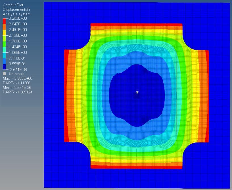
6 First A. Author, Second B. Author and Third C. Author composite panel. Experimental result that shows in the Figure 4 is used to validate the simulation result. Then a sensitivity study is performed on the stacking sequence. 4.1 Validation Step 1: The numerical result is generated by the ABAUSE, the residual strain generate by the thermal environment in the autoclave is shown in the Figure 5. Composite panel edges are constrained during this process, therefore the residual stress is build up at the center of the skin. The internal strain is symmetrically distributed about the skin center and superimposed over different directions. Therefore the highest deflection is located in the middle of the panel. Figure 5: Residual stress distribute Step 2: Simulation is restated based on the Step1, the residual stress from the Step1 is the load input. Boundary conditions on the mode is changed, constrains along the edges are removed and replaced by a signal point constrain at the middle. During this step the composite panel is separated Figure 6: Simulated curing deformation result
7
8 First A. Author, Second B. Author and Third C. Author [3] S. R. White and H. T. Hahn. Process Modeling of Composite Materials: Residual Stress Development during Cure. Part I : Model Formulation. Journal of Composite materials (16): [4] S. R. White and H. T. Hahn. Process Modeling of Composite Materials: Residual Stress Development during Cure. Part II : Experimental Validation. Journal of composite materials (16): [5] T. A. Bogetti and J. W. Gillespie, Jr. Two-Dimensional Cure Simulation of Thick Thermosetting Composite. Journal of Composite Materials. 1991,25(3): [6] T. A. Bogetti and J. W. Gillespie and R. I. MeCullouqh. Iinfluence of Processing on the Development of Residual Stresses in Thick Section Thermoset Composites International Journal of Materials & Product Technology. 1994, 9(1-3): [7] G.Twigg, A. Poursartip and G. Fernlund. Tool-part Interaction in Composite Processing. Part I: Experimental Investigation and analytical Model. Composites Part A : [8] G.Twigg, A. Poursartip and G. Fernlund. Tool-part Interaction in Composite Processing. Part II: Numerical Modeling. Composite Part A.2004,
ME 475 FEA of a Composite Panel
 ME 475 FEA of a Composite Panel Objectives: To determine the deflection and stress state of a composite panel subjected to asymmetric loading. Introduction: Composite laminates are composed of thin layers
EXACT BUCKLING SOLUTION OF COMPOSITE WEB/FLANGE ASSEMBLY
 EXACT BUCKLING SOLUTION OF COMPOSITE WEB/FLANGE ASSEMBLY J. Sauvé 1*, M. Dubé 1, F. Dervault 2, G. Corriveau 2 1 Ecole de technologie superieure, Montreal, Canada 2 Airframe stress, Advanced Structures,
FINITE ELEMENT ANALYSIS OF A COMPOSITE CATAMARAN
 NAFEMS WORLD CONGRESS 2013, SALZBURG, AUSTRIA FINITE ELEMENT ANALYSIS OF A COMPOSITE CATAMARAN Dr. C. Lequesne, Dr. M. Bruyneel (LMS Samtech, Belgium); Ir. R. Van Vlodorp (Aerofleet, Belgium). Dr. C. Lequesne,
Validation Report: Additional Data Mapping to Structural Analysis Packages
 Autodesk Moldflow Structural Alliance 2012 Validation Report: Additional Data Mapping to Structural Analysis Packages Mapping process-induced stress data from Autodesk Moldflow Insight Dual Domain and
Finite Element Buckling Analysis Of Stiffened Plates
 International Journal of Engineering Research and Development e-issn: 2278-067X, p-issn: 2278-800X, www.ijerd.com Volume 10, Issue 2 (February 2014), PP.79-83 Finite Element Buckling Analysis Of Stiffened
Finite Element Modeling and Failure Analysis of Roll Bending. Forming of GLARE Laminates
 Finite Element Modeling and Failure Analysis of Roll Bending Forming of GLARE Laminates Jingming Tian, Gang Tao, Cheng Liu, Huaguan Li, Xian Zhang, Jie Tao* College of Materials Science and Technology,
OPTIMIZATION OF STIFFENED LAMINATED COMPOSITE CYLINDRICAL PANELS IN THE BUCKLING AND POSTBUCKLING ANALYSIS.
 OPTIMIZATION OF STIFFENED LAMINATED COMPOSITE CYLINDRICAL PANELS IN THE BUCKLING AND POSTBUCKLING ANALYSIS. A. Korjakin, A.Ivahskov, A. Kovalev Stiffened plates and curved panels are widely used as primary
Simulation of fiber reinforced composites using NX 8.5 under the example of a 3- point-bending beam
 R Simulation of fiber reinforced composites using NX 8.5 under the example of a 3- point-bending beam Ralph Kussmaul Zurich, 08-October-2015 IMES-ST/2015-10-08 Simulation of fiber reinforced composites
Revised Sheet Metal Simulation, J.E. Akin, Rice University
 Revised Sheet Metal Simulation, J.E. Akin, Rice University A SolidWorks simulation tutorial is just intended to illustrate where to find various icons that you would need in a real engineering analysis.
Step Change in Design: Exploring Sixty Stent Design Variations Overnight
 Step Change in Design: Exploring Sixty Stent Design Variations Overnight Frank Harewood, Ronan Thornton Medtronic Ireland (Galway) Parkmore Business Park West, Ballybrit, Galway, Ireland frank.harewood@medtronic.com
NUMERICAL DESIGN OPTIMISATION OF A COMPOSITE REACTION LINK
 THE 19 TH INTERNATIONAL CONFERENCE ON COMPOSITE MATERIALS NUMERICAL DESIGN OPTIMISATION OF A COMPOSITE REACTION LINK Y. Yang*, C. Schuhler, T. London, C. Worrall TWI Ltd, Granta Park, Cambridge CB21 6AL
Example 24 Spring-back
 Example 24 Spring-back Summary The spring-back simulation of sheet metal bent into a hat-shape is studied. The problem is one of the famous tests from the Numisheet 93. As spring-back is generally a quasi-static
Chapter 3 Analysis of Original Steel Post
 Chapter 3. Analysis of original steel post 35 Chapter 3 Analysis of Original Steel Post This type of post is a real functioning structure. It is in service throughout the rail network of Spain as part
A NEW APPROACH IN STACKING SEQUENCE OPTIMIZATION OF COMPOSITE LAMINATES USING GENESIS STRUCTURAL ANALYSIS AND OPTIMIZATION SOFTWARE
 9th AIAA/ISSMO Symposium on Multidisciplinary Analysis and Optimization 4-6 September 2002, Atlanta, Georgia AIAA 2002-5451 A NEW APPROACH IN STACKING SEQUENCE OPTIMIZATION OF COMPOSITE LAMINATES USING
MSC/PATRAN LAMINATE MODELER COURSE PAT 325 Workbook
 MSC/PATRAN LAMINATE MODELER COURSE PAT 325 Workbook P3*V8.0*Z*Z*Z*SM-PAT325-WBK - 1 - - 2 - Table of Contents Page 1 Composite Model of Loaded Flat Plate 2 Failure Criteria for Flat Plate 3 Making Plies
Computer Life (CPL) ISSN: Finite Element Analysis of Bearing Box on SolidWorks
 ISSN: Finite Element Analysis of Bearing Box on SolidWorks") Computer Life (CPL) ISSN: 1819-4818 Delivering Quality Science to the World Finite Element Analysis of Bearing Box on SolidWorks Chenling Zheng 1, a, Hang Li 1, b and Jianyong Li 1, c 1 Shandong University
Computer Life (CPL) ISSN: 1819-4818 Delivering Quality Science to the World Finite Element Analysis of Bearing Box on SolidWorks Chenling Zheng 1, a, Hang Li 1, b and Jianyong Li 1, c 1 Shandong University
CHAPTER 4. Numerical Models. descriptions of the boundary conditions, element types, validation, and the force
 CHAPTER 4 Numerical Models This chapter presents the development of numerical models for sandwich beams/plates subjected to four-point bending and the hydromat test system. Detailed descriptions of the
Engineering Effects of Boundary Conditions (Fixtures and Temperatures) J.E. Akin, Rice University, Mechanical Engineering
 J.E. Akin, Rice University, Mechanical Engineering") Engineering Effects of Boundary Conditions (Fixtures and Temperatures) J.E. Akin, Rice University, Mechanical Engineering Here SolidWorks stress simulation tutorials will be re-visited to show how they
Engineering Effects of Boundary Conditions (Fixtures and Temperatures) J.E. Akin, Rice University, Mechanical Engineering Here SolidWorks stress simulation tutorials will be re-visited to show how they
VIRTUAL TESTING OF AIRCRAFT FUSELAGE STIFFENED PANELS
 4 TH INTERNATIONAL CONGRESS OF THE AERONAUTICAL SCIENCES VIRTUAL TESTING OF AIRCRAFT FUSELAGE STIFFENED PANELS Peter Linde*, Jürgen Pleitner*, Wilhelm Rust** *Airbus, Hamburg, Germany, **CAD-FE GmbH, Burgdorf
COMSOL BASED 2-D FEM MODEL FOR ULTRASONIC GUIDED WAVE PROPAGATION IN SYMMETRICALLY DELAMINATED UNIDIRECTIONAL MULTI- LAYERED COMPOSITE STRUCTURE
 Proceedings of the National Seminar & Exhibition on Non-Destructive Evaluation NDE 2011, December 8-10, 2011 COMSOL BASED 2-D FEM MODEL FOR ULTRASONIC GUIDED WAVE PROPAGATION IN SYMMETRICALLY DELAMINATED
Application of a FEA Model for Conformability Calculation of Tip Seal in Compressor
 Purdue University Purdue e-pubs International Compressor Engineering Conference School of Mechanical Engineering 2008 Application of a FEA Model for Conformability Calculation of Tip Seal in Compressor
Finite Element Method. Chapter 7. Practical considerations in FEM modeling
 Finite Element Method Chapter 7 Practical considerations in FEM modeling Finite Element Modeling General Consideration The following are some of the difficult tasks (or decisions) that face the engineer
Saurabh GUPTA and Prabhu RAJAGOPAL *
 8 th International Symposium on NDT in Aerospace, November 3-5, 2016 More info about this article: http://www.ndt.net/?id=20609 Interaction of Fundamental Symmetric Lamb Mode with Delaminations in Composite
Application of Shell elements to buckling-analyses of thin-walled composite laminates
 Application of Shell elements to buckling-analyses of thin-walled composite laminates B.A. Gӧttgens MT 12.02 Internship report Coach: Dr. R. E. Erkmen University of Technology Sydney Department of Civil
Difficulties in FE-modelling of an I- beam subjected to torsion, shear and bending
 DEGREE PROJECT, IN STEEL STRUCTURES, SECOND LEVEL STOCKHOLM, SWEDEN 2015 Difficulties in FE-modelling of an I- beam subjected to torsion, shear and bending MIRIAM ALEXANDROU KTH ROYAL INSTITUTE OF TECHNOLOGY
ANSYS Element. elearning. Peter Barrett October CAE Associates Inc. and ANSYS Inc. All rights reserved.
 ANSYS Element Selection elearning Peter Barrett October 2012 2012 CAE Associates Inc. and ANSYS Inc. All rights reserved. ANSYS Element Selection What is the best element type(s) for my analysis? Best
Guidelines for proper use of Plate elements
 Guidelines for proper use of Plate elements In structural analysis using finite element method, the analysis model is created by dividing the entire structure into finite elements. This procedure is known
Revision of the SolidWorks Variable Pressure Simulation Tutorial J.E. Akin, Rice University, Mechanical Engineering. Introduction
 Revision of the SolidWorks Variable Pressure Simulation Tutorial J.E. Akin, Rice University, Mechanical Engineering Introduction A SolidWorks simulation tutorial is just intended to illustrate where to
CE Advanced Structural Analysis. Lab 4 SAP2000 Plane Elasticity
 Department of Civil & Geological Engineering COLLEGE OF ENGINEERING CE 463.3 Advanced Structural Analysis Lab 4 SAP2000 Plane Elasticity February 27 th, 2013 T.A: Ouafi Saha Professor: M. Boulfiza 1. Rectangular
The Vibration Characteristics Analysis of Damping System of Wallmounted Airborne Equipment Based on FEM
 IOP Conference Series: Earth and Environmental Science PAPER OPEN ACCESS The Vibration Characteristics Analysis of Damping System of Wallmounted Airborne Equipment Based on FEM To cite this article: Changqing
SIMULATION CAPABILITIES IN CREO
 SIMULATION CAPABILITIES IN CREO Enhance Your Product Design with Simulation & Using digital prototypes to understand how your designs perform in real-world conditions is vital to your product development
ANALYSIS OF A STRINGER RUN-OUT CONCEPT INCLUDING DAMAGE INITIATION AND EVOLUTION AT THE INTERFACES
 ANALYSIS OF A STRINGER RUN-OUT CONCEPT INCLUDING DAMAGE INITIATION AND EVOLUTION AT THE INTERFACES A. Blázquez 1, J. Reinoso 1, F. París 1, A. Estefani 1, E. Arévalo 2, F. Cruz 3 1 Group of Elasticity
LIGO Scissors Table Static Test and Analysis Results
 LIGO-T980125-00-D HYTEC-TN-LIGO-31 LIGO Scissors Table Static Test and Analysis Results Eric Swensen and Franz Biehl August 30, 1998 Abstract Static structural tests were conducted on the LIGO scissors
Behaviour of cold bent glass plates during the shaping process
 Behaviour of cold bent glass plates during the shaping process Kyriaki G. DATSIOU *, Mauro OVEREND a * Department of Engineering, University of Cambridge Trumpington Street, Cambridge, CB2 1PZ, UK kd365@cam.ac.uk
Modelling Flat Spring Performance Using FEA
 Modelling Flat Spring Performance Using FEA Blessing O Fatola, Patrick Keogh and Ben Hicks Department of Mechanical Engineering, University of Corresponding author bf223@bath.ac.uk Abstract. This paper
by Mahender Reddy Concept To Reality / Summer 2006
 by Mahender Reddy Demand for higher extrusion rates, increased product quality and lower energy consumption have prompted plants to use various methods to determine optimum process conditions and die designs.
Targeting Composite Wing Performance Optimising the Composite Lay-Up Design
 Targeting Composite Wing Performance Optimising the Composite Lay-Up Design Sam Patten Optimisation Specialist, Altair Engineering Ltd Imperial House, Holly Walk, Royal Leamington Spa, CV32 4JG sam.patten@uk.altair.com
OPTFAIL Manual. A1.1 Introduction. APPENDIX 1 SPROPS, PROFAIL, and
 APPENDIX 1 SPROPS, PROFAIL, and OPTFAIL Manual A1.1 Introduction OPTFAIL is a computer code written in FORTRAN developed by Woodson (1994) to optimize circular frames laminated from uniaxial tape composites
Mixed Mode Fracture of Through Cracks In Nuclear Reactor Steam Generator Helical Coil Tube
 Journal of Materials Science & Surface Engineering Vol. 3 (4), 2015, pp 298-302 Contents lists available at http://www.jmsse.org/ Journal of Materials Science & Surface Engineering Mixed Mode Fracture
CHAPTER 6 EXPERIMENTAL AND FINITE ELEMENT SIMULATION STUDIES OF SUPERPLASTIC BOX FORMING
 113 CHAPTER 6 EXPERIMENTAL AND FINITE ELEMENT SIMULATION STUDIES OF SUPERPLASTIC BOX FORMING 6.1 INTRODUCTION Superplastic properties are exhibited only under a narrow range of strain rates. Hence, it
Chapter 1 Introduction
 Chapter 1 Introduction GTU Paper Analysis (New Syllabus) Sr. No. Questions 26/10/16 11/05/16 09/05/16 08/12/15 Theory 1. What is graphic standard? Explain different CAD standards. 2. Write Bresenham s
A Multiple Constraint Approach for Finite Element Analysis of Moment Frames with Radius-cut RBS Connections
 A Multiple Constraint Approach for Finite Element Analysis of Moment Frames with Radius-cut RBS Connections Dawit Hailu +, Adil Zekaria ++, Samuel Kinde +++ ABSTRACT After the 1994 Northridge earthquake
CITY AND GUILDS 9210 UNIT 135 MECHANICS OF SOLIDS Level 6 TUTORIAL 15 - FINITE ELEMENT ANALYSIS - PART 1
 Outcome 1 The learner can: CITY AND GUILDS 9210 UNIT 135 MECHANICS OF SOLIDS Level 6 TUTORIAL 15 - FINITE ELEMENT ANALYSIS - PART 1 Calculate stresses, strain and deflections in a range of components under
VOLCANIC DEFORMATION MODELLING: NUMERICAL BENCHMARKING WITH COMSOL
 VOLCANIC DEFORMATION MODELLING: NUMERICAL BENCHMARKING WITH COMSOL The following is a description of the model setups and input/output parameters for benchmarking analytical volcanic deformation models
WP1 NUMERICAL BENCHMARK INVESTIGATION
 WP1 NUMERICAL BENCHMARK INVESTIGATION 1 Table of contents 1 Introduction... 3 2 1 st example: beam under pure bending... 3 2.1 Definition of load application and boundary conditions... 4 2.2 Definition
Chapter 7 Practical Considerations in Modeling. Chapter 7 Practical Considerations in Modeling
 CIVL 7/8117 1/43 Chapter 7 Learning Objectives To present concepts that should be considered when modeling for a situation by the finite element method, such as aspect ratio, symmetry, natural subdivisions,
 Set No. 1 IV B.Tech. I Semester Regular Examinations, November 2010 FINITE ELEMENT METHODS (Mechanical Engineering) Time: 3 Hours Max Marks: 80 Answer any FIVE Questions All Questions carry equal marks
FE ANALYSES OF STABILITY OF SINGLE AND DOUBLE CORRUGATED BOARDS
 Proceedings of ICAD26 FE ANALYSES OF STABILITY OF SINGLE AND DOUBLE CORRUGATED BOARDS ICAD-26-43 Enrico Armentani enrico.armentani@unina.it University of Naples P.le V. Tecchio, 8 8125 Naples Italy Francesco
Exercise 1. 3-Point Bending Using the GUI and the Bottom-up-Method
 Exercise 1 3-Point Bending Using the GUI and the Bottom-up-Method Contents Learn how to... 1 Given... 2 Questions... 2 Taking advantage of symmetries... 2 A. Preprocessor (Setting up the Model)... 3 A.1
Introduction to Abaqus. About this Course
 Introduction to Abaqus R 6.12 About this Course Course objectives Upon completion of this course you will be able to: Use Abaqus/CAE to create complete finite element models. Use Abaqus/CAE to submit and
ENGINEERING TRIPOS PART IIA FINITE ELEMENT METHOD
 ENGINEERING TRIPOS PART IIA LOCATION: DPO EXPERIMENT 3D7 FINITE ELEMENT METHOD Those who have performed the 3C7 experiment should bring the write-up along to this laboratory Objectives Show that the accuracy
FINITE ELEMENT MODELLING AND ANALYSIS OF WORKPIECE-FIXTURE SYSTEM
 FINITE ELEMENT MODELLING AND ANALYSIS OF WORKPIECE-FIXTURE SYSTEM N. M. KUMBHAR, G. S. PATIL, S. S. MOHITE & M. A. SUTAR Dept. of Mechanical Engineering, Govt. College of Engineering, Karad, Dist- Satara,
Module 1: Introduction to Finite Element Analysis. Lecture 4: Steps in Finite Element Analysis
 25 Module 1: Introduction to Finite Element Analysis Lecture 4: Steps in Finite Element Analysis 1.4.1 Loading Conditions There are multiple loading conditions which may be applied to a system. The load
Introduction to Finite Element Analysis using ANSYS
 Introduction to Finite Element Analysis using ANSYS Sasi Kumar Tippabhotla PhD Candidate Xtreme Photovoltaics (XPV) Lab EPD, SUTD Disclaimer: The material and simulations (using Ansys student version)
ANSYS Workbench Guide
 ANSYS Workbench Guide Introduction This document serves as a step-by-step guide for conducting a Finite Element Analysis (FEA) using ANSYS Workbench. It will cover the use of the simulation package through
TABLE OF CONTENTS SECTION 2 BACKGROUND AND LITERATURE REVIEW... 3 SECTION 3 WAVE REFLECTION AND TRANSMISSION IN RODS Introduction...
 TABLE OF CONTENTS SECTION 1 INTRODUCTION... 1 1.1 Introduction... 1 1.2 Objectives... 1 1.3 Report organization... 2 SECTION 2 BACKGROUND AND LITERATURE REVIEW... 3 2.1 Introduction... 3 2.2 Wave propagation
First International Symposium on Flutter and its Application, STRUCTURAL DESIGN OF MORPHING CONTROL SURFACE USING CORRUGATED PANELS Sato Keig
 First International Symposium on Flutter and its Application, 2016 105 STRUCTURAL DESIGN OF MORPHING CONTROL SURFACE USING CORRUGATED PANELS Sato Keigo +1 and Yokozeki Tomohiro +2 +1, +2 University of
Predicting the mechanical behaviour of large composite rocket motor cases
 High Performance Structures and Materials III 73 Predicting the mechanical behaviour of large composite rocket motor cases N. Couroneau DGA/CAEPE, St Médard en Jalles, France Abstract A method to develop
Multilevel optimization of. of Composite panels under complex load and boundary conditions.
 Loughborough University Institutional Repository Multilevel optimization of composite panels under complex load and boundary conditions This item was submitted to Loughborough University's Institutional
COMPUTER AIDED ENGINEERING. Part-1
 COMPUTER AIDED ENGINEERING Course no. 7962 Finite Element Modelling and Simulation Finite Element Modelling and Simulation Part-1 Modeling & Simulation System A system exists and operates in time and space.
COMPLIANCE MODELLING OF 3D WEAVES
 6 TH INTERNATIONAL CONFERENCE ON COMPOSITE MATERIALS COMPLIANCE MODELLING OF 3D WEAVES Prasad Potluri *, Andrew Long **, Robert J Young *, Hua Lin **, Yat-Tarng Shyng *, A Manan * * School of Materials,
MODELLING OF AN AUTOMOBILE TYRE USING LS-DYNA3D
 MODELLING OF AN AUTOMOBILE TYRE USING LS-DYNA3D W. Hall, R. P. Jones, and J. T. Mottram School of Engineering, University of Warwick, Coventry, CV4 7AL, UK ABSTRACT: This paper describes a finite element
Creo Simulate 3.0 Tutorial
 Creo Simulate 3.0 Tutorial Structure and Thermal Roger Toogood, Ph.D., P. Eng. SDC PUBLICATIONS Better Textbooks. Lower Prices. www.sdcpublications.com Powered by TCPDF (www.tcpdf.org) Visit the following
MAE 323: Lab 7. Instructions. Pressure Vessel Alex Grishin MAE 323 Lab Instructions 1
 Instructions MAE 323 Lab Instructions 1 Problem Definition Determine how different element types perform for modeling a cylindrical pressure vessel over a wide range of r/t ratios, and how the hoop stress
Study of Convergence of Results in Finite Element Analysis of a Plane Stress Bracket
 RESEARCH ARTICLE OPEN ACCESS Study of Convergence of Results in Finite Element Analysis of a Plane Stress Bracket Gowtham K L*, Shivashankar R. Srivatsa** *(Department of Mechanical Engineering, B. M.
An Introduction to Tolerance Analysis of Flexible Assemblies
 An Introduction to Tolerance Analysis of Flexible Assemblies K. G. Merkley, K. W. Chase, E. Perry Brigham Young University Provo, UT Abstract Tolerance analysis is used to predict the effects of manufacturing
Computational Simulation of the Wind-force on Metal Meshes
 16 th Australasian Fluid Mechanics Conference Crown Plaza, Gold Coast, Australia 2-7 December 2007 Computational Simulation of the Wind-force on Metal Meshes Ahmad Sharifian & David R. Buttsworth Faculty
Challenge Problem 5 - The Solution Dynamic Characteristics of a Truss Structure
 Challenge Problem 5 - The Solution Dynamic Characteristics of a Truss Structure In the final year of his engineering degree course a student was introduced to finite element analysis and conducted an assessment
Strain-Based Finite Element Analysis of Stiffened Cylindrical Shell Roof
 American Journal of Civil Engineering 2017; 5(4): 225-230 http://www.sciencepublishinggroup.com/j/ajce doi: 10.11648/j.ajce.20170504.15 ISSN: 2330-8729 (Print); ISSN: 2330-8737 (Online) Strain-Based Finite
Embedded Reinforcements
 Embedded Reinforcements Gerd-Jan Schreppers, January 2015 Abstract: This paper explains the concept and application of embedded reinforcements in DIANA. Basic assumptions and definitions, the pre-processing
THERMAL EXPANSION OF A NAVIGABLE LOCK
 THERMAL EXPANSION OF A NAVIGABLE LOCK 15 THERMAL EXPANSION OF A NAVIGABLE LOCK A navigable lock is temporarily 'empty' due to maintenance. After some time there is significant increase of the air temperature,
High-fidelity Structural Optimization of a Tow-Steered Composite Wing
 11 th World Congress on Structural and Multidisciplinary Optimization 7 th - 12 th, June 2015, Sydney Australia High-fidelity Structural Optimization of a Tow-Steered Composite Wing Timothy R. Brooks 1,
SIMULATION CAPABILITIES IN CREO. Enhance Your Product Design with Simulation & Analysis
 SIMULATION CAPABILITIES IN CREO Enhance Your Product Design with Simulation & Using digital prototypes to understand how your designs perform in real-world conditions is vital to your product development
Krzysztof Dabrowiecki, Probe2000 Inc Southwest Test Conference, San Diego, CA June 08, 2004
 Structural stability of shelf probe cards Krzysztof Dabrowiecki, Probe2000 Inc Southwest Test Conference, San Diego, CA June 08, 2004 Presentation Outline Introduction Objectives Multi die applications
Non-Linear Analysis of Bolted Flush End-Plate Steel Beam-to-Column Connection Nur Ashikin Latip, Redzuan Abdulla
 Non-Linear Analysis of Bolted Flush End-Plate Steel Beam-to-Column Connection Nur Ashikin Latip, Redzuan Abdulla 1 Faculty of Civil Engineering, Universiti Teknologi Malaysia, Malaysia redzuan@utm.my Keywords:
IJSRD - International Journal for Scientific Research & Development Vol. 3, Issue 07, 2015 ISSN (online):
:") IJSRD - International Journal for Scientific Research & Development Vol. 3, Issue 07, 2015 ISSN (online): 2321-0613 Uncertainty Analysis of Hollow Rectangular Beam by using Finite Element Method Mr. Sachin
IJSRD - International Journal for Scientific Research & Development Vol. 3, Issue 07, 2015 ISSN (online): 2321-0613 Uncertainty Analysis of Hollow Rectangular Beam by using Finite Element Method Mr. Sachin
Linear and Nonlinear Analysis of a Cantilever Beam
 LESSON 1 Linear and Nonlinear Analysis of a Cantilever Beam P L Objectives: Create a beam database to be used for the specified subsequent exercises. Compare small vs. large displacement analysis. Linear
Top Layer Subframe and Node Analysis
 Top Layer Subframe and Node Analysis By Paul Rasmussen 2 August, 2012 Introduction The top layer of the CCAT backing structure forms a critical interface between the truss and the primary subframes. Ideally
DEVELOPMENT OF A NUMERICAL MODEL FOR SIMULATIONS OF SPLIT HOPKINSON PRESSURE BAR
 DEVELOPMENT OF A NUMERICAL MODEL FOR SIMULATIONS OF SPLIT HOPKINSON PRESSURE BAR Afdhal 1, Annisa Jusuf 1, Muhammad Agus Kariem 2 and Leonardo Gunawan 1 1 Lightweight Structures Research Group, Faculty
Case Study- Importing As-Molded Plastic Part Conditions into CAE tools
 1 IEI Innova Engineering 1 Park Plaza Suite 980 Irvine, California 92614 Case Study- Importing As-Molded Plastic Part Conditions into CAE tools 2 CONTENTS CONTENTS... 2 EXECUTIVE SUMMARY... 3 APPROACH...
Guangxi University, Nanning , China *Corresponding author
 2017 2nd International Conference on Applied Mechanics and Mechatronics Engineering (AMME 2017) ISBN: 978-1-60595-521-6 Topological Optimization of Gantry Milling Machine Based on Finite Element Method
STATIC AND DYNAMIC ANALYSIS OF COMPOSITE ROTOR BLADE
 STATIC AND DYNAMIC ANALYSIS OF COMPOSITE ROTOR BLADE Dr. M. Murali Krishna 1, G. Siva Karuna 2 1 Professor, 2 Associate Professor, Department of Mechanical Engineering Sai Ganapathi College of Engineering,
An explicit feature control approach in structural topology optimization
 th World Congress on Structural and Multidisciplinary Optimisation 07 th -2 th, June 205, Sydney Australia An explicit feature control approach in structural topology optimization Weisheng Zhang, Xu Guo
Principal Roll Structure Design Using Non-Linear Implicit Optimisation in Radioss
 Principal Roll Structure Design Using Non-Linear Implicit Optimisation in Radioss David Mylett, Dr. Simon Gardner Force India Formula One Team Ltd. Dadford Road, Silverstone, Northamptonshire, NN12 8TJ,
Using three-dimensional CURVIC contact models to predict stress concentration effects in an axisymmetric model
 Boundary Elements XXVII 245 Using three-dimensional CURVIC contact models to predict stress concentration effects in an axisymmetric model J. J. Rencis & S. R. Pisani Department of Mechanical Engineering,
DESIGN OF MULTI CONTACT AIDED CELLULAR COMPLIANT MECHANISMS FOR STRESS RELIEF
 International Journal of Technical Innovation in Modern Engineering & Science (IJTIMES) Impact Factor: 5.22 (SJIF-2017), e-issn: 2455-2585 Volume 4, Issue 6, June-2018 DESIGN OF MULTI CONTACT AIDED CELLULAR
ANSYS AIM Tutorial Structural Analysis of a Plate with Hole
 ANSYS AIM Tutorial Structural Analysis of a Plate with Hole Author(s): Sebastian Vecchi, ANSYS Created using ANSYS AIM 18.1 Problem Specification Pre-Analysis & Start Up Analytical vs. Numerical Approaches
3D Finite Element Software for Cracks. Version 3.2. Benchmarks and Validation
 3D Finite Element Software for Cracks Version 3.2 Benchmarks and Validation October 217 1965 57 th Court North, Suite 1 Boulder, CO 831 Main: (33) 415-1475 www.questintegrity.com http://www.questintegrity.com/software-products/feacrack
Design and optimisation of an Ariane 5 LOX line cover Mode-tracking in B2000
 Design and optimisation of an Ariane 5 LOX line cover Mode-tracking in B2000 R.J.C. Creemers Nationaal Lucht- en Ruimtevaartlaboratorium National Aerospace Laboratory NLR Design and optimisation of an
The part to be analyzed is the bracket from the tutorial of Chapter 3.
 Introduction to Solid Modeling Using SolidWorks 2007 COSMOSWorks Tutorial Page 1 In this tutorial, we will use the COSMOSWorks finite element analysis (FEA) program to analyze the response of a component
CHAPTER-10 DYNAMIC SIMULATION USING LS-DYNA
 DYNAMIC SIMULATION USING LS-DYNA CHAPTER-10 10.1 Introduction In the past few decades, the Finite Element Method (FEM) has been developed into a key indispensable technology in the modeling and simulation
Global to Local Model Interface for Deepwater Top Tension Risers
 Global to Local Model Interface for Deepwater Top Tension Risers Mateusz Podskarbi Karan Kakar 2H Offshore Inc, Houston, TX Abstract The water depths from which oil and gas are being produced are reaching
Quarter Symmetry Tank Stress (Draft 4 Oct 24 06)
") Quarter Symmetry Tank Stress (Draft 4 Oct 24 06) Introduction You need to carry out the stress analysis of an outdoor water tank. Since it has quarter symmetry you start by building only one-fourth of
Quarter Symmetry Tank Stress (Draft 4 Oct 24 06) Introduction You need to carry out the stress analysis of an outdoor water tank. Since it has quarter symmetry you start by building only one-fourth of
Exercise 1. 3-Point Bending Using the Static Structural Module of. Ansys Workbench 14.0
 Exercise 1 3-Point Bending Using the Static Structural Module of Contents Ansys Workbench 14.0 Learn how to...1 Given...2 Questions...2 Taking advantage of symmetries...2 A. Getting started...3 A.1 Choose
PARALLEL ENGINEERING SIMULATIONS BASED ON FORMING SIMULATION OF A HEAT EXCHANGER PLATE
 PARALLEL ENGINEERING SIMULATIONS BASED ON FORMING SIMULATION OF A HEAT EXCHANGER PLATE Gabrielson P.*, Thuvesen D.** * Alfa Laval Lund AB Box 74, S-221 00 LUND, Sweden & Div. of Production and Materials
Investigating the influence of local fiber architecture in textile composites by the help of a mapping tool
 Investigating the influence of local fiber architecture in textile composites by the help of a mapping tool M. Vinot 1, Martin Holzapfel 1, Christian Liebold 2 1 Institute of Structures and Design, German
PLAXIS 2D - SUBMERGED CONSTRUCTION OF AN EXCAVATION
 PLAXIS 2D - SUBMERGED CONSTRUCTION OF AN EXCAVATION 3 SUBMERGED CONSTRUCTION OF AN EXCAVATION This tutorial illustrates the use of PLAXIS for the analysis of submerged construction of an excavation. Most
Solid and shell elements
 Solid and shell elements Theodore Sussman, Ph.D. ADINA R&D, Inc, 2016 1 Overview 2D and 3D solid elements Types of elements Effects of element distortions Incompatible modes elements u/p elements for incompressible
Modeling Foundations in RS
 Modeling Foundations in RS 3 Piled Raft Modeling in RS 3 Deep foundation piles are commonly used to increase foundation stability and to increase the bearing capacity of structural systems. The design
Beams. Lesson Objectives:
 Beams Lesson Objectives: 1) Derive the member local stiffness values for two-dimensional beam members. 2) Assemble the local stiffness matrix into global coordinates. 3) Assemble the structural stiffness