PolygonMap Help. Contents
|
|
|
- Monica Phelps
- 5 years ago
- Views:
Transcription
1 PolygonMap Help Contents Introduction 2 One poly mapping 3 Parameters Rollout 5 Link Rollout 10 Transform Rollout 13 Slice Rollout 14 Viewport Rollout 14 Junction point 15 Additional info 16 Mapping creation procedure 17 Examples of mapping 18 Author Gushchin Nikit (aka NiK)


2 Here will be described version 5.7 of PolygonMap plugin, but most of information will be actual for older and newer versions too. You can buy it here. Introduction For many of 3d-workers mapping is one of the most complicated stage of work. Generally, standart presets of mapping like Box of Cylindrical is enough for many of objects. For more complex objects user needs to use Unwrap UVW modifier, that can be a little difficult to set up. PolygonMap plugin can align texture on polygon to one of its edges, apply all transformations to mapping, and most important thing is creating links between polygons so next poly can inherit mapping from previous. Thus, user can create seamless mapping for complex 3d objects when using of Unwrap UVW is unreasonably difficult. Below there are an examples of this kind of objects.


3 You can make this mapping in less than a minute. One poly mapping So, lets start from simple example and make mapping for just one polygon. Create 1 meter Plane with 1 segment and add PolygonMap modifier. In Width field enter value of 1 meter, by the size of our poly. Create a material for our object. In diffuse slot add this default PolygonMap texture. You can copy it from this PDF file with right-click menu (you must select the image first).


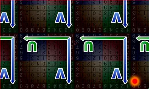
4 Every texture has its coordinates, X and Y axis, but it calls U and V. Horizontal (U) and vertical (V). It calls different cause user can be confused by same axis names while mapping. Our plane has its own mapping of 1 meter size. Thus we didn t get something new, but now we will align mapping to one of edges. This two buttons are responsible for aligning U and V axis to any polygons edge. Green is for horizontal U, blue is for vertical V. However, every edge has 2 points (vertex). To pick point from which texture must mapped you need to click near this point, but cursor also must be near needed edge. This picture approximately shows click zones for every edge and every point. For example, to select point 5 on lower edge you must click somewhere in red zone. So, after clicking a button with green triangle and U letter we must pick an edge on poly. Horizontal axis U of texture will be aligned to this edge. Picked vertex will be a zero coordinate point of texture. Button with blue triangle and V letter works absolutely same way but it aligns V axis instead of U. This picked edges further we will call align edges. If you are too lazy to read description of all features, you can go directly to Mapping creation procedure chapter. It describes how to create mapping with links and align edges.


5 Parameters Rollout Min len Automatically align U axis of a texture to edge with smallest lenght. Max len Automatically align U axis of a texture to edge with biggest lenght. Max len Min len Group Applies one mapping to all polygons. Similar to planar mapping. Group ON Quadrifity PM calculate average area of polygons to create square mapping for each of them. This option can deform textures, but unwrap will be seamless. Quadrifity OFF Quadrifity ON
6 Transformation instruments Move - Move mapping in viewport +Shift - Move with axis constraints +Ctrl - Fast move +Alt - Slow and precise move Rotate - Rotate mapping around pivot point +Ctrl - Fast rotate +Alt - Slow and precise rotate Scale - Scale mapping in viewport +Shift - Scale with axis constraints +Ctrl - Fast scale +Alt - Slow and precise scale Flip - Flip U axis +Alt - Flip V axis Reset - Reset of all tranformation settings and align edges +Shift - Reset of all tranformation settings and align edges, include links Next buttons redefine automatic Max and Min len settings. Allows to select align edge to U axis +Alt - Flip horizontally +Shift - Align the end of axis (right side of texture instead of left) +Ctrl - Align to edge center Двойной клик - Delete align Allows to select align edge to V axis +Alt - Flip vertically +Shift - Align the end of axis (top side of texture instead of bottom) +Ctrl - Align to edge center Двойной клик - Delete align


.")


7 Examples of align U axis to edges. Click zone is marked as red dot. There is no need to examine all this almost similar pictures, it s enough to understand first four of them. However, if you ll not undestand algorithm of aligning to edges, you can find your case in this list. Simple click Texture is rotated because its beginning of coordinates aligned to bottom-right vertex (on bottom edge). Instead of flipping texture it rotates at 180 deg. Flipping of texture by simple click was removed cause of potential problems with thing like normal bump. Next tile of texture is shown under the picture. Texture isn t rotated because its beginning of coordinates aligned to top-left vertex (on top edge). Next tile of texture is shown above the picture. Alt + click - Flip axis (in this case U)


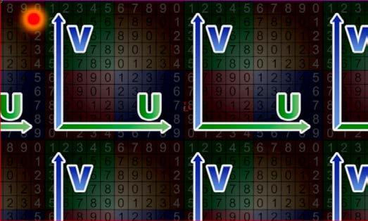
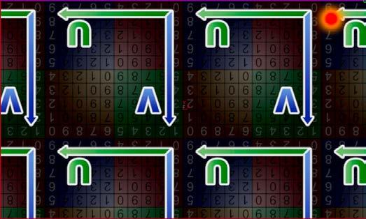
8 Shift + click - Align end of coordinates instead of beginning Alt + Shift + click - Align end of coordinates instead of beginning with flipping Ctrl + click - Align beginning of coordinates to center of an edge Ctrl + Shift и Ctrl + Alt also works Align of V axis done in the same manner.
 +Alt - Pick mapping with material Map channel - Define map channel Weld - On/Off weld vertexes mode.")
9 Pick pivot point and junction point. +Alt - Pick source point instead of junction point (see chapter Junction point). Pick mapping from other polygon (works with other objects too). It also copies transformation settings (see chapter Transform Rollout) +Alt - Pick mapping with material Map channel - Define map channel Weld - On/Off weld vertexes mode. Counter define sensitivity, i.e. minimal distance between vertexes to be welded. Weld OFF Weld ON Get image aspect - Take aspect ratio for mapping from diffuse texture of object s material. Presets - List of saved presets Save - Save settings to preset Remove - Delete selected preset Apply - Apply selected preset

 Counter - Control of automatic links tree 0 - (Default) First branch")
10 Link Rollout Here comes most interest part. Links allows nex polygon inherit mapping of prevoius polygon. In other words - mapping on first polygon seamless continues on second and further along link. Principle of link creation is very simple. Every two neighboring polygons has one common edge, through which link are passes. If you select polygon or link, then in UVW Space window this common edge will become yellow. Links are built like a tree. On - Turn links on Next - Turn on automatic alignment edges creation along link branch (see chapter Mapping creation procedure) Counter - Control of automatic links tree 0 - (Default) First branch will continue to biuld until it hit other link branch or object s border 1 - All branches will continue to build only to 1 next polygon 2 - All branches will continue to build only to 2 next polygons etc. 0 - No build limit. Endless building. 1 - Biuld limit 1. Branches are built only to 1 next polygon. In this example result will be similar, because links are cover whole object in right order anyway. However, in other cases this option might be useful.
11 Also, the counter controls the number of link segments to ring, loop and remove commands. Worth mentioning that a large number of parameters and options in the plugin is just due to the fact that the possible situations of mapping can be endless. For this reason, having to add many seemingly unnecessary features. You will not use them most of the time, but at some point they may prove useful. Automatic - Automatic link creation mode. First - If enabled, the first mapping is applied by automatic, and then by manual links (or base). Disabled by default. by IDs - Generate automatic links based on Material IDs of the object. Link will break at the border of different IDs. by smooth - Generate automatic links based on smoothing groups. Link will break at the border of different smoothing groups. by direction - Generate automatic links based on angle between: edge - edges normal - polygon normals счетчик справа - angle on degrees Links selection mode. By clicking selects the entire link branch and a one polygon. +Shift - Add to selection +Ctrl - Remove from selection Двойной клик - Select all the polygons belonging to a link branch. To create a link you must click anywhere on the polygon and then click on next one. Continue making links as needed by clicking on each next poly. Double click to finish the link and exit creation mode. +Shift (push and hold after the first mouse click) - double click will make link loop and finishes it. The following combinations make it possible to specify the alignment edges along with the links creation. This is a little more difficult, but maybe someone finds it more convenient and faster. Still, its more accurate to do links at first and then adjust alignment edges with tools in the Parameters rollout. +Shift (push and hold before the first mouse click) - along with the link creation allows you to immediately make alignment edges for the U-axis along the link branch. +Shift+Alt - the same for the U-axis but in the opposite direction. +Ctrl - along with the link creation allows you to immediately make alignment edges for the V-axis along the link branch. +Ctrl+Alt - the same for the V-axis but in the opposite direction.
12 Selective conversion of an automatic link to the base/custom links Partial remove mode. To remove a part of the link you need to click at first segment of this part and then continue clicking on each next segment till you reach the end. Remove branch mode. Click anywhere at the branch to delete it. Reset transformation - Resets the transformation and align settings like Reset button in the Parameters rollout, but applied only to polygons of the selected branches. Get from automatic mapping - Convert all automatic links to the base links. Loop - Loop link like edges in polygon modeling. The link is going on in it s direction as possible. Ring - Ring link like edges in polygon modeling. The link will be copied in the perpendicular direction as long as possible. Remove - Remove selected branch. Select prev - Select previous branch (All branches are numbered. Branch number is shown to the right of the red delete button). Select next - Select next branch. Move back - Reducing the sequence number of the selected branch. Move front - Increase the sequence number of the selected branch. Reverse - Changing the direction of the branch to the opposite. Delete all links - Delete all base links.
.")
13 Transform Rollout Use old mapping - Use existing polygon mapping. Blocks nearly all functions of PolygonMap, except for offset and angle. Break map faces - Break mapping vertices. Allowing you to do a random shift or rotate with the existing mapping. Rotate and shift can be made by Offset and Angle counters (+ Rnd). Fit - Enable continuous automatic adjustment of the mapping size to the size of each polygon. Works only if the Links are off, because the size of polygons and mapping will be different. Set size from fit - Adjust mapping size to polygon size. In fact this function is duplicate of the pipette (pick mapping) and F buttons near width and height parameters (see below). Size: Aspt - Lock aspect ratio. The value determines the aspect of mapping (1.0 for a square texture). In this mode, manual editing of the height mapping is not possible, it is calculated automatically from widht (width / aspect ratio). A - Link width of mapping to the align edge length. Width becomes locked. Changing the height is possible. Width - The width of mapping. F - Adjust mapping width to the width of the first polygon. Height - The height of mapping. F - Adjust mapping height to the height of the first polygon. The width and height of the polygon defined by align edges (align edge is wide, and a height perpendicular to it) or sequential numbers of the edges. Lenght - When you assign modifier it applies box mapping. In fact, you don t need to touch this value, and it exists only for informative purposes. Tile: U - U tiling value. Flip - opposite direction. V - The same for V axis. W - The same for W axis. Offset: U - Offset for U axis. Rnd - Random value for each polygon limited by counter. V - The same for V axis. W - The same for W axis. Angle - Mapping rotate angle. Rnd - Random value for each polygon limited by counter. Discr - Use only the specified value multiples. If it s 90 specified, then the available values are 90,180,270,360. If it s 45, then 45,90,135 etc.


14 Slice Rollout В этом свитке можно настроить нарезание полигонов по границам маппинга. On - Включить режим нарезания Preview - Включить/выключить предпросмотр. При включённом предпросмотре нарезка не производится, только демонстрируется. Чтобы сделать нарезку нужно отключить эту галочку. Old map - Использовать для нарезки уже имеющийся на полигонах маппинг. Fissure - Размер шва между нарезанными полигонами. Начиная с версии 5.7 Для работы следующих опций необходимо снять галочку Preview. Nothing - (По умолчанию) оставить швы как есть. Split - Отделить швы от основого объекта на уровне элементов. Delete - Удалить швы. Set ID - Назначить Material ID для швов. Режим нарезки всегда отключается при повторном обращении к PolygonMap в стэке модификаторов, а также при добавлении модификатора. Это не баг. Сделано во избежание зависания программы в случае создания очень большого количества швов при назначении модификатора. Viewport Rollout Show centers and edges - Отображение во вьюпорте выравнивающих ребер и опорных точек. Arrow size - Определяет размер стрелочки относительно вьюпорта. Show links - Отображение во вьюпорте связей Base - Отображение пользовательских связей Auto - Отображение автоматических связей Show UVW space - Открывает окно развертки маппинга Hide unselected - Скрывает невыделенные полигоны в развертке Show grid - Показать сетку в развертке Show map - Показать текстуру в развертке (отображение нужной текстуры должно быть включено в редакторе материалов). Default UVW map - Показать стандартную цветную текстуру с цифрами. Opacity - Прозрачность текстуры во вьюпорте. Scale - Масштаб текстуры. Zoom - Функция находится в разработке. Предполагается зуммирование по выделенному полигону в развертке.

.")
15 Junction point An infinite number of possible geometric shapes and mapping does not allow the plugin to make the right decision in 100% of cases. As already mentioned, each pair of nearby polygons have a common edge, but that edge has two vertex. In most cases, the plugin selects the correct junction point. Otherwise, we must pick the desired vertex. Wrong vertex selection After correction Despite that the polygonss have one common edge, in UVW Unwrap there are two edges, one for each polygon (yellow edges in the first image). This complicates the situation, as each of them has two vertex, and they must be connected in the right order. Thus, the point to which we attach the next polygon we ll call a starting point, and the point on polygon, which he attached to the previous - junction point. The following image should help to understand. a point - starting point for polygon P b point - junction pointfor polygon P By clicking this button you can pick pivot point. Around this point will apply transformations such as scaling and rotation mapping. Also picked point will be a junction point. So, in the first picture the junction point (b) is at the bottom, but the starting point (a) is at the top of the previous poly, as a result lower point attached to the top and UVW was wrong. To change the position of the junction point, you have to click near to the desired point. In our case it is chosen correctly, but we need to change the position of starting point. Alt + click cyclically changes the pick starting point mode and pick junction point mode. You must release the Alt after picking the point. So we need to make Alt+click near lower right vertex of first polygon to pick starting point.
16 Additional info 1. PolygonMap working with selected polygons and edges. If there are selected polygons before in modifier stack, the mapping will be created just for them. If you select one of the edges, this edge will be alignment edge. 2. Pick Mapping tool (pipette) works with different vertex. By clicking on one area you get one result, and click on the other - the result will be different. 3. Pick Mapping tool works with a selected polygon. This means that if you have selected any polygon, then picked mapping size will be adjusted to the size of this polygon. To select the polygon you can use Select Link tool (green arrow in Links Rollout). To remove the selection you can click anywhere outside the polygons. 4. The fit mapping size buttons (F) next to the size values work only by the double click if Links are enabled. When Links are off, fitting works immediately. 5. All transformation tools used in the Parameters Rollout (move, rotate, scale, mirror and alignment edges) are applied to the whole links branch if the Next option is on. It is important to remember, when apply any transformation or alignment. 6. Any transformations resets by double click on the desired polygon. Reset transformations applies to whole link branch. Each transformation can be reset by the same tool. For example, the rotation can be reset by double click only when using the rotate tool, and move transformation will not be reset. To completely reset all transformations you can use Reset tool.

, then hold Shift and double-click on the second.")
17 Mapping creation procedure Here described the easiest and fastest way to build links and mapping. For example, we ll take this object and apply material with default PM texture. Then apply PolygonMap modifier. Last or default settings will be used. If default, then automatiс links will be generated too. Fit Arrow size in Viewport Rollout, so we can clearly see it. Most likely automatic links will be in wrong order, because they will not start from the first polygon. You must avoid this, because there will be a problems with alignment edges. That s why we will disable autolinks and create them yourself. Press Click on the first polygon (building links is best done from left to right), then hold Shift and double-click on the second. That s all, links are done! Next option must be enabled, which means that the transformations (and alignment) will be applied to whole link branch. Then press And select lower edge near first vertex. Click zone is marked by red dot. It remains to adjust the size of our mapping, or simply press the F next to the Height. The height of the mapping will be the same as the height of the polygon. Optionally, you can click Quadrifity, but the texture may be slightly distorted in sharp bends. The same goes for Weld. These two options can lead to similar results, but their effect is different, both are described in the Parameters Rollout chapter.


18 Examples of mapping Plane 50x50 segments Mapping size as polygon size Transform Rollout: Angle 90 Rnd On Discr On Can be used to random mapping of tiles. Correct links and alignment edges on the example of brick walls. Cut all tiles on one walls object. For doors and windows you must set up correct links between polygons. To pick starting point for tiles you can use align U axis tool.


19 Standart Box mapping. PolygonMap mapping with random offset on both axes. Note the different mapping on each shelf. The floor object contains many polygons. Is mapped with only one big texture. Mapping size 3x4 meters, random offset to both axes enabled. As a result, we get a non-repeating textures of flooring on each board, using just one texture.
3ds Max Cottage Step 1. Always start out by setting up units: We re going with this setup as we will round everything off to one inch.
 3ds Max Cottage Step 1 Always start out by setting up units: We re going with this setup as we will round everything off to one inch. File/Import the CAD drawing Be sure Files of Type is set to all formats
Introduction. There are two basic ways to apply more than one texture to one object:
 Introduction For recent versions of Trainz, gmax will not handle the standards for new material types and options such as Specular and Bump or Normal mapping. The Trainz forum has published techniques
Brief 3ds max Shaping Tutorial
 Brief 3ds max Shaping Tutorial Part1: Power Key Axe Shaft Written by Maestro 1. Creation: Go to top view, create a 6 sided cylinder, 0.1 radius this is the perfect shaft thickness to fit in the hand, so
Textures and UV Mapping in Blender
 Textures and UV Mapping in Blender Categories : Uncategorised Date : 21st November 2017 1 / 25 (See below for an introduction to UV maps and unwrapping) Jim s Notes regarding Blender objects, the UV Editor
StickFont Editor v1.01 User Manual. Copyright 2012 NCPlot Software LLC
 StickFont Editor v1.01 User Manual Copyright 2012 NCPlot Software LLC StickFont Editor Manual Table of Contents Welcome... 1 Registering StickFont Editor... 3 Getting Started... 5 Getting Started...
Polygon Modeling Basics Chapter 1 - Vertices
 Polygon Modeling Basics Chapter 1 - Vertices In this tutorial we will cover the basic tools necessary for Polygon Modeling using the Vertex sub-object selection. It is less of a how to tutorial and more
Transforming Objects and Components
 4 Transforming Objects and Components Arrow selection Lasso selection Paint selection Move Rotate Scale Universal Manipulator Soft Modification Show Manipulator Last tool used Figure 4.1 Maya s manipulation
4 TRANSFORMING OBJECTS
 4 TRANSFORMING OBJECTS Lesson overview In this lesson, you ll learn how to do the following: Add, edit, rename, and reorder artboards in an existing document. Navigate artboards. Select individual objects,
ARCHITECTURE & GAMES. A is for Architect Simple Mass Modeling FORM & SPACE. Industry Careers Framework. Applied. Getting Started.
 A is for Architect Simple Mass Modeling One of the first introductions to form and space usually comes at a very early age. As an infant, you might have played with building blocks to help hone your motor
USING THE TRIBALL FOR POSITIONING
 USING THE TRIBALL FOR POSITIONING Although many important positioning tools are available, none are as versatile as the TriBall tool. This TriBall tool offers complete repositioning of many items: Shapes
CGS 3220 Lecture 13 Polygonal Character Modeling
 CGS 3220 Lecture 13 Polygonal Character Modeling Introduction to Computer Aided Modeling Instructor: Brent Rossen Overview Box modeling Polygon proxy Mirroring Polygonal components Topology editing Procedural
How to model a car body in T-Splines
 How to model a car body in T-Splines My name is and I ll show you how to model complex cars like the Alfa Romeo 147 gta using the T-Splines Maya plugin and various techniques. This will be useful if you
Basic Modeling 1 Tekla Structures 12.0 Basic Training September 19, 2006
 Tekla Structures 12.0 Basic Training September 19, 2006 Copyright 2006 Tekla Corporation Contents Contents 3 1 5 1.1 Start Tekla Structures 6 1.2 Create a New Model BasicModel1 7 1.3 Create Grids 10 1.4
Draw Guide. Chapter 3 Working with Objects and Object Points
 Draw Guide Chapter 3 Working with Objects and Object Points Copyright This document is Copyright 2005 2011 by its contributors as listed below. You may distribute it and/or modify it under the terms of
Chapter 1. Getting to Know Illustrator
 Chapter 1 Getting to Know Illustrator Exploring the Illustrator Workspace The arrangement of windows and panels that you see on your monitor is called the workspace. The Illustrator workspace features
Chapter 3- Creating & Editing Objects
 ` Chapter 3- Creating & Editing Objects Edit Mode- Mesh Editing Object Mode After you have created a mesh, you can go into Edit mode (Tab key or Mode option in window) and change its shape. In edit mode,
A Guide to Autodesk Maya 2015
 A Guide to Autodesk Maya 2015 Written by Mitchell Youngerman Table of Contents Layout of Toolbars...pg 1 Creating Objects...pg 2 Selecting & Deselecting Objects...pg 3 Changing Perspective... pg 4 Transforming
Tutorial: How to make low poly car. By Jirayu Tanabodee
 Tutorial: How to make low poly car. By Jirayu Tanabodee I think I would prefer to make my own cars than using stock cars in FSX. Since the cars in FSX always turn their head lamp on, so it is not realistic
On a coordinate plane, such a change can be described by counting the number of spaces, vertically and horizontally, that the figure has moved.
 Transformations We have studied four different kinds of transformations: translation, rotation, reflection, and dilation. Each one involves moving a figure to a new location on a plane. Translation Translation
User Guide. for. JewelCAD Professional Version 2.0
 User Guide Page 1 of 121 User Guide for JewelCAD Professional Version 2.0-1 - User Guide Page 2 of 121 Table of Content 1. Introduction... 7 1.1. Purpose of this document... 7 2. Launch JewelCAD Professional
SETTING UP A. chapter
 1-4283-1960-3_03_Rev2.qxd 5/18/07 8:24 PM Page 1 chapter 3 SETTING UP A DOCUMENT 1. Create a new document. 2. Create master pages. 3. Apply master pages to document pages. 4. Place text and thread text.
Dice in Google SketchUp
 A die (the singular of dice) looks so simple. But if you want the holes placed exactly and consistently, you need to create some extra geometry to use as guides. Plus, using components for the holes is
Word 2013 Quick Start Guide
 Getting Started File Tab: Click to access actions like Print, Save As, and Word Options. Ribbon: Logically organize actions onto Tabs, Groups, and Buttons to facilitate finding commands. Active Document
Basic Blender Commands This is just a partial list of Blender commands. Please visit the Blender.org website for more details.
 Basic Key Commands Basic Blender Commands This is just a partial list of Blender commands. Please visit the Blender.org website for more details. TAB key- Toggles between edit mode (vertex editing) and
Tutorial 4: Texture Mapping Techniques
 Tutorial 4: Texture Mapping Techniques Completion time 40 minutes In the previous tutorial we learned how to create materials, and how to assign texture maps to those materials. In this tutorial we will
ROUNDCORNER 3D-Rounding of Edges and Corners
 1. Overview ROUNDCORNER 3D-Rounding of Edges and Corners QUICKCARD V2.5 30 AUG 13 RoundCorner performs the rounding of the edges and corners of 3D shapes along a 2D profile, by default an arc of circle.
Selective Space Structures Manual
 Selective Space Structures Manual February 2017 CONTENTS 1 Contents 1 Overview and Concept 4 1.1 General Concept........................... 4 1.2 Modules................................ 6 2 The 3S Generator
ROUNDCORNER 3D-Rounding of Edges and Corners
 1. Overview ROUNDCORNER 3D-Rounding of Edges and Corners QUICKCARD V3.0 09 JUL 2015 RoundCorner performs the rounding of the edges and corners of 3D shapes along a 2D profile, by default an arc of circle.
Module 4A: Creating the 3D Model of Right and Oblique Pyramids
 Inventor (5) Module 4A: 4A- 1 Module 4A: Creating the 3D Model of Right and Oblique Pyramids In Module 4A, we will learn how to create 3D solid models of right-axis and oblique-axis pyramid (regular or
Designer Reference 1
 Designer Reference 1 Table of Contents USE OF THE DESIGNER...4 KEYBOARD SHORTCUTS...5 Shortcuts...5 Keyboard Hints...5 MENUS...7 File Menu...7 Edit Menu...8 Favorites Menu...9 Document Menu...10 Item Menu...12
Animation Basics. Learning Objectives
 Animation Basics Learning Objectives After completing this chapter, you will be able to: Work with the time slider Understand animation playback controls Understand animation and time controls Morph compound
Roof Designer USER S GUIDE
 Roof Designer USER S GUIDE Roof Designer-1 Roof Designer-2 Roof Designer The Roof Designer makes it easy to define and place custom roofs in your project. You can start the Roof Designer independently,
LIGHTCONVERSE TOOLS Interface Overview
 MANUAL 1 Contents Contents... 1 LIGHTCONVERSE TOOLS Interface Overview... 2 Tool Manager... 3 Mouse... 4 Mouse Control Operation:... 4 3D Space Area... 4 Modes... 5 Balance Calculator in Warehouse Mode...
An Approach to Content Creation for Trainz
 An Approach to Content Creation for Trainz Paul Hobbs Part 6 GMax Basics (Updates and sample files available from http://www.44090digitalmodels.de) Page 1 of 18 Version 3 Index Foreward... 3 The Interface...
Skateboard. Hanger. in the Feature Manager and click Sketch on the Context toolbar, Fig. 1. Fig. 2
 Chapter 3 Skateboard Hanger A. Sketch1 Lines. Step 1. Click File Menu > New, click Part Metric and OK. Step 2. Click Right Plane in the Feature Manager and click Sketch on the Context toolbar, Fig. 1.
Photoshop / Editing paths
 Photoshop / Editing paths Path segments, components, and points Select a path Adjust path segments Add or delete anchor points Convert between smooth points and corner points Adjust path components Path
It is a good idea to practice View Control tools for 5 minutes at the start of every 3D session, before doing any other work.
 3D View Control Module Overview All the 2D view controls, such as Fit View, Zoom In and Out, Window Area, and Pan, can be used in 3D. As in 2D, elements to the left, right, above, or below can be excluded
Editing Polygons. Adding material/volume: Extrude. Learning objectives
 Learning objectives Be able to: use the Extrude tool to add volume to a polygon know what edge loops are and how to insert edge loops in a polygon cut edges in a polygon know multiple methods of sewing
Unit 1, Lesson 1: Moving in the Plane
 Unit 1, Lesson 1: Moving in the Plane Let s describe ways figures can move in the plane. 1.1: Which One Doesn t Belong: Diagrams Which one doesn t belong? 1.2: Triangle Square Dance m.openup.org/1/8-1-1-2
Lesson 1 Parametric Modeling Fundamentals
 1-1 Lesson 1 Parametric Modeling Fundamentals Create Simple Parametric Models. Understand the Basic Parametric Modeling Process. Create and Profile Rough Sketches. Understand the "Shape before size" approach.
Excel 2013 Intermediate
 Instructor s Excel 2013 Tutorial 2 - Charts Excel 2013 Intermediate 103-124 Unit 2 - Charts Quick Links Chart Concepts Page EX197 EX199 EX200 Selecting Source Data Pages EX198 EX234 EX237 Creating a Chart
SketchUp. SketchUp. Google SketchUp. Using SketchUp. The Tool Set
 Google Google is a 3D Modelling program which specialises in making computer generated representations of real-world objects, especially architectural, mechanical and building components, such as windows,
2. Getting Started When you start GeoGebra, you will see a version of the following window. 1
 Math 5335 Fall 2018 Lab #0: Installing and using GeoGebra This semester you will have a number of lab assignments which require you to use GeoGebra, a dynamic geometry program. GeoGebra lets you explore
Animated Modifiers (Morphing Teapot) Richard J Lapidus
 Richard J Lapidus") Animated Modifiers (Morphing Teapot) Richard J Lapidus Learning Objectives After completing this chapter, you will be able to: Add and adjust a wide range of modifiers. Work in both object and world space
Animated Modifiers (Morphing Teapot) Richard J Lapidus Learning Objectives After completing this chapter, you will be able to: Add and adjust a wide range of modifiers. Work in both object and world space
A 10-minute introduction to. SynRad+ A test-particle Monte Carlo simulator for synchrotron radiation
 A 10-minute introduction to SynRad+ A test-particle Monte Carlo simulator for synchrotron radiation 1 The basics First, let s learn the SynRad+ terminology and the interface in a few slides. Or, if you
Advanced Copy Pro 9.0 Plugin User Guide
 Advanced Copy Pro 9.0 Plugin User Guide UPDATED ON 6/26/2018 PlanSwift Authored by: Dave Hansen 1 Table of Contents Overview... 3 Purchasing and Installation... 4 Purchasing Plugins... 4 Installation and
Google SketchUp. and SketchUp Pro 7. The book you need to succeed! CD-ROM Included! Kelly L. Murdock. Master SketchUp Pro 7 s tools and features
 CD-ROM Included! Free version of Google SketchUp 7 Trial version of Google SketchUp Pro 7 Chapter example files from the book Kelly L. Murdock Google SketchUp and SketchUp Pro 7 Master SketchUp Pro 7 s
SCENE FILE MANIPULATION SCENE FILE MANIPULATION GETTING STARTED MODELING ANIMATION MATERIALS + MAPPING RENDERING. Saving Files. Save.
 SCENE FILE MANIPULATION SCENE FILE MANIPULATION There are several things you can do with a scene file in 3ds Max. You can save a file, save a file temporarily and retrieve it, and combine scene files.
Getting Started with ShowcaseChapter1:
 Chapter 1 Getting Started with ShowcaseChapter1: In this chapter, you learn the purpose of Autodesk Showcase, about its interface, and how to import geometry and adjust imported geometry. Objectives After
SketchUp Quick Start For Surveyors
 SketchUp Quick Start For Surveyors Reason why we are doing this SketchUp allows surveyors to draw buildings very quickly. It allows you to locate them in a plan of the area. It allows you to show the relationship
Lesson 1: Creating T- Spline Forms. In Samples section of your Data Panel, browse to: Fusion 101 Training > 03 Sculpt > 03_Sculpting_Introduction.
 3.1: Sculpting Sculpting in Fusion 360 allows for the intuitive freeform creation of organic solid bodies and surfaces by leveraging the T- Splines technology. In the Sculpt Workspace, you can rapidly
Caustics - Mental Ray
 Caustics - Mental Ray (Working with real caustic generation) In this tutorial we are going to go over some advanced lighting techniques for creating realistic caustic effects. Caustics are the bent reflections
Chapter 3- Creating & Editing Objects
 Working with Basic Meshes Chapter 3- Creating & Editing Objects Now that we know how to move around in Blender, let s start doing some basic building and shaping. In this chapter we will talk about creating
Solidworks 2006 Surface-modeling
 Solidworks 2006 Surface-modeling (Tutorial 2-Mouse) Surface-modeling Solid-modeling A- 1 Assembly Design Design with a Master Model Surface-modeling Tutorial 2A Import 2D outline drawing into Solidworks2006
solidthinking Inspired Tutorials 2009 solidthinking, Inc. for Mac
 solidthinking Inspired Tutorials 2009 solidthinking, Inc. for Mac Table of Contents Quick Start Tutorials 3 Tutorial 11: Simple... Bridge 4 Tutorial 22: Desk... 12 Tutorial 33: Bookcase... 35 2 1 Quick
Creating a Poster in Google SketchUp
 If you have digital image, or can find one online, you can easily make that image into a room poster. For this project, it helps to have some basic knowledge of Google SketchUp (though detailed instructions
CS 465 Program 4: Modeller
 CS 465 Program 4: Modeller out: 30 October 2004 due: 16 November 2004 1 Introduction In this assignment you will work on a simple 3D modelling system that uses simple primitives and curved surfaces organized
Customisation and production of Badges. Getting started with I-Color System Basic Light
 Customisation and production of Badges Getting started with I-Color System Basic Light Table of contents 1 Creating a Badge Model 1.1 Configuration of Badge Format 1.2 Designing your Badge Model 1.2.1
Images from 3D Creative Magazine. 3D Modelling Systems
 Images from 3D Creative Magazine 3D Modelling Systems Contents Reference & Accuracy 3D Primitives Transforms Move (Translate) Rotate Scale Mirror Align 3D Booleans Deforms Bend Taper Skew Twist Squash
Controlling the Drawing Display
 Controlling the Drawing Display In This Chapter 8 AutoCAD provides many ways to display views of your drawing. As you edit your drawing, you can control the drawing display and move quickly to different
LAB # 2 3D Modeling, Properties Commands & Attributes
 COMSATS Institute of Information Technology Electrical Engineering Department (Islamabad Campus) LAB # 2 3D Modeling, Properties Commands & Attributes Designed by Syed Muzahir Abbas 1 1. Overview of the
How to draw and create shapes
 Adobe Flash Professional Guide How to draw and create shapes You can add artwork to your Adobe Flash Professional documents in two ways: You can import images or draw original artwork in Flash by using
XSI TO SINS: COMMANDS & SHORTCUTS
 XSI TO SINS: COMMANDS & SHORTCUTS I. Commonly Used Basic Modeling Commands and Shortcuts in XSI: Section A: The Main Control Panel Select Menu Group/Cluster Selection (See Fig. 1.1 for a quick visual overview)
What is Publisher, anyway?
 What is Publisher, anyway? Microsoft Publisher designed for users who need to create and personalize publications such as marketing materials, business stationery, signage, newsletters and other items
FREDOSCALE - Plugin for Sketchup
 FREDOSCALE - Plugin for Sketchup Free Scaling and Other Transformations VERSION 2.5 01 SEP 13 1. Overview FredoScale applies geometric transformations to a selection. - For many of them, the selection
MET 107 Drawing Tool (Shapes) Notes Day 3
 Notes Day 3") MET 107 Drawing Tool (Shapes) Notes Day 3 Shapes: (Insert Tab Shapes) Example: Select on the rounded rectangle Then use the mouse to position the upper left corner and produce the size by dragging out
MET 107 Drawing Tool (Shapes) Notes Day 3 Shapes: (Insert Tab Shapes) Example: Select on the rounded rectangle Then use the mouse to position the upper left corner and produce the size by dragging out
How to...create a Video VBOX Gauge in Inkscape. So you want to create your own gauge? How about a transparent background for those text elements?
 BASIC GAUGE CREATION The Video VBox setup software is capable of using many different image formats for gauge backgrounds, static images, or logos, including Bitmaps, JPEGs, or PNG s. When the software
User Guide. DrawAnywhere.com: User Guide
 DrawAnywhere.com: User Guide DrawAnywhere.com is an online diagramming & flow charting application with the look & feel of a desktop application! User Guide http://www.drawanywhere.com August, 2007 Table
Chapter 9- Animation Basics
 Timing, Moving, Rotating and Scaling Now that we know how to make stuff and make it look good, it s time to figure out how to move it around in your scene. Another name for an animation is Interpolation
A Study of Angles & Curves
 A Study of Angles & Curves Method 1: Cutting Quilt Shapes/Using the Shapes Tools Open BERNINA CutWork Software. Make sure that Create New is selected. Click Next. Place a dot in front of New Graphic. Select
UV Mapping to avoid texture flaws and enable proper shading
 UV Mapping to avoid texture flaws and enable proper shading Foreword: Throughout this tutorial I am going to be using Maya s built in UV Mapping utility, which I am going to base my projections on individual
VHSE - COMPUTERISED OFFICE MANAGEMENT MODULE III - Communication and Publishing Art - PageMaker
 INTRODUCTION : It is one Adobe PageMaker 7.0 software is the ideal page layout program for business, education, and small- and home-office professionals who want to create high-quality publications such
Working with Charts Stratum.Viewer 6
 Working with Charts Stratum.Viewer 6 Getting Started Tasks Additional Information Access to Charts Introduction to Charts Overview of Chart Types Quick Start - Adding a Chart to a View Create a Chart with
ADOBE ILLUSTRATOR CS3
 ADOBE ILLUSTRATOR CS3 Chapter 2 Creating Text and Gradients Chapter 2 1 Creating type Create and Format Text Create text anywhere Select the Type Tool Click the artboard and start typing or click and drag
Learning to use the drawing tools
 Create a blank slide This module was developed for Office 2000 and 2001, but although there are cosmetic changes in the appearance of some of the tools, the basic functionality is the same in Powerpoint
Editor Guide Version 1.0 Beta
 Editor Guide Version 1.0 Beta Document Version 0.2 Table of Contents Forward... 3 About This Document... 3 Arcane Mapper Goals... 3 Layout... 4 Map Window... 5 Moving Around the Map... 5 Zooming... 5 Changing
Tutorial 1 Engraved Brass Plate R
 Getting Started With Tutorial 1 Engraved Brass Plate R4-090123 Table of Contents What is V-Carving?... 2 What the software allows you to do... 3 What file formats can be used?... 3 Getting Help... 3 Overview
Modeling a Fluted Column in Google SketchUp
 Architectural columns in ancient Greece, Rome, and even China used flutes - vertical grooves cut along the outside of the cylinder. If you want to create a model of an ancient temple, or perhaps one of
Advance Design. Tutorial
 TUTORIAL 2018 Advance Design Tutorial Table of Contents About this tutorial... 1 How to use this guide... 3 Lesson 1: Preparing and organizing your model... 4 Step 1: Start Advance Design... 5 Step 2:
Using Flash Animation Basics
 Using Flash Contents Using Flash... 1 Animation Basics... 1 Exercise 1. Creating a Symbol... 2 Exercise 2. Working with Layers... 4 Exercise 3. Using the Timeline... 6 Exercise 4. Previewing an animation...
You can select polygons that use per-poly UVs by choosing the Select by Polymap command ( View > Selection > Maps > Select by Polygon Map).
.") UV Texture What is UV Mapping? Sometimes, when mapping textures onto objects, you will find that the normal projection mapping just doesn t work. This usually happens when the object is organic, or irregular
UV Texture What is UV Mapping? Sometimes, when mapping textures onto objects, you will find that the normal projection mapping just doesn t work. This usually happens when the object is organic, or irregular
Tekla Structures Analysis Guide. Product version 21.0 March Tekla Corporation
 Tekla Structures Analysis Guide Product version 21.0 March 2015 2015 Tekla Corporation Contents 1 Getting started with analysis... 7 1.1 What is an analysis model... 7 Analysis model objects...9 1.2 About
Maya Lesson 3 Temple Base & Columns
 Maya Lesson 3 Temple Base & Columns Make a new Folder inside your Computer Animation Folder and name it: Temple Save using Save As, and select Incremental Save, with 5 Saves. Name: Lesson3Temple YourName.ma
LESSON 2 MODELING BASICS
 LESSON 2 MODELING BASICS In this lesson we ll start to model a multi-story office building from scratch. We ll construct the base grid, create the two towers and place slabs between the stories. Also we
Tutorial 3: Constructive Editing (2D-CAD)
") (2D-CAD) The editing done up to now is not much different from the normal drawing board techniques. This section deals with commands to copy items we have already drawn, to move them and to make multiple
(2D-CAD) The editing done up to now is not much different from the normal drawing board techniques. This section deals with commands to copy items we have already drawn, to move them and to make multiple
Beaumont Middle School Design Project April May 2014 Carl Lee and Craig Schroeder
 Beaumont Middle School Design Project April May 2014 Carl Lee and Craig Schroeder 1 2 SketchUp 1. SketchUp is free, and you can download it from the website www.sketchup.com. For some K12 use, see www.sketchup.com/3dfor/k12-education.
3. MODELING A THREE-PIPE INTERSECTION (3-D)
") 3. MODELING A THREE-PIPE INTERSECTION (3-D) This tutorial employs primitives that is, predefined GAMBIT modeling components and procedures. There are two types of GAMBIT primitives: Geometry Mesh Geometry
3. MODELING A THREE-PIPE INTERSECTION (3-D) This tutorial employs primitives that is, predefined GAMBIT modeling components and procedures. There are two types of GAMBIT primitives: Geometry Mesh Geometry
This tutorial illustrates how to use TracePro for the analysis of LCD Back Lights. The steps include:
 Requirements Models: None Properties: None Editions: TracePro Expert Introduction This tutorial illustrates how to use TracePro for the analysis of LCD Back Lights. The steps include: Generating a solid
Reconstruct Basics Patrick Parker Aug. 2017
 Reconstruct Basics Patrick Parker Aug. 2017 Trace Palette From the trace palette, you can select the color, name, and shape of the trace you want to make. Here s the Trace Palette: If the Trace Palette
MatterHackers. How to make a 3D model using Google Earth. Written By: Ryan Lutz. How to make a 3D model using Google Earth data
 MatterHackers How to make a 3D model using Google Earth data Written By: Ryan Lutz 2017 matterhackers.dozuki.com Page 1 of 20 INTRODUCTION EDIT 7/25/17: Sadly, Sketchup has changed the map service they
Keys for selecting tools
 Keys for selecting tools Use these shortcuts in the Tools panel. In most cases, you can momentarily switch tools by holding down the keyboard shortcut for the tool. Selection tool V V Rotation tool W W
User Interface Revit s user interface is adaptive, changing based on your selections and views. options. Room Tag Split Elements
 NU REVIT TUTORIAL Instructor: David Snell, AIA LEED AP BD+C Tutorial 1: 2016-01-25 Page 1 of 8 User Interface Revit s user interface is adaptive, changing based on your selections and views. Application
GCC vinyl cutter, cutting plotter for sign making
 Plotter Setup In "Plotter Setup," you can choose "Plotter List," "Environment," "Pen," and so on. [Plotter list] In this area, you can choose the machine type and set some basic information for your plotter
Extrude. Taper. STEP 04: Ctrl +V _ select Copy from the clone window _ name the copy: Slabs Mesh _ click OK
 Extrude STEP 01: open the class-08 3ds Max file _ select the ellipse _ command panel / modifier list _ select Extrude _ set the extrusion Amount: 400 _ STEP 02: with the perspective viewport current press
Tutorials For 3ds Max
 Desk - 3ds Max Modeling Tutorial Tutorials For 3ds Max Tutorials For 3ds Max Desk - 3ds Max Modeling Tutorial Hi everyone. In this 3D modeling tutorial i will show you how to create a Desk using 3d Studio
FormZ Tips created by Phil Jones, edited by Nancy Cheng, University of Oregon 11/16/05
 FormZ Tips created by Phil Jones, edited by Nancy Cheng, University of Oregon 11/16/05 window tools: 1 2 3 4 5 6 7 8 9 1 set reference plane use this to choose between standard reference planes. 2 perpendicular
Xyron Wishblade Software Manual (PC)
") Xyron Wishblade Software Manual (PC) Provided By http://www.mybinding.com http://www.mybindingblog.com Xyron Wishblade Create & Cut Software Manual Section 1 Getting Started with Tool Bars 2 Standard Tool
Xyron Wishblade Software Manual (PC) Provided By http://www.mybinding.com http://www.mybindingblog.com Xyron Wishblade Create & Cut Software Manual Section 1 Getting Started with Tool Bars 2 Standard Tool
1 - Introduction Training Guide Objectives WorkXplore Environment Importing and Opening CAD Files 5
 Table Of Contents 1.1 - Training Guide Objectives Table Of Contents 1 - Introduction 3 1.1 - Training Guide Objectives... 3 1.2 - WorkXplore Environment... 3 2 - Importing and Opening CAD Files 5 2.1 -
ImageVis3D User's Manual
 ImageVis3D User's Manual 1 1. The current state of ImageVis3D Remember : 1. If ImageVis3D causes any kind of trouble, please report this to us! 2. We are still in the process of adding features to the
SketchUp Starting Up The first thing you must do is select a template.
 SketchUp Starting Up The first thing you must do is select a template. While there are many different ones to choose from the only real difference in them is that some have a coloured floor and a horizon