CSE528 Computer Graphics: Theory, Algorithms, and Applications
|
|
|
- Derek Casey
- 5 years ago
- Views:
Transcription
632-845; Fax: (631)632-8334 qin@cs.stonybrook.edu http://www.cs.stonybrook.edu/~qin")
1 CSE528 Computer Graphics: Theory, Algorithms, and Applications Hong Qin Stony Brook University (SUNY at Stony Brook) Stony Brook, New York Tel: (631) ; Fax: (631)
 BR")
2 Geometric Projections From 3D to 2D Maps points from camera coordinate system to the screen (image plane of the virtual camera). Planar Geometric Projections Parallel Perspective Oblique Orthographic Image Plane Image Plane Center of Projection ST NY (COP) BR K

3 Basic Camera Attributes

4 Parallel Orthographic Projection Preserves X and Y coordinates. Preserves both distances and angles. Image Plane
 z y x p = x y p = y z p = (x p, y p, ) z")
5 Parallel Orthographic Projection z y x z y x p p p x (x, y, z) z y x p = x y p = y z p = (x p, y p, ) z =

6 Perspective Projection Only preserves parallel lines that are parallel to the image plane. Line segments are shorten by distance. Image Plane Center of Projection (COP)
7 Perspective Projection y (x, y, z) (x p, y p, z p ) z = d z x
8 Perspective Projection z p = d x p = (x d) / z (x p, d) (x, z) z = d x z
 / z z y (y p, d) (y, z) z =")
9 Perspective Projection z p = d y p = (y d) / z z y (y p, d) (y, z) z = d
, the center of projection 2. Orient the camera to point at what you want to see, the view direction and the view-up direction 3.")
10 Specify a View Volume Reduce degrees of freedom to make the operations easier; four steps to specify a view volume 1. Position the camera (and therefore its view/image plane), the center of projection 2. Orient the camera to point at what you want to see, the view direction and the view-up direction 3. Define field of view: perspective: aspect ratio of image and angle of view: between wide angle, normal, and zoom parallel: width and height 4. Choose perspective or parallel projection

11 Specifying Arbitrary 3D Views Definition of view volume (the visible part of the virtual world) specified by camera s position and orientation Position (a point) Look and Up vectors Shape of view volume specified by horizontal and vertical view angles front and back clipping planes Coordinate Systems world coordinates standard right-handed xyz 3-space camera coordinates camera-space right-handed coordinate system (u, v, n); origin at Position and axes rotated by orientation; used for transforming arbitrary view into canonical view
12 Defining the Parallel View Volume glortho(xmin, xmax, ymin, ymax, near, far) y (x max, y max, -far) (x min, y min, -near) View Volume z x
13 View Volume (Parallel Projection) For example, Orthographic parallel projection: Truncated view volume Cuboid (not exactly a cube!) How about oblique projection??? y Near distance Far distance Look vector Width Height x Up vector z Position
14 Defining the Perspective View Volume y (x max, y max, -far) (x min, y min, -near) z x
15 Defining the Perspective View Volume gluperspective(fovy, aspect, near, far) y w h fov z x
16 View Volume (Perspective Projection) Perspective projection: Truncated pyramid View frustum How about oblique projection???
17 Coordinate Systems
 to a canonical, normalized, device-independent coordinate system, before we can display the final picture")
18 3D Viewing (Computer Graphics Pipeline) We will need to revisit the concept and the techniques for defining 3D viewing coordinate system and specifying 3D view volume for graphics pipeline. We will need to convert 3D view volume (both parallel projection and perspective projection) to a canonical, normalized, device-independent coordinate system, before we can display the final picture in the specified viewport on the display device!

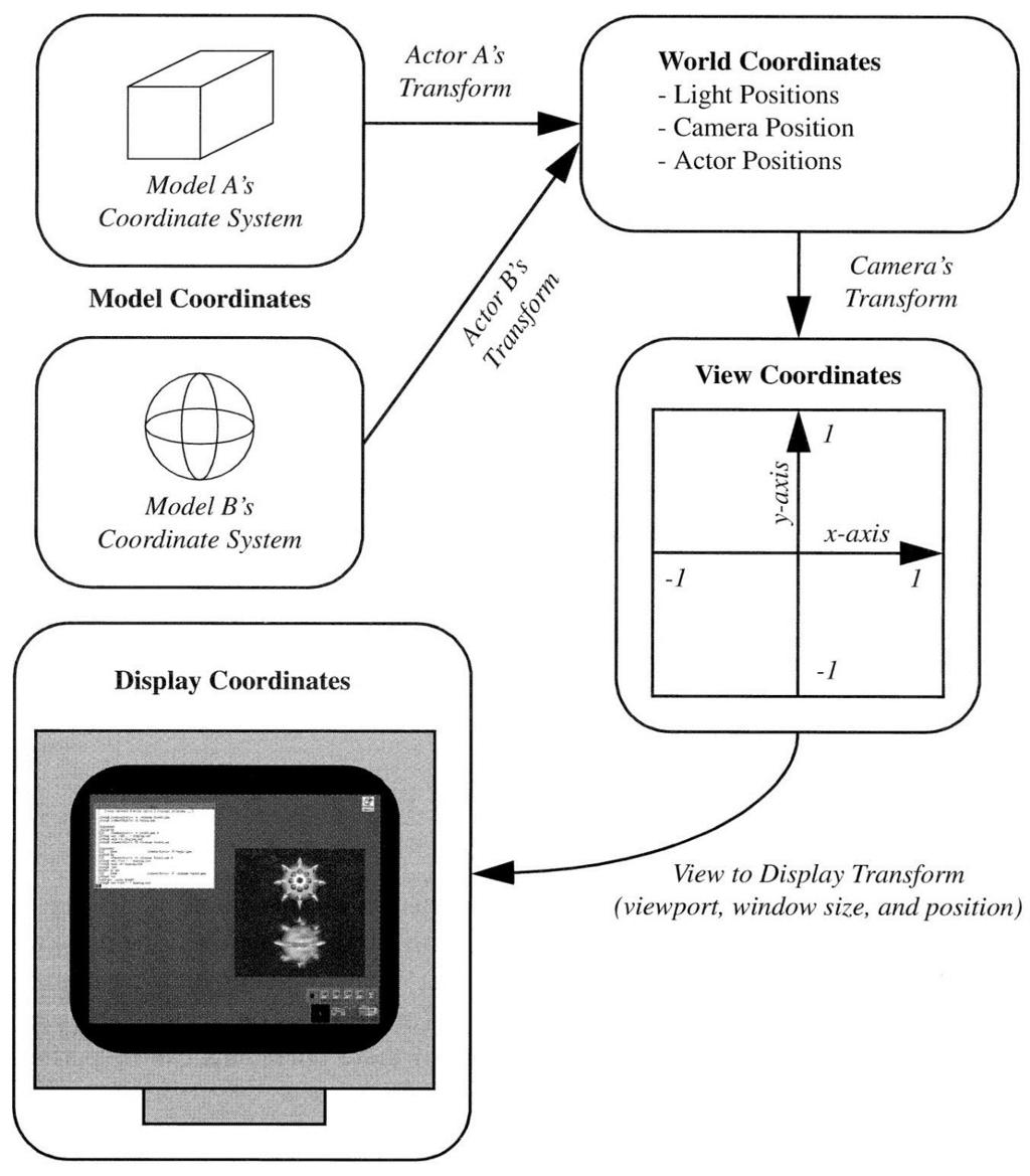
19 Coordinate Systems (Computer Graphics Pipeline) 1. Objects in model coordinates are transformed into 2. World coordinates, which are transformed into 3. View coordinates, which are transformed into 4. Normalized device coordinates, which are transformed into 5. Display coordinates, which correspond to pixel positions on the screen 6. Transformations from one coordinate system to another take place via coordinate transformations, which we have already discussed in previous lectures
 and")
20 Normalizing to the Device Independent View Volume Goal: transform arbitrary view coordinate system to the canonical view volume (device independent), maintaining relationship between view volume and the normalized, device independent coordinate system, then take picture for parallel view volume, transformation is affine : consisting of linear transformations (rotations and scales) and translation/shift in case of a perspective view volume, it also contains a non-affine perspective transformation that turns a frustum into a parallel view volume, a cuboid composite transformation to transform arbitrary view volume to the canonical view volume, named the normalizing transformation, is still a 4x4 homogeneous matrix that typically has an inverse easy to clip against this canonical view volume; clipping planes are axisaligned! projection using canonical view volume is even easier: just omit z- coordinates for oblique parallel projection, a shearing transform is part of composite transform, to de-oblique view volume FIRST!!!
")
 film plane extending from 1 to 1")
21 Canonical View Volume This is the key for today s lecture Up Look z Up parallel projection sits at origin: Position = (,, ) looks along negative z-axis: Look vector = (,, 1) oriented upright: Up vector = (, 1, ) film plane extending from 1 to 1 in x and y

22 Specify Arbitrary 3D Viewing Coordinate System The original of coordinate system Three independent directions (mutually perpendicular with each other)
 z-axis is")
23 Viewing Coordinate System We have specified arbitrary view with viewing parameters Problem: map arbitrary view specification to 2D image of scene. This is hard, both for clipping and for projection Solution: reduce to a simpler problem and solve it step-by-step Note: Look vector along negative (not positive) z-axis is arbitrary but makes math easier!
 Canonical view position (camera at the origin, looking along the negative z-axis) A step-by-step approach 1.")
24 Viewing in Three Dimension The key: Mathematics of projections and its matrix operations How to produce 2D image from view specification? It is relatively easy to specify Canonical view volume (3D parallel projection cuboid) Canonical view position (camera at the origin, looking along the negative z-axis) A step-by-step approach 1. get all parameters for view specification 2. transform from the specified view volume into canonical view volume (This is the key step) 3. using canonical view, clip, project, and rasterize scene to make 2D image

25 From World Coordinate System to View Coordinate System We now know the view specification: Position, Look vector, and Up vector Need to derive an affine transformation from these parameters to translate and rotate the canonical view into our arbitrary view the scaling of the image (i.e. the cross-section of the view volume) to make a square cross-section will happen at a later stage, as will the clipping operation Translation is easy to find: we want to translate the origin to the point Position; therefore, the translation matrix is T ( Position ) Pos Pos Pos 1 x y z Rotation is much harder: how do we generate a rotation matrix from the viewing specifications to turn one system (x, y, z) into another system (u, v, n)?

26 Rotation Components We have already known how to conduct rotation operations with respects to arbitrary axis Also, we have already discussed the transformations between two coordinate systems earlier in our lectures Those techniques should be employed to define three mutually independent axes in 3D and take care of the transformation between the two coordinate systems
 into (u, v, n) and has columns (u, v, n) viewing matrix conversely, M -1 =M T turns (u, v, n) into (x, y, z).")
27 Rotation Matrix Want to build a rotation matrix to normalize the camera-space unit vector axes (u, v, n) into the world-space axes (x, y, z). rotation matrix M will turn (x, y, z) into (u, v, n) and has columns (u, v, n) viewing matrix conversely, M -1 =M T turns (u, v, n) into (x, y, z). M T has rows (u, v, n) normalization matrix Reduces the problem of finding the correct rotation matrix into finding the correct perpendicular unit vectors u, v, and n Using Position, Look vector, and Up vector, compute viewing rotation matrix M with columns u, v, and n, then use its inverse, the transpose M T, with row vectors u, v, n to get the normalization rotation matrix


28 Canonical View Volume Note: it s a cuboid, not a cube (transformation arithmetic and clipping are easier)

29 Canonical View Given a parallel view specification and vertices of a bunch of objects, we use the normalizing transformation, i.e., the inverse viewing transformation, to normalize the view volume to a cuboid at the origin, then clip, and then project those vertices by ignoring their z values How about Perspective Projection? Normalize the perspective view specification to a unit frustum at the origin looking down the z axis; then transform the perspective view volume into a parallel (cuboid) view volume, simplifying both clipping and projection

30 Steps for Normalizing View Volume (Parallel Projection) We need to decompose this process into multiple steps (each step is a simple matrix) Each step defined by a matrix transformation The product of these matrices defines the entire transformation in one large, composite matrix. The steps comprise: move the eye/camera to the origin transform the view so that (u, v, n) is aligned with (x, y, z) adjust the scales so that the view volume fits between 1 and 1 in x and y, the far clip plane lies at z = 1, the near plane at z =

31 Steps for Normalizing View Volume (Perspective Projection) The earlier processes are the SAME AS that of the parallel projection, but we need to add one more step: distort pyramid to cuboid to achieve perspective distortion to align the near clip plane with z =
 = ( Pos x, Pos y, Pos z ) We will take the matrix as follows, and we will multiply all vertices explicitly (and the camera implicitly) to preserve the relationship between camera and")
32 Perspective Projection (Move the Eye to the Origin) We want to have a matrix to transform (Pos x, Pos y, Pos z ) to (,, ) Solution: it s just the inverse of the viewing translation transformation: (t x, t y, t z ) = ( Pos x, Pos y, Pos z ) We will take the matrix as follows, and we will multiply all vertices explicitly (and the camera implicitly) to preserve the relationship between camera and scene, i.e., for all vertices p This will move Position (the eye point ) to (,, ) T trans 1 1 p' T 1 trans p Pos Pos Pos 1 x y z
33 Axis Alignment Align orientation with respects to x,y,z world coordinate system Normalize proportions of the view volume
 of that rotation, M T, to the scene.")
34 Orientation Alignment Rotate the view volume and align with the world coordinate system We notice that the view transformation matrix M with columns u, v, and n would rotate the x, y, z axes into the u, v, and n axes We now apply the inverse (transpose) of that rotation, M T, to the scene. That is, a matrix with rows u, v, and n will rotate the axes u, v, and n into the axes x, y, and z Define M rot to be this rotation matrix transpose Now every vertex in the scene (and the camera implicitly) is multiplied by the composite matrix M rot T trans We have translated and rotated, so that the Position is at the origin, and the (u, v, n) axes and the (x, y, z) axes are aligned
35 Axis Alignment

36 Scale the View Volume We have moved things more or less to the right position, but the size of the view volume needs to be normalized last affine transformation: scaling Need to be normalized to a square cross-section 2-by-2 units why is that preferable to the unit square? Adjust so that the corners of far clipping plane eventually lie at (+1, +1, 1) One mathematical operation works for both parallel and perspective view volumes Imagine vectors emanating from origin passing through corners of far clipping plane. For perspective view volume, these are edges of volume. For parallel, these lie inside view volume First step: force vectors into 45-degree angles with x and y axes Solution: We shall do this by scaling in x and y
37 View Volume Scaling y y z x z x

38 Scale Boundary Planes Scale independently in x and y: Want to scale in x to make angle 9 degrees cot Need to scale in x by 1 w w 2 tan 2 tan w 2,, 1 tan W 2 Similarly in y
39 Scaling Matrix The scale matrix we need looks like this: S xy cot 2 w cot 2 h 1 1 So our current composite transformation looks like this: S xy M rot T trans
 If we scale in z only, proportions of volume")
40 Scaling Along z-axis Relative proportions of view volume planes are now correct, but the back clipping plane is probably lying at some z 1, and we want all points inside view volume to have z -1 Need to shrink the back plane to be at z = 1 The z distance from the eye to that point has not changed: it s still far (distance to the far clipping plane) If we scale in z only, proportions of volume will change; instead we scale uniformly: 1 S far far 1 far 1 far 1
41 At Present, We Are Here Far plane at z = 1. y (-1,1,-1) (-k,k,-k) z z = -1 x Near clip plane now at z = k (note k > )
 S far takes the far clipping plane and scales it")
42 Now We have Our near-final composite normalizing transformation for canonical perspective view volume: T trans takes the camera s Position and moves the camera to the world origin M rot takes the Look and Up vectors and orients the camera to look down the z axis S xy takes w, h and scales the clipping planes so that the corners are at (±1, ±1) S far takes the far clipping plane and scales it to lie on the z=-1 plane S far S xy M rot T trans

43 Perspective Transformation We have put the perspective view volume into the RIGHT canonical position, orientation and size Let s look at a particular point on the original near clipping plane lying on the Look vector: p Position near Look It gets moved to a new location p on the negative z-axis, say S far S xy M rot T trans p k p
( e 3 ) The xy scaling has no effect, and the far scaling changes this")
44 Perspective Transformation What is the value of k? Trace through the steps. p first gets moved to just near Look This point is then rotated to (near)( e 3 ) The xy scaling has no effect, and the far scaling changes this to, so near far e 3 but far is 1, so -near/far is simply near k near far

![calculation, needs z values to be [ 1], not [ 1 ].](/docs-images/95/124154594/images/45-1.jpg "Perspective transformation must also transform scene to positive range z 1 The matrix")

45 Perspective Transformation Transform points in standard perspective view volume between k and 1 to standard parallel view volume z-buffer, used for visible surface calculation, needs z values to be [ 1], not [ 1 ]. Perspective transformation must also transform scene to positive range z 1 The matrix that does this: (Remember that < k < 1 ) Why not originally align camera to +z axis? 1 D 1 k 1 1 k k 1 Choice is perceptual, we think of looking through a display device into the scene that lies behind window 1

46 Finally, We Have Final transformation: p D persp S far S xy M rot T trans p Note that once the viewing parameters (Position, Up vector, Look vector, Height angle, Aspect ratio, Near, and Far) are known, the matrices can all be computed and multiplied together to get a single 4x4 matrix that is applied to all points of all objects to get them from world space to the standard parallel view volume. What are the rationales for homogeneous coordinates??? D, S, S, M, T persp far xy rot trans
 (-1, 1, ) (-1, -1, 1) Back clip plane transforms to the z=1 plane (1, 1, 1) Note that: This is the")
47 Clipping (A Quick Review) Final steps are clipping and projecting onto the image plane to produce pictures Need to clip scene against sides of view volume However, we ve normalized our view volume into an axis-aligned cuboid that extends from 1 to 1 in x and y and from to 1 in z (-1, 1, 1) (-1, 1, ) (-1, -1, 1) Back clip plane transforms to the z=1 plane (1, 1, 1) Note that: This is the flipped (in z) version of the canonical view volume Clipping is easy! Test x and y components of vertices against +/-1. Test z components against and 1 z (1, -1, 1) y (-1, -1, ) x (1, 1, ) (1, -1, ) Front clip plane transforms to here
48 Clipping in 3D (Generalizations) Cohen-Sutherland regions Clip before perspective division
 y 1 t y t y1 t=1 z 1 t z t z1 t= (x, y, z ) In 2D: (-1, -1) (x, y ) y (1, 1)")
49 Clipping (A Quick Review) Vertices falling within these values are saved, and vertices falling outside get clipped; edges get clipped by knowing x,y or z value at an intersection plane. Substitute x, y, or z = 1 in the corresponding parametric line equations to solve for t x 1 t x t x1 t 1 (x 1, y 1, z 1 ) y 1 t y t y1 t=1 z 1 t z t z1 t= (x, y, z ) In 2D: (-1, -1) (x, y ) y (1, 1) x=1 x (x 1, y 1 ) t 1 t x x 1 x 1 x x tx t x x 1 tx x 1 tx 1
 with by - ignoring z x, y 124 x y 512( x 512( y 1) 1) If viewport is inside a Window Manager s window, then we need to scale down and translate")
50 Projecting to the Screen (Device Coordinates) Can make an image by taking each point and ignoring z to project it onto the xyplane A point (x,y,z) where 1 x, y 1, z 1 turns into the point (x, y ) in screen space (assuming viewport is the entire screen) with by - ignoring z x, y 124 x y 512( x 512( y 1) 1) If viewport is inside a Window Manager s window, then we need to scale down and translate to produce window coordinates Note: because it s a parallel projection we could have projected onto the front plane, the back plane, or any intermediate plane the final pixmap would have been the same
 is composite of all modeling (instance) transformations (CMTM) accumulated during scene graph traversal from root to leaf, composited with the final composite normalizing")
51 From World to Screen The entire problem can be reduced to a composite matrix multiplication of vertices, clipping, and a final matrix multiplication to produce screen coordinates. Final composite matrix (CTM) is composite of all modeling (instance) transformations (CMTM) accumulated during scene graph traversal from root to leaf, composited with the final composite normalizing transformation N applied to the root/world coordinate system: 1) N D persp S far S xy M rot T trans 2) CTM N CMTM 3) 4) P screen P CTM P 512( P 1) for every vertex P defined in its own coordinate system for all clipped P Recap: 1) You will be computing the normalizing transformation matrix N in Camtrans 2) In Sceneview, you will extend your Camera with the ability to traverse and compute composite modeling transformations (CMTMs) to produce a single CTM for each primitive in your scene Aren't homogeneous coordinates wonderfully powerful?
CSE328 Fundamentals of Computer Graphics
 CSE328 Fundamentals of Computer Graphics Hong Qin State University of New York at Stony Brook (Stony Brook University) Stony Brook, New York 794--44 Tel: (63)632-845; Fax: (63)632-8334 qin@cs.sunysb.edu
INTRODUCTION TO COMPUTER GRAPHICS. cs123. It looks like a matrix Sort of. Viewing III. Projection in Practice 1 / 52
 It looks like a matrix Sort of Viewing III Projection in Practice 1 / 52 Arbitrary 3D views } view volumes/frusta spec d by placement and shape } Placement: } Position (a point) } look and up vectors }
INTRODUCTION TO COMPUTER GRAPHICS. It looks like a matrix Sort of. Viewing III. Projection in Practice. Bin Sheng 10/11/ / 52
 cs337 It looks like a matrix Sort of Viewing III Projection in Practice / 52 cs337 Arbitrary 3D views Now that we have familiarity with terms we can say that these view volumes/frusta can be specified
Lecture 3 Sections 2.2, 4.4. Mon, Aug 31, 2009
 Model s Lecture 3 Sections 2.2, 4.4 World s Eye s Clip s s s Window s Hampden-Sydney College Mon, Aug 31, 2009 Outline Model s World s Eye s Clip s s s Window s 1 2 3 Model s World s Eye s Clip s s s Window
Lecture 4. Viewing, Projection and Viewport Transformations
 Notes on Assignment Notes on Assignment Hw2 is dependent on hw1 so hw1 and hw2 will be graded together i.e. You have time to finish both by next monday 11:59p Email list issues - please cc: elif@cs.nyu.edu
Notes on Assignment. Notes on Assignment. Notes on Assignment. Notes on Assignment
 Notes on Assignment Notes on Assignment Objects on screen - made of primitives Primitives are points, lines, polygons - watch vertex ordering The main object you need is a box When the MODELVIEW matrix
CSE452 Computer Graphics
 CSE45 Computer Graphics Lecture 8: Computer Projection CSE45 Lecture 8: Computer Projection 1 Review In the last lecture We set up a Virtual Camera Position Orientation Clipping planes Viewing angles Orthographic/Perspective
CMSC427 Transformations II: Viewing. Credit: some slides from Dr. Zwicker
 CMSC427 Transformations II: Viewing Credit: some slides from Dr. Zwicker What next? GIVEN THE TOOLS OF The standard rigid and affine transformations Their representation with matrices and homogeneous coordinates
2D rendering takes a photo of the 2D scene with a virtual camera that selects an axis aligned rectangle from the scene. The photograph is placed into
 2D rendering takes a photo of the 2D scene with a virtual camera that selects an axis aligned rectangle from the scene. The photograph is placed into the viewport of the current application window. A pixel
Today. Rendering pipeline. Rendering pipeline. Object vs. Image order. Rendering engine Rendering engine (jtrt) Computergrafik. Rendering pipeline
 Computergrafik. Rendering pipeline") Computergrafik Today Rendering pipeline s View volumes, clipping Viewport Matthias Zwicker Universität Bern Herbst 2008 Rendering pipeline Rendering pipeline Hardware & software that draws 3D scenes on
Computergrafik Today Rendering pipeline s View volumes, clipping Viewport Matthias Zwicker Universität Bern Herbst 2008 Rendering pipeline Rendering pipeline Hardware & software that draws 3D scenes on
Three-Dimensional Viewing Hearn & Baker Chapter 7
 Three-Dimensional Viewing Hearn & Baker Chapter 7 Overview 3D viewing involves some tasks that are not present in 2D viewing: Projection, Visibility checks, Lighting effects, etc. Overview First, set up
CSC 305 The Graphics Pipeline-1
 C. O. P. d y! "#"" (-1, -1) (1, 1) x z CSC 305 The Graphics Pipeline-1 by Brian Wyvill The University of Victoria Graphics Group Perspective Viewing Transformation l l l Tools for creating and manipulating
Models and The Viewing Pipeline. Jian Huang CS456
 Models and The Viewing Pipeline Jian Huang CS456 Vertex coordinates list, polygon table and (maybe) edge table Auxiliary: Per vertex normal Neighborhood information, arranged with regard to vertices and
3D Polygon Rendering. Many applications use rendering of 3D polygons with direct illumination
 Rendering Pipeline 3D Polygon Rendering Many applications use rendering of 3D polygons with direct illumination 3D Polygon Rendering What steps are necessary to utilize spatial coherence while drawing
Viewing. Reading: Angel Ch.5
 Viewing Reading: Angel Ch.5 What is Viewing? Viewing transform projects the 3D model to a 2D image plane 3D Objects (world frame) Model-view (camera frame) View transform (projection frame) 2D image View
CS 4204 Computer Graphics
 CS 4204 Computer Graphics 3D Viewing and Projection Yong Cao Virginia Tech Objective We will develop methods to camera through scenes. We will develop mathematical tools to handle perspective projection.
THE VIEWING TRANSFORMATION
 ECS 178 Course Notes THE VIEWING TRANSFORMATION Kenneth I. Joy Institute for Data Analysis and Visualization Department of Computer Science University of California, Davis Overview One of the most important
CSE 167: Introduction to Computer Graphics Lecture #4: Vertex Transformation
 CSE 167: Introduction to Computer Graphics Lecture #4: Vertex Transformation Jürgen P. Schulze, Ph.D. University of California, San Diego Fall Quarter 2013 Announcements Project 2 due Friday, October 11
1 OpenGL - column vectors (column-major ordering)
") OpenGL - column vectors (column-major ordering) OpenGL uses column vectors and matrices are written in a column-major order. As a result, matrices are concatenated in right-to-left order, with the first
OpenGL - column vectors (column-major ordering) OpenGL uses column vectors and matrices are written in a column-major order. As a result, matrices are concatenated in right-to-left order, with the first
Chap 3 Viewing Pipeline Reading: Angel s Interactive Computer Graphics, Sixth ed. Sections 4.1~4.7
 Chap 3 Viewing Pipeline Reading: Angel s Interactive Computer Graphics, Sixth ed. Sections 4.~4.7 Chap 3 View Pipeline, Comp. Graphics (U) CGGM Lab., CS Dept., NCTU Jung Hong Chuang Outline View parameters
CSE528 Computer Graphics: Theory, Algorithms, and Applications
 CSE528 Computer Graphics: Theor, Algorithms, and Applications Hong Qin State Universit of New York at Ston Brook (Ston Brook Universit) Ston Brook, New York 794--44 Tel: (63)632-845; Fa: (63)632-8334 qin@cs.sunsb.edu
Rasterization Overview
 Rendering Overview The process of generating an image given a virtual camera objects light sources Various techniques rasterization (topic of this course) raytracing (topic of the course Advanced Computer
CSE 167: Lecture #4: Vertex Transformation. Jürgen P. Schulze, Ph.D. University of California, San Diego Fall Quarter 2012
 CSE 167: Introduction to Computer Graphics Lecture #4: Vertex Transformation Jürgen P. Schulze, Ph.D. University of California, San Diego Fall Quarter 2012 Announcements Project 2 due Friday, October 12
3D Viewing. CS 4620 Lecture 8
 3D Viewing CS 46 Lecture 8 13 Steve Marschner 1 Viewing, backward and forward So far have used the backward approach to viewing start from pixel ask what part of scene projects to pixel explicitly construct
Computer Graphics 7: Viewing in 3-D
 Computer Graphics 7: Viewing in 3-D In today s lecture we are going to have a look at: Transformations in 3-D How do transformations in 3-D work? Contents 3-D homogeneous coordinates and matrix based transformations
Clipping and Scan Conversion
 15-462 Computer Graphics I Lecture 14 Clipping and Scan Conversion Line Clipping Polygon Clipping Clipping in Three Dimensions Scan Conversion (Rasterization) [Angel 7.3-7.6, 7.8-7.9] March 19, 2002 Frank
I N T R O D U C T I O N T O C O M P U T E R G R A P H I C S
 3D Viewing: the Synthetic Camera Programmer s reference model for specifying 3D view projection parameters to the computer General synthetic camera (e.g., PHIGS Camera, Computer Graphics: Principles and
Graphics pipeline and transformations. Composition of transformations
 Graphics pipeline and transformations Composition of transformations Order matters! ( rotation * translation translation * rotation) Composition of transformations = matrix multiplication: if T is a rotation
Evening s Goals. Mathematical Transformations. Discuss the mathematical transformations that are utilized for computer graphics
 Evening s Goals Discuss the mathematical transformations that are utilized for computer graphics projection viewing modeling Describe aspect ratio and its importance Provide a motivation for homogenous
Viewing with Computers (OpenGL)
") We can now return to three-dimension?', graphics from a computer perspective. Because viewing in computer graphics is based on the synthetic-camera model, we should be able to construct any of the classical
We can now return to three-dimension?', graphics from a computer perspective. Because viewing in computer graphics is based on the synthetic-camera model, we should be able to construct any of the classical
Perspective transformations
 Perspective transformations Transformation pipeline Modelview: model (position objects) + view (position the camera) Projection: map viewing volume to a standard cube Perspective division: project D to
CS230 : Computer Graphics Lecture 6: Viewing Transformations. Tamar Shinar Computer Science & Engineering UC Riverside
 CS230 : Computer Graphics Lecture 6: Viewing Transformations Tamar Shinar Computer Science & Engineering UC Riverside Rendering approaches 1. image-oriented foreach pixel... 2. object-oriented foreach
Math background. 2D Geometric Transformations. Implicit representations. Explicit representations. Read: CS 4620 Lecture 6
 Math background 2D Geometric Transformations CS 4620 Lecture 6 Read: Chapter 2: Miscellaneous Math Chapter 5: Linear Algebra Notation for sets, functions, mappings Linear transformations Matrices Matrix-vector
Chapter 8 Three-Dimensional Viewing Operations
 Projections Chapter 8 Three-Dimensional Viewing Operations Figure 8.1 Classification of planar geometric projections Figure 8.2 Planar projection Figure 8.3 Parallel-oblique projection Figure 8.4 Orthographic
Computer Graphics. P05 Viewing in 3D. Part 1. Aleksandra Pizurica Ghent University
 Computer Graphics P05 Viewing in 3D Part 1 Aleksandra Pizurica Ghent University Telecommunications and Information Processing Image Processing and Interpretation Group Viewing in 3D: context Create views
2D/3D Geometric Transformations and Scene Graphs
 2D/3D Geometric Transformations and Scene Graphs Week 4 Acknowledgement: The course slides are adapted from the slides prepared by Steve Marschner of Cornell University 1 A little quick math background
3D Viewing. CS 4620 Lecture Steve Marschner. Cornell CS4620 Spring 2018 Lecture 9
 3D Viewing CS 46 Lecture 9 Cornell CS46 Spring 18 Lecture 9 18 Steve Marschner 1 Viewing, backward and forward So far have used the backward approach to viewing start from pixel ask what part of scene
Clipping & Culling. Lecture 11 Spring Trivial Rejection Outcode Clipping Plane-at-a-time Clipping Backface Culling
 Clipping & Culling Trivial Rejection Outcode Clipping Plane-at-a-time Clipping Backface Culling Lecture 11 Spring 2015 What is Clipping? Clipping is a procedure for spatially partitioning geometric primitives,
COMP Computer Graphics and Image Processing. a6: Projections. In part 2 of our study of Viewing, we ll look at. COMP27112 Toby Howard
 Computer Graphics and Image Processing a6: Projections Tob.Howard@manchester.ac.uk Introduction In part 2 of our stud of Viewing, we ll look at The theor of geometrical planar projections Classes of projections
Vector Algebra Transformations. Lecture 4
 Vector Algebra Transformations Lecture 4 Cornell CS4620 Fall 2008 Lecture 4 2008 Steve Marschner 1 Geometry A part of mathematics concerned with questions of size, shape, and relative positions of figures
CS602 Midterm Subjective Solved with Reference By WELL WISHER (Aqua Leo)
") CS602 Midterm Subjective Solved with Reference By WELL WISHER (Aqua Leo) www.vucybarien.com Question No: 1 What are the two focusing methods in CRT? Explain briefly. Page no : 26 1. Electrostatic focusing
CS602 Midterm Subjective Solved with Reference By WELL WISHER (Aqua Leo) www.vucybarien.com Question No: 1 What are the two focusing methods in CRT? Explain briefly. Page no : 26 1. Electrostatic focusing
COMP3421. Introduction to 3D Graphics
 COMP3421 Introduction to 3D Graphics 3D coodinates Moving to 3D is simply a matter of adding an extra dimension to our points and vectors: 3D coordinates 3D coordinate systems can be left or right handed.
Transformation Pipeline
 Transformation Pipeline Local (Object) Space Modeling World Space Clip Space Projection Eye Space Viewing Perspective divide NDC space Normalized l d Device Coordinatesd Viewport mapping Screen space Coordinate
Computer Graphics. Bing-Yu Chen National Taiwan University The University of Tokyo
 Computer Graphics Bing-Yu Chen National Taiwan Universit The Universit of Toko Viewing in 3D 3D Viewing Process Classical Viewing and Projections 3D Snthetic Camera Model Parallel Projection Perspective
Game Architecture. 2/19/16: Rasterization
 Game Architecture 2/19/16: Rasterization Viewing To render a scene, need to know Where am I and What am I looking at The view transform is the matrix that does this Maps a standard view space into world
Graphics Pipeline 2D Geometric Transformations
 Graphics Pipeline 2D Geometric Transformations CS 4620 Lecture 8 1 Plane projection in drawing Albrecht Dürer 2 Plane projection in drawing source unknown 3 Rasterizing triangles Summary 1 evaluation of
CS 325 Computer Graphics
 CS 325 Computer Graphics 02 / 29 / 2012 Instructor: Michael Eckmann Today s Topics Questions? Comments? Specifying arbitrary views Transforming into Canonical view volume View Volumes Assuming a rectangular
Overview. By end of the week:
 Overview By end of the week: - Know the basics of git - Make sure we can all compile and run a C++/ OpenGL program - Understand the OpenGL rendering pipeline - Understand how matrices are used for geometric
So we have been talking about 3D viewing, the transformations pertaining to 3D viewing. Today we will continue on it. (Refer Slide Time: 1:15)
") Introduction to Computer Graphics Dr. Prem Kalra Department of Computer Science and Engineering Indian Institute of Technology, Delhi Lecture - 8 3D Viewing So we have been talking about 3D viewing, the
Introduction to Computer Graphics Dr. Prem Kalra Department of Computer Science and Engineering Indian Institute of Technology, Delhi Lecture - 8 3D Viewing So we have been talking about 3D viewing, the
Viewing and Projection
 15-462 Computer Graphics I Lecture 5 Viewing and Projection Shear Transformation Camera Positioning Simple Parallel Projections Simple Perspective Projections [Angel, Ch. 5.2-5.4] January 30, 2003 [Red
Announcements. Submitting Programs Upload source and executable(s) (Windows or Mac) to digital dropbox on Blackboard
 (Windows or Mac) to digital dropbox on Blackboard") Now Playing: Vertex Processing: Viewing Coulibaly Amadou & Mariam from Dimanche a Bamako Released August 2, 2005 Rick Skarbez, Instructor COMP 575 September 27, 2007 Announcements Programming Assignment
Now Playing: Vertex Processing: Viewing Coulibaly Amadou & Mariam from Dimanche a Bamako Released August 2, 2005 Rick Skarbez, Instructor COMP 575 September 27, 2007 Announcements Programming Assignment
3D Graphics for Game Programming (J. Han) Chapter II Vertex Processing
 Chapter II Vertex Processing") Chapter II Vertex Processing Rendering Pipeline Main stages in the pipeline The vertex processing stage operates on every input vertex stored in the vertex buffer and performs various operations such as
Chapter II Vertex Processing Rendering Pipeline Main stages in the pipeline The vertex processing stage operates on every input vertex stored in the vertex buffer and performs various operations such as
CS 112 The Rendering Pipeline. Slide 1
 CS 112 The Rendering Pipeline Slide 1 Rendering Pipeline n Input 3D Object/Scene Representation n Output An image of the input object/scene n Stages (for POLYGON pipeline) n Model view Transformation n
3.1 Viewing and Projection
 Fall 2017 CSCI 420: Computer Graphics 3.1 Viewing and Projection Hao Li http://cs420.hao-li.com 1 Recall: Affine Transformations Given a point [xyz] > form homogeneous coordinates [xyz1] > The transformed
COMP3421. Introduction to 3D Graphics
 COMP3421 Introduction to 3D Graphics 3D coordinates Moving to 3D is simply a matter of adding an extra dimension to our points and vectors: 3D coordinates 3D coordinate systems can be left or right handed.
Overview of Projections: From a 3D world to a 2D screen.
 Overview of Projections: From a 3D world to a 2D screen. Lecturer: Dr Dan Cornford d.cornford@aston.ac.uk http://wiki.aston.ac.uk/dancornford CS2150, Computer Graphics, Aston University, Birmingham, UK
Geometry: Outline. Projections. Orthographic Perspective
 Geometry: Cameras Outline Setting up the camera Projections Orthographic Perspective 1 Controlling the camera Default OpenGL camera: At (0, 0, 0) T in world coordinates looking in Z direction with up vector
Viewing and Projection
 CSCI 480 Computer Graphics Lecture 5 Viewing and Projection January 25, 2012 Jernej Barbic University of Southern California Shear Transformation Camera Positioning Simple Parallel Projections Simple Perspective
Viewing. Part II (The Synthetic Camera) CS123 INTRODUCTION TO COMPUTER GRAPHICS. Andries van Dam 10/10/2017 1/31
 CS123 INTRODUCTION TO COMPUTER GRAPHICS. Andries van Dam 10/10/2017 1/31") Viewing Part II (The Synthetic Camera) Brownie camera courtesy of http://www.geh.org/fm/brownie2/htmlsrc/me13000034_ful.html 1/31 The Camera and the Scene } What does a camera do? } Takes in a 3D scene
Viewing Part II (The Synthetic Camera) Brownie camera courtesy of http://www.geh.org/fm/brownie2/htmlsrc/me13000034_ful.html 1/31 The Camera and the Scene } What does a camera do? } Takes in a 3D scene
GEOMETRIC TRANSFORMATIONS AND VIEWING
 GEOMETRIC TRANSFORMATIONS AND VIEWING 2D and 3D 1/44 2D TRANSFORMATIONS HOMOGENIZED Transformation Scaling Rotation Translation Matrix s x s y cosθ sinθ sinθ cosθ 1 dx 1 dy These 3 transformations are
Computer Viewing. CS 537 Interactive Computer Graphics Prof. David E. Breen Department of Computer Science
 Computer Viewing CS 537 Interactive Computer Graphics Prof. David E. Breen Department of Computer Science 1 Objectives Introduce the mathematics of projection Introduce OpenGL viewing functions Look at
COMP3421. Introduction to 3D Graphics
 COMP3421 Introduction to 3D Graphics 3D coodinates Moving to 3D is simply a matter of adding an extra dimension to our points and vectors: 3D coordinates 3D coordinate systems can be left or right handed.
3D Viewing Episode 2
 3D Viewing Episode 2 1 Positioning and Orienting the Camera Recall that our projection calculations, whether orthographic or frustum/perspective, were made with the camera at (0, 0, 0) looking down the
Chap 7, 2008 Spring Yeong Gil Shin
 Three-Dimensional i Viewingi Chap 7, 28 Spring Yeong Gil Shin Viewing i Pipeline H d fi i d? How to define a window? How to project onto the window? Rendering "Create a picture (in a synthetic camera)
Today. Today. Introduction. Matrices. Matrices. Computergrafik. Transformations & matrices Introduction Matrices
 Computergrafik Matthias Zwicker Universität Bern Herbst 2008 Today Transformations & matrices Introduction Matrices Homogeneous Affine transformations Concatenating transformations Change of Common coordinate
Geometric Transformations
 Geometric Transformations CS 4620 Lecture 9 2017 Steve Marschner 1 A little quick math background Notation for sets, functions, mappings Linear and affine transformations Matrices Matrix-vector multiplication
Projection and viewing. Computer Graphics CSE 167 Lecture 4
 Projection and viewing Computer Graphics CSE 167 Lecture 4 CSE 167: Computer Graphics Review: transformation from the object (or model) coordinate frame to the camera (or eye) coordinate frame Projection
For each question, indicate whether the statement is true or false by circling T or F, respectively.
 True/False For each question, indicate whether the statement is true or false by circling T or F, respectively. 1. (T/F) Rasterization occurs before vertex transformation in the graphics pipeline. 2. (T/F)
Viewing and Projection
 CSCI 480 Computer Graphics Lecture 5 Viewing and Projection Shear Transformation Camera Positioning Simple Parallel Projections Simple Perspective Projections [Geri s Game, Pixar, 1997] January 26, 2011
Figure 1. Lecture 1: Three Dimensional graphics: Projections and Transformations
 Lecture 1: Three Dimensional graphics: Projections and Transformations Device Independence We will start with a brief discussion of two dimensional drawing primitives. At the lowest level of an operating
SUMMARY. CS380: Introduction to Computer Graphics Projection Chapter 10. Min H. Kim KAIST School of Computing 18/04/12. Smooth Interpolation
 CS38: Introduction to Computer Graphics Projection Chapter Min H. Kim KAIST School of Computing Smooth Interpolation SUMMARY 2 Cubic Bezier Spline To evaluate the function c(t) at any value of t, we perform
Perspective Mappings. Contents
 Perspective Mappings David Eberly, Geometric Tools, Redmond WA 98052 https://www.geometrictools.com/ This work is licensed under the Creative Commons Attribution 4.0 International License. To view a copy
COMP3421. Vector geometry, Clipping
 COMP3421 Vector geometry, Clipping Transformations Object in model co-ordinates Transform into world co-ordinates Represent points in object as 1D Matrices Multiply by matrices to transform them Coordinate
(Refer Slide Time: 00:04:20)
") Computer Graphics Prof. Sukhendu Das Dept. of Computer Science and Engineering Indian Institute of Technology, Madras Lecture 8 Three Dimensional Graphics Welcome back all of you to the lectures in Computer
Computer Graphics Prof. Sukhendu Das Dept. of Computer Science and Engineering Indian Institute of Technology, Madras Lecture 8 Three Dimensional Graphics Welcome back all of you to the lectures in Computer
OpenGL Transformations
 OpenGL Transformations R. J. Renka Department of Computer Science & Engineering University of North Texas 02/18/2014 Introduction The most essential aspect of OpenGL is the vertex pipeline described in
One or more objects A viewer with a projection surface Projectors that go from the object(s) to the projection surface
 to the projection surface") Classical Viewing Viewing requires three basic elements One or more objects A viewer with a projection surface Projectors that go from the object(s) to the projection surface Classical views are based
Classical Viewing Viewing requires three basic elements One or more objects A viewer with a projection surface Projectors that go from the object(s) to the projection surface Classical views are based
Motivation. What we ve seen so far. Demo (Projection Tutorial) Outline. Projections. Foundations of Computer Graphics
 Outline. Projections. Foundations of Computer Graphics") Foundations of Computer Graphics Online Lecture 5: Viewing Orthographic Projection Ravi Ramamoorthi Motivation We have seen transforms (between coord sstems) But all that is in 3D We still need to make
Foundations of Computer Graphics Online Lecture 5: Viewing Orthographic Projection Ravi Ramamoorthi Motivation We have seen transforms (between coord sstems) But all that is in 3D We still need to make
Projections. Brian Curless CSE 457 Spring Reading. Shrinking the pinhole. The pinhole camera. Required:
 Reading Required: Projections Brian Curless CSE 457 Spring 2013 Angel, 5.1-5.6 Further reading: Fole, et al, Chapter 5.6 and Chapter 6 David F. Rogers and J. Alan Adams, Mathematical Elements for Computer
UNIT 2 2D TRANSFORMATIONS
 UNIT 2 2D TRANSFORMATIONS Introduction With the procedures for displaying output primitives and their attributes, we can create variety of pictures and graphs. In many applications, there is also a need
3D Geometry and Camera Calibration
 3D Geometry and Camera Calibration 3D Coordinate Systems Right-handed vs. left-handed x x y z z y 2D Coordinate Systems 3D Geometry Basics y axis up vs. y axis down Origin at center vs. corner Will often
Advanced Computer Graphics Transformations. Matthias Teschner
 Advanced Computer Graphics Transformations Matthias Teschner Motivation Transformations are used To convert between arbitrary spaces, e.g. world space and other spaces, such as object space, camera space
Fundamental Types of Viewing
 Viewings Fundamental Types of Viewing Perspective views finite COP (center of projection) Parallel views COP at infinity DOP (direction of projection) perspective view parallel view Classical Viewing Specific
COMP 175 COMPUTER GRAPHICS. Ray Casting. COMP 175: Computer Graphics April 26, Erik Anderson 09 Ray Casting
 Ray Casting COMP 175: Computer Graphics April 26, 2018 1/41 Admin } Assignment 4 posted } Picking new partners today for rest of the assignments } Demo in the works } Mac demo may require a new dylib I
Homework #1. Displays, Alpha Compositing, Image Processing, Affine Transformations, Hierarchical Modeling
 Computer Graphics Instructor: Brian Curless CSE 457 Spring 2014 Homework #1 Displays, Alpha Compositing, Image Processing, Affine Transformations, Hierarchical Modeling Assigned: Saturday, April th Due:
15. Clipping. Projection Transformation. Projection Matrix. Perspective Division
 15. Clipping Procedures for eliminating all parts of primitives outside of the specified view volume are referred to as clipping algorithms or simply clipping This takes place as part of the Projection
Lecture 5: Transforms II. Computer Graphics and Imaging UC Berkeley CS184/284A
 Lecture 5: Transforms II Computer Graphics and Imaging UC Berkeley 3D Transforms 3D Transformations Use homogeneous coordinates again: 3D point = (x, y, z, 1) T 3D vector = (x, y, z, 0) T Use 4 4 matrices
CSE 167: Introduction to Computer Graphics Lecture #5: Projection. Jürgen P. Schulze, Ph.D. University of California, San Diego Fall Quarter 2017
 CSE 167: Introduction to Computer Graphics Lecture #5: Projection Jürgen P. Schulze, Ph.D. University of California, San Diego Fall Quarter 2017 Announcements Friday: homework 1 due at 2pm Upload to TritonEd
Classical and Computer Viewing. Adapted From: Ed Angel Professor of Emeritus of Computer Science University of New Mexico
 Classical and Computer Viewing Adapted From: Ed Angel Professor of Emeritus of Computer Science University of New Mexico Planar Geometric Projections Standard projections project onto a plane Projectors
To Do. Demo (Projection Tutorial) Motivation. What we ve seen so far. Outline. Foundations of Computer Graphics (Fall 2012) CS 184, Lecture 5: Viewing
 Motivation. What we ve seen so far. Outline. Foundations of Computer Graphics (Fall 2012) CS 184, Lecture 5: Viewing") Foundations of Computer Graphics (Fall 0) CS 84, Lecture 5: Viewing http://inst.eecs.berkele.edu/~cs84 To Do Questions/concerns about assignment? Remember it is due Sep. Ask me or TAs re problems Motivation
Foundations of Computer Graphics (Fall 0) CS 84, Lecture 5: Viewing http://inst.eecs.berkele.edu/~cs84 To Do Questions/concerns about assignment? Remember it is due Sep. Ask me or TAs re problems Motivation
Rendering. Converting a 3D scene to a 2D image. Camera. Light. Rendering. View Plane
 Rendering Pipeline Rendering Converting a 3D scene to a 2D image Rendering Light Camera 3D Model View Plane Rendering Converting a 3D scene to a 2D image Basic rendering tasks: Modeling: creating the world
Rendering If we have a precise computer representation of the 3D world, how realistic are the 2D images we can generate? What are the best way to mode
 Graphic Pipeline 1 Rendering If we have a precise computer representation of the 3D world, how realistic are the 2D images we can generate? What are the best way to model 3D world? How to render them?
To Do. Motivation. Demo (Projection Tutorial) What we ve seen so far. Computer Graphics. Summary: The Whole Viewing Pipeline
 What we ve seen so far. Computer Graphics. Summary: The Whole Viewing Pipeline") Computer Graphics CSE 67 [Win 9], Lecture 5: Viewing Ravi Ramamoorthi http://viscomp.ucsd.edu/classes/cse67/wi9 To Do Questions/concerns about assignment? Remember it is due tomorrow! (Jan 6). Ask me or
Computer Graphics CSE 67 [Win 9], Lecture 5: Viewing Ravi Ramamoorthi http://viscomp.ucsd.edu/classes/cse67/wi9 To Do Questions/concerns about assignment? Remember it is due tomorrow! (Jan 6). Ask me or
MET71 COMPUTER AIDED DESIGN
 UNIT - II BRESENHAM S ALGORITHM BRESENHAM S LINE ALGORITHM Bresenham s algorithm enables the selection of optimum raster locations to represent a straight line. In this algorithm either pixels along X
Camera Model and Calibration
 Camera Model and Calibration Lecture-10 Camera Calibration Determine extrinsic and intrinsic parameters of camera Extrinsic 3D location and orientation of camera Intrinsic Focal length The size of the
MODULE - 7. Subject: Computer Science. Module: Other 2D Transformations. Module No: CS/CGV/7
 MODULE - 7 e-pg Pathshala Subject: Computer Science Paper: Computer Graphics and Visualization Module: Other 2D Transformations Module No: CS/CGV/7 Quadrant e-text Objectives: To get introduced to the
Viewing. Announcements. A Note About Transformations. Orthographic and Perspective Projection Implementation Vanishing Points
 Viewing Announcements. A Note About Transformations. Orthographic and Perspective Projection Implementation Vanishing Points Viewing Announcements. A Note About Transformations. Orthographic and Perspective
1 Transformations. Chapter 1. Transformations. Department of Computer Science and Engineering 1-1
 Transformations 1-1 Transformations are used within the entire viewing pipeline: Projection from world to view coordinate system View modifications: Panning Zooming Rotation 1-2 Transformations can also
Prof. Feng Liu. Fall /19/2016
 Prof. Feng Liu Fall 26 http://www.cs.pdx.edu/~fliu/courses/cs447/ /9/26 Last time More 2D Transformations Homogeneous Coordinates 3D Transformations The Viewing Pipeline 2 Today Perspective projection
CSE 690: GPGPU. Lecture 2: Understanding the Fabric - Intro to Graphics. Klaus Mueller Stony Brook University Computer Science Department
 CSE 690: GPGPU Lecture 2: Understanding the Fabric - Intro to Graphics Klaus Mueller Stony Brook University Computer Science Department Klaus Mueller, Stony Brook 2005 1 Surface Graphics Objects are explicitely
Specifying Complex Scenes
 Transformations Specifying Complex Scenes (x,y,z) (r x,r y,r z ) 2 (,,) Specifying Complex Scenes Absolute position is not very natural Need a way to describe relative relationship: The lego is on top