Illumination Models and Surface-Rendering Methods. Chapter 10
|
|
|
- Eileen Hicks
- 6 years ago
- Views:
Transcription

1 Illumination Models and Surface-Rendering Methods Chapter 10
2 Illumination and Surface- Rendering Given scene specifications object positions, optical properties of the surface, viewer position, viewing direction, etc. Calculate the light intensity for each pixel viewer image plane light
3 Illumination and Surface- Rendering Illumination Model Calculate the color of an illuminated position on the surface of an object Surface-Rendering Method Use the color calculations from an illumination model to determine the pixel colors for all projected positions in a scene viewer image plane
4 Illumination Models (Lighting model, Shading model) Photorealism in computer graphics depends on Accurate representations of surface properties Good physical descriptions of the lighting effects Rendering needs a model of lighting Physically more correct model: the intensity reflected from every point depends on the intensity from every other points Global illumination Simplistic model: the intensity depends only on the direct illumination due to light sources Local illumination


5 Light Sources Point light sources Emitting radiant energy at a single point Specified with its position and the color of the emitted light Infinitely distant light sources A large light source, such as sun, that is very far from a scene Approximated as a point emitter, but little variation in its directional effects Specified with its color value and a fixed direction for the light rays Arjan Kok
6 Light Sources Radial intensity attenuation As radiant energy travels, its amplitude is attenuated by the 2 factor 1/ dl Sometimes, more realistic attenuation effects can be obtained with an inverse quadratic function of distance Point source at infinity all points in the scene are at a nearly equal distance from a faroff source f l,radatten = a a d 1 l + a 2 d 2 l if if source is at infinity source is local a 0,a 1,a 2 : adjustable for optimal attenuation effects

7 Light Sources Directional light sources Produces a directional beam of light Light vector direction and an angular limit θ l Spotlight effects Vobj Vlight = cosα cosα cosθ l : within the spot light cos α < cosθ l : outside the light cone
8 Light Sources Angular intensity attenuation For a directional light, we can attenuate the light intensity angularly as well as radially out from the point-source position A cone of light is most intense along the cone axis, with the intensity decreasing as moving farther from the cone axis fangatten ( φ) = cos The greater a l, the smaller the angularly attenuated intensity a l φ fl,angatten = 1.0, 0.0, (V obj V light ) a l if source is not a spotlight if V V = cosα < cosθ obj light, otherwise l
9 Surface Lighting Effects An illumination model computes the lighting effects for a surface using the various optical properties Degree of opacity, color reflectance, surface texture The local illumination model describes the way incident light reflects from an opaque surface ambient light, diffuse reflection, specular reflection Simple approximation of actual physical models This model is also known as: light reflection model Phong illumination model reflectance model
10 Ambient Light (Background Light) Multiple reflection of nearby objects (light-reflecting sources) yields a uniform illumination Ambient light is independent of light sources and viewer position Ambient illumination is constant for an object, without regard to directions of faces I = k I ambdiff a a I a : the incident ambient intensity k a : ambient reflection coefficient, the proportion reflected away from the surface Indirect illumination can be computed much better using other model such as radiosity

11 Diffuse Reflection (Rough or grainy) Surfaces tend to scatter the reflected light in all directions. Model diffuse reflection from very rough, matte surfaces that scatter incident light with equal intensity in all directions. The surfaces appear equally bright from any viewing angle. Such surfaces are called ideal diffuse reflectors (also referred to as Lambertian reflectors)
12 Diffuse Reflection Light intensity depends on the angle of incidence Light intensity is independent of the angle of reflection
13 Diffuse Reflection Light intensity depends on the angle of incidence Light intensity is independent of the angle of reflection I l, diff = kd Il cosθ = kd Il (N L) I l k d N L : the intensity of the light source : diffuse reflection coefficient : the surface normal (unit vector) : the direction of light source (unit vector)
, if if N L N L > 0 0 Increasing k d Increasing k")
14 Ambient + Diffuse I diff = k k a a I I a a +, k d I l (N L), if if N L N L > 0 0 Increasing k d Increasing k a

15 Specular Reflection Some of reflected light is concentrated into a highlight, or bright spot specular reflection An ideal reflector (perfect mirror) reflects incident light only in the sepcular-reflection direction Objects other than ideal reflectors Exhibit specular reflections over a finite range of viewing positions around R. Narrow specular reflection range Wide specular reflection range
16 Specular Reflection Phong specular-reflection model An empirical model developed by Phong Bui Tuong Note that N, L, and R are coplanar, but V may not be coplanar to the others I k I cos n l, spec = s l φ = s l k I (R V) s n s I l k s n : intensity of the incident light : color-independent specular-reflection coefficient : the gloss of the surface
17 Specular Reflection Glossiness of surfaces I V) n l, spec = ksil cos φ = ksil (R s n s
18 Specular Reflection Specular-reflection coefficient is a material property k s For some material, varies depending on θ k s I = φ V) n l, spec ksil cos = ksil (R s n s
 n s k s I l cos n s α = k s I l (N")
19 Specular Reflection Calculating the reflection vector R R + L = ( 2N L) N R = (2N L) N L I = φ V) n l, spec ksil cos = ksil (R Simplified Phong model using the halfway vector H H is constant if both viewer and the light source are sufficiently far from the surface s n s H = V + L V + L I l,spec = k s I l cos n s φ = k s I l (R V) n s k s I l cos n s α = k s I l (N H) n s
 l, spec = s l φ = s l n s Increasing k")
20 Specular Reflection / Phong Increasing n s ns I k I cos k I (R V) l, spec = s l φ = s l n s Increasing k s
 l, spec = s l φ = s l n s Increasing n")
21 Specular Reflection / Phong Increasing k s ns I k I cos k I (R V) l, spec = s l φ = s l n s Increasing n s
22 Ambient+Diffuse+Specular Single light source I = k a I Multiple light sources I = k a I a a + + k n d l= 1 I I l l ( N L) + k I (N H) [ k d Surface light emissions and Intensity attenuation I = I surfemission + n l= 0 f + k a l,radatten I f a s (N L) + k l,angatten s l (N H) n s ( n + ) s k I (N L) k I (N H) d l n s ] s l

23 Only Emission and Ambient
24 Including Diffuse Reflection


25 Including Specular Reflection

26 Phong Illumination Model Ambient + Diffuse + Specular = Phong Illumination

 l ( lr lg lb k = k,")
")
27 RGB Color Considerations For RGB color description, each intensity specification is a three-element vector designating red, green, and blue components of that intensity I = I, I, I ) l ( lr lg lb k = k, k, k ) k = k, k, k ) k = k, k, k ) a ( ar ag ab d ( dr dg db s ( sr sg sb e.g. I = k (N L lb, diff db lb l I )
28 Parameter Choosing Tips I = k a I a + k d I l ( N L) + k I (R V) s l n s The sum of three reflectance coefficients is usually smaller than one: + kd + ks 1 Try n s in the range [0, 100] Use a small k a (~0.1) Example Metal: n s =90, k a =0.1, k d =0.2, k s =0.5 k a
 diffuse refraction Partially transparent object (e.g.")

29 Transparent Surfaces Transparent / Opaque Translucent Transmitted light is diffused in all directions (diffuse refraction) diffuse refraction Partially transparent object (e.g. frosted glass) penetrating light is diffused Decrease light intensity, spread intensity contribution of each point onto a finite area on the refracting surface Expensive, seldom used


30 Specular Refraction (Snell s law) η i, η r sin = θr ηi ηr sin θi : the index of refraction of each material The refraction shifts the incident light to a parallel path as it emerges from the material
31 Specular Refraction From Snell s law, we can obtain the unit transmission vector T in the direction r θ ηi ηi T = ( cosθi cosθr) N L ηr ηr The vector T Used to locate intersections of the refraction path with objects behind the transparent surface Considerable computations Accurate refraction effects using ray-tracing algorithms
32 Basic Transparency Model Path shifts are ignored for thin objects A simpler procedure for modeling transparent objects Ignore the path shifts due to refraction Calculation speed-up I = ( 1 k ) I k I t + 1 refl1 1 refl2 t 1 2 line of sight k : transmission coefficient t1 (0 for opaque objects, 1 for totally transparent objects)
33 Polygon Rendering Methods We could use an illumination model to determine the surface intensity at every projected pixel position Or, we could apply the illumination model to a few selected points and approximate the intensity at the other surface positions Curved surfaces are often approximated by polygonal surfaces. So, polygonal (piecewise planar) surfaces often need to be rendered as if they are smooth. Constant shading, Gouraud shading, Phong shading
34 Constant Shading Constant-intensity surface rendering or flat surface rendering The simplest method Determine the intensity at a single surface position, such as a vertex or the polygon centroid Assign the same color to all projected surface positions
35 Constant Shading Accurate surface display if all the followings are valid The polygon is not a section of curved-surface approximation mesh (N L) R) Infinitely distant light source constant diffuse reflection Infinitely distant viewpoint constant specular reflection (V Abrupt change in surface orientation of adjacent surfaces produce an unrealistic effect
 Developed for rendering a curved surface approximated with a polygon")
36 Smooth Shading Two popular methods: Gouraud shading (Gouraud surface rendering) Phong shading (Phong surface rendering) Developed for rendering a curved surface approximated with a polygon mesh
 N 3 N v N")
37 Normal Vector of a Vertex Plane Normal n ( p p ) = 0 0 n = ( p1 p0) ( p2 p0) Vertex Normal N 2 N v = ( N N N N N N N N 4 4 ) N 3 N v N 1 N 4

38 Gouraud Shading Intensity-interpolation surface rendering Determine the average unit normal vector at each vertex of the polygon Apply an illumination model at each polygon vertex Linearly interpolate the vertex intensities over the projected area of the polygon I y y y y I y y y y I + = I x x x x I x x x x I p p p + =
39 Gouraud Shading Compute vertex illumination (color) before the projection transformation Shade interior pixels: color interpolation (normals are not needed) C1 for all scanlines Ca = lerp(c1, C2) Cb = lerp(c1, C3) C2 C3 lerp(ca, Cb) * lerp: linear interpolation

40 Gouraud Shading Problem Highlights on the surface are displayed with anomalous shapes Lighting in the polygon interior can be inaccurate
 are illusory.")
41 Gouraud Shading Problem Mach bands: bright or dark intensity streaks These Mach Bands are not physically there. Instead, they are illusions due to excitation and inhibition in our neural processing The bright bands at 45 degrees (and 135 degrees) are illusory. The intensity of each square is the same.
42 Mach Bands Effect
43 Gouraud Shading Problem To reduce the anomalous effects, Divide the surface into a greater number of polygon faces Use more precise intensity calculations
44 Phong Shading Normal-vector interpolation rendering Shades are computed at each point using the interpolated normal vector The shading computed by Phong shading is C 1 continuous. Fix the mach band effect : remove edge discontinuity
45 Phong Shading Normal interpolation N 3 N a = lerp(n 1, N 3 ) N b = lerp(n 2, N 3 ) N = y y 1 y y y y 2 1 N1 + N2 2 y1 y2 N 1 lerp(n a, N b ) N Slow not supported by OpenGL and most graphics hardware Modern programmable lighting hardware can implement full Phong shading (and much more!), but you have to do this yourself. N 2


46 Problems with Interpolated Shading Polygon silhouette Faceting effects Perspective distortion Orientation dependence Shared edges vertex normals not representing the surface geometry
47 Local vs. Global Illumination Models Local illumination models Object illuminations are independent No light scattering between objects No real shadows, reflection, transmission(refraction) Phong Illumination model Global illumination models Ray tracing (highlights, reflection, transmission) Radiosity (Surface inter-reflections) Photon mapping

48 Forward Ray Tracing Rays as paths of photons in world space Follow photon from light sources to viewer Problem Many rays will not contribute to image Recursion
49 Backward Ray Tracing Basic ray-tracing algorithm Trace rays backward from viewer to light sources One ray from center of projection through each pixel in image plane Ray casting Simplest form of ray tracing No recursion Visible surface detection Global reflection and transmission effects Shadow area identification Transparency effects Illumination effects from multiple light sources
50 Backward Ray Tracing Illumination Phong illumination Shadow rays primary ray Specular reflection Specular refraction Specular reflection and refraction are recursive secondary rays
51 Binary Ray-Tracing Tree Path termination conditions The ray intersects no surfaces The ray intersects a light source, not a reflecting surface The tree has been generated to its maximum depth


52 Shadow Rays If the ray hits an object, we want to know if that point on the object is in a shadow. So, when the ray hits an object, a secondary ray, called a "shadow" ray, is shot towards the light sources. If this shadow ray hits another object before it hits a light source, then the first intersection point is in the shadow of the second object. For a simple illumination model, this means that we only apply the ambient term for that light source

53 Recursive Ray Tracing Pros very high quality images fast for very complex scenes Cons slow complexity hinders hardware implementation
54 Distributed Ray Tracing Stochastic sampling method randomly distribute rays according to the various parameters More accurate modeling Surface gloss and transparency, finite light sources, motion-blur displays of moving objects Monte Carlo evaluation of the multiple integrals that occur in an accurate physical description of surface lighting

55 Distributed Ray Tracing Divide the pixel area (a unit square) into the 16 subareas Generate a random jitter position in each subarea The 16 ray intensities are then averaged for the overall pixel intensity

56 Distributed Ray Tracing Distribute reflection and transmission paths Divide the maximum spread about R into 16 angular zones Reflect each ray in a jittered position

 If all shadow rays are blocked an umbra (completely dark")
57 Distributed Ray Tracing Finite light source Distribute a number of shadow rays over the area of the light source If some shadow rays intersect opaque objects a penumbra (partly illuminated region) If all shadow rays are blocked an umbra (completely dark region)

58 Distributed Ray Tracing Motion blur Distribute rays over time 16 rays per pixel

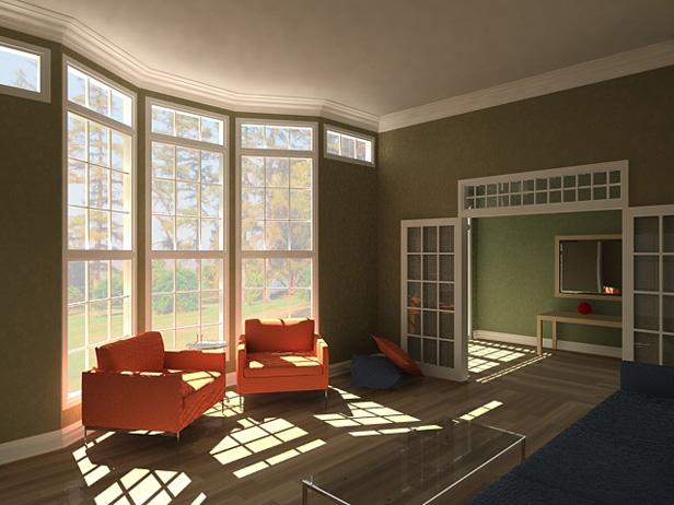
59 Distributed Ray Tracing Depth of Field Distribute rays over the circle of confusion

60 Depth of Field
 Ray tracing (global specular reflection) + Radiosity (global diffuse")
61 Radiosity Ray tracing Global illumination Radiosity specular reflection & specular refraction Highly realistic, particularly when the scene contains shiny objects A solution to diffuse interaction At the expense of dividing the environment into largish elements (constant illumination) Ray tracing (global specular reflection) + Radiosity (global diffuse reflection)
62 Radiosity Radiosity Defined as the energy per unit area leaving a surface patch per unit time The sum of the emitted and the reflected energy + = k k kj k j j j j j da F B R da E da B + = k jk k j j j F B R E B = + = n k jk k j j j F B R E B 1 k kj j jk A F A F = (reciprocal relationship) (dividing by ) da j j j k j jk A A A A F space surrounding in the hemispherical directions in all radiative energy leaving surface directly that strikes radiative energy leaving surface = = n n nn n n n n n n E E E B B B F R F R F R F R F R F R R F R F R F


63 Radiosity
64 Photon Mapping Radiosity Accurate display of global illumination effects for simple scenes More difficult to apply as the scene complexity increases Regarding rendering time and storage requirements Photon mapping Used for modeling global illumination in complex scenes Efficient and accurate Two-pass global illumination algorithm 1. Rays from the light source and rays from the camera are traced independently until some termination criterion is met 2. They are connected in a second step to produce a radiance value


65 Photon Mapping


66 Texture Mapping Pattern Mapping Map patterns of color onto geometric description of an object for adding detail to the object. umbrella, background, beach ball, beach blanket
, 0.0 s 1.0 T ( s, t), 0.0 s, t 1.0 T ( s, t, r), 0.0 s, t, r 1.")
67 Texture Pattern Separate texture space and screen space Linear texture pattern: Surface texture pattern: Volume texture pattern: Parametric texture mapping T ( s), 0.0 s 1.0 T ( s, t), 0.0 s, t 1.0 T ( s, t, r), 0.0 s, t, r 1.0 s t


 Inverse Scanning")
68 Texture Mapping Texture Space Texture- Surface Transformation Texture Scanning Object Space Viewing and Projection Transformation ( s, t) ( u, v, n) ( x, y) Inverse Scanning Image-Order Scanning Image Space
69 Texture Mapping Texture scanning Map from texture space to pixel space Disadv. A selected texture patch usually does not match up with pixel boundaries Calculations to determine the fractional area of pixel coverage Inverse scanning Map from pixel space to texture space Most commonly used method


70 Texture Mapping Inverse scanning Find pre-image of the current pixel in the texture space 1. Take the four pixel corner points 2. Invert the viewing and projection transformation 3. Invert the texture-surface transformation Object size decreases Pre-image of a pixel in texture space increases need anti-aliasing
 texels but we only select one of them to use in the pixel this kind of point sampling results in aliasing")
71 Texture Aliasing Simple texture application At each pixel we calculate the correct texture coordinate And retrieve the corresponding texel Can lead to nasty aliasing A pixel is mapped to several (fractional) texels but we only select one of them to use in the pixel this kind of point sampling results in aliasing
 Drawbacks Averaging covered texels can be very expensive")
72 Texture Aliasing Texture filtering Average all covered texels together Need to choose appropriate averaging method Reduce objectionable artifacts Very high frequency details just get smoothed over completely (e.g., gray on horizon) Drawbacks Averaging covered texels can be very expensive

73 Texture Aliasing pre-image pixel with pixel w/o anti-aliasing anti-aliasing pixel center


74 Texture Aliasing For efficiency, an image pyramid (MIP maps) multum in parvo, that is much on a small object Base of pyramid is the original image (level=0) Level 1: the image down-sampled by a factor of 2 Level 2: the image down-sampled by a factor of 4 Not too big: 4/3 the size of the original image

75 Antialiasing with MIP maps MIP maps Efficient averaging of large regions Each texel in upper level cover many base texels k k At level k, they are the average of 2 2 texels Can quickly assemble appropriate texels for averaging


76 Bump Mapping A method for modeling rough surface appearance E.g., Oranges, strawberries, and raisins Apply a perturbation function to the surface normal N = N + N Use the perturbed normal vector in the illumination calculations
Given: scene specification (object positions, optical properties p of the surface, viewer position, viewing direction, )
") Illumination and Shading Illumination and Shading Given: scene specification (object positions, optical properties p of the surface, viewer position, viewing direction, ) Find: intensity for each pixel
Illumination and Shading Illumination and Shading Given: scene specification (object positions, optical properties p of the surface, viewer position, viewing direction, ) Find: intensity for each pixel
Illumination and Shading
 llumination and Shading llumination and Shading Given: scene specification (object positions, optical properties of the surface, viewer position, viewing direction, ) Find: intensity for each pixel viewer
Computer Graphics. Illumination Models and Surface-Rendering Methods. Somsak Walairacht, Computer Engineering, KMITL
 Computer Graphics Chapter 10 llumination Models and Surface-Rendering Methods Somsak Walairacht, Computer Engineering, KMTL Outline Light Sources Surface Lighting Effects Basic llumination Models Polygon
Chapter 10. Surface-Rendering Methods. Somsak Walairacht, Computer Engineering, KMITL
 Computer Graphics Chapter 10 llumination Models and Surface-Rendering Methods Somsak Walairacht, Computer Engineering, KMTL 1 Outline Light Sources Surface Lighting Effects Basic llumination Models Polygon
Illumination and Shading
 Illumination and Shading Illumination (Lighting)! Model the interaction of light with surface points to determine their final color and brightness! The illumination can be computed either at vertices or
Comp 410/510 Computer Graphics. Spring Shading
 Comp 410/510 Computer Graphics Spring 2017 Shading Why we need shading Suppose we build a model of a sphere using many polygons and then color it using a fixed color. We get something like But we rather
CEng 477 Introduction to Computer Graphics Fall
 Illumination Models and Surface-Rendering Methods CEng 477 Introduction to Computer Graphics Fall 2007 2008 Illumination Models and Surface Rendering Methods In order to achieve realism in computer generated
Today we will start to look at illumination models in computer graphics
 1 llumination Today we will start to look at illumination models in computer graphics Why do we need illumination models? Different kinds lights Different kinds reflections Basic lighting model 2 Why Lighting?
Introduction to Computer Graphics 7. Shading
 Introduction to Computer Graphics 7. Shading National Chiao Tung Univ, Taiwan By: I-Chen Lin, Assistant Professor Textbook: Hearn and Baker, Computer Graphics, 3rd Ed., Prentice Hall Ref: E.Angel, Interactive
Computer Graphics. Shading. Based on slides by Dianna Xu, Bryn Mawr College
 Computer Graphics Shading Based on slides by Dianna Xu, Bryn Mawr College Image Synthesis and Shading Perception of 3D Objects Displays almost always 2 dimensional. Depth cues needed to restore the third
Reflection and Shading
 Reflection and Shading R. J. Renka Department of Computer Science & Engineering University of North Texas 10/19/2015 Light Sources Realistic rendering requires that we model the interaction between light
CPSC 314 LIGHTING AND SHADING
 CPSC 314 LIGHTING AND SHADING UGRAD.CS.UBC.CA/~CS314 slide credits: Mikhail Bessmeltsev et al 1 THE RENDERING PIPELINE Vertices and attributes Vertex Shader Modelview transform Per-vertex attributes Vertex
CS5620 Intro to Computer Graphics
 So Far wireframe hidden surfaces Next step 1 2 Light! Need to understand: How lighting works Types of lights Types of surfaces How shading works Shading algorithms What s Missing? Lighting vs. Shading
Topic 9: Lighting & Reflection models. Lighting & reflection The Phong reflection model diffuse component ambient component specular component
 Topic 9: Lighting & Reflection models Lighting & reflection The Phong reflection model diffuse component ambient component specular component Spot the differences Terminology Illumination The transport
Shading. Why we need shading. Scattering. Shading. Objectives
 Shading Why we need shading Objectives Learn to shade objects so their images appear three-dimensional Suppose we build a model of a sphere using many polygons and color it with glcolor. We get something
WHY WE NEED SHADING. Suppose we build a model of a sphere using many polygons and color it with glcolor. We get something like.
 LIGHTING 1 OUTLINE Learn to light/shade objects so their images appear three-dimensional Introduce the types of light-material interactions Build a simple reflection model---the Phong model--- that can
Topic 9: Lighting & Reflection models 9/10/2016. Spot the differences. Terminology. Two Components of Illumination. Ambient Light Source
 Topic 9: Lighting & Reflection models Lighting & reflection The Phong reflection model diffuse component ambient component specular component Spot the differences Terminology Illumination The transport
Illumination & Shading
 Illumination & Shading Goals Introduce the types of light-material interactions Build a simple reflection model---the Phong model--- that can be used with real time graphics hardware Why we need Illumination
Local Illumination. CMPT 361 Introduction to Computer Graphics Torsten Möller. Machiraju/Zhang/Möller
 Local Illumination CMPT 361 Introduction to Computer Graphics Torsten Möller Graphics Pipeline Hardware Modelling Transform Visibility Illumination + Shading Perception, Interaction Color Texture/ Realism
Illumination Models & Shading
 Illumination Models & Shading Lighting vs. Shading Lighting Interaction between materials and light sources Physics Shading Determining the color of a pixel Computer Graphics ZBuffer(Scene) PutColor(x,y,Col(P));
Lecture 15: Shading-I. CITS3003 Graphics & Animation
 Lecture 15: Shading-I CITS3003 Graphics & Animation E. Angel and D. Shreiner: Interactive Computer Graphics 6E Addison-Wesley 2012 Objectives Learn that with appropriate shading so objects appear as threedimensional
CS 325 Computer Graphics
 CS 325 Computer Graphics 04 / 02 / 2012 Instructor: Michael Eckmann Today s Topics Questions? Comments? Illumination modelling Ambient, Diffuse, Specular Reflection Surface Rendering / Shading models Flat
Illumination & Shading: Part 1
 Illumination & Shading: Part 1 Light Sources Empirical Illumination Shading Local vs Global Illumination Lecture 10 Comp 236 Spring 2005 Computer Graphics Jargon: Illumination Models Illumination - the
Recollection. Models Pixels. Model transformation Viewport transformation Clipping Rasterization Texturing + Lights & shadows
 Recollection Models Pixels Model transformation Viewport transformation Clipping Rasterization Texturing + Lights & shadows Can be computed in different stages 1 So far we came to Geometry model 3 Surface
Announcements. Written Assignment 2 out (due March 8) Computer Graphics
 Computer Graphics") Announcements Written Assignment 2 out (due March 8) 1 Advanced Ray Tracing (Recursive) Ray Tracing Antialiasing Motion Blur Distribution Ray Tracing Ray Tracing and Radiosity Assumptions Simple shading
Announcements Written Assignment 2 out (due March 8) 1 Advanced Ray Tracing (Recursive) Ray Tracing Antialiasing Motion Blur Distribution Ray Tracing Ray Tracing and Radiosity Assumptions Simple shading
Computer Graphics. Illumination and Shading
 () Illumination and Shading Dr. Ayman Eldeib Lighting So given a 3-D triangle and a 3-D viewpoint, we can set the right pixels But what color should those pixels be? If we re attempting to create a realistic
Shading I Computer Graphics I, Fall 2008
 Shading I 1 Objectives Learn to shade objects ==> images appear threedimensional Introduce types of light-material interactions Build simple reflection model Phong model Can be used with real time graphics
Lighting and Shading Computer Graphics I Lecture 7. Light Sources Phong Illumination Model Normal Vectors [Angel, Ch
 15-462 Computer Graphics I Lecture 7 Lighting and Shading February 12, 2002 Frank Pfenning Carnegie Mellon University http://www.cs.cmu.edu/~fp/courses/graphics/ Light Sources Phong Illumination Model
Computer Graphics (CS 4731) Lecture 16: Lighting, Shading and Materials (Part 1)
 Lecture 16: Lighting, Shading and Materials (Part 1)") Computer Graphics (CS 4731) Lecture 16: Lighting, Shading and Materials (Part 1) Prof Emmanuel Agu Computer Science Dept. Worcester Polytechnic Institute (WPI) Why do we need Lighting & shading? Sphere
Computer Graphics (CS 4731) Lecture 16: Lighting, Shading and Materials (Part 1) Prof Emmanuel Agu Computer Science Dept. Worcester Polytechnic Institute (WPI) Why do we need Lighting & shading? Sphere
So far, we have considered only local models of illumination; they only account for incident light coming directly from the light sources.
 11 11.1 Basics So far, we have considered only local models of illumination; they only account for incident light coming directly from the light sources. Global models include incident light that arrives
CS Illumination and Shading. Slide 1
 CS 112 - Illumination and Shading Slide 1 Illumination/Lighting Interaction between light and surfaces Physics of optics and thermal radiation Very complex: Light bounces off several surface before reaching
Computer Graphics (CS 543) Lecture 7b: Intro to lighting, Shading and Materials + Phong Lighting Model
 Lecture 7b: Intro to lighting, Shading and Materials + Phong Lighting Model") Computer Graphics (CS 543) Lecture 7b: Intro to lighting, Shading and Materials + Phong Lighting Model Prof Emmanuel Agu Computer Science Dept. Worcester Polytechnic Institute (WPI) Why do we need Lighting
Computer Graphics (CS 543) Lecture 7b: Intro to lighting, Shading and Materials + Phong Lighting Model Prof Emmanuel Agu Computer Science Dept. Worcester Polytechnic Institute (WPI) Why do we need Lighting
Computer Graphics. Lecture 13. Global Illumination 1: Ray Tracing and Radiosity. Taku Komura
 Computer Graphics Lecture 13 Global Illumination 1: Ray Tracing and Radiosity Taku Komura 1 Rendering techniques Can be classified as Local Illumination techniques Global Illumination techniques Local
Surface Rendering Methods
 Surface Rendering Methods 6 th Week, 2008 Sun-Jeong Kim Polygon Rendering Methods Determining the surface intensity at every projected pixel position using an illumination model Light-material interactions
I have a meeting with Peter Lee and Bob Cosgrove on Wednesday to discuss the future of the cluster. Computer Graphics
 Announcements Assignment 4 will be out later today Problem Set 3 is due today or tomorrow by 9am in my mail box (4 th floor NSH) How are the machines working out? I have a meeting with Peter Lee and Bob
Overview. Shading. Shading. Why we need shading. Shading Light-material interactions Phong model Shading polygons Shading in OpenGL
 Overview Shading Shading Light-material interactions Phong model Shading polygons Shading in OpenGL Why we need shading Suppose we build a model of a sphere using many polygons and color it with glcolor.
w Foley, Section16.1 Reading
 Shading w Foley, Section16.1 Reading Introduction So far, we ve talked exclusively about geometry. w What is the shape of an object? w How do I place it in a virtual 3D space? w How do I know which pixels
surface: reflectance transparency, opacity, translucency orientation illumination: location intensity wavelength point-source, diffuse source
 walters@buffalo.edu CSE 480/580 Lecture 18 Slide 1 Illumination and Shading Light reflected from nonluminous objects depends on: surface: reflectance transparency, opacity, translucency orientation illumination:
Objectives. Introduce Phong model Introduce modified Phong model Consider computation of required vectors Discuss polygonal shading.
 Shading II 1 Objectives Introduce Phong model Introduce modified Phong model Consider computation of required vectors Discuss polygonal shading Flat Smooth Gouraud 2 Phong Lighting Model A simple model
Three-Dimensional Graphics V. Guoying Zhao 1 / 55
 Computer Graphics Three-Dimensional Graphics V Guoying Zhao 1 / 55 Shading Guoying Zhao 2 / 55 Objectives Learn to shade objects so their images appear three-dimensional Introduce the types of light-material
9. Illumination and Shading
 9. Illumination and Shading Approaches for visual realism: - Remove hidden surfaces - Shade visible surfaces and reproduce shadows - Reproduce surface properties Texture Degree of transparency Roughness,
Illumination in Computer Graphics
 Illumination in Computer Graphics Ann McNamara Illumination in Computer Graphics Definition of light sources. Analysis of interaction between light and objects in a scene. Rendering images that are faithful
Virtual Reality for Human Computer Interaction
 Virtual Reality for Human Computer Interaction Appearance: Lighting Representation of Light and Color Do we need to represent all I! to represent a color C(I)? No we can approximate using a three-color
Lighting and Reflectance COS 426
 ighting and Reflectance COS 426 Ray Casting R2mage *RayCast(R3Scene *scene, int width, int height) { R2mage *image = new R2mage(width, height); for (int i = 0; i < width; i++) { for (int j = 0; j < height;
Today. Global illumination. Shading. Interactive applications. Rendering pipeline. Computergrafik. Shading Introduction Local shading models
 Computergrafik Thomas Buchberger, Matthias Zwicker Universität Bern Herbst 2008 Today Introduction Local shading models Light sources strategies Compute interaction of light with surfaces Requires simulation
Illumination Model. The governing principles for computing the. Apply the lighting model at a set of points across the entire surface.
 Illumination and Shading Illumination (Lighting) Model the interaction of light with surface points to determine their final color and brightness OpenGL computes illumination at vertices illumination Shading
Illumination and Shading
 Illumination and Shading Computer Graphics COMP 770 (236) Spring 2007 Instructor: Brandon Lloyd 2/14/07 1 From last time Texture mapping overview notation wrapping Perspective-correct interpolation Texture
CSE 167: Introduction to Computer Graphics Lecture #6: Lights. Jürgen P. Schulze, Ph.D. University of California, San Diego Fall Quarter 2016
 CSE 167: Introduction to Computer Graphics Lecture #6: Lights Jürgen P. Schulze, Ph.D. University of California, San Diego Fall Quarter 2016 Announcements Thursday in class: midterm #1 Closed book Material
Illumination. Courtesy of Adam Finkelstein, Princeton University
 llumination Courtesy of Adam Finkelstein, Princeton University Ray Casting mage RayCast(Camera camera, Scene scene, int width, int height) { mage image = new mage(width, height); for (int i = 0; i < width;
Today. Global illumination. Shading. Interactive applications. Rendering pipeline. Computergrafik. Shading Introduction Local shading models
 Computergrafik Matthias Zwicker Universität Bern Herbst 2009 Today Introduction Local shading models Light sources strategies Compute interaction of light with surfaces Requires simulation of physics Global
Computer Graphics. Lecture 10. Global Illumination 1: Ray Tracing and Radiosity. Taku Komura 12/03/15
 Computer Graphics Lecture 10 Global Illumination 1: Ray Tracing and Radiosity Taku Komura 1 Rendering techniques Can be classified as Local Illumination techniques Global Illumination techniques Local
Computer Graphics. Illumination and Shading
 Rendering Pipeline modelling of geometry transformation into world coordinates placement of cameras and light sources transformation into camera coordinates backface culling projection clipping w.r.t.
Illumination and Shading
 Illumination and Shading Illumination (Lighting) Model the interaction of light with surface points to determine their final color and brightness OpenGL computes illumination at vertices illumination Shading
Rendering. Illumination Model. Wireframe rendering simple, ambiguous Color filling flat without any 3D information
 llumination Model Wireframe rendering simple, ambiguous Color filling flat without any 3D information Requires modeling interaction of light with the object/surface to have a different color (shade in
Topic 12: Texture Mapping. Motivation Sources of texture Texture coordinates Bump mapping, mip-mapping & env mapping
 Topic 12: Texture Mapping Motivation Sources of texture Texture coordinates Bump mapping, mip-mapping & env mapping Texture sources: Photographs Texture sources: Procedural Texture sources: Solid textures
C O M P U T E R G R A P H I C S. Computer Graphics. Three-Dimensional Graphics V. Guoying Zhao 1 / 65
 Computer Graphics Three-Dimensional Graphics V Guoying Zhao 1 / 65 Shading Guoying Zhao 2 / 65 Objectives Learn to shade objects so their images appear three-dimensional Introduce the types of light-material
University of Victoria CSC 305 Shading. Brian Wyvill 2016
 University of Victoria CSC 305 Shading Brian Wyvill 2016 The illuminating Hemisphere Energy and Intensity Energy is the intensity integrated over the solid angle through which it acts. Intensity is not
Introduction to Computer Graphics. Farhana Bandukwala, PhD Lecture 14: Light Interacting with Surfaces
 Introduction to Computer Graphics Farhana Bandukwala, PhD Lecture 14: Light Interacting with Surfaces Outline Computational tools Reflection models Polygon shading Computation tools Surface normals Vector
CS770/870 Spring 2017 Color and Shading
 Preview CS770/870 Spring 2017 Color and Shading Related material Cunningham: Ch 5 Hill and Kelley: Ch. 8 Angel 5e: 6.1-6.8 Angel 6e: 5.1-5.5 Making the scene more realistic Color models representing the
Illumination & Shading I
 CS 543: Computer Graphics Illumination & Shading I Robert W. Lindeman Associate Professor Interactive Media & Game Development Department of Computer Science Worcester Polytechnic Institute gogo@wpi.edu
Raytracing. COSC 4328/5327 Scott A. King
 Raytracing COSC 4328/5327 Scott A. King Basic Ray Casting Method pixels in screen Shoot ray p from the eye through the pixel. Find closest ray-object intersection. Get color at intersection Basic Ray Casting
Lighting and Shading
 Lighting and Shading Today: Local Illumination Solving the rendering equation is too expensive First do local illumination Then hack in reflections and shadows Local Shading: Notation light intensity in,
ECS 175 COMPUTER GRAPHICS. Ken Joy.! Winter 2014
 ECS 175 COMPUTER GRAPHICS Ken Joy Winter 2014 Shading To be able to model shading, we simplify Uniform Media no scattering of light Opaque Objects No Interreflection Point Light Sources RGB Color (eliminating
Topic 11: Texture Mapping 11/13/2017. Texture sources: Solid textures. Texture sources: Synthesized
 Topic 11: Texture Mapping Motivation Sources of texture Texture coordinates Bump mapping, mip mapping & env mapping Texture sources: Photographs Texture sources: Procedural Texture sources: Solid textures
CMSC427 Shading Intro. Credit: slides from Dr. Zwicker
 CMSC427 Shading Intro Credit: slides from Dr. Zwicker 2 Today Shading Introduction Radiometry & BRDFs Local shading models Light sources Shading strategies Shading Compute interaction of light with surfaces
CENG 477 Introduction to Computer Graphics. Ray Tracing: Shading
 CENG 477 Introduction to Computer Graphics Ray Tracing: Shading Last Week Until now we learned: How to create the primary rays from the given camera and image plane parameters How to intersect these rays
CS130 : Computer Graphics Lecture 8: Lighting and Shading. Tamar Shinar Computer Science & Engineering UC Riverside
 CS130 : Computer Graphics Lecture 8: Lighting and Shading Tamar Shinar Computer Science & Engineering UC Riverside Why we need shading Suppose we build a model of a sphere using many polygons and color
Visualisatie BMT. Rendering. Arjan Kok
 Visualisatie BMT Rendering Arjan Kok a.j.f.kok@tue.nl 1 Lecture overview Color Rendering Illumination 2 Visualization pipeline Raw Data Data Enrichment/Enhancement Derived Data Visualization Mapping Abstract
Homework #2. Shading, Ray Tracing, and Texture Mapping
 Computer Graphics Prof. Brian Curless CSE 457 Spring 2000 Homework #2 Shading, Ray Tracing, and Texture Mapping Prepared by: Doug Johnson, Maya Widyasari, and Brian Curless Assigned: Monday, May 8, 2000
Topic 11: Texture Mapping 10/21/2015. Photographs. Solid textures. Procedural
 Topic 11: Texture Mapping Motivation Sources of texture Texture coordinates Bump mapping, mip mapping & env mapping Topic 11: Photographs Texture Mapping Motivation Sources of texture Texture coordinates
CS 4600 Fall Utah School of Computing
 Lighting CS 4600 Fall 2015 Utah School of Computing Objectives Learn to shade objects so their images appear three-dimensional Introduce the types of light-material interactions Build a simple reflection
COMP371 COMPUTER GRAPHICS
 COMP371 COMPUTER GRAPHICS SESSION 15 RAY TRACING 1 Announcements Programming Assignment 3 out today - overview @ end of the class Ray Tracing 2 Lecture Overview Review of last class Ray Tracing 3 Local
Simple Lighting/Illumination Models
 Simple Lighting/Illumination Models Scene rendered using direct lighting only Photograph Scene rendered using a physically-based global illumination model with manual tuning of colors (Frederic Drago and
EECS 487: Interactive Computer Graphics
 Ray Tracing EECS 487: Interactive Computer Graphics Lecture 29: Distributed Ray Tracing Introduction and context ray casting Recursive ray tracing shadows reflection refraction Ray tracing implementation
Lighting Models. CS116B Chris Pollett Mar 21, 2004.
 Lighting Models CS116B Chris Pollett Mar 21, 2004. Outline Overview Light Sources Surface Lighting Effect Basic Illumination Models Overview An illumination model (lighting model) is used to calculate
CSCI 4620/8626. Computer Graphics Illumination Models and Surface Rendering Methods (Chapter 17)
") CSCI 4620/8626 Computer Graphics Illumination Models and Surface Rendering Methods (Chapter 17) Last update: 2016-04-19 Realism! Realistic displays of a scene use! Perspective projections of objects! Application
CSCI 4620/8626 Computer Graphics Illumination Models and Surface Rendering Methods (Chapter 17) Last update: 2016-04-19 Realism! Realistic displays of a scene use! Perspective projections of objects! Application
CSE 681 Illumination and Phong Shading
 CSE 681 Illumination and Phong Shading Physics tells us What is Light? We don t see objects, we see light reflected off of objects Light is a particle and a wave The frequency of light What is Color? Our
OpenGl Pipeline. triangles, lines, points, images. Per-vertex ops. Primitive assembly. Texturing. Rasterization. Per-fragment ops.
 OpenGl Pipeline Individual Vertices Transformed Vertices Commands Processor Per-vertex ops Primitive assembly triangles, lines, points, images Primitives Fragments Rasterization Texturing Per-fragment
03 RENDERING PART TWO
 03 RENDERING PART TWO WHAT WE HAVE SO FAR: GEOMETRY AFTER TRANSFORMATION AND SOME BASIC CLIPPING / CULLING TEXTURES AND MAPPING MATERIAL VISUALLY DISTINGUISHES 2 OBJECTS WITH IDENTICAL GEOMETRY FOR NOW,
CS580: Ray Tracing. Sung-Eui Yoon ( 윤성의 ) Course URL:
 Course URL:") CS580: Ray Tracing Sung-Eui Yoon ( 윤성의 ) Course URL: http://sglab.kaist.ac.kr/~sungeui/gcg/ Recursive Ray Casting Gained popularity in when Turner Whitted (1980) recognized that recursive ray casting could
CS580: Ray Tracing Sung-Eui Yoon ( 윤성의 ) Course URL: http://sglab.kaist.ac.kr/~sungeui/gcg/ Recursive Ray Casting Gained popularity in when Turner Whitted (1980) recognized that recursive ray casting could
Shading Intro. Shading & Lighting. Light and Matter. Light and Matter
 Shading Intro Shading & Lighting Move from flat to 3-D models Orthographic view of sphere was uniformly color, thus, a flat circle A circular shape with many gradations or shades of color Courtesy of Vincent
Lighting. Figure 10.1
 We have learned to build three-dimensional graphical models and to display them. However, if you render one of our models, you might be disappointed to see images that look flat and thus fail to show the
Ray Tracing. CSCI 420 Computer Graphics Lecture 15. Ray Casting Shadow Rays Reflection and Transmission [Ch ]
![Ray Tracing. CSCI 420 Computer Graphics Lecture 15. Ray Casting Shadow Rays Reflection and Transmission [Ch ]](/thumbs/78/78594982.jpg "Ray Tracing. CSCI 420 Computer Graphics Lecture 15. Ray Casting Shadow Rays Reflection and Transmission [Ch ]") CSCI 420 Computer Graphics Lecture 15 Ray Tracing Ray Casting Shadow Rays Reflection and Transmission [Ch. 13.2-13.3] Jernej Barbic University of Southern California 1 Local Illumination Object illuminations
CSCI 420 Computer Graphics Lecture 15 Ray Tracing Ray Casting Shadow Rays Reflection and Transmission [Ch. 13.2-13.3] Jernej Barbic University of Southern California 1 Local Illumination Object illuminations
Local vs. Global Illumination & Radiosity
 Last Time? Local vs. Global Illumination & Radiosity Ray Casting & Ray-Object Intersection Recursive Ray Tracing Distributed Ray Tracing An early application of radiative heat transfer in stables. Reading
Computer Vision Systems. Viewing Systems Projections Illuminations Rendering Culling and Clipping Implementations
 Computer Vision Systems Viewing Systems Projections Illuminations Rendering Culling and Clipping Implementations Viewing Systems Viewing Transformation Projective Transformation 2D Computer Graphics Devices
Graphics for VEs. Ruth Aylett
 Graphics for VEs Ruth Aylett Overview VE Software Graphics for VEs The graphics pipeline Projections Lighting Shading VR software Two main types of software used: off-line authoring or modelling packages
Ray-Tracing. Misha Kazhdan
 Ray-Tracing Misha Kazhdan Ray-Tracing In graphics, we often represent the surface of a 3D shape by a set of triangles. Goal: Ray-Tracing Take a collection of triangles representing a 3D scene and render
Color and Light CSCI 4229/5229 Computer Graphics Fall 2016
 Color and Light CSCI 4229/5229 Computer Graphics Fall 2016 Solar Spectrum Human Trichromatic Color Perception Color Blindness Present to some degree in 8% of males and about 0.5% of females due to mutation
Today s class. Simple shadows Shading Lighting in OpenGL. Informationsteknologi. Wednesday, November 21, 2007 Computer Graphics - Class 10 1
 Today s class Simple shadows Shading Lighting in OpenGL Wednesday, November 21, 27 Computer Graphics - Class 1 1 Simple shadows Simple shadows can be gotten by using projection matrices Consider a light
Global Illumination. CSCI 420 Computer Graphics Lecture 18. BRDFs Raytracing and Radiosity Subsurface Scattering Photon Mapping [Ch
 CSCI 420 Computer Graphics Lecture 18 Global Illumination Jernej Barbic University of Southern California BRDFs Raytracing and Radiosity Subsurface Scattering Photon Mapping [Ch. 13.4-13.5] 1 Global Illumination
Shading, Advanced Rendering. Week 7, Wed Feb 28
 University of British Columbia CPSC 314 Computer Graphics Jan-Apr 2007 Tamara Munzner Shading, Advanced Rendering Week 7, Wed Feb 28 http://www.ugrad.cs.ubc.ca/~cs314/vjan2007 Reading for Today and Tomorrow
Visual cues to 3D geometry. Light Reflection and Advanced Shading. Shading. Recognizing materials. size (perspective) occlusion shading
 occlusion shading") Visual cues to 3D geometry Light Reflection and Advanced Shading size (perspective) occlusion shading CS 4620 Lecture 17 1 2 Shading Recognizing materials Variation in observed color across an object strongly
Visual cues to 3D geometry Light Reflection and Advanced Shading size (perspective) occlusion shading CS 4620 Lecture 17 1 2 Shading Recognizing materials Variation in observed color across an object strongly
CS Computer Graphics: Illumination and Shading I
 CS 543 - Computer Graphics: Illumination and Shading I by Robert W. Lindeman gogo@wpi.edu (with help from Emmanuel Agu ;-) Illumination and Shading Problem: Model light/surface point interactions to determine
CS Computer Graphics: Illumination and Shading I
 CS 543 - Computer Graphics: Illumination and Shading I by Robert W. Lindeman gogo@wpi.edu (with help from Emmanuel Agu ;-) Illumination and Shading Problem: Model light/surface point interactions to determine
CPSC / Illumination and Shading
 CPSC 599.64 / 601.64 Rendering Pipeline usually in one step modelling of geometry transformation into world coordinate system placement of cameras and light sources transformation into camera coordinate
Why we need shading?
 Why we need shading? Suppose we build a model of a sphere using many polygons and color it with glcolor. We get something like But we want Light-material interactions cause each point to have a different
Global Illumination. Global Illumination. Direct Illumination vs. Global Illumination. Indirect Illumination. Soft Shadows.
 CSCI 420 Computer Graphics Lecture 18 Global Illumination Jernej Barbic University of Southern California BRDFs Raytracing and Radiosity Subsurface Scattering Photon Mapping [Angel Ch. 11] 1 Global Illumination
Illumination. Michael Kazhdan ( /657) HB Ch. 14.1, 14.2 FvDFH 16.1, 16.2
 HB Ch. 14.1, 14.2 FvDFH 16.1, 16.2") Illumination Michael Kazhdan (601.457/657) HB Ch. 14.1, 14.2 FvDFH 16.1, 16.2 Ray Casting Image RayCast(Camera camera, Scene scene, int width, int height) { Image image = new Image(width, height); for
Illumination Michael Kazhdan (601.457/657) HB Ch. 14.1, 14.2 FvDFH 16.1, 16.2 Ray Casting Image RayCast(Camera camera, Scene scene, int width, int height) { Image image = new Image(width, height); for
6. Illumination, Lighting
 Jorg s Graphics Lecture Notes 6. Illumination, Lighting 1 6. Illumination, Lighting No ray tracing in OpenGL! ray tracing: direct paths COP interreflection: soft shadows, color bleeding. umbra, penumbra,
Global Illumination. Global Illumination. Direct Illumination vs. Global Illumination. Indirect Illumination. Soft Shadows.
 CSCI 480 Computer Graphics Lecture 18 Global Illumination BRDFs Raytracing and Radiosity Subsurface Scattering Photon Mapping [Ch. 13.4-13.5] March 28, 2012 Jernej Barbic University of Southern California