CFD design tool for industrial applications
|
|
|
- Tiffany Oliver
- 6 years ago
- Views:
Transcription
1 Sixth LACCEI International Latin American and Caribbean Conference for Engineering and Technology (LACCEI 2008) Partnering to Success: Engineering, Education, Research and Development June 4 June , Tegucigalpa, Honduras. CFD design tool for industrial applications Geanette Polanco Simón BolívarUniversity, Caracas, Venezuela, gpolanco@usb.ve Arne Holdo Coventry University, Coventry, U.K., aa4083@coventry.ac.uk Julio Longa Simón Bolívar University, Caracas, Venezuela, longag@usb.ve ABSTRACT Geometry with sharp edges generally produces turbulent in the flow with high levels of noise generation that affects the flow characteristic. Simulations permit to establish predictions about the reductions of undesirable effects in the operational conditions of industrial processes. The example shown in this work consists of a generic air knife normally used in drying systems. Varying the geometry of a specimen in the simulation shows that a smoother contour reduces the turbulence level of the flow and its relational effects. This result suggests that the new design of air knives may include aerodynamic considerations to improve its performance. Keywords: CFD, air knife, design tool 1. INTRODUCTION Drying systems have an important role in a wide range of industrial processes. The efficiency covers the performance of each element inside. The air knife is the device most important in the drying line with the most possibility to be enhanced, (Paxton, 2008). Normally, the air knives have a large body with different entries and one long a thin exit, (Turbotech, 2008). This generates a complex flow inside as well as a complex et flow downstream the exit. Both situations will be examined by computational means using a 3D approach for the internal flow and a 2D approach for the external flow. There are different cross sections with different dimensions. This obeys meanly to manufactures and the processes used to build them, see Figure 1. The geometry studied in this work corresponds to one of the simplified cross section, as shown in Figure 2. The entrance is assumed to be a circular cross section of diameter of 80 mm and 20 mm long, located at one end of the body of the air-knife. The dimension of the air-knife body is 800 mm. WE1-1
, Air Knives (2008),")


2 Figure 1: Common geometries of a air knives. Source: Sonic (2008), Air Knives (2008), Direct industry (2008) and Paxton (2008) Figure 2: Simplified geometry. Named hereafter as original geometry 2. THE MODEL TIME DEPENDENCY The analysis is steady-state. No transient effects are taking into account for in any of the models. THE FLUID The fluid defined for the simulation was standard air, under the assumption of the uncompressible air flow. THE MESH WE1-2
3 Due to the high aspect ration of the nozzle located at the discharge location of the air-knife, a demanding mesh is needed to achieve low aspect ratios of the individual element of the domain. The characteristics of the grid used correspond to a structure non-orthogonal mesh in all cases. In order to despite any dependency of the result from the mesh used, a mesh sensibility study was also performed. TEST CONDITIONS The inlet velocity (54 m/s) is perpendicular to the inlet at the inlet depicting the fact of any change in direction of the flow due to the air supply system BOUNDARY CONDITIONS Boundary conditions for the internal body of the air-knife were assumed to be of constant velocity at the endentrance of the air-knife and outflow at the gap of the nozzle. For the external study, a constant flow velocity in the gap and outflow in the borders around of the domain were selected. TURBULENCE In order to model the turbulent processes, the k-epsilon RNG and standard k-epsilon model were selected, for both internal and external flow of the air-knife respectively. The industrial standard is the two-equation model which is an eddy-viscosity type model based on time averaged Navier-Stokes equations, which are sometimes termed the Reynolds Averaged Navier-Stokes (RANS) equations. The RNG k-epsilon turbulence model is a modification of the standard k-epsilon turbulence models, and the difference between these two models appears in the epsilon equation. The kinetic energy equations are identical. The RNG model is normally used in cases with flow close to walls or flow with recirculation zones, (Bird, 1966). 3. GOVERNING EQUATIONS CFD is based on the numerical solution to the governing equations of fluid flow that express the conservation of mass, momentum and energy, (Launder and Spalding, 1974). The energy equation is not included in this work due to the assumption of incompressible flow. For a general 3D fluid the governing equations are: (Mass) (Momentum) where (,, k = 1,2,3) ρ + t ( ρu ) x ( ρu ) ( ρu U ) t + i x i = S m P = x U i + μ x i x U + x i ρuiu + S i and U = Components of the mean velocity in the x direction, u = Components of the fluctuating velocity in the x direction, h = Mean static enthalpy, h ' = Fluctuating static enthalpy, P = Pressure, ρ = Density, μ = Dynamic Viscosity, S = Source terms for mass (e.g. condensation, evaporation), m S = Source terms for momentum (e.g. body forces, buoyancy forces) and ρu u i = Turbulent Stresses. U U (1) (2) 4. RESULTS A selection of results obtained from the CFD calculation of each of the models is presented below: INTERNAL FLOW WE1-3


4 ORIGINAL GEOMETRY Figure 3: Contours of the velocity magnitude (m/s) for three different cross sections Figure 4: Contours of the velocity magnitude (m/s) for three different cross sections combined with a centre plane of the air-knife WE1-4
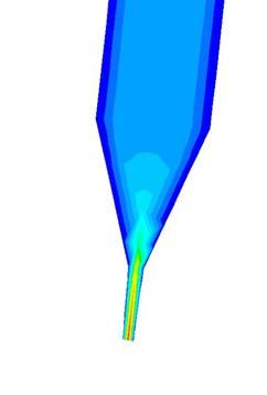
 Detail of the contours of the velocity magnitude at the exit of the nozzle Figure 6: Contours of the turbulence kinetic energy")
 at a centre plane of the air-knife body b) Detail of the close end of the body c) Detail of the open end of the body")

5 Figure 5: a) Contours of the velocity magnitude (m/s) at a cross section located at 0.5 m from the exit and the plane mesh. b) Detail of the contours of the velocity magnitude at the exit of the nozzle Figure 6: Contours of the turbulence kinetic energy (m 2 /s 2 ) at a cross section located at the centre of the air-knife body Figure 7: a) Contours of the turbulence kinetic energy (m 2 /s 2 ) at a centre plane of the air-knife body b) Detail of the close end of the body c) Detail of the open end of the body THE ENHANCED GEOMETRY After performing the simulation of the current model, a new geometry was proposed, based on smoothing the shape, but keeping the dimensions of the exit gap and the diameter of the main body of the air-knife, as can be seen in Figure17. WE1-5


6 Figure 8: Proposed internal domain of the air-knife body With the new geometry for the internal shape of the air-knife, new meshes were created and tested. The mesh aspect ratio in the gap is about of 2.35, whilst in the top is about 3.5. Figure 9: Contours of the velocity magnitude (m/s) for a cross section located at the centre of the air-knife body WE1-6
 at a cross section located at the")


7 Figure 10: Contours of the turbulence kinetic energy (m 2 /s 2 ) a) b) Figure 11: Contours of the turbulence kinetic energy (m 2 /s 2 ) at a cross section located at the centre of the air-knife body b) Detail at the bottom of the geometry, at the exit of the nozzle EXTERNAL FLOW THE ORIGINAL GEOMETRY The study of the air entrainment around of the body of the air-knife was performed using a 2D approach. It is important to observe the behavior of the flow around the solid shape and the impact of it on the turbulence. WE1-7


8 Figure 12: Plane mesh at the external part of the nozzle The entrainment has a large effect on the momentum conservation of the et, as it brings the energy necessary to keep the momentum constant in any cross section. In addition, to this condition it is known that any fluctuation or disturbance present in the surrounding will affect the characteristics of the et boundary, so, in the absence of a smooth shape, the entrainment tends to be very disturbed and then the et boundaries far from the nozzle makes a form of flapping motions. Figure 13: Contours of the turbulence kinetic energy (m 2 /s 2 ) around and downstream of the exit of the nozzle, for longer domain THE ENHANCED GEOMETRY The proposed geometry for the external part of the air-knife consists of the creation of a new curve, which substitute the whole external shape of the nozzle and the connection with the cylindered body. This curve allows a smoother connection between the external body and et. WE1-8
 downstream of the exit of the nozzle,")
 around and downstream of the exit of the nozzle, for longer domain 5.")
9 Figure 14: Plane mesh at the external part of the nozzle, for the proposed geometry Figure 15: Contours of the velocity magnitude (m/s) downstream of the exit of the nozzle, for the proposed external shape Figure 16: Contours of the turbulence kinetic energy (m 2 /s 2 ) around and downstream of the exit of the nozzle, for longer domain 5. DISCUSSIONS WE1-9
10 From the observation of the Figure 1 to 11, it can be discussed that no impinged et is observed at the opposite end of the air-knife body, which means the actual length is enough to distribute most of the kinetic energy at the inlet inside the body toward the nozzle exit. The velocity profile obtained allows the identification of slower zones close to the walls and toward to the opposite end of the body of the air-knife. No maor recirculation in the transversal cross section along the axis is presented. The new proposed internal shape produces a more natural flow of air inside the body of the air-knife. The velocity level achieved at the exit shape is almost the same for the both geometries. The production of turbulent kinetic energy, the dissipation rate and the turbulent intensity for the proposed internal shape were reduced in all cases respect to the original geometry. The et velocity contours at the exit of the nozzle produces by its interaction with the external shape of the airknife, see Figures 13. The improved shape helps to reduce the perturbations in the surroundings and consequently it helps to obtain a more stable et, as shown in Figures 15 and CONCLUSIONS The use of CFD as a design tool allows showing the influence of the aerodynamic surface on the flow characteristic. Particularly in the case of an industrial device such as an air knife, this influence on internal and external flow configuration enhances the turbulent phenomenon presented, and therefore the design of new air knife must consider this aspect as a very important to improve the overall performance of the air knife and the whole drying system. The testing capability of new designs using CFD is an unlimited resource. REFERENCES Air Knives (2008), April, 2008 Bird, R.B., Stewart, W.E., and Lightfoot, E.N. (1966). Transport Phenomena. John Wiley & Sons, New York. Direct industry (2008), Launder, B.E. and Spalding, D.B. (1974), Lectures in mathematical models of turbulence. Academic Press, New Paxton (2008), April, 2008 Sonic (2008), April, 2008 Turbotech, (2008). April, 2008 Authorization and Disclaimer Authors authorize LACCEI to publish the paper in the conference proceedings. Neither LACCEI nor the editors are responsible either for the content or for the implications of what is expressed in the paper. WE1-10
ANSYS AIM Tutorial Turbulent Flow Over a Backward Facing Step
 ANSYS AIM Tutorial Turbulent Flow Over a Backward Facing Step Author(s): Sebastian Vecchi, ANSYS Created using ANSYS AIM 18.1 Problem Specification Pre-Analysis & Start Up Governing Equation Start-Up Geometry
CFD Analysis of a Fully Developed Turbulent Flow in a Pipe with a Constriction and an Obstacle
 CFD Analysis of a Fully Developed Turbulent Flow in a Pipe with a Constriction and an Obstacle C, Diyoke Mechanical Engineering Department Enugu State University of Science & Tech. Enugu, Nigeria U, Ngwaka
Simulation of Turbulent Axisymmetric Waterjet Using Computational Fluid Dynamics (CFD)
") Simulation of Turbulent Axisymmetric Waterjet Using Computational Fluid Dynamics (CFD) PhD. Eng. Nicolae MEDAN 1 1 Technical University Cluj-Napoca, North University Center Baia Mare, Nicolae.Medan@cunbm.utcluj.ro
Simulation of Turbulent Axisymmetric Waterjet Using Computational Fluid Dynamics (CFD) PhD. Eng. Nicolae MEDAN 1 1 Technical University Cluj-Napoca, North University Center Baia Mare, Nicolae.Medan@cunbm.utcluj.ro
Non-Newtonian Transitional Flow in an Eccentric Annulus
 Tutorial 8. Non-Newtonian Transitional Flow in an Eccentric Annulus Introduction The purpose of this tutorial is to illustrate the setup and solution of a 3D, turbulent flow of a non-newtonian fluid. Turbulent
Simulation of Flow Development in a Pipe
 Tutorial 4. Simulation of Flow Development in a Pipe Introduction The purpose of this tutorial is to illustrate the setup and solution of a 3D turbulent fluid flow in a pipe. The pipe networks are common
Strömningslära Fluid Dynamics. Computer laboratories using COMSOL v4.4
 UMEÅ UNIVERSITY Department of Physics Claude Dion Olexii Iukhymenko May 15, 2015 Strömningslära Fluid Dynamics (5FY144) Computer laboratories using COMSOL v4.4!! Report requirements Computer labs must
MASSACHUSETTS INSTITUTE OF TECHNOLOGY. Analyzing wind flow around the square plate using ADINA Project. Ankur Bajoria
 MASSACHUSETTS INSTITUTE OF TECHNOLOGY Analyzing wind flow around the square plate using ADINA 2.094 - Project Ankur Bajoria May 1, 2008 Acknowledgement I would like to thank ADINA R & D, Inc for the full
COMPUTATIONAL FLUID DYNAMICS ANALYSIS OF ORIFICE PLATE METERING SITUATIONS UNDER ABNORMAL CONFIGURATIONS
 COMPUTATIONAL FLUID DYNAMICS ANALYSIS OF ORIFICE PLATE METERING SITUATIONS UNDER ABNORMAL CONFIGURATIONS Dr W. Malalasekera Version 3.0 August 2013 1 COMPUTATIONAL FLUID DYNAMICS ANALYSIS OF ORIFICE PLATE
Calculate a solution using the pressure-based coupled solver.
 Tutorial 19. Modeling Cavitation Introduction This tutorial examines the pressure-driven cavitating flow of water through a sharpedged orifice. This is a typical configuration in fuel injectors, and brings
NUMERICAL 3D TRANSONIC FLOW SIMULATION OVER A WING
 Review of the Air Force Academy No.3 (35)/2017 NUMERICAL 3D TRANSONIC FLOW SIMULATION OVER A WING Cvetelina VELKOVA Department of Technical Mechanics, Naval Academy Nikola Vaptsarov,Varna, Bulgaria (cvetelina.velkova1985@gmail.com)
ISSN(PRINT): ,(ONLINE): ,VOLUME-1,ISSUE-1,
: ,(ONLINE): ,VOLUME-1,ISSUE-1,") NUMERICAL ANALYSIS OF THE TUBE BANK PRESSURE DROP OF A SHELL AND TUBE HEAT EXCHANGER Kartik Ajugia, Kunal Bhavsar Lecturer, Mechanical Department, SJCET Mumbai University, Maharashtra Assistant Professor,
NUMERICAL ANALYSIS OF THE TUBE BANK PRESSURE DROP OF A SHELL AND TUBE HEAT EXCHANGER Kartik Ajugia, Kunal Bhavsar Lecturer, Mechanical Department, SJCET Mumbai University, Maharashtra Assistant Professor,
Keywords: flows past a cylinder; detached-eddy-simulations; Spalart-Allmaras model; flow visualizations
 A TURBOLENT FLOW PAST A CYLINDER *Vít HONZEJK, **Karel FRAŇA *Technical University of Liberec Studentská 2, 461 17, Liberec, Czech Republic Phone:+ 420 485 353434 Email: vit.honzejk@seznam.cz **Technical
Using a Single Rotating Reference Frame
 Tutorial 9. Using a Single Rotating Reference Frame Introduction This tutorial considers the flow within a 2D, axisymmetric, co-rotating disk cavity system. Understanding the behavior of such flows is
NUMERICAL MODELING STUDY FOR FLOW PATTERN CHANGES INDUCED BY SINGLE GROYNE
 NUMERICAL MODELING STUDY FOR FLOW PATTERN CHANGES INDUCED BY SINGLE GROYNE Jungseok Ho 1, Hong Koo Yeo 2, Julie Coonrod 3, and Won-Sik Ahn 4 1 Research Assistant Professor, Dept. of Civil Engineering,
RANS COMPUTATION OF RIBBED DUCT FLOW USING FLUENT AND COMPARING TO LES
 RANS COMPUTATION OF RIBBED DUCT FLOW USING FLUENT AND COMPARING TO LES Máté M., Lohász +*& / Ákos Csécs + + Department of Fluid Mechanics, Budapest University of Technology and Economics, Budapest * Von
Introduction to ANSYS CFX
 Workshop 03 Fluid flow around the NACA0012 Airfoil 16.0 Release Introduction to ANSYS CFX 2015 ANSYS, Inc. March 13, 2015 1 Release 16.0 Workshop Description: The flow simulated is an external aerodynamics
Using Multiple Rotating Reference Frames
 Tutorial 10. Using Multiple Rotating Reference Frames Introduction Many engineering problems involve rotating flow domains. One example is the centrifugal blower unit that is typically used in automotive
Using Multiple Rotating Reference Frames
 Tutorial 9. Using Multiple Rotating Reference Frames Introduction Many engineering problems involve rotating flow domains. One example is the centrifugal blower unit that is typically used in automotive
Dimensioning and Airflow Simulation of the Wing of an Ultralight Aircraft
 Dimensioning and Airflow Simulation of the Wing of an Ultralight Aircraft Richárd Molnár 1 Gergely Dezső 2* Abstract: Increasing interest to ultralight aircrafts usually made of composite materials leads
THE EFFECTS OF THE PLANFORM SHAPE ON DRAG POLAR CURVES OF WINGS: FLUID-STRUCTURE INTERACTION ANALYSES RESULTS
 March 18-20, 2013 THE EFFECTS OF THE PLANFORM SHAPE ON DRAG POLAR CURVES OF WINGS: FLUID-STRUCTURE INTERACTION ANALYSES RESULTS Authors: M.R. Chiarelli, M. Ciabattari, M. Cagnoni, G. Lombardi Speaker:
Numerical Study of Turbulent Flow over Backward-Facing Step with Different Turbulence Models
 Numerical Study of Turbulent Flow over Backward-Facing Step with Different Turbulence Models D. G. Jehad *,a, G. A. Hashim b, A. K. Zarzoor c and C. S. Nor Azwadi d Department of Thermo-Fluids, Faculty
MOMENTUM AND HEAT TRANSPORT INSIDE AND AROUND
 MOMENTUM AND HEAT TRANSPORT INSIDE AND AROUND A CYLINDRICAL CAVITY IN CROSS FLOW G. LYDON 1 & H. STAPOUNTZIS 2 1 Informatics Research Unit for Sustainable Engrg., Dept. of Civil Engrg., Univ. College Cork,
ON THE NUMERICAL MODELING OF IMPINGING JET HEAT TRANSFER
 ON THE NUMERICAL MODELING OF IMPINGING JET HEAT TRANSFER Mirko Bovo 1,2, Sassan Etemad 2 and Lars Davidson 1 1 Dept. of Applied Mechanics, Chalmers University of Technology, Gothenburg, Sweden 2 Powertrain
Turbulencja w mikrokanale i jej wpływ na proces emulsyfikacji
 Polish Academy of Sciences Institute of Fundamental Technological Research Turbulencja w mikrokanale i jej wpływ na proces emulsyfikacji S. Błoński, P.Korczyk, T.A. Kowalewski PRESENTATION OUTLINE 0 Introduction
Inviscid Flows. Introduction. T. J. Craft George Begg Building, C41. The Euler Equations. 3rd Year Fluid Mechanics
 Contents: Navier-Stokes equations Inviscid flows Boundary layers Transition, Reynolds averaging Mixing-length models of turbulence Turbulent kinetic energy equation One- and Two-equation models Flow management
Simulation of Laminar Pipe Flows
 Simulation of Laminar Pipe Flows 57:020 Mechanics of Fluids and Transport Processes CFD PRELAB 1 By Timur Dogan, Michael Conger, Maysam Mousaviraad, Tao Xing and Fred Stern IIHR-Hydroscience & Engineering
The viscous forces on the cylinder are proportional to the gradient of the velocity field at the
 Fluid Dynamics Models : Flow Past a Cylinder Flow Past a Cylinder Introduction The flow of fluid behind a blunt body such as an automobile is difficult to compute due to the unsteady flows. The wake behind
Use of CFD in Design and Development of R404A Reciprocating Compressor
 Purdue University Purdue e-pubs International Compressor Engineering Conference School of Mechanical Engineering 2006 Use of CFD in Design and Development of R404A Reciprocating Compressor Yogesh V. Birari
Jet Impingement Cookbook for STAR-CD
 ME 448/548 PSU ME Dept. Winter 2003 February 13, 2003 Jet Impingement Cookbook for STAR-CD Gerald Recktenwald gerry@me.pdx.edu See http://www.me.pdx.edu/~gerry/class/me448/starcd/ 1 Overview This document
CIBSE Application Manual AM11 Building Performance Modelling Chapter 6: Ventilation Modelling
 Contents Background Ventilation modelling tool categories Simple tools and estimation techniques Analytical methods Zonal network methods Computational Fluid Dynamics (CFD) Semi-external spaces Summary
Coupling of STAR-CCM+ to Other Theoretical or Numerical Solutions. Milovan Perić
 Coupling of STAR-CCM+ to Other Theoretical or Numerical Solutions Milovan Perić Contents The need to couple STAR-CCM+ with other theoretical or numerical solutions Coupling approaches: surface and volume
COMPUTATIONAL FLUID DYNAMICS USED IN THE DESIGN OF WATERBLAST TOOLING
 2015 WJTA-IMCA Conference and Expo November 2-4 New Orleans, Louisiana Paper COMPUTATIONAL FLUID DYNAMICS USED IN THE DESIGN OF WATERBLAST TOOLING J. Schneider StoneAge, Inc. Durango, Colorado, U.S.A.
Effects of bell mouth geometries on the flow rate of centrifugal blowers
 Journal of Mechanical Science and Technology 25 (9) (2011) 2267~2276 www.springerlink.com/content/1738-494x DOI 10.1007/s12206-011-0609-3 Effects of bell mouth geometries on the flow rate of centrifugal
Computational Flow Analysis of Para-rec Bluff Body at Various Reynold s Number
 International Journal of Engineering Research and Technology. ISSN 0974-3154 Volume 6, Number 5 (2013), pp. 667-674 International Research Publication House http://www.irphouse.com Computational Flow Analysis
Introduction to CFX. Workshop 2. Transonic Flow Over a NACA 0012 Airfoil. WS2-1. ANSYS, Inc. Proprietary 2009 ANSYS, Inc. All rights reserved.
 Workshop 2 Transonic Flow Over a NACA 0012 Airfoil. Introduction to CFX WS2-1 Goals The purpose of this tutorial is to introduce the user to modelling flow in high speed external aerodynamic applications.
USING CFD SIMULATIONS TO IMPROVE THE MODELING OF WINDOW DISCHARGE COEFFICIENTS
 USING CFD SIMULATIONS TO IMPROVE THE MODELING OF WINDOW DISCHARGE COEFFICIENTS Erin L. Hult 1, Gianluca Iaccarino 2, and Martin Fischer 2 1 Lawrence Berkeley National Laboratory, Berkeley, CA 2 Stanford
STAR-CCM+: Wind loading on buildings SPRING 2018
 STAR-CCM+: Wind loading on buildings SPRING 2018 1. Notes on the software 2. Assigned exercise (submission via Blackboard; deadline: Thursday Week 3, 11 pm) 1. NOTES ON THE SOFTWARE STAR-CCM+ generates
Tutorial 17. Using the Mixture and Eulerian Multiphase Models
 Tutorial 17. Using the Mixture and Eulerian Multiphase Models Introduction: This tutorial examines the flow of water and air in a tee junction. First you will solve the problem using the less computationally-intensive
CFD Analysis of 2-D Unsteady Flow Past a Square Cylinder at an Angle of Incidence
 CFD Analysis of 2-D Unsteady Flow Past a Square Cylinder at an Angle of Incidence Kavya H.P, Banjara Kotresha 2, Kishan Naik 3 Dept. of Studies in Mechanical Engineering, University BDT College of Engineering,
Flow in an Intake Manifold
 Tutorial 2. Flow in an Intake Manifold Introduction The purpose of this tutorial is to model turbulent flow in a simple intake manifold geometry. An intake manifold is a system of passages which carry
Estimating Vertical Drag on Helicopter Fuselage during Hovering
 Estimating Vertical Drag on Helicopter Fuselage during Hovering A. A. Wahab * and M.Hafiz Ismail ** Aeronautical & Automotive Dept., Faculty of Mechanical Engineering, Universiti Teknologi Malaysia, 81310
1.2 Numerical Solutions of Flow Problems
 1.2 Numerical Solutions of Flow Problems DIFFERENTIAL EQUATIONS OF MOTION FOR A SIMPLIFIED FLOW PROBLEM Continuity equation for incompressible flow: 0 Momentum (Navier-Stokes) equations for a Newtonian
NUMERICAL SIMULATIONS OF FLOW THROUGH AN S-DUCT
 NUMERICAL SIMULATIONS OF FLOW THROUGH AN S-DUCT 1 Pravin Peddiraju, 1 Arthur Papadopoulos, 2 Vangelis Skaperdas, 3 Linda Hedges 1 BETA CAE Systems USA, Inc., USA, 2 BETA CAE Systems SA, Greece, 3 CFD Consultant,
NUMERICAL INVESTIGATION OF THE FLOW BEHAVIOR INTO THE INLET GUIDE VANE SYSTEM (IGV)
") University of West Bohemia» Department of Power System Engineering NUMERICAL INVESTIGATION OF THE FLOW BEHAVIOR INTO THE INLET GUIDE VANE SYSTEM (IGV) Publication was supported by project: Budování excelentního
University of West Bohemia» Department of Power System Engineering NUMERICAL INVESTIGATION OF THE FLOW BEHAVIOR INTO THE INLET GUIDE VANE SYSTEM (IGV) Publication was supported by project: Budování excelentního
Application of Wray-Agarwal Turbulence Model for Accurate Numerical Simulation of Flow Past a Three-Dimensional Wing-body
 Washington University in St. Louis Washington University Open Scholarship Mechanical Engineering and Materials Science Independent Study Mechanical Engineering & Materials Science 4-28-2016 Application
Modeling and Simulation of Single Phase Fluid Flow and Heat Transfer in Packed Beds
 Modeling and Simulation of Single Phase Fluid Flow and Heat Transfer in Packed Beds by:- Balaaji Mahadevan Shaurya Sachdev Subhanshu Pareek Amol Deshpande Birla Institute of Technology and Science, Pilani
CFD Simulations of Flow over Airfoils:
 CFD Simulations of Flow over Airfoils: An Analysis of Wind Turbine Blade Aerodynamics By: John Hamilla, Mechanical Engineering Advisor: Maria-Isabel Carnasciali, Ph.D. Abstract Wind turbines are rapidly
Large Eddy Simulation of Flow over a Backward Facing Step using Fire Dynamics Simulator (FDS)
") The 14 th Asian Congress of Fluid Mechanics - 14ACFM October 15-19, 2013; Hanoi and Halong, Vietnam Large Eddy Simulation of Flow over a Backward Facing Step using Fire Dynamics Simulator (FDS) Md. Mahfuz
The 14 th Asian Congress of Fluid Mechanics - 14ACFM October 15-19, 2013; Hanoi and Halong, Vietnam Large Eddy Simulation of Flow over a Backward Facing Step using Fire Dynamics Simulator (FDS) Md. Mahfuz
Introduction to C omputational F luid Dynamics. D. Murrin
 Introduction to C omputational F luid Dynamics D. Murrin Computational fluid dynamics (CFD) is the science of predicting fluid flow, heat transfer, mass transfer, chemical reactions, and related phenomena
Large Eddy Simulation of Turbulent Flow Past a Bluff Body using OpenFOAM
 Large Eddy Simulation of Turbulent Flow Past a Bluff Body using OpenFOAM A Thesis Presented By David Joseph Hensel To The Department of Mechanical and Industrial Engineering in partial fulfillment of the
NUMERICAL SIMULATION OF SHALLOW WATERS EFFECTS ON SAILING SHIP "MIRCEA" HULL
 NUMERICAL SIMULATION OF SHALLOW WATERS EFFECTS ON SAILING SHIP "MIRCEA" HULL Petru Sergiu ȘERBAN 1 1 PhD Student, Department of Navigation and Naval Transport, Mircea cel Batran Naval Academy, Constanța,
Program: Advanced Certificate Program
 Program: Advanced Certificate Program Course: CFD-Vehicle Aerodynamics Directorate of Training and Lifelong Learning #470-P, Peenya Industrial Area, 4th Phase Peenya, Bengaluru 560 058 www.msruas.ac.in
Study on the Design Method of Impeller on Low Specific Speed Centrifugal Pump
 Send Orders for Reprints to reprints@benthamscience.ae 594 The Open Mechanical Engineering Journal, 2015, 9, 594-600 Open Access Study on the Design Method of Impeller on Low Specific Speed Centrifugal
ANALYSIS OF VORTEX INDUCED VIBRATION USING IFS
 ANALYSIS OF VORTEX INDUCED VIBRATION USING IFS Prateek Chaturvedi 1, Ruchira Srivastava 1, Sachin Agrawal 3, and Karan Puri 4 1 Department of MAE, Amity University, Greater Noida, India 3 Department of
CFD-1. Introduction: What is CFD? T. J. Craft. Msc CFD-1. CFD: Computational Fluid Dynamics
 School of Mechanical Aerospace and Civil Engineering CFD-1 T. J. Craft George Begg Building, C41 Msc CFD-1 Reading: J. Ferziger, M. Peric, Computational Methods for Fluid Dynamics H.K. Versteeg, W. Malalasekara,
Faculty of Mechanical and Manufacturing Engineering, University Tun Hussein Onn Malaysia (UTHM), Parit Raja, Batu Pahat, Johor, Malaysia
, Parit Raja, Batu Pahat, Johor, Malaysia") Applied Mechanics and Materials Vol. 393 (2013) pp 305-310 (2013) Trans Tech Publications, Switzerland doi:10.4028/www.scientific.net/amm.393.305 The Implementation of Cell-Centred Finite Volume Method
Applied Mechanics and Materials Vol. 393 (2013) pp 305-310 (2013) Trans Tech Publications, Switzerland doi:10.4028/www.scientific.net/amm.393.305 The Implementation of Cell-Centred Finite Volume Method
Numerical Simulation of Coastal Wave Processes with the Use of Smoothed Particle Hydrodynamics (SPH) Method
 Method") Aristotle University of Thessaloniki Faculty of Engineering Department of Civil Engineering Division of Hydraulics and Environmental Engineering Laboratory of Maritime Engineering Christos V. Makris Dipl.
Aristotle University of Thessaloniki Faculty of Engineering Department of Civil Engineering Division of Hydraulics and Environmental Engineering Laboratory of Maritime Engineering Christos V. Makris Dipl.
Tutorial 1. Introduction to Using FLUENT: Fluid Flow and Heat Transfer in a Mixing Elbow
 Tutorial 1. Introduction to Using FLUENT: Fluid Flow and Heat Transfer in a Mixing Elbow Introduction This tutorial illustrates the setup and solution of the two-dimensional turbulent fluid flow and heat
Isotropic Porous Media Tutorial
 STAR-CCM+ User Guide 3927 Isotropic Porous Media Tutorial This tutorial models flow through the catalyst geometry described in the introductory section. In the porous region, the theoretical pressure drop
STUDY OF FLOW PERFORMANCE OF A GLOBE VALVE AND DESIGN OPTIMISATION
 Journal of Engineering Science and Technology Vol. 12, No. 9 (2017) 2403-2409 School of Engineering, Taylor s University STUDY OF FLOW PERFORMANCE OF A GLOBE VALVE AND DESIGN OPTIMISATION SREEKALA S. K.
Computational Fluid Dynamics (CFD) Simulation in Air Duct Channels Using STAR CCM+
 Simulation in Air Duct Channels Using STAR CCM+") Available onlinewww.ejaet.com European Journal of Advances in Engineering and Technology, 2017,4 (3): 216-220 Research Article ISSN: 2394-658X Computational Fluid Dynamics (CFD) Simulation in Air Duct
Available onlinewww.ejaet.com European Journal of Advances in Engineering and Technology, 2017,4 (3): 216-220 Research Article ISSN: 2394-658X Computational Fluid Dynamics (CFD) Simulation in Air Duct
Optimizing Building Geometry to Increase the Energy Yield in the Built Environment
 Cornell University Laboratory for Intelligent Machine Systems Optimizing Building Geometry to Increase the Energy Yield in the Built Environment Malika Grayson Dr. Ephrahim Garcia Laboratory for Intelligent
CFD Modeling of a Radiator Axial Fan for Air Flow Distribution
 CFD Modeling of a Radiator Axial Fan for Air Flow Distribution S. Jain, and Y. Deshpande Abstract The fluid mechanics principle is used extensively in designing axial flow fans and their associated equipment.
Shape optimisation using breakthrough technologies
 Shape optimisation using breakthrough technologies Compiled by Mike Slack Ansys Technical Services 2010 ANSYS, Inc. All rights reserved. 1 ANSYS, Inc. Proprietary Introduction Shape optimisation technologies
Verification and Validation in CFD and Heat Transfer: ANSYS Practice and the New ASME Standard
 Verification and Validation in CFD and Heat Transfer: ANSYS Practice and the New ASME Standard Dimitri P. Tselepidakis & Lewis Collins ASME 2012 Verification and Validation Symposium May 3 rd, 2012 1 Outline
Flow and Heat Transfer in a Mixing Elbow
 Flow and Heat Transfer in a Mixing Elbow Objectives The main objectives of the project are to learn (i) how to set up and perform flow simulations with heat transfer and mixing, (ii) post-processing and
Modeling a Nozzle in a Borehole
 Modeling a Nozzle in a Borehole E. Holzbecher, F. Sun Georg-August Universität Göttingen *Goldschmidtstr. 3, 37077 Göttingen, GERMANY; E-mail: eholzbe@gwdg.de Abstract: A nozzle, installed in an injecting
Research and Design working characteristics of orthogonal turbine Nguyen Quoc Tuan (1), Chu Dinh Do (2), Quach Thi Son (2)
, Chu Dinh Do (2), Quach Thi Son (2)") GSJ: VOLUME 6, ISSUE 6, JUNE 018 116 Research and Design working characteristics of orthogonal turbine Nguyen Quoc Tuan (1), Chu Dinh Do (), Quach Thi Son () (1) Institute for hydro power and renewable
GSJ: VOLUME 6, ISSUE 6, JUNE 018 116 Research and Design working characteristics of orthogonal turbine Nguyen Quoc Tuan (1), Chu Dinh Do (), Quach Thi Son () (1) Institute for hydro power and renewable
Modeling Supersonic Jet Screech Noise Using Direct Computational Aeroacoustics (CAA) 14.5 Release
 14.5 Release") Modeling Supersonic Jet Screech Noise Using Direct Computational Aeroacoustics (CAA) 14.5 Release 2011 ANSYS, Inc. November 7, 2012 1 Workshop Advanced ANSYS FLUENT Acoustics Introduction This tutorial
Modeling Supersonic Jet Screech Noise Using Direct Computational Aeroacoustics (CAA) 14.5 Release 2011 ANSYS, Inc. November 7, 2012 1 Workshop Advanced ANSYS FLUENT Acoustics Introduction This tutorial
Parallelization study of a VOF/Navier-Stokes model for 3D unstructured staggered meshes
 Parallelization study of a VOF/Navier-Stokes model for 3D unstructured staggered meshes L. Jofre, O. Lehmkuhl, R. Borrell, J. Castro and A. Oliva Corresponding author: cttc@cttc.upc.edu Centre Tecnològic
A B C D E. Settings Choose height, H, free stream velocity, U, and fluid (dynamic viscosity and density ) so that: Reynolds number
 so that: Reynolds number") Individual task Objective To derive the drag coefficient for a 2D object, defined as where D (N/m) is the aerodynamic drag force (per unit length in the third direction) acting on the object. The object
Individual task Objective To derive the drag coefficient for a 2D object, defined as where D (N/m) is the aerodynamic drag force (per unit length in the third direction) acting on the object. The object
Three Dimensional Numerical Simulation of Turbulent Flow Over Spillways
 Three Dimensional Numerical Simulation of Turbulent Flow Over Spillways Latif Bouhadji ASL-AQFlow Inc., Sidney, British Columbia, Canada Email: lbouhadji@aslenv.com ABSTRACT Turbulent flows over a spillway
LARGE EDDY SIMULATION OF VORTEX SHEDDING WITH TRIANGULAR CYLINDER AHEAD OF A SQUARE CYLINDER
 The Eighth Asia-Pacific Conference on Wind Engineering, December 10 14, 2013, Chennai, India LARGE EDDY SIMULATION OF VORTEX SHEDDING WITH TRIANGULAR CYLINDER AHEAD OF A SQUARE CYLINDER Akshoy Ranjan Paul
CFD modelling of thickened tailings Final project report
 26.11.2018 RESEM Remote sensing supporting surveillance and operation of mines CFD modelling of thickened tailings Final project report Lic.Sc.(Tech.) Reeta Tolonen and Docent Esa Muurinen University of
Tutorial 2. Modeling Periodic Flow and Heat Transfer
 Tutorial 2. Modeling Periodic Flow and Heat Transfer Introduction: Many industrial applications, such as steam generation in a boiler or air cooling in the coil of an air conditioner, can be modeled as
CFD MODELING FOR PNEUMATIC CONVEYING
 CFD MODELING FOR PNEUMATIC CONVEYING Arvind Kumar 1, D.R. Kaushal 2, Navneet Kumar 3 1 Associate Professor YMCAUST, Faridabad 2 Associate Professor, IIT, Delhi 3 Research Scholar IIT, Delhi e-mail: arvindeem@yahoo.co.in
Computational Fluid Dynamics (CFD) for Built Environment
 for Built Environment") Computational Fluid Dynamics (CFD) for Built Environment Seminar 4 (For ASHRAE Members) Date: Sunday 20th March 2016 Time: 18:30-21:00 Venue: Millennium Hotel Sponsored by: ASHRAE Oryx Chapter Dr. Ahmad
Computational Fluid Dynamics (CFD) for Built Environment Seminar 4 (For ASHRAE Members) Date: Sunday 20th March 2016 Time: 18:30-21:00 Venue: Millennium Hotel Sponsored by: ASHRAE Oryx Chapter Dr. Ahmad
PUBLISHED VERSION. Originally Published at: PERMISSIONS. 23 August 2015
 PUBLISHED VERSION Yinli Liu, Hao Tang, Zhaofeng Tian, Haifei Zheng CFD simulations of turbulent flows in a twin swirl combustor by RANS and hybrid RANS/LES methods Energy Procedia, 2015 / Jiang, X., Joyce,
SPC 307 Aerodynamics. Lecture 1. February 10, 2018
 SPC 307 Aerodynamics Lecture 1 February 10, 2018 Sep. 18, 2016 1 Course Materials drahmednagib.com 2 COURSE OUTLINE Introduction to Aerodynamics Review on the Fundamentals of Fluid Mechanics Euler and
Industrial wind tunnel analysis based on current modeling and future outlook
 Industrial wind tunnel analysis based on current modeling and future outlook Rafael José Mateus Vicente Instituto Superior Técnico Abstract The purpose of this work is to study
3D Modeling of Urban Areas for Built Environment CFD Applications
 3D Modeling of Urban Areas for Built Environment CFD Applications using C A.W.M. (Jos) van Schijndel Eindhoven University of Technology P.O. Box 513; 5600 MB Eindhoven; Netherlands, A.W.M.v.Schijndel@tue.nl
Development of Hybrid Fluid Jet / Float Polishing Process
 COMSOL Conference - Tokyo 2013 Development of Hybrid Fluid Jet / Float Polishing Process A. Beaucamp, Y. Namba Dept. of Mechanical Engineering, Chubu University, Japan Zeeko LTD, United Kingdom Research
Modeling External Compressible Flow
 Tutorial 3. Modeling External Compressible Flow Introduction The purpose of this tutorial is to compute the turbulent flow past a transonic airfoil at a nonzero angle of attack. You will use the Spalart-Allmaras
Numerical Modeling Study for Fish Screen at River Intake Channel ; PH (505) ; FAX (505) ;
 ; FAX (505) ;") Numerical Modeling Study for Fish Screen at River Intake Channel Jungseok Ho 1, Leslie Hanna 2, Brent Mefford 3, and Julie Coonrod 4 1 Department of Civil Engineering, University of New Mexico, Albuquerque,
Numerical Modeling Study for Fish Screen at River Intake Channel Jungseok Ho 1, Leslie Hanna 2, Brent Mefford 3, and Julie Coonrod 4 1 Department of Civil Engineering, University of New Mexico, Albuquerque,
Simulation of Turbulent Flow over the Ahmed Body
 Simulation of Turbulent Flow over the Ahmed Body 58:160 Intermediate Mechanics of Fluids CFD LAB 4 By Timur K. Dogan, Michael Conger, Maysam Mousaviraad, and Fred Stern IIHR-Hydroscience & Engineering
Computational Simulation of the Wind-force on Metal Meshes
 16 th Australasian Fluid Mechanics Conference Crown Plaza, Gold Coast, Australia 2-7 December 2007 Computational Simulation of the Wind-force on Metal Meshes Ahmad Sharifian & David R. Buttsworth Faculty
ANSYS AIM Tutorial Steady Flow Past a Cylinder
 ANSYS AIM Tutorial Steady Flow Past a Cylinder Author(s): Sebastian Vecchi, ANSYS Created using ANSYS AIM 18.1 Problem Specification Pre-Analysis & Start Up Solution Domain Boundary Conditions Start-Up
Solution Recording and Playback: Vortex Shedding
 STAR-CCM+ User Guide 6663 Solution Recording and Playback: Vortex Shedding This tutorial demonstrates how to use the solution recording and playback module for capturing the results of transient phenomena.
Demo problem: Steady finite-reynolds-number flow through an iliac bifurcation
 Chapter 1 Demo problem: Steady finite-reynolds-number flow through an iliac bifurcation The purpose of this tutorial is to demonstrate the simulation of cardiovascular fluid mechanics problems with oomph-lib.
INVESTIGATION OF HYDRAULIC PERFORMANCE OF A FLAP TYPE CHECK VALVE USING CFD AND EXPERIMENTAL TECHNIQUE
 International Journal of Mechanical Engineering and Technology (IJMET) Volume 10, Issue 1, January 2019, pp. 409 413, Article ID: IJMET_10_01_042 Available online at http://www.ia aeme.com/ijmet/issues.asp?jtype=ijmet&vtype=
Simulation and Validation of Turbulent Pipe Flows
 Simulation and Validation of Turbulent Pipe Flows ENGR:2510 Mechanics of Fluids and Transport Processes CFD LAB 1 (ANSYS 17.1; Last Updated: Oct. 10, 2016) By Timur Dogan, Michael Conger, Dong-Hwan Kim,
The study of air distribution in tunnels and large industrial buildings
 Ventilation, Airflow and Contaminant Transport in Buildings The study of air distribution in tunnels and large industrial buildings 13th January 2017 7. Semester Project Indoor Environmental & Energy Engineering
MUD DEPOSITION SIMULATION AT THE CRFM OF AN AUTOMOBILE USING CFD
 Blucher Engineering Proceedings Agosto de 2014, Número 2, Volume 1 MUD DEPOSITION SIMULATION AT THE CRFM OF AN AUTOMOBILE USING CFD SIMULATION Filipe Fabian Buscariolo¹, Julio Cesar Lelis Alves², Leonardo
Numerical Study of Airflow around Vehicle A-pillar Region and Windnoise Generation Prediction
 American Journal of Applied Sciences 6 (): 76-84, 009 ISSN 1546-939 009 Science Publications Numerical Study of Airflow around Vehicle A-pillar Region and Windnoise Generation Prediction 1 M.H. Shojaefard,
Estimation of Flow Field & Drag for Aerofoil Wing
 Estimation of Flow Field & Drag for Aerofoil Wing Mahantesh. HM 1, Prof. Anand. SN 2 P.G. Student, Dept. of Mechanical Engineering, East Point College of Engineering, Bangalore, Karnataka, India 1 Associate
Development of an Integrated Computational Simulation Method for Fluid Driven Structure Movement and Acoustics
 Development of an Integrated Computational Simulation Method for Fluid Driven Structure Movement and Acoustics I. Pantle Fachgebiet Strömungsmaschinen Karlsruher Institut für Technologie KIT Motivation
Mathematical Modeling of Drag Coefficient Reduction in Circular Cylinder Using Two Passive Controls at Re = 1000
 Mathematical and Computational Applications Article Mathematical Modeling of Drag Coefficient Reduction in Circular Cylinder Using Two Passive Controls at Re = 1000 Chairul Imron 1, *, Lutfi Mardianto
A Comparative CFD Analysis of a Journal Bearing with a Microgroove on the Shaft & Journal
 Proceedings of International Conference on Innovation & Research in Technology for Sustainable Development (ICIRT 2012), 01-03 November 2012 182 A Comparative CFD Analysis of a Journal Bearing with a Microgroove
CFD SIMULATION OF FLOW OVER CONTRACTED COMPOUND ARCHED RECTANGULAR SHARP CRESTED WEIRS
 INTERNATIONAL JOURNAL OF OPTIMIZATION IN CIVIL ENGINEERING Int. J. Optim. Civil Eng., 2014; 4(4):549-560 CFD SIMULATION OF FLOW OVER CONTRACTED COMPOUND ARCHED RECTANGULAR SHARP CRESTED WEIRS A. Samadi
ON INVESTIGATING THE C-TRANSITION CURVE FOR NOISE REDUCTION
 On Investigating The C-Transition Curve for Noise Reduction ON INVESTIGATING THE C-TRANSITION CURVE FOR NOISE REDUCTION Azma Putra 1*, Or Khai Hee 2, Saifudin Hafiz Yahaya 3 1,2 Faculty of Mechanical Engineering,