A New Simulation Method for the Installation of Subsea Structures from the Splash Zone to the Ultra Deep
|
|
|
- Byron Edwards
- 6 years ago
- Views:
Transcription
1 A New Simulation Method for the Installation of Subsea Structures from the Splash Zone to the Ultra Deep Bas Buchner and Tim Bunnik MARIN (Maritime Research Institute Netherlands) Haagsteeg 2 / P.O. Box AA Wageningen, The Netherlands b.buchner@marin.nl, t.bunnik@marin.nl Dick Honig and Geert Meskers Heerema Marine Contractors Vondellaan 47, 2332 AA Leiden, The Netherlands dhonig@hmc-heerema.com, gmeskers@hmc-heerema.com Abstract Existing simulation methods are not able to determine in detail the wave loads on a complex subsea structure when it is passing through the splash zone. To determine these loads, model tests are necessary. Otherwise only simplified formulations or empirical relations for added mass and damping can be used. The improved Volume Of Fluid (ivof) method presented in this paper is a potential candidate for the better numerical prediction of the behaviour of a subsea structure in the splash zone. The simulated flow around and through the structure looks very realistic and shows a strong resemblance with observations from model tests. The quantitative comparison of the vertical load on the subsea structure shows that the total load levels are well predicted. This good initial comparison shows the potential of the improved Volume Of Fluid (ivof) method for the simulation of the behaviour of subsea structures in the splash zone. However, significant further development and validation is needed before a fully coupled simulation of a subsea structure and its lifting vessel in waves can be carried out. This possibility is also affected by the long simulation times required at the moment. As an intermediate step the method might be used to determine the wave loads and added mass in an uncoupled simulation. Introduction For the development of deep and ultra deep fields, the safe and economical installation of subsea equipment is of vital importance. The practically continuous swells West of Africa result in significant motions of the installation vessels, in other areas the possible wind seas can induce significant wave loads on the subsea structure when it is lowered through the splash zone. These subsea structures have a large variety of shapes and their shape is typically very complex, see Figure 1. Consequently, the prediction of the motions and loads during the installation is not an easy task. The state-of-the-art approach for the evaluation of such operations is based on time domain simulations of the combined installation vessel and subsea structure. However, with the existing simulation methods it is impossible to determine in detail the wave loads either during the passage through the splash zone, or the added mass and damping when the subsea structure is submerged or close to the seabed. In order to determine these loads, model tests are necessary. Otherwise only simplified formulations or empirical relations for added mass and damping can be used.
2 The present paper presents a new methodology, which was initially developed for the simulation of sloshing in tanks and green water loading on the deck of ships (Reference [1]). This improved Volume Of Fluid (ivof) method is able to simulate the non-linear wave loads on structures in the wave zone, including the flow in and out of the structure. The present paper is part of a research project that has the objective to come to a fully coupled lift simulation: the time domain simulation of the moving lifting vessel with its lifting gear on one side and the subsea structure in the splash zone on the other side. To achieve this objective, first the loads of the waves on the subsea structure have to be studied in detail. The present paper focuses on this aspect. The results of model tests will be used for validation. In the next phase of the project the resulting motions of the subsea structure and the coupling with the behaviour of the lifting vessel will be studied. The paper first summarises the improved Volume Of Fluid (ivof) method included in the ComFLOW program. Then results of simulations with a typical subsea structure in the splash zone are presented. A comparison is made with results of dedicated model tests with the same structure. The comparison gives good insight in the special capabilities of the method. The improved Volume Of Fluid (ivof) Method ComFLOW is an improved Volume Of Fluid (ivof) Navier-Stokes solver. The program has been developed initially by the University of Groningen/RuG (Prof.dr. Arthur Veldman) to study the sloshing of liquid fuel in satellites. This microgravity environment requires a very accurate and robust description of the free surface. Coupled dynamics between the sloshing fluid and the satellite were investigated as well (References [2] and [3]). In close co-operation with MARIN, this methodology was later extended to the calculation of green water loading on a fixed bow deck (Reference [4]), see Figure 2. Also anti-roll tanks, including the coupling with ship motions (Reference [5]), were investigated. Furthermore, the entry of a wedge in a fluid was studied as part of the RuG-MARIN co-operation (Reference [6]), as well as the wave impact loads on fixed structures (see Figure 3). The Volume Of Fluid (VOF) algorithm as developed by Hirt and Nichols (see Reference [7]) is used as a basis for the fluid advection. The method solves the incompressible Navier-Stokes equations with a free-surface condition on the free boundary. In the VOF method a VOF function F (with values between 0 and 1) is used, indicating which part of the cell is filled with fluid. The VOF method reconstructs the free surface in each computational cell. This makes it suitable for the prediction of all phases of the local free surface problem. First the mathematical and numerical model will be summarised. This will be limited to the main aspects, because the detailed numerical aspects are outside the scope of the present paper. Excellent overviews of the numerical details of the method can be found in References [1] through [8]. To distinguish between the original VOF method of Hirt and Nichols (1981) and the present method with its extensive number of modifications, the name improved-vof (ivof) method will be used in the rest of this paper. Mathematical model The incompressible Navier-Stokes equations describe the motions of a fluid in general terms. They are based on conservation of mass (Expression 1) and momentum (Expressions 2 through 4). u v w + + = 0 x y z (1) u u u u 1 p u u u + u + v + w = +ν + + F t x y z ρ x x y z v v v v 1 p v v v + u + v + w = +ν + + F t x y z ρ y x y z w w w w 1 p z z z + u + v + w = +ν + + F z t x y z ρ z x y z x y (2) (3) (4) F =(F x, F y, F z ) is an external body force, such as gravity.
3 With: p = pressure t = time u = velocity in x-direction v = velocity in y-direction w = velocity in z-direction x = x-position y = y-position z = z-position ν = kinematic viscosity ρ = fluid density The Navier-Stokes equations can also be written in a shorter notation as: u = 0 u + p = R t (5) (6) R now contains all convective, diffusive and body forces. Numerical model: geometry and free surface description For the discretisation of a computational domain in numerical simulations a large number of different methods is available. Basically, they can be divided into: Structured and unstructured grids Boundary fitted and non-boundary fitted grids In the improved-vof method a structured (Cartesian) non-boundary fitted grid (not necessarily equidistant) is chosen. This has the following advantages related to the use of the method for the prediction of wave loading: Easy generation of the grid around complex structures A lot of research on surface tracking on orthogonal grids has been carried out Moving objects in the fluid can be dealt with in a similar way as fixed boundaries, without re-gridding The main disadvantage of this discretisation method is the fact that the boundary and free surface are generally not aligned with the gridlines. This requires special attention in the solution method, as will be shown below. An indicator function is used in the form of volume and edge apertures to track the amount of flow in a cell and through a cell face: Volume aperture: the geometry aperture F b indicates which fraction of a cell is allowed to contain fluid ( 0 Fb 1). For bodies moving through the fluid, the geometry aperture may vary in time. The time-dependent fluid aperture F s indicates which fraction of a cell is actually occupied by fluid and satisfies the relation 0 Fs Fb. Edge aperture: the edge apertures A x, A y, and A z define the fraction of a cell surface through which fluid may flow in the x, y and z direction respectively. Obviously, these apertures are between zero and one. Figure 4 shows a two-dimensional example with F b = 0.8 and F s = 0.3. After the apertures have been assigned to the grid cells and the cell edges, every cell is given a label to distinguish between boundary, air and fluid. Two classes of labelling exist: Geometry cell labels and fluid cell labels. The geometry labelling at each time step divides the cells into three classes: F(low)-cells : All cells with F b 0 B(oundary)-cells : All cells adjacent to a F-cell (e)x(ternal)-cells : All remaining cells
4 The free-surface cell labelling is a subdivision of the F-cells. The subdivision consists of 3 subclasses: E(mpty) cells : All cells with F s = 0 S(urface) cells : All cells adjacent to an E-cell F'(luid)-cells : All remaining F-cells Figure 5 shows an example of geometry cell labelling and free-surface cell labelling for a wedge entering a fluid. The discretisation of the Navier-Stokes equations is done on a staggered grid, which means that the pressure will be set in the cell centres and the velocity components in the middle of the cell faces between two cells. This is shown in 2D in Figure 6. The Navier-Stokes equations are discretised in time according to the explicit first order Forward Euler method as follows:.u n+ 1 = 0 u n+ 1 u n n 1 n + p + = R t (7) (8) t is the time step and n+1 and n denote the new and old time level. The conservation of mass in Expression (7) and the pressure in Expression (8) are treated on the new time level n+1 to assure that the new u is divergence-free (no loss of fluid). The spatial discretisation will now be explained using the computational cell shown in Figure 7. Expression (7) is applied in the centres of the cells and a central discretisation is used. In the cell with centre w the discretised equation becomes: n+ 1 n+ 1 n+ 1 n+ 1 C W NW SW u u v v + = 0 h h x y (9) The momentum Expression (8) is applied in the centres of the cell faces, thus the discretisation in point C becomes: n+ 1 n n+ 1 n+ 1 C C e w u u p p + = R t h x n C (10) In the detailed work of Gerrits (Reference [3]) other aspects of the numerical method are described in detail, such as: Discretisation of R c n Discretisation near the free-surface In- and outflow discretisation Pressure Poisson equation Free surface reconstruction and displacement Use of the Courant-Friedrichs-Levy (CFL) number Calculation of forces Summarising, the following functionalities are presently available in ComFLOW (see References [1] through [8]): - Calculation of the fluid motion by solving the incompressible Navier-Stokes equations. - One type of fluid flow is considered, with a void where no fluid is present. - Possibility to model an arbitrary number of fixed objects in the fluid. The objects are defined piecewise linearly. - Options to use no-slip or free-slip boundary conditions at the solid boundaries. At the free surface continuity of tangential and normal stresses (including capillary effects) is prescribed. Inflow and outflow boundary conditions for fluid velocities and/or pressures can be defined.
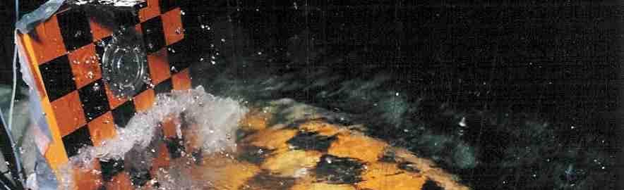
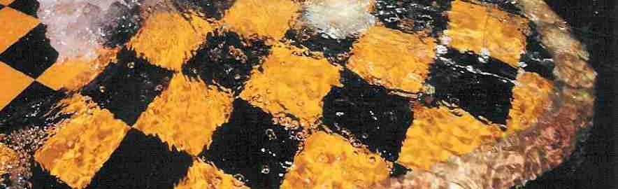
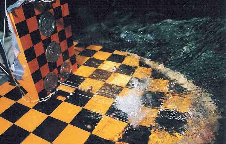
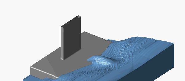
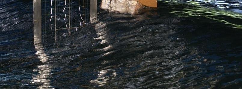
5 - The fluid simulations are carried out on a Cartesian grid with user-defined stretching. The Cartesian grid is fixed in the domain. When the domain is moving a virtual body force is added to the forcing term in the Navier-Stokes equations. The fluid motions are thus solved in a domain-fixed co-ordinate system. - To distinguish between the different characters of grid cells, the cells are labelled. The Navier-Stokes equations are discretised and solved in cells that contain fluid. The free-surface displacement is described by the Volume Of Fluid method with a local height function. - The generation of waves, which has been accomplished by specifying fluid velocities at the inflow boundary of the fluid domain. The fluid velocities are obtained from potential flow. Linear waves (Airy waves) and fifth-order waves (Stokes waves) have been implemented. The linear waves have been stretched towards the actual position of the free surface using Wheeler stretching. - Several absorbing boundary conditions at the outflow boundaries. - The possibility to use the velocity field from a (de-coupled) linear diffraction theory. Linear diffraction theory is used to compute body motions and fluid velocities which are then used in ComFLOW to prescribe the body motions and fluid velocities on the inflow and outflow boundaries. - An off-line coupling with a structural-analysis code has been established to compute the response of a structure to high peak loads. Simulation and model test results The ivof method has now been applied to the problem of a subsea structure in the splash zone. Specific model tests were carried out to validate the simulations. Figure 8 shows the model of the subsea structure in the model basin. It was build at scale 1:40 and its main dimensions are given in Figure 9 and Table 1. Two series of tests were carried out: A. Tests with the subsea structure captive in a force and moment frame to determine the wave exciting loads in 6 degrees of freedom. B. Tests with the subsea structure free-hanging in slings. For the present paper only the results for Series A with the captive model are used. Series B will be used in a later phase to check the fully coupled motion of the subsea structure in waves. Figure 10 shows the captive force measurement set-up in the basin and Figure 11 presents the two extreme positions tested: the subsea structure just above the free surface and just fully submerged. In addition to these positions, also an intermediate draft was tested. Figure 12 shows several examples of the complex flow in and around the subsea structure in waves observed during the tests. This flow is characterised by aspects such as: Added mass and damping effects of the water under, above and in the subsea structure Buoyancy effects in the waves Impact loads against horizontal plates in the subsea structure Flow through openings in the top and bottom of the subsea structure Complex flow through the equipment of the subsea structure Water captured temporarely in certain parts of the subsea structure In the free-hanging situation during the lift, this can result in unwanted oscillations, slack lines and larger vertical loads in the slings than expected. The numerical model of the subsea structure above the approaching wave is shown in Figure 13. This model was built with basic shapes such as beams, boxes and cylinders. The dominant components in the subsea structure were all modelled. The computational domain contained a total number of 170 * 100 * 100 (= ) cells. Figure 14 shows a number of snapshots of the flow around the subsea structure in different phases during a simulation in waves. The flow around and through the structure looks very realistic and shows a strong resemblance with the observation from the model tests. A quantitative comparison of the vertical load on the subsea structure is given in Figure 15. The simulated load is given in blue and measured load is given in red. In the simulations only one wave oscillation was calculated. This was done because the calculation is extremely time consuming: 65 hours on a 2.4 MHz PC for a simulation of 1 wave period! The comparison between the simulation and model test is reasonably good. The total load levels are reasonably predicted. However, the simulation shows load peaks that are not present in the model tests and lachs some of the oscillations that are observed in the tests. These differences need further investigation.
6 Conclusions The improved Volume Of Fluid (ivof) method presented in the present paper is a potential candidate for the better numerical prediction of the behaviour of a subsea structure in the splash zone. Based on the initial comparison between dedicated model tests and simulations the following conclusions seem justified: - The simulated flow around and through the structure looks very realistic and shows a strong resemblance with observations from model tests. - The quantitative comparison of the vertical load on the subsea structure shows that the total load levels are well predicted. - However, the simulation shows load peaks that are not present in the model tests and misses some of the oscillations that are observed in the tests. These differences need further investigation. This good initial comparison shows the potential of the improved Volumes Of Fluid (ivof) method for the simulation of the behaviour of subsea structures in the splash zone. However, significant further development and validation is needed before a fully coupled simulation of the subsea structure and its lifting vessel in waves can be carried out. This possibility is also affected by the long simulation times required at the moment. As an intermediate step the method might be used to determine the wave loads and added mass in an uncoupled simulation. References 1. Buchner, B.; Green Water on Ship-type Offshore Structures, PhD thesis Delft University of Technology, Gerrits, J., Loots, G.E., Fekken, G. and Veldman, A.E.P.; Liquid Sloshing on Earth and in Space, In: Moving Boundaries V (Sarler, B., Brebbia, C.A. and Power, H. Eds.) WIT Press, Southampton, pp , Gerrits, J.; Dynamics of Liquid-Filled Spacecraft, Numerical Simulation of Coupled Solid-Liquid Dynamics, PhD thesis, RuG, Fekken, G., Veldman, A.E.P. and Buchner, B.; Simulation of Green Water Flow Using the Navier-Stokes Equations, Seventh International Conference on Numerical Ship Hydromechanics, Nantes, Daalen, E.F.G. van, Kleefsman, K.M.T., Gerrits, J., Luth, H.R. and Veldman, A.E.P.; Anti Roll Tank Simulations with a Volume Of Fluid (VOF) based Navier-Stokes Solver, 23rd Symposium on Naval Hydrodynamics, Val de Reuil, September Buchner, B., Bunnik, T.H.J., Fekken, G. and Veldman, A.E.P.; A Numerical Study on Wave Run Up on an FPSO Bow, OMAE2001, Rio de Janeiro, Hirt, C.W. and Nichols, B.D.; Volume Of Fluid (VOF) Method for the Dynamics of Free Boundaries, Journal of Computational Physics, 39, pp , Kleefsman, K.M.T., Fekken, G., Veldman, A.E.P., Bunnik, T., Buchner, B. and Iwanowski, B.; Prediction of green water and wave impact loading using a Navier-Stokes Based Simulation Tool, OMAE conference, Oslo, 2002.
7 Table 1: Main dimensions and weight distribution of the subsea structure (1:40 scale) M 266 t KG 4.96 m K xx 2.68 m K yy 4.96 m K zz 4.80 m


8 Figure 1: Examples of different complex subsea structures in the splash zone


9 Figure 2: Example of earlier application of the method: green water on the deck of an FPSO Figure 3: Example of earlier application of the method: wave in deck loading on a fixed platform
10 y F -F = 0.5 b s A = x 0.2 F = 0.3 s A = 0.5 y x Figure 4: Two-dimensional example of a grid cell using apertures Figure 5: Geometry cell labelling (left) and free-surface cell labelling (right) for a wedge entering a fluid p v p u p u p v p Figure 6: Location of the pressure and velocity components in the staggered grid

11 N NW NE h y W w C e E SW SE S h x Figure 7: Spatial discretisation cell, using compass indication for cell phases Figure 8: Model of a subsea structure in the model basin Figure 9: Main dimensions of the subsea structure model (dimensions in m full-scale, scale model 1:40)

12 Figure 10: Subsea structure in captive force measurement set-up Figure 11: Subsea structure in captive force measurement set-up at the two extreme positions tested: just above the free surface and just fully submerged


13 Figure 12: several examples of complex flow in and around the subsea structure in waves

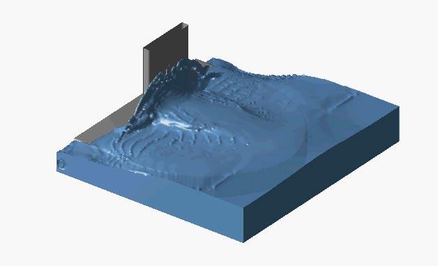
14 Figure 13: Numerical model of subsea structure

15 Figure 14: The subsea structure in different phases during the simulation in waves
16 Fz [kn] time [s] Figure 15: Simulated (blue) and measured vertical force on the subsea structure
Simulation of Offshore Wave Impacts with a Volume of Fluid Method. Tim Bunnik Tim Bunnik MARIN
 Simulation of Offshore Wave Impacts with a Volume of Fluid Method Tim Bunnik Tim Bunnik MARIN Outline Part I: Numerical method -Overview Part II: Applications - Dambreak - Wave run-up - Sloshing loads
THE NUMERICAL SIMULATION OF GREEN WATER LOADING INCLUDING VESSEL MOTIONS AND THE INCOMING WAVE FIELD
 Proceedings of OMAE 05 24th International Conference on Offshore Mechanics and Arctic Engineering (OMAE 2005) June, 12-17, 2005, Halkidiki, Greece OMAE2005-67448 THE NUMERICAL SIMULATION OF GREEN WATER
Water Impact Loading on Offshore Structures
 Water Impact Loading on Offshore Structures A Numerical Study Theresa Kleefsman The research presented in this thesis was funded by the European Community under the Competitive and Sustainable Growth Programme
Simulation of Sloshing Dynamics in a Tank by an Improved Volume-of-Fluid Method
 Proceedings of the Nineteenth (2009) International Offshore and Polar Engineering Conference Osaka, Japan, June 21-26, 2009 Copyright 2009 by The International Society of Offshore and Polar Engineers (ISOPE)
Citation for published version (APA): Kleefsman, K. M. T. (2005). Water impact loading on offshore structures. - A numerical study s.n.
: Kleefsman, K. M. T. (2005). Water impact loading on offshore structures. - A numerical study s.n.") University of Groningen Water impact loading on offshore structures. - A numerical study Kleefsman, Kornelia Marchien Theresa IMPORTANT NOTE: You are advised to consult the publisher's version (publisher's
University of Groningen Water impact loading on offshore structures. - A numerical study Kleefsman, Kornelia Marchien Theresa IMPORTANT NOTE: You are advised to consult the publisher's version (publisher's
Realistic Animation of Fluids
 1 Realistic Animation of Fluids Nick Foster and Dimitris Metaxas Presented by Alex Liberman April 19, 2005 2 Previous Work Used non physics-based methods (mostly in 2D) Hard to simulate effects that rely
AN IMPROVED VOLUME-OF-FLUID (IVOF) METHOD FOR WAVE IMPACT TYPE PROBLEMS. K.M.Theresa Kleefsman, Arthur E.P. Veldman
 METHOD FOR WAVE IMPACT TYPE PROBLEMS. K.M.Theresa Kleefsman, Arthur E.P. Veldman") Proceedings of OMAE-FPSO 2004 OMAE Speciality Symposium on FPSO Integrity 2004, Houston, USA OMAE-FPSO 04-0066 AN IMPROVED VOLUME-OF-FLUID (IVOF) METHOD FOR WAVE IMPACT TYPE PROBLEMS K.M.Teresa Kleefsman,
Proceedings of OMAE-FPSO 2004 OMAE Speciality Symposium on FPSO Integrity 2004, Houston, USA OMAE-FPSO 04-0066 AN IMPROVED VOLUME-OF-FLUID (IVOF) METHOD FOR WAVE IMPACT TYPE PROBLEMS K.M.Teresa Kleefsman,
Numerical Estimation and Validation of Shallow Draft Effect on Roll Damping
 The 14 th International Ship Stability Workshop (ISSW), 29 th September- 1 st October 2014, Kuala Lumpur, Malaysia Numerical Estimation and Validation of Shallow Draft Effect on Roll Damping Toru Katayama
COMPARISON OF FULL-SCALE MEASUREMENTS WITH CALCULATED MOTION CHARACTERISTICS OF A WEST OF AFRICA FPSO
 Proceedings of OMAE3 ND International Conference on Offshore Mechanics and Arctic Engineering June 8 3, 3, Cancun, Mexico OMAE3-378 COMPARISON OF FULL-SCALE MEASUREMENTS WITH CALCULATED MOTION CHARACTERISTICS
A Volume-of-Fluid based simulation method for wave impact problems Kleefsman, K.M.T.; Fekken, G.; Veldman, Arthur; Iwanowski, B.; Buchner, B.
 University of Groningen A Volume-of-Fluid based simulation method for wave impact problems Kleefsman, K.M.T.; Fekken, G.; Veldman, Arthur; Iwanowski, B.; Buchner, B. Published in: Journal of computational
Development of the Compliant Mooring Line Model for FLOW-3D
 Flow Science Report 08-15 Development of the Compliant Mooring Line Model for FLOW-3D Gengsheng Wei Flow Science, Inc. October 2015 1. Introduction Mooring systems are common in offshore structures, ship
ANTI-ROLL TANK SIMULATIONS WITH A VOLUME OF FLUID (VOF) BASED NAVIER-STOKES SOLVER
 BASED NAVIER-STOKES SOLVER") ANTI-ROLL TANK SIMULATIONS WITH A VOLUME OF FLUID (VOF) BASED NAVIER-STOKES SOLVER E.F.G. van Daalen 1, K.M.T. Kleefsman 2, J. Gerrits 2, H.R. Luth 1, A.E.P. Veldman 2 ( 1 MARIN, P.O. Box 28, 67 AA Wageningen,
ANTI-ROLL TANK SIMULATIONS WITH A VOLUME OF FLUID (VOF) BASED NAVIER-STOKES SOLVER E.F.G. van Daalen 1, K.M.T. Kleefsman 2, J. Gerrits 2, H.R. Luth 1, A.E.P. Veldman 2 ( 1 MARIN, P.O. Box 28, 67 AA Wageningen,
Experimental Validation of the Computation Method for Strongly Nonlinear Wave-Body Interactions
 Experimental Validation of the Computation Method for Strongly Nonlinear Wave-Body Interactions by Changhong HU and Masashi KASHIWAGI Research Institute for Applied Mechanics, Kyushu University Kasuga
CFD FOR OFFSHORE APPLICATIONS USING REFRESCO. Arjen Koop - Senior Project Manager Offshore MARIN
 CFD FOR OFFSHORE APPLICATIONS USING REFRESCO Arjen Koop - Senior Project Manager Offshore MARIN COMPUTATIONAL FLUID DYNAMICS (CFD) Advantages: Quantitative predictions Detailed insight in physical processes
Simulation of a Free Surface Flow over a Container Vessel Using CFD
 Simulation of a Free Surface Flow over a Container Vessel Using CFD Krishna Atreyapurapu 1 Bhanuprakash Tallapragada 2 Kiran Voonna 3 M.E Student Professor Manager Dept. of Marine Engineering Dept. of
Aurélien Thinat Stéphane Cordier 1, François Cany
 SimHydro 2012:New trends in simulation - Hydroinformatics and 3D modeling, 12-14 September 2012, Nice Aurélien Thinat, Stéphane Cordier, François Cany Application of OpenFOAM to the study of wave loads
Fluid-structure Interaction by the mixed SPH-FE Method with Application to Aircraft Ditching
 Fluid-structure Interaction by the mixed SPH-FE Method with Application to Aircraft Ditching Paul Groenenboom ESI Group Delft, Netherlands Martin Siemann German Aerospace Center (DLR) Stuttgart, Germany
Realistic Animation of Fluids
 Realistic Animation of Fluids p. 1/2 Realistic Animation of Fluids Nick Foster and Dimitri Metaxas Realistic Animation of Fluids p. 2/2 Overview Problem Statement Previous Work Navier-Stokes Equations
MESHLESS SOLUTION OF INCOMPRESSIBLE FLOW OVER BACKWARD-FACING STEP
 Vol. 12, Issue 1/2016, 63-68 DOI: 10.1515/cee-2016-0009 MESHLESS SOLUTION OF INCOMPRESSIBLE FLOW OVER BACKWARD-FACING STEP Juraj MUŽÍK 1,* 1 Department of Geotechnics, Faculty of Civil Engineering, University
SOFTWARE. Sesam user course. 20 February 2017 Wadam - General wave load analysis. Ungraded SAFER, SMARTER, GREENER DNV GL 2014
 SOFTWARE Sesam user course DNV GL 1 SAFER, SMARTER, GREENER Wave Analysis by Diffraction And Morison theory Computation of wave loads and global response 2 Diffraction & radiation theory Structural part
CGT 581 G Fluids. Overview. Some terms. Some terms
 CGT 581 G Fluids Bedřich Beneš, Ph.D. Purdue University Department of Computer Graphics Technology Overview Some terms Incompressible Navier-Stokes Boundary conditions Lagrange vs. Euler Eulerian approaches
The Study of Ship Motions in Regular Waves using a Mesh-Free Numerical Method
 The Study of Ship Motions in Regular Waves using a Mesh-Free Numerical Method by Bruce Kenneth Cartwright, B. Eng., M. Sc. Submitted in fulfilment of the requirements for the Degree of Master of Philosophy
An Improved Volume-of-Fluid Method for Wave Impact Problems
 An Improved Volume-of-Fluid Metod for Wave Impact Problems K.M. Teresa Kleefsman, Geert Fekken, Artur E.P. Veldman Dept. of Matematics and Computing Science, University of Groningen Groningen, te Neterlands
Investigation of cross flow over a circular cylinder at low Re using the Immersed Boundary Method (IBM)
") Computational Methods and Experimental Measurements XVII 235 Investigation of cross flow over a circular cylinder at low Re using the Immersed Boundary Method (IBM) K. Rehman Department of Mechanical Engineering,
Computational Methods and Experimental Measurements XVII 235 Investigation of cross flow over a circular cylinder at low Re using the Immersed Boundary Method (IBM) K. Rehman Department of Mechanical Engineering,
CFD Analysis of a Novel Hull Design for an Offshore Wind Farm Service Vessel
 CFD Analysis of a Novel Hull Design for an Offshore Wind Farm Service Vessel M. Shanley 1, J. Murphy 1, and P. Molloy 2 1 Hydraulics and Maritime, Civil and Environmental Engineering University College
2D numerical simulation of ocean waves
 2D numerical simulation of ocean waves Qingjie. Du,*, Y.C. Dennis. Leung Department of Mechanical Engineering, The University of Hong Kong, Hong Kong, China * Corresponding author. Tel: +852 51743593,
NUMERICAL SIMULATIONS OF TWO-PHASE FLOW WITH COMFLOW: PAST AND RECENT DEVELOPMENTS
 European Congress on Computational Methods in Applied Sciences and Engineering (ECCOMAS 2012) J. Eberhardsteiner et.al. (eds.) Vienna, Austria, September 10-14, 2012 NUMERICAL SIMULATIONS OF TWO-PHASE
EXPERIMENTAL VALIDATION OF STAR-CCM+ FOR LIQUID CONTAINER SLOSH DYNAMICS
 EXPERIMENTAL VALIDATION OF STAR-CCM+ FOR LIQUID CONTAINER SLOSH DYNAMICS Brandon Marsell a.i. solutions, Launch Services Program, Kennedy Space Center, FL 1 Agenda Introduction Problem Background Experiment
WAVE PATTERNS, WAVE INDUCED FORCES AND MOMENTS FOR A GRAVITY BASED STRUCTURE PREDICTED USING CFD
 Proceedings of the ASME 2011 30th International Conference on Ocean, Offshore and Arctic Engineering OMAE2011 June 19-24, 2011, Rotterdam, The Netherlands OMAE2011-49593 WAVE PATTERNS, WAVE INDUCED FORCES
Parallelization study of a VOF/Navier-Stokes model for 3D unstructured staggered meshes
 Parallelization study of a VOF/Navier-Stokes model for 3D unstructured staggered meshes L. Jofre, O. Lehmkuhl, R. Borrell, J. Castro and A. Oliva Corresponding author: cttc@cttc.upc.edu Centre Tecnològic
NUMERICAL MODELING STUDY FOR FLOW PATTERN CHANGES INDUCED BY SINGLE GROYNE
 NUMERICAL MODELING STUDY FOR FLOW PATTERN CHANGES INDUCED BY SINGLE GROYNE Jungseok Ho 1, Hong Koo Yeo 2, Julie Coonrod 3, and Won-Sik Ahn 4 1 Research Assistant Professor, Dept. of Civil Engineering,
1.2 Numerical Solutions of Flow Problems
 1.2 Numerical Solutions of Flow Problems DIFFERENTIAL EQUATIONS OF MOTION FOR A SIMPLIFIED FLOW PROBLEM Continuity equation for incompressible flow: 0 Momentum (Navier-Stokes) equations for a Newtonian
Continued Investigation of Small-Scale Air-Sea Coupled Dynamics Using CBLAST Data
 Continued Investigation of Small-Scale Air-Sea Coupled Dynamics Using CBLAST Data Dick K.P. Yue Center for Ocean Engineering Department of Mechanical Engineering Massachusetts Institute of Technology Cambridge,
2.7 Cloth Animation. Jacobs University Visualization and Computer Graphics Lab : Advanced Graphics - Chapter 2 123
 2.7 Cloth Animation 320491: Advanced Graphics - Chapter 2 123 Example: Cloth draping Image Michael Kass 320491: Advanced Graphics - Chapter 2 124 Cloth using mass-spring model Network of masses and springs
SPH: Towards the simulation of wave-body interactions in extreme seas
 SPH: Towards the simulation of wave-body interactions in extreme seas Guillaume Oger, Mathieu Doring, Bertrand Alessandrini, and Pierre Ferrant Fluid Mechanics Laboratory (CNRS UMR6598) Ecole Centrale
Three-dimensional simulation of floating wave power device Xixi Pan 1, a, Shiming Wang 1, b, Yongcheng Liang 1, c
 International Power, Electronics and Materials Engineering Conference (IPEMEC 2015) Three-dimensional simulation of floating wave power device Xixi Pan 1, a, Shiming Wang 1, b, Yongcheng Liang 1, c 1 Department
Water. Notes. Free surface. Boundary conditions. This week: extend our 3D flow solver to full 3D water We need to add two things:
 Notes Added a 2D cross-section viewer for assignment 6 Not great, but an alternative if the full 3d viewer isn t working for you Warning about the formulas in Fedkiw, Stam, and Jensen - maybe not right
LS-DYNA 980 : Recent Developments, Application Areas and Validation Process of the Incompressible fluid solver (ICFD) in LS-DYNA.
 in LS-DYNA.") 12 th International LS-DYNA Users Conference FSI/ALE(1) LS-DYNA 980 : Recent Developments, Application Areas and Validation Process of the Incompressible fluid solver (ICFD) in LS-DYNA Part 1 Facundo Del
12 th International LS-DYNA Users Conference FSI/ALE(1) LS-DYNA 980 : Recent Developments, Application Areas and Validation Process of the Incompressible fluid solver (ICFD) in LS-DYNA Part 1 Facundo Del
A 3D VOF model in cylindrical coordinates
 A 3D VOF model in cylindrical coordinates Marmar Mehrabadi and Markus Bussmann Department of Mechanical and Industrial Engineering, University of Toronto Recently, volume of fluid (VOF) methods have improved
Computational Fluid Dynamics using OpenCL a Practical Introduction
 19th International Congress on Modelling and Simulation, Perth, Australia, 12 16 December 2011 http://mssanz.org.au/modsim2011 Computational Fluid Dynamics using OpenCL a Practical Introduction T Bednarz
The Flow Around FPSO s in Steep Regular Waves.
 The Flow Around FPSO s in Steep Regular Waves. R.H.M.Huijsmans, J. P. Borleteau Maritime Research Institute Netherlands, Wageningen, Netherlands, Email: r.h.m.huijsmans@marin.nl SIREHNA, Nantes, France.
Animation of Fluids. Animating Fluid is Hard
 Animation of Fluids Animating Fluid is Hard Too complex to animate by hand Surface is changing very quickly Lots of small details In short, a nightmare! Need automatic simulations AdHoc Methods Some simple
Transactions on Modelling and Simulation vol 10, 1995 WIT Press, ISSN X
 Hydrodynamic coefficients and motions due to a floating cylinder in waves D.D. Bhatta, M. Rahman Department of Applied Mathematics, Technical University of Nova Scotia, Halifax, Nova Scotia, Canada B3J
ComFLOW RuG. Roel Luppes
 ComFLOW Developments @ RuG Roel Luppes Actions Roel Luppes 1. Last ComFLOW version (v2.3): December 08 Since then: 50% of time available for ComFLOW matters 2. Helpdesk contacts since December 08 Akersolutions
Available online at ScienceDirect. Procedia Engineering 136 (2016 ) Dynamic analysis of fuel tank
 Dynamic analysis of fuel tank") Available online at www.sciencedirect.com ScienceDirect Procedia Engineering 136 (2016 ) 45 49 The 20 th International Conference: Machine Modeling and Simulations, MMS 2015 Dynamic analysis of fuel tank
Available online at www.sciencedirect.com ScienceDirect Procedia Engineering 136 (2016 ) 45 49 The 20 th International Conference: Machine Modeling and Simulations, MMS 2015 Dynamic analysis of fuel tank
Solving Partial Differential Equations on Overlapping Grids
 **FULL TITLE** ASP Conference Series, Vol. **VOLUME**, **YEAR OF PUBLICATION** **NAMES OF EDITORS** Solving Partial Differential Equations on Overlapping Grids William D. Henshaw Centre for Applied Scientific
 A Contact Angle Model for the Parallel Free Surface Lattice Boltzmann Method in walberla Stefan Donath (stefan.donath@informatik.uni-erlangen.de) Computer Science 10 (System Simulation) University of Erlangen-Nuremberg
DEVELOPMENT OF NUMERICAL TOOL FOR HYDRODYNAMICS SIMULATION OF HIGH SPEED PLANING CRAFTS
 DEVELOPMENT OF NUMERICAL TOOL FOR HYDRODYNAMICS SIMULATION OF HIGH SPEED PLANING CRAFTS Ebrahim Jahanbakhsh Marine Lab., Sharif Uni. of Tech., Tehran/Iran, ebrahim_jahan@yahoo.com Roozbeh Panahi Tarbiat
Offshore Platform Fluid Structure Interaction (FSI) Simulation
 Simulation") Offshore Platform Fluid Structure Interaction (FSI) Simulation Ali Marzaban, CD-adapco Murthy Lakshmiraju, CD-adapco Nigel Richardson, CD-adapco Mike Henneke, CD-adapco Guangyu Wu, Chevron Pedro M. Vargas,
Offshore Platform Fluid Structure Interaction (FSI) Simulation Ali Marzaban, CD-adapco Murthy Lakshmiraju, CD-adapco Nigel Richardson, CD-adapco Mike Henneke, CD-adapco Guangyu Wu, Chevron Pedro M. Vargas,
Numerical and experimental investigations into liquid sloshing in a rectangular tank
 The 2012 World Congress on Advances in Civil, Environmental, and Materials Research (ACEM 12) Seoul, Korea, August 26-30, 2012 Numerical and experimental investigations into liquid sloshing in a rectangular
Coupling of STAR-CCM+ to Other Theoretical or Numerical Solutions. Milovan Perić
 Coupling of STAR-CCM+ to Other Theoretical or Numerical Solutions Milovan Perić Contents The need to couple STAR-CCM+ with other theoretical or numerical solutions Coupling approaches: surface and volume
Interaction of Fluid Simulation Based on PhysX Physics Engine. Huibai Wang, Jianfei Wan, Fengquan Zhang
 4th International Conference on Sensors, Measurement and Intelligent Materials (ICSMIM 2015) Interaction of Fluid Simulation Based on PhysX Physics Engine Huibai Wang, Jianfei Wan, Fengquan Zhang College
Numerical Modeling Study for Fish Screen at River Intake Channel ; PH (505) ; FAX (505) ;
 ; FAX (505) ;") Numerical Modeling Study for Fish Screen at River Intake Channel Jungseok Ho 1, Leslie Hanna 2, Brent Mefford 3, and Julie Coonrod 4 1 Department of Civil Engineering, University of New Mexico, Albuquerque,
Numerical Modeling Study for Fish Screen at River Intake Channel Jungseok Ho 1, Leslie Hanna 2, Brent Mefford 3, and Julie Coonrod 4 1 Department of Civil Engineering, University of New Mexico, Albuquerque,
Numerical Simulation of Coupled Fluid-Solid Systems by Fictitious Boundary and Grid Deformation Methods
 Numerical Simulation of Coupled Fluid-Solid Systems by Fictitious Boundary and Grid Deformation Methods Decheng Wan 1 and Stefan Turek 2 Institute of Applied Mathematics LS III, University of Dortmund,
A MULTIPHASE CFD METHOD FOR PREDICTION OF FLOODWATER DYNAMICS
 10 th International Conference 307 A MULTIPHASE CFD METHOD FOR PREDICTION OF FLOODWATER DYNAMICS Zhiliang Gao 1, Dracos Vassalos 1, Qiuxin Gao 1 1 Department of Naval Architecture and Marine Engineering,
Navier-Stokes & Flow Simulation
 Last Time? Navier-Stokes & Flow Simulation Implicit Surfaces Marching Cubes/Tetras Collision Detection & Response Conservative Bounding Regions backtracking fixing Today Flow Simulations in Graphics Flow
Drop Impact Simulation with a Velocity-Dependent Contact Angle
 ILASS Americas 19th Annual Conference on Liquid Atomization and Spray Systems, Toronto, Canada, May 2006 Drop Impact Simulation with a Velocity-Dependent Contact Angle S. Afkhami and M. Bussmann Department
Use of STAR-CCM+ in Marine and Off-Shore Engineering - Key Features and Future Developments - M. Perić, F. Schäfer, E. Schreck & J.
 Use of STAR-CCM+ in Marine and Off-Shore Engineering - Key Features and Future Developments - M. Perić, F. Schäfer, E. Schreck & J. Singh Contents Main features of STAR-CCM+ relevant for marine and offshore
A Direct Simulation-Based Study of Radiance in a Dynamic Ocean
 1 DISTRIBUTION STATEMENT A. Approved for public release; distribution is unlimited. A Direct Simulation-Based Study of Radiance in a Dynamic Ocean LONG-TERM GOALS Dick K.P. Yue Center for Ocean Engineering
Parametric Study of Sloshing Effects in the Primary System of an Isolated LFR Marti Jeltsov, Walter Villanueva, Pavel Kudinov
 1 Parametric Study of Sloshing Effects in the Primary System of an Isolated LFR 19.06.2013 Marti Jeltsov, Walter Villanueva, Pavel Kudinov Division of Nuclear Power Safety Royal Institute of Technology
THE SIMULATION OF VIOLENT FREE-SURFACE DYNAMICS AT SEA AND IN SPACE
 European Conference on Computational Fluid Dynamics ECCOMAS CFD 2006 P. Wesseling, E. Oñate and J. Périaux (Eds) c TU Delft, The Netherlands, 2006 THE SIMULATION OF VIOLENT FREE-SURFACE DYNAMICS AT SEA
Eng Ship Structures 1 L E C T U R E 1 0 : F I N I T E E L E M E N T T E C H N I Q U E S I N S H I P S T R U C T U R A L D E S I G N
 Eng. 6002 Ship Structures 1 L E C T U R E 1 0 : F I N I T E E L E M E N T T E C H N I Q U E S I N S H I P S T R U C T U R A L D E S I G N Contents Introduction Linear Analysis Static Non-linear Analysis
Report No CPO FUNCTIONAL SPECIFICATIONS GRAPHICAL USER INTERFACE SHUTTLE. Version 2.0
 MARIN 2, Haagsteeg P.O. Box 28 6700 AA Wageningen The Netherlands Phone +31 317 493911 Fax +31 317 493245 Internet www.marin.nl E-mail info@marin.nl Report No. 16656-2-CPO FUNCTIONAL SPECIFICATIONS GRAPHICAL
Sloshing reduction effect of splitting wall in cylindrical tank
 Sloshing reduction effect of splitting wall in cylindrical tank D.Takabatake 1, S.Sawada 2, N.Yoneyama 2 and M.Miura 3 1 Central Research Institute of Electric Power Industry, 1646,Abiko, Abiko, Chiba,
ALE Seamless Immersed Boundary Method with Overset Grid System for Multiple Moving Objects
 Tenth International Conference on Computational Fluid Dynamics (ICCFD10), Barcelona,Spain, July 9-13, 2018 ICCFD10-047 ALE Seamless Immersed Boundary Method with Overset Grid System for Multiple Moving
OMAE SLOSHING AND SWIRLING IN PARTIALLY LOADED PRISMATIC CHAMFERED TANKS
 Proceedings of the 36 th International Conference on Ocean, Offshore & Arctic Engineering June 25-30, 2017, Trondheim, Norway OMAE2017-61562 SLOSHING AND SWIRLING IN PARTIALLY LOADED PRISMATIC CHAMFERED
CFD modelling of thickened tailings Final project report
 26.11.2018 RESEM Remote sensing supporting surveillance and operation of mines CFD modelling of thickened tailings Final project report Lic.Sc.(Tech.) Reeta Tolonen and Docent Esa Muurinen University of
NUMERICAL STUDY OF TWO DIFFERENT TYPES OF SEMI-SUBMERSIBLE PLATFORMS WITH MOORING SYSTEMS IN THE SEA
 NUMERICAL STUDY OF TWO DIFFERENT TYPES OF SEMI-SUBMERSIBLE PLATFORMS WITH MOORING SYSTEMS IN THE SEA Yao Peng, Decheng Wan* State Key Laboratory of Ocean Engineering, School of Naval Architecture, Ocean
A dynamic model for lifting heavy modules between two floating offshore structures
 A dynamic model for lifting heavy modules between two floating offshore structures Radboud R.T. van Dijk Maritime Research Institute Netherlands (MARIN), Netherlands Alex A. Hendriks Heerema Marine Contractors
Navier-Stokes & Flow Simulation
 Last Time? Navier-Stokes & Flow Simulation Optional Reading for Last Time: Spring-Mass Systems Numerical Integration (Euler, Midpoint, Runge-Kutta) Modeling string, hair, & cloth HW2: Cloth & Fluid Simulation
Navier-Stokes & Flow Simulation
 Last Time? Navier-Stokes & Flow Simulation Pop Worksheet! Teams of 2. Hand in to Jeramey after we discuss. Sketch the first few frames of a 2D explicit Euler mass-spring simulation for a 2x3 cloth network
Characteristic Aspects of SPH Solutions
 Characteristic Aspects of SPH Solutions for Free Surface Problems: Source and Possible Treatment of High Frequency Numerical Oscillations of Local Loads. A. Colagrossi*, D. Le Touzé & G.Colicchio* *INSEAN
Adarsh Krishnamurthy (cs184-bb) Bela Stepanova (cs184-bs)
 Bela Stepanova (cs184-bs)") OBJECTIVE FLUID SIMULATIONS Adarsh Krishnamurthy (cs184-bb) Bela Stepanova (cs184-bs) The basic objective of the project is the implementation of the paper Stable Fluids (Jos Stam, SIGGRAPH 99). The final
OBJECTIVE FLUID SIMULATIONS Adarsh Krishnamurthy (cs184-bb) Bela Stepanova (cs184-bs) The basic objective of the project is the implementation of the paper Stable Fluids (Jos Stam, SIGGRAPH 99). The final
2-D Tank Sloshing Using the Coupled Eulerian- LaGrangian (CEL) Capability of Abaqus/Explicit
 Capability of Abaqus/Explicit") 2-D Tank Sloshing Using the Coupled Eulerian- LaGrangian (CEL) Capability of Abaqus/Explicit Jeff D. Tippmann, Sharat C. Prasad 2, and Parthiv N. Shah ATA Engineering, Inc. San Diego, CA 923 2 Dassault
2-D Tank Sloshing Using the Coupled Eulerian- LaGrangian (CEL) Capability of Abaqus/Explicit Jeff D. Tippmann, Sharat C. Prasad 2, and Parthiv N. Shah ATA Engineering, Inc. San Diego, CA 923 2 Dassault
Modeling Khowr-e Musa Multi-Branch Estuary Currents due to the Persian Gulf Tides Using NASIR Depth Average Flow Solver
 Journal of the Persian Gulf (Marine Science)/Vol.1/No.1/September 2010/6/45-50 Modeling Khowr-e Musa Multi-Branch Estuary Currents due to the Persian Gulf Tides Using NASIR Depth Average Flow Solver Sabbagh-Yazdi,
Marine Hydrodynamics Solver in OpenFOAM
 Marine Hydrodynamics Solver in OpenFOAM p. 1/14 Marine Hydrodynamics Solver in OpenFOAM Hrvoje Jasak and Henrik Rusche h.jasak@wikki.co.uk, h.rusche@wikki.co.uk Wikki, United Kingdom and Germany 4 December
ESTIMATION OF CROSS-FLOW INFLUENCE ON SPRING-MOUNTED CYLINDER IN TRIANGULAR CYLINDER ARRAY.
 ESTIMATION OF CROSS-FLOW INFLUENCE ON SPRING-MOUNTED CYLINDER IN TRIANGULAR CYLINDER ARRAY Sabine Upnere 1,2, Normunds Jekabsons 2,3 1 Riga Technical University, Latvia; 2 Ventspils University College,
Simulation Technology for Offshore and Marine Hydrodynamics Status Review and Emerging Capabilities
 Simulation Technology for Offshore and Marine Hydrodynamics Status Review and Emerging Capabilities Lee Sing-Kwan and Seah Ah Kuan American Bureau of Shipping Presented at the 2 nd International MTEC 2007
A Direct Simulation-Based Study of Radiance in a Dynamic Ocean
 A Direct Simulation-Based Study of Radiance in a Dynamic Ocean Lian Shen Department of Civil Engineering Johns Hopkins University Baltimore, MD 21218 phone: (410) 516-5033 fax: (410) 516-7473 email: LianShen@jhu.edu
ITTC Recommended Procedures and Guidelines
 Page 1 of 13 Table of Contents Codes in the Frequency Domain... 2 1. PURPOSE OF PROCEDURE... 2 2. SCOPE... 2 2.1 Present Theoretical Limitations... 4 2.2 Numerical Aspects... 4 2.3 Software Engineering
Generation and propagation of solitary wave over a steep sloping beach
 Generation and propagation of solitary wave over a steep sloping beach Zouhaier Hafsia (1), Mehdi Ben Haj (2), Hedi Lamloumi (3), Khlifa Maalel (4) and Ridha Zgolli (5) (1-5) ENIT. Laboratoire d Hydraulique
Numerical Methods in Aerodynamics. Fluid Structure Interaction. Lecture 4: Fluid Structure Interaction
 Fluid Structure Interaction Niels N. Sørensen Professor MSO, Ph.D. Department of Civil Engineering, Alborg University & Wind Energy Department, Risø National Laboratory Technical University of Denmark
Nonlinear Potential Flow Solver Development in OpenFOAM
 Nonlinear Potential Flow Solver Development in OpenFOAM A. Mehmood Plymouth University, UK April 19,2016 A. Mehmood Table of Contents 1 Motivation 2 Solution Methodology Mathematical Formulation Sequence
COMPUTATIONAL INVESTIGATION OF FREE SURFACE FLOW AROUND A SHIP HULL
 COMPUTATIONAL INVESTIGATION OF FREE SURFACE FLOW AROUND A SHIP HULL Katuri Samarpana, Ajay konapala, Duvvada Ramesh M.V.G.R.College of Engineering / Mechanical, Vizianagaram, India ABSTRACT Ship hydrodynamics
Analysis of Fluid-Structure Interaction Effects of Liquid-Filled Container under Drop Testing
 Kasetsart J. (Nat. Sci.) 42 : 165-176 (2008) Analysis of Fluid-Structure Interaction Effects of Liquid-Filled Container under Drop Testing Chakrit Suvanjumrat*, Tumrong Puttapitukporn and Satjarthip Thusneyapan
A Direct Simulation-Based Study of Radiance in a Dynamic Ocean
 A Direct Simulation-Based Study of Radiance in a Dynamic Ocean Dick K.P. Yue Center for Ocean Engineering Massachusetts Institute of Technology Room 5-321, 77 Massachusetts Ave, Cambridge, MA 02139 phone:
SIMULATION OF INTERFACIAL FLOWS USING FRONT TRACKING APPROACH
 Fifth International Conference on CFD in the Process Industries CSIRO, Melbourne, Australia 3-5 December 006 SIMULATION OF INTERFACIAL FLOWS USING FRONT TRACKING APPROACH Manasa Ranjan Behera and Murali.
SPH: Why and what for?
 SPH: Why and what for? 4 th SPHERIC training day David Le Touzé, Fluid Mechanics Laboratory, Ecole Centrale de Nantes / CNRS SPH What for and why? How it works? Why not for everything? Duality of SPH SPH
OpenFOAM in Wave and Offshore CFD
 OpenFOAM in Wave and Offshore CFD Capabilities of the Naval Hydro Pack Hrvoje Jasak Wikki Ltd. United Kingdom Faculty of Mechanical Engineering and Naval Architecture, Uni Zagreb, Croatia University of
Realtime Water Simulation on GPU. Nuttapong Chentanez NVIDIA Research
 1 Realtime Water Simulation on GPU Nuttapong Chentanez NVIDIA Research 2 3 Overview Approaches to realtime water simulation Hybrid shallow water solver + particles Hybrid 3D tall cell water solver + particles
VALIDATION AND VERIFICATION OF HULL RESISTANCE COMPONENTS USING A COMMERCIAL CFD CODE SUMMARY
 VALIDATION AND VERIFICATION OF HULL RESISTANCE COMPONENTS USING A COMMERCIAL CFD CODE C.A. Perez G, University of Southampton, UK. Universidad Pontificia Bolivariana, Colombia, M. Tan and P.A. Wilson University
Experimental and numerical study of sloshing and swirling in partially filled membrane-type LNG tanks
 Maritime Transportation and Harvesting of Sea Resources Guedes Soares & Teixeira (Eds) 2018 Taylor & Francis Group, London, ISBN 978-0-8153-7993-5 Experimental and numerical study of sloshing and swirling
Particle-based Fluid Simulation
 Simulation in Computer Graphics Particle-based Fluid Simulation Matthias Teschner Computer Science Department University of Freiburg Application (with Pixar) 10 million fluid + 4 million rigid particles,
Fluid Simulation. [Thürey 10] [Pfaff 10] [Chentanez 11]
![Fluid Simulation. [Thürey 10] [Pfaff 10] [Chentanez 11]](/thumbs/72/66717659.jpg "Fluid Simulation. [Thürey 10] [Pfaff 10] [Chentanez 11]") Fluid Simulation [Thürey 10] [Pfaff 10] [Chentanez 11] 1 Computational Fluid Dynamics 3 Graphics Why don t we just take existing models from CFD for Computer Graphics applications? 4 Graphics Why don t
Fluid Simulation [Thürey 10] [Pfaff 10] [Chentanez 11] 1 Computational Fluid Dynamics 3 Graphics Why don t we just take existing models from CFD for Computer Graphics applications? 4 Graphics Why don t
(LSS Erlangen, Simon Bogner, Ulrich Rüde, Thomas Pohl, Nils Thürey in collaboration with many more
 Parallel Free-Surface Extension of the Lattice-Boltzmann Method A Lattice-Boltzmann Approach for Simulation of Two-Phase Flows Stefan Donath (LSS Erlangen, stefan.donath@informatik.uni-erlangen.de) Simon
KCS Resistance Calculation
 KCS Resistance Calculation Author: Ludwig Kerner Last update: 19-09-2014 Reviewed by : Jonathan Brunel Date of Review : 19-09-2014 1 Content 0 Executive Summary 1 3 Computations 4 Test Case Description
ENERGY-224 Reservoir Simulation Project Report. Ala Alzayer
 ENERGY-224 Reservoir Simulation Project Report Ala Alzayer Autumn Quarter December 3, 2014 Contents 1 Objective 2 2 Governing Equations 2 3 Methodolgy 3 3.1 BlockMesh.........................................
Figure 2: Water Into Kerosene, Volume Fraction (Left) And Total Density Of Mixture (Right)
 And Total Density Of Mixture (Right)") Jared Bottlinger MAE598 Project 3 11/16/17 Task 1 a) Figure 1: Volume Fraction Of Water At 0.4s Task 1 b) Figure 2: Water Into Kerosene, Volume Fraction (Left) And Total Density Of Mixture (Right) Task
Jared Bottlinger MAE598 Project 3 11/16/17 Task 1 a) Figure 1: Volume Fraction Of Water At 0.4s Task 1 b) Figure 2: Water Into Kerosene, Volume Fraction (Left) And Total Density Of Mixture (Right) Task
Using a Single Rotating Reference Frame
 Tutorial 9. Using a Single Rotating Reference Frame Introduction This tutorial considers the flow within a 2D, axisymmetric, co-rotating disk cavity system. Understanding the behavior of such flows is
Numerical Simulation of Floating Pontoon Breakwater with ANSYS AQWA Software and Validation of the Results with Laboratory Data
 Numerical Simulation of Floating Pontoon Breakwater with ANSYS AQWA Software and Validation of the Results with Laboratory Data Seyed Reza SAMAEI 1, Farhood AZARSINA 2, Mohammad Asadian GHAHFEROKHI 2 1