m e a s u r e m e n t
|
|
|
- Luke Campbell
- 6 years ago
- Views:
Transcription


1 Viewing Co n e m e a s u r e m e n t The world leader for Fourier optics viewing angle instruments For Luminance, Chromaticity, Radiance & Polarization EZLite, EZContrastL80, EZContrastL80W, EZContrastXL88 & EZContrastXL88W ADVANCED LIGHT ANALYSIS by


2 EZCo n t r a s t EZContrastXL88 EZContrastL80 High performance Fourier Optics viewing angle instrument ELDIM has been manufacturing viewing angle instruments based on Fourier optics for more than 15 years. One of their key features is the patented optical configuration which allows controlling the angular aperture of the system independently of the measurement spot size. Extreme grazing angles (88 ) are measured with an excellent accuracy thanks to a very high light collection efficiency. High Speed The full viewing cone is measured with high incidence and azimuth angular resolution within seconds for luminance and chromaticity and minutes for radiance. High Accuracy Every ELDIM system follows a strict manufacturing and calibration procedures. Spectral response of each CCD sensor is measured and each filter -designed on purpose- is controlled by spectro-photometry. High Efficiency ELDIM uses a patented optical configuration that allows optimum light collection even at very high angles. This cosine compensation matches the behavior of a spectro-photometer on a goniometric stage. High Reliability ELDIM is manufacturing on its own all the key components of its systems. The quality of the optics is optimum thanks to advanced technologies such as magneto-rheological polishing or stitching interferometry. Antireflective coatings and optical alignments are also performed in house to reduce straight light and parasitic polarization. 2 CNC (Computer Numerically Controlled) systems for grinding, polishing and centering First hemispheric lens on stitching interferometer


.")


3 EZCo n t r a s t EZLite EZContrastXL88W Comparison to other techniques Viewing angle properties are certainly among the most common characteristics measured on any type of displays. Historically, goniometers were the first equipments used to perform angular measurements. Main drawback of those systems is the one after each other nature of the measurements which results in very long acquisition times if more than a few directions are required. ELDIM has introduced Fourier optics instruments in 1993(*). A specific optic is designed in order to convert angular field map into a planar one allowing very rapid measurements of the full viewing cone with high angular resolution. Our systems have been improved throughout years to reach extremely high performances at every level. Some technical insights are reported hereafter. Recently for viewing angle measurements, hemisphere based imagers have been introduced. But they re suffer from very poor light collection efficiency, tradeoffs between angular resolution and efficiency and important parasitic light (**). Best technical solution for viewing angle measurements is clearly the Fourier optics approach. There is no strong theoretical limitation neither for light collection efficiency nor for angular resolution. The ELDIM optical design that includes cosine compensation allows accurate measurements up to 88 and 6mm spot size. (*) T. Leroux, Fast contrast vs. viewing angle measurements for LCDs, Proc. 13th Int. Display Research Conf. (Eurodisplay 93), 447 (1993) (**) V. Collomb-Patton, P. Boher, T. Leroux, Comprehensive Survey on Viewing Angle Measurement Devices: A Theoretical Study, SID, San Antonio, 17.4 (2009) Description of the EZContrastXL88 with its main components Lens alignment in clean room Electron beam evaporator with ion beam assistance 3


4 EZCo n t r a s t Fourier Optics Trends Collection efficiency A Fourier optic is simply a lens (or a collection of lenses) that collects the light emitted by a small surface and refocus rays of light on a plane -called the Fourier plane- at a position that depends on their incidence and azimuth angles. The illumination of an elemental surface on the Fourier plane defined by a radius r and an azimuth angle φ is given by: Principle of Fourier optics L(θ,φ) is the luminance of the object and S the surface analyzed by the Fourier optics. Simple lens For a simple lens of focal length f one can derive the simple expression: How to calculate the illumination on the Fourier plane So the illumination becomes: The efficiency varies with the cos 4 θ of the incidence angle and is therefore very small for angles higher than 40. Not very surprisingly a simple lens acts thus as a Fourier optics but is completely inefficient to make luminance and color measurement above 40 of incidence. Schematic diagram of a standard Fourier optics Fourier optic A conventional Fourier optic is a combination of lenses with increasing radius of curvature that collects the light emitted by the surface and redirect the different rays emitted at different incidence angles along the optical axis of the system. Generally, three to five lenses are required for this purpose. For very large angular apertures, the first lens is a quasi-complete hemisphere. The angular dependence becomes linear in the Fourier plane and: The illumination in the Fourier plane can then be recalculated as follows: Spot size changes with the incidence for goniometer-based systems 4

.")

5 EZCo n t r a s t The efficiency of the system becomes less sensitive to the incidence angle than previously as shown in the figure. Nevertheless it is always going down to zero for grazing incidences and this optical design remains therefore inefficient at incidence angles higher than The coverage of a wide angular range requires to further combine this Fourier optic with another optical setup. Field iris Fourier plane filter CCD Imaging lens Fourier optics with cosine compensation This configuration has been patented by ELDIM (*). The Fourier optics plane is imaged onto the detector using a field lens and an imaging lens. An iris is located on an intermediate plane which is complex conjugate of the surface of the display. The first interest of this optical setup is that this iris defines the size of the measurement spot on the display surface independently of the angular aperture of the instrument. So, large measurement spot sizes up to 6mm with angular apertures as high as ±88 can be obtained. The second interest is that the effective spot size increases with the incidence angle. The minimum spot size is obtained at normal incidence and increases with the cosine of the angle as follows: Field lens Full Fourier plane Fourier optics And the illumination in the Fourier plane can then be recalculated as follows: Sample Patented ELDIM optical configuration with cosine compensation The efficiency of the instrument is now drastically increased compared to the previous configurations. The optical system can work up to 88 keeping efficiency higher than 65% even at this very grazing angle. Color accuracy Systems based on color sensors must be excluded because of the impossibility to correctly adjust the spectral response to CIE requirements. Most commercial systems use monochrome sensors and additional color filters. They must however be designed and manufactured with great care in order to achieve accuracy. ELDIM systems are based on a set of 5 color filters designed specifically for each CCD sensor. These filters are built as a combination of different color glasses that work in absorbance. Advantages lie in a very good accuracy because of the design adaptation to each CCD sensor and in an excellent durability. Theoretical transmittance of three different types of Fourier optics setups (*) Device for determining the contrast of a display screen as a function of the observation direction, Patent US270863, September 26th 1989 Spectral response of an EZContrast system using 5 color filters matched to CCD sensor 5


; if the")


6 EZCo n t r a s t Spots on DUT DUT Working Distance D=d/cosα D>OWD Spots on DUT d DUT α OWD Impact of working distance An ELDIM Fourier optics system has an optimal working distance in the range of 1 to 4mm depending on its angular aperture. In contradiction with what is generally thought, this working distance is not critical since the system is collecting plane waves at each angular direction. Exact focusing is not required and the system can easily work at larger distances. The impact on the measurement is only that measurement spot centers are not perfectly superposed while varying the incidence angle under focus. This behavior can be related to misalignment of a goniometer axis and has exactly the same type of impact on the measurement results. D=d/cosα D>OWD OWD Impact of the distance on the light collection with Fourier optics instrument: at optimum working distance OWD all the angles are measured at the same location (top); if the distance is higher than OWD all the angles are not measured at same location (bottom). D Optimum working distance and angular aperture Even if a Fourier optics system is generally a quite complex combination of lenses, the first front lens dimension obeys to very simple geometrical considerations. The front lens diameter depends on the maximum angle achievable by the instrument and on the optimum working distance. An optimum working distance as high as possible is generally preferable for practical considerations. Nevertheless for very large angle of view instruments the requirements in terms of lens diameter becomes critical. A system working up to 80 can be made with a working distance of 5mm quite easily. On the contrary, if the maximum angle is pushed up to 88 a working distance of 1mm gives already quite large front lens (60mm). Measurement Spot Size Why a large spot size is needed for displays? Accurate characterization of the optical emission of displays requires light integration from a given number of pixels. Facing a continuous increase in display size, the pixel has also been enlarged. Using a simplified geometrical model and the MSR parameter (Measurement Spot Ratio) we have shown that a measurement stability better than ±1% is assured if MSR is above 6 (*). We can thus easily predict which minimum measurement spot diameter (MSD) is required depending on the display diagonal and definition. A 6mm MSD is for example sufficient up to 80 diagonal for 16/9 format screens with a 1080x1920 definition. Relation between front lens diameter and OWD: Front lens sizes for ELDIM system are indicated as red points. MSR versus display diagonal for 1080x1920 resolution 6 Definition of MSR (*) P. Boher, ELDIM s Fourier optics enhance characterization of large LCDs, Display Devices, summer (2006)


7 EZCo n t r a s t How to achieve a large spot size with Fourier instrument Achieving simultaneously a wide angular aperture and a large spot size is a technical challenge. The main constraint lays into the conservation of the geometric étendue. This general principle is the consequence of the energy conservation and can be expressed as: S s and S d are respectively the surfaces of the source and the detector, and Ωs and Ωd the solide angles of the light on the source and on the detector. If we need at the same time a large spot size on the source and a high angular aperture, a very big detector is required otherwise the whole angular range will not be covered by the sensor. ELDIM uses 16M pixels CCD sensors for EZContrastXL80W and EZContrastXL88W taking interest more in their large size than in the great number of pixels. Conservation of the geometric etendue Angular Resolution 16M pixels CCD are 37x37mm large The capacity to separate two light rays with very close directions defines the angular resolution. In Fourier optic systems it depends on the optical design, the CCD resolution and the quality of the optics. The theoretical angular resolution of the EZContrast instruments is calculated from their optical design. It is supposed to be ±0.17 for the XL88W model that works up to 88 of incidence with a maximum spot size of 6mm diameter. The practical angular resolution has been measured at various incidence angles using a goniometer with a collimated beam, as summarized in the neighboring table. It is very close to the theoretical value demonstrating the good quality of the optics. Angular resolution measurements for 3 angles and 4 spot sizes cross sections for 4 spot sizes (300µm, 500µm, 2mm and 6mm) and at normal incidence Spot size (mm) 300µm 500µm 2mm 6mm 0 (deg) ±0.17 ±0.17 ±0.18 ±0.18 Main components of a EZContrastXL88 system 40 (deg) ±0.16 ±0.16 ±0.18 ± (deg) ±0.24 ±0.24 ±0.26 ±0.24 Angular resolution measured for the 4 spot sizes on EZContrastXL88 7


 Degree of polarization Correlated Color Temperature (CCT) Stokes vector Data and")


8 EZCo n t r a s t Color measurement on OFF state on LCD Transmittance of a DBEF film Data Analysis & Applications data analysis Each ELDIM viewing angle instrument comes with a software that allows all standard analysis than can be made on viewing angle measurements. Many possibilities are offered to display the data in different ways. 3D representations are for example very useful to visualize the emission cone simultaneously in terms of luminance and chromaticity. All the standard units for luminance and chromaticity are available. computations such as luminance contrast or color difference can be made. Even more complex computation with different data can be performed. The viewing angle measurements can be immediately analyzed with comprehensive, integrated graphs, charts and spreadsheets for: Luminance Contrast ratio Illuminance Ellipticity and polarization orientation CIE Chromaticity Coordinates (x,y u,v, a*,b* ) Degree of polarization Correlated Color Temperature (CCT) Stokes vector Data and graphs can be easily exported to other Windows applications. Data can also be interpolated in the Fourier plane and exported in different format for direct use in simulation softwares. Operation All Details Flip, rotate, Restriction Low pass filter, Median filter, 2 average Norh Polar, East Polar, Horizontal Vertical coordinates Cross section (Horizontal, Vertical and free), Isocurves, False Color representation, 3D representation, Luminance Sum, subtraction, add constant Multiplication, Division, Multiplication by constant Inversion Chromaticity Color unit: xy, u v, Lu*v* or La*b* Extract X,Y,Z, x, y, u,v,l*,u*,v*,a*,b*, color temperature Difference inside map 8 Polarization measurement on OFF state on LCD (left), cross section in polar (middle) and on Poincaré sphere (right)
 and 90 (right) azimuths Normalized lightness versus grey level and incidence angle along 0 (left) and 90 (right) azimuths Grey level")

, Excessively Dark Images (EDI) and Excessively Bright Images (EBI) (*).")

 : where Y(V) is the luminance of the transmission")
.")
9 EZCo n t r a s t Horizontal azimuth Vertical azimuth Horizontal azimuth Vertical azimuth Luminance versus grey level and incidence angle along 0 (left) and 90 (right) azimuths Normalized lightness versus grey level and incidence angle along 0 (left) and 90 (right) azimuths Grey level analysis Although the Iso-Contrast curves are useful for LCDs displaying bi-level images, they are not suitable for LCDs displaying grey scale images. That s why a specific toolbox has been developed: the grey level analysis that allows displaying grey level measurements in different ways and also calculating Reverse Images (RI), Excessively Dark Images (EDI) and Excessively Bright Images (EBI) (*). This option works in luminance and also in radiance and polarization mode. Software interface for grey level analysis Viewing angle evaluation method The T-V curve of an LCD is measured at normal incidence. The transmission values are then normalized to the maximum transmission. From the normalized transmission values, normalized lightness values L* are obtained as (*) : where Y(V) is the luminance of the transmission for an applied voltage V and Y0 is the maximum luminance for the normal incidence. The normalized lightness-voltage or lightness-grey level is then computed for all the angles and all the voltages (or grey levels). All the data can be saved and exported easily. Comparison between different types of LCD becomes much more powerful. (*) Hirata J., Hisatake Y., Ishikawa M., Shoji M., Tanaka Y. & Hatoh H., Viewing Angle Evaluation Method For LCDs with Grey Scale Image, J. of SID, 405 (1993) RI (far left), EBI (middle left), EDI (middle right) and normal incidence brightness dependence (far right) for one LCD 9

 as shown hereafter.")

 and two wave-plates at different orientations (45 and 135 ).")


. Applied to LCDs, the technique can give useful information to improve OFF state.")
10 EZCo n t r a s t Polarization Option Light can have different states of polarization. It can be randomly polarized (or unpolarized). This is generally the case for natural light. It can also be linearly polarized. In this case the electric field is oscillating always in the same plane. In any case the electric field characterizing any light wave can be separated into two components: Definition of elliptic parameters of polarized light The polarized component can be defined by its elliptical coefficients (ellipticity ε and orientation α) as shown hereafter. Unpolarized light component is defined by the degree of polarization ρ given by the ratio of the intensity due to polarized component over the total light intensity. The three previous parameters can be combined with the intensity to provide Stokes vector. collimated beam and full angle of view transmittance measurements Each ELDIM EZContrast system can be provided with a polarization option that s includes three polarizers at different orientations (0, 45 and 90 ) and two wave-plates at different orientations (45 and 135 ). The system performs automatically seven measurements with different polarization configurations and computes the polarization parameters and the Stokes vector. This option is useful to characterize an LCD component under realistic using conditions. Indeed, standard collimated beam characterization using polarimeter only measures the specular component. Using EZ- Contrast with dedicated Lambertian white source, both specular and diffused component are measured simultaneously. This technique can be applied to all kinds of films like polarizers, BEF, DBEF with sometimes surprising results like for example for DBEF films that can exhibit periodic structures(*). Applied to LCDs, the technique can give useful information to improve OFF state. Luminance in OFF state must be as low as possible and the polarization state of this residual light is useful to understand the origin of light leakage. As shown in the figure, there is a direct correlation between the luminance contrast and the polarization degree at OFF state. LCD 4 shows for example a great amount of unpolarized light at any angle what leads to a very low luminance contrast and to suspect its polarizers to be of poor quality. Luminance contrast (top) and polarization degree (bottom) of the light in OFF state for 4 different LCDs (*) P. Boher, ELDIM s Fourier optics enhance characterization of large LCDs, Display Devices, Spring (2008) 10


11 EZCo n t r a s t Reflective Options In contrast with all other techniques, ELDIM Fourier optics instruments are able to illuminate the sample under test while measuring at the same angles. The illumination is made across the Fourier optics using a beam splitter and an additional focal system that reconstructs the first Fourier plane at another location perpendicular to the optical axis of the system. One point on this illumination Fourier plane corresponds to one angle on the sample. Two illumination options are available that correspond to different illumination modes. Diffused reflective option The illumination is made using an integrating sphere and additional masks located on the illumination Fourier plane. Light is injected inside the integration sphere using a xenon lamp and an optical fiber. Monochromatic and white illuminations are available. For reflective displays, D65 illumination is generally used. Ulbrich mask is especially useful to illuminate in full diffused illumination except along one specific azimuth. A specific option for small reflective displays has been developed that includes automated display rotation in addition to the diffused reflective option. For one display position, two measurements in full diffused illumination and with Ulbricht mask are performed. With very simple assumptions, it allows separating the intrinsic reflection due to the liquid crystal cell from the top surface reflection for all the angles along the specific azimuth. The same procedure can be repeated while rotating the display at different azimuth angles and all the results can be combined in the same Fourier plane diagram to give an overall view of the display properties. Optical layout of the EZContrast system with diffused reflective option EZContrast measurements on a mirror with Ulbricht mask (a) and cross mask (b) Measurement setup for reflective displays with Z stage and rotation stage for display ON state, OFF state, contrast and front reflectance for the full Fourier plane measured on an IPOD reflective display ON state, OFF state, contrast and front reflectance along one azimuth 0 for an IPOD reflective display 11


12 EZCo n t r a s t Reflection components for collimated beam illumination Collimated beam reflective option The illumination is made with a small optical filter located on the Fourier illumination plane and a white light source with filters. This location which corresponds to the incident angles on the sample can be controlled manually or automatically. Full reflective pattern of the sample is measured in one measurement. Specular, haze and Lambertian contributions are measured simultaneously. Multi-exposures can be performed to enhance the dynamic. Front glass reflection Interest of multi-exposure to enhance dynamic Transmissive options BRDF and color measurements on a white and a printed paper Automated goniometer for collimated beam lighting Collimated beam transmissive option In this configuration the light source is a collimated RGB LED lamp fixed on a goniometer. The operator controls both the illumination and incident angular position of the collimated beam via the remote PC. The software enables an auto alignment of the EZContrast optical axis with the goniometer. Prior to the measurements, the light source is a very narrow collimated beam based on 3 independent red, green and blue LEDs. The divergence of the beam is below +/ The goniometric illumination covers the azimuth, 0-90 incidence angles with an accuracy of Full angular characterization of thin films and LCD component becomes very easy and rapid. Film transmittance with 4 collimated beam incidences Diffuse transmissive option The illumination is a white near Lambertian reference lamp based on a CCFL backlight. Its spatial uniformity is below 1% and its long term stability below 0.5%. Films under test are directly set onto the front opal plate of the lamp. 8 Film transmittance horizontal azimuth CCFL lamp for back diffused illumination of samples


13 EZCo n t r a s t Automated Systems With each Fourier optics instrument ELDIM can provide different setup adapted for most of the using conditions. An automation which drives all the setup, makes measurements and data analysis is also available. Laboratory set with Z axis The laboratory setup includes a stable structure with granite base and motorized Z axis. Adjustments in most of the configurations becomes easier. Small XY table for use with medium size displays can be also provided. XYZ for large size displays With the development of large size displays for TV application, the need to check the emission properties on the entire surface of the display becomes mandatory. ELDIM proposes a dedicated automated system designed to meet demands in LCD research and development as well as in quality control. Displays up to 80 inches of diagonal are positioned in front of an XYZ table on which the EZContrast system moves. Additional homogeneity and response time measurements can be included in the same setup. Laboratory set with automated Z axis High speed XYZ table For quality control purpose high speed cartography is also available. The display up to 60 inches of diagonal is positionned on a fixed panel holder. The EZContrast equipment moves rapidly in front of any point of the display using a 3 axis high resolution positioning stage. X and Y are equipped with linear motors. The XYZ table is mounted on a rigid structure with vibration isolation modules and a granite frame that integrates the linear motors. The granite stiffness ensures excellent movement performances without any vibration induced by the system. XY table is equipped with absolute position sensors that avoid any positioning error. Repeatability is below 0.5µm for hundreds of movements. Automated XYZ table for large size displays Model Display position Movements Length (mm) Speed (cm/s) x y z x y z x y z Linear motor Y Stage Z Automated Z Horizontal / / Automated XYZ Vertical Brushless motors Brushless motors Stepping motors + ball screws Brushless motors / / 300 / / Linear motor X Granite High speed XYZ Horizontal Linear motors Linear motors Stepping motors + ball screws Some characteristic of the different standard automated systems Screen holder Structure High speed automated XYZ table 13

14 EZCo n t r a s t Each viewing angle instrument comes with a complete software solution for measurement and data analysis. Some characteristics of the EZCom 6 sofware package for Viewing Cone measurements Features Details Version Measurement capacities Data analysis Data export Programming capacities Luminance measurements Color measurements Polarization measurements Luminance contrast Color unit: xy, u v, Lu*v* or La*b* Color intensity, Color Difference, Color Dispersion, Color Triangle, Color Temperature, Equivalent Wavelength Cross section (Horizontal, Vertical and free), Isocurves, False Color representation, 3D representation, Smoothing Filtering, Rotation, Clipping, R.O.I. extraction, Averaging, Contour extraction, Moiré removal Grey Level analysis Polarization Ellipticity, Polarization orientation and Polarization degree Stokes vectors Copy to clipboard Fourier plane interpolation and saving in text and excel format Multi-spots statistics All features can be controlled by OCX interface Examples of automated measurements and analysis provided Option Option Option Option Additional softwares Software automation with XYZ table Option 14


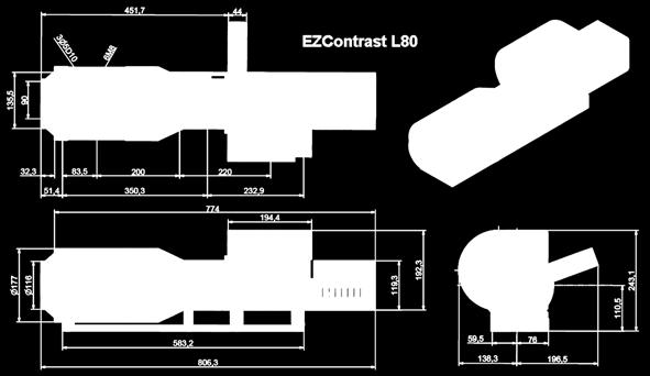

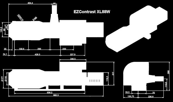
15 Outer dimension (unit mm) EZCo n t r a s t EZContrastXL88W EZContrastL80 EZLite 15
16 EZCo n t r a s t Major specifications of instruments Common specifications EZLite EZContrast L80 L80W XL88 XL88W Field coverage Incident angle Azimuth angle Measuring area Maximum diameter Minimum diameter Number of diameters Selection mode 2mm 83µm No limit Manual 2mm 100µm 5 Automated 6mm 300µm 4 Automated 2mm 100µm 5 Automated 6mm 500µm 4 Automated Optimum distance Ensure light coming from same spot at any angle 4.5mm 3.7mm 2.5mm 1mm Sensor Peltier cooled CCD grade 1 Resolution A/D converter 1.5M bits 6M bits 16M bits 6M bits 16M bits Chromaticity Color Filters Additional Filters 5 (* 1 ) Any type 5 (* 1 ) 3 possible 5 (* 1 ) No 5 (* 1 ) 3 possible 5 (* 1 ) No Neutral densities For luminance adjustment Selection mode On request Manual 0.5, 1, 2, 3 Automated Polarizing elements For polarization measurements 3 pol, 2WP Manual 3 pol, 2WP Automated Not available 3 pol, 2WP Automated Not available Reflective options Collimated & diffused Available Available Not available Available Not available Spot viewer For position adjustment B&W BNC Color CMOS camera, USB 2.0 interface Interface USB 2.0 Measurement Modes Luminance Chromaticity Polarization (option), Manual, Auto No, Auto No Luminance Range Minimum (cd/m2) Maximum (cd/m2) Maximum with density (option) (* 2 ) (* 2 ) (* 2 ) (* 2 ) (* 2 ) Accuracy Angular position Angular resolution Luminance Chromaticity (x,y) RMS Stokes vector (option) ±0.2 ±0.75 ±3% (* 3 ) (* 4 ) ±3% (* 5 ) ±0.3 ±0.3 ±3% (* 3 ) (* 4 ) ±3% (* 5 ) ±0.2 ±0.2 ±3% (* 3 ) (* 4 ) ±3% (* 5 ) ±0.3 ±0.3 ±3% (* 3 ) (* 4 ) ±3% (* 5 ) ±0.2 ±0.2 ±3% (* 3 ) (* 4 ) ±3% (* 5 ) Repeatability Luminance Chromaticity (x,y) RMS Stokes vector (option) (* 6 ) (* 6 ) (* 6 ) (* 6 ) (* 6 ) Measurement time Luminance Chromaticity Polarization (option) < 10s (* 7 ) <30s (* 7 ) Manual < 10s (* 7 ) <20s (* 7 ) <90s (* 7 ) < 10s (* 7 ) <25s (* 7 ) <90s (* 7 ) < 10s (* 7 ) <20s (* 7 ) <90s (* 7 ) < 10s (* 7 ) <25s (* 7 ) <90s (* 7 ) condition Temperature range standard Temperature range (option) Humidity range (non condensing) 0 to 40 C No 0 to 60% 0 to 40 C -30 to 80 C 0 to 85% 0 to 40 C -30 to 80 C 0 to 85% 0 to 40 C -30 to 80 C 0 to 85% 0 to 40 C -30 to 80 C 0 to 85% Power Supply 110V - 200V Consumption 90W Weight (* 1 ) All the systems use 5 color filters matched on the CCD response (2 for X, 2 for Y and 1 for Z) (* 2 ) Maximum luminance is given for the maximum spot diameter (* 3 ) The accuracy is guarantied for any type of color stimuli in contrast to competitors that generally guaranty only reference white. (* 4 ) For A type illuminant (* 5 ) For a radiance level higher than 10mW/Sr/m 2 /nm (* 6 ) For a luminance higher than 50Cd/m 2. This repeatability is given for full resolution. When a binning level N is used it is divided by a factor of N2. With standard CCD sensor and for a resolution of 375x250 the luminance repeatability is only ±0.03%! (* 7 ) Measurement times are highly dependent on the target and on the conditions. Given times are for a source with luminance level higher than 50Cd/m 2 or a radiance level higher than 10mW/Sr/m 2 /nm and already determined exposition times for all the filters. Specifications can be changed without notice Weight Height Width Length 7Kg 217mm 210mm 433mm 44Kg 243mm 335mm 671mm 52Kg 243mm 335mm 695mm 44Kg 243mm 214mm 784mm 52Kg 268mm 234mm 903mm RA-01 V3.0 05/2009 ELDIM S.A. 16
Mu lt i s p e c t r a l
 Viewing Angle Analyser Revolutionary system for full spectral and polarization measurement in the entire viewing angle EZContrastMS80 & EZContrastMS88 ADVANCED LIGHT ANALYSIS by Field iris Fourier plane
Council for Optical Radiation Measurements (CORM) 2016 Annual Technical Conference May 15 18, 2016, Gaithersburg, MD
 2016 Annual Technical Conference May 15 18, 2016, Gaithersburg, MD") Council for Optical Radiation Measurements (CORM) 2016 Annual Technical Conference May 15 18, 2016, Gaithersburg, MD Multispectral measurements of emissive and reflective properties of displays: Application
Council for Optical Radiation Measurements (CORM) 2016 Annual Technical Conference May 15 18, 2016, Gaithersburg, MD Multispectral measurements of emissive and reflective properties of displays: Application
Reflective Illumination for DMS 803 / 505
 APPLICATION NOTE // Dr. Michael E. Becker Reflective Illumination for DMS 803 / 505 DHS, SDR, VADIS, PID & PLS The instruments of the DMS 803 / 505 series are precision goniometers for directional scanning
Optical characterization of auto-stereoscopic 3D displays: interest of the resolution and comparison to human eye properties
 Optical characterization of auto-stereoscopic 3D displays: interest of the resolution and comparison to human eye properties Pierre Boher, Thierry Leroux, Thibault Bignon, Véronique Collomb-Patton ELDIM,
Light Tec Scattering measurements guideline
 Light Tec Scattering measurements guideline 1 Our Laboratory Light Tec is equipped with a Photometric Laboratory (a dark room) including: Goniophotometers: REFLET 180S. High specular bench (10 meters),
Light Tec Scattering measurements guideline
 Light Tec Scattering measurements guideline 1 Our Laboratory Light Tec is equipped with a Photometric Laboratory (a dark room) including: Goniophotometers: REFLET 180S. High specular bench (10 meters),
Light Tec Scattering measurements guideline
 Light Tec Scattering measurements guideline 1 2 Light Tec Locations REFLET assembling plant, Aix-en-Provence, France Light Tec GmbH, Munich, Germany German office Light Tec Sarl, Hyères, France Main office
Imaging Sphere Measurement of Luminous Intensity, View Angle, and Scatter Distribution Functions
 Imaging Sphere Measurement of Luminous Intensity, View Angle, and Scatter Distribution Functions Hubert Kostal, Vice President of Sales and Marketing Radiant Imaging, Inc. 22908 NE Alder Crest Drive, Suite
Published online: 30 Sep 2014.
 This article was downloaded by: [P. Boher] On: 02 October 2014, At: 23:07 Publisher: Taylor & Francis Informa Ltd Registered in England and Wales Registered Number: 1072954 Registered office: Mortimer
Light Tec Scattering measurements guideline
 Light Tec Scattering measurements guideline 1 Our Laboratory Light Tec is equipped with a Photometric Laboratory (a dark room) including: Goniophotometers: REFLET180s. High specular bench (10 meters),
Scattering measurements. Guidelines for measurements service
 Scattering measurements Guidelines for measurements service 1 Content Introduction Light Tec Presentation Instruments availalable. Scattering measurements Refelctors Diffusers Colors issuses Volume Scattering
Understanding Variability
 Understanding Variability Why so different? Light and Optics Pinhole camera model Perspective projection Thin lens model Fundamental equation Distortion: spherical & chromatic aberration, radial distortion
Physical Optics. You can observe a lot just by watching. Yogi Berra ( )
") Physical Optics You can observe a lot just by watching. Yogi Berra (1925-2015) OBJECTIVES To observe some interference and diffraction phenomena with visible light. THEORY In a previous experiment you
Physical Optics You can observe a lot just by watching. Yogi Berra (1925-2015) OBJECTIVES To observe some interference and diffraction phenomena with visible light. THEORY In a previous experiment you
DMS 201 FEATURES LOW-COST MANUAL GONIOMETER SYSTEM
 light measurement DMS 201 LOW-COST MANUAL GONIOMETER SYSTEM Turnkey solution for electrooptical display characterization for quality control, research and development. FEATURES Measurement and evaluation
Validation of the Gonioreflectometer
 Validation of the Gonioreflectometer Hongsong Li Kenneth E. Torrance PCG-03-2 May 21, 2003 i Abstract This report describes a series of experiments conducted in the Light Measurement Laboratory of the
MODELING LED LIGHTING COLOR EFFECTS IN MODERN OPTICAL ANALYSIS SOFTWARE LED Professional Magazine Webinar 10/27/2015
 MODELING LED LIGHTING COLOR EFFECTS IN MODERN OPTICAL ANALYSIS SOFTWARE LED Professional Magazine Webinar 10/27/2015 Presenter Dave Jacobsen Senior Application Engineer at Lambda Research Corporation for
Chapter 26 Geometrical Optics
 Chapter 26 Geometrical Optics 26.1 The Reflection of Light 26.2 Forming Images With a Plane Mirror 26.3 Spherical Mirrors 26.4 Ray Tracing and the Mirror Equation 26.5 The Refraction of Light 26.6 Ray
NEW OPTICAL MEASUREMENT TECHNIQUE FOR SI WAFER SURFACE DEFECTS USING ANNULAR ILLUMINATION WITH CROSSED NICOLS
 NEW OPTICAL MEASUREMENT TECHNIQUE FOR SI WAFER SURFACE DEFECTS USING ANNULAR ILLUMINATION WITH CROSSED NICOLS Satoru Takahashi 1, Takashi Miyoshi 1, Yasuhiro Takaya 1, and Takahiro Abe 2 1 Department of
Diffraction. Single-slit diffraction. Diffraction by a circular aperture. Chapter 38. In the forward direction, the intensity is maximal.
 Diffraction Chapter 38 Huygens construction may be used to find the wave observed on the downstream side of an aperture of any shape. Diffraction The interference pattern encodes the shape as a Fourier
DMS 803 FEATURES OPTIONS GONIOMETER SYSTEM FOR COMPLETE DISPLAY CHARACTERIZATION
 GONIOMETER SYSTEM FOR COMPLETE DISPLAY CHARACTERIZATION Turnkey solution with motorized scanning for detailed electro-optical display characterization for quality control, research and development. FEATURES
PHYSICS. Chapter 34 Lecture FOR SCIENTISTS AND ENGINEERS A STRATEGIC APPROACH 4/E RANDALL D. KNIGHT
 PHYSICS FOR SCIENTISTS AND ENGINEERS A STRATEGIC APPROACH 4/E Chapter 34 Lecture RANDALL D. KNIGHT Chapter 34 Ray Optics IN THIS CHAPTER, you will learn about and apply the ray model of light Slide 34-2
Display system analysis with critical polarization elements in a nonsequential ray tracing environment
 Copyright 2008, Society of Photo-Optical Instrumentation Engineers (SPIE). This paper was published in the proceedings of the August 2008 SPIE Annual Meeting and is made available as an electronic reprint
WHITE PAPER. Application of Imaging Sphere for BSDF Measurements of Arbitrary Materials
 Application of Imaging Sphere for BSDF Measurements of Arbitrary Materials Application of Imaging Sphere for BSDF Measurements of Arbitrary Materials Abstract BSDF measurements are broadly applicable to
Mode-Field Diameter and Spot Size Measurements of Lensed and Tapered Specialty Fibers
 Mode-Field Diameter and Spot Size Measurements of Lensed and Tapered Specialty Fibers By Jeffrey L. Guttman, Ph.D., Director of Engineering, Ophir-Spiricon Abstract: The Mode-Field Diameter (MFD) and spot
PHOTOMETER. Instruction Sheet for the PASCO Model OS Introduction. Equipment. How to Use the Photometer. Photometer
 Instruction Sheet for the PASCO Model OS-8520 PHOTOMETER 012-05631A 3/95 $1.00 Neutral Density Filter Introduction The PASCO OS-8520 Photometer is a non-electric comparative instrument which was designed
2/26/2016. Chapter 23 Ray Optics. Chapter 23 Preview. Chapter 23 Preview
 Chapter 23 Ray Optics Chapter Goal: To understand and apply the ray model of light. Slide 23-2 Chapter 23 Preview Slide 23-3 Chapter 23 Preview Slide 23-4 1 Chapter 23 Preview Slide 23-5 Chapter 23 Preview
Chapter 36. Image Formation
 Chapter 36 Image Formation Apr 22, 2012 Light from distant things We learn about a distant thing from the light it generates or redirects. The lenses in our eyes create images of objects our brains can
Final Exam. Today s Review of Optics Polarization Reflection and transmission Linear and circular polarization Stokes parameters/jones calculus
 Physics 42200 Waves & Oscillations Lecture 40 Review Spring 206 Semester Matthew Jones Final Exam Date:Tuesday, May 3 th Time:7:00 to 9:00 pm Room: Phys 2 You can bring one double-sided pages of notes/formulas.
1.! Questions about reflected intensity. [Use the formulas on p. 8 of Light.] , no matter
![1.! Questions about reflected intensity. [Use the formulas on p. 8 of Light.] , no matter](/thumbs/81/83191942.jpg "1.! Questions about reflected intensity. [Use the formulas on p. 8 of Light.] , no matter") Reading: Light Key concepts: Huygens s principle; reflection; refraction; reflectivity; total reflection; Brewster angle; polarization by absorption, reflection and Rayleigh scattering. 1.! Questions about
Reading: Light Key concepts: Huygens s principle; reflection; refraction; reflectivity; total reflection; Brewster angle; polarization by absorption, reflection and Rayleigh scattering. 1.! Questions about
4. A bulb has a luminous flux of 2400 lm. What is the luminous intensity of the bulb?
 1. Match the physical quantities (first column) with the units (second column). 4. A bulb has a luminous flux of 2400 lm. What is the luminous intensity of the bulb? (π=3.) Luminous flux A. candela Radiant
Announcements. Lighting. Camera s sensor. HW1 has been posted See links on web page for readings on color. Intro Computer Vision.
 Announcements HW1 has been posted See links on web page for readings on color. Introduction to Computer Vision CSE 152 Lecture 6 Deviations from the lens model Deviations from this ideal are aberrations
Reprint. from the Journal. of the SID
 A 23-in. full-panel-resolution autostereoscopic LCD with a novel directional backlight system Akinori Hayashi (SID Member) Tomohiro Kometani Akira Sakai (SID Member) Hiroshi Ito Abstract An autostereoscopic
Experiment 8 Wave Optics
 Physics 263 Experiment 8 Wave Optics In this laboratory, we will perform two experiments on wave optics. 1 Double Slit Interference In two-slit interference, light falls on an opaque screen with two closely
dq dt I = Irradiance or Light Intensity is Flux Φ per area A (W/m 2 ) Φ =
 Φ =") Radiometry (From Intro to Optics, Pedrotti -4) Radiometry is measurement of Emag radiation (light) Consider a small spherical source Total energy radiating from the body over some time is Q total Radiant
Radiometry (From Intro to Optics, Pedrotti -4) Radiometry is measurement of Emag radiation (light) Consider a small spherical source Total energy radiating from the body over some time is Q total Radiant
Waves & Oscillations
 Physics 42200 Waves & Oscillations Lecture 40 Review Spring 2016 Semester Matthew Jones Final Exam Date:Tuesday, May 3 th Time:7:00 to 9:00 pm Room: Phys 112 You can bring one double-sided pages of notes/formulas.
High spatial resolution measurement of volume holographic gratings
 High spatial resolution measurement of volume holographic gratings Gregory J. Steckman, Frank Havermeyer Ondax, Inc., 8 E. Duarte Rd., Monrovia, CA, USA 9116 ABSTRACT The conventional approach for measuring
All forms of EM waves travel at the speed of light in a vacuum = 3.00 x 10 8 m/s This speed is constant in air as well
 Pre AP Physics Light & Optics Chapters 14-16 Light is an electromagnetic wave Electromagnetic waves: Oscillating electric and magnetic fields that are perpendicular to the direction the wave moves Difference
2011 Optical Science & Engineering PhD Qualifying Examination Optical Sciences Track: Advanced Optics Time allowed: 90 minutes
 2011 Optical Science & Engineering PhD Qualifying Examination Optical Sciences Track: Advanced Optics Time allowed: 90 minutes Answer all four questions. All questions count equally. 3(a) A linearly polarized
specular diffuse reflection.
 Lesson 8 Light and Optics The Nature of Light Properties of Light: Reflection Refraction Interference Diffraction Polarization Dispersion and Prisms Total Internal Reflection Huygens s Principle The Nature
Cary Fiber Optic Probes
 Cary Fiber Optic Probes Fiber Optic Probes Use With Cary 50/60 Wavelength range 200-1100 nm Cary 100/300 Cary 50/60/100/300 Cary 4000/5000/6000i Fiber optic dip probe stainless steel body only Requires
Polarizers. Laser Polarizers Broadband Polarizing Beamsplitting Cubes 78 Narrowband Polarizing Beamsplitting Cubes 79
 Prisms Introduction to Right Angle Prisms 72 Quality Right Angle Prisms 73 Laboratory Quality Right Angle Prisms 73 Equilateral Prisms 74 Wedge Prisms 75 Anamorphic Prism Pair 75 Penta Prisms 76 Dove Prisms
PRESETTER SP40. Pesaro, September 2013
 Pesaro, September 2013 1 PRESETTER SP40 TECHNICAL SPECIFICATIONS: AXIS DIMENSIONS: Diameter 600mm, Height XXXX mm MAIN STRUCTURE: Entirely made in C45 medium carbon steel it ensures greater strength and
Fresnel Reflection. angle of transmission. Snell s law relates these according to the
 Fresnel Reflection 1. Reflectivity of polarized light The reflection of a polarized beam of light from a dielectric material such as air/glass was described by Augustin Jean Fresnel in 1823. While his
OPSE FINAL EXAM Fall CLOSED BOOK. Two pages (front/back of both pages) of equations are allowed.
 of equations are allowed.") CLOSED BOOK. Two pages (front/back of both pages) of equations are allowed. YOU MUST SHOW YOUR WORK. ANSWERS THAT ARE NOT JUSTIFIED WILL BE GIVEN ZERO CREDIT. ALL NUMERICAL ANSERS MUST HAVE UNITS INDICATED.
CLOSED BOOK. Two pages (front/back of both pages) of equations are allowed. YOU MUST SHOW YOUR WORK. ANSWERS THAT ARE NOT JUSTIFIED WILL BE GIVEN ZERO CREDIT. ALL NUMERICAL ANSERS MUST HAVE UNITS INDICATED.
Spherical Crystal X-ray Imaging for MTW, OMEGA, and OMEGA EP
 Spherical Crystal X-ray Imaging for MTW, OMEGA, and OMEGA EP C.STOECKL, G. FISKEL, R. K. JUNGQUIST, P. M. NILSON, AND W. THEOBALD University of Rochester, Laboratory for Laser Energetics Spherical Crystal
Spectrographs. C. A. Griffith, Class Notes, PTYS 521, 2016 Not for distribution.
 Spectrographs C A Griffith, Class Notes, PTYS 521, 2016 Not for distribution 1 Spectrographs and their characteristics A spectrograph is an instrument that disperses light into a frequency spectrum, which
Waves & Oscillations
 Physics 42200 Waves & Oscillations Lecture 41 Review Spring 2013 Semester Matthew Jones Final Exam Date:Tuesday, April 30 th Time:1:00 to 3:00 pm Room: Phys 112 You can bring two double-sided pages of
Philpot & Philipson: Remote Sensing Fundamentals Interactions 3.1 W.D. Philpot, Cornell University, Fall 12
 Philpot & Philipson: Remote Sensing Fundamentals Interactions 3.1 W.D. Philpot, Cornell University, Fall 1 3. EM INTERACTIONS WITH MATERIALS In order for an object to be sensed, the object must reflect,
Conceptual Physics Fundamentals
 Conceptual Physics Fundamentals Chapter 14: PROPERTIES OF LIGHT This lecture will help you understand: Reflection Refraction Dispersion Total Internal Reflection Lenses Polarization Properties of Light
Optimize Structured LCD Backlight Components Accurately and Quickly
 T E C H N I C A L N O T E Optimize Structured LCD Backlight Components Accurately and Quickly With TracePro Opto-Mechanical Design Software s Textured RepTile Optimization Utility TracePro s Textured RepTile
Light and Mirrors MIRRORS
 Light and Mirrors MIRRORS 1 Polarized Sunglasses- How do they work? light waves vibrate in more than one plane light waves can be made to vibrate in a single plane by use of polarizing filters. 2 polarizing
Beam Analysis Camera Based Beam Propagation Analyzer: M Automatic M 2 - at Production Speeds. Manual M 2
 3.7.1 Camera Based Beam Propagation Analyzer: M 2 ISO compliant Automatically measure your beam quality in under 1 minutes Tune your laser for best operation Specifically developed for continuous usage
Specifications: LED Ring Lights. Product Number
 1 LED Ring Lights provide direct illumination with high and even intensity on specular or opaque surfaces. Beam angle is factory adjusted according to customers demand on working distance (WD) and illuminated
Chapter 24. Wave Optics
 Chapter 24 Wave Optics Wave Optics The wave nature of light is needed to explain various phenomena Interference Diffraction Polarization The particle nature of light was the basis for ray (geometric) optics
Optics Vac Work MT 2008
 Optics Vac Work MT 2008 1. Explain what is meant by the Fraunhofer condition for diffraction. [4] An aperture lies in the plane z = 0 and has amplitude transmission function T(y) independent of x. It is
Measuring Light: Radiometry and Cameras
 Lecture 11: Measuring Light: Radiometry and Cameras Computer Graphics CMU 15-462/15-662, Fall 2015 Slides credit: a majority of these slides were created by Matt Pharr and Pat Hanrahan Simulating a pinhole
dq dt I = Irradiance or Light Intensity is Flux Φ per area A (W/m 2 ) Φ =
 Φ =") Radiometry (From Intro to Optics, Pedrotti -4) Radiometry is measurement of Emag radiation (light) Consider a small spherical source Total energy radiating from the body over some time is Q total Radiant
Radiometry (From Intro to Optics, Pedrotti -4) Radiometry is measurement of Emag radiation (light) Consider a small spherical source Total energy radiating from the body over some time is Q total Radiant
Radiance, Irradiance and Reflectance
 CEE 6100 Remote Sensing Fundamentals 1 Radiance, Irradiance and Reflectance When making field optical measurements we are generally interested in reflectance, a relative measurement. At a minimum, measurements
Dr. Larry J. Paxton Johns Hopkins University Applied Physics Laboratory Laurel, MD (301) (301) fax
 (301) fax") Dr. Larry J. Paxton Johns Hopkins University Applied Physics Laboratory Laurel, MD 20723 (301) 953-6871 (301) 953-6670 fax Understand the instrument. Be able to convert measured counts/pixel on-orbit into
Dr. Larry J. Paxton Johns Hopkins University Applied Physics Laboratory Laurel, MD 20723 (301) 953-6871 (301) 953-6670 fax Understand the instrument. Be able to convert measured counts/pixel on-orbit into
LED Ring Lights. LED Ring Lights
 1 LED Ring Lights LED Ring Lights provide direct illumination with high and even intensity for specular or opaque surfaces. Beam angle is factory adjusted according to customers demand on working distance
Rodenstock Products Photo Optics / Digital Imaging
 Go to: Apo-Sironar digital Apo-Macro-Sironar digital Apo-Sironar digital HR Lenses for Digital Professional Photography Digital photography may be superior to conventional photography if the end-product
Design Verification and Analysis Tools in TracePro. Presented by : Lambda Research Corporation 25 Porter Rd. Littleton, MA
 Design Verification and Analysis Tools in TracePro Presented by : Lambda Research Corporation 25 Porter Rd. Littleton, MA 01460 www.lambdares.com Moderator: Andy Knight Technical Sales Manager Lambda Research
(Fiber-optic Reosc Echelle Spectrograph of Catania Observatory)
") (Fiber-optic Reosc Echelle Spectrograph of Catania Observatory) The echelle spectrograph delivered by REOSC (France), was designed to work at the F/15 cassegrain focus of the 91-cm telescope. The spectrograph
(Fiber-optic Reosc Echelle Spectrograph of Catania Observatory) The echelle spectrograph delivered by REOSC (France), was designed to work at the F/15 cassegrain focus of the 91-cm telescope. The spectrograph
EDUCATIONAL SPECTROPHOTOMETER ACCESSORY KIT AND EDUCATIONAL SPECTROPHOTOMETER SYSTEM
 GAIN 0 Instruction Manual and Experiment Guide for the PASCO scientific Model OS-8537 and OS-8539 02-06575A 3/98 EDUCATIONAL SPECTROPHOTOMETER ACCESSORY KIT AND EDUCATIONAL SPECTROPHOTOMETER SYSTEM CI-6604A
Lab 5: Diffraction and Interference
 Lab 5: Diffraction and Interference Light is a wave, an electromagnetic wave, and under the proper circumstances, it exhibits wave phenomena, such as constructive and destructive interference. The wavelength
PHYSICS 213 PRACTICE EXAM 3*
 PHYSICS 213 PRACTICE EXAM 3* *The actual exam will contain EIGHT multiple choice quiz-type questions covering concepts from lecture (16 points), ONE essay-type question covering an important fundamental
Chapter 24. Wave Optics. Wave Optics. The wave nature of light is needed to explain various phenomena
 Chapter 24 Wave Optics Wave Optics The wave nature of light is needed to explain various phenomena Interference Diffraction Polarization The particle nature of light was the basis for ray (geometric) optics
PolarSpeed -S/PolarSpeed -S-AR
 LC-Tec Displays AB PolarSpeed -S/PolarSpeed -S-AR product specification February, 2016 PolarSpeed -S/PolarSpeed -S-AR PRODUCT SPECIFICATION Content 1. Revision history... 2 2. Product description... 2
Announcements. Camera Calibration. Thin Lens: Image of Point. Limits for pinhole cameras. f O Z
 Announcements Introduction to Computer Vision CSE 152 Lecture 5 Assignment 1 has been posted. See links on web page for reading Irfanview: http://www.irfanview.com/ is a good windows utility for manipulating
Design and fabrication of reflective nematic displays with only one polarizer
 Design and fabrication of reflective nematic displays with only one polarizer H. S. Kwok 1, F. H. Yu 2, S. T. Tang and J. Chen Center for Display Research and Department of Electrical and Electronic Engineering
PHYS:1200 LECTURE 32 LIGHT AND OPTICS (4)
") 1 PHYS:1200 LECTURE 32 LIGHT AND OPTICS (4) The first three lectures in this unit dealt with what is for called geometric optics. Geometric optics, treats light as a collection of rays that travel in straight
1 PHYS:1200 LECTURE 32 LIGHT AND OPTICS (4) The first three lectures in this unit dealt with what is for called geometric optics. Geometric optics, treats light as a collection of rays that travel in straight
Geometrical Optics INTRODUCTION. Wave Fronts and Rays
 Geometrical Optics INTRODUCTION In this experiment, the optical characteristics of mirrors, lenses, and prisms will be studied based on using the following physics definitions and relationships plus simple
Reflections. I feel pretty, oh so pretty
 Reflections I feel pretty, oh so pretty Objectives By the end of the lesson, you should be able to: Draw an accurate reflective angle Determine the focal length of a spherical mirror Light Review Light
INTERFERENCE. (i) When the film is quite thin as compared to the wavelength of light,
 When the film is quite thin as compared to the wavelength of light,") (a) Reflected System: For the thin film in air the ray BG suffers reflection at air medium (rare to denser) boundary, it undergoes a phase change of π and a path change of λ/2, while the ray DF does not,
(a) Reflected System: For the thin film in air the ray BG suffers reflection at air medium (rare to denser) boundary, it undergoes a phase change of π and a path change of λ/2, while the ray DF does not,
Representing the World
 Table of Contents Representing the World...1 Sensory Transducers...1 The Lateral Geniculate Nucleus (LGN)... 2 Areas V1 to V5 the Visual Cortex... 2 Computer Vision... 3 Intensity Images... 3 Image Focusing...
Micro Structures Design of OLED Tail Lamp Abstract 1. Introduction
 Micro Structures Design of OLED Tail Lamp Yao-Min Ho, Jih-Tao Hsu Automotive Research Testing Center No.6, Lugong S.7th Rd.,Lugang,Changhua County 50544,Taiwan(R.O.C) E-mail: yaomin@artc.org.tw Abstract
Ray Optics. Ray model Reflection Refraction, total internal reflection Color dispersion Lenses Image formation Magnification Spherical mirrors
 Ray Optics Ray model Reflection Refraction, total internal reflection Color dispersion Lenses Image formation Magnification Spherical mirrors 1 Ray optics Optical imaging and color in medicine Integral
FluxGage. FluxGage. LED Luminaire Measurement System User Manual
 FluxGage FluxGage LED Luminaire Measurement System User Manual 1 Acronyms... 3 2 Introduction... 4 2.1 Operation principle... 4 3 Specifications... 5 4 Mechanical and Electrical Installation... 9 4.1 Unpacking...
PHYSICS. Chapter 33 Lecture FOR SCIENTISTS AND ENGINEERS A STRATEGIC APPROACH 4/E RANDALL D. KNIGHT
 PHYSICS FOR SCIENTISTS AND ENGINEERS A STRATEGIC APPROACH 4/E Chapter 33 Lecture RANDALL D. KNIGHT Chapter 33 Wave Optics IN THIS CHAPTER, you will learn about and apply the wave model of light. Slide
WAVELENGTH MANAGEMENT
 Camera Accessories WAVELENGTH MANAGEMENT UV CONVERTERS UV Converters take advantage of a phenomenon called fluorescence to extend the performance range of the Beamage beam profiling camera to ultraviolet
The Berek Polarization Compensator Model 5540
 USER S GUIDE The Berek Polarization Compensator Model 5540 U.S. Patent # 5,245,478 3635 Peterson Way Santa Clara, CA 95054 USA phone: (408) 980-5903 fax: (408) 987-3178 e-mail: techsupport@newfocus.com
Polarization of Light
 Polarization of Light Introduction Light, viewed classically, is a transverse electromagnetic wave. Namely, the underlying oscillation (in this case oscillating electric and magnetic fields) is along directions
Light Tec. Characterization of ultra-polished surfaces in UV and IR. ICSO October 2016 Biarritz, France
 ICSO 2016 17-21 October 2016 Biarritz, France Light Tec Characterization of ultra-polished surfaces in UV and IR Quentin Kuperman, Author, Technical Manager Yan Cornil, Presenter, CEO Workshop 2016, 12/09
Range Sensors (time of flight) (1)
 (1)") Range Sensors (time of flight) (1) Large range distance measurement -> called range sensors Range information: key element for localization and environment modeling Ultrasonic sensors, infra-red sensors
Range Sensors (time of flight) (1) Large range distance measurement -> called range sensors Range information: key element for localization and environment modeling Ultrasonic sensors, infra-red sensors
Coherent Gradient Sensing Microscopy: Microinterferometric Technique. for Quantitative Cell Detection
 Coherent Gradient Sensing Microscopy: Microinterferometric Technique for Quantitative Cell Detection Proceedings of the SEM Annual Conference June 7-10, 010 Indianapolis, Indiana USA 010 Society for Experimental
FOS-NIR(1100) Content PRODUCT SPECIFICATION
 Content PRODUCT SPECIFICATION") LC-Tec Displays AB FOS-NIR(1100) product specification February, 2016 FOS-NIR(1100) PRODUCT SPECIFICATION Content 1. Revision history... 2 2. Product description... 2 3. Ordering information... 2 4. Custom
LC-Tec Displays AB FOS-NIR(1100) product specification February, 2016 FOS-NIR(1100) PRODUCT SPECIFICATION Content 1. Revision history... 2 2. Product description... 2 3. Ordering information... 2 4. Custom
Light and the Properties of Reflection & Refraction
 Light and the Properties of Reflection & Refraction OBJECTIVE To study the imaging properties of a plane mirror. To prove the law of reflection from the previous imaging study. To study the refraction
Development of Reflector for HR-TFTs
 Development of Reflector for HR-TFTs Kazuhiko Tsuda* Naofumi Kimura* Shigeaki Mizushima* * Development Department 1, Liquid Crystal Display Laboratories, Liquid Crystal Display Development Group Abstract
Application Note. Measuring the Geometric Attributes of Your Products AN
 Application Note AN 1007.01 Measuring the Geometric Attributes of Your Products Abstract Consumers have a choice and when all other factors are equal, they buy what looks best. All industries are concerned
AP Physics Problems -- Waves and Light
 AP Physics Problems -- Waves and Light 1. 1975-4 (Physical Optics) a. Light of a single wavelength is incident on a single slit of width w. (w is a few wavelengths.) Sketch a graph of the intensity as
DMS 903 FEATURES GONIOMETER SYSTEM FOR COMPLETE DISPLAY CHARACTERIZATION
 light measurement DMS 903 GONIOMETER SYSTEM FOR COMPLETE DISPLAY CHARACTERIZATION Turnkey solution with motorized scanning for detailed electrooptical display characterization of large-area displays for
Waves & Oscillations
 Physics 42200 Waves & Oscillations Lecture 41 Review Spring 2016 Semester Matthew Jones Final Exam Date:Tuesday, May 3 th Time:7:00 to 9:00 pm Room: Phys 112 You can bring one double-sided pages of notes/formulas.
Geometrical modeling of light scattering from paper substrates
 Geometrical modeling of light scattering from paper substrates Peter Hansson Department of Engineering ciences The Ångström Laboratory, Uppsala University Box 534, E-75 Uppsala, weden Abstract A light
Chapter 24. Wave Optics
 Chapter 24 Wave Optics Diffraction Huygen s principle requires that the waves spread out after they pass through slits This spreading out of light from its initial line of travel is called diffraction
TracePro Stray Light Simulation
 TracePro Stray Light Simulation What Is Stray Light? A more descriptive term for stray light is unwanted light. In an optical imaging system, stray light is caused by light from a bright source shining
Optical Ptychography Imaging
 Optical Ptychography Imaging Summer Project Annafee Azad Supervisors: Dr Fucai Zhang Prof Ian Robinson Summer 2014 23 October 2014 Optical Ptychography Imaging P a g e 2 Abstract This report details a
Optics II. Reflection and Mirrors
 Optics II Reflection and Mirrors Geometric Optics Using a Ray Approximation Light travels in a straight-line path in a homogeneous medium until it encounters a boundary between two different media The
E3S-A. Built-in Amplifier Photoelectric Sensor (Medium Size) Ordering Information. Built-in Amplifier Photoelectric Sensors. Horizontal. 7 m.
 Ordering Information. Built-in Amplifier Photoelectric Sensors. Horizontal. 7 m.") Built-in Amplifier (Medium Size) ES-A CSM_ES-A_DS_E Be sure to read Safety Precautions on page 0. Ordering Information Built-in Amplifier s Red light Infrared light Sensing method Appearance Connection
Built-in Amplifier (Medium Size) ES-A CSM_ES-A_DS_E Be sure to read Safety Precautions on page 0. Ordering Information Built-in Amplifier s Red light Infrared light Sensing method Appearance Connection
Physics 214 Midterm Fall 2003 Form A
 1. A ray of light is incident at the center of the flat circular surface of a hemispherical glass object as shown in the figure. The refracted ray A. emerges from the glass bent at an angle θ 2 with respect
MICHELSON S INTERFEROMETER
 MICHELSON S INTERFEROMETER Objectives: 1. Alignment of Michelson s Interferometer using He-Ne laser to observe concentric circular fringes 2. Measurement of the wavelength of He-Ne Laser and Na lamp using