MEEN 3360 Engineering Design and Simulation Spring 2016 Homework #1 This homework is due Tuesday, February 2, From your book and other
|
|
|
- Robert Wright
- 5 years ago
- Views:
Transcription
1 MEEN 3360 Engineering Design and Simulation Spring 2016 Homework #1 This homework is due Tuesday, February 2, From your book and other sources, write a paragraph explaining CFD and finite element analysis are and how they are used. 2.0 Discuss the importance of the matrix equation F=KX, and how we can solve it computationally. 3.0 On the SolidWorks site (solidworks.com), click on /Products/Simulation. Read about these tools. Give a brief description of SolidWorks Simulation Premium and SolidWorks Flow Simulation. 4.0 Go to the ANSYS web site and read about ANSYS Mechanical and ANSYS Workbench. Briefly describe what they do, and how we could use them in this course. We have an ANSYS academic package, as described in Product-Portfolio available on campus. 5.0 I strongly recommend that you download and install the free ANSYS Student, from here: Search on the web, on asme.net, in the library, and elsewhere for the names and descriptions of various finite element and CFD analysis packages. Examples are MSC-NASTRAN, ADINA, FLUENT. Find 4 each of general purpose, dynamic analysis, and fluid (CFD) analysis packages (besides the ones mentioned above). Give the names of each, a web address, and a short description word description. Type these up and send to me in an Not including the packages in 4.0, find 6 shareware or demonstration Structural Finite Element Analysis (FEA) packages, list their web addresses and stipulations for use. Note that 3-D graphics, computational fluid dynamics (CFD), meshing, and solid modeling software are different than finite element analysis (FEA) packages, and do not count. Please type the answer or results of each item above, using a word processor, with your name and address at the top, hand it in, and also send it in an to Larry.Peel@tamuk.edu. I will compile all of the web addresses and send a more complete list back to you.
2 Review Problems: 7.0 For the following figure: a) find the maximum normal force, N x, max shear force in the y- z plane, and the maximum moment as a vector quantity at the fixed end of the pipe, b) Using the above numbers, determine σ x max τ xy max at the positive y side of the pipe. Assume that the external diameter is 40 mm, and pipe thickness is 4 mm.
3 8.0 The following represents a semi end-dump trailer. It is 40 ft long, is raised to an angle of 45 degrees, has a distributed load of 100 lbs/in that represents its load and weight, and has a pressure of 0.1 psi acting in the +y direction, on the side of the trailer. a) find the maximum normal force, N z, max shear force in the x-y plane, and the maximum vector moment at the fixed end (A) of the hydraulic cylinder, b) Using the above numbers, determine σ z max τ xy max on the cylinder. Assume that the external diameter is 8 in, and pipe thickness is 0.5 in.
4 9.0 For the following chart, with f(x) given and a line at y=14, determine how you could numerically or computationally find the coordinates of their intersection (x,y). Show me your logic, and sketch how you would converge on a result. f(x) f(x)=x 2-2x X values


5 What is Finite Element Analysis (FEA)? A computerized or automated method for predicting how a component will react to external forces, moments, heat, vibration, and so on. The first part of this course will concentrate on structural FEA
6 For Structural FEA the basic equation is F= force vector K = stiffness matrix X = displacement vector F=KX, What would K be for a cantilever beam with a force on the end? (δ = PL 3 / 3EI)
7 Basic FEA Theory (4.1) Where {F} is a vector representing forces acting on the nodes in a structure, {U} is the displacement vector for each degree of freedom of the nodes (translation and rotation). The matrix [K] is known as the stiffness matrix and is dependent upon the physical characteristics of the elements including shape, size, and the Young s Modulus of the material the element is to represent. Figure 4.2 shows how a simple beam can be represented as a spring with stiffness [K] from which the displacement {U} can be solved when {F} is applied to the end. = Figure 4.1 Simple fixed beam analyzed as a simple spring with stiffness K. The analytical solution for the displacement U from solid mechanics is
8 Where A is the cross-section area of the beam and E is its Young s Modulus. In order to utilize Hooks Law, when Equation 4.2 is solved for F in terms of U, the following result is obtained, (4.2) (4.3) resulting in (4.3b) Equations 4.2 through 4.3a 4.3b describe a simple situation for which a set of scalar equations are suitable to solve for the displacement of the single node in the system. When more complicated systems are analyzed, the one in Figure 4.3 can be formed with multiple nodes and forces. Then Equations must be written in matrix notation. Figure 4.2 A Slightly more complex element that contains two nodes with still only 1 DOF for which matrix notation must be used.
9 Hook s Law is used to solve F 1 at node 1 and is defined as follows: Assuming equilibrium, F 2 can be solved: (4.4) (4.4b) Now that F 1 and F 2 have been defined, Equation 4.1 can be expressed in matrix form. Equation 4.5 accurately describes the relationship between {F},[K], and {U} for a single element, but FEA involves working with a network of elements with varying {F} and [K] values that share common nodes. Figure 4.4 shows a multi-spring structure that illustrates this concept. (4.5) Figure 4.3 System of elements with different K values that share node 2. Here two elements with different K values share node 2. To solve this problem the same approach used to obtain Equations 4.4a and 4.4b is used. By applying Hooks Law to all three nodes the following relationships are obtained.
10 (4.6a) (4.6b) (4.6c) Rewriting in matrix form yields: (4.7) The [K] matrix in Equation 4.7 is referred to as the Global Stiffness Matrix (GSM) and in this case {U} can easily be solved, given that the values for {F} and [K} are known. This is done by inverting [K] and performing a matrix multiplication operation with {F}. Such a procedure is an option for solving for the unknown displacement {U} when the GSM is relatively small but it is important to understand that the size of this matrix increases dramatically as the system becomes more complex. The size of the GSM is equal to the number of nodes times the number of degrees of freedom. In the example shown in Figure 4.4, there were 3 nodes with only a translational displacement in one direction will yield a 3 X 3 GSM. This can easily be solved by hand, but for a system with 1,000 nodes that allows for translation and rotation in X,Y and Z directions, will produce a 6,000 x 6,000 GSM. A matrix of this size cannot be solved by hand.
 The geometry may be modified or simplified from what the")

11 How FEA works: A component is created in a CAD package (2-d or 3-d) The geometry may be modified or simplified from what the original drawing shows The component is then meshed or broken into small or finite chunks or elements. Loads and constraints are applied.

12 An analysis is run, and force/stress/deflection results are displayed graphically or numerically.


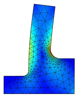
13 Other Examples of Finite Element Meshes and Results Curved Mesh Mesh-less FEA Adaptive Meshing ( s=ind_183%2caid_278873&doc_id=278873&image_number=1)

14 Cool Stuff This is a meshing and FEA problem involving twisted fibers/wires that I am working on.
Visit the following websites to learn more about this book:
 Visit the following websites to learn more about this book: 6 Introduction to Finite Element Simulation Historically, finite element modeling tools were only capable of solving the simplest engineering
CITY AND GUILDS 9210 UNIT 135 MECHANICS OF SOLIDS Level 6 TUTORIAL 15 - FINITE ELEMENT ANALYSIS - PART 1
 Outcome 1 The learner can: CITY AND GUILDS 9210 UNIT 135 MECHANICS OF SOLIDS Level 6 TUTORIAL 15 - FINITE ELEMENT ANALYSIS - PART 1 Calculate stresses, strain and deflections in a range of components under
ME 345: Modeling & Simulation. Introduction to Finite Element Method
 ME 345: Modeling & Simulation Introduction to Finite Element Method Examples Aircraft 2D plate Crashworthiness 2 Human Heart Gears Structure Human Spine 3 F.T. Fisher, PhD Dissertation, 2002 Fluid Flow
An Overview of Computer Aided Design and Finite Element Analysis
 An Overview of Computer Aided Design and Finite Element Analysis by James Doane, PhD, PE Contents 1.0 Course Overview... 4 2.0 General Concepts... 4 2.1 What is Computer Aided Design... 4 2.1.1 2D verses
NEW WAVE OF CAD SYSTEMS AND ITS APPLICATION IN DESIGN
 Vol 4 No 3 NEW WAVE OF CAD SYSTEMS AND ITS APPLICATION IN DESIGN Ass Lecturer Mahmoud A Hassan Al-Qadisiyah University College of Engineering hasaaneng@yahoocom ABSTRACT This paper provides some lighting
ANSYS AIM Tutorial Structural Analysis of a Plate with Hole
 ANSYS AIM Tutorial Structural Analysis of a Plate with Hole Author(s): Sebastian Vecchi, ANSYS Created using ANSYS AIM 18.1 Problem Specification Pre-Analysis & Start Up Analytical vs. Numerical Approaches
Global to Local Model Interface for Deepwater Top Tension Risers
 Global to Local Model Interface for Deepwater Top Tension Risers Mateusz Podskarbi Karan Kakar 2H Offshore Inc, Houston, TX Abstract The water depths from which oil and gas are being produced are reaching
Revised Sheet Metal Simulation, J.E. Akin, Rice University
 Revised Sheet Metal Simulation, J.E. Akin, Rice University A SolidWorks simulation tutorial is just intended to illustrate where to find various icons that you would need in a real engineering analysis.
Finite Element Analysis Using Creo Simulate 4.0
 Introduction to Finite Element Analysis Using Creo Simulate 4.0 Randy H. Shih SDC PUBLICATIONS Better Textbooks. Lower Prices. www.sdcpublications.com Powered by TCPDF (www.tcpdf.org) Visit the following
ANSYS Workbench Guide
 ANSYS Workbench Guide Introduction This document serves as a step-by-step guide for conducting a Finite Element Analysis (FEA) using ANSYS Workbench. It will cover the use of the simulation package through
The part to be analyzed is the bracket from the tutorial of Chapter 3.
 Introduction to Solid Modeling Using SolidWorks 2007 COSMOSWorks Tutorial Page 1 In this tutorial, we will use the COSMOSWorks finite element analysis (FEA) program to analyze the response of a component
 Set No. 1 IV B.Tech. I Semester Regular Examinations, November 2010 FINITE ELEMENT METHODS (Mechanical Engineering) Time: 3 Hours Max Marks: 80 Answer any FIVE Questions All Questions carry equal marks
Revision of the SolidWorks Variable Pressure Simulation Tutorial J.E. Akin, Rice University, Mechanical Engineering. Introduction
 Revision of the SolidWorks Variable Pressure Simulation Tutorial J.E. Akin, Rice University, Mechanical Engineering Introduction A SolidWorks simulation tutorial is just intended to illustrate where to
General modeling guidelines
 General modeling guidelines Some quotes from industry FEA experts: Finite element analysis is a very powerful tool with which to design products of superior quality. Like all tools, it can be used properly,
ME Optimization of a Frame
 ME 475 - Optimization of a Frame Analysis Problem Statement: The following problem will be analyzed using Abaqus. 4 7 7 5,000 N 5,000 N 0,000 N 6 6 4 3 5 5 4 4 3 3 Figure. Full frame geometry and loading
Finite Element Analysis using ANSYS Mechanical APDL & ANSYS Workbench
 Finite Element Analysis using ANSYS Mechanical APDL & ANSYS Workbench Course Curriculum (Duration: 120 Hrs.) Section I: ANSYS Mechanical APDL Chapter 1: Before you start using ANSYS a. Introduction to
Guidelines for proper use of Plate elements
 Guidelines for proper use of Plate elements In structural analysis using finite element method, the analysis model is created by dividing the entire structure into finite elements. This procedure is known
Pro MECHANICA STRUCTURE WILDFIRE 4. ELEMENTS AND APPLICATIONS Part I. Yves Gagnon, M.A.Sc. Finite Element Analyst & Structural Consultant SDC
 Pro MECHANICA STRUCTURE WILDFIRE 4 ELEMENTS AND APPLICATIONS Part I Yves Gagnon, M.A.Sc. Finite Element Analyst & Structural Consultant SDC PUBLICATIONS Schroff Development Corporation www.schroff.com
FB-MULTIPIER vs ADINA VALIDATION MODELING
 FB-MULTIPIER vs ADINA VALIDATION MODELING 1. INTRODUCTION 1.1 Purpose of FB-MultiPier Validation testing Performing validation of structural analysis software delineates the capabilities and limitations
Shell-to-Solid Element Connector(RSSCON)
") WORKSHOP 11 Shell-to-Solid Element Connector(RSSCON) Solid Shell MSC.Nastran 105 Exercise Workbook 11-1 11-2 MSC.Nastran 105 Exercise Workbook WORKSHOP 11 Shell-to-Solid Element Connector The introduction
WORKSHOP 11 Shell-to-Solid Element Connector(RSSCON) Solid Shell MSC.Nastran 105 Exercise Workbook 11-1 11-2 MSC.Nastran 105 Exercise Workbook WORKSHOP 11 Shell-to-Solid Element Connector The introduction
COMPUTER AIDED ENGINEERING. Part-1
 COMPUTER AIDED ENGINEERING Course no. 7962 Finite Element Modelling and Simulation Finite Element Modelling and Simulation Part-1 Modeling & Simulation System A system exists and operates in time and space.
Chapter 1 Introduction
 Chapter 1 Introduction GTU Paper Analysis (New Syllabus) Sr. No. Questions 26/10/16 11/05/16 09/05/16 08/12/15 Theory 1. What is graphic standard? Explain different CAD standards. 2. Write Bresenham s
Finite Element Course ANSYS Mechanical Tutorial Tutorial 3 Cantilever Beam
 Problem Specification Finite Element Course ANSYS Mechanical Tutorial Tutorial 3 Cantilever Beam Consider the beam in the figure below. It is clamped on the left side and has a point force of 8kN acting
ixcube 4-10 Brief introduction for membrane and cable systems.
 ixcube 4-10 Brief introduction for membrane and cable systems. ixcube is the evolution of 20 years of R&D in the field of membrane structures so it takes a while to understand the basic features. You must
ANSYS Element. elearning. Peter Barrett October CAE Associates Inc. and ANSYS Inc. All rights reserved.
 ANSYS Element Selection elearning Peter Barrett October 2012 2012 CAE Associates Inc. and ANSYS Inc. All rights reserved. ANSYS Element Selection What is the best element type(s) for my analysis? Best
Final project: Design problem
 ME309 Homework #5 Final project: Design problem Select one of the analysis problems listed below to solve. Your solution, along with a description of your analysis process, should be handed in as a final
Engineering Effects of Boundary Conditions (Fixtures and Temperatures) J.E. Akin, Rice University, Mechanical Engineering
 J.E. Akin, Rice University, Mechanical Engineering") Engineering Effects of Boundary Conditions (Fixtures and Temperatures) J.E. Akin, Rice University, Mechanical Engineering Here SolidWorks stress simulation tutorials will be re-visited to show how they
Engineering Effects of Boundary Conditions (Fixtures and Temperatures) J.E. Akin, Rice University, Mechanical Engineering Here SolidWorks stress simulation tutorials will be re-visited to show how they
Exercise 2: Mesh Resolution, Element Shapes, Basis Functions & Convergence Analyses
 Exercise 2: Mesh Resolution, Element Shapes, Basis Functions & Convergence Analyses Goals In this exercise, we will explore the strengths and weaknesses of different element types (tetrahedrons vs. hexahedrons,
Analysis of fluid-solid coupling vibration characteristics of probe based on ANSYS Workbench
 Analysis of fluid-solid coupling vibration characteristics of probe based on ANSYS Workbench He Wang 1, a, Changzheng Zhao 1, b and Hongzhi Chen 1, c 1 Shandong University of Science and Technology, Qingdao
ES 230 Strengths Intro to Finite Element Modeling & Analysis Homework Assignment 5
 ES 230 Strengths Intro to Finite Element Modeling & Analysis Homework Assignment 5 The GREAT Combined Load Problem Moving on to Principal Stresses and von Mises Failure Criteria Open up your ANSYS model
Lecturer: Lars Andersen, MSc, PhD, Associate Professor Department of Civil Engineering, Division of Structural Mechanics
 Purpose of the Course 1 Lecturer: Lars Andersen, MSc, PhD, Associate Professor Department of Civil Engineering, Division of Structural Mechanics Aalborg University, it Sohngaardsholmsvej h 57, DK-9000
Introduction to Finite Element Analysis using ANSYS
 Introduction to Finite Element Analysis using ANSYS Sasi Kumar Tippabhotla PhD Candidate Xtreme Photovoltaics (XPV) Lab EPD, SUTD Disclaimer: The material and simulations (using Ansys student version)
Design and development of optimized sprocket for Track hoe
 Design and development of optimized sprocket for Track hoe Mr. Laxmikant P.Sutar 1, Prof. Prashant.G. Karajagi 2, Prof. Rahul Kulkarni 3 1 PG Student, Siddhant College of Engineering, Pune, India 2 Assistant
CHAPTER 5 FINITE ELEMENT METHOD
 CHAPTER 5 FINITE ELEMENT METHOD 5.1 Introduction to Finite Element Method Finite element analysis is a computer based numerical method to deduce engineering structures strength and behaviour. Its use can
Simulation of Turbulent Flow around an Airfoil
 1. Purpose Simulation of Turbulent Flow around an Airfoil ENGR:2510 Mechanics of Fluids and Transfer Processes CFD Lab 2 (ANSYS 17.1; Last Updated: Nov. 7, 2016) By Timur Dogan, Michael Conger, Andrew
Generative Part Structural Analysis Fundamentals
 CATIA V5 Training Foils Generative Part Structural Analysis Fundamentals Version 5 Release 19 September 2008 EDU_CAT_EN_GPF_FI_V5R19 About this course Objectives of the course Upon completion of this course
Module 1: Introduction to Finite Element Analysis. Lecture 4: Steps in Finite Element Analysis
 25 Module 1: Introduction to Finite Element Analysis Lecture 4: Steps in Finite Element Analysis 1.4.1 Loading Conditions There are multiple loading conditions which may be applied to a system. The load
Finite Element Analysis Dr. B. N. Rao Department of Civil Engineering Indian Institute of Technology Madras. Module - 01 Lecture - 15
 Finite Element Analysis Dr. B. N. Rao Department of Civil Engineering Indian Institute of Technology Madras Module - 01 Lecture - 15 In the last class we were looking at this 3-D space frames; let me summarize
2008 International ANSYS Conference
 2008 International ANSYS Conference FEM AND FSI SIMULATIONS OF IMPACT LOADS ON GRP SUBSEA COMPOSITE COVERS Kjetil Rognlien, MSc Technical Consultant EDR AS, Norway 2008 ANSYS, Inc. All rights reserved.
Element Order: Element order refers to the interpolation of an element s nodal results to the interior of the element. This determines how results can
 TIPS www.ansys.belcan.com 鲁班人 (http://www.lubanren.com/weblog/) Picking an Element Type For Structural Analysis: by Paul Dufour Picking an element type from the large library of elements in ANSYS can be
NUMERICAL ANALYSIS OF ENGINEERING STRUCTURES (LINEAR ELASTICITY AND THE FINITE ELEMENT METHOD)
") NUMERICAL ANALYSIS OF ENGINEERING STRUCTURES (LINEAR ELASTICITY AND THE FINITE ELEMENT METHOD) NUMERICAL ANALYSIS OF ENGINEERING STRUCTURES (LINEAR ELASTICITY AND THE FINITE ELEMENT METHOD) Author: Tamás
NUMERICAL ANALYSIS OF ENGINEERING STRUCTURES (LINEAR ELASTICITY AND THE FINITE ELEMENT METHOD) NUMERICAL ANALYSIS OF ENGINEERING STRUCTURES (LINEAR ELASTICITY AND THE FINITE ELEMENT METHOD) Author: Tamás
ANSYS AIM Tutorial Stepped Shaft in Axial Tension
 ANSYS AIM Tutorial Stepped Shaft in Axial Tension Author(s): Sebastian Vecchi, ANSYS Created using ANSYS AIM 18.1 Contents: Problem Specification 3 Learning Goals 4 Pre-Analysis & Start Up 5 Calculation
3D Finite Element Software for Cracks. Version 3.2. Benchmarks and Validation
 3D Finite Element Software for Cracks Version 3.2 Benchmarks and Validation October 217 1965 57 th Court North, Suite 1 Boulder, CO 831 Main: (33) 415-1475 www.questintegrity.com http://www.questintegrity.com/software-products/feacrack
Non-Linear Finite Element Methods in Solid Mechanics Attilio Frangi, Politecnico di Milano, February 3, 2017, Lesson 1
 Non-Linear Finite Element Methods in Solid Mechanics Attilio Frangi, attilio.frangi@polimi.it Politecnico di Milano, February 3, 2017, Lesson 1 1 Politecnico di Milano, February 3, 2017, Lesson 1 2 Outline
Module 1.3W Distributed Loading of a 1D Cantilever Beam
 Module 1.3W Distributed Loading of a 1D Cantilever Beam Table of Contents Page Number Problem Description 2 Theory 2 Workbench Analysis System 4 Engineering Data 5 Geometry 6 Model 11 Setup 13 Solution
ME 442. Marc/Mentat-2011 Tutorial-1
 ME 442 Overview Marc/Mentat-2011 Tutorial-1 The purpose of this tutorial is to introduce the new user to the MSC/MARC/MENTAT finite element program. It should take about one hour to complete. The MARC/MENTAT
Solid and shell elements
 Solid and shell elements Theodore Sussman, Ph.D. ADINA R&D, Inc, 2016 1 Overview 2D and 3D solid elements Types of elements Effects of element distortions Incompatible modes elements u/p elements for incompressible
ASSIGNMENT 1 INTRODUCTION TO CAD
 Computer Aided Design(2161903) ASSIGNMENT 1 INTRODUCTION TO CAD Theory 1. Discuss the reasons for implementing a CAD system. 2. Define computer aided design. Compare computer aided design and conventional
Modeling Bolted Connections. Marilyn Tomlin CAE COE / Siemens Corporation
 Modeling Bolted Connections Marilyn Tomlin CAE COE / Siemens Corporation Overview Bolted Connection Engineering Judgment Modeling Options Summary Typical Bolted Connection Gasket Bolt Nut Washer Technology
ES 230 Strengths Intro to Finite Element Modeling & Analysis Homework Assignment 2
 ES 230 Strengths Intro to Finite Element Modeling & Analysis Homework Assignment 2 In this homework assignment you will use your rapidly developing ANSYS skill set to model and analyze three different
3D SolidWorks Tutorial
 ROCHESTER INSTITUTE OF TECHNOLOGY MICROELECTRONIC ENGINEERING 3D SolidWorks Tutorial Dr. Lynn Fuller webpage: http://people.rit.edu/lffeee Electrical and Microelectronic Engineering Rochester Institute
Creo Simulate 3.0 Tutorial
 Creo Simulate 3.0 Tutorial Structure and Thermal Roger Toogood, Ph.D., P. Eng. SDC PUBLICATIONS Better Textbooks. Lower Prices. www.sdcpublications.com Powered by TCPDF (www.tcpdf.org) Visit the following
[3] Rigid Body Analysis
![[3] Rigid Body Analysis](/thumbs/92/109073357.jpg "[3] Rigid Body Analysis") [3] Rigid Body Analysis Page 1 of 53 [3] Rigid Body Analysis [3.1] Equilibrium of a Rigid Body [3.2] Equations of Equilibrium [3.3] Equilibrium in 3-D [3.4] Simple Trusses [3.5] The Method of Joints [3.6]
[3] Rigid Body Analysis Page 1 of 53 [3] Rigid Body Analysis [3.1] Equilibrium of a Rigid Body [3.2] Equations of Equilibrium [3.3] Equilibrium in 3-D [3.4] Simple Trusses [3.5] The Method of Joints [3.6]
Auto Injector Syringe. A Fluent Dynamic Mesh 1DOF Tutorial
 Auto Injector Syringe A Fluent Dynamic Mesh 1DOF Tutorial 1 2015 ANSYS, Inc. June 26, 2015 Prerequisites This tutorial is written with the assumption that You have attended the Introduction to ANSYS Fluent
Chapter 3 Analysis of Original Steel Post
 Chapter 3. Analysis of original steel post 35 Chapter 3 Analysis of Original Steel Post This type of post is a real functioning structure. It is in service throughout the rail network of Spain as part
CHAPTER 1. Introduction
 ME 475: Computer-Aided Design of Structures 1-1 CHAPTER 1 Introduction 1.1 Analysis versus Design 1.2 Basic Steps in Analysis 1.3 What is the Finite Element Method? 1.4 Geometrical Representation, Discretization
300 N All lengths in meters. Step load applied at time 0.0.
 Problem description In this problem, we subject the beam structure of problem 1 to an impact load as shown. 300 N 0.02 0.02 1 All lengths in meters. Step load applied at time 0.0. E = 2.07 10 11 N/m 2
PTC Newsletter January 14th, 2002
 PTC Email Newsletter January 14th, 2002 PTC Product Focus: Pro/MECHANICA (Structure) Tip of the Week: Creating and using Rigid Connections Upcoming Events and Training Class Schedules PTC Product Focus:
Module 1.5: Moment Loading of a 2D Cantilever Beam
 Module 1.5: Moment Loading of a D Cantilever Beam Table of Contents Page Number Problem Description Theory Geometry 4 Preprocessor 7 Element Type 7 Real Constants and Material Properties 8 Meshing 9 Loads
Finite Element Analysis Using NEi Nastran
 Appendix B Finite Element Analysis Using NEi Nastran B.1 INTRODUCTION NEi Nastran is engineering analysis and simulation software developed by Noran Engineering, Inc. NEi Nastran is a general purpose finite
The Application of EXCEL in Teaching Finite Element Analysis to Final Year Engineering Students.
 The Application of EXCEL in Teaching Finite Element Analysis to Final Year Engineering Students. Kian Teh and Laurie Morgan Curtin University of Technology Abstract. Many commercial programs exist for
Introduction. Section 3: Structural Analysis Concepts - Review
 Introduction In this class we will focus on the structural analysis of framed structures. Framed structures consist of components with lengths that are significantly larger than crosssectional areas. We
Verification of Laminar and Validation of Turbulent Pipe Flows
 1 Verification of Laminar and Validation of Turbulent Pipe Flows 1. Purpose ME:5160 Intermediate Mechanics of Fluids CFD LAB 1 (ANSYS 18.1; Last Updated: Aug. 1, 2017) By Timur Dogan, Michael Conger, Dong-Hwan
Simulation of Laminar Pipe Flows
 Simulation of Laminar Pipe Flows 57:020 Mechanics of Fluids and Transport Processes CFD PRELAB 1 By Timur Dogan, Michael Conger, Maysam Mousaviraad, Tao Xing and Fred Stern IIHR-Hydroscience & Engineering
Crutch Redesign. ME 4041 Final Project. Group 5. Michael Notarnicola. Matt Karesh. Stuart Boyer
 Crutch Redesign ME 4041 Final Project Group 5 Michael Notarnicola Matt Karesh Stuart Boyer 0 Contents PROBLEM STATEMENT:... 2 PROJECT OVERVIEW AND MOTIVATION:... 2 SUBASSEMBLIES:... 3 FOOT:... 3 SHIN:...
Accelerating Finite Element Analysis in MATLAB with Parallel Computing
 MATLAB Digest Accelerating Finite Element Analysis in MATLAB with Parallel Computing By Vaishali Hosagrahara, Krishna Tamminana, and Gaurav Sharma The Finite Element Method is a powerful numerical technique
LOCAL STRESS ANALYSIS OF STIFFENED SHELLS USING MSC/NASTRAN S SHELL AND BEAM p-elements
 LOCAL STRESS ANALYSIS OF STIFFENED SHELLS USING MSC/NASTRAN S SHELL AND BEAM p-elements Sanjay Patel, Claus Hoff, Mark Gwillim The MacNeal-Schwendler Corporation Abstract In large finite element models
Effectiveness of Element Free Galerkin Method over FEM
 Effectiveness of Element Free Galerkin Method over FEM Remya C R 1, Suji P 2 1 M Tech Student, Dept. of Civil Engineering, Sri Vellappaly Natesan College of Engineering, Pallickal P O, Mavelikara, Kerala,
Analysis and Design of Cantilever Springs
 Analysis and Design of Cantilever Springs Hemendra Singh Shekhawat, Hong Zhou Department of Mechanical Engineering Texas A&M University-Kingsville Kingsville, Texas, USA Abstract Cantilever springs are
Section 7.2 Volume: The Disk Method
 Section 7. Volume: The Disk Method White Board Challenge Find the volume of the following cylinder: No Calculator 6 ft 1 ft V 3 1 108 339.9 ft 3 White Board Challenge Calculate the volume V of the solid
Development of Backhoe Machine By 3-D Modelling using CAD Software and Verify the Structural Design By using Finite Element Method
 IJIRST International Journal for Innovative Research in Science & Technology Volume 2 Issue 1 June 2015 ISSN (online): 2349-6010 Development of Backhoe Machine By 3-D Modelling using CAD Software and Verify
EXACT BUCKLING SOLUTION OF COMPOSITE WEB/FLANGE ASSEMBLY
 EXACT BUCKLING SOLUTION OF COMPOSITE WEB/FLANGE ASSEMBLY J. Sauvé 1*, M. Dubé 1, F. Dervault 2, G. Corriveau 2 1 Ecole de technologie superieure, Montreal, Canada 2 Airframe stress, Advanced Structures,
CHAPTER 8 FINITE ELEMENT ANALYSIS
 If you have any questions about this tutorial, feel free to contact Wenjin Tao (w.tao@mst.edu). CHAPTER 8 FINITE ELEMENT ANALYSIS Finite Element Analysis (FEA) is a practical application of the Finite
Simulation of fiber reinforced composites using NX 8.5 under the example of a 3- point-bending beam
 R Simulation of fiber reinforced composites using NX 8.5 under the example of a 3- point-bending beam Ralph Kussmaul Zurich, 08-October-2015 IMES-ST/2015-10-08 Simulation of fiber reinforced composites
The Dynamic Characteristics Analysis of Rotor Blade Based on ANSYS
 The Dynamic Characteristics Analysis of Rotor Blade Based on ANSYS Nian-zhao Jiang, Xiang-lin Ma, Zhi-qing Zhang The Research Institute of Simulation Technology of Nanjing, No. 766 Zhujiang Road, Nanjing,210016,
Time and Location: T 6:30 PM to 9:20 PM SAL 127 (Section 1, 28758) Th 6:30 PM to 9:20 PM SAL 127 (Section 2, 28759)
 Th 6:30 PM to 9:20 PM SAL 127 (Section 2, 28759)") UNIVERSITY OF SOUTHERN CALIFORNIA AME 408, Computer-Aided Design of Mechanical Systems Fall 2017 Time and Location: T 6:30 PM to 9:20 PM SAL 127 (Section 1, 28758) Th 6:30 PM to 9:20 PM SAL 127 (Section
UNIVERSITY OF SOUTHERN CALIFORNIA AME 408, Computer-Aided Design of Mechanical Systems Fall 2017 Time and Location: T 6:30 PM to 9:20 PM SAL 127 (Section 1, 28758) Th 6:30 PM to 9:20 PM SAL 127 (Section
[ ] u 1. ME309 Homework #2 $ % & u = 1 s 2 " # u 2. s,u. A,E constant along length. 4Etc
![[ ] u 1. ME309 Homework #2 $ % & u = 1 s 2 # u 2. s,u. A,E constant along length. 4Etc](/thumbs/73/69550715.jpg "[ ] u 1. ME309 Homework #2 $ % & u = 1 s 2 # u 2. s,u. A,E constant along length. 4Etc") ME09 Homework # OBJECTIVES: Introduction to convergence issues and modeling approaches Postprocessing procedures Element selection Experience with shape functions and stiffness terms NOTES: Problems 1and
ME09 Homework # OBJECTIVES: Introduction to convergence issues and modeling approaches Postprocessing procedures Element selection Experience with shape functions and stiffness terms NOTES: Problems 1and
Principles of Engineering PLTW Scope and Sequence Year at a Glance First Semester
 PLTW Scope and Sequence Year at a Glance First Semester Three Weeks 1 st 3 weeks 2 nd 3 weeks 3 rd 3 weeks 4 th 3 weeks 5 th 3 weeks 6 th 3 weeks Topics/ Concepts 1.1 Energy Forms 1.2 Energy, Work, & Power
THREE DIMENSIONAL DYNAMIC STRESS ANALYSES FOR A GEAR TEETH USING FINITE ELEMENT METHOD
 THREE DIMENSIONAL DYNAMIC STRESS ANALYSES FOR A GEAR TEETH USING FINITE ELEMENT METHOD Haval Kamal Asker Department of Mechanical Engineering, Faculty of Agriculture and Forestry, Duhok University, Duhok,
Module 1.6: Distributed Loading of a 2D Cantilever Beam
 Module 1.6: Distributed Loading of a 2D Cantilever Beam Table of Contents Page Number Problem Description 2 Theory 2 Geometry 4 Preprocessor 7 Element Type 7 Real Constants and Material Properties 8 Meshing
Finite Element Analysis Prof. Dr. B. N. Rao Department of Civil Engineering Indian Institute of Technology, Madras. Lecture - 36
 Finite Element Analysis Prof. Dr. B. N. Rao Department of Civil Engineering Indian Institute of Technology, Madras Lecture - 36 In last class, we have derived element equations for two d elasticity problems
Modal Analysis of Aircraft Wing using Ansys Workbench Software Package
 Modal Analysis of Aircraft Wing using Ansys Workbench Software Package Nikhil A. Khadse*, *P. G. student of M. Tech (CAD/CAM), Rajiv Gandhi College of Engineering, Research and Technology, Chandrapur (M.S.)
MAT-Test A New Method of Thin Film Materials Characterisation. LPCVD silicon nitride film bent through 90º
 MAT-Test A New Method of Thin Film Materials Characterisation LPCVD silicon nitride film bent through 90º Introduction Measurements of Thin-Film Materials Properties There is a present and growing need
CFD modelling of thickened tailings Final project report
 26.11.2018 RESEM Remote sensing supporting surveillance and operation of mines CFD modelling of thickened tailings Final project report Lic.Sc.(Tech.) Reeta Tolonen and Docent Esa Muurinen University of
Abstract. Introduction:
 Abstract This project analyzed a lifecycle test fixture for stress under generic test loading. The maximum stress is expected to occur near the shrink fit pin on the lever arm. The model was constructed
Using Photo Modeling to Obtain the Modes of a Structure
 Using Photo Modeling to Obtain the Modes of a Structure Shawn and Mark Richardson, Vibrant Technology, Inc., Scotts Valley, California Photo modeling technology has progressed to the point where a dimensionally
CS 231. Deformation simulation (and faces)
") CS 231 Deformation simulation (and faces) Deformation BODY Simulation Discretization Spring-mass models difficult to model continuum properties Simple & fast to implement and understand Finite Element
CS 231 Deformation simulation (and faces) Deformation BODY Simulation Discretization Spring-mass models difficult to model continuum properties Simple & fast to implement and understand Finite Element
Introduction to Finite Element Method
 Guest Lecture in Prodi Teknik Sipil Introduction to Finite Element Method Wong Foek Tjong, Ph.D. Petra Christian University Surabaya Lecture Outline 1. Overview of the FEM 2. Computational steps of the
MATH 31A HOMEWORK 9 (DUE 12/6) PARTS (A) AND (B) SECTION 5.4. f(x) = x + 1 x 2 + 9, F (7) = 0
 PARTS (A) AND (B) SECTION 5.4. f(x) = x + 1 x 2 + 9, F (7) = 0") FROM ROGAWSKI S CALCULUS (2ND ED.) SECTION 5.4 18.) Express the antiderivative F (x) of f(x) satisfying the given initial condition as an integral. f(x) = x + 1 x 2 + 9, F (7) = 28.) Find G (1), where
FROM ROGAWSKI S CALCULUS (2ND ED.) SECTION 5.4 18.) Express the antiderivative F (x) of f(x) satisfying the given initial condition as an integral. f(x) = x + 1 x 2 + 9, F (7) = 28.) Find G (1), where
Finite Element Course ANSYS Mechanical Tutorial Tutorial 4 Plate With a Hole
 Problem Specification Finite Element Course ANSYS Mechanical Tutorial Tutorial 4 Plate With a Hole Consider the classic example of a circular hole in a rectangular plate of constant thickness. The plate
Commercial Implementations of Optimization Software and its Application to Fluid Dynamics Problems
 Commercial Implementations of Optimization Software and its Application to Fluid Dynamics Problems Szymon Buhajczuk, M.A.Sc SimuTech Group Toronto Fields Institute Optimization Seminar December 6, 2011
Linear and Nonlinear Analysis of a Cantilever Beam
 LESSON 1 Linear and Nonlinear Analysis of a Cantilever Beam P L Objectives: Create a beam database to be used for the specified subsequent exercises. Compare small vs. large displacement analysis. Linear
Comparative Analysis of Marine Structural End Connections
 University of New Orleans ScholarWorks@UNO University of New Orleans Theses and Dissertations Dissertations and Theses 12-20-2009 Comparative Analysis of Marine Structural End Connections Bret Silewicz
Lab#5 Combined analysis types in ANSYS By C. Daley
 Engineering 5003 - Ship Structures I Lab#5 Combined analysis types in ANSYS By C. Daley Overview In this lab we will model a simple pinned column using shell elements. Once again, we will use SpaceClaim
Week 12 - Lecture Mechanical Event Simulation. ME Introduction to CAD/CAE Tools
 Week 12 - Lecture Mechanical Event Simulation Lecture Topics Mechanical Event Simulation Overview Additional Element Types Joint Component Description General Constraint Refresh Mesh Control Force Estimation
Computer Life (CPL) ISSN: Finite Element Analysis of Bearing Box on SolidWorks
 ISSN: Finite Element Analysis of Bearing Box on SolidWorks") Computer Life (CPL) ISSN: 1819-4818 Delivering Quality Science to the World Finite Element Analysis of Bearing Box on SolidWorks Chenling Zheng 1, a, Hang Li 1, b and Jianyong Li 1, c 1 Shandong University
Computer Life (CPL) ISSN: 1819-4818 Delivering Quality Science to the World Finite Element Analysis of Bearing Box on SolidWorks Chenling Zheng 1, a, Hang Li 1, b and Jianyong Li 1, c 1 Shandong University
Non-Linear Analysis of Bolted Flush End-Plate Steel Beam-to-Column Connection Nur Ashikin Latip, Redzuan Abdulla
 Non-Linear Analysis of Bolted Flush End-Plate Steel Beam-to-Column Connection Nur Ashikin Latip, Redzuan Abdulla 1 Faculty of Civil Engineering, Universiti Teknologi Malaysia, Malaysia redzuan@utm.my Keywords:
CS 231. Deformation simulation (and faces)
") CS 231 Deformation simulation (and faces) 1 Cloth Simulation deformable surface model Represent cloth model as a triangular or rectangular grid Points of finite mass as vertices Forces or energies of points
CS 231 Deformation simulation (and faces) 1 Cloth Simulation deformable surface model Represent cloth model as a triangular or rectangular grid Points of finite mass as vertices Forces or energies of points
Modelling Flat Spring Performance Using FEA
 Modelling Flat Spring Performance Using FEA Blessing O Fatola, Patrick Keogh and Ben Hicks Department of Mechanical Engineering, University of Corresponding author bf223@bath.ac.uk Abstract. This paper
Exam paper: Numerical Analysis of Continua I
 Exam paper: Numerical Analysis of Continua I Tuesday April th:. - 2. Code: 8W3, BMT 3. Biomedical Technology Eindhoven University of Technology This is an open book exam. It comprises questions. The questions