Advanced Webinar. Date: December 8, 2011 Topic: General Use of midas GTS (Part I) Presenter: Abid Ali, Geotechnical Engineer
|
|
|
- Stuart Bryant
- 6 years ago
- Views:
Transcription


1 midas GTS Advanced Webinar Date: December 8, 2011 Topic: General Use of midas GTS (Part I) Presenter: Abid Ali, Geotechnical Engineer Bridging Your Innovations to Realities

2 Contents: 1. Introduction 2. Geometry Modeling 3. Meshing 4. Property Bridging Your Innovations to Realities GTS


3 About GTS Convenience GTS is a total, state-of-the-art solution, which has been developed through integrating all the functions, which are required for structural analysis of geotechnical and tunnel engineering. Its capabilities include stress analysis reflecting construction stages, seepage analysis and much more Rapidity Accuracy Productivity GTS!

4 Introducing Frame Work Work Window Works Tree Window Task Pane Window Table Window Property 4 Window Output Window
5 Introducing Frame Work Standard Toolbar Main Menu SelectionToolbar Tabbed Toolbar WorkPlaneToolbar Snap Toolbar View Toolbar Measure Toolbar Unit System
6 Geometry Modeling


7 Types of Geometry Shape Explode Point Points on 2D or 3D Curve Edge & Curve connecting 2 Points Surface Face & Shell Solid 3D element defined with Volume Compound Group of listed elements Generation


8 Types of Geometry Shape Point Points on 2D or 3D, The Basic Entity of all Shapes Curve Surface Solid + + Imprinted Point Generated Node in Imprinted Shape
9 Types of Geometry Shape Curve Edge: Line connecting 2 Points Wire: Group of Continuous Edges Face : Surface enclosed by edges/wire Solid : Enclosed by faces, has volume Face Solid Edges (Edge or Curve) Wire (Group of Edge)


10 Surface Modeling Co-planar Curves Vertex Cloud Plane Patch Virtual Grid (M X N) Grid Patch Elevation Vertex Patch 2~4 Curves Arbitrary Curves Coons Patch NURBS Patch


11 Creating Point Line Surface Solid Solid Geometry > Primitive Feature > Cylinder, Cone, Box, Wedge, Sphere, Torus Cylinder Cone Box Wedge Sphere Torus


12 Solid Modeling Boolean Operation Trim A Divide + B Divide by Multiple Surfaces (Excavation Stages) Fuse (A B) Cut (A - B) Common (A B)
13 Types of Geometry Shape Sub Shape Lower Ranked Shapes building up the Independent Shape Shape 1 Solid Empty Sub Point Sub Edge Sub Wire Sub Face Sub Shell


14 Types of Geometry Shape Co-Shape Same shapes existing on the same location. Check Duplicate 2 Faces Co-Edge 2 Solids Check Duplicate Co-Face
15 Advanced Geometry Work (Curve, Surface) Merge Edge Geometry > Curve > Merge... Merges 2 or more edges Sub Point No Sub Point Merge Sub Point Sub Point Sub Point Sub Point 2 Edges 1 Edge
16 Advanced Geometry Work (Curve, Surface) Make Wire Geometry > Curve > Make Wire... Groups Edges to a Wire. 4 Sub Points Make Wire 3 Edges 1 Wire 3 Sub Edges
17 Advanced Geometry Work (Solid) Trim Solid Geometry > Solid > Trim... Divides Solid by Surface, and Removes the divided Solid of Reference Point. Reference Point Trim Surface Trim Solid
 Divide Solid")


18 Advanced Geometry Work (Solid) Divide Solid Geometry > Solid > Divide..., Divides Solid by Surface Tool Surface Divide 1 Solid (Solid to Divide) 2 Solids

19 Advanced Geometry Work (Solid) Embed Geometry > Solid > Embed... Embeds Solid into another. Tool Object 2 Solid Master Object Embed

20 Various Geometry Tools Extrude Geometry > Generator Feature > Extrude... Extracts a shape in a direction Z-Direction Extrude Wire Solid


21 Various Geometry Tools Revolve Geometry > Generator Feature > Revolve... Rotates the Revolution Profile to create Solid, Shell or Face Revolution Axis (Z-Direction) Revolve Profile Revolve Solid

22 Various Geometry Tools Loft Geometry > Generator Feature > Loft... Creates Shell or Solid by connecting the given series of Profiles. Loft 2 Profile(Wire) Solid


23 Various Geometry Tools Sweep Geometry > Generator Feature > Sweep... Extracts selected Profile followed by the Guide Line, and creates Face, Shell or Solid Guide Line Sweep Profile Sweep Solid


24 Various Geometry Tools Modifier Features Modification Profiles Local Prism Trim 2 Surfaces Through-all Offset Defined Depth Draft Chamfer Side View

25 Various Geometry Tools Translate Geometry > Transform > Translate... Translates or Duplicates Elements in a Direction Y-Direction Face Translate (Uniform Copy) Uniform Copy

26 Various Geometry Tools Rotate Geometry > Transform > Rotate... Rotates a Shape by the Rotate Axis Rotate Axis 90 Rotate Face Rotate Move


27 Various Geometry Tools Mirror Geometry > Transform > Mirror... Translates Shape by the Mirror Plane Mirror Shape Target Object Solid Mirror Mirror Plane (Y-Z Plane)


28 Various Geometry Tools Scale Geometry > Transform > Scale... Changes the size of the selected shape Face Scale Scale Center Point


29 Check Duplicate Check Duplicate Geometry > Check > Duplicate... checks duplicated shapes. Co-Face Node Connect Co-Face Node Connect Not Node Connect Not Co-Face

")


30 TGM (Terrain Geometry Maker) Digital Map GTS DXF Data TGM Specialized Module for Real Terrain Geometry
 STEP,")

 IGES")
 STL (STereo")
31 Data Exchange Import (Geometry) IGES Geometry Export (Geometry) STEP, IGES, BREP, Neutral Format File Generated Mesh Standards for Data Exchange STEP (STandard for the Exchange of Product Model Data) IGES (Initial Graphics Exchange Specification) STL (STereo Lithography) De facto standard for RP


")


32 Frame Solid Wizard from CIVIL / Gen Generated Solid Geometry MCS Format GTS Analysis Model (3D Prism Mesh) Frame Solid Wizard automatically generates Solid Geometry & Mesh by importing Frame Model (*.MCS) from Civil and Gen.
33 Meshing
34 Mesh Generation Auto Map Protrude Manipulation Solid Surface Edge Planar Area 4-Curve Area 2D 3D Type Quadrilateral Combined Triangle Solid Surface k-curve Area k-face Volume 4-Node Area Extrude Revolve Project Fill Sweep Object Geometry Element Node Create Extract Connection Change Para. Smooth Divide Check Quality Merge Transform


35 Automatic Surface Meshing Regularity Uniformity Boundary Sensitive Orientation Insensitive Sizing Control (< 1/2) Internal Curve/Point Loop Mesher Delaunay Mesher Grid Mesher Impulsive Point Loop Mesher Grid Mesher Delaunay Mesher


 GTS")


36 Automatic Solid Meshing GTS Tetra Mesher auto-generates tetrahedral solid mesh with variable sizes in smooth transition. (200,000 Tetra s/min) GTS Tetra Mesher is capable of including holes, curves and points that are present in/on solids. Smooth Transition Smooth Transition


")


37 Mapped Mesh Generation GTS Map Mesher generates structured (regular & orthogonal) mesh both in surfaces and solids. Tunnel Lining (Surface Mesh) k-sided Area (Simply-connected) k-faced Volume (Simply-closed) Tunnel - Junction (Solid Mesh) Abutment (Solid Mesh)


")


38 Size Control GTS provides various size control methods, uniform size, division, linear grading (size & ratio and symmetry option) and refinement option. Uniform Size Division Fine Mesh Coarse Mesh Smooth Transition Linear Grading Linear & Symmetric Seeding Coarse Fine Coarse Refinement (50%) Normal Refinement (120%)
39 Mesh Size Control Along Edge Mesh > Size Control > Along Edge... Mesh Size Control for Edge or Sub-Edge Along Edge Select Edges Size Control


40 Mesh Size Control Custom Size Along Edge Mesh > Size Control > Custom Size Along Edge... Seeding on the Selected Edge by Inputting the Points to be Seeded. Custom Size Along Edge Select Edge Table Input Input Points
41 Mesh Size Control Match Edge Seed Mesh > Size Control > Match Edge Seed... duplicates the seeding information to the other edge Source Edge Generated Seeds Match Edge Seed Target Edge

42 Auto Mesh vs Map Mesh Generation Map Mesh K-Edge Area Mesh > Map Mesh > K-Edge Area... Creates 2D Mapped Mesh on the selected Area Map Mesh Curve Mapped Mesh

")


43 Protrude Mesh Extrude 2D Mesh Extrude Mesh(3D) Fill Edges Fill Mesh(2D)

 Sweep")

44 Protrude Mesh Revolve 2D Mesh Revolve Mesh(3D) Sweep 2D Mesh & Guide Line Sweep Mesh(3D)

")


45 Protrude Mesh Project 2D Mesh Project Mesh(3D) 2D Mesh Offset Offset Mesh(3D)


46 Various Meshing Tools Merge Mesh Set Context Menu Groups elements in sets. Mesh Set 1 Mesh Set 1 Mesh Set 2 Mesh Set 3 Mesh Set 2 Mesh Set 3 Select 2 Mesh Set 3 Mesh Set Merge Mesh Set Drag & Drop


![Merge Node [2 Nodes]](/docs-images/77/75758372/images/47-3.jpg "Node to Move Node to")
47 Various Meshing Tools Merge Node Mesh > Node > Merge... Merges 2 or more nodes into one. [Selected Node] Merge Node [2 Nodes] Node to Move Node to Retain Merge Node
48 Various Meshing Tools Extract Element Mesh > Element > Extract Element... Extracts elements from higher dimension shape. [From Shape] 3D Element [From Node] Hide Mesh & Select Sub Faces 2D Element 3D Element Select Nodes 2D Element


49 Various Meshing Tools Mirror Mesh > Transform > Mirror... Translates mesh by the Mirror Plane Original Mesh Mirror Preview Mirror Mesh


50 Various Meshing Tools Scale Mesh > Transform > Scale... Changes the size of the selected element. Original Mesh Scale Preview
51 Process of GTS Modeling Geometry Modeling Modeling Process Tools Create Section Polyline, Line, Import DXF etc. Create Solid Extrude, Loft, Sweep, Etc. Modify Solid Boolean Operation, Embed, Divide Etc. Size Control Along Edge, Match Edge Seed, Custom Edge Generate Mesh Auto Mesh Solid, Map Mesh Solid, K-Edge area Etc
52 Process of GTS Modeling Mesh Modeling Modeling Process Tools Create Section Polyline, Line, Import DXF Etc. Generate 2D Mesh Auto Mesh Planar Area, K-Edge Area, Auto Mesh Face Etc. Extract 3D Mesh Extrude, Fill, Sweep, Project, Offset, Revolve Etc. Transform Mirror, Translate, Rotate Etc.


53 Check Mesh Check Mesh 2D Mesh > Check Mesh... Checks if the meshes are well generated. Checks if the nodes are well connected. Check Mesh OK NG


54 Check Mesh Check Mesh 3D Mesh > Check Mesh... Checks if the meshes are well generated. Checks if the nodes are well connected. Check Mesh OK NG
 Geogrid(1D) Plane Type Plate (Shotcrete, Lining) Plane Stress Plane Strain Axisymmetry Geogrid(2D) Plot")


55 Element Type Provided by GTS Line Type Truss / Embedded Truss Beam Tension Only (Hook), Compression Only (Gap) Plot Only (Dummy for Modeling) Geogrid(1D) Plane Type Plate (Shotcrete, Lining) Plane Stress Plane Strain Axisymmetry Geogrid(2D) Plot Only (Dummy for Modeling) Solid Type Solid Others Point Spring, Matrix Spring, Interface Elastic Link, Rigid Link Line-to-solid interface for pile Soil Elements Solid Element Plane Strain element Axisymmetric Element Structural Elements Truss Element Embedded Truss Element Beam Element Plate Element Plane Stress Element Application Elements Interface Elements Plate interface elements Pile element Pile tip bearing element Geogrid element Elastic link Rigid Link Spring Matrix spring Sectional properties


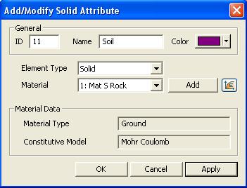


56 Attributes
57 Material Models Provided by GTS Structural Constitutive models. Non linear Elastic model for truss and emb edded truss Non linear elastic model for elastic links Geomembrane models Interface models Plate Interface model Non linear Pile model Geotechnical constitutive models Linear elastic models Transversely isotopic model Tresca model Von Mises model Mohr-Coulomb model Drucker Prager model Duncan-Chang Model Strain softening model Modified cam clay model Jointed rock model Hoek Brown model Modified Mohr Coulomb Jardine model D-min model Seepage constitutive model Permeabilty function Volumetric water contents function Linear Elastic constitutive model Non Linear Elastic constitutive model Elasto-plastic constitutive models Based on Couloumb s law Simulate the interface behaviour Pile and surrounding soils. Retaining wall and soil Lining and landfill Jointed rocks and fault zones. Model cohesionless soils and undrained behaviour of ground soil. Analysis of ductile materials. Simulating anchors, nails, steel made pipe pile etc. Model granular materials such as soil and concrete. Simulate gravel behaviour. Hyperbolic Controls the stress-strain softening of relationship. the soil. Simulate clay, mainly in consolidation analysis. Brittle Simulates failure the of behaviour rocks. of stratified and jointed rock Failure masses. of a jointed rock mass in response to induced stresses. Elastic Hardening and behaviour Plastic anisotropic of soil. behaviour.
58 Thank You! For more information, please visit us at Bridging Your Innovations to Realities GTS
Customized Pre/post-processor for DIANA. FX for DIANA
 Customized Pre/post-processor for DIANA FX for DIANA About FX4D for DIANA FX4D is a general purpose pre/post-processor for CAE simulation. FX4D has been specialized for civil/architectural applications.
3D Excavation by Tunnel Boring Machine
 3D Excavation by Tunnel Boring Machine Angel Francisco Martinez Application Engineer MIDAS NY Content 01 Introduction 02 Advantages of GTS NX for Tunneling 03 TBM Demo Introduction About MIDAS No. 1 in
Lateral Loading of Suction Pile in 3D
 Lateral Loading of Suction Pile in 3D Buoy Chain Sea Bed Suction Pile Integrated Solver Optimized for the next generation 64-bit platform Finite Element Solutions for Geotechnical Engineering 00 Overview
GTS NX INTERFACES AUTOCAD MIDAS GEN FOR TUNNEL SOIL PILE INTERACTION ANALYSIS
 INTERFACES AUTOCAD MIDAS GEN FOR TUNNEL SOIL PILE INTERACTION ANALYSIS Angel F. Martinez Civil Engineer MIDASOFT Integrated Solver Optimized for the next generation 64-bit platform Finite Element Solutions
MIDAS/FEA. Advanced Nonlinear and Detailed Analysis Program. MIDAS Information Technology Co., Ltd.
 MIDAS/FEA Advanced Nonlinear and Detailed Analysis Program Analysis Capabilities Static Analysis Construction Stage Analysis Moving Load Analysis Modal Analysis Linear Buckling Analysis Transient / Frequency
3D Soil Modelling (Geometry)
") 3D Soil Modelling (Geometry) Soil Profiling1 Description: This step shows how to import bolehole log data from a spreadsheet into GTS in preparation of soil modelling. Step 1. 1. Open GTS.exe 2. Main Menu:
3D Soil Modelling (Geometry) Soil Profiling1 Description: This step shows how to import bolehole log data from a spreadsheet into GTS in preparation of soil modelling. Step 1. 1. Open GTS.exe 2. Main Menu:
GTS. midas GTS Advanced Webinar. Date: June 5, 2012 Topic: General Use of midas GTS (Part II) Presenter: Vipul Kumar
 Presenter: Vipul Kumar") midas GTS Advanced Webinar Date: June 5, 2012 Topic: General Use of midas GTS (Part II) Presenter: Vipul Kumar Bridging Your Innovations to Realities GTS MIDAS Information Technology Co., Ltd. [1/30] Contents:
midas GTS Advanced Webinar Date: June 5, 2012 Topic: General Use of midas GTS (Part II) Presenter: Vipul Kumar Bridging Your Innovations to Realities GTS MIDAS Information Technology Co., Ltd. [1/30] Contents:
DIANA FINITE ELEMENT ANALYSIS
 DIANA FINITE ELEMENT ANALYSIS DIANA FEA a TNO Company DIANA F I N I T E E L E M E N T A N A LY S I S DIANA (DIsplacement ANAlyzer) is a multi-purpose finite element program, with a special strength in
DIANA. Finite Element Analysis. Civil Engineering Geotechnical Engineering Petroleum Engineering
 DIANA Finite Element Analysis Civil Engineering Geotechnical Engineering Petroleum Engineering NOW Advancing in new numerical analysis techniques Developing state-of-the-art solution for engineering applications
Slope Stability of Open Pit Mine in 2D & 3D
 Slope Stability of Open Pit Mine in D & D MIDASoft Inc. Angel Francisco Martinez Civil Engineer Email : a.martinez@midasit.com Integrated Solver Optimized for the next generation64-bit platform Finite
FOUNDATION IN OVERCONSOLIDATED CLAY
 1 FOUNDATION IN OVERCONSOLIDATED CLAY In this chapter a first application of PLAXIS 3D is considered, namely the settlement of a foundation in clay. This is the first step in becoming familiar with the
midas FEA V320 Table of Contents
 midas FEA V320 New Feature 01 CFD Moving Mesh Pre Process 01 File Open > File Preview 02 Extract Surface 03 Frame to Solid > Import 04 Tetra Auto mesh generation 05 Mesh options 06 Auto mesh Solid Function
Embedded Reinforcements
 Embedded Reinforcements Gerd-Jan Schreppers, January 2015 Abstract: This paper explains the concept and application of embedded reinforcements in DIANA. Basic assumptions and definitions, the pre-processing
Geometry Definition in the ADINA User Interface (AUI) Daniel Jose Payen, Ph.D. March 7, 2016
 Daniel Jose Payen, Ph.D. March 7, 2016") Geometry Definition in the ADINA User Interface (AUI) Daniel Jose Payen, Ph.D. March 7, 2016 ADINA R&D, Inc., 2016 1 Topics Presented ADINA에서쓰이는 Geometry 종류 Simple (AUI) geometry ADINA-M geometry ADINA-M
Geometry Definition in the ADINA User Interface (AUI) Daniel Jose Payen, Ph.D. March 7, 2016 ADINA R&D, Inc., 2016 1 Topics Presented ADINA에서쓰이는 Geometry 종류 Simple (AUI) geometry ADINA-M geometry ADINA-M
SETTLEMENT OF A CIRCULAR FOOTING ON SAND
 1 SETTLEMENT OF A CIRCULAR FOOTING ON SAND In this chapter a first application is considered, namely the settlement of a circular foundation footing on sand. This is the first step in becoming familiar
Solid Modeling: Part 1
 Solid Modeling: Part 1 Basics of Revolving, Extruding, and Boolean Operations Revolving Exercise: Stepped Shaft Start AutoCAD and use the solid.dwt template file to create a new drawing. Create the top
Advanced Nonlinear and Detail Analysis Program
 Overview Overview Geometry Modeling Mesh Generation Analysis Post-processing 2 Overview About FEA FEA is a state-of-the art integrated finite element analysis system for nonlinear and detail simulations
midas Civil Advanced Webinar Date: February 9th, 2012 Topic: General Use of midas Civil Presenter: Abhishek Das Bridging Your Innovations to Realities
 Advanced Webinar Date: February 9th, 2012 Topic: General Use of midas Civil Presenter: Abhishek Das Contents: Overview Modeling Boundary Conditions Loading Analysis Results Design and Misc. Introduction
Chapter 9 3D Modeling
 Chapter 9 3D Modeling Copyright The McGraw-Hill Companies, Inc. Permission required for reproduction or display. 3D Modeling Snapshot Since Mid 1980 s become common place in industry Software Types Wireframe
PLAXIS 3D. Tutorial Manual
 PLAXIS 3D Tutorial Manual 2010 Build 2681 TABLE OF CONTENTS TABLE OF CONTENTS 1 Introduction 5 2 Lesson 1: Foundation in overconsolidated clay 7 2.1 Geometry 7 2.2 Case A: Rigid foundation 8 2.3 Case B:
Diamond Engineer: Tunnel Series Training 2
 Diamond Engineer: Tunnel Series Training 2 Angel Francisco Martinez Application Engineer MIDAS NY Content 01 Introduction 02 Construction Stages 03 Demo 04 Post - Processing Introduction About MIDAS No.
PLAXIS 2D. Tutorial Manual
 PLAXIS 2D Tutorial Manual 2017 Build 8601 TABLE OF CONTENTS TABLE OF CONTENTS 1 Settlement of a circular footing on sand 7 1.1 Geometry 7 1.2 Case A: Rigid footing 8 1.3 Case B: Flexible footing 23 2 Submerged
AutoCAD for Engineers and Designers, 21st Edition. (3D and Advanced)
") AutoCAD 2015 for Engineers and Designers, 21st Edition (3D and Advanced) CADCIM Technologies 525 St. Andrews Drive Schererville, IN 46375, USA (www.cadcim.com) Contributing Author Sham Tickoo Professor
AutoCAD 2015 for Engineers and Designers, 21st Edition (3D and Advanced) CADCIM Technologies 525 St. Andrews Drive Schererville, IN 46375, USA (www.cadcim.com) Contributing Author Sham Tickoo Professor
NEi FEA. IRONCAD Advanced FEA. IRONCAD Advanced FEA. NEi FEA
 2011 Overview has been designed as a universal, adaptive and user-friendly graphical user interface for geometrical modeling, data input and visualization of results for all types of numerical simulation
3 SETTLEMENT OF A CIRCULAR FOOTING ON SAND (LESSON 1) Figure 3.1 Geometry of a circular footing on a sand layer
 Figure 3.1 Geometry of a circular footing on a sand layer") SETTLEMENT OF A CIRCULAR FOOTING ON SAND (LESSON 1) 3 SETTLEMENT OF A CIRCULAR FOOTING ON SAND (LESSON 1) In the previous chapter some general aspects and basic features of the PLAXIS program were presented.
SETTLEMENT OF A CIRCULAR FOOTING ON SAND (LESSON 1) 3 SETTLEMENT OF A CIRCULAR FOOTING ON SAND (LESSON 1) In the previous chapter some general aspects and basic features of the PLAXIS program were presented.
PLAXIS 3D. Tutorial Manual
 PLAXIS 3D Tutorial Manual 2017 Build 9039 TABLE OF CONTENTS TABLE OF CONTENTS 1 Foundation in overconsolidated clay 7 1.1 Case A: Rigid foundation 8 1.2 Case B: Raft foundation 20 1.3 Case C: Pile-Raft
Terrain settlement analysis
 Engineering manual No. 21 Updated: 02/2018 Terrain settlement analysis Program: File: FEM Demo_manual_21.gmk This example contains the solution to terrain settlement under surcharge loading using the Finite
Eurocodes and Innovation. Developments in Finite Element Analysis for Bridges
 Eurocodes and Innovation Developments in Finite Element Analysis for Bridges Developments in Finite Element Analysis for Bridges Ease of Use Vehicle Loading - Autocombinations Cable Tuning Construction
BobCAD CAM V25 4 Axis Standard Posted by Al /09/20 22:03
 BobCAD CAM V25 4 Axis Standard Posted by Al - 2012/09/20 22:03 Many BobCAD CAM clients that run a 4 axis have requested to work directly with Solids or STL files. In the past we only offered 4 axis indexing
Images from 3D Creative Magazine. 3D Modelling Systems
 Images from 3D Creative Magazine 3D Modelling Systems Contents Reference & Accuracy 3D Primitives Transforms Move (Translate) Rotate Scale Mirror Align 3D Booleans Deforms Bend Taper Skew Twist Squash
1 Classification of Shell Forms
 Proceedings of the 5 th International Conference on Computation of Shell and Spatial Structures June 1-4, 2005 Salzburg, Austria E. Ramm, W.A. Wall, K.-U. Bletzinger, M. Bischoff (eds.) www.iassiacm2005.de
Spring 2011 Workshop ESSENTIALS OF 3D MODELING IN RHINOCEROS February 10 th 2011 S.R. Crown Hall Lower Core Computer Lab
 [1] Open Rhinoceros. PART 1 INTRODUCTION [4] Click and hold on the Boundary Lines in where they form a crossing and Drag from TOP RIGHT to BOTTOM LEFT to enable only the PERSPECTIVE VIEW. [2] When the
Sequential Excavation for Mining in 2D and 3D
 Sequential Excavation for Mining in 2D and 3D MIDASoft Inc. Angel Francisco Martinez Civil Engineer Email : a.martinez@midasuser.com Integrated Solver Optimized for the next generation 64-bit platform
Convergent Modeling and Reverse Engineering
 Convergent Modeling and Reverse Engineering 25 October 2017 Realize innovation. Tod Parrella NX Design Product Management Product Engineering Solutions tod.parrella@siemens.com Realize innovation. Siemens
Chapter 20. Finite Element Method (FEM) Introduction
 Introduction") Chapter 20. Finite Element Method (FEM) Introduction The objective of this chapter is to explain basic terms of the particular field of problems and practical application of GEO 5 FEM program to solve
Chapter 20. Finite Element Method (FEM) Introduction The objective of this chapter is to explain basic terms of the particular field of problems and practical application of GEO 5 FEM program to solve
3D Modeling and Design Glossary - Beginner
 3D Modeling and Design Glossary - Beginner Align: to place or arrange (things) in a straight line. To use the Align tool, select at least two objects by Shift left-clicking on them or by dragging a box
Multiframe Windows Version 16. User Manual
 Multiframe Windows Version 16 User Manual Bentley Systems, Incorporated 2013 License & Copyright Multiframe Program & User Manual 2013 Bentley Systems, Incorporated iii Table of Contents License & Copyright...
2D & 3D Semi Coupled Analysis Seepage-Stress-Slope
 D & D Semi Coupled Analysis Seepage-Stress-Slope MIDASoft Inc. Angel Francisco Martinez Civil Engineer MIDASoft NY office Integrated Solver Optimized for the next generation 6-bit platform Finite Element
New Constitutive Material Models in RS 2
 New Constitutive Material Models in RS 2 1.0 The Softening-Hardening Material Model Experimental evidence indicates that plastic deformation in soils starts from the early stages of loading. The typical
Modelling of Tunnels in 2D & 3D
 MIDAS Geotechnical Know-how Sharing Series November 28 th, 2017 (Tue) 10:00 ~ 11:00 AM (CET) Session 3. Modelling of Tunnels in 2D & 3D JaeSeok Yang Principal Geotechnical Engineer, MIDAS IT Integrated
SolidWorks 2013 Part II - Advanced Techniques
 SolidWorks 2013 Part II - Advanced Techniques Parts, Surfaces, Sheet Metal, SimulationXpress, Top-Down Assemblies, Core and Cavity Molds Paul Tran CSWE, CSWI Supplemental Files SDC PUBLICATIONS Schroff
Create Complex Surfaces
 Create Complex Surfaces In this lesson, you will be introduced to the functionalities available in the Generative Surface Design workbench. Lesson content: Case Study: Surface Design Design Intent Stages
Introduction to ANSYS DesignModeler
 Lecture 5 Modeling 14. 5 Release Introduction to ANSYS DesignModeler 2012 ANSYS, Inc. November 20, 2012 1 Release 14.5 Preprocessing Workflow Geometry Creation OR Geometry Import Geometry Operations Meshing
TABLE OF CONTENTS WHAT IS ADVANCE DESIGN? INSTALLING ADVANCE DESIGN... 8 System requirements... 8 Advance Design installation...
 Starting Guide 2019 TABLE OF CONTENTS INTRODUCTION... 5 Welcome to Advance Design... 5 About this guide... 6 Where to find information?... 6 Contacting technical support... 6 WHAT IS ADVANCE DESIGN?...
Technical Education Services
 Autodesk Fusion 360: Introduction to Parametric Modeling Course Length: 3 days Official Training Guide The Autodesk Fusion 360 Introduction to Parametric Modeling training course provides you with an understanding
Autodesk 123D Beta5 Overview
 Autodesk 123D Beta5 Overview Welcome. This overview document for Autodesk 123D will assist you in developing your understanding of the software and how you can use it to create your design ideas. Designing
Freeform / Freeform PLUS
 Freeform / Freeform PLUS WORKING WITH FREEFORM Work from Coarse Clay to Fine When creating new models from scratch, it is best to first create a rough shape using a coarse clay setting such as Rough Shape
3. Preprocessing of ABAQUS/CAE
 3.1 Create new model database 3. Preprocessing of ABAQUS/CAE A finite element analysis in ABAQUS/CAE starts from create new model database in the toolbar. Then save it with a name user defined. To build
Computer Aided Engineering Applications
 Computer Aided Engineering Applications 1A.Geometric Modeling 1.1 Geometric modelling methods 1.2 Data representation 1.3 Modeling functions 1.4 Structure of a CAD system Engi 6928 - Fall 2014 1.Geometric
Additional Surface Tools
 Additional Surface Tools Several additional surface tools, techniques, and related functions are available. This supplement provides a brief introduction to those functions. Panel Part Features Replace
PHASED EXCAVATION OF A SHIELD TUNNEL
 5 PHASED EXCAVATION OF A SHIELD TUNNEL The lining of a shield tunnel is often constructed using prefabricated concrete ring segments, which are bolted together within the tunnel boring machine to form
SUBMERGED CONSTRUCTION OF AN EXCAVATION
 2 SUBMERGED CONSTRUCTION OF AN EXCAVATION This tutorial illustrates the use of PLAXIS for the analysis of submerged construction of an excavation. Most of the program features that were used in Tutorial
Modeling Technology Group
 Modeling Technology Group Hiroshi Hayashi David Ogirala Matt Nedrich Jeff Ridenbaugh Spencer Smith Saba Bokhari John Gray Charles Hellstrom Bryan Linthicum Polygon Models (part-1) What are polygons? -
3D Design with 123D Design
 3D Design with 123D Design Introduction: 3D Design involves thinking and creating in 3 dimensions. x, y and z axis Working with 123D Design 123D Design is a 3D design software package from Autodesk. A
Introduction: RS 3 Tutorial 1 Quick Start
 Introduction: RS 3 Tutorial 1 Quick Start Welcome to RS 3. This tutorial introduces some basic features of RS 3. The model analyzes the effect of tank loading on an existing sloped underground tunnel.
Topology Optimization for Designers
 TM Topology Optimization for Designers Siemens AG 2016 Realize innovation. Topology Optimization for Designers Product Features Uses a different approach than traditional Topology Optimization solutions.
SolidWorks 2013 and Engineering Graphics
 SolidWorks 2013 and Engineering Graphics An Integrated Approach Randy H. Shih SDC PUBLICATIONS Schroff Development Corporation Better Textbooks. Lower Prices. www.sdcpublications.com Visit the following
SOLIDWORKS 2016 and Engineering Graphics
 SOLIDWORKS 2016 and Engineering Graphics An Integrated Approach Randy H. Shih SDC PUBLICATIONS Better Textbooks. Lower Prices. www.sdcpublications.com Powered by TCPDF (www.tcpdf.org) Visit the following
USER INTERFACE MANUAL
 SAP2000 Integrated Finite Elements Analysis and Design of Structures GRAPHIC USER INTERFACE MANUAL Computers and Structures, Inc. Berkeley, California, USA Version 7.0 August 1998 COPYRIGHT The computer
2: Static analysis of a plate
 2: Static analysis of a plate Topics covered Project description Using SolidWorks Simulation interface Linear static analysis with solid elements Finding reaction forces Controlling discretization errors
Exercise Guide. Published: August MecSoft Corpotation
 VisualCAD Exercise Guide Published: August 2018 MecSoft Corpotation Copyright 1998-2018 VisualCAD 2018 Exercise Guide by Mecsoft Corporation User Notes: Contents 2 Table of Contents About this Guide 4
SolidWorks 2014 Part II - Advanced Techniques
 SolidWorks 2014 Part II - Advanced Techniques Parts, Surfaces, Sheet Metal, SimulationXpress, Top-Down Assemblies, Core and Cavity Molds Paul Tran CSWE, CSWI SDC PUBLICATIONS Better Textbooks. Lower Prices.
SAMCEF for ROTORS. Chapter 3.2: Rotor modeling. This document is the property of SAMTECH S.A. MEF A, Page 1
 SAMCEF for ROTORS Chapter 3.2: Rotor modeling This document is the property of SAMTECH S.A. MEF 101-03-2-A, Page 1 Table of contents Introduction Introduction 1D Model 2D Model 3D Model 1D Models: Beam-Spring-
L1 - Introduction. Contents. Introduction of CAD/CAM system Components of CAD/CAM systems Basic concepts of graphics programming
 L1 - Introduction Contents Introduction of CAD/CAM system Components of CAD/CAM systems Basic concepts of graphics programming 1 Definitions Computer-Aided Design (CAD) The technology concerned with the
DRY EXCAVATION USING A TIE BACK WALL
 3 This example involves the dry construction of an excavation. The excavation is supported by concrete diaphragm walls. The walls are tied back by prestressed ground anchors. Silt Sand 10 m 2 m 20 m 10
CATIA Surface Design
 CATIA V5 Training Exercises CATIA Surface Design Version 5 Release 19 September 2008 EDU_CAT_EN_GS1_FX_V5R19 Table of Contents (1/2) Creating Wireframe Geometry: Recap Exercises 4 Creating Wireframe Geometry:
SOLIDWORKS 2019 Advanced Techniques
 SOLIDWORKS 2019 Advanced Techniques Mastering Parts, Surfaces, Sheet Metal, SimulationXpress, Top Down Assemblies, Core & Cavity Molds Paul Tran CSWE, CSWI SDC PUBLICATIONS Better Textbooks. Lower Prices.
Lesson 4: Surface Re-limitation and Connection
 Lesson 4: Surface Re-limitation and Connection In this lesson you will learn how to limit the surfaces and form connection between the surfaces. Lesson contents: Case Study: Surface Re-limitation and Connection
Lecture 4, 5/27/2017, Rhino Interface an overview
 數字建築與城市设计 Spring 2017 Lecture 4, 5/27/2017, Rhino Interface an overview Copyright 2017, Chiu-Shui Chan. All Rights Reserved. This lecture concentrates on the use of tools, 3D solid modeling and editing
Modeling a Scanned Object with RapidWorks
 Modeling a Scanned Object with RapidWorks RapidWorks allows you to use a scanned point cloud of an object from the NextEngine Desktop 3D Scanner to create a CAD representation of an object. This guide
Slope Stability Problem Session
 Slope Stability Problem Session Stability Analysis of a Proposed Soil Slope Using Slide 5.0 Tuesday, February 28, 2006 10:00 am - 12:00 pm GeoCongress 2006 Atlanta, GA software tools for rock and soil
SolidWorks. An Overview of SolidWorks and Its Associated Analysis Programs
 An Overview of SolidWorks and Its Associated Analysis Programs prepared by Prof. D. Xue University of Calgary SolidWorks - a solid modeling CAD tool. COSMOSWorks - a design analysis system fully integrated
Examine 2D 8.0 is here!
 Examine 2D 8.0 is here! Rocscience is pleased to announce the release of Examine 2D version 8.0, an upgrade to our very popular FREE stress analysis program. Examine 2D uses the boundary element method
Feature-Based Modeling and Optional Advanced Modeling. ENGR 1182 SolidWorks 05
 Feature-Based Modeling and Optional Advanced Modeling ENGR 1182 SolidWorks 05 Today s Objectives Feature-Based Modeling (comprised of 2 sections as shown below) 1. Breaking it down into features Creating
FEA Applications I MET 415 Review Course Structure: 15 week course Weekly Schedule 50 minute lecture 2.5 hour laboratory 50 minute lecture
 FEA Applications I MET 415 Review Course Structure: 15 week course Weekly Schedule 50 minute lecture 2.5 hour laboratory 50 minute lecture Goal: Obtain feedback from Industry Users on course presentation
Education Curriculum Surface Design Specialist
 Education Curriculum Surface Design Specialist Invest your time in imagining next generation designs. Here s what we will teach you to give shape to your imagination. CATIA Surface Design Specialist CATIA
ARCHITECTURE & GAMES. A is for Architect Simple Mass Modeling FORM & SPACE. Industry Careers Framework. Applied. Getting Started.
 A is for Architect Simple Mass Modeling One of the first introductions to form and space usually comes at a very early age. As an infant, you might have played with building blocks to help hone your motor
Engineering Effects of Boundary Conditions (Fixtures and Temperatures) J.E. Akin, Rice University, Mechanical Engineering
 J.E. Akin, Rice University, Mechanical Engineering") Engineering Effects of Boundary Conditions (Fixtures and Temperatures) J.E. Akin, Rice University, Mechanical Engineering Here SolidWorks stress simulation tutorials will be re-visited to show how they
Engineering Effects of Boundary Conditions (Fixtures and Temperatures) J.E. Akin, Rice University, Mechanical Engineering Here SolidWorks stress simulation tutorials will be re-visited to show how they
Solidworks 2006 Surface-modeling
 Solidworks 2006 Surface-modeling (Tutorial 2-Mouse) Surface-modeling Solid-modeling A- 1 Assembly Design Design with a Master Model Surface-modeling Tutorial 2A Import 2D outline drawing into Solidworks2006
2016(v1.1) Release Notes
 Release Notes") 2016(v1.1) Release Notes Ver 4.0.0. 개정내용 2016(v1.1) Release Notes Copyright c 1989~2014. MIDAS Information Technology Co., Ltd. ALL RIGHTS RESERVED. 1 / 21 Release Note 2016(v1.1) Release Notes Pre-Processing
2016(v1.1) Release Notes Ver 4.0.0. 개정내용 2016(v1.1) Release Notes Copyright c 1989~2014. MIDAS Information Technology Co., Ltd. ALL RIGHTS RESERVED. 1 / 21 Release Note 2016(v1.1) Release Notes Pre-Processing
General modeling guidelines
 General modeling guidelines Some quotes from industry FEA experts: Finite element analysis is a very powerful tool with which to design products of superior quality. Like all tools, it can be used properly,
New developments in numerical modelling of pile installation
 New developments in numerical modelling of pile installation Nguyen Phuong, Frits van Tol, Alexander Rohe 18 September 2014 KIVI Geotechnical Lectures Evening TU Delft Displacement piles à installation
Introduction to ANSYS FLUENT Meshing
 Workshop 02 Volume Fill Methods Introduction to ANSYS FLUENT Meshing 1 2011 ANSYS, Inc. December 21, 2012 I Introduction Workshop Description: Mesh files will be read into the Fluent Meshing software ready
SDC. Engineering Analysis with COSMOSWorks. Paul M. Kurowski Ph.D., P.Eng. SolidWorks 2003 / COSMOSWorks 2003
 Engineering Analysis with COSMOSWorks SolidWorks 2003 / COSMOSWorks 2003 Paul M. Kurowski Ph.D., P.Eng. SDC PUBLICATIONS Design Generator, Inc. Schroff Development Corporation www.schroff.com www.schroff-europe.com
Geometric Modeling Topics
 Geometric Modeling Topics George Allen, george.allen@siemens.com Outline General background Convergent modeling Multi-material objects Giga-face lattices Page 2 Boundary Representation (b-rep) Topology
Engineering Drawing II
 Instructional Unit Basic Shading and Rendering -Basic Shading -Students will be able -Demonstrate the ability Class Discussions 3.1.12.B, -Basic Rendering to shade a 3D model to apply shading to a 3D 3.2.12.C,
Lesson 3: Surface Creation
 Lesson 3: Surface Creation In this lesson, you will learn how to create surfaces from wireframes. Lesson Contents: Case Study: Surface Creation Design Intent Stages in the Process Choice of Surface Sweeping
Engineeringmanuals. Part3
 Engineeringmanuals Part3 Engineering manuals for GEO5 programs Part 3 Chapter 1-12, refer to Engineering Manual Part 1 Chapter 13-19, refer to Engineering Manual Part 2 Chapter 20. Finite Element Method
PLAXIS 3D Tunnel. Tutorial Manual
 PLAXIS 3D Tunnel Tutorial Manual TABLE OF CONTENTS TABLE OF CONTENTS 1 Introduction...1-1 2 Getting started...2-1 2.1 Installation...2-1 2.2 General modelling aspects...2-1 2.3 Input procedures...2-3
ANSYS Element. elearning. Peter Barrett October CAE Associates Inc. and ANSYS Inc. All rights reserved.
 ANSYS Element Selection elearning Peter Barrett October 2012 2012 CAE Associates Inc. and ANSYS Inc. All rights reserved. ANSYS Element Selection What is the best element type(s) for my analysis? Best
Modeling Foundations in RS
 Modeling Foundations in RS 3 Piled Raft Modeling in RS 3 Deep foundation piles are commonly used to increase foundation stability and to increase the bearing capacity of structural systems. The design
user manual vol. 2: modeling
 user manual vol. 2: modeling An Company solidthinking Release 8.0 User Manual Modeling - Volume 2 1993-2009 solidthinking Inc. Part N. 80-25041-10301 Copyright 1993-2009 solidthinking, Inc. All rights
Geometric Modeling Systems
 Geometric Modeling Systems Wireframe Modeling use lines/curves and points for 2D or 3D largely replaced by surface and solid models Surface Modeling wireframe information plus surface definitions supports
ATENA Program Documentation Part 4-2. Tutorial for Program ATENA 3D. Written by: Jan Červenka, Zdenka Procházková, Tereza Sajdlová
 Červenka Consulting s.ro. Na Hrebenkach 55 150 00 Prague Czech Republic Phone: +420 220 610 018 E-mail: cervenka@cervenka.cz Web: http://www.cervenka.cz ATENA Program Documentation Part 4-2 Tutorial for
AutoCAD 2013 Tutorial - Second Level: 3D Modeling
 AutoCAD 2013 Tutorial - Second Level: 3D Modeling Randy H. Shih SDC PUBLICATIONS Schroff Development Corporation Better Textbooks. Lower Prices. www.sdcpublications.com Visit the following websites to
CE Advanced Structural Analysis. Lab 4 SAP2000 Plane Elasticity
 Department of Civil & Geological Engineering COLLEGE OF ENGINEERING CE 463.3 Advanced Structural Analysis Lab 4 SAP2000 Plane Elasticity February 27 th, 2013 T.A: Ouafi Saha Professor: M. Boulfiza 1. Rectangular
An Overview of Computer Aided Design and Finite Element Analysis
 An Overview of Computer Aided Design and Finite Element Analysis by James Doane, PhD, PE Contents 1.0 Course Overview... 4 2.0 General Concepts... 4 2.1 What is Computer Aided Design... 4 2.1.1 2D verses
3DEC 3DEC ITASCA ITASCA VERSION 5.0 VERSION 5.0
 ITASCA Consulting Group, Inc. An Itasca International Company 3DEC VERSION 5.0 Advanced, Three Dimensional Discrete Element Modeling for Geotechnical Analysis of Rock, Blocky Structures and Structural
Introduction to Solid Modeling Parametric Modeling. Mechanical Engineering Dept.
 Introduction to Solid Modeling Parametric Modeling 1 Why draw 3D Models? 3D models are easier to interpret. Simulation under real-life conditions. Less expensive than building a physical model. 3D models
In-plane principal stress output in DIANA
 analys: linear static. class: large. constr: suppor. elemen: hx24l solid tp18l. load: edge elemen force node. materi: elasti isotro. option: direct. result: cauchy displa princi stress total. In-plane