Tutorial on Verilog HDL
|
|
|
- Peter Strickland
- 6 years ago
- Views:
Transcription
1 Tutorial on Verilog HDL
2 HDL Hardware Description Languages Widely used in logic design Verilog and VHDL Describe hardware using code Document logic functions Simulate logic before building Synthesize code into gates and layout Requires a library of standard cells
3 Verilog Verilog is one of the two major Hardware Description Languages(HDL) used by hardware designers in industry and academia. VHDL is another one Verilog is easier to learn and use than VHDL Verilog HDL allows a hardware designer to describe designs at a high level of abstraction such as at the architectural or behavioral level as well as the lower implementation levels (i.e., gate and switch levels).
4 Why use Verilog HDL Digital systems are highly complex. The Verilog language provides digital designer a software platform. Verilog allows users to express their design with behavioral constructs. A program tool can convert the Verilog program to a description that was used to make chip, like VLSI.
5 Taste of Verilog Module name Module ports module Add_half ( sum, c_out, a, b ); input a, b; output sum, c_out; wire c_out_bar; xor (sum, a, b); // xor G1(sum, a, b); nand (c_out_bar, a, b); not (c_out, c_out_bar); endmodule Declaration of port modes Declaration of internal signal Instantiation of primitive gates a b G1 c_out_bar sum Verilog keywords c_out
6 Lexical Convention Lexical convention are close to C++. Comment // to the end of the line. /* to */ across several lines. Keywords are lower case letter. the language is case sensitive
7 Lexical Convention Numbers are specified in the traditional form or below. <size><base format><number> Size: contains decimal digitals that specify the size of the constant in the number of bits. Base format: is the single character followed by one of the following characters b(binary),d(decimal),o(octal),h(hex). Number: legal digital.
8 Lexical Convention Example : 347 // decimal number 4 b101 // 4- bit binary number o12 // 8-bit octal number h8f // 10-bit hex number 8f 8 d83 // 8-bit decimal number 83 String in double quotes this is a introduction
9 Lexical Convention Operator are one, two, or three characters and are used in the expressions. just like C++. Identifier: specified by a letter or underscore followed by more letter or digits, or signs.
10 Program structure Structure module <module name> (< port list>); < declares> <module items> endmodule. Module name an identifier that uniquely names the module.. Port list a list of input, inout and output ports which are referenced in other modules.
11 Program structure. Declares section specifies data objects as registers, memories and wires as well as procedural constructs such as functions and tasks.. Module items initial constructs always constructs assignment.
12 Test Module structure module <test module name> ; // Data type declaration. Inputs declared as reg and outputs declared as wire // Instantiate module ( call the module that is going to be tested) // Apply the stimulus // Display results // Display results endmodule
13 Three Modeling Styles in Verilog Structural modeling (Gate-Level Modeling) Use predefined or user-defined primitive gates. Dataflow modeling Use assignment statements (assign) Behavioral modeling Use procedural assignment statements (always)
14 Structural model //structural model of a NAND gate // program nand2.v module my_nand(a, B, F); input A, B; output F; nand G(F, A, B); // first parameter must be output. endmodule
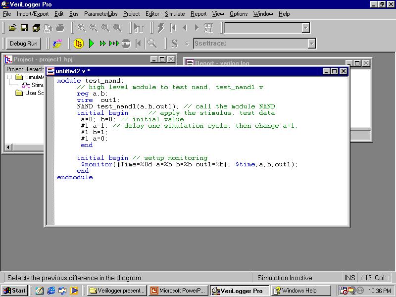
15 Example of gate NAND Test bench module test_nand for the nand1.v module test_my_nand; // Test bench to test nand reg A, B; wire F; my_nand test_my_nand(a, B, F); // instantiate my_nand. initial begin // apply the stimulus, test data A = 1'b0; B = 1'b0; #100 A = 1'b1; // delay one simulation cycle, then change A=>1. #100 B = 1'b1; #100 A = 1'b0; end initial #500 $finish; begin // setup monitoring //$monitor("time=%0d a=%b b=%b out1=%b", $time, A, B, F); //#500 $finish; end endmodule
16 Structural Modeling //Gate-level description of a 2-to-4-line decoder //Figure 4-19 module decoder_gl (input A,B,E, output [0:3] D); wire Anot, Bnot, Enot; not n1 (Anot, A), n2 (Bnot, B), n3 (Enot, E); nand n4 (D[0], Anot, Bnot, Enot), n5 (D[1], Anot,B, Enot), n6 (D[2], A, Bnot, Enot), n7 (D[3], A, B, Enot); endmodule
17 //Gate-level hierarchical description of 4-bit adder // Description of half adder (see Fig 4-5b) //module halfadder (S,C,x,y); // input x,y; // output S,C; module halfadder (output S,C, input x,y); //Instantiate primitive gates xor (S,x,y); and (C,x,y); endmodule //Description of full adder (see Fig 4-8) module fulladder (output S,C, input x,y,z); wire S1,C1,C2; //Outputs of first XOR and two AND gates halfadder HA1 (S1,C1,x,y), HA2 (S,C2,S1,z); //Instantiate the halfadder or g1(c,c2,c1); endmodule
18 //Description of 4-bit adder (see Fig 4-9) module ripple_carry_4bit_adder (output [3:0] S, output C4, input [3:0] A,B, input C0) // input [3:0] A,B; //input C0; //output [3:0] S; //output C4; wire C1,C2,C3; //Intermediate carries //Instantiate the fulladder fulladder FA0 (S[0], C1, A[0], B[0], C0), FA1 (S[1], C2, A[1], B[1], C1), FA2 (S[2], C3, A[2], B[2], C2), FA3 (S[3], C4, A[3], B[3], C3); endmodule The names are required!
19 Dataflow Modeling //HDL Example 4-3 // //Dataflow description of a 2-to-4-line decoder //See Fig.4-19 module decoder_df (output [0:3] D, input A, B, enable); assign D[0] = ~(~A & ~B & ~ enable), endmodule D[1] = ~(~A & B & ~ enable), D[2] = ~(A & ~B & ~ enable), D[3] = ~(A & B & ~ enable);
20 Dataflow Modeling //HDL Example 4-4 // //Dataflow description of 4-bit adder module binary_adder (A, B, Cin, SUM, Cout); input [3:0] A,B; input Cin; output [3:0] SUM; output Cout; assign {Cout, SUM} = A + B + Cin; endmodule concatenation Binary addition
21 Dataflow Modeling //HDL Example 4-5 // //Dataflow description of a 4-bit comparator. module magcomp (A,B,ALTB,AGTB,AEQB); input [3:0] A,B; output ALTB,AGTB,AEQB; assign ALTB = (A < B), AGTB = (A > B), AEQB = (A == B); endmodule
22 Dataflow Modeling //HDL Example 4-6 // //Dataflow description of 2-to-1-line multiplexer module mux2x1_df (A, B, select, OUT); input A,B,select; output OUT; assign OUT = select? A : B; endmodule
23 Behavioral Description module Add_half ( sum, c_out, a, b ); input a, b; a output sum, c_out; reg sum, c_out; b ( a or b ) begin sum = a ^ b; // Exclusive or c_out = a & b; // And end endmodule Must be of the reg type Procedure assignment statements Add_half sum c_out Event control expression
24 Example of Flip-flop module Flip_flop ( q, data_in, clk, rst ); input data_in, clk, rst; output q; reg q; ( posedge clk ) begin if ( rst == 1) q = 0; else q = data_in; end endmodule data_in clk rst Declaration of synchronous behavior Procedural statement q
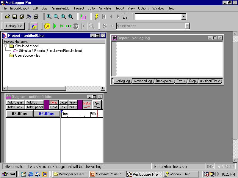
25 Using Verilogger Pro Evaluation Version. enter the window of Verilogger Start Program SynaptiCad Verilogger Pro..
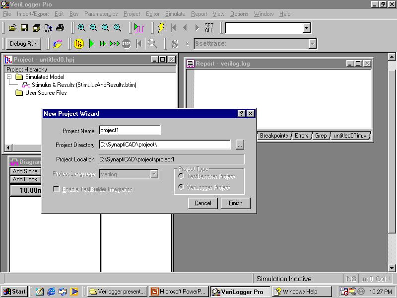
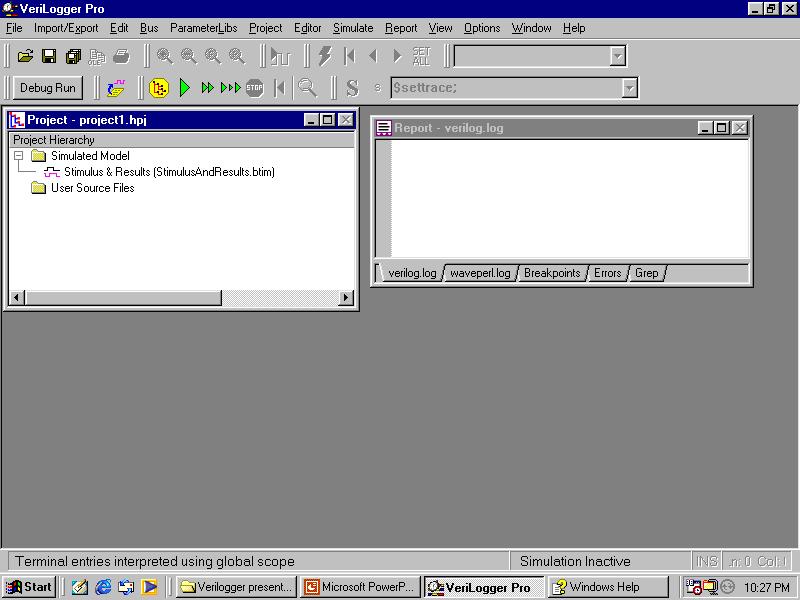
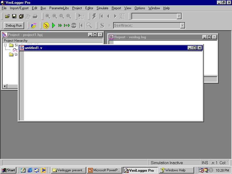
26 How to build a new project Click Menu [ Project] [New Project] enter the conversation window. Enter the Project Name. default: untitled.hpj. *.hpj Enter the Project Directory C:\SynaptiCAD\project\ Or others..click the [Finish] to close the window.
27 Other menus of [Project] [Open Project] [Close Project] [Save Project] [Save Project as] [Add User Source Files] all the user source used by this project. Project setting Print Project Hierarchy
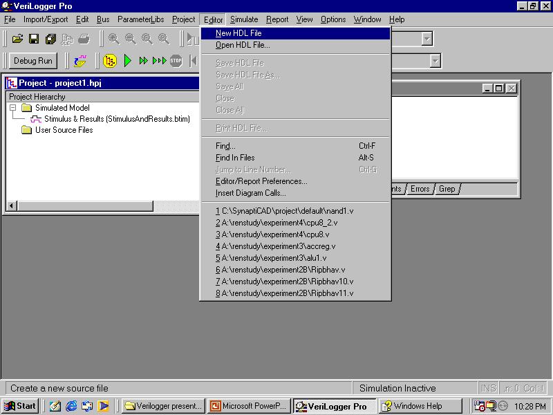
28 Verilogger Editor Use the Verilogger Editor to build a program. In the Verilogger Window: click [Editor] [New HDL file] pop up a editor window for you.. Others Menu in the [Editor] same as Menu[Project]
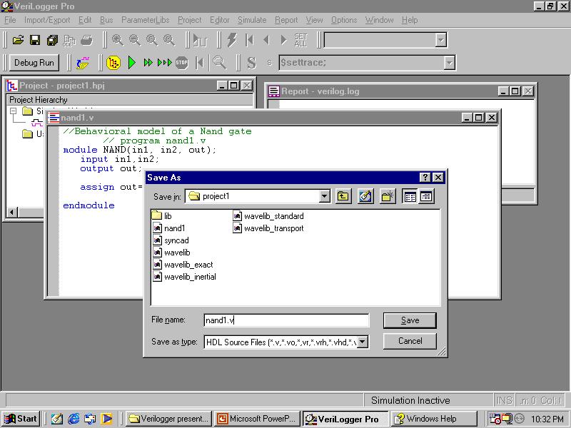
29 Example of gate NAND Save the HDL files as nand1.v in menu [Editor] [Save HDL File As] and save another HDL file as test-nand1.v Attach these two HDL files to the new project test.hpj in [project]->[add User Source Files] Run the simulation program run/resume simulation button or in the [simulate].
30 How to build a new project?
31

32
33
34
35 How to create a HDL file?
36
37
38
39 How to save the HDL file?
40
41
42
43
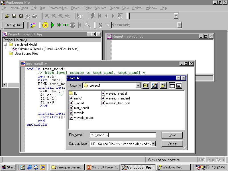
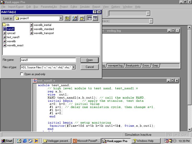
44 How to add a source HDL file to a Project(project1)
45
46
47
48

49
50 Now, Ready to run the program!
51
52
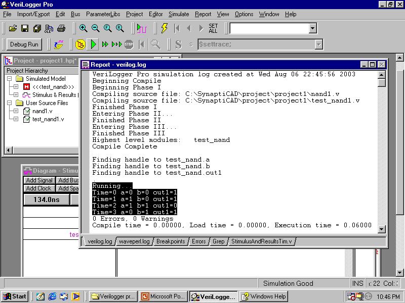
53 The Report Window of Verilogger.(all the simulation information is in this window)
54
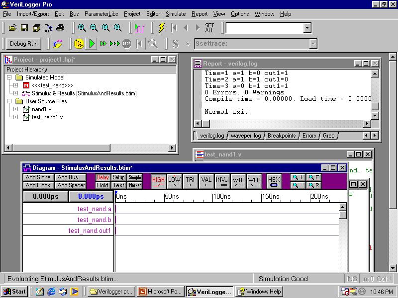
55 Example of gate NAND Simulation report from Verilog-Report window. Running... Time=0 a=0 b=0 out1=1 Time=1 a=1 b=0 out1=1 Time=2 a=1 b=1 out1=0 Time=3 a=0 b=1 out1=1 0 Errors, 0 Warnings Compile time = , Load time = , Execution time = Normal exit
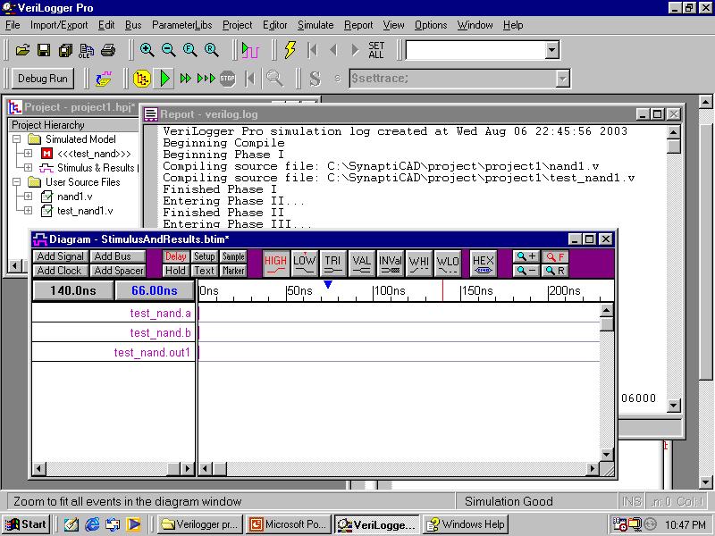
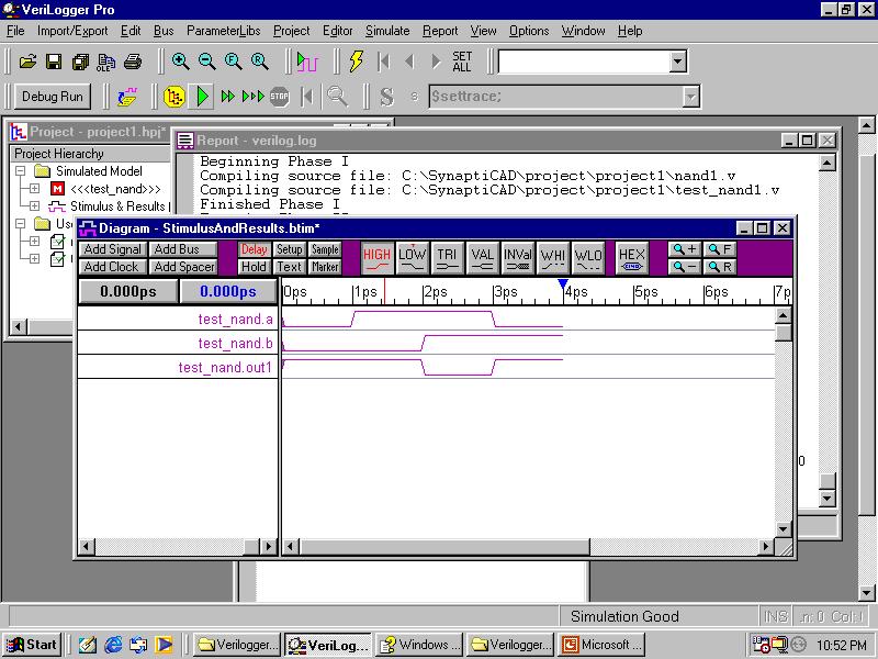
56 Diagram window of Simulation result
57
58

59
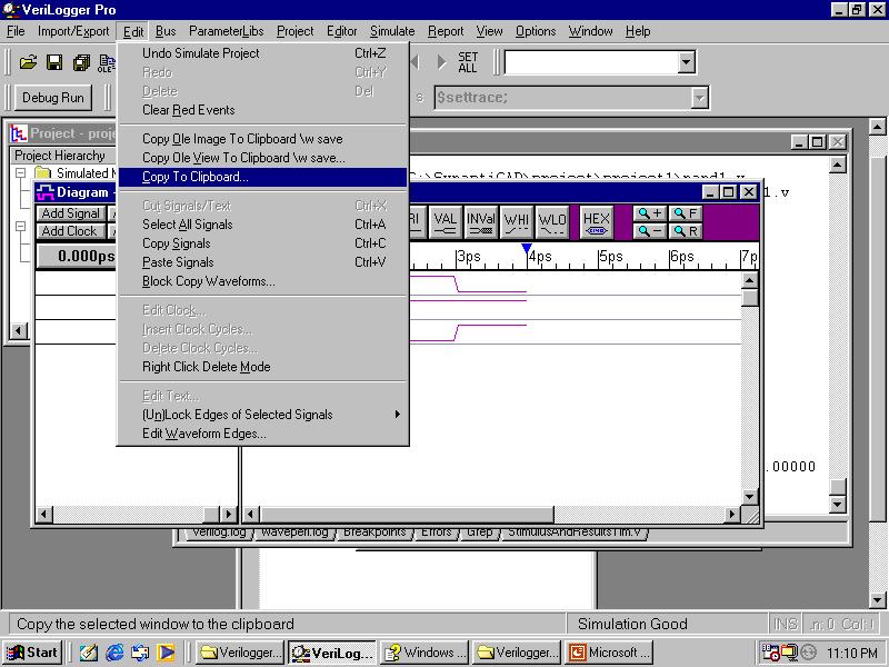
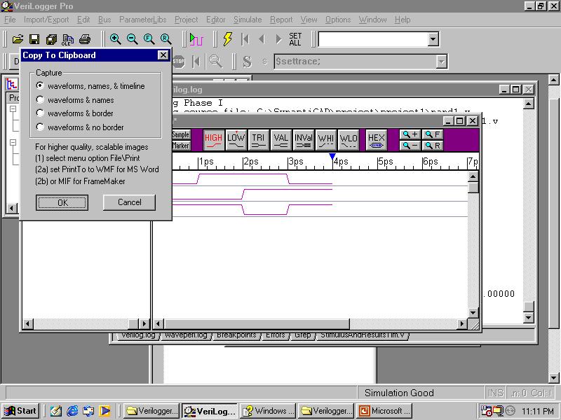
60 How to copy the diagram to Microsoft Word!
61 Example of gate NAND Wave from Verilog diagram. Verilog windows Activate the the diagram windows Method 1: [File] -> [Print Diagram] -> Print to: [WMF Metafile[MS Word]; Method 2: [edit] [copy to clipboard] select wave form, name and time line select ok then you can paste the diagram to anywhere you want.
62
63
64
65 You can paste the diagram here!
Design Using Verilog
 EGC220 Design Using Verilog Baback Izadi Division of Engineering Programs bai@engr.newpaltz.edu Basic Verilog Lexical Convention Lexical convention are close to C++. Comment // to the of the line. /* to
HDL for Combinational Circuits. ENEL211 Digital Technology
 HDL for Combinational Circuits ENEL211 Digital Technology Lecture Outline Vectors Modular design Tri-state gates Dataflow modelling Behavioural Modelling Vectors Often we want multi-bit quantities in digital
What is Verilog HDL? Lecture 1: Verilog HDL Introduction. Basic Design Methodology. What is VHDL? Requirements
 What is Verilog HDL? Lecture 1: Verilog HDL Introduction Verilog Hardware Description Language(HDL)? A high-level computer language can model, represent and simulate digital design Hardware concurrency
Advanced Digital Design Using FPGA. Dr. Shahrokh Abadi
 Advanced Digital Design Using FPGA Dr. Shahrokh Abadi 1 Venue Computer Lab: Tuesdays 10 12 am (Fixed) Computer Lab: Wednesday 10-12 am (Every other odd weeks) Note: Due to some unpredicted problems with
Introduction to Verilog HDL. Verilog 1
 Introduction to HDL Hardware Description Language (HDL) High-Level Programming Language Special constructs to model microelectronic circuits Describe the operation of a circuit at various levels of abstraction
Verilog Tutorial (Structure, Test)
") Digital Circuit Design and Language Verilog Tutorial (Structure, Test) Chang, Ik Joon Kyunghee University Hierarchical Design Top-down Design Methodology Bottom-up Design Methodology Module START Example)
Digital Circuit Design and Language Verilog Tutorial (Structure, Test) Chang, Ik Joon Kyunghee University Hierarchical Design Top-down Design Methodology Bottom-up Design Methodology Module START Example)
FPGA Design Challenge :Techkriti 14 Digital Design using Verilog Part 1
 FPGA Design Challenge :Techkriti 14 Digital Design using Verilog Part 1 Anurag Dwivedi Digital Design : Bottom Up Approach Basic Block - Gates Digital Design : Bottom Up Approach Gates -> Flip Flops Digital
ECEN 468 Advanced Digital System Design
 ECEN 468 Advanced Digital System Design Lecture 19: Logic Design with Verilog Verilog Module v Description of internal structure/function o Implicit semantic of time associated with each data object/ signal
Federal Urdu University of Arts, Science and Technology, Islamabad VLSI SYSTEM DESIGN. Prepared By: Engr. Yousaf Hameed.
 VLSI SYSTEM DESIGN Prepared By: Engr. Yousaf Hameed Lab Engineer BASIC ELECTRICAL & DIGITAL SYSTEMS LAB DEPARTMENT OF ELECTRICAL ENGINEERING VLSI System Design 1 LAB 01 Schematic Introduction to DSCH and
EE 8351 Digital Logic Circuits Ms.J.Jayaudhaya, ASP/EEE
 EE 8351 Digital Logic Circuits Ms.J.Jayaudhaya, ASP/EEE 1 Logic circuits for digital systems may be combinational or sequential. A combinational circuit consists of input variables, logic gates, and output
DIGITAL SYSTEM DESIGN
 DIGITAL SYSTEM DESIGN Prepared By: Engr. Yousaf Hameed Lab Engineer BASIC ELECTRICAL & DIGITAL SYSTEMS LAB DEPARTMENT OF ELECTRICAL ENGINEERING Digital System Design 1 Name: Registration No: Roll No: Semester:
P-1/26. Samir Palnitkar. Prentice-Hall, Inc. INSTRUCTOR : CHING-LUNG SU.
 : P-1/26 Textbook: Verilog HDL 2 nd. Edition Samir Palnitkar Prentice-Hall, Inc. : INSTRUCTOR : CHING-LUNG SU E-mail: kevinsu@yuntech.edu.tw Chapter 4 P-2/26 Chapter 4 Modules and Outline of Chapter 4
Introduction. Why Use HDL? Simulation output. Explanation
 Introduction Verilog HDL is a Hardware Description Language (HDL) HDL is a language used to describe a digital system, for example, a computer or a component of a computer. Most popular HDLs are VHDL and
Digital Design with FPGAs. By Neeraj Kulkarni
 Digital Design with FPGAs By Neeraj Kulkarni Some Basic Electronics Basic Elements: Gates: And, Or, Nor, Nand, Xor.. Memory elements: Flip Flops, Registers.. Techniques to design a circuit using basic
Verilog. What is Verilog? VHDL vs. Verilog. Hardware description language: Two major languages. Many EDA tools support HDL-based design
 Verilog What is Verilog? Hardware description language: Are used to describe digital system in text form Used for modeling, simulation, design Two major languages Verilog (IEEE 1364), latest version is
Hardware Description Languages (HDLs) Verilog
 Verilog") Hardware Description Languages (HDLs) Verilog Material from Mano & Ciletti book By Kurtulus KULLU Ankara University What are HDLs? A Hardware Description Language resembles a programming language specifically
Hardware Description Languages (HDLs) Verilog Material from Mano & Ciletti book By Kurtulus KULLU Ankara University What are HDLs? A Hardware Description Language resembles a programming language specifically
Module 2.1 Gate-Level/Structural Modeling. UNIT 2: Modeling in Verilog
 Module 2.1 Gate-Level/Structural Modeling UNIT 2: Modeling in Verilog Module in Verilog A module definition always begins with the keyword module. The module name, port list, port declarations, and optional
Introduction to Verilog design. Design flow (from the book)
") Introduction to Verilog design Lecture 2 ECE 156A 1 Design flow (from the book) ECE 156A 2 1 Hierarchical Design Chip Modules Cells Primitives A chip contain many modules A module may contain other modules
Introduction to Verilog design Lecture 2 ECE 156A 1 Design flow (from the book) ECE 156A 2 1 Hierarchical Design Chip Modules Cells Primitives A chip contain many modules A module may contain other modules
ACS College of Engineering. Department of Biomedical Engineering. Logic Design Lab pre lab questions ( ) Cycle-1
 Cycle-1") ACS College of Engineering Department of Biomedical Engineering Logic Design Lab pre lab questions (2015-2016) Cycle-1 1. What is a combinational circuit? 2. What are the various methods of simplifying
ACS College of Engineering Department of Biomedical Engineering Logic Design Lab pre lab questions (2015-2016) Cycle-1 1. What is a combinational circuit? 2. What are the various methods of simplifying
VeriLogger Tutorial: Basic Verilog Simulation
 VeriLogger Tutorial: Basic Verilog Simulation This tutorial demonstrates the basic simulation features of VeriLogger Pro. It teaches you how to create and manage a project and how to build, simulate, and
101-1 Under-Graduate Project Digital IC Design Flow
 101-1 Under-Graduate Project Digital IC Design Flow Speaker: Ming-Chun Hsiao Adviser: Prof. An-Yeu Wu Date: 2012/9/25 ACCESS IC LAB Outline Introduction to Integrated Circuit IC Design Flow Verilog HDL
Chap 3. Modeling structure & basic concept of Verilog HDL
 Chap 3. Modeling structure & basic concept of Verilog HDL Fall semester, 2016 Prof. Jaeseok Kim School of Electrical & Electronics Eng. Yonsei university jaekim@yonsei.ac.kr Digital System Design 3-1 Chapter
Combinational Logic Design with Verilog. ECE 152A Winter 2012
 Combinational Logic Design with Verilog ECE 152A Winter 2012 Reading Assignment Brown and Vranesic 2 Introduction to Logic Circuits 2.10 Introduction to Verilog 2.10.1 Structural Specification of Logic
Introduction to Verilog HDL
 Introduction to Verilog HDL Ben Abdallah Abderazek National University of Electro-communications, Tokyo, Graduate School of information Systems May 2004 04/09/08 1 What you will understand after having
DIGITAL SYSTEM DESIGN
 DIGITAL SYSTEM DESIGN Prepared By: Engr. Yousaf Hameed Lab Engineer BASIC ELECTRICAL & DIGITAL SYSTEMS LAB DEPARTMENT OF ELECTRICAL ENGINEERING Digital System Design 1 Name: Registration No: Roll No: Semester:
Combinational Logic Circuits
 Combinational Logic Circuits By Dr. M. Hebaishy Digital Logic Design Ch- Rem.!) Types of Logic Circuits Combinational Logic Memoryless Outputs determined by current values of inputs Sequential Logic Has
Synthesis of Combinational and Sequential Circuits with Verilog
 Synthesis of Combinational and Sequential Circuits with Verilog What is Verilog? Hardware description language: Are used to describe digital system in text form Used for modeling, simulation, design Two
Digital Circuit Design and Language. Datapath Design. Chang, Ik Joon Kyunghee University
 Digital Circuit Design and Language Datapath Design Chang, Ik Joon Kyunghee University Typical Synchronous Design + Control Section : Finite State Machine + Data Section: Adder, Multiplier, Shift Register
Verilog for Combinational Circuits
 Verilog for Combinational Circuits Lan-Da Van ( 范倫達 ), Ph. D. Department of Computer Science National Chiao Tung University Taiwan, R.O.C. Fall, 2014 ldvan@cs.nctu.edu.tw http://www.cs.nctu.edu.tw/~ldvan/
Combinational Logic II
 Combinational Logic II Ranga Rodrigo July 26, 2009 1 Binary Adder-Subtractor Digital computers perform variety of information processing tasks. Among the functions encountered are the various arithmetic
Lecture #2: Verilog HDL
 Lecture #2: Verilog HDL Paul Hartke Phartke@stanford.edu Stanford EE183 April 8, 2002 EE183 Design Process Understand problem and generate block diagram of solution Code block diagram in verilog HDL Synthesize
Speaker: Shao-Wei Feng Adviser: Prof. An-Yeu Wu Date: 2010/09/28
 99-1 Under-Graduate Project Verilog Simulation & Debugging Tools Speaker: Shao-Wei Feng Adviser: Prof. An-Yeu Wu Date: 2010/09/28 ACCESS IC LAB Outline Basic Concept of Verilog HDL Gate Level Modeling
EEL 4783: Hardware/Software Co-design with FPGAs
 EEL 4783: Hardware/Software Co-design with FPGAs Lecture 8: Short Introduction to Verilog * Prof. Mingjie Lin * Beased on notes of Turfts lecture 1 Overview Recap + Questions? What is a HDL? Why do we
Chap 6 Introduction to HDL (d)
") Design with Verilog Chap 6 Introduction to HDL (d) Credit to: MD Rizal Othman Faculty of Electrical & Electronics Engineering Universiti Malaysia Pahang Ext: 6036 VERILOG HDL Basic Unit A module Module
Design with Verilog Chap 6 Introduction to HDL (d) Credit to: MD Rizal Othman Faculty of Electrical & Electronics Engineering Universiti Malaysia Pahang Ext: 6036 VERILOG HDL Basic Unit A module Module
FPGA: FIELD PROGRAMMABLE GATE ARRAY Verilog: a hardware description language. Reference: [1]
![FPGA: FIELD PROGRAMMABLE GATE ARRAY Verilog: a hardware description language. Reference: [1]](/thumbs/80/81661285.jpg "FPGA: FIELD PROGRAMMABLE GATE ARRAY Verilog: a hardware description language. Reference: [1]") FPGA: FIELD PROGRAMMABLE GATE ARRAY Verilog: a hardware description language Reference: [] FIELD PROGRAMMABLE GATE ARRAY FPGA is a hardware logic device that is programmable Logic functions may be programmed
FPGA: FIELD PROGRAMMABLE GATE ARRAY Verilog: a hardware description language Reference: [] FIELD PROGRAMMABLE GATE ARRAY FPGA is a hardware logic device that is programmable Logic functions may be programmed
Verilog Hardware Description Language ROOM: B405
 Verilog Hardware Description Language HONG@IS.NAIST.JP ROOM: B405 Content Lecture 1: Computer organization and performance evaluation metrics Lecture 2: Processor architecture and memory system Lecture
Computer Aided Design Basic Syntax Gate Level Modeling Behavioral Modeling. Verilog
 Verilog Radek Pelánek and Šimon Řeřucha Contents 1 Computer Aided Design 2 Basic Syntax 3 Gate Level Modeling 4 Behavioral Modeling Computer Aided Design Hardware Description Languages (HDL) Verilog C
Module 4. Design of Embedded Processors. Version 2 EE IIT, Kharagpur 1
 Module 4 Design of Embedded Processors Version 2 EE IIT, Kharagpur 1 Lesson 23 Introduction to Hardware Description Languages-III Version 2 EE IIT, Kharagpur 2 Instructional Objectives At the end of the
Introduction to Verilog design. Design flow (from the book) Hierarchical Design. Lecture 2
 Hierarchical Design. Lecture 2") Introduction to Verilog design Lecture 2 ECE 156A 1 Design flow (from the book) ECE 156A 2 Hierarchical Design Chip Modules Cells Primitives A chip contain many modules A module may contain other modules
Introduction to Verilog design Lecture 2 ECE 156A 1 Design flow (from the book) ECE 156A 2 Hierarchical Design Chip Modules Cells Primitives A chip contain many modules A module may contain other modules
C-Based Hardware Design
 LECTURE 6 In this lecture we will introduce: The VHDL Language and its benefits. The VHDL entity Concurrent and Sequential constructs Structural design. Hierarchy Packages Various architectures Examples
Contents. Appendix D Verilog Summary Page 1 of 16
 Appix D Verilog Summary Page 1 of 16 Contents Appix D Verilog Summary... 2 D.1 Basic Language Elements... 2 D.1.1 Keywords... 2 D.1.2 Comments... 2 D.1.3 Identifiers... 2 D.1.4 Numbers and Strings... 3
Advanced Digital Design with the Verilog HDL
 Copyright 2001, 2003 MD Ciletti 1 Advanced Digital Design with the Verilog HDL M. D. Ciletti Department of Electrical and Computer Engineering University of Colorado Colorado Springs, Colorado ciletti@vlsic.uccs.edu
Combinational Logic. Prof. Wangrok Oh. Dept. of Information Communications Eng. Chungnam National University. Prof. Wangrok Oh(CNU) 1 / 93
 1 / 93") Combinational Logic Prof. Wangrok Oh Dept. of Information Communications Eng. Chungnam National University Prof. Wangrok Oh(CNU) / 93 Overview Introduction 2 Combinational Circuits 3 Analysis Procedure
Combinational Logic Prof. Wangrok Oh Dept. of Information Communications Eng. Chungnam National University Prof. Wangrok Oh(CNU) / 93 Overview Introduction 2 Combinational Circuits 3 Analysis Procedure
N-input EX-NOR gate. N-output inverter. N-input NOR gate
 Hardware Description Language HDL Introduction HDL is a hardware description language used to design and document electronic systems. HDL allows designers to design at various levels of abstraction. It
ECE 353 Lab 4. Verilog Review. Professor Daniel Holcomb With material by Professor Moritz and Kundu UMass Amherst Fall 2016
 ECE 353 Lab 4 Verilog Review Professor Daniel Holcomb With material by Professor Moritz and Kundu UMass Amherst Fall 2016 Recall What You Will Do Design and implement a serial MIDI receiver Hardware in
Introduction to Verilog
 Introduction to Verilog Structure of a Verilog Program A Verilog program is structured as a set of modules, which may represent anything from a collection of logic gates to a complete system. A module
Hardware Description Language VHDL (1) Introduction
 Introduction") Hardware Description Language VHDL (1) Introduction Digital Radiation Measurement and Spectroscopy NE/RHP 537 Introduction Hardware description language (HDL) Intended to describe circuits textually, for
Hardware Description Language VHDL (1) Introduction Digital Radiation Measurement and Spectroscopy NE/RHP 537 Introduction Hardware description language (HDL) Intended to describe circuits textually, for
Chapter 2 Using Hardware Description Language Verilog. Overview
 Chapter 2 Using Hardware Description Language Verilog CSE4210 Winter 2012 Mokhtar Aboelaze based on slides by Dr. Shoab A. Khan Overview Algorithm development isa usually done in MATLAB, C, or C++ Code
Spiral 1 / Unit 4 Verilog HDL. Digital Circuit Design Steps. Digital Circuit Design OVERVIEW. Mark Redekopp. Description. Verification.
 1-4.1 1-4.2 Spiral 1 / Unit 4 Verilog HDL Mark Redekopp OVERVIEW 1-4.3 1-4.4 Digital Circuit Design Steps Digital Circuit Design Description Design and computer-entry of circuit Verification Input Stimulus
Verilog HDL Introduction
 EEE3050 Theory on Computer Architectures (Spring 2017) Prof. Jinkyu Jeong Verilog HDL Introduction 2017.05.14 TA 이규선 (GYUSUN LEE) / 안민우 (MINWOO AHN) Modules The Module Concept Basic design unit Modules
Verilog. Verilog for Synthesis
 Verilog Verilog for Synthesis 1 Verilog background 1983: Gateway Design Automation released Verilog HDL Verilog and simulator 1985: Verilog enhanced version Verilog-XL 1987: Verilog-XL becoming more popular
Lecture 32: SystemVerilog
 Lecture 32: SystemVerilog Outline SystemVerilog module adder(input logic [31:0] a, input logic [31:0] b, output logic [31:0] y); assign y = a + b; Note that the inputs and outputs are 32-bit busses. 17:
Hardware description languages
 Specifying digital circuits Schematics (what we ve done so far) Structural description Describe circuit as interconnected elements Build complex circuits using hierarchy Large circuits are unreadable Hardware
Spring 2017 EE 3613: Computer Organization Chapter 5: Processor: Datapath & Control - 2 Verilog Tutorial
 Spring 2017 EE 3613: Computer Organization Chapter 5: Processor: Datapath & Control - 2 Verilog Tutorial Avinash Kodi Department of Electrical Engineering & Computer Science Ohio University, Athens, Ohio
2/14/2016. Hardware Synthesis. Midia Reshadi. CE Department. Entities, Architectures, and Coding.
 Hardware Synthesis MidiaReshadi CE Department Science and research branch of Islamic Azad University Email: ce.srbiau@gmail.com Midia Reshadi 1 Chapter 2 Entities, Architectures, and Coding Styles Midia
Verilog Fundamentals. Shubham Singh. Junior Undergrad. Electrical Engineering
 Verilog Fundamentals Shubham Singh Junior Undergrad. Electrical Engineering VERILOG FUNDAMENTALS HDLs HISTORY HOW FPGA & VERILOG ARE RELATED CODING IN VERILOG HDLs HISTORY HDL HARDWARE DESCRIPTION LANGUAGE
Abi Farsoni, Department of Nuclear Engineering and Radiation Health Physics, Oregon State University
 Hardware description language (HDL) Intended to describe circuits textually, for a computer to read Evolved starting in the 1970s and 1980s Popular languages today include: VHDL Defined in 1980s by U.S.
תכן חומרה בשפת VERILOG הפקולטה להנדסה
 תכן חומרה בשפת VERILOG סמסטר ב' תשע"ג משה דורון מרצה: מתרגלים: אריאל בורג, חג'ג' חן הפקולטה להנדסה 1 Course Topics - Outline Lecture 1 - Introduction Lecture 2 - Lexical conventions Lecture 3 - Data types
Digital Design (VIMIAA01) Introduction to the Verilog HDL
 Introduction to the Verilog HDL") BUDAPEST UNIVERSITY OF TECHNOLOGY AND ECONOMICS FACULTY OF ELECTRICAL ENGINEERING AND INFORMATICS DEPARTMENT OF MEASUREMENT AND INFORMATION SYSTEMS Digital Design (VIMIAA01) Introduction to the Verilog
BUDAPEST UNIVERSITY OF TECHNOLOGY AND ECONOMICS FACULTY OF ELECTRICAL ENGINEERING AND INFORMATICS DEPARTMENT OF MEASUREMENT AND INFORMATION SYSTEMS Digital Design (VIMIAA01) Introduction to the Verilog
VLSI II E. Özgür ATES
 VERILOG TUTORIAL VLSI II E. Özgür ATES Outline Introduction Language elements Gate-level modeling Data-flow modeling Behavioral modeling Modeling examples Simulation and test bench Hardware Description
Introduction to Verilog
 Introduction to Verilog COE 202 Digital Logic Design Dr. Muhamed Mudawar King Fahd University of Petroleum and Minerals Presentation Outline Hardware Description Language Logic Simulation versus Synthesis
Chapter 3 Part 2 Combinational Logic Design
 University of Wisconsin - Madison ECE/Comp Sci 352 Digital Systems Fundamentals Kewal K. Saluja and Yu Hen Hu Spring 2002 Chapter 3 Part 2 Combinational Logic Design Originals by: Charles R. Kime and Tom
CSE241 VLSI Digital Circuits Winter Recitation 1: RTL Coding in Verilog
 CSE241 VLSI Digital Circuits Winter 2003 Recitation 1: RTL Coding in Verilog CSE241 R1 Verilog.1 Kahng & Cichy, UCSD 2003 Topic Outline Introduction Verilog Background Connections Modules Procedures Structural
ECE 353 Lab 3 (Verilog Design Approach)
") ECE 353 Lab 3 (Verilog Design Approach) Prof Daniel Holcomb Recall What You Will Do Design and implement a serial MIDI receiver Hardware in an Altera Complex Programmable Logic Device (CPLD) MAX 7000S
ECE 353 Lab 3 (Verilog Design Approach) Prof Daniel Holcomb Recall What You Will Do Design and implement a serial MIDI receiver Hardware in an Altera Complex Programmable Logic Device (CPLD) MAX 7000S
Lecture 2: Data Types, Modeling Combinational Logic in Verilog HDL. Variables and Logic Value Set. Data Types. Why use an HDL?
 Why use an HDL? Lecture 2: Data Types, Modeling Combinational Logic in Verilog HDL Increase digital design engineer s productivity (from Dataquest) Behavioral HDL RTL HDL Gates Transistors 2K 10K gates/week
A Brief Introduction to Verilog Hardware Definition Language (HDL)
") www.realdigital.org A Brief Introduction to Verilog Hardware Definition Language (HDL) Forward Verilog is a Hardware Description language (HDL) that is used to define the structure and/or behavior of digital
www.realdigital.org A Brief Introduction to Verilog Hardware Definition Language (HDL) Forward Verilog is a Hardware Description language (HDL) that is used to define the structure and/or behavior of digital
VHDL Examples Mohamed Zaky
 VHDL Examples By Mohamed Zaky (mz_rasmy@yahoo.co.uk) 1 Half Adder The Half Adder simply adds 2 input bits, to produce a sum & carry output. Here we want to add A + B to produce Sum (S) and carry (C). A
Introduction to Verilog/System Verilog
 NTUEE DCLAB Feb. 27, 2018 Introduction to Verilog/System Verilog Presenter: Yao-Pin Wang 王耀斌 Advisor: Prof. Chia-Hsiang Yang 楊家驤 Dept. of Electrical Engineering, NTU National Taiwan University What is
Verilog Module 1 Introduction and Combinational Logic
 Verilog Module 1 Introduction and Combinational Logic Jim Duckworth ECE Department, WPI 1 Module 1 Verilog background 1983: Gateway Design Automation released Verilog HDL Verilog and simulator 1985: Verilog
Chapter 6 Combinational-Circuit Building Blocks
 Chapter 6 Combinational-Circuit Building Blocks Commonly used combinational building blocks in design of large circuits: Multiplexers Decoders Encoders Comparators Arithmetic circuits Multiplexers A multiplexer
VLSI Design 13. Introduction to Verilog
 Last module: Sequential circuit design Design styles This module Synthesis Brief introduction to Verilog Synthesis in the Design Flow Designer Tasks Tools Architect Logic Designer Circuit Designer Define
EGC220 - Digital Logic Fundamentals
 EGC220 - Digital Logic Fundamentals VERILOG Hardware Description Language - 1 Hardware description language is a text based programming language that is used to model a piece of hardware. VERILOG is a
A Verilog Primer. An Overview of Verilog for Digital Design and Simulation
 A Verilog Primer An Overview of Verilog for Digital Design and Simulation John Wright Vighnesh Iyer Department of Electrical Engineering and Computer Sciences College of Engineering, University of California,
CENG 241 Digital Design 1
 CENG 241 Digital Design 1 Lecture 5 Amirali Baniasadi amirali@ece.uvic.ca This Lecture Lab Review of last lecture: Gate-Level Minimization Continue Chapter 3:XOR functions, Hardware Description Language
EECS150 - Digital Design Lecture 10 Logic Synthesis
 EECS150 - Digital Design Lecture 10 Logic Synthesis September 26, 2002 John Wawrzynek Fall 2002 EECS150 Lec10-synthesis Page 1 Logic Synthesis Verilog and VHDL stated out as simulation languages, but quickly
EECS150 - Digital Design Lecture 10 Logic Synthesis
 EECS150 - Digital Design Lecture 10 Logic Synthesis February 13, 2003 John Wawrzynek Spring 2003 EECS150 Lec8-synthesis Page 1 Logic Synthesis Verilog and VHDL started out as simulation languages, but
Chapter 6: Hierarchical Structural Modeling
 Chapter 6: Hierarchical Structural Modeling Prof. Soo-Ik Chae Digital System Designs and Practices Using Verilog HDL and FPGAs @ 2008, John Wiley 6-1 Objectives After completing this chapter, you will
Declarations of Components and Entities are similar Components are virtual design entities entity OR_3 is
 Reserved Words component OR_3 port (A,B,C: in bit; Z: out bit); end component ; Reserved Words Declarations of Components and Entities are similar Components are virtual design entities entity OR_3 is
ECE 353 Lab 4. Verilog Review. Professor Daniel Holcomb UMass Amherst Fall 2017
 ECE 353 Lab 4 Verilog Review Professor Daniel Holcomb UMass Amherst Fall 2017 What You Will Do In Lab 4 Design and implement a serial MIDI receiver Hardware in an Altera Complex Programmable Logic Device
ENGN1640: Design of Computing Systems Topic 02: Design/Lab Foundations
 ENGN1640: Design of Computing Systems Topic 02: Design/Lab Foundations Professor Sherief Reda http://scale.engin.brown.edu School of Engineering Brown University Spring 2017 1 Topics 1. Programmable logic
What Is VHDL? VHSIC (Very High Speed Integrated Circuit) Hardware Description Language IEEE 1076 standard (1987, 1993)
 Hardware Description Language IEEE 1076 standard (1987, 1993)") What Is VHDL? VHSIC (Very High Speed Integrated Circuit) Hardware Description Language IEEE 1076 standard (1987, 1993) Only possible to synthesize logic from a subset of VHDL Subset varies according to
What Is VHDL? VHSIC (Very High Speed Integrated Circuit) Hardware Description Language IEEE 1076 standard (1987, 1993) Only possible to synthesize logic from a subset of VHDL Subset varies according to
Course Topics - Outline
 Course Topics - Outline Lecture 1 - Introduction Lecture 2 - Lexical conventions Lecture 3 - Data types Lecture 4 - Operators Lecture 5 - Behavioral modeling A Lecture 6 Behavioral modeling B Lecture 7
EECS150 - Digital Design Lecture 4 - Verilog Introduction. Outline
 EECS150 - Digital Design Lecture 4 - Verilog Introduction Feb 3, 2009 John Wawrzynek Spring 2009 EECS150 - Lec05-Verilog Page 1 Outline Background and History of Hardware Description Brief Introduction
The Verilog Language COMS W Prof. Stephen A. Edwards Fall 2002 Columbia University Department of Computer Science
 The Verilog Language COMS W4995-02 Prof. Stephen A. Edwards Fall 2002 Columbia University Department of Computer Science The Verilog Language Originally a modeling language for a very efficient event-driven
CSE140L: Components and Design Techniques for Digital Systems Lab
 CSE140L: Components and Design Techniques for Digital Systems Lab Tajana Simunic Rosing Source: Vahid, Katz, Culler 1 Announcements & Outline Lab 4 due; demo signup times listed on the cse140l site Check
register:a group of binary cells suitable for holding binary information flip-flops + gates
 9 차시 1 Ch. 6 Registers and Counters 6.1 Registers register:a group of binary cells suitable for holding binary information flip-flops + gates control when and how new information is transferred into the
Online Verilog Resources
 EECS 427 Discussion 6: Verilog HDL Reading: Many references EECS 427 F08 Discussion 6 1 Online Verilog Resources ASICs the book, Ch. 11: http://www.ge.infn.it/~pratolo/verilog/verilogtutorial.pdf it/ pratolo/verilog/verilogtutorial
TOPIC : Verilog Synthesis examples. Module 4.3 : Verilog synthesis
 TOPIC : Verilog Synthesis examples Module 4.3 : Verilog synthesis Example : 4-bit magnitude comptarator Discuss synthesis of a 4-bit magnitude comparator to understand each step in the synthesis flow.
CSE140L: Components and Design
 CSE140L: Components and Design Techniques for Digital Systems Lab Tajana Simunic Rosing Source: Vahid, Katz, Culler 1 Grade distribution: 70% Labs 35% Lab 4 30% Lab 3 20% Lab 2 15% Lab 1 30% Final exam
EECS 427 Lecture 14: Verilog HDL Reading: Many handouts/references. EECS 427 W07 Lecture 14 1
 EECS 427 Lecture 14: Verilog HDL Reading: Many handouts/references EECS 427 W07 Lecture 14 1 Online Verilog Resources ASICs the book, Ch. 11: http://www.ge.infn.it/~pratolo/verilog/verilogtutorial.pdf
ENGN1640: Design of Computing Systems Topic 02: Design/Lab Foundations
 ENGN1640: Design of Computing Systems Topic 02: Design/Lab Foundations Professor Sherief Reda http://scale.engin.brown.edu School of Engineering Brown University Spring 2016 1 Topics 1. Programmable logic
Verilog HDL [As per Choice Based Credit System (CBCS) scheme]
![Verilog HDL [As per Choice Based Credit System (CBCS) scheme]](/thumbs/89/100794459.jpg "Verilog HDL [As per Choice Based Credit System (CBCS) scheme]") Verilog HDL [As per Choice Based Credit System (CBCS) scheme] Subject Code IA Marks 20 Number of Lecture 04 Exam Marks 80 Hours/Week Total Number of 50 (10 Hours / Module) Exam Hours 03 Lecture Hours CREDITS
Verilog HDL [As per Choice Based Credit System (CBCS) scheme] Subject Code IA Marks 20 Number of Lecture 04 Exam Marks 80 Hours/Week Total Number of 50 (10 Hours / Module) Exam Hours 03 Lecture Hours CREDITS
Verilog Design Entry, Synthesis, and Behavioral Simulation
 ------------------------------------------------------------- PURPOSE - This lab will present a brief overview of a typical design flow and then will start to walk you through some typical tasks and familiarize
Verilog 1 - Fundamentals
 Verilog 1 - Fundamentals FA FA FA FA module adder( input [3:0] A, B, output cout, output [3:0] S ); wire c0, c1, c2; FA fa0( A[0], B[0], 1 b0, c0, S[0] ); FA fa1( A[1], B[1], c0, c1, S[1] ); FA fa2( A[2],
Synthesis vs. Compilation Descriptions mapped to hardware Verilog design patterns for best synthesis. Spring 2007 Lec #8 -- HW Synthesis 1
 Verilog Synthesis Synthesis vs. Compilation Descriptions mapped to hardware Verilog design patterns for best synthesis Spring 2007 Lec #8 -- HW Synthesis 1 Logic Synthesis Verilog and VHDL started out
Lab 6 : Introduction to Verilog
 Lab 6 : Introduction to Verilog Name: Sign the following statement: On my honor, as an Aggie, I have neither given nor received unauthorized aid on this academic work 1 Objective The main objective of
Verilog Coding Guideline
 Verilog Coding Guideline Digital Circuit Lab TA: Po-Chen Wu Outline Introduction to Verilog HDL Verilog Syntax Combinational and Sequential Logics Module Hierarchy Write Your Design Finite State Machine
Introduction. Purpose. Intended Audience. Conventions. Close
 Introduction Introduction Verilog-XL is a simulator that allows you to test the logic of a design. The process of logic simulation in Verilog-XL is as follows: 1. Describe the design to Verilog-XL. 2.
EECS150 - Digital Design Lecture 8 - Hardware Description Languages
 EECS150 - Digital Design Lecture 8 - Hardware Description Languages September 19, 2002 John Wawrzynek Fall 2002 EECS150 - Lec08-HDL Page 1 Netlists Design flow What is a HDL? Verilog history examples Outline
VERILOG HDL. 1 ENGN3213: Digital Systems and Microprocessors L#5-6
 VERILOG HDL 1 ENGN3213: Digital Systems and Microprocessors L#5-6 Some Reference Material (mostly advanced) \vspace{10mm} http://engnet.anu.edu.au/decourses/engn3213/documents/verilog/ VerilogIntro SASAKI.pdf